EP2913587A1 - Verbrennungssystem für einen gasturbinenmotor und betriebsverfahren dafür - Google Patents
Verbrennungssystem für einen gasturbinenmotor und betriebsverfahren dafür Download PDFInfo
- Publication number
- EP2913587A1 EP2913587A1 EP15156518.1A EP15156518A EP2913587A1 EP 2913587 A1 EP2913587 A1 EP 2913587A1 EP 15156518 A EP15156518 A EP 15156518A EP 2913587 A1 EP2913587 A1 EP 2913587A1
- Authority
- EP
- European Patent Office
- Prior art keywords
- primary
- combustor
- fuel
- fuel injector
- gas turbine
- Prior art date
- Legal status (The legal status is an assumption and is not a legal conclusion. Google has not performed a legal analysis and makes no representation as to the accuracy of the status listed.)
- Withdrawn
Links
Images

Classifications
-
- F—MECHANICAL ENGINEERING; LIGHTING; HEATING; WEAPONS; BLASTING
- F23—COMBUSTION APPARATUS; COMBUSTION PROCESSES
- F23R—GENERATING COMBUSTION PRODUCTS OF HIGH PRESSURE OR HIGH VELOCITY, e.g. GAS-TURBINE COMBUSTION CHAMBERS
- F23R3/00—Continuous combustion chambers using liquid or gaseous fuel
- F23R3/28—Continuous combustion chambers using liquid or gaseous fuel characterised by the fuel supply
-
- F—MECHANICAL ENGINEERING; LIGHTING; HEATING; WEAPONS; BLASTING
- F23—COMBUSTION APPARATUS; COMBUSTION PROCESSES
- F23C—METHODS OR APPARATUS FOR COMBUSTION USING FLUID FUEL OR SOLID FUEL SUSPENDED IN A CARRIER GAS OR AIR
- F23C6/00—Combustion apparatus characterised by the combination of two or more combustion chambers or combustion zones, e.g. for staged combustion
- F23C6/04—Combustion apparatus characterised by the combination of two or more combustion chambers or combustion zones, e.g. for staged combustion in series connection
- F23C6/045—Combustion apparatus characterised by the combination of two or more combustion chambers or combustion zones, e.g. for staged combustion in series connection with staged combustion in a single enclosure
- F23C6/047—Combustion apparatus characterised by the combination of two or more combustion chambers or combustion zones, e.g. for staged combustion in series connection with staged combustion in a single enclosure with fuel supply in stages
-
- F—MECHANICAL ENGINEERING; LIGHTING; HEATING; WEAPONS; BLASTING
- F23—COMBUSTION APPARATUS; COMBUSTION PROCESSES
- F23N—REGULATING OR CONTROLLING COMBUSTION
- F23N1/00—Regulating fuel supply
- F23N1/002—Regulating fuel supply using electronic means
-
- F—MECHANICAL ENGINEERING; LIGHTING; HEATING; WEAPONS; BLASTING
- F23—COMBUSTION APPARATUS; COMBUSTION PROCESSES
- F23R—GENERATING COMBUSTION PRODUCTS OF HIGH PRESSURE OR HIGH VELOCITY, e.g. GAS-TURBINE COMBUSTION CHAMBERS
- F23R3/00—Continuous combustion chambers using liquid or gaseous fuel
- F23R3/28—Continuous combustion chambers using liquid or gaseous fuel characterised by the fuel supply
- F23R3/34—Feeding into different combustion zones
- F23R3/346—Feeding into different combustion zones for staged combustion
Definitions
- the application relates generally to gas turbine engines and, more particularly, to combustion systems for gas turbine engines.
- Combustion systems of gas turbine engines provide power to the aircraft for various conditions during flight and on ground. Some conditions, such as idle or taxiing, require lower power from the combustion system, while other conditions, such as taking-off and altitude cruising require higher power from the combustion system. Fuel injectors, depending if they inject more or less fuel for high or low power, may produce unwanted by-products of combustion.
- a gas turbine engine comprising: a combustion system comprising: a secondary annular combustor and a primary annular combustor in fluid communication with the secondary combustor and converging thereto; a secondary fuel injector associated with the secondary annular combustor; a primary fuel injector associated with the primary annular combustor, the primary fuel injector delivering a maximum fuel amount to the primary annular combustor; a fuel conduit network fluidly connected to the secondary fuel injector and the primary fuel injector; and an electronic control unit (ECU) controlling fuel delivery to the secondary and primary fuel injectors via the fuel conduit network based on at least one input, the ECU allowing fuel to be delivered to the secondary fuel injector in assistance to the primary fuel injector only when the at least one input requires a fuel amount higher than a maximum fuel amount delivered by the primary fuel injector.
- a combustion system comprising: a secondary annular combustor and a primary annular combustor in fluid communication with the secondary combustor and converging
- a method of actuating a combustion system for a gas turbine engine comprising, in sequence: delivering fuel only to a primary fuel injector of a primary combustor of a combustion chamber including communicating secondary and primary combustors in response to a first input requiring a fuel amount lower than a maximum fuel amount delivered by the primary fuel injector; and delivering fuel to a secondary fuel injector of the secondary combustor in assistance to delivering fuel to the primary fuel injector of the primary combustor in response to a second input requiring a fuel amount higher than a maximum fuel amount delivered by the primary fuel injector.
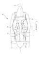
- FIG.1 illustrates a gas turbine engine 10 of a type preferably provided for use in subsonic flight, generally comprising in serial flow communication within a casing a fan 12 through which ambient air is propelled, a compressor section 14 for pressurizing the air, a combustion system 16 in which the compressed air is mixed with fuel and ignited for generating an annular stream of hot combustion gases, and a turbine section 18 for extracting energy from the combustion gases.
- the gas turbine engine 10 has a longitudinal central axis 11.
- the combustion system 16 includes a combustion chamber 20 defining a primary combustor 21 and a secondary combustor 22 and an electronic control unit (ECU) 23 controlling the actuation of the combustors 21, 22.
- ECU electronice control unit
- the combustion chamber 20 comprises a main lobe for the secondary combustor 22 and a smaller lobe for the primary combustor 21.
- the combustion chamber 20 may be unitary or made of several parts joined to each other.
- the secondary 22 and primary combustors 21 are annular and converge to each other in this example.
- the secondary combustor 22 in this example is arranged generally parallel to an axis of the engine, while the primary combustor 21 is disposed radially outward of the secondary combustor 22.
- the primary combustor 21 in this example is disposed on along a primary combustor axis A1 which intersects with a secondary combustor axis A2 parallel to the engine axis 11 at an acute angle ⁇ of 25°. It is contemplated that the angle ⁇ could be comprised between 20° and 30° in another example.
- the primary and secondary combustors 21, 22 are arranged in series. Although forming distinct combustion zones or chambers, the primary combustor 21 and the secondary combustor 22 are in fluid communication with each other. Exhaust gases from the primary combustor 21 reach the secondary combustor 22 before being evacuated via a single outlet 24 of the secondary combustor 22. A size of the primary combustor 21 may be determined to enable full combustion before the exhaust gases reach the secondary combustor 22.
- the combustion chamber 20 includes a plurality of air inlets.
- a primary series of air inlets 25 is disposed on the primary combustor 21 and a secondary series of air inlets 26 is disposed on the secondary combustor 22.
- the air inlets 25, 26 allow external air to feed the combustion. Additional air is carried through porous walls of the combustion chamber 20.
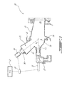
- An assembly of primary fuel injectors 28 is associated with the primary combustor 21, and a secondary fuel injector assembly 29, distinct from the primary fuel injector 28, is associated with the secondary combustor 22.
- the primary and secondary fuel injectors 28, 29 in use atomize fuel from a source delivered to them by associated primary and secondary fuel conduits 34, 35.
- the primary fuel injector 28 may be a series of discrete in-line or other suitable configuration fuel nozzles
- the secondary fuel injector assembly 29 may be an annular ring injector comprised of a much higher number of, typically smaller, fuel injection points such that effectively a continuous annular ring of fuel is injected into the secondary combustor, or other suitable configuration fuel nozzles.
- the primary fuel injector 28 includes 6 to 9 injectors and the secondary fuel injector 29 includes between 60 and 70 injectors. It is contemplated that the primary fuel injectors 28 may also be ring injector, or may employ another suitable configuration.
- the secondary fuel injector 29, in one example, may be substantially as described in co-pending applications 13/795,058 ( US 2014/0260260 A1 ), 13/795,082 ( US 2014/0260266 A1 ), 13/795,089 ( US 2014/0260297 A1 ) and 13/795,100 ( US 2014/0260298 A1 ), the entirety of each of which is hereby incorporated by reference.
- a manifold 30 is schematically shown as having a plurality of closely-spaced fuel injector sites 31 facing downstream on an annular support 32.
- the annular support 32 may be in the form of a full ring, or a segmented ring.
- the fuel injector sites 31 are circumferentially distributed in the annular support 32, and each accommodate a fuel nozzle (not shown).
- Flat spray nozzles may be used to reduce the number of fuel injector sites 31 yet have a similar spray coverage angle.
- the number of nozzle air inlets may be substantially greater than the number of fuel injector sites 31, and thus of fuel nozzles of the manifold 30.
- a continuous circumferential distribution of the nozzle air inlets relative to the discrete fuel nozzles may be used to create a relatively uniform air flow throughout the upstream zone in which the fuel stream is injected in order to have a relatively uniform flow of atomized fuel into the secondary combustor 22.
- the ECU 23 controls fuel delivered to the secondary and primary fuel injectors 28, 29.
- the ECU 23 is in communication with a fuel flow divider valve 33 which controls which of the primary and secondary fuel injectors 28, 29 will receive fuel.
- the ECU 23 controls the divider valve 33 based on one or more inputs.
- the input may be associated with a command from the pilot, or the electronic pilot assistant, such as speed, altitude, and acceleration.
- the one or more inputs received by the ECU 23 may be associated with engine regimes.
- Engine regimes correspond to flight conditions such as idle, taxiing or take-off and can be divided into at least two classes, namely lower power engine regimes and higher power engine regimes.
- Inputs may also include commands linked with turning on and off the combustion in the combustion chamber 20.
- An amount of fuel delivered to each of the fuel injectors 28, 29 may also be varied by the divider valve 33 upon control by the ECU 23. More or less power (and therefore fuel) is required from the combustion chamber 20 depending on the engine regime.
- This modulation of power is achieved by selectively actuating the secondary combustor 22 to assist the primary combustor 21 which has a limited combustion power.
- the primary combustor 21 is actuated alone for the lower power engine regimes, while the secondary combustor 22 is actuated only for the higher power engine regimes and is actuated in addition to the primary combustor 21.
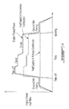
- FIG. 4 which shows a typical aircraft engine mission cycle
- one combustor such as the secondary combustor 22 in this example
- the secondary combustor 22 in this example may be optimized to provide an enhanced combustion efficiency at higher power, such as take-off or altitude cruising
- the other combustor the primary combustor 21 in this example
- FIG. 4 shows a typical aircraft engine mission cycle
- Combustion efficiency depends on several parameters such as one or more of given fuel flow, air flow, fuel pressure air flow, maximum temperature, number of fuel nozzles, or combustor volume. Other parameters are contemplated. Combustors and injectors that are operated in engine regimes they are not optimised for may produce environmentally hazardous by-products. For example, the secondary combustor 22 and injector 29 which may not be designed for enhanced combustion at lower power engine regimes may produce excess amounts of hydrocarbon when used in those regimes.
- the primary combustor 21 and injector 28 which may not be designed for enhanced combustion higher power engine regimes may produce nitric oxide when used in those regimes. While reducing consumption of fuel may reduce the production of nitric oxide and other environmentally hazardous gases, a flame of the injector 29 may become unstable. By having two distinct fuel injectors 28, 29, stability of the flame is also addressed since the primary fuel injector 28 may act as a back-up flame. Traditionally, it has been difficult to optimize for all flight phases with one combustion chamber.
- each of the combustors 21, 22 may be optimized.
- the combustion chamber 20 is operated by utilizing the primary combustor 21 only, and when higher power is needed, the combustion chamber 20 is operated such that the primary and secondary combustors 21, 22 are utilized.
- in high power mode at least 50% of the fuel delivered to the combustion chamber 20 is delivered to the secondary fuel injector 29 and less than 50% of the fuel delivered to the combustion chamber 20 is delivered to the primary fuel injector 28.
- the primary fuel injector 28 would be configured to deliver an appropriate fuel amount and scheduling to the primary combustor 21, while the secondary fuel injector 29 would be configured to deliver an appropriate fuel amount and scheduling to the secondary combustor 22.
- the primary fuel injector 28 delivers about 18 to 25% of the total fuel amount provided to the combustion chamber 20, while the secondary fuel injector 29 delivers a remainder (e.g. 75 to 82%) of the fuel to the combustion chamber 20.
- the primary combustor 21 delivers about 18 to 25% of the total thermal power, while the secondary combustor 22 provides the remainder.
- FIG. 5 a method 40 of actuating the combustion system 16 will be described.
- the method starts at step 42 with the actuation of only the primary combustor 21.
- Actuation may be based on a first input power request, and may correspond to a command from the cockpit or control system commanding a start to the combustion system 16 or to low power setting, such as ground idle or taxiing in the example described above. Because the input requires a fuel amount lower than a threshold between a lower and a higher power regimes (as discussed in the example above), step 42 is performed by the primary combustor 21 alone. The primary combustor 21 would be actuated alone as long as a the power required by the input is lower than a defined threshold defined between the low and high power modes.
- the primary combustor 21 is thus actuated, for example by the ECU 23 instructing the divider valve 33 to direct fuel to the primary fuel injector assembly 28 only.
- Step 42 therefore corresponds to lower power engine regimes, where only the primary combustor 21 is actuated in this example.
- the primary combustor 21 is configured to provide an enhanced combustion at the lower power engine regimes, and as such may emit reduced hydrocarbons or other unwanted by-products compared to traditional (single regime) combustors.
- step 44 in response to a second input power request above a threshold between low and high power regimes, such as a command from the cockpit or control system turning commanding high power operation such as takeoff power, the primary combustor 21 and secondary combustor 22 are actuated.
- the threshold corresponds to a predetermined fuel amount above which the secondary combustor 22 is to be actuated. In one embodiment, the threshold corresponds to a required fuel amount is higher than the maximum fuel amount which can be delivered by the primary fuel injector assembly 28.
- the ECU 23 may position the divider valve 33 to direct fuel to the secondary fuel injector assembly 29 in addition to the primary fuel injector assembly 28.
- the amount of fuel delivered to the fuel injectors 28, 29 may be varied by the divider valve 33 controlled by the ECU 23, and may depend on an amount of power required. For example, as higher powers are required, a higher fuel amount may be delivered to the secondary combustor 22. According to the example described above, a majority of the overall fuel supplied to the combustor 20 at step 44 is provided to the secondary combustor 22, the secondary combustor 22 may be configured by design to be optimized for more efficient combustion the higher power engine regimes, which may result in reduced nitride oxides or other by-products produced compared to traditional (single regime) combustors
- the dual stage combustion chamber and method described herein allows selectively using different combustion chambers in cooperation to provide complementary power in a selected engine regime.
- the combustors may be optimized to operate more efficiently at the selected regimes for which they are configured to operate, and may thus provide an overall enhanced efficiency, and/or reducing unwanted by-products.
- having multiple combustion chambers operated in cooperation allows having two flames which may act as a back-up for each other in case one flames out. Because one (in this case, the secondary) combustor may be configured for higher power engine regimes, it may be configured as a lean combustor with a low air ratio.
- the primary combustion chamber can be any suitable configuration.
- an annular primary chamber is described above, primary combustion may instead occur in a plurality of can combustors each with its fuel nozzle and igniter and in communication with the secondary chamber otherwise as described.
- the combustion chamber could include more than two combustion stages if desired, and any suitable number of combustion stages may be provided.
- the threshold between low and high power may be determined in any suitable fashion, and the split between fuel supply to combustion stages may be any suitable. Any suitable method of controlling fuel flow to the nozzle systems may be employed. Still other modifications which fall within the scope of the present invention will be apparent to those skilled in the art, in light of a review of this disclosure, and such modifications are intended to fall within the appended claims.
Landscapes
- Engineering & Computer Science (AREA)
- Chemical & Material Sciences (AREA)
- Combustion & Propulsion (AREA)
- Mechanical Engineering (AREA)
- General Engineering & Computer Science (AREA)
Applications Claiming Priority (1)
| Application Number | Priority Date | Filing Date | Title |
|---|---|---|---|
| US14/193,575 US9683744B2 (en) | 2014-02-28 | 2014-02-28 | Combustion system for a gas turbine engine and method of operating same |
Publications (1)
| Publication Number | Publication Date |
|---|---|
| EP2913587A1 true EP2913587A1 (de) | 2015-09-02 |
Family
ID=52633086
Family Applications (1)
| Application Number | Title | Priority Date | Filing Date |
|---|---|---|---|
| EP15156518.1A Withdrawn EP2913587A1 (de) | 2014-02-28 | 2015-02-25 | Verbrennungssystem für einen gasturbinenmotor und betriebsverfahren dafür |
Country Status (3)
| Country | Link |
|---|---|
| US (1) | US9683744B2 (de) |
| EP (1) | EP2913587A1 (de) |
| CA (1) | CA2882243C (de) |
Families Citing this family (15)
| Publication number | Priority date | Publication date | Assignee | Title |
|---|---|---|---|---|
| US9366187B2 (en) | 2013-03-12 | 2016-06-14 | Pratt & Whitney Canada Corp. | Slinger combustor |
| US9228747B2 (en) | 2013-03-12 | 2016-01-05 | Pratt & Whitney Canada Corp. | Combustor for gas turbine engine |
| US9958161B2 (en) | 2013-03-12 | 2018-05-01 | Pratt & Whitney Canada Corp. | Combustor for gas turbine engine |
| US9541292B2 (en) | 2013-03-12 | 2017-01-10 | Pratt & Whitney Canada Corp. | Combustor for gas turbine engine |
| US9127843B2 (en) | 2013-03-12 | 2015-09-08 | Pratt & Whitney Canada Corp. | Combustor for gas turbine engine |
| US10337736B2 (en) * | 2015-07-24 | 2019-07-02 | Pratt & Whitney Canada Corp. | Gas turbine engine combustor and method of forming same |
| US11713723B2 (en) | 2019-05-15 | 2023-08-01 | Pratt & Whitney Canada Corp. | Method and system for operating an engine |
| US11174792B2 (en) | 2019-05-21 | 2021-11-16 | General Electric Company | System and method for high frequency acoustic dampers with baffles |
| US11156164B2 (en) | 2019-05-21 | 2021-10-26 | General Electric Company | System and method for high frequency accoustic dampers with caps |
| US11760500B2 (en) | 2019-11-11 | 2023-09-19 | Pratt & Whitney Canada Corp. | Systems and methods for filling a fuel manifold of a gas turbine engine |
| US11346281B2 (en) * | 2020-08-21 | 2022-05-31 | Woodward, Inc. | Dual schedule flow divider valve, system, and method for use therein |
| GB202307700D0 (en) | 2023-05-23 | 2023-07-05 | Rolls Royce Plc | An improved combustor apparatus |
| GB202307701D0 (en) | 2023-05-23 | 2023-07-05 | Rolls Royce Plc | An improved combustor apparatus |
| GB202307703D0 (en) * | 2023-05-23 | 2023-07-05 | Rolls Royce Plc | An improved combustor apparatus |
| GB202307704D0 (en) * | 2023-05-23 | 2023-07-05 | Rolls Royce Plc | An improved combustor apparatus |
Citations (8)
| Publication number | Priority date | Publication date | Assignee | Title |
|---|---|---|---|---|
| US5687571A (en) * | 1995-02-20 | 1997-11-18 | Asea Brown Boveri Ag | Combustion chamber with two-stage combustion |
| US5829967A (en) * | 1995-03-24 | 1998-11-03 | Asea Brown Boveri Ag | Combustion chamber with two-stage combustion |
| US20110219779A1 (en) * | 2010-03-11 | 2011-09-15 | Honeywell International Inc. | Low emission combustion systems and methods for gas turbine engines |
| US20130327054A1 (en) * | 2011-03-25 | 2013-12-12 | Pratt & Whitney Canada Corp. | Hybrid slinger combustion system |
| US20140260298A1 (en) | 2013-03-12 | 2014-09-18 | Pratt & Whitney Canada Corp. | Combustor for gas turbine engine |
| US20140260260A1 (en) | 2013-03-12 | 2014-09-18 | Pratt & Whitney Canada Corp. | Combustor for gas turbine engine |
| US20140260266A1 (en) | 2013-03-12 | 2014-09-18 | Pratt & Whitney Canada Corp. | Combustor for gas turbine engine |
| US20140260297A1 (en) | 2013-03-12 | 2014-09-18 | Pratt & Whitney Canada Corp. | Combustor for gas turbine engine |
Family Cites Families (7)
| Publication number | Priority date | Publication date | Assignee | Title |
|---|---|---|---|---|
| US5339635A (en) | 1987-09-04 | 1994-08-23 | Hitachi, Ltd. | Gas turbine combustor of the completely premixed combustion type |
| NO179883C (no) | 1994-10-14 | 1997-01-08 | Ulstein Turbine As | Drivstoff-/luftblandingsanordning |
| US5983642A (en) | 1997-10-13 | 1999-11-16 | Siemens Westinghouse Power Corporation | Combustor with two stage primary fuel tube with concentric members and flow regulating |
| US6928823B2 (en) | 2001-08-29 | 2005-08-16 | Hitachi, Ltd. | Gas turbine combustor and operating method thereof |
| JP4134311B2 (ja) | 2002-03-08 | 2008-08-20 | 独立行政法人 宇宙航空研究開発機構 | ガスタービン燃焼器 |
| US8387398B2 (en) * | 2007-09-14 | 2013-03-05 | Siemens Energy, Inc. | Apparatus and method for controlling the secondary injection of fuel |
| US9068748B2 (en) * | 2011-01-24 | 2015-06-30 | United Technologies Corporation | Axial stage combustor for gas turbine engines |
-
2014
- 2014-02-28 US US14/193,575 patent/US9683744B2/en active Active
-
2015
- 2015-02-17 CA CA2882243A patent/CA2882243C/en active Active
- 2015-02-25 EP EP15156518.1A patent/EP2913587A1/de not_active Withdrawn
Patent Citations (8)
| Publication number | Priority date | Publication date | Assignee | Title |
|---|---|---|---|---|
| US5687571A (en) * | 1995-02-20 | 1997-11-18 | Asea Brown Boveri Ag | Combustion chamber with two-stage combustion |
| US5829967A (en) * | 1995-03-24 | 1998-11-03 | Asea Brown Boveri Ag | Combustion chamber with two-stage combustion |
| US20110219779A1 (en) * | 2010-03-11 | 2011-09-15 | Honeywell International Inc. | Low emission combustion systems and methods for gas turbine engines |
| US20130327054A1 (en) * | 2011-03-25 | 2013-12-12 | Pratt & Whitney Canada Corp. | Hybrid slinger combustion system |
| US20140260298A1 (en) | 2013-03-12 | 2014-09-18 | Pratt & Whitney Canada Corp. | Combustor for gas turbine engine |
| US20140260260A1 (en) | 2013-03-12 | 2014-09-18 | Pratt & Whitney Canada Corp. | Combustor for gas turbine engine |
| US20140260266A1 (en) | 2013-03-12 | 2014-09-18 | Pratt & Whitney Canada Corp. | Combustor for gas turbine engine |
| US20140260297A1 (en) | 2013-03-12 | 2014-09-18 | Pratt & Whitney Canada Corp. | Combustor for gas turbine engine |
Also Published As
| Publication number | Publication date |
|---|---|
| US9683744B2 (en) | 2017-06-20 |
| CA2882243A1 (en) | 2015-08-28 |
| CA2882243C (en) | 2023-01-03 |
| US20150247641A1 (en) | 2015-09-03 |
Similar Documents
| Publication | Publication Date | Title |
|---|---|---|
| CA2882243C (en) | Combustion system for a gas turbine engine and method of operating same | |
| US8677731B2 (en) | Hybrid slinger combustion system | |
| EP3473842B1 (de) | Elektrisches reiseflugpumpensystem | |
| EP3183448B1 (de) | Funkenzünder | |
| US10012387B2 (en) | Fuel supply system for a gas turbine engine | |
| US9458768B2 (en) | Algae-derived fuel/water emulsion | |
| US11988156B2 (en) | Engine assembly and method of operation | |
| CN111788431A (zh) | 燃烧器组件燃料控制 | |
| US10436117B2 (en) | Carbureted fuel injection system for a gas turbine engine | |
| WO2019098880A1 (ru) | Многоколлекторное устройство подачи топлива в камеру сгорания газотурбинного двигателя | |
| EP0705384B1 (de) | Kraftstoff-druckverlauf beim start einer gasturbine | |
| US20240133352A1 (en) | Duplex Turbine Guide Vane Assembly | |
| WO2016039993A1 (en) | Liquid propellant rocket engine with afterburner combustor | |
| US12111056B2 (en) | Combustor with central fuel injection and downstream air mixing | |
| EP4411225B1 (de) | Brennkammer mit luft-kraftstoff-mischer zur erzeugung einer gemischten cloud | |
| EP3367000B1 (de) | Kraftstoffausgabesystem und -verfahren für eine brennkammer | |
| RU174498U1 (ru) | Силовая установка гиперзвукового летательного аппарата |
Legal Events
| Date | Code | Title | Description |
|---|---|---|---|
| PUAI | Public reference made under article 153(3) epc to a published international application that has entered the european phase |
Free format text: ORIGINAL CODE: 0009012 |
|
| AK | Designated contracting states |
Kind code of ref document: A1 Designated state(s): AL AT BE BG CH CY CZ DE DK EE ES FI FR GB GR HR HU IE IS IT LI LT LU LV MC MK MT NL NO PL PT RO RS SE SI SK SM TR |
|
| AX | Request for extension of the european patent |
Extension state: BA ME |
|
| 17P | Request for examination filed |
Effective date: 20160302 |
|
| RBV | Designated contracting states (corrected) |
Designated state(s): AL AT BE BG CH CY CZ DE DK EE ES FI FR GB GR HR HU IE IS IT LI LT LU LV MC MK MT NL NO PL PT RO RS SE SI SK SM TR |
|
| STAA | Information on the status of an ep patent application or granted ep patent |
Free format text: STATUS: EXAMINATION IS IN PROGRESS |
|
| 17Q | First examination report despatched |
Effective date: 20190528 |
|
| STAA | Information on the status of an ep patent application or granted ep patent |
Free format text: STATUS: THE APPLICATION IS DEEMED TO BE WITHDRAWN |
|
| 18D | Application deemed to be withdrawn |
Effective date: 20121210 |
|
| R18D | Application deemed to be withdrawn (corrected) |
Effective date: 20191210 |