EP2913483A1 - Method for removing a rotor bucket from a turbomachine rotor wheel - Google Patents
Method for removing a rotor bucket from a turbomachine rotor wheel Download PDFInfo
- Publication number
- EP2913483A1 EP2913483A1 EP15156150.3A EP15156150A EP2913483A1 EP 2913483 A1 EP2913483 A1 EP 2913483A1 EP 15156150 A EP15156150 A EP 15156150A EP 2913483 A1 EP2913483 A1 EP 2913483A1
- Authority
- EP
- European Patent Office
- Prior art keywords
- base portion
- bucket
- rotor wheel
- pulling device
- ram
- Prior art date
- Legal status (The legal status is an assumption and is not a legal conclusion. Google has not performed a legal analysis and makes no representation as to the accuracy of the status listed.)
- Granted
Links
Images





Classifications
-
- F—MECHANICAL ENGINEERING; LIGHTING; HEATING; WEAPONS; BLASTING
- F01—MACHINES OR ENGINES IN GENERAL; ENGINE PLANTS IN GENERAL; STEAM ENGINES
- F01D—NON-POSITIVE DISPLACEMENT MACHINES OR ENGINES, e.g. STEAM TURBINES
- F01D5/00—Blades; Blade-carrying members; Heating, heat-insulating, cooling or antivibration means on the blades or the members
- F01D5/005—Repairing methods or devices
-
- F—MECHANICAL ENGINEERING; LIGHTING; HEATING; WEAPONS; BLASTING
- F01—MACHINES OR ENGINES IN GENERAL; ENGINE PLANTS IN GENERAL; STEAM ENGINES
- F01D—NON-POSITIVE DISPLACEMENT MACHINES OR ENGINES, e.g. STEAM TURBINES
- F01D25/00—Component parts, details, or accessories, not provided for in, or of interest apart from, other groups
- F01D25/28—Supporting or mounting arrangements, e.g. for turbine casing
- F01D25/285—Temporary support structures, e.g. for testing, assembling, installing, repairing; Assembly methods using such structures
-
- F—MECHANICAL ENGINEERING; LIGHTING; HEATING; WEAPONS; BLASTING
- F01—MACHINES OR ENGINES IN GENERAL; ENGINE PLANTS IN GENERAL; STEAM ENGINES
- F01D—NON-POSITIVE DISPLACEMENT MACHINES OR ENGINES, e.g. STEAM TURBINES
- F01D5/00—Blades; Blade-carrying members; Heating, heat-insulating, cooling or antivibration means on the blades or the members
- F01D5/30—Fixing blades to rotors; Blade roots ; Blade spacers
- F01D5/3023—Fixing blades to rotors; Blade roots ; Blade spacers of radial insertion type, e.g. in individual recesses
- F01D5/303—Fixing blades to rotors; Blade roots ; Blade spacers of radial insertion type, e.g. in individual recesses in a circumferential slot
- F01D5/3038—Fixing blades to rotors; Blade roots ; Blade spacers of radial insertion type, e.g. in individual recesses in a circumferential slot the slot having inwardly directed abutment faces on both sides
-
- F—MECHANICAL ENGINEERING; LIGHTING; HEATING; WEAPONS; BLASTING
- F01—MACHINES OR ENGINES IN GENERAL; ENGINE PLANTS IN GENERAL; STEAM ENGINES
- F01D—NON-POSITIVE DISPLACEMENT MACHINES OR ENGINES, e.g. STEAM TURBINES
- F01D5/00—Blades; Blade-carrying members; Heating, heat-insulating, cooling or antivibration means on the blades or the members
- F01D5/30—Fixing blades to rotors; Blade roots ; Blade spacers
- F01D5/32—Locking, e.g. by final locking blades or keys
-
- F—MECHANICAL ENGINEERING; LIGHTING; HEATING; WEAPONS; BLASTING
- F05—INDEXING SCHEMES RELATING TO ENGINES OR PUMPS IN VARIOUS SUBCLASSES OF CLASSES F01-F04
- F05D—INDEXING SCHEME FOR ASPECTS RELATING TO NON-POSITIVE-DISPLACEMENT MACHINES OR ENGINES, GAS-TURBINES OR JET-PROPULSION PLANTS
- F05D2230/00—Manufacture
- F05D2230/60—Assembly methods
- F05D2230/68—Assembly methods using auxiliary equipment for lifting or holding
-
- Y—GENERAL TAGGING OF NEW TECHNOLOGICAL DEVELOPMENTS; GENERAL TAGGING OF CROSS-SECTIONAL TECHNOLOGIES SPANNING OVER SEVERAL SECTIONS OF THE IPC; TECHNICAL SUBJECTS COVERED BY FORMER USPC CROSS-REFERENCE ART COLLECTIONS [XRACs] AND DIGESTS
- Y10—TECHNICAL SUBJECTS COVERED BY FORMER USPC
- Y10T—TECHNICAL SUBJECTS COVERED BY FORMER US CLASSIFICATION
- Y10T29/00—Metal working
- Y10T29/49—Method of mechanical manufacture
- Y10T29/49316—Impeller making
- Y10T29/49318—Repairing or disassembling
Definitions
- the subject matter disclosed herein relates to the art of turbomachines and, more particularly, to a method of removing a rotor bucket from a turbomachine rotor wheel.
- Steam turbines typically include rotating buckets or blades and stationary nozzles. Steam is passed through a number of turbine stages. Each stage includes a row of stationary nozzles and rotating blades mounted to a rotor wheel. Steam expands through the number of turbine stages to rotate rotor wheel creating work.
- the buckets are typically mounted to the rotor wheel through a dovetail attachment.
- the rotor wheel may include an internal, circumferential dovetail.
- Each bucket or blade has a corresponding dovetail that cooperates with the internal, circumferential dovetail.
- each rotor wheel features a loading position or gate opening configured to receive each bucket.
- Each bucket is mounted to the rotor wheel and manipulated into place about the outer diametric surface. Once all buckets are mounted, a closure bucket is installed in the loading portion and secured to the rotor wheel to prevent bucket liberation.
- a method of removing a bucket from a turbomachine rotor wheel includes exposing a base portion of the bucket, positioning a pulling device radially outward of the base portion, connecting the base portion of the bucket to the pulling device through a linking rod, exerting a radially outwardly directed force on the linking rod through the pulling device, and removing the base portion from the rotor wheel.
- a method of removing a bucket from a rotor wheel includes positioning a ram radially outward of the base portion, connecting the base portion of the bucket to a ram, exerting a radially outwardly directed force on the base portion, and removing the base portion from the rotor wheel.
- a turbomachine is illustrated generally at 2 in FIG. 1 .
- Turbomachine 2 is shown in the form of a steam turbine 4 having a turbine housing 16 that encloses a number of turbine stages three of which are indicated at 20, 21 and 22.
- Each turbine stage 20-22 includes a corresponding plurality of stationary airfoil members or nozzles, such as indicated at 24 in connection with stage 22, arranged upstream from a plurality of rotating airfoil members or buckets, such as shown at 26.
- Rotating airfoil members 26 are mounted to a rotor wheel 30 within steam turbine 4.
- steam from a boiler or similar arrangement is directed into steam turbine 4.
- the steam expands through stages 20-22 creating work that is used to power an external component 34.
- External component 34 may take on a variety of forms including a generator or a pump or other mechanically driven systems. That is, steam turbine 4 could also be used as a power source for a vehicle.
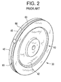
- rotor wheel 30 includes a rotor wheel body 40 having a first face 42 and an opposing, second face 43 that are joined by an outer diametric surface 45.
- a bucket receiving slot 60 is formed in outer diametric surface 45.
- Bucket receiving slot 60 supports plurality of rotating airfoil members 26 about outer diametric surface 45.
- Bucket receiving slot 60 includes a bucket mounting opening 63 and interior cavity 66 formed in rotor wheel body 40.
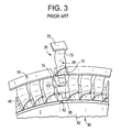
- Each of the plurality of rotating airfoil members 26 includes a base portion 72 ( FIG. 3 ) that supports an airfoil portion 73 and a mounting member or dovetail 74.
- Airfoil portion 73 includes a ring element 75 that forms part of a circumferentially extending rotor ring 76.
- Dovetail 74 is shaped to nest within bucket receiving slot 60.
- Each of the plurality of rotating airfoil members 26 is guided into bucket receiving slot 60 and manipulated into position.
- a closure bucket 80 is installed into bucket receiving slot 60 and held in place by mechanical fasteners or grub screws 82 and 84, such as shown in FIG. 4
- steam turbine 4 may be taken offline for maintenance and/or repair.
- Maintenance includes an inspection of the buckets.
- a bucket(s) may become damaged.
- the damaged bucket(s) is removed and replaced.
- Removing the damaged bucket first requires removal of the closure bucket 80 which may, itself, be damaged.
- removal of a damaged closure bucket 80 includes removing grub screws 82 and 84 and airfoil portion 73, as shown in FIG. 5 , to expose an upper surface 90 of base portion 72.
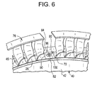
- a bore 96 is formed in closure bucket 80, as shown in FIG. 6 . Bore 96 extends radially inwardly into base portion 72.
- a plurality of threads 100 are formed in base portion 72 along bore 96.
- a pulling device 110 is arranged radially outward of closure bucket 80, as shown in FIG. 7 .
- Pulling device 110 includes a base 112 supported by rotor ring 76 and a ram 114. Pulling device 110 may rely upon air pressure, hydraulic pressure, or electrical current to operate ram 114.
- Ram 114 is connected to base portion 72 through a linking rod 120.
- Linking rod 120 includes a plurality of threads (not separately labeled) that engage with threads 100 in base portion 72.
- Ram 114 is actuated to exert a radially outwardly directed force on base portion 72 through linking rod 120. The radially outwardly directed force may cause base portion 72 to release from rotor wheel 30, as shown in FIG. 8 .
- the remaining buckets may be circumferentially shifted to bucket mounting opening 63 and removed from rotor wheel 30 for inspection and/or replacement.
- base portion and pin may be broken up into a plurality of pieces, indicated generally at 140, and removed, as shown in FIG. 9 .
- the remaining buckets may be circumferentially shifted to bucket mounting opening 63 and removed. If the additional buckets resist removal efforts, all airfoil portions may be removed and corresponding base portions broken up into pieces 140 to enable removal.
- the method may also be employed to remove buckets from rotor wheels arranged in other turbomachine systems including compressors and gas turbines. Further, it should be understood that the method may be used to remove the closure bucket without requiring that the rotor wheel be separated from other rotor wheels or removed from the turbine rotor. The destruction of a single bucket, in situ, reduces downtime and overall maintenance costs associated with the steam turbine 4.
Landscapes
- Engineering & Computer Science (AREA)
- Mechanical Engineering (AREA)
- General Engineering & Computer Science (AREA)
- Turbine Rotor Nozzle Sealing (AREA)
Abstract
Description
- The subject matter disclosed herein relates to the art of turbomachines and, more particularly, to a method of removing a rotor bucket from a turbomachine rotor wheel.
- Steam turbines typically include rotating buckets or blades and stationary nozzles. Steam is passed through a number of turbine stages. Each stage includes a row of stationary nozzles and rotating blades mounted to a rotor wheel. Steam expands through the number of turbine stages to rotate rotor wheel creating work.
- The buckets are typically mounted to the rotor wheel through a dovetail attachment. The rotor wheel may include an internal, circumferential dovetail. Each bucket or blade has a corresponding dovetail that cooperates with the internal, circumferential dovetail. Generally, each rotor wheel features a loading position or gate opening configured to receive each bucket. Each bucket is mounted to the rotor wheel and manipulated into place about the outer diametric surface. Once all buckets are mounted, a closure bucket is installed in the loading portion and secured to the rotor wheel to prevent bucket liberation.
- According to one aspect of an exemplary embodiment, a method of removing a bucket from a turbomachine rotor wheel includes exposing a base portion of the bucket, positioning a pulling device radially outward of the base portion, connecting the base portion of the bucket to the pulling device through a linking rod, exerting a radially outwardly directed force on the linking rod through the pulling device, and removing the base portion from the rotor wheel.
- According to another aspect of an exemplary embodiment, a method of removing a bucket from a rotor wheel includes positioning a ram radially outward of the base portion, connecting the base portion of the bucket to a ram, exerting a radially outwardly directed force on the base portion, and removing the base portion from the rotor wheel.
- These and other advantages and features will become more apparent from the following description taken in conjunction with the drawings.
- The subject matter, which is regarded as the invention, is particularly pointed out and distinctly claimed in the claims at the conclusion of the specification. The foregoing and other features, and advantages of the invention are apparent from the following detailed description taken in conjunction with the accompanying drawings in which:
-
FIG. 1 is schematic view of a turbomachine shown in the form of a steam turbine in accordance with the prior art -
FIG. 2 is a perspective view of a rotor wheel of the turbomachine ofFIG. 1 ; -
FIG. 3 is a perspective view of a closure bucket spaced from the rotor wheel ofFIG. 2 ; -
FIG. 4 is a perspective view of the closure bucket ofFIG. 3 installed in the rotor wheel; -
FIG. 5 is a perspective view of a bucket portion of the closure bucket removed, in accordance with an exemplary embodiment; -
FIG. 6 is a perspective view of a threaded opening formed in a base portion of the closure bucket ofFIG. 5 , in accordance with an exemplary embodiment; -
FIG. 7 is a perspective view of a pulling device coupled to the base portion of the closure bucket ofFIG. 6 , in accordance with an exemplary embodiment; -
FIG. 8 is a perspective view of the base portion of the closure bucket being removed from the rotor wheel by the pulling device, in accordance with an aspect of an exemplary embodiment; and -
FIG. 9 is a perspective view of the base portion of the closure bucket being removed in pieces, in accordance with another aspect of an exemplary embodiment. - The detailed description explains embodiments of the invention, together with advantages and features, by way of example with reference to the drawings.
- A turbomachine is illustrated generally at 2 in
FIG. 1 .Turbomachine 2 is shown in the form of asteam turbine 4 having aturbine housing 16 that encloses a number of turbine stages three of which are indicated at 20, 21 and 22. Of course, it would be appreciated by one of ordinary skill in the art that the number of turbine stages could vary. Each turbine stage 20-22 includes a corresponding plurality of stationary airfoil members or nozzles, such as indicated at 24 in connection withstage 22, arranged upstream from a plurality of rotating airfoil members or buckets, such as shown at 26. Rotatingairfoil members 26 are mounted to arotor wheel 30 withinsteam turbine 4. - With this arrangement, steam from a boiler or similar arrangement (not shown) is directed into
steam turbine 4. The steam expands through stages 20-22 creating work that is used to power anexternal component 34.External component 34 may take on a variety of forms including a generator or a pump or other mechanically driven systems. That is,steam turbine 4 could also be used as a power source for a vehicle. - In accordance with the exemplary embodiment illustrated in
FIG. 2 ,rotor wheel 30 includes arotor wheel body 40 having afirst face 42 and an opposing,second face 43 that are joined by an outerdiametric surface 45. Abucket receiving slot 60 is formed in outerdiametric surface 45.Bucket receiving slot 60 supports plurality of rotatingairfoil members 26 about outerdiametric surface 45.Bucket receiving slot 60 includes a bucket mounting opening 63 andinterior cavity 66 formed inrotor wheel body 40. Each of the plurality of rotatingairfoil members 26 includes a base portion 72 (FIG. 3 ) that supports anairfoil portion 73 and a mounting member ordovetail 74.Airfoil portion 73 includes aring element 75 that forms part of a circumferentially extendingrotor ring 76.Dovetail 74 is shaped to nest withinbucket receiving slot 60. Each of the plurality of rotatingairfoil members 26 is guided intobucket receiving slot 60 and manipulated into position. Once all buckets are installed, aclosure bucket 80 is installed intobucket receiving slot 60 and held in place by mechanical fasteners orgrub screws FIG. 4 - Over the course of time,
steam turbine 4 may be taken offline for maintenance and/or repair. Maintenance includes an inspection of the buckets. During operation a bucket(s) may become damaged. The damaged bucket(s) is removed and replaced. Removing the damaged bucket first requires removal of theclosure bucket 80 which may, itself, be damaged. In accordance with an aspect of an exemplary embodiment, removal of a damagedclosure bucket 80 includes removinggrub screws airfoil portion 73, as shown inFIG. 5 , to expose anupper surface 90 ofbase portion 72. After removingairfoil portion 73, abore 96 is formed inclosure bucket 80, as shown inFIG. 6 . Bore 96 extends radially inwardly intobase portion 72. A plurality ofthreads 100 are formed inbase portion 72 alongbore 96. - After forming
threads 100, apulling device 110 is arranged radially outward ofclosure bucket 80, as shown inFIG. 7 .Pulling device 110 includes abase 112 supported byrotor ring 76 and aram 114.Pulling device 110 may rely upon air pressure, hydraulic pressure, or electrical current to operateram 114. Ram 114 is connected tobase portion 72 through a linkingrod 120. Linkingrod 120 includes a plurality of threads (not separately labeled) that engage withthreads 100 inbase portion 72. Ram 114 is actuated to exert a radially outwardly directed force onbase portion 72 through linkingrod 120. The radially outwardly directed force may causebase portion 72 to release fromrotor wheel 30, as shown inFIG. 8 . At this point, the remaining buckets may be circumferentially shifted to bucket mounting opening 63 and removed fromrotor wheel 30 for inspection and/or replacement. - At this point it should be understood that the exemplary embodiments describe a method for removing a closure bucket from a rotor wheel. In the event that the closure bucket may does not release from rotor wheel, base portion and pin may be broken up into a plurality of pieces, indicated generally at 140, and removed, as shown in
FIG. 9 . At this point, the remaining buckets may be circumferentially shifted tobucket mounting opening 63 and removed. If the additional buckets resist removal efforts, all airfoil portions may be removed and corresponding base portions broken up intopieces 140 to enable removal. It should also be understood that while described in terms of removing a bucket from a rotor wheel in a steam turbine, the method may also be employed to remove buckets from rotor wheels arranged in other turbomachine systems including compressors and gas turbines. Further, it should be understood that the method may be used to remove the closure bucket without requiring that the rotor wheel be separated from other rotor wheels or removed from the turbine rotor. The destruction of a single bucket, in situ, reduces downtime and overall maintenance costs associated with thesteam turbine 4. - While the invention has been described in detail in connection with only a limited number of embodiments, it should be readily understood that the invention is not limited to such disclosed embodiments. Rather, the invention can be modified to incorporate any number of variations, alterations, substitutions or equivalent arrangements not heretofore described, but which are commensurate with the spirit and scope of the invention. Additionally, while various embodiments of the invention have been described, it is to be understood that aspects of the invention may include only some of the described embodiments. Accordingly, the invention is not to be seen as limited by the foregoing description, but is only limited by the scope of the appended claims.
Claims (15)
- A method of removing a bucket (80) from a turbomachine (2) rotor wheel (30), the method comprising:exposing a base portion (72) of the bucket (80);positioning a pulling device (110) radially outwardly of the base portion (72);connecting the base portion (72) of the bucket (80) to the pulling device (110) through a linking rod (120);exerting an axially outwardly directed force on the linking rod (120) through the pulling device (110); andremoving the base portion (72) from the turbomachine (2) rotor wheel (30).
- The method of claim 1, wherein exposing the base portion (72) of the bucket (80) includes removing an airfoil portion (73) from the base portion (72).
- The method of claim 1 or 2, wherein connecting the base portion (72) of the bucket (80) includes forming a bore (96) into the base portion (72).
- The method of claim 3, further comprising: forming a plurality of threads (100) along the bore (96).
- The method of any of claims 1 to 4, wherein positioning the pulling device (110) includes supporting the pulling device (110) on a rotor ring (76) surrounding the turbomachine (2) rotor wheel (30).
- The method of any preceding claim, wherein positioning the pulling device (110) includes supporting a ram (114) radially outwardly of the base portion (72).
- The method of any preceding claim, wherein exerting the axially outwardly directed force includes directing a hydraulic fluid into the pulling device (110).
- The method of any preceding claim, wherein exerting the axially outwardly directed force includes operating a screw (82) in the pulling device (110).
- The method of any preceding claim, wherein removing the base portion (72) further comprises:breaking the base portion (72) into multiple pieces (140); andremoving each of the multiple pieces (140) from the turbomachine (2) rotor wheel (30).
- A method of removing a bucket (80) from a rotor wheel (30) comprising:positioning a ram (114) radially outwardly of the bucket (80);connecting a base portion (72) of the bucket (80) to a ram (114);exerting an axially outwardly directed force on the base portion (72); andremoving the base portion (72) from the rotor wheel (30).
- The method of claim 10, wherein connecting the base portion (72) of the bucket (80 includes forming a bore (96) into the base portion (72).
- The method of claim 11, further comprising: forming a plurality of threads (100) along the bore (96).
- The method of claim 12, wherein connecting the base portion (72) to the ram (114) includes establishing a threaded connection between the ram (114) and the plurality of threads (100).
- The method of any of any of claims 10 to 13, wherein positioning the ram (114) includes supporting the ram (114) on a rotor ring (76) surrounding the rotor wheel (30).
- The method of any of claims 10 to 14, wherein exerting the axially outwardly directed force includes forcing a linking rod (120) radially outwardly of the rotor wheel (30) into the ram (114).
Applications Claiming Priority (1)
| Application Number | Priority Date | Filing Date | Title |
|---|---|---|---|
| US14/190,759 US9382801B2 (en) | 2014-02-26 | 2014-02-26 | Method for removing a rotor bucket from a turbomachine rotor wheel |
Publications (2)
| Publication Number | Publication Date |
|---|---|
| EP2913483A1 true EP2913483A1 (en) | 2015-09-02 |
| EP2913483B1 EP2913483B1 (en) | 2017-07-05 |
Family
ID=52779455
Family Applications (1)
| Application Number | Title | Priority Date | Filing Date |
|---|---|---|---|
| EP15156150.3A Not-in-force EP2913483B1 (en) | 2014-02-26 | 2015-02-23 | Method for removing a rotor bucket from a turbomachine rotor wheel |
Country Status (3)
| Country | Link |
|---|---|
| US (1) | US9382801B2 (en) |
| EP (1) | EP2913483B1 (en) |
| JP (1) | JP2015161305A (en) |
Families Citing this family (1)
| Publication number | Priority date | Publication date | Assignee | Title |
|---|---|---|---|---|
| US9381602B2 (en) * | 2014-05-14 | 2016-07-05 | General Electric Company | Turbomachine bucket displacement apparatus and method of use |
Citations (3)
| Publication number | Priority date | Publication date | Assignee | Title |
|---|---|---|---|---|
| US3042368A (en) * | 1960-06-29 | 1962-07-03 | Worthington Corp | Removable lock for blade wheel assembly |
| US4820127A (en) * | 1988-01-29 | 1989-04-11 | Westinghouse Electric Corp. | Blade support and blade assembly |
| US20030049130A1 (en) * | 2001-09-13 | 2003-03-13 | Miller Harold Edward | Method and system for replacing a compressor blade |
Family Cites Families (131)
| Publication number | Priority date | Publication date | Assignee | Title |
|---|---|---|---|---|
| US721241A (en) | 1900-09-11 | 1903-02-24 | Russell Car And Snow Plow Company | Snow-plow. |
| US768597A (en) | 1902-08-21 | 1904-08-30 | Gen Electric | Turbine-bucket. |
| US1048158A (en) | 1910-05-14 | 1912-12-24 | Gerardus Post Herrick | Rotary engine. |
| US1619133A (en) | 1922-01-07 | 1927-03-01 | Westinghouse Electric & Mfg Co | Blade fastening |
| US1502904A (en) | 1923-06-22 | 1924-07-29 | Gen Electric | Elastic-fluid turbine rotor and method of avoiding tangential bucket vibration therein |
| US1659516A (en) | 1926-06-10 | 1928-02-14 | American Dairy Supply Company | Bottle-cap machine |
| US2032812A (en) | 1932-03-12 | 1936-03-03 | Quattrin Sante | Apparatus for making confections |
| US2047501A (en) | 1934-05-03 | 1936-07-14 | Spontan Ab | Steam or gas turbine |
| US2330967A (en) | 1939-12-02 | 1943-10-05 | Nestle S Milk Products Inc | Machine for processing food products |
| US2593714A (en) | 1943-06-30 | 1952-04-22 | Roy H Robinson | Method of making cellular structures |
| BE480934A (en) | 1945-06-02 | |||
| US2790620A (en) | 1952-07-09 | 1957-04-30 | Gen Electric | Multiple finger dovetail attachment for turbine bucket |
| US3199836A (en) | 1964-05-04 | 1965-08-10 | Gen Electric | Axial flow turbo-machine blade with abrasive tip |
| US3624830A (en) | 1969-11-28 | 1971-11-30 | Hi Life Packing Co | Food-processing apparatus |
| US3673668A (en) | 1970-08-31 | 1972-07-04 | Ind Solvers Inc | Vane ejector tool |
| US3794803A (en) | 1971-04-21 | 1974-02-26 | J Valdeck | Apparatus and method for making needle tubing |
| US4096614A (en) | 1975-09-02 | 1978-06-27 | General Electric Company | Method and apparatus for removing stator vanes |
| US4088421A (en) | 1976-09-30 | 1978-05-09 | General Electric Company | Coverplate damping arrangement |
| US4078290A (en) | 1976-11-08 | 1978-03-14 | Nasa | Stator rotor tools |
| US4118136A (en) | 1977-06-03 | 1978-10-03 | General Electric Company | Apparatus for attaching tubing to a rotating disk |
| US4136516A (en) | 1977-06-03 | 1979-01-30 | General Electric Company | Gas turbine with secondary cooling means |
| US4190398A (en) | 1977-06-03 | 1980-02-26 | General Electric Company | Gas turbine engine and means for cooling same |
| US4142831A (en) | 1977-06-15 | 1979-03-06 | General Electric Company | Liquid-cooled turbine bucket with enhanced heat transfer performance |
| US4185369A (en) | 1978-03-22 | 1980-01-29 | General Electric Company | Method of manufacture of cooled turbine or compressor buckets |
| US4244676A (en) | 1979-06-01 | 1981-01-13 | General Electric Company | Cooling system for a gas turbine using a cylindrical insert having V-shaped notch weirs |
| US4392613A (en) | 1980-12-22 | 1983-07-12 | Armco Inc. | Discharge gap cleaning device |
| US4400137A (en) * | 1980-12-29 | 1983-08-23 | Elliott Turbomachinery Co., Inc. | Rotor assembly and methods for securing a rotor blade therewithin and removing a rotor blade therefrom |
| ES8704029A1 (en) | 1984-06-06 | 1987-03-01 | Westinghouse Electric Corp | Replacement of split pins in guide tubes. |
| US4720898A (en) | 1984-06-06 | 1988-01-26 | Westinghouse Electric Corp. | Replacement of split pins in guide tubes |
| US4783204A (en) | 1986-08-05 | 1988-11-08 | Westinghouse Electric Corp. | Apparatus and method for drying steam |
| FR2630951B1 (en) * | 1988-05-03 | 1991-02-15 | Alsthom | PROCESS AND DEVICE FOR EXTRACTING PACKS OF STEAM TURBINE FINS |
| GB8914156D0 (en) | 1989-06-20 | 1989-08-09 | Refurbished Turbine Components | Apparatus for use in the repair of machines |
| US5235745A (en) | 1989-06-20 | 1993-08-17 | Refurbished Turbine Components Limited | Method of repairing turbine blades on a rotor |
| EP0618779B1 (en) | 1991-12-20 | 2000-05-03 | FISHER & PAYKEL LIMITED | Dishwasher |
| US5249918A (en) | 1991-12-31 | 1993-10-05 | General Electric Company | Apparatus and methods for minimizing or eliminating solid particle erosion in double-flow steam turbines |
| WO1994026176A1 (en) | 1993-05-15 | 1994-11-24 | Ueth & Haug Gmbh | Endoprosthesis cutting-off device |
| US5425622A (en) | 1993-12-23 | 1995-06-20 | United Technologies Corporation | Turbine blade attachment means |
| US5593273A (en) | 1994-03-28 | 1997-01-14 | General Electric Co. | Double flow turbine with axial adjustment and replaceable steam paths and methods of assembly |
| JPH07286503A (en) | 1994-04-20 | 1995-10-31 | Hitachi Ltd | High efficiency gas turbine |
| US5605487A (en) | 1994-05-13 | 1997-02-25 | Memc Electric Materials, Inc. | Semiconductor wafer polishing appartus and method |
| GB2293628B (en) | 1994-09-27 | 1998-04-01 | Europ Gas Turbines Ltd | Turbines |
| US6125819A (en) | 1995-08-08 | 2000-10-03 | Strieber; Louis Charles | Rotating piston engine with variable effective compression stroke |
| US5850810A (en) | 1995-08-08 | 1998-12-22 | Strieber; Louis Charles | Rotating piston engine with variable effective compression stroke |
| US5622142A (en) | 1995-08-08 | 1997-04-22 | Strieber; Louis C. | Rotating piston engine with variable effective compression stroke |
| DE19654471B4 (en) | 1996-12-27 | 2006-05-24 | Alstom | Rotor of a turbomachine |
| US20050120715A1 (en) | 1997-12-23 | 2005-06-09 | Christion School Of Technology Charitable Foundation Trust | Heat energy recapture and recycle and its new applications |
| US20050049621A1 (en) | 1998-08-12 | 2005-03-03 | Vladimir Feingold | Intracorneal lens placement method and apparatus |
| WO2006007545A2 (en) | 1998-08-12 | 2006-01-19 | Biovision Ag | Intracorneal lens placement method and apparatus |
| US6115917A (en) | 1998-10-20 | 2000-09-12 | General Electric Company | Single position turbine rotor repair method |
| US6168382B1 (en) | 1998-10-20 | 2001-01-02 | General Electric Co. | Turbine rotor wheel with forged replacement dovetail and method of repair |
| US6065344A (en) | 1998-10-20 | 2000-05-23 | General Electric Co. | Apparatus and methods for cooling an ultrasonic inspection transducer for turbine rotor wheel repair |
| US6128820A (en) | 1998-10-20 | 2000-10-10 | General Electric Co. | Method of repairing damaged turbine rotor wheels using differentially controlled temperatures |
| US6049979A (en) | 1998-10-20 | 2000-04-18 | General Electric Co. | Methods for shielding a welding gas turbine repair of a damaged turbine rotor wheel dovetail |
| EP1018594B1 (en) | 1999-01-06 | 2006-12-27 | General Electric Company | Wheelspace windage cover plate for a turbine |
| US6477773B1 (en) | 1999-11-17 | 2002-11-12 | General Electric Company | Methods for disassembling, replacing and assembling parts of a steam cooling system for a gas turbine |
| DE10020229A1 (en) | 2000-04-25 | 2001-10-31 | Alstom Power Nv | Method and device for dismantling a turbine blade |
| US8062098B2 (en) | 2000-11-17 | 2011-11-22 | Duescher Wayne O | High speed flat lapping platen |
| CA2432285A1 (en) | 2000-12-22 | 2002-08-08 | Vibre-Tech Llc | Method and apparatus for use of vibrational force in papermaking |
| US6375423B1 (en) | 2000-12-26 | 2002-04-23 | General Electric Company | Method for removal of dovetailed turbine bucket from a turbine wheel |
| US6884507B2 (en) | 2001-10-05 | 2005-04-26 | General Electric Company | Use of high modulus, impact resistant foams for structural components |
| US7066470B2 (en) | 2001-12-05 | 2006-06-27 | General Electric Company | Active seal assembly |
| US7101462B2 (en) | 2001-12-21 | 2006-09-05 | Vibre-Tech, Llc | Method and apparatus for forming a paper or tissue web |
| CN1692179B (en) | 2002-10-09 | 2011-07-13 | 石川岛播磨重工业株式会社 | Rotor and coating method therefor |
| US6759627B2 (en) | 2002-10-17 | 2004-07-06 | Chris A. Kilburn | Method and apparatus for cleaning generator and turbine components |
| US20050224474A1 (en) | 2002-10-17 | 2005-10-13 | Kilburn Chris A | Method and apparatus for removing a thermal barrier coating from a power generation component |
| US20050035096A1 (en) | 2002-10-17 | 2005-02-17 | Kilburn Chris A. | Method and apparatus for cleaning generator, turbine and boiler components |
| US6763560B2 (en) | 2002-12-06 | 2004-07-20 | General Electric Company | Spreader for separating turbine buckets on wheel |
| US20040258192A1 (en) | 2003-06-16 | 2004-12-23 | General Electric Company | Mitigation of steam turbine stress corrosion cracking |
| US20050220622A1 (en) | 2004-03-31 | 2005-10-06 | General Electric Company | Integral covered nozzle with attached overcover |
| ES2346874T3 (en) * | 2004-07-09 | 2010-10-21 | Siemens Aktiengesellschaft | DEVICE FOR DISASSEMBLY OF SHOVELS FROM A TURBINE OR A COMPRESSOR. |
| US7093645B2 (en) | 2004-12-20 | 2006-08-22 | Howmet Research Corporation | Ceramic casting core and method |
| US7134842B2 (en) | 2004-12-24 | 2006-11-14 | General Electric Company | Scalloped surface turbine stage |
| US20060213274A1 (en) | 2005-03-22 | 2006-09-28 | Siemens Westinghouse Power Corporation | Nondestructive inspection heads for components having limited surrounding space |
| US8800838B2 (en) | 2005-08-31 | 2014-08-12 | Ethicon Endo-Surgery, Inc. | Robotically-controlled cable-based surgical end effectors |
| US9237891B2 (en) | 2005-08-31 | 2016-01-19 | Ethicon Endo-Surgery, Inc. | Robotically-controlled surgical stapling devices that produce formed staples having different lengths |
| WO2007031408A1 (en) | 2005-09-15 | 2007-03-22 | Alstom Technology Ltd | Cover strip comprising a detachable anchoring for a row of blades of a turbomachine |
| EP1772228A1 (en) | 2005-10-07 | 2007-04-11 | Siemens Aktiengesellschaft | Process for repairing a workpiece with an oriented microstructure |
| EP1803899A1 (en) | 2006-01-02 | 2007-07-04 | Siemens Aktiengesellschaft | Blade locking assembly for a turbomachine |
| US7513738B2 (en) | 2006-02-15 | 2009-04-07 | General Electric Company | Methods and apparatus for cooling gas turbine rotor blades |
| US8684253B2 (en) | 2007-01-10 | 2014-04-01 | Ethicon Endo-Surgery, Inc. | Surgical instrument with wireless communication between a control unit of a robotic system and remote sensor |
| US8425194B2 (en) | 2007-07-19 | 2013-04-23 | General Electric Company | Clamped plate seal |
| US20090053959A1 (en) | 2007-08-21 | 2009-02-26 | Sudhin Datta | Soft and Elastic Nonwoven Polypropylene Compositions |
| US20090081032A1 (en) | 2007-09-20 | 2009-03-26 | General Electric Company | Composite airfoil |
| US20090077802A1 (en) | 2007-09-20 | 2009-03-26 | General Electric Company | Method for making a composite airfoil |
| US20090270989A1 (en) | 2007-11-19 | 2009-10-29 | Magellan Spine Technologies, Inc. | Spinal implants and methods |
| US8105032B2 (en) | 2008-02-04 | 2012-01-31 | General Electric Company | Systems and methods for internally cooling a wheel of a steam turbine |
| US9179912B2 (en) | 2008-02-14 | 2015-11-10 | Ethicon Endo-Surgery, Inc. | Robotically-controlled motorized surgical cutting and fastening instrument |
| US8677591B2 (en) * | 2008-04-28 | 2014-03-25 | General Electric Company | Methods and system for disassembling a machine |
| US9386983B2 (en) | 2008-09-23 | 2016-07-12 | Ethicon Endo-Surgery, Llc | Robotically-controlled motorized surgical instrument |
| US8117727B2 (en) | 2008-09-24 | 2012-02-21 | General Electric Company | Apparatus and method for removing gas turbine compressor stator vane segments with rotor in place |
| US20100092280A1 (en) | 2008-10-14 | 2010-04-15 | General Electric Company | Steam Cooled Direct Fired Coal Gas Turbine |
| US8251659B2 (en) | 2008-11-26 | 2012-08-28 | General Electric Company | Insert for through-holes and method therefor |
| US8167566B2 (en) | 2008-12-31 | 2012-05-01 | General Electric Company | Rotor dovetail hook-to-hook fit |
| US7934302B2 (en) | 2008-12-31 | 2011-05-03 | General Electric Company | Apparatus and method for removing compressor blades |
| CN102405332A (en) | 2009-02-20 | 2012-04-04 | 热力技术有限责任公司 | Thermodynamic power generation system |
| US20100212316A1 (en) | 2009-02-20 | 2010-08-26 | Robert Waterstripe | Thermodynamic power generation system |
| US8522552B2 (en) | 2009-02-20 | 2013-09-03 | American Thermal Power, Llc | Thermodynamic power generation system |
| US20100239409A1 (en) | 2009-03-18 | 2010-09-23 | General Electric Company | Method of Using and Reconstructing a Film-Cooling Augmentation Device for a Turbine Airfoil |
| US8436489B2 (en) | 2009-06-29 | 2013-05-07 | Lightsail Energy, Inc. | Compressed air energy storage system utilizing two-phase flow to facilitate heat exchange |
| US8196395B2 (en) | 2009-06-29 | 2012-06-12 | Lightsail Energy, Inc. | Compressed air energy storage system utilizing two-phase flow to facilitate heat exchange |
| EP2314987A1 (en) | 2009-10-20 | 2011-04-27 | Siemens Aktiengesellschaft | Surface analysis and device for detecting closed holes |
| US20110094698A1 (en) | 2009-10-28 | 2011-04-28 | Howmet Corporation | Fugitive core tooling and method |
| US20110097205A1 (en) | 2009-10-28 | 2011-04-28 | General Electric Company | Turbine airfoil-sidewall integration |
| US20110158819A1 (en) | 2009-12-30 | 2011-06-30 | General Electric Company | Internal reaction steam turbine cooling arrangement |
| US8555473B2 (en) | 2010-01-04 | 2013-10-15 | General Electric Company | Apparatus and method for turbine blade installation |
| US8469981B2 (en) | 2010-02-11 | 2013-06-25 | Ethicon Endo-Surgery, Inc. | Rotatable cutting implement arrangements for ultrasonic surgical instruments |
| US8531064B2 (en) | 2010-02-11 | 2013-09-10 | Ethicon Endo-Surgery, Inc. | Ultrasonically powered surgical instruments with rotating cutting implement |
| US8323302B2 (en) | 2010-02-11 | 2012-12-04 | Ethicon Endo-Surgery, Inc. | Methods of using ultrasonically powered surgical instruments with rotatable cutting implements |
| US9259234B2 (en) | 2010-02-11 | 2016-02-16 | Ethicon Endo-Surgery, Llc | Ultrasonic surgical instruments with rotatable blade and hollow sheath arrangements |
| US8951272B2 (en) | 2010-02-11 | 2015-02-10 | Ethicon Endo-Surgery, Inc. | Seal arrangements for ultrasonically powered surgical instruments |
| EP2386823A1 (en) | 2010-05-12 | 2011-11-16 | Siemens Aktiengesellschaft | Surface analysis and device for detecting closed holes and device for opening them again |
| WO2011146739A1 (en) | 2010-05-19 | 2011-11-24 | Physcient, Inc. | Methods and devices to decrease tissue trauma during surgery |
| US8511976B2 (en) | 2010-08-02 | 2013-08-20 | General Electric Company | Turbine seal system |
| US8684664B2 (en) | 2010-09-30 | 2014-04-01 | General Electric Company | Apparatus and methods for cooling platform regions of turbine rotor blades |
| US8814517B2 (en) | 2010-09-30 | 2014-08-26 | General Electric Company | Apparatus and methods for cooling platform regions of turbine rotor blades |
| US8684685B2 (en) | 2010-10-20 | 2014-04-01 | General Electric Company | Rotary machine having grooves for control of fluid dynamics |
| US8662852B2 (en) | 2010-10-21 | 2014-03-04 | General Electric Company | Swing axial-entry for closure bucket used for tangential row in steam turbine |
| US8814518B2 (en) | 2010-10-29 | 2014-08-26 | General Electric Company | Apparatus and methods for cooling platform regions of turbine rotor blades |
| US8683851B2 (en) | 2010-11-17 | 2014-04-01 | General Electric Company | Device for monitoring machine interior |
| US8820148B2 (en) | 2010-11-17 | 2014-09-02 | General Electric Company | External casing functional access port |
| WO2012085602A1 (en) | 2010-12-23 | 2012-06-28 | Otter Controls Limited | Heated liquid vessels and electrical appliances |
| US8827642B2 (en) | 2011-01-31 | 2014-09-09 | General Electric Company | Flexible seal for turbine engine |
| US9126292B2 (en) | 2011-03-28 | 2015-09-08 | General Electric Company | Method and device for coating turbine components |
| US9038253B2 (en) * | 2011-04-29 | 2015-05-26 | General Electric Company | System and method for lifting a casing section |
| US8713775B2 (en) | 2011-06-16 | 2014-05-06 | General Electric Company | Apparatus and method for servicing dynamoelectric machine components in-situ |
| US20130022471A1 (en) | 2011-07-22 | 2013-01-24 | General Electric Company | Methods for repairing a turbine airfoil constructed from cmc material |
| US8893381B2 (en) | 2011-08-17 | 2014-11-25 | General Electric Company | Rotor seal wire groove repair |
| EP2574723A1 (en) | 2011-09-30 | 2013-04-03 | Alstom Technology Ltd | Retrofitting method for a steam turbine and corresponding device |
| US8888437B2 (en) | 2011-10-19 | 2014-11-18 | General Electric Company | Dual-flow steam turbine with steam cooling |
| US8695216B2 (en) | 2011-12-27 | 2014-04-15 | Climax Portable Machine Tools, Inc. | Machine tools and methods for machining turbine rotor assemblies |
| US9051845B2 (en) | 2012-01-05 | 2015-06-09 | General Electric Company | System for axial retention of rotating segments of a turbine |
-
2014
- 2014-02-26 US US14/190,759 patent/US9382801B2/en not_active Expired - Fee Related
-
2015
- 2015-02-23 JP JP2015032393A patent/JP2015161305A/en active Pending
- 2015-02-23 EP EP15156150.3A patent/EP2913483B1/en not_active Not-in-force
Patent Citations (3)
| Publication number | Priority date | Publication date | Assignee | Title |
|---|---|---|---|---|
| US3042368A (en) * | 1960-06-29 | 1962-07-03 | Worthington Corp | Removable lock for blade wheel assembly |
| US4820127A (en) * | 1988-01-29 | 1989-04-11 | Westinghouse Electric Corp. | Blade support and blade assembly |
| US20030049130A1 (en) * | 2001-09-13 | 2003-03-13 | Miller Harold Edward | Method and system for replacing a compressor blade |
Also Published As
| Publication number | Publication date |
|---|---|
| US20150240642A1 (en) | 2015-08-27 |
| JP2015161305A (en) | 2015-09-07 |
| US9382801B2 (en) | 2016-07-05 |
| EP2913483B1 (en) | 2017-07-05 |
Similar Documents
| Publication | Publication Date | Title |
|---|---|---|
| US10865658B2 (en) | Gas turbine exhaust member, and exhaust chamber maintenance method | |
| US20150089809A1 (en) | Scaling to custom-sized turbomachine airfoil method | |
| EP3327250B1 (en) | Installation or removal of turbine blade at turbine blade base | |
| CN102794739B (en) | For removing the instrument of pin from gas turbine housing | |
| EP3130749A1 (en) | Patch ring for a compressor and method for installing same | |
| EP3208418B1 (en) | System for repairing a bend in a turbine blade | |
| US9816398B2 (en) | Turbine shroud block removal apparatus | |
| EP2921657A1 (en) | Tool for removing an inner casing from a turbomachine | |
| US9382801B2 (en) | Method for removing a rotor bucket from a turbomachine rotor wheel | |
| KR20150126489A (en) | Vane jig of gas turbine for LVPS coating | |
| JP2015183690A (en) | Turbomachine and method for disassembling turbomachine | |
| JP6782709B2 (en) | Aircraft turboshaft engine with automatically activated centricer | |
| EP2540988A2 (en) | Plug assembly for blade outer air seal | |
| CN203847245U (en) | Balance weight and system for mounting and removing lower portions of inner shells of turbine segments of gas turbines | |
| US20140356152A1 (en) | Apparatus for moving turbine shell | |
| US9650918B2 (en) | Austenitic segment for steam turbine nozzle assembly, and related assembly | |
| US9366146B2 (en) | Closure bucket for turbo-machine | |
| CN108361733B (en) | Combustion can maintenance apparatus and method | |
| US9114486B1 (en) | Adjustable working platform for curved surfaces | |
| JP6740466B2 (en) | Fixtures that restrain the wheels of turbomachines | |
| US10100677B2 (en) | Fixture for restraining a turbine wheel | |
| ITMI20091699A1 (en) | METHOD AND TOOL FOR THE MAINTENANCE OF A GAS TURBINE SYSTEM | |
| KR20160021976A (en) | Apparatus and method to move the gas turbine rotor |
Legal Events
| Date | Code | Title | Description |
|---|---|---|---|
| PUAI | Public reference made under article 153(3) epc to a published international application that has entered the european phase |
Free format text: ORIGINAL CODE: 0009012 |
|
| AK | Designated contracting states |
Kind code of ref document: A1 Designated state(s): AL AT BE BG CH CY CZ DE DK EE ES FI FR GB GR HR HU IE IS IT LI LT LU LV MC MK MT NL NO PL PT RO RS SE SI SK SM TR |
|
| AX | Request for extension of the european patent |
Extension state: BA ME |
|
| 17P | Request for examination filed |
Effective date: 20160302 |
|
| RBV | Designated contracting states (corrected) |
Designated state(s): AL AT BE BG CH CY CZ DE DK EE ES FI FR GB GR HR HU IE IS IT LI LT LU LV MC MK MT NL NO PL PT RO RS SE SI SK SM TR |
|
| REG | Reference to a national code |
Ref country code: DE Ref legal event code: R079 Ref document number: 602015003363 Country of ref document: DE Free format text: PREVIOUS MAIN CLASS: F01D0005320000 Ipc: F01D0005000000 |
|
| GRAP | Despatch of communication of intention to grant a patent |
Free format text: ORIGINAL CODE: EPIDOSNIGR1 |
|
| RIC1 | Information provided on ipc code assigned before grant |
Ipc: F01D 5/00 20060101AFI20170131BHEP Ipc: F01D 25/28 20060101ALI20170131BHEP Ipc: F01D 5/32 20060101ALI20170131BHEP Ipc: F01D 5/30 20060101ALI20170131BHEP |
|
| INTG | Intention to grant announced |
Effective date: 20170303 |
|
| GRAS | Grant fee paid |
Free format text: ORIGINAL CODE: EPIDOSNIGR3 |
|
| GRAA | (expected) grant |
Free format text: ORIGINAL CODE: 0009210 |
|
| AK | Designated contracting states |
Kind code of ref document: B1 Designated state(s): AL AT BE BG CH CY CZ DE DK EE ES FI FR GB GR HR HU IE IS IT LI LT LU LV MC MK MT NL NO PL PT RO RS SE SI SK SM TR |
|
| REG | Reference to a national code |
Ref country code: GB Ref legal event code: FG4D |
|
| REG | Reference to a national code |
Ref country code: CH Ref legal event code: EP |
|
| REG | Reference to a national code |
Ref country code: AT Ref legal event code: REF Ref document number: 906753 Country of ref document: AT Kind code of ref document: T Effective date: 20170715 |
|
| REG | Reference to a national code |
Ref country code: IE Ref legal event code: FG4D |
|
| REG | Reference to a national code |
Ref country code: DE Ref legal event code: R096 Ref document number: 602015003363 Country of ref document: DE |
|
| REG | Reference to a national code |
Ref country code: NL Ref legal event code: MP Effective date: 20170705 |
|
| REG | Reference to a national code |
Ref country code: AT Ref legal event code: MK05 Ref document number: 906753 Country of ref document: AT Kind code of ref document: T Effective date: 20170705 |
|
| REG | Reference to a national code |
Ref country code: LT Ref legal event code: MG4D |
|
| PG25 | Lapsed in a contracting state [announced via postgrant information from national office to epo] |
Ref country code: NO Free format text: LAPSE BECAUSE OF FAILURE TO SUBMIT A TRANSLATION OF THE DESCRIPTION OR TO PAY THE FEE WITHIN THE PRESCRIBED TIME-LIMIT Effective date: 20171005 Ref country code: SE Free format text: LAPSE BECAUSE OF FAILURE TO SUBMIT A TRANSLATION OF THE DESCRIPTION OR TO PAY THE FEE WITHIN THE PRESCRIBED TIME-LIMIT Effective date: 20170705 Ref country code: FI Free format text: LAPSE BECAUSE OF FAILURE TO SUBMIT A TRANSLATION OF THE DESCRIPTION OR TO PAY THE FEE WITHIN THE PRESCRIBED TIME-LIMIT Effective date: 20170705 Ref country code: AT Free format text: LAPSE BECAUSE OF FAILURE TO SUBMIT A TRANSLATION OF THE DESCRIPTION OR TO PAY THE FEE WITHIN THE PRESCRIBED TIME-LIMIT Effective date: 20170705 Ref country code: HR Free format text: LAPSE BECAUSE OF FAILURE TO SUBMIT A TRANSLATION OF THE DESCRIPTION OR TO PAY THE FEE WITHIN THE PRESCRIBED TIME-LIMIT Effective date: 20170705 Ref country code: NL Free format text: LAPSE BECAUSE OF FAILURE TO SUBMIT A TRANSLATION OF THE DESCRIPTION OR TO PAY THE FEE WITHIN THE PRESCRIBED TIME-LIMIT Effective date: 20170705 Ref country code: LT Free format text: LAPSE BECAUSE OF FAILURE TO SUBMIT A TRANSLATION OF THE DESCRIPTION OR TO PAY THE FEE WITHIN THE PRESCRIBED TIME-LIMIT Effective date: 20170705 |
|
| PG25 | Lapsed in a contracting state [announced via postgrant information from national office to epo] |
Ref country code: BG Free format text: LAPSE BECAUSE OF FAILURE TO SUBMIT A TRANSLATION OF THE DESCRIPTION OR TO PAY THE FEE WITHIN THE PRESCRIBED TIME-LIMIT Effective date: 20171005 Ref country code: GR Free format text: LAPSE BECAUSE OF FAILURE TO SUBMIT A TRANSLATION OF THE DESCRIPTION OR TO PAY THE FEE WITHIN THE PRESCRIBED TIME-LIMIT Effective date: 20171006 Ref country code: RS Free format text: LAPSE BECAUSE OF FAILURE TO SUBMIT A TRANSLATION OF THE DESCRIPTION OR TO PAY THE FEE WITHIN THE PRESCRIBED TIME-LIMIT Effective date: 20170705 Ref country code: ES Free format text: LAPSE BECAUSE OF FAILURE TO SUBMIT A TRANSLATION OF THE DESCRIPTION OR TO PAY THE FEE WITHIN THE PRESCRIBED TIME-LIMIT Effective date: 20170705 Ref country code: IS Free format text: LAPSE BECAUSE OF FAILURE TO SUBMIT A TRANSLATION OF THE DESCRIPTION OR TO PAY THE FEE WITHIN THE PRESCRIBED TIME-LIMIT Effective date: 20171105 Ref country code: LV Free format text: LAPSE BECAUSE OF FAILURE TO SUBMIT A TRANSLATION OF THE DESCRIPTION OR TO PAY THE FEE WITHIN THE PRESCRIBED TIME-LIMIT Effective date: 20170705 Ref country code: PL Free format text: LAPSE BECAUSE OF FAILURE TO SUBMIT A TRANSLATION OF THE DESCRIPTION OR TO PAY THE FEE WITHIN THE PRESCRIBED TIME-LIMIT Effective date: 20170705 |
|
| REG | Reference to a national code |
Ref country code: DE Ref legal event code: R097 Ref document number: 602015003363 Country of ref document: DE |
|
| PG25 | Lapsed in a contracting state [announced via postgrant information from national office to epo] |
Ref country code: CZ Free format text: LAPSE BECAUSE OF FAILURE TO SUBMIT A TRANSLATION OF THE DESCRIPTION OR TO PAY THE FEE WITHIN THE PRESCRIBED TIME-LIMIT Effective date: 20170705 Ref country code: RO Free format text: LAPSE BECAUSE OF FAILURE TO SUBMIT A TRANSLATION OF THE DESCRIPTION OR TO PAY THE FEE WITHIN THE PRESCRIBED TIME-LIMIT Effective date: 20170705 Ref country code: DK Free format text: LAPSE BECAUSE OF FAILURE TO SUBMIT A TRANSLATION OF THE DESCRIPTION OR TO PAY THE FEE WITHIN THE PRESCRIBED TIME-LIMIT Effective date: 20170705 |
|
| PLBE | No opposition filed within time limit |
Free format text: ORIGINAL CODE: 0009261 |
|
| STAA | Information on the status of an ep patent application or granted ep patent |
Free format text: STATUS: NO OPPOSITION FILED WITHIN TIME LIMIT |
|
| PG25 | Lapsed in a contracting state [announced via postgrant information from national office to epo] |
Ref country code: EE Free format text: LAPSE BECAUSE OF FAILURE TO SUBMIT A TRANSLATION OF THE DESCRIPTION OR TO PAY THE FEE WITHIN THE PRESCRIBED TIME-LIMIT Effective date: 20170705 Ref country code: IT Free format text: LAPSE BECAUSE OF FAILURE TO SUBMIT A TRANSLATION OF THE DESCRIPTION OR TO PAY THE FEE WITHIN THE PRESCRIBED TIME-LIMIT Effective date: 20170705 Ref country code: SK Free format text: LAPSE BECAUSE OF FAILURE TO SUBMIT A TRANSLATION OF THE DESCRIPTION OR TO PAY THE FEE WITHIN THE PRESCRIBED TIME-LIMIT Effective date: 20170705 Ref country code: SM Free format text: LAPSE BECAUSE OF FAILURE TO SUBMIT A TRANSLATION OF THE DESCRIPTION OR TO PAY THE FEE WITHIN THE PRESCRIBED TIME-LIMIT Effective date: 20170705 |
|
| 26N | No opposition filed |
Effective date: 20180406 |
|
| PG25 | Lapsed in a contracting state [announced via postgrant information from national office to epo] |
Ref country code: SI Free format text: LAPSE BECAUSE OF FAILURE TO SUBMIT A TRANSLATION OF THE DESCRIPTION OR TO PAY THE FEE WITHIN THE PRESCRIBED TIME-LIMIT Effective date: 20170705 |
|
| REG | Reference to a national code |
Ref country code: DE Ref legal event code: R119 Ref document number: 602015003363 Country of ref document: DE |
|
| REG | Reference to a national code |
Ref country code: CH Ref legal event code: PL |
|
| PG25 | Lapsed in a contracting state [announced via postgrant information from national office to epo] |
Ref country code: MC Free format text: LAPSE BECAUSE OF FAILURE TO SUBMIT A TRANSLATION OF THE DESCRIPTION OR TO PAY THE FEE WITHIN THE PRESCRIBED TIME-LIMIT Effective date: 20170705 |
|
| REG | Reference to a national code |
Ref country code: IE Ref legal event code: MM4A |
|
| REG | Reference to a national code |
Ref country code: BE Ref legal event code: MM Effective date: 20180228 |
|
| PG25 | Lapsed in a contracting state [announced via postgrant information from national office to epo] |
Ref country code: CH Free format text: LAPSE BECAUSE OF NON-PAYMENT OF DUE FEES Effective date: 20180228 Ref country code: LI Free format text: LAPSE BECAUSE OF NON-PAYMENT OF DUE FEES Effective date: 20180228 Ref country code: LU Free format text: LAPSE BECAUSE OF NON-PAYMENT OF DUE FEES Effective date: 20180223 |
|
| REG | Reference to a national code |
Ref country code: FR Ref legal event code: ST Effective date: 20181031 |
|
| PG25 | Lapsed in a contracting state [announced via postgrant information from national office to epo] |
Ref country code: DE Free format text: LAPSE BECAUSE OF NON-PAYMENT OF DUE FEES Effective date: 20180901 Ref country code: IE Free format text: LAPSE BECAUSE OF NON-PAYMENT OF DUE FEES Effective date: 20180223 |
|
| PG25 | Lapsed in a contracting state [announced via postgrant information from national office to epo] |
Ref country code: FR Free format text: LAPSE BECAUSE OF NON-PAYMENT OF DUE FEES Effective date: 20180228 Ref country code: BE Free format text: LAPSE BECAUSE OF NON-PAYMENT OF DUE FEES Effective date: 20180228 |
|
| GBPC | Gb: european patent ceased through non-payment of renewal fee |
Effective date: 20190223 |
|
| PG25 | Lapsed in a contracting state [announced via postgrant information from national office to epo] |
Ref country code: MT Free format text: LAPSE BECAUSE OF NON-PAYMENT OF DUE FEES Effective date: 20180223 Ref country code: GB Free format text: LAPSE BECAUSE OF NON-PAYMENT OF DUE FEES Effective date: 20190223 |
|
| PG25 | Lapsed in a contracting state [announced via postgrant information from national office to epo] |
Ref country code: TR Free format text: LAPSE BECAUSE OF FAILURE TO SUBMIT A TRANSLATION OF THE DESCRIPTION OR TO PAY THE FEE WITHIN THE PRESCRIBED TIME-LIMIT Effective date: 20170705 |
|
| PG25 | Lapsed in a contracting state [announced via postgrant information from national office to epo] |
Ref country code: PT Free format text: LAPSE BECAUSE OF FAILURE TO SUBMIT A TRANSLATION OF THE DESCRIPTION OR TO PAY THE FEE WITHIN THE PRESCRIBED TIME-LIMIT Effective date: 20170705 |
|
| PG25 | Lapsed in a contracting state [announced via postgrant information from national office to epo] |
Ref country code: MK Free format text: LAPSE BECAUSE OF NON-PAYMENT OF DUE FEES Effective date: 20170705 Ref country code: HU Free format text: LAPSE BECAUSE OF FAILURE TO SUBMIT A TRANSLATION OF THE DESCRIPTION OR TO PAY THE FEE WITHIN THE PRESCRIBED TIME-LIMIT; INVALID AB INITIO Effective date: 20150223 Ref country code: CY Free format text: LAPSE BECAUSE OF FAILURE TO SUBMIT A TRANSLATION OF THE DESCRIPTION OR TO PAY THE FEE WITHIN THE PRESCRIBED TIME-LIMIT Effective date: 20170705 |
|
| PG25 | Lapsed in a contracting state [announced via postgrant information from national office to epo] |
Ref country code: AL Free format text: LAPSE BECAUSE OF FAILURE TO SUBMIT A TRANSLATION OF THE DESCRIPTION OR TO PAY THE FEE WITHIN THE PRESCRIBED TIME-LIMIT Effective date: 20170705 |