EP2913249A1 - Vehicle travel support device - Google Patents
Vehicle travel support device Download PDFInfo
- Publication number
- EP2913249A1 EP2913249A1 EP12887153.0A EP12887153A EP2913249A1 EP 2913249 A1 EP2913249 A1 EP 2913249A1 EP 12887153 A EP12887153 A EP 12887153A EP 2913249 A1 EP2913249 A1 EP 2913249A1
- Authority
- EP
- European Patent Office
- Prior art keywords
- host vehicle
- point distance
- watch point
- travel
- vehicle
- Prior art date
- Legal status (The legal status is an assumption and is not a legal conclusion. Google has not performed a legal analysis and makes no representation as to the accuracy of the status listed.)
- Withdrawn
Links
- 238000006073 displacement reaction Methods 0.000 claims description 77
- 238000001514 detection method Methods 0.000 claims description 8
- 238000000034 method Methods 0.000 description 17
- 230000009471 action Effects 0.000 description 9
- 238000010586 diagram Methods 0.000 description 9
- 230000000694 effects Effects 0.000 description 7
- 230000008569 process Effects 0.000 description 6
- 230000008859 change Effects 0.000 description 4
- 230000033001 locomotion Effects 0.000 description 4
- 230000009467 reduction Effects 0.000 description 4
- 230000005540 biological transmission Effects 0.000 description 1
- 238000006243 chemical reaction Methods 0.000 description 1
- 230000002401 inhibitory effect Effects 0.000 description 1
- 238000012986 modification Methods 0.000 description 1
- 230000004048 modification Effects 0.000 description 1
- 230000035807 sensation Effects 0.000 description 1
Images


Classifications
-
- B—PERFORMING OPERATIONS; TRANSPORTING
- B62—LAND VEHICLES FOR TRAVELLING OTHERWISE THAN ON RAILS
- B62D—MOTOR VEHICLES; TRAILERS
- B62D15/00—Steering not otherwise provided for
- B62D15/02—Steering position indicators ; Steering position determination; Steering aids
- B62D15/025—Active steering aids, e.g. helping the driver by actively influencing the steering system after environment evaluation
-
- B—PERFORMING OPERATIONS; TRANSPORTING
- B60—VEHICLES IN GENERAL
- B60W—CONJOINT CONTROL OF VEHICLE SUB-UNITS OF DIFFERENT TYPE OR DIFFERENT FUNCTION; CONTROL SYSTEMS SPECIALLY ADAPTED FOR HYBRID VEHICLES; ROAD VEHICLE DRIVE CONTROL SYSTEMS FOR PURPOSES NOT RELATED TO THE CONTROL OF A PARTICULAR SUB-UNIT
- B60W2552/00—Input parameters relating to infrastructure
-
- B—PERFORMING OPERATIONS; TRANSPORTING
- B60—VEHICLES IN GENERAL
- B60W—CONJOINT CONTROL OF VEHICLE SUB-UNITS OF DIFFERENT TYPE OR DIFFERENT FUNCTION; CONTROL SYSTEMS SPECIALLY ADAPTED FOR HYBRID VEHICLES; ROAD VEHICLE DRIVE CONTROL SYSTEMS FOR PURPOSES NOT RELATED TO THE CONTROL OF A PARTICULAR SUB-UNIT
- B60W2710/00—Output or target parameters relating to a particular sub-units
- B60W2710/20—Steering systems
- B60W2710/207—Steering angle of wheels
Definitions
- the present invention relates to a vehicle travel assistance device.
- Patent Citation 1 discloses a technique in which the forward watch point distance determining the target travel position for steering control is set so as to be greater when the amount by which a vehicle is offset from the travel path center position is larger.
- Patent Citation 2 discloses a technique in which the forward watch point distance is set so as to be smaller when the curvature radius of the travel path is smaller.
- the forward watch point distance is set so as to be smaller when the travel path is curved at a small curvature radius even when the likelihood of lane departure is small, resulting in a significant change in vehicle behavior and thereby imparting the driver with a sense of unease.
- An object of the present invention is to provide a vehicle travel assistance device capable of both inhibiting lane departure and reducing the sense of unease imparted to the driver.
- the forward watch point distance is set so as to be smaller when the host vehicle is oriented outwards with respect to the travel path than when the host vehicle is parallel to the travel path.
- the likelihood of lane departure is higher when the host vehicle is oriented outwards with respect to the travel path and the likelihood of lane departure is lower when the host vehicle is not oriented outwards with respect to the travel path. Accordingly, when the host vehicle is oriented outwards with respect to the travel path, reducing the forward watch point distance makes it possible to inhibit lane departure, and when the host vehicle is not oriented outwards with respect to the travel path, avoiding a reduction in the forward watch point distance makes it possible to reduce the sense of unease imparted to the driver.
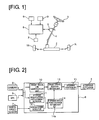
- FIG. 1 is a schematic diagram showing a vehicle steering system to which a vehicle travel assistance device according to a first embodiment is applied.
- the vehicle steering system according to the first embodiment is provided with: left and right front wheels 1L, 1R, a steering gear 2, a steering wheel 3, a steering shaft 4, a steering actuator 5, a control unit 6, wheel speed sensors 7, a camera 8, and a GPS receiver 9.
- the steering gear 2 converts a rotation motion, which is inputted into the steering shaft 4 by the driver performing a rotation operation on the steering wheel 3, into a parallel motion in the vehicle width direction, and steers the left and right front wheels 1L, 1R.
- the steering actuator 5 is, e.g., an electric motor, and outputs a torque into the steering shaft 4 and steers the left and right front wheels 1L, 1R.
- the wheel speed sensors 7 are provided to each wheel and detect the rotation speeds of the wheels.
- the camera 8 images the front of the host vehicle.
- the GPS receiver 9 receives a signal from a GPS satellite, references a map database, and detects the host vehicle position.
- control unit 6 which drives the steering actuator 5 on the basis of a predetermined control logic, and performs travel assistance.
- the control unit 6 performs a steering control, as travel assistance, when the travel line of the host vehicle deviates from the target travel line.
- the steering control sets a target travel position (forward watch point) on the travel path set apart by a forward watch point distance in front of the host vehicle, and drives the steering actuator 5 and steering the left and right front wheels 1L, 1R so that the vehicle travels to the target travel position.
- FIG. 2 is a control block diagram for the control unit 6 according to the first embodiment.
- the control unit 6 is provided with a target travel line identification unit 10, an attitude angle/lateral displacement detector (lateral displacement detection means) 11, a vehicle speed detector 12, a target travel position setting unit 13, a forward watch point distance setting unit (watch point distance setting means) 14, and a steering controller 15.
- the control unit 6 executes the steering control described below.
- the target travel line identification unit 10 identifies the target travel line on the basis of an imaged image obtained from the camera 8 and the host vehicle position information obtained from the GPS receiver 9.
- the attitude angle/lateral displacement detector 11 calculates an attitude angle ⁇ in relation to the travel path and the lateral displacement y of the host vehicle from the target travel line on the basis of the image captured from the camera 8 and the host vehicle position information obtained from the GPS receiver 9.
- the attitude angle ⁇ is an angle formed by a vehicle axial line (straight line extending in the vehicle longitudinal direction through the lateral center position of the host vehicle) with respect to a straight line parallel to a tangent of the target travel line passing through the lateral center position of the host vehicle (hereafter referred to the tangent of the target travel line).
- the attitude angle ⁇ is deemed to have a positive (+) sign when the vehicle axial line is oriented laterally outwards with respect to the travel path in relation to the tangent of the target travel line, and deemed to have a negative (-) sign when the vehicle axial line is oriented towards the center of the travel path in relation to the tangent of the target travel line.
- the vehicle speed detector 12 detects the body speed (vehicle speed) V on the basis of signals from the wheel speed sensors 7.
- the method for calculating the vehicle speed V is arbitrary.
- the vehicle speed V may be an average value of the wheel speeds of the four wheels, or an average value of the wheel speeds of left and right rear wheels which are driven wheels.
- the target travel position setting unit 13 calculates, as a target travel position P, a position on the target travel line set apart by a forward watch point distance Ls from the host vehicle.
- the forward watch point distance setting unit 14 is provided with an attitude determining unit 14a (attitude determining means) for determining the orientation of the host vehicle in relation to the travel path from the attitude angle ⁇ , and is adapted to set the forward watch point distance Ls on the basis of the orientation of the host vehicle in relation to the travel path, the vehicle speed V, and the lateral displacement y.
- attitude determining unit 14a attitude determining means
- the steering controller 15 calculates a target curve linking the host vehicle position and the target travel position P, calculates an amount of steering control to be performed on the left and right front wheels 1L, 1R on the basis of the target curve, and drives the steering actuator 5 on the basis of the amount of steering control.
- FIG. 3 is a flow chart showing the flow of a steering control process executed by the control unit 6 according to the first embodiment. Each of the steps will now be described.
- step S1 the vehicle speed detector 12 reads the sensor signals from the wheel speed sensors 7, and the target travel line identification unit 10 and the attitude angle/lateral displacement detector 11 reads an imaged image from the camera 8 and the host vehicle position information from the GPS receiver 9.
- step S2 the target travel line identification unit 10 identifies the target travel line on the basis of the imaged image obtained from the camera 8 and the host vehicle position information obtained from the GPS receiver 9.
- step S3 the attitude angle/lateral displacement detector 11 calculates the vehicle attitude angle ⁇ in relation to the travel path and the lateral displacement y of the host vehicle from the target travel line on the basis of the imaged image obtained from the camera 8 and the host vehicle position information obtained from the GPS receiver 9.
- step S4 the attitude determining unit 14a determines the orientation of the host vehicle in relation to the travel path from the attitude angle ⁇ . If the sign of the attitude angle ⁇ is positive (+), the host vehicle is determined to be oriented outwards with respect to the travel path. If the sign of the attitude angle ⁇ is negative (-), the host vehicle is determined to be oriented towards the center of the travel path. If the attitude angle ⁇ is zero, the orientation of the host vehicle is determined to be parallel to the travel path.
- step S5 the forward watch point distance setting unit 14 sets the forward watch point distance Ls on the basis of the vehicle speed V, the lateral displacement y, and the orientation of the host vehicle in relation to the travel path.
- the method for setting the forward watch point distance Ls will be described further below.
- step S6 the target travel position setting unit 13 calculates a position on the target travel line set apart by the forward watch point distance Ls from the host vehicle as the target travel position P.
- step S7 the steering controller 15 calculates a target curve linking the host vehicle position and the target travel position P at a constant curvature, and calculates an amount of steering control to be performed on the left and right front wheels 1L, 1R corresponding to the target curve.
- the amount of steering control calculated may be such that the target curve is followed. It is also possible to provide a torque sensor on the steering shaft 4, detect a steering intervention performed by the driver, and set the amount of steering control to zero when steering intervention is performed, or apply an operation torque so as to guide the steering operation performed by the driver until the steering angle of the left and right front wheels 1L, 1R is such that the target curve is followed.
- step S8 the steering controller 15 drives the steering actuator 5 on the basis of the amount of steering control.
- FIG.4 shows the host vehicle position, the target travel line, the lateral displacement y, the attitude angle ⁇ , the forward watch point distance Ls, the target travel position P, and the target curve in the steering control according to the first embodiment.
- the forward watch point distance setting unit 14 calculates a forward watch point distance base value Ls_base on the basis of the vehicle speed V.
- the base value Ls_base is obtained by multiplying the vehicle speed V with a predetermined time constant set in advance.
- the forward watch point distance base value Ls_base is reduced or increased on the basis of the attitude angle ⁇ and the lateral displacement y. Specifically, if the lateral displacement y is equal to or greater than a lateral displacement threshold value y_th, the forward watch point distance base value Ls_base is not changed, and if the lateral displacement y is equal to or greater than the lateral displacement threshold value y_th the forward watch point distance base value Ls_base is changed according to the attitude angle ⁇ .
- FIG.5 is a time chart showing the operation control action and a schematic diagram showing the vehicle state according to the first embodiment when the driver performs a steering intervention on a straight road.
- the steering angle ⁇ of the left and right front wheels 1L, 1R and the lateral displacement y are deemed to be positive (+) on the left side and negative (-) on the right side.
- the attitude angle ⁇ is deemed to be positive (+) when, relative to the tangent m of the target travel line, the vehicle axial line n is oriented laterally outwards with respect to the travel path and negative (-) when the vehicle axial line n is oriented towards the center of the travel path.
- the vehicle Prior to time t1, the vehicle is travelling along the target travel line.
- the steering angle ⁇ begins to increase due to steering intervention performed by the driver, accompanied by an increase in the attitude angle ⁇ and the lateral displacement y.
- the lateral displacement y remains below the lateral displacement threshold value y_th, and the forward watch point distance Ls therefore remains at the forward watch point distance base value Ls_base.
- the lateral displacement y becomes equal to or greater than the lateral displacement threshold value y_th, and the forward watch point distance Ls is therefore reduced so as to be smaller than the base value Ls_base.
- the steering intervention performed by the driver is discontinued and the steering angle ⁇ begins to decrease, and the attitude angle ⁇ begins to decrease.
- the attitude angle ⁇ changes from positive to negative, and the forward watch point distance Ls is therefore increased so as to be greater than the base value Ls_base.
- the forward watch point distance Ls returns to the forward watch point distance base value Ls_base.
- the forward watch point distance is increased so as to be greater when the lateral displacement of the vehicle is greater.
- the forward watch point distance is increased in correspondence with the lateral displacement when the vehicle is travelling around a curve having a small curvature radius, the risk of lane departure increases.
- the forward watch point distance Ls obtained by reducing the forward watch point distance base value Ls_base is set if the host vehicle is oriented outwards with respect to the travel path. Reducing the forward watch point distance results in the target curve corresponding to the target travel position P being positioned nearer the host vehicle.
- the target curve having a smaller curvature radius increases the amount of steering control that must be performed on the left and right front wheels 1L, 1R in order to follow the target curve. In other words, the control gain for the steering control is increased.
- the host vehicle being oriented outwards with respect to the travel path signifies that the host vehicle is facing a direction that diverges away from the target travel line and that the risk of lane departure is higher. Therefore, in such an instance, reducing the forward watch point distance and increasing the control gain for the steering control makes it possible to eliminate the lane-departing trend of the vehicle at an early stage and inhibit lane departure.
- the forward watch point distance is reduced so as to be smaller when the curvature radius of the travel path is smaller.
- uniformly reducing the forward watch point distance even when the risk of lane departure is lower result in an excessively strong control gain in the steering control and a significant change in vehicle behavior, imparting the driver with a sense of unease.
- a forward watch point distance Ls obtained by increasing the forward watch point distance base value Ls_base is set.
- Increasing the forward watch point distance results in the target travel position P being positioned further from the host vehicle.
- the target curve having a larger curvature radius reduces the amount of steering control that must be performed on the left and right front wheels 1L, 1R in order to follow the target curve. In other words, the control gain for the steering control is reduced.
- the host vehicle being oriented towards the center of the travel path signifies that the host vehicle is facing a direction returning to the target travel line and that the risk of lane departure is lower. Therefore, in such an instance, extending the forward watch point distance and reducing the control gain for the steering control makes it possible to suppress the change in vehicle behavior and reduce the sense of unease imparted to the driver.
- the return to the target travel line is performed at a gradual pace while a further deviation from the target travel line is suppressed, resulting in a movement that matches the driving sensation experienced by the driver.
- the steering reaction force is greater during a deviation from the target travel line and smaller during a return to the target travel line, making it possible to reduce the sense of unease imparted to the driver.
- the forward watch point distance Ls is reduced so as to be smaller than the base value Ls_base, and if the lateral displacement y is less than the lateral displacement threshold value y_th, the forward watch point distance Ls is kept at the base value Ls_base.
- Lane departure is caused not only due to a movement of deviating from the target, i.e., the orientation of the vehicle, but also due to the amount of deviation from the target, i.e., the lateral displacement y.
- the risk of lane departure is higher in an instance in which the lateral displacement y is greater than in an instance in which the lateral displacement y is smaller.
- the lateral displacement y is greater, reducing the forward watch point distance Ls makes it possible to inhibit lane departure in a more reliable manner. If the lateral displacement y is smaller, avoiding a reduction in the forward watch point distance Ls makes it possible to minimize the control gain when the risk of lane departure is lower and to reduce the sense of unease imparted to the driver.
- the forward watch point distance Ls is extended so as to be greater than the base value Ls_base, and if the lateral displacement y is less than the lateral displacement threshold value y_th, the forward watch point distance Ls is kept at the base value Ls_base.
- the control gain for the steering control for returning the vehicle to the target travel line is smaller irrespective of the forward watch point distance Ls. Therefore, in such an instance, preventing the forward watch point distance Ls from increasing makes it possible to return the vehicle to the target travel line at an early stage. In contrast, when the lateral displacement y is greater, the control gain is larger. Therefore, in such an instance, increasing the forward watch point distance Ls makes it possible to minimize the control gain and reduce the sense of unease imparted to the driver.
- the vehicle travel assistance device has the following effects.
- the second embodiment is an example in which the forward watch point distance Ls is set on the basis of the distance to a road boundary line in front of the vehicle. A description will be given for portions that differ from the first embodiment.
- the attitude angle/lateral displacement detector (boundary line distance detection means) 11 calculates, in addition to the vehicle attitude angle ⁇ in relation to the travel path and the lateral displacement y of the host vehicle from the target travel line, the distance Ld to the road boundary line in front of the vehicle, on the basis of the imaged image obtained from the camera 8 and the host vehicle position information obtained from the GPS receiver 9.
- the forward watch point distance setting unit 14 sets the forward watch point distance Ls on the basis of the vehicle speed V, the lateral displacement y, the attitude angle ⁇ , and the distance Ld to the road boundary line in front of the vehicle.
- the steering control process according to the second embodiment is substantially identical to the steering control process according to the first embodiment shown in FIG.3 , but is different in that the distance Ld to the road boundary line in front of the vehicle is calculated in step S3, and in that the forward watch point distance Ls is set on the basis of the vehicle speed V, the lateral displacement y, the attitude angle ⁇ , and the distance Ld to the road boundary line in front of the vehicle in step S4.
- a forward watch point distance base value Ls_base corresponding to the vehicle speed V is calculated, and the base value Ls_base is changed according to the lateral displacement y and the orientation of the attitude angle ⁇ .
- the forward watch point distance Ls which is set according to the lateral displacement y and the orientation of the attitude angle ⁇ , is set to distance Ld.
- the forward watch point distance Ls remains at the value obtained by changing the base value Ls_base according to the lateral displacement y and the orientation of the host vehicle in relation to the travel path as shown in FIG. 7(a) .
- the forward watch point distance Ls is set to distance Ld as shown in FIG. 7(b) .
- the forward watch point distance Ls is reduced, whereby lane departure can be inhibited in a more reliable manner. Setting the forward watch point distance Ls to the distance Ld in this instance makes it possible to set an appropriate target travel position P which prevents departure from the travel path.
- the vehicle travel assistance device has the following effects in addition to the effects (1) to (4) of the first embodiment.
- the forward watch point distance base value Ls_base may be reduced or extended solely on the basis of the orientation of the host vehicle in relation to the travel path.
- the proportion of reduction or extension may be varied according to the attitude angle ⁇ , the lateral displacement y, or the distance Ld to the road boundary line in front of the vehicle. For example, in the case in which attitude angle ⁇ is used, the proportion of reduction or extension may be made to be greater when the absolute value
Landscapes
- Engineering & Computer Science (AREA)
- Transportation (AREA)
- Mechanical Engineering (AREA)
- Chemical & Material Sciences (AREA)
- Combustion & Propulsion (AREA)
- Steering Control In Accordance With Driving Conditions (AREA)
- Automation & Control Theory (AREA)
- Traffic Control Systems (AREA)
Abstract
Description
- The present invention relates to a vehicle travel assistance device.
-
Patent Citation 1 discloses a technique in which the forward watch point distance determining the target travel position for steering control is set so as to be greater when the amount by which a vehicle is offset from the travel path center position is larger. -
Patent Citation 2 discloses a technique in which the forward watch point distance is set so as to be smaller when the curvature radius of the travel path is smaller. -
- Patent Citation 1: Japanese Laid-Open Patent Application No.
2010-76573 - Patent Citation 2: Japanese Laid-Open Patent Application No.
10-167100 - However, in the technique disclosed in
Patent Citation 1, in a case in which the travel path curves at a small curvature radius and the offset amount is larger, the forward watch point distance is set so as to be greater irrespective of the curvature radius, increasing the likelihood of lane departure. - In the technique disclosed in
Patent Citation 2, the forward watch point distance is set so as to be smaller when the travel path is curved at a small curvature radius even when the likelihood of lane departure is small, resulting in a significant change in vehicle behavior and thereby imparting the driver with a sense of unease. - An object of the present invention is to provide a vehicle travel assistance device capable of both inhibiting lane departure and reducing the sense of unease imparted to the driver.
- In order to achieve the above object, in the present invention, the forward watch point distance is set so as to be smaller when the host vehicle is oriented outwards with respect to the travel path than when the host vehicle is parallel to the travel path.
- The likelihood of lane departure is higher when the host vehicle is oriented outwards with respect to the travel path and the likelihood of lane departure is lower when the host vehicle is not oriented outwards with respect to the travel path. Accordingly, when the host vehicle is oriented outwards with respect to the travel path, reducing the forward watch point distance makes it possible to inhibit lane departure, and when the host vehicle is not oriented outwards with respect to the travel path, avoiding a reduction in the forward watch point distance makes it possible to reduce the sense of unease imparted to the driver.
- As a result, it is possible to both inhibit lane departure and reduce the sense of unease imparted to the driver.
-
-
FIG. 1 is a schematic diagram showing a vehicle steering system to which a vehicle travel assistance device according to a first embodiment is applied; -
FIG. 2 is a control block diagram for acontrol unit 6 according to the first embodiment; -
FIG. 3 is a flow chart showing the flow of a steering control process executed by thecontrol unit 6 according to the first embodiment; -
FIG. 4 is a schematic diagram showing the control method and parameters for the steering control according to the first embodiment; -
FIG. 5 is a time chart showing the operation control action and a schematic diagram showing the vehicle state according to the first embodiment when the driver performs a steering intervention on a straight road; -
FIG. 6 is a schematic diagram showing the action of setting a forward watch point distance Ls according to the attitude angle ϕ according to the first embodiment; and -
FIG. 7 is a schematic diagram showing the action of setting the forward watch point distance Ls according to the distance Ld to the road boundary according to a second embodiment. -
- 1L, 1R
- Left and right front wheels
- 2
- Steering gear
- 3
- Steering wheel
- 4
- Steering shaft
- 5
- Steering actuator
- 6
-
Control unit 6 - 7
- Wheel speed sensor
- 8
- Camera
- 9
- GPS receiver
- 10
- Target travel line identification unit
- 11
- Attitude angle/lateral displacement detector (lateral displacement detection means, boundary line distance detection means)
- 12
- Vehicle speed detector
- 13
- Target travel position setting unit
- 14
- Forward watch point distance setting unit
- 14a
- Attitude determining unit (attitude determining means)
- 15
- Steering controller
- A preferred embodiment of the drive force transmission device of the present invention will now be described with reference to embodiments illustrated in the accompanying drawings.
-
FIG. 1 is a schematic diagram showing a vehicle steering system to which a vehicle travel assistance device according to a first embodiment is applied. The vehicle steering system according to the first embodiment is provided with: left and rightfront wheels steering gear 2, asteering wheel 3, asteering shaft 4, asteering actuator 5, acontrol unit 6,wheel speed sensors 7, acamera 8, and aGPS receiver 9. - The
steering gear 2 converts a rotation motion, which is inputted into thesteering shaft 4 by the driver performing a rotation operation on thesteering wheel 3, into a parallel motion in the vehicle width direction, and steers the left and rightfront wheels - The
steering actuator 5 is, e.g., an electric motor, and outputs a torque into thesteering shaft 4 and steers the left and rightfront wheels - The
wheel speed sensors 7 are provided to each wheel and detect the rotation speeds of the wheels. - The
camera 8 images the front of the host vehicle. - The
GPS receiver 9 receives a signal from a GPS satellite, references a map database, and detects the host vehicle position. - Information from the
wheel speed sensors 7, thecamera 8, and theGPS receiver 9 is inputted into thecontrol unit 6, which drives thesteering actuator 5 on the basis of a predetermined control logic, and performs travel assistance. - In order that the host vehicle travels along a target travel line at the lane-width center of a travel path, the
control unit 6 performs a steering control, as travel assistance, when the travel line of the host vehicle deviates from the target travel line. The steering control sets a target travel position (forward watch point) on the travel path set apart by a forward watch point distance in front of the host vehicle, and drives thesteering actuator 5 and steering the left and rightfront wheels -
FIG. 2 is a control block diagram for thecontrol unit 6 according to the first embodiment. Thecontrol unit 6 is provided with a target travelline identification unit 10, an attitude angle/lateral displacement detector (lateral displacement detection means) 11, avehicle speed detector 12, a target travelposition setting unit 13, a forward watch point distance setting unit (watch point distance setting means) 14, and asteering controller 15. Thecontrol unit 6 executes the steering control described below. - The target travel
line identification unit 10 identifies the target travel line on the basis of an imaged image obtained from thecamera 8 and the host vehicle position information obtained from theGPS receiver 9. - The attitude angle/
lateral displacement detector 11 calculates an attitude angle ϕ in relation to the travel path and the lateral displacement y of the host vehicle from the target travel line on the basis of the image captured from thecamera 8 and the host vehicle position information obtained from theGPS receiver 9. The attitude angle ϕ is an angle formed by a vehicle axial line (straight line extending in the vehicle longitudinal direction through the lateral center position of the host vehicle) with respect to a straight line parallel to a tangent of the target travel line passing through the lateral center position of the host vehicle (hereafter referred to the tangent of the target travel line). The attitude angle ϕ is deemed to have a positive (+) sign when the vehicle axial line is oriented laterally outwards with respect to the travel path in relation to the tangent of the target travel line, and deemed to have a negative (-) sign when the vehicle axial line is oriented towards the center of the travel path in relation to the tangent of the target travel line. - The
vehicle speed detector 12 detects the body speed (vehicle speed) V on the basis of signals from thewheel speed sensors 7. The method for calculating the vehicle speed V is arbitrary. For example, the vehicle speed V may be an average value of the wheel speeds of the four wheels, or an average value of the wheel speeds of left and right rear wheels which are driven wheels. - The target travel
position setting unit 13 calculates, as a target travel position P, a position on the target travel line set apart by a forward watch point distance Ls from the host vehicle. - The forward watch point distance setting unit 14 is provided with an
attitude determining unit 14a (attitude determining means) for determining the orientation of the host vehicle in relation to the travel path from the attitude angle ϕ, and is adapted to set the forward watch point distance Ls on the basis of the orientation of the host vehicle in relation to the travel path, the vehicle speed V, and the lateral displacement y. - The steering
controller 15 calculates a target curve linking the host vehicle position and the target travel position P, calculates an amount of steering control to be performed on the left and rightfront wheels steering actuator 5 on the basis of the amount of steering control. -
FIG. 3 is a flow chart showing the flow of a steering control process executed by thecontrol unit 6 according to the first embodiment. Each of the steps will now be described. - In step S1, the
vehicle speed detector 12 reads the sensor signals from thewheel speed sensors 7, and the target travelline identification unit 10 and the attitude angle/lateral displacement detector 11 reads an imaged image from thecamera 8 and the host vehicle position information from theGPS receiver 9. - In step S2, the target travel
line identification unit 10 identifies the target travel line on the basis of the imaged image obtained from thecamera 8 and the host vehicle position information obtained from theGPS receiver 9. - In step S3, the attitude angle/
lateral displacement detector 11 calculates the vehicle attitude angle ϕ in relation to the travel path and the lateral displacement y of the host vehicle from the target travel line on the basis of the imaged image obtained from thecamera 8 and the host vehicle position information obtained from theGPS receiver 9. - In step S4, the
attitude determining unit 14a determines the orientation of the host vehicle in relation to the travel path from the attitude angle ϕ. If the sign of the attitude angle ϕ is positive (+), the host vehicle is determined to be oriented outwards with respect to the travel path. If the sign of the attitude angle ϕ is negative (-), the host vehicle is determined to be oriented towards the center of the travel path. If the attitude angle ϕ is zero, the orientation of the host vehicle is determined to be parallel to the travel path. - In step S5, the forward watch point distance setting unit 14 sets the forward watch point distance Ls on the basis of the vehicle speed V, the lateral displacement y, and the orientation of the host vehicle in relation to the travel path. The method for setting the forward watch point distance Ls will be described further below.
- In step S6, the target travel
position setting unit 13 calculates a position on the target travel line set apart by the forward watch point distance Ls from the host vehicle as the target travel position P. - In step S7, the steering
controller 15 calculates a target curve linking the host vehicle position and the target travel position P at a constant curvature, and calculates an amount of steering control to be performed on the left and rightfront wheels steering shaft 4, detect a steering intervention performed by the driver, and set the amount of steering control to zero when steering intervention is performed, or apply an operation torque so as to guide the steering operation performed by the driver until the steering angle of the left and rightfront wheels - In step S8, the steering
controller 15 drives thesteering actuator 5 on the basis of the amount of steering control. -
FIG.4 shows the host vehicle position, the target travel line, the lateral displacement y, the attitude angle ϕ, the forward watch point distance Ls, the target travel position P, and the target curve in the steering control according to the first embodiment. - The forward watch point distance setting unit 14 calculates a forward watch point distance base value Ls_base on the basis of the vehicle speed V. The base value Ls_base is obtained by multiplying the vehicle speed V with a predetermined time constant set in advance.
- In the first embodiment, the forward watch point distance base value Ls_base is reduced or increased on the basis of the attitude angle ϕ and the lateral displacement y. Specifically, if the lateral displacement y is equal to or greater than a lateral displacement threshold value y_th, the forward watch point distance base value Ls_base is not changed, and if the lateral displacement y is equal to or greater than the lateral displacement threshold value y_th the forward watch point distance base value Ls_base is changed according to the attitude angle ϕ.
- 1. If the host vehicle is oriented outwards with respect to the travel path
If the host vehicle is oriented outwards with respect to the travel path, the forward watch point distance base value Ls_base is reduced by a proportion set in advance. - 2. If the host vehicle is oriented towards the center of the travel path
If the host vehicle is oriented towards the center of the travel path, the forward watch point distance base value Ls_base is increased by a proportion set in advance. - 3. If the orientation of the host vehicle is parallel to the travel path
If the orientation of the host vehicle is parallel to the travel path, the forward watch point distance base value Ls_base is not changed. In other words, if the host vehicle is oriented outwards with respect to the travel path, the forward watch point distance setting unit 14 reduces the forward watch point distance so as to be smaller than when the host vehicle is oriented along the travel path. If the host vehicle is oriented towards the center of the travel path, the forward watch point distance setting unit 14 increases the forward watch point distance so as to be greater than when the host vehicle is oriented along the travel path. If the host vehicle is oriented outwards with respect to the travel path, the forward watch point distance setting unit 14 reduces the forward watch point distance so as to be smaller than when the host vehicle is oriented towards the center of the travel path. - The action of the present embodiment will now be described.
-
FIG.5 is a time chart showing the operation control action and a schematic diagram showing the vehicle state according to the first embodiment when the driver performs a steering intervention on a straight road. InFIG.5 , the steering angle θ of the left and rightfront wheels - Prior to time t1, the vehicle is travelling along the target travel line.
- At time t1, the steering angle θ begins to increase due to steering intervention performed by the driver, accompanied by an increase in the attitude angle ϕ and the lateral displacement y. However, the lateral displacement y remains below the lateral displacement threshold value y_th, and the forward watch point distance Ls therefore remains at the forward watch point distance base value Ls_base.
- At time t2, the lateral displacement y becomes equal to or greater than the lateral displacement threshold value y_th, and the forward watch point distance Ls is therefore reduced so as to be smaller than the base value Ls_base.
- At time t3, the steering intervention performed by the driver is discontinued and the steering angle θ begins to decrease, and the attitude angle ϕ begins to decrease.
- At time t4, the attitude angle ϕ changes from positive to negative, and the forward watch point distance Ls is therefore increased so as to be greater than the base value Ls_base.
- At time t5, the lateral displacement y falls below the lateral displacement threshold value y_th. Therefore, the forward watch point distance Ls returns to the forward watch point distance base value Ls_base.
- At time t6, the vehicle returns onto the target travel line.
- In the technique disclosed in
JP-A 2010-76573 - In contrast, in the first embodiment, as shown in
FIG. 6(a) , the forward watch point distance Ls obtained by reducing the forward watch point distance base value Ls_base is set if the host vehicle is oriented outwards with respect to the travel path. Reducing the forward watch point distance results in the target curve corresponding to the target travel position P being positioned nearer the host vehicle. In this instance, the target curve having a smaller curvature radius increases the amount of steering control that must be performed on the left and rightfront wheels - In other words, the host vehicle being oriented outwards with respect to the travel path signifies that the host vehicle is facing a direction that diverges away from the target travel line and that the risk of lane departure is higher. Therefore, in such an instance, reducing the forward watch point distance and increasing the control gain for the steering control makes it possible to eliminate the lane-departing trend of the vehicle at an early stage and inhibit lane departure.
- Accordingly, even if the vehicle attitude deviates from the target travel line due to a steering intervention performed by the driver or another cause on a curve having a small curvature radius, it is possible to promptly restore the attitude, making it possible to inhibit lane departure.
- In the technique disclosed in
JP-A 10-167100 - In contrast, in the first embodiment, as shown in
FIG. 6(b) , when the host vehicle is oriented towards the center of the travel path, a forward watch point distance Ls obtained by increasing the forward watch point distance base value Ls_base is set. Increasing the forward watch point distance results in the target travel position P being positioned further from the host vehicle. In this instance, the target curve having a larger curvature radius reduces the amount of steering control that must be performed on the left and rightfront wheels - In other words, the host vehicle being oriented towards the center of the travel path signifies that the host vehicle is facing a direction returning to the target travel line and that the risk of lane departure is lower. Therefore, in such an instance, extending the forward watch point distance and reducing the control gain for the steering control makes it possible to suppress the change in vehicle behavior and reduce the sense of unease imparted to the driver.
- Accordingly, it is possible, on a curve having a small curvature radius, to inhibit the forward watch point distance from being reduced unnecessarily, and to reduce the sense of unease imparted to the driver.
- In the steering control according to the first embodiment, instead of the target travel line being uniformly tracked, the return to the target travel line is performed at a gradual pace while a further deviation from the target travel line is suppressed, resulting in a movement that matches the driving sensation experienced by the driver.
- It is therefore possible to suppress a sudden change in vehicle behavior during a return to the target travel line after a steering intervention performed by the driver or at the start of steering control from a position set apart from the target travel line, and to reduce the sense of unease imparted to the driver.
- In addition, when the driver performs a steering operation, the steering reaction force is greater during a deviation from the target travel line and smaller during a return to the target travel line, making it possible to reduce the sense of unease imparted to the driver.
- In the first embodiment, when the host vehicle is oriented outwards with respect to the travel path, if the lateral displacement y is equal to or greater than the lateral displacement threshold value y_th, the forward watch point distance Ls is reduced so as to be smaller than the base value Ls_base, and if the lateral displacement y is less than the lateral displacement threshold value y_th, the forward watch point distance Ls is kept at the base value Ls_base.
- Lane departure is caused not only due to a movement of deviating from the target, i.e., the orientation of the vehicle, but also due to the amount of deviation from the target, i.e., the lateral displacement y. The risk of lane departure is higher in an instance in which the lateral displacement y is greater than in an instance in which the lateral displacement y is smaller.
- Accordingly, if the lateral displacement y is greater, reducing the forward watch point distance Ls makes it possible to inhibit lane departure in a more reliable manner. If the lateral displacement y is smaller, avoiding a reduction in the forward watch point distance Ls makes it possible to minimize the control gain when the risk of lane departure is lower and to reduce the sense of unease imparted to the driver.
- In the first embodiment, when the host vehicle is oriented towards the center of the travel path, if the lateral displacement y is equal to or greater than the lateral displacement threshold value y_th, the forward watch point distance Ls is extended so as to be greater than the base value Ls_base, and if the lateral displacement y is less than the lateral displacement threshold value y_th, the forward watch point distance Ls is kept at the base value Ls_base.
- When the lateral displacement y is smaller, the control gain for the steering control for returning the vehicle to the target travel line is smaller irrespective of the forward watch point distance Ls. Therefore, in such an instance, preventing the forward watch point distance Ls from increasing makes it possible to return the vehicle to the target travel line at an early stage. In contrast, when the lateral displacement y is greater, the control gain is larger. Therefore, in such an instance, increasing the forward watch point distance Ls makes it possible to minimize the control gain and reduce the sense of unease imparted to the driver.
- The effects of the present embodiment will now be described.
- The vehicle travel assistance device according to the first embodiment has the following effects.
- (1) A vehicle travel assistance device for setting a target travel position P set apart by a forward watch point distance Ls in front of a host vehicle on a travel path and assisting the travel of the host vehicle so that the host vehicle travels through the set target travel position P, the vehicle travel assistance device being provided with: an
attitude determining unit 14a for determining the orientation of the host vehicle in relation to the travel path; and a watch point distance setting unit 14 for setting, when the host vehicle is oriented outwards with respect to the travel path, a forward watch point distance Ls obtained by reducing a forward watch point distance base value Ls_base so as to be smaller than when the orientation of the host vehicle is parallel to the travel path. It is thereby possible to both inhibit lane departure and reduce the sense of unease imparted on the driver. - (2) A vehicle travel assistance device for setting a target travel position P set apart by a forward watch point distance Ls in front of a host vehicle on a travel path and assisting the travel of the host vehicle so that the host vehicle travels through the set target travel position P, the vehicle travel assistance device being provided with: an
attitude determining unit 14a for determining the orientation of the host vehicle in relation to the travel path; and a forward watch point distance setting unit 14 for setting, when the host vehicle is oriented towards the center of the travel path, a forward watch point distance Ls obtained by extending the forward watch point distance base value Ls_base so as to be greater than when the orientation of the host vehicle is parallel to the travel path. It is thereby possible to both inhibit lane departure and reduce the sense of unease imparted on the driver. - (3) An attitude angle/
lateral displacement detector 11 for detecting the lateral displacement y of the host vehicle from a target travel line is provided, and when the host vehicle is oriented outwards with respect to the travel path and the detected lateral displacement y is equal to or greater than a lateral displacement threshold value y_th, the forward watch point distance setting unit 14 sets a forward watch point distance Ls so as to be smaller than when the lateral displacement y is smaller than the lateral displacement threshold value y_th. It is thereby possible to both inhibit lane departure and reduce the sense of unease imparted on the driver in a more reliable manner. - (4) An attitude angle/
lateral displacement detector 11 for detecting the lateral displacement y of the host vehicle from a target travel line is provided, and when the host vehicle is oriented towards the center of the travel path and the detected lateral displacement y is equal to or greater than a lateral displacement threshold value y_th, the forward watch point distance setting unit 14 sets a forward watch point distance Ls so as to be greater than when the lateral displacement y is smaller than the lateral displacement threshold value y_th. It is thereby possible to both return the vehicle to the target travel line and reduce the sense of unease imparted on the driver. - The second embodiment is an example in which the forward watch point distance Ls is set on the basis of the distance to a road boundary line in front of the vehicle. A description will be given for portions that differ from the first embodiment.
- The attitude angle/lateral displacement detector (boundary line distance detection means) 11 calculates, in addition to the vehicle attitude angle ϕ in relation to the travel path and the lateral displacement y of the host vehicle from the target travel line, the distance Ld to the road boundary line in front of the vehicle, on the basis of the imaged image obtained from the
camera 8 and the host vehicle position information obtained from theGPS receiver 9. - The forward watch point distance setting unit 14 sets the forward watch point distance Ls on the basis of the vehicle speed V, the lateral displacement y, the attitude angle ϕ, and the distance Ld to the road boundary line in front of the vehicle.
- The steering control process according to the second embodiment is substantially identical to the steering control process according to the first embodiment shown in
FIG.3 , but is different in that the distance Ld to the road boundary line in front of the vehicle is calculated in step S3, and in that the forward watch point distance Ls is set on the basis of the vehicle speed V, the lateral displacement y, the attitude angle ϕ, and the distance Ld to the road boundary line in front of the vehicle in step S4. - As with the first embodiment, a forward watch point distance base value Ls_base corresponding to the vehicle speed V is calculated, and the base value Ls_base is changed according to the lateral displacement y and the orientation of the attitude angle ϕ.
- In the second embodiment, additionally, if the distance Ld to the road boundary line in front of the vehicle is equal to or smaller than a boundary line distance threshold value Ld_th, the forward watch point distance Ls, which is set according to the lateral displacement y and the orientation of the attitude angle ϕ, is set to distance Ld.
- The action of the present embodiment will now be described.
- In the second embodiment, if the distance Ld to the road boundary line in front of the vehicle exceeds the boundary line distance threshold value Ld_th, the forward watch point distance Ls remains at the value obtained by changing the base value Ls_base according to the lateral displacement y and the orientation of the host vehicle in relation to the travel path as shown in
FIG. 7(a) . On the other hand, if the distance Ld to the road boundary line in front of the vehicle is equal to or less than the boundary line distance threshold value Ld_th, the forward watch point distance Ls is set to distance Ld as shown inFIG. 7(b) . - In particular, in a curve having a small curvature radius, even when the vehicle is travelling along the target travel line, if the distance Ld to the road boundary line in front of the vehicle is small, the risk of lane departure is higher. In such an instance, there is a possibility that setting the forward watch point distance Ls on the basis of the lateral displacement y and the orientation of the host vehicle in relation to the travel path will not make it possible to prevent lane departure.
- Accordingly, in the second embodiment, if the distance Ld is equal to or smaller than the boundary line distance threshold value Ld_th, the forward watch point distance Ls is reduced, whereby lane departure can be inhibited in a more reliable manner. Setting the forward watch point distance Ls to the distance Ld in this instance makes it possible to set an appropriate target travel position P which prevents departure from the travel path.
- In addition, adding a configuration in which the forward watch point distance Ls is restricted to the distance Ld to the road boundary line when Ld ≤ Ld th makes it possible to sufficiently deal with a curve having a small curvature radius. This makes it possible to increase the forward watch point distance base value Ls_base corresponding to the vehicle speed V, resulting in an effect of making it possible to further reduce the sense of unease imparted on the driver.
- The effects of the present embodiment will now be described.
- The vehicle travel assistance device according to the second embodiment has the following effects in addition to the effects (1) to (4) of the first embodiment.
- (5) An attitude angle/lateral displacement detector (boundary line distance detection means) 11 for detecting the distance Ld to the road boundary line in front of the vehicle is provided. If the detected distance Ld to the road boundary line is equal to or smaller than the boundary line distance threshold value Ld_th, the forward watch point distance setting unit 14 reduces the forward watch point distance Ls so as to be smaller than when the distance Ld to the road boundary line exceeds the boundary line distance threshold value Ld_th. It is thereby possible to inhibit lane departure in a curve having a small curvature radius in a more reliable manner. In addition, it is possible to set a greater forward watch point distance base value Ls_base, making it possible to further reduce the sense of unease imparted to the driver.
- (6) If the detected distance Ld to the road boundary line is equal to or smaller than the boundary line distance threshold value Ld_th, the forward watch point distance setting unit 14 sets the forward watch point distance Ls so as to be equal to the distance Ld to the road boundary line, making it possible to set an appropriate target travel position P which prevents departure from the travel path.
- Embodiments for carrying out the present invention have been described above with reference to embodiments. However, the specific configuration of the present invention is not limited to that in the embodiments, and design changes and other modifications that do not depart from the scope of the invention are also included in the present invention.
- For example, the forward watch point distance base value Ls_base may be reduced or extended solely on the basis of the orientation of the host vehicle in relation to the travel path.
- When reducing or extending the forward watch point distance base value Ls_base, the proportion of reduction or extension may be varied according to the attitude angle ϕ, the lateral displacement y, or the distance Ld to the road boundary line in front of the vehicle. For example, in the case in which attitude angle ϕ is used, the proportion of reduction or extension may be made to be greater when the absolute value |ϕ| of the attitude angle ϕ is greater.
Claims (6)
- A vehicle travel assistance device for setting a target travel position set apart by a forward watch point distance in front of a host vehicle on a travel path and assisting the travel of the host vehicle so that the host vehicle travels through the set target travel position, the vehicle travel assistance device being characterized in being provided with:attitude determining means for determining the orientation of the host vehicle in relation to the travel path; andwatch point distance setting means for reducing, when the host vehicle is oriented outwards with respect to the travel path, the forward watch point distance so as to be smaller than when the orientation of the host vehicle is parallel to the travel path.
- A vehicle travel assistance device for setting a target travel position set apart by a forward watch point distance in front of a host vehicle on a travel path and assisting the travel of the host vehicle so that the host vehicle travels through the set target travel position, the vehicle travel assistance device being characterized in being provided with:attitude determining means for determining the orientation of the host vehicle in relation to the travel path; andwatch point distance setting means for extending, when the host vehicle is oriented towards the center of the travel path, the forward watch point distance so as to be greater than when the orientation of the host vehicle is parallel to the travel path.
- The vehicle travel assistance device according to claim 1, characterized in that
lateral displacement detection means for detecting the lateral displacement of the host vehicle from the center position of the travel path is provided; and
when the detected lateral displacement is equal to or greater than a lateral displacement threshold value, the watch point distance setting means reduces the forward watch point distance so as to be smaller than when the lateral displacement is smaller than the lateral displacement threshold value. - The vehicle travel assistance device according to claim 2, characterized in that:lateral displacement detection means for detecting the lateral displacement of the host vehicle from the center position of the travel path is provided; andwhen the detected lateral displacement is equal to or greater than a lateral displacement threshold value, the watch point distance setting means extends the forward watch point distance so as to be greater than when the lateral displacement is smaller than the lateral displacement threshold value.
- The vehicle travel assistance device according to any of claims 1 through 4, characterized in that:boundary line distance detection means for detecting the distance to a road boundary line in front of the host vehicle is provided; andwhen the detected distance to the road boundary line is equal to or smaller than a boundary line distance threshold value set in advance, the watch point distance setting means reduces the forward watch point distance so as to be smaller than when the distance to the road boundary line exceeds the boundary line distance threshold value.
- The vehicle travel assistance device according to claim 5, characterized in that
when the detected distance to the road boundary line is equal to or smaller than the boundary line distance threshold value, the watch point distance setting means sets the forward watch point distance so as to be equal to the distance to the road boundary line.
Applications Claiming Priority (1)
| Application Number | Priority Date | Filing Date | Title |
|---|---|---|---|
| PCT/JP2012/077622 WO2014064805A1 (en) | 2012-10-25 | 2012-10-25 | Vehicle travel support device |
Publications (2)
| Publication Number | Publication Date |
|---|---|
| EP2913249A1 true EP2913249A1 (en) | 2015-09-02 |
| EP2913249A4 EP2913249A4 (en) | 2015-12-23 |
Family
ID=50544203
Family Applications (1)
| Application Number | Title | Priority Date | Filing Date |
|---|---|---|---|
| EP12887153.0A Withdrawn EP2913249A4 (en) | 2012-10-25 | 2012-10-25 | Vehicle travel support device |
Country Status (5)
| Country | Link |
|---|---|
| US (1) | US20150266508A1 (en) |
| EP (1) | EP2913249A4 (en) |
| JP (1) | JPWO2014064805A1 (en) |
| CN (1) | CN104703861A (en) |
| WO (1) | WO2014064805A1 (en) |
Cited By (1)
| Publication number | Priority date | Publication date | Assignee | Title |
|---|---|---|---|---|
| DE112018006479B4 (en) | 2017-12-20 | 2023-04-27 | Isuzu Motors Limited | STEERING CONTROL DEVICE AND STEERING CONTROL METHOD |
Families Citing this family (16)
| Publication number | Priority date | Publication date | Assignee | Title |
|---|---|---|---|---|
| US20150316386A1 (en) * | 2014-04-30 | 2015-11-05 | Toyota Motor Engineering & Manufacturing North America, Inc. | Detailed map format for autonomous driving |
| US20150316387A1 (en) | 2014-04-30 | 2015-11-05 | Toyota Motor Engineering & Manufacturing North America, Inc. | Detailed map format for autonomous driving |
| JP6384296B2 (en) * | 2014-12-02 | 2018-09-05 | 日産自動車株式会社 | Vehicle steering control device and vehicle steering control method |
| US9644972B2 (en) * | 2015-03-06 | 2017-05-09 | Tallysman Wireless Inc. | Method for tracking a path taken by a vehicle |
| US10710601B2 (en) * | 2016-07-05 | 2020-07-14 | Nissan Motor Co., Ltd. | Travel control method and travel control device |
| JP6589760B2 (en) * | 2016-07-07 | 2019-10-16 | 株式会社デンソー | Vehicle control device |
| JP6809020B2 (en) * | 2016-07-27 | 2021-01-06 | いすゞ自動車株式会社 | Steering assistance device and steering assist method |
| JP6192782B1 (en) * | 2016-08-04 | 2017-09-06 | 三菱電機株式会社 | Automatic steering control device and automatic steering control method |
| JP6747182B2 (en) * | 2016-08-30 | 2020-08-26 | 愛知製鋼株式会社 | Attitude detection system for vehicles |
| CN109690651B (en) * | 2016-09-09 | 2020-09-08 | 日产自动车株式会社 | Vehicle travel control method and travel control device |
| JP6941189B2 (en) * | 2018-01-19 | 2021-09-29 | 日立Astemo株式会社 | Driving support device, driving support method and driving support system |
| CN108454619B (en) * | 2018-03-30 | 2020-06-02 | 吉利汽车研究院(宁波)有限公司 | A driving assistance method and system |
| JP7229710B2 (en) * | 2018-09-26 | 2023-02-28 | 本田技研工業株式会社 | VEHICLE CONTROL DEVICE, VEHICLE CONTROL METHOD, AND PROGRAM |
| CN111857469B (en) * | 2020-07-09 | 2021-10-15 | 中国第一汽车股份有限公司 | Road environment information reconstruction method, device and equipment |
| JP7677815B2 (en) * | 2021-03-25 | 2025-05-15 | 日野自動車株式会社 | Vehicle control device |
| KR20230055722A (en) * | 2021-10-19 | 2023-04-26 | 현대모비스 주식회사 | A target detection system and method of a vehicle |
Family Cites Families (7)
| Publication number | Priority date | Publication date | Assignee | Title |
|---|---|---|---|---|
| JP3255052B2 (en) | 1996-12-09 | 2002-02-12 | トヨタ自動車株式会社 | Vehicle steering control device |
| JP2001048035A (en) * | 1999-08-10 | 2001-02-20 | Nissan Motor Co Ltd | Lane tracking device |
| JP4108706B2 (en) * | 2005-10-31 | 2008-06-25 | 三菱電機株式会社 | Lane departure prevention device |
| JP4638370B2 (en) * | 2006-03-29 | 2011-02-23 | 富士重工業株式会社 | Lane departure prevention device |
| JP2008059366A (en) * | 2006-08-31 | 2008-03-13 | Nissan Motor Co Ltd | Steering angle determination device, automobile and steering angle determination method |
| JP4735676B2 (en) * | 2008-08-06 | 2011-07-27 | 株式会社デンソー | Driving support device |
| JP5359152B2 (en) * | 2008-09-25 | 2013-12-04 | トヨタ自動車株式会社 | Steering control device |
-
2012
- 2012-10-25 JP JP2014543080A patent/JPWO2014064805A1/en active Pending
- 2012-10-25 EP EP12887153.0A patent/EP2913249A4/en not_active Withdrawn
- 2012-10-25 CN CN201280076304.5A patent/CN104703861A/en active Pending
- 2012-10-25 WO PCT/JP2012/077622 patent/WO2014064805A1/en not_active Ceased
- 2012-10-25 US US14/435,201 patent/US20150266508A1/en not_active Abandoned
Cited By (1)
| Publication number | Priority date | Publication date | Assignee | Title |
|---|---|---|---|---|
| DE112018006479B4 (en) | 2017-12-20 | 2023-04-27 | Isuzu Motors Limited | STEERING CONTROL DEVICE AND STEERING CONTROL METHOD |
Also Published As
| Publication number | Publication date |
|---|---|
| US20150266508A1 (en) | 2015-09-24 |
| CN104703861A (en) | 2015-06-10 |
| JPWO2014064805A1 (en) | 2016-09-05 |
| WO2014064805A1 (en) | 2014-05-01 |
| EP2913249A4 (en) | 2015-12-23 |
Similar Documents
| Publication | Publication Date | Title |
|---|---|---|
| EP2913249A1 (en) | Vehicle travel support device | |
| EP3369634B1 (en) | Vehicular motion control device and method | |
| CN111634329B (en) | vehicle control system | |
| EP2741270B1 (en) | Driving assistance apparatus and driving assistance method | |
| JP6076394B2 (en) | Vehicle steering apparatus and vehicle steering control method | |
| CN110422231B (en) | vehicle control system | |
| US8521416B2 (en) | Vehicle control apparatus and vehicle control method | |
| EP1954546B1 (en) | Driving assistance system and driving assistance method | |
| US8118126B2 (en) | Steering assist system and steering assist method | |
| US8457868B2 (en) | Lane keeping assist device and lane keeping assist method | |
| US9610976B2 (en) | Lane departure prevention control system for vehicle | |
| JP5853552B2 (en) | Vehicle travel control device | |
| JP5572231B2 (en) | Lane departure prevention control device | |
| US9308938B2 (en) | Vehicle power steering control apparatus | |
| JP5451911B2 (en) | Lane departure prevention control device | |
| JP5790401B2 (en) | Vehicle travel support device | |
| CN103991474B (en) | The course changing control device of vehicle | |
| WO2017064981A1 (en) | Vehicle control device | |
| JP2010076539A (en) | Vehicle deviation prevention device | |
| CN109562783B (en) | Steering assist device and steering assist method | |
| CN113071502A (en) | Road grade compensation system using camera information and method thereof | |
| JP5386132B2 (en) | Steering support device | |
| KR20160059823A (en) | System and Method for Lane Keep Asistance | |
| JP2009208602A (en) | Supporting apparatus and method for lane keeping | |
| JP4333484B2 (en) | Road parameter calculation device and vehicle behavior control device |
Legal Events
| Date | Code | Title | Description |
|---|---|---|---|
| PUAI | Public reference made under article 153(3) epc to a published international application that has entered the european phase |
Free format text: ORIGINAL CODE: 0009012 |
|
| 17P | Request for examination filed |
Effective date: 20150422 |
|
| AK | Designated contracting states |
Kind code of ref document: A1 Designated state(s): AL AT BE BG CH CY CZ DE DK EE ES FI FR GB GR HR HU IE IS IT LI LT LU LV MC MK MT NL NO PL PT RO RS SE SI SK SM TR |
|
| AX | Request for extension of the european patent |
Extension state: BA ME |
|
| RA4 | Supplementary search report drawn up and despatched (corrected) |
Effective date: 20151123 |
|
| RIC1 | Information provided on ipc code assigned before grant |
Ipc: B62D 15/02 20060101ALI20151117BHEP Ipc: B62D 6/00 20060101AFI20151117BHEP Ipc: B60W 30/12 20060101ALI20151117BHEP |
|
| DAX | Request for extension of the european patent (deleted) | ||
| STAA | Information on the status of an ep patent application or granted ep patent |
Free format text: STATUS: THE APPLICATION IS DEEMED TO BE WITHDRAWN |
|
| 18D | Application deemed to be withdrawn |
Effective date: 20160621 |