EP2913188A2 - Inkjet printhead, inkjet recording apparatus, and method for adjusting position of inkjet printhead - Google Patents
Inkjet printhead, inkjet recording apparatus, and method for adjusting position of inkjet printhead Download PDFInfo
- Publication number
- EP2913188A2 EP2913188A2 EP15153164.7A EP15153164A EP2913188A2 EP 2913188 A2 EP2913188 A2 EP 2913188A2 EP 15153164 A EP15153164 A EP 15153164A EP 2913188 A2 EP2913188 A2 EP 2913188A2
- Authority
- EP
- European Patent Office
- Prior art keywords
- inkjet printhead
- positioning member
- projection
- positioning
- frame
- Prior art date
- Legal status (The legal status is an assumption and is not a legal conclusion. Google has not performed a legal analysis and makes no representation as to the accuracy of the status listed.)
- Granted
Links
Images




Classifications
-
- B—PERFORMING OPERATIONS; TRANSPORTING
- B41—PRINTING; LINING MACHINES; TYPEWRITERS; STAMPS
- B41J—TYPEWRITERS; SELECTIVE PRINTING MECHANISMS, i.e. MECHANISMS PRINTING OTHERWISE THAN FROM A FORME; CORRECTION OF TYPOGRAPHICAL ERRORS
- B41J2/00—Typewriters or selective printing mechanisms characterised by the printing or marking process for which they are designed
- B41J2/005—Typewriters or selective printing mechanisms characterised by the printing or marking process for which they are designed characterised by bringing liquid or particles selectively into contact with a printing material
- B41J2/01—Ink jet
- B41J2/21—Ink jet for multi-colour printing
- B41J2/2132—Print quality control characterised by dot disposition, e.g. for reducing white stripes or banding
- B41J2/2146—Print quality control characterised by dot disposition, e.g. for reducing white stripes or banding for line print heads
-
- B—PERFORMING OPERATIONS; TRANSPORTING
- B41—PRINTING; LINING MACHINES; TYPEWRITERS; STAMPS
- B41J—TYPEWRITERS; SELECTIVE PRINTING MECHANISMS, i.e. MECHANISMS PRINTING OTHERWISE THAN FROM A FORME; CORRECTION OF TYPOGRAPHICAL ERRORS
- B41J2/00—Typewriters or selective printing mechanisms characterised by the printing or marking process for which they are designed
- B41J2/005—Typewriters or selective printing mechanisms characterised by the printing or marking process for which they are designed characterised by bringing liquid or particles selectively into contact with a printing material
- B41J2/01—Ink jet
- B41J2/135—Nozzles
- B41J2/145—Arrangement thereof
- B41J2/155—Arrangement thereof for line printing
-
- B—PERFORMING OPERATIONS; TRANSPORTING
- B41—PRINTING; LINING MACHINES; TYPEWRITERS; STAMPS
- B41J—TYPEWRITERS; SELECTIVE PRINTING MECHANISMS, i.e. MECHANISMS PRINTING OTHERWISE THAN FROM A FORME; CORRECTION OF TYPOGRAPHICAL ERRORS
- B41J25/00—Actions or mechanisms not otherwise provided for
- B41J25/001—Mechanisms for bodily moving print heads or carriages parallel to the paper surface
-
- B—PERFORMING OPERATIONS; TRANSPORTING
- B41—PRINTING; LINING MACHINES; TYPEWRITERS; STAMPS
- B41J—TYPEWRITERS; SELECTIVE PRINTING MECHANISMS, i.e. MECHANISMS PRINTING OTHERWISE THAN FROM A FORME; CORRECTION OF TYPOGRAPHICAL ERRORS
- B41J25/00—Actions or mechanisms not otherwise provided for
- B41J25/34—Bodily-changeable print heads or carriages
-
- B—PERFORMING OPERATIONS; TRANSPORTING
- B41—PRINTING; LINING MACHINES; TYPEWRITERS; STAMPS
- B41J—TYPEWRITERS; SELECTIVE PRINTING MECHANISMS, i.e. MECHANISMS PRINTING OTHERWISE THAN FROM A FORME; CORRECTION OF TYPOGRAPHICAL ERRORS
- B41J2202/00—Embodiments of or processes related to ink-jet or thermal heads
- B41J2202/01—Embodiments of or processes related to ink-jet heads
- B41J2202/19—Assembling head units
-
- B—PERFORMING OPERATIONS; TRANSPORTING
- B41—PRINTING; LINING MACHINES; TYPEWRITERS; STAMPS
- B41J—TYPEWRITERS; SELECTIVE PRINTING MECHANISMS, i.e. MECHANISMS PRINTING OTHERWISE THAN FROM A FORME; CORRECTION OF TYPOGRAPHICAL ERRORS
- B41J2202/00—Embodiments of or processes related to ink-jet or thermal heads
- B41J2202/01—Embodiments of or processes related to ink-jet heads
- B41J2202/20—Modules
Definitions
- the present invention relates to an inkjet printhead, an inkjet recording apparatus, and a method for adjusting position of an inkjet printhead.
- a typical inkjet recording apparatus includes inkjet printheads each including a nozzle-formed member having a plurality of nozzles arranged thereon in a row.
- the inkjet printheads are mounted and held on a frame, and the nozzles eject ink onto a recording medium to form an image on the recording medium.
- one end part of each support to support a nozzle-formed member is notched to have two contact surfaces.
- a pair of positioning shafts are disposed upright on the inkjet printhead mounting surface of the frame, and one of the positioning shafts is held between the two contact surfaces to determine the rotation axis of the inkjet printhead, and one contact surface formed on the other end part of the support is brought into contact with the other of the positioning shafts to prevent rotation of the inkjet printhead.
- the inkjet printhead is thus positioned and is fixed with, for example, screws in this state to be mounted to the frame (see, for example, Japanese Unexamined Patent Application Publication No. 2008-296518 ).
- An inkjet printhead is assembled with many parts, and each part has a shaping error. Cumulative shaping errors and assembling errors result in variation in accuracy of products.
- the inkjet printhead disclosed in Japanese Unexamined Patent Application Publication No. 2008-296518 positioned in the above-described method, may not achieve high positioning accuracy.
- the mounting position of each inkjet printhead therefore has to be fine-tuned using positioning pins and positioning screws, leading to large cost.
- An object of the present invention is to provide an inkjet printhead, an inkjet recording apparatus, and a method for adjusting position of an inkjet printhead that require less mounting cost.
- an inkjet printhead reflecting one aspect of the present invention includes an inkjet printhead comprising a support to support a nozzle-formed member including a plurality of nozzles to eject ink, wherein the support includes a pair of projections at both ends of the support in a longitudinal direction, the projections being formed integrally with the support; one of the projections includes a first surface and a second surface, and the other of the projections includes a contact surface; each of the first surface, the second surface, and the contact surface includes a touch part to allow the inkjet printhead to be positioned at a first position on an inkjet printhead mounting surface of a frame on which the inkjet printhead is to be mounted; and a positioning member including a touch surface is attached to one of the projections in such a way that (i) the first surface and the touch surface of the positioning member or (ii) the second surface and the touch surface of the positioning member or (iii) two touch surfaces of the positioning member allow the
- the positioning member includes a first touch surface and a second touch surface; and the first touch surface and the second touch surface form a V shape.
- the positioning member is attached to an upper surface of the projection.
- a bottom surface of at least the projection to which the positioning member is attached of the projections is in contact with the frame when the inkjet printhead is positioned on the frame.
- the projection to which the positioning member is to be attached has the same shape as the positioning member in a plan view.
- the positioning member has a screw insertion hole for insertion of a screw;
- the projection to which the positioning member is to be attached has a screw receiving hole into which the screw is to be screwed;
- the positioning member is attached to the projection in such a way that the screw is inserted through the screw insertion hole of the positioning member and is screwed into the screw receiving hole of the projection; and
- the screw insertion hole has a diameter such that an attachment position of the positioning member with respect to the projection is selectable within a predetermined range.
- An inkjet recording apparatus includes the above-described inkjet printhead; and the frame including a pair of positioning shafts disposed upright on the inkjet printhead mounting surface on which the inkjet printhead is to be mounted, wherein (i) the first surface and the touch surface of the positioning member are brought into contact with one of the positioning shafts or (ii) the second surface and the touch surface of the positioning member are brought into contact with one of the positioning shafts or (iii) the two touch surfaces of the positioning member hold one of the positioning shafts between the two touch surfaces, for the inkjet printhead to be supported; and the contact surface is brought into contact with the other of the positioning shafts to prevent rotation of the inkjet printhead, so that the inkjet printhead is positioned and fixed at the predetermined mounting position on the frame.
- the frame has a recess in which the inkjet printhead fits.
- a method for adjusting a position of an inkjet printhead reflecting another aspect of the present invention uses an inkjet printhead including a support to support a nozzle-formed member including a plurality of nozzles to eject ink, wherein the support includes a pair of projections at both ends of the support in a longitudinal direction, the projections being formed integrally with the support, one of the projections includes a first surface and a second surface, and the other of the projections includes a contact surface, each of the first surface, the second surface, and the contact surface includes a touch part to allow the inkjet printhead to be positioned at a first position on an inkjet printhead mounting surface of a frame on which the inkjet printhead is to be mounted, the method comprising.
- the method for adjusting the position of the inkjet printhead includes placing the inkjet printhead at a predetermined mounting position on the inkjet printhead mounting surface; and positioning the inkjet printhead with (i) the first surface and a touch surface of a positioning member attached to one of the projections or (ii) the second surface and the touch surface of the positioning member or (iii) two touch surfaces of the positioning member when the inkjet printhead is at the predetermined mounting position different from the first position.
- the present invention can reduce cost for a mounting process.
- the inkjet recording apparatus 1 includes a platen P to hold a recording medium S. At the front and back of the platen P, conveyance rollers R1 and R2 to convey a recording medium S are disposed. When the conveyance rollers R1 and R2 are driven, a recording medium S is conveyed from the back to front while the recording medium S is supported by the platen P.
- the conveyance direction in which a recording medium S is conveyed is sometimes referred to as "Y direction” or "front-back direction”
- the direction perpendicular to the conveyance direction is sometimes referred to as "X direction” or "left-right direction”.
- the X and Y directions are the directions on the horizontal plane.
- the direction perpendicular to the X and Y directions is sometimes referred to as a vertical direction.
- the recording printhead units 2 are arranged over the platen P from the upstream to downstream in the Y direction.
- the recording printhead units 2 each extend in the X direction.
- the four recording printhead units 2 eject cyan, magenta, yellow and black inks (recording material) onto a recording medium S to record an image and text on the recording medium S.
- the number and order of arrangement of the recording printhead units 2 may be determined arbitrarily.
- the recording material is not limited to ink but may be, for example, conductive paste.
- each of the recording printhead units 2 has a thin-plate frame 21 extending in the left-right direction.
- the frame 21 is rectangular in shape.
- a plurality of inkjet printheads 200 are arranged on the frame 21 in a staggered manner in the left-right direction.
- FIG. 2 shows only one inkjet printhead 200 on the frame 21 to simplify the explanation, but actually four inkjet printheads 200 are provided on the frame 21.
- the recording printhead units 2 which cover the full width of a conveyed recording medium S, can form an image all over the surface of the recording medium S merely by conveying the recording medium S (i.e., without moving the recording printhead units 2).
- the number of the inkjet printheads 200 disposed on the frame 21 is not limited to four but may be one or may be other numbers.
- the recording printhead units 2 may eject recording material onto a recording medium S for image formation while moving back and forth in the direction (i.e., main scanning direction) perpendicular to the conveyance direction (i.e., sub-scanning direction) of a recording medium S.
- Each frame 21 has substantially rectangular openings 22 at the positions where the inkjet printheads 200 are to be mounted so that the nozzles N of the inkjet printheads 200 face downward (see FIG. 5 ).
- a pair of columnar positioning shafts 23a and 23b are disposed upright on the upper surface of the frame 21, i.e., disposed on both sides (right and left) of each opening 22 on the mounting surface of the inkjet printhead 200.
- the positioning shafts 23a and 23b are for positioning of an inkjet printhead 200 when the inkjet printhead 200 is mounted.
- the positioning shafts 23a and 23b may have any shape instead of a column, but preferably have a curved surface at least partially so that a first contact surface 203a and a second contact surface 203b of a positioning member 203 (see FIG. 3 ) can be in contact with the positioning shaft 23a or 23b at a time, as described later.
- Mounting screw receiving holes 24a and 24b are provided near the positioning shafts 23a and 23b, respectively, into which mounting screws 205 (described later) are screwed.
- An inkjet printhead 200 positioned at a predetermined mounting position can be fixed to the frame 21 with the mounting screws 205.
- the inkjet printhead 200 may be fixed to the frame 21 through any other fixing means, such as gluing or welding, instead of the screws.
- each of the inkjet printheads 200 mounted on the frame 21 will now described in detail with reference to FIGS. 3 to 7 .
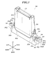
- the inkjet printhead 200 includes a cover 201 and an ink ejection section 202.
- the cover 201 is a protector to contain a circuit board to control the ink ejection from the nozzles N and a connector CN connected to the circuit board.
- the upper surface of the cover 201 has an insertion opening 201b through which the connector CN is to be inserted.
- the cover 201 is provided with locking pieces 201a at the lower ends on both sides (right and left) of the cover 201.
- the ink ejection section 202 includes a casing 202a on which the cover 201 is mounted.
- the casing 202a is made of, for example, aluminum and is formed through die casting.
- the casing 202a is hollow, substantially in a box shape with its bottom open, and elongated in the left-right direction.
- the casing 202a contains a head chip to eject ink from the nozzles N, a manifold to introduce ink to channels of the head chip, and a wiring substrate connected to the head chip, for example.
- a cap member 202d (see FIG. 5 ) is provided so as to cover the open bottom of the casing 202a.
- the cap member 202d is substantially rectangular in shape elongated in the left-right direction.
- the cap member 202d has an opening 202da for nozzles roughly in its center to expose the nozzle plate 202c at the bottom.
- the nozzle plate 202c has a rectangular nozzle-formed area NA to face the opening 202da for nozzles.
- the nozzle-formed area NA includes one or more nozzle rows each including multiple nozzles N arranged in the left-right direction.
- the nozzle plate 202c serves as a nozzle-formed member.
- the casing 202a serves as a support to support the nozzle-formed member.
- the upper surface of the casing 202a has an opening, and a pair of locking holes 202b are provided on both sides (right and left) of the opening.
- the opening of the casing 202a is covered with the cover 201, and a pair of locking pieces 201a of the cover 201 are locked together with the locking holes 202b of the casing 202a, respectively, thereby attaching the cover 201 to the casing 202a.
- Upright ink ports 202e are disposed on the upper surface of the casing 202a on both sides (right and left) of the opening of the casing 202a.
- the ink ports 202e are connected to an ink supply section (not shown) to let ink from the ink supply section flow to the manifold.
- Projections 202f and 202g are provided at right and left ends of the casing 202a, each of the projections 202f and 202g projecting laterally and formed integrally with the casing 202a.
- Each of the projections 202f and 202g has a predetermined thickness ranging from the almost center part to the upper part of the casing 202a in the height direction.
- At least the upper and lower surfaces of each of the projections 202f and 202g are flat surfaces. The lower surfaces of the projections 202f and 202g are in contact with the upper surface of the frame 21 when the inkjet printhead 200 is mounted on the frame 21.
- the heat generated by driving of the inkjet printhead 200 can be released from the casing 202a to the frame 21 through the projections 202f and 202g.
- At least one of the projections 202f and 202g having flat upper and lower surfaces can achieve excellent heat release effects.
- the projection 202f to which a later-described positioning member 203 is to be attached, has flat upper and lower surfaces, it achieves better heat release effects and is preferable. This reduces unevenness in temperature.
- the projections 202f and 202g are formed integrally with the casing 202a in this embodiment, the projections 202f and 202g are excellent in strength and heat conductivity, achieving excellent heat release effects.
- the projection 202f is disposed at the right end of the casing 202a and is substantially in a box shape.
- the right side of the projection 202f has a notch having a V shape in a plan view.
- the inner surfaces of the notch constitute a first surface 202fa and a second surface 202fb.
- the first surface 202fa and the second surface 202fb are continuous with each other and form a predetermined angle (e.g., 90°).
- the projection 202f has a plate attachment screw receiving hole 202h, into which a plate attachment screw 204 (described later) is to be screwed, and a mounting screw insertion hole 202i, which is in front of the plate attachment screw receiving hole 202h and into which a mounting screw 205 (described later) is to be inserted (see FIGS. 7A and 8 ).
- the angle of the notch formed in the projection 202f is not limited to 90° but may be set to any other angle appropriately.
- a flat-plate positioning member 203 is provided on the upper surface of the projection 202f.
- the positioning member 203 has substantially the same shape as the projection 202f in a plan view. Specifically, the positioning member 203 has a V-notch at its right edge, and the thickness of the V-notch forms a first contact surface 203a and a second contact surface 203b. In this embodiment, the first contact surface 203a and the second contact surface 203b constitute a touch surface.
- the positioning member 203 has a plate attachment screw insertion hole 203c, into which the plate attachment screw 204 is to be inserted, and a mounting screw insertion hole 203d, which is in front of the plate attachment screw insertion hole 203c and into which the mounting screw 205 is to be inserted (see FIGS.
- the positioning member 203 is laid on the upper surface of the projection 202f, and the plate attachment screw 204 is inserted into the plate attachment screw insertion hole 203c of the positioning member 203 and is screwed into the plate attachment screw receiving hole 202h of the projection 202f.
- the positioning member 203 is thus fixed to the projection 202f.
- the diameter of the plate attachment screw insertion hole 203c is a little larger than that of the shank of the plate attachment screw 204, which creates clearances a1 and a2 as shown in FIG. 7B . This allows selection of the attachment position of the positioning member 203 with respect to the projection 202f within the range of the clearances a1 and a2.
- the positioning member 203 is attached to the upper surface of the projection 202f, allowing easy positioning of the positioning member 203. Further, when the positioning member 203 is no longer necessary after the inkjet printhead 200 is fixed to the frame 21, the positioning member 203 can easily be removed.
- the projection 202g is disposed at the left end part of the casing 202a.
- the back part of the projection 202g is cut out, and the projection 202g is in an L shape in a plan view.
- the back surface of the cutout part of the projection 202g forms a contact surface 202ga.
- the projection 202g has a mounting screw insertion hole 202i, into which the mounting screw 205 is to be inserted.
- the diameter of the mounting screw insertion holes 202i provided in the right and left projections 202f and 202g is a little larger than that of the shank of the mounting screw 205. This allows the mounting position of the inkjet printhead 200 to the frame 21 to be changed.
- the first surface 202fa and the second surface 202fb of the projection 202f are brought into contact with the positioning shaft 23a of the frame 21, and the contact surface 202ga of the projection 202g is brought into contact with the positioning shaft 23b, thereby positioning the inkjet printhead 200 at a first position.
- the inkjet printhead 200 which has the above-described configuration, is positioned and mounted to the frame 21 at a position different from the first position in the following way.
- the positioning member 203 is placed on the upper surface of the projection 202f of the casing 202a with the cover, and the plate attachment screw 204 is inserted into the plate attachment screw insertion hole 203c of the positioning member 203 and is screwed into the plate attachment screw receiving hole 202h in the projection 202f.
- screwing the plate attachment screw 204 loosely to some extent so that the positioning member 203 is movable within the range of the clearances a1 and a2 makes the positioning of the positioning member 203 (described later) easier.
- the inkjet printhead 200 is placed on the frame 21 in such a way that the lower part of the casing 202a fits in the opening 22 formed in the frame 21 at the mounting position of the inkjet printhead 200.
- the lower surfaces of the projections 202f and 202g are in contact with the upper surface of the frame 21.
- the first surface 202fa and the second surface 202fb of the projection 202f, and the first contact surface 203a and the second contact surface 203b of the positioning member 203 face a positioning shaft 23a of the frame 21; and the contact surface 202ga of the projection 202g faces a positioning shaft 23b of the frame 21.
- the mounting position of the inkjet printhead 200 is fine-tuned with, for example, a microscope, while the positions of the nozzles N are being checked.
- the positioning member 203 is brought into contact with the positioning shaft 23a in such a way that the first contact surface 203a and the second contact surface 203b of the positioning member 203 touch the positioning shaft 23a (or hold the positioning shaft 23a between the first and second contact surfaces 203a and 203b).
- the plate attachment screw 204 is tightened to completely fix the positioning member 203 to the projection 202f to prevent the positioning member 203 from moving.
- the positioning shaft 23a is held between the first contact surface 203a and the second contact surface 203b of the positioning member 203, and thereby the position of one end part of the inkjet printhead 200 is determined. Further, the contact surface 202ga of the projection 202g is brought into contact with the positioning shaft 23b, preventing the rotation of the inkjet printhead 200 about the vertical axis.
- the inkjet printhead 200 is thus located on the frame 21 at a position different from the first position mentioned above. This eliminates the need for another fine adjustment of the inkjet printhead 200 and achieves easy positioning, leading to reduction in cost for the mounting.
- the positioning member 203 provided on only one of the projections 202f and 202g is enough. This achieves downsizing of the inkjet printhead 200 with reduced number of parts, and achieves easy adjustment of the attachment position of the positioning member 203.
- the positioning member 203 is not necessary.
- the mounting screws 205 are inserted into the mounting screw insertion holes 202i in the projections 202f and 202g while the inkjet printhead 200 is fixed with a jig, such as a clamp, so as not to shift in position, and the mounting screws 205 are screwed into the mounting screw receiving holes 24a and 24b in the frame 21.
- the inkjet printhead 200 is thus completely fixed to the frame 21.
- the head parts of the mounting screws 205 press the projections 202f and 202g and give turning force about the vertical axis to the inkjet printhead 200 through the projections 202f and 202g.
- the inkjet printhead 200 does not turn because of the pressing force of the first contact surface 203a and the second contact surface 203b of the positioning member 203 to the positioning shaft 23a and the pressing force of the contact surface 202ga of the projection 202g to the positioning shaft 23b.
- the screwing process thus does not cause the inkjet printhead 200 to shift in position.
- a pair of projections 202f and 202g are formed at both ends of the casing 202a in the longitudinal direction integrally with the casing 202a.
- One of the projections 202f and 202g includes the first surface 202fa and the second surface 202fb, and the other of the projections 202f and 202g (projection 202g) includes the contact surface 202ga.
- Each of the first surface 202fa, the second surface 202fb, and the contact surface 202ga includes a touch part to allow the inkjet printhead 200 to be located at a first position on the inkjet printhead mounting surface of the frame 21 on which the inkjet printhead 200 is to be mounted.
- the positioning member 203 having a touch surface is attached to at least one of the projections 202f and 202g (projection 202f).
- the positioning member 203 is attached in such a way that (i) the first surface 202fa and the touch surface (first contact surface 203a) of the positioning member 203, (ii) the second surface 202fb and the touch surface (second contact surface 203b) of the positioning member 203, or (iii) the two touch surfaces (first contact surface 203a and second contact surface 203b) of the positioning member 203 allow the inkjet printhead 200 to be positioned at a position different from the first position when the inkjet printhead 200 is at a predetermined mounting position on the frame 21.
- the positioning member 203 includes the first contact surface 203a and the second contact surface 203b, and the first contact surface 203a and second contact surface 203b form a V shape. This enables easy adjustment of the attachment position of the positioning member 203.
- the positioning member 203 is attached to the upper surface of the projection 202f, enabling easy adjustment of the position of the positioning member 203. Further, the positioning member 203 can be removed easily when the positioning member 203 is no longer necessary after the inkjet printhead is fixed to the frame.
- At least the projection 202f, to which the positioning member 203 is to be attached is formed in such a way that the bottom surface of the projection 202f is in contact with the frame 21 when the inkjet printhead 200 is positioned on the frame 21. This configuration efficiently releases the heat generated by driving of the inkjet printhead to the frame.
- the projection 202f to which the positioning member 203 is to be attached, has the same shape as the positioning member 203 in a plan view. Accordingly, if the inkjet printhead has high accuracy and can be accurately mounted on the frame, there is an option not to use the positioning member 203. This can reduce the number of parts, leading to reduction in cost for the mounting process.
- the positioning member 203 has the plate attachment screw insertion hole 203c into which the plate attachment screw 204 is to be inserted; and the projection 202f, to which the positioning member 203 is to be attached, has the plate attachment screw receiving hole 202h into which the plate attachment screw 204 is to be screwed.
- the plate attachment screw 204 is inserted into the plate attachment screw insertion hole 203c of the positioning member 203 and is screwed into the plate attachment screw receiving hole 202h of the projection 202f, so that the positioning member 203 is attached to the projection 202f.
- the plate attachment screw insertion hole 203c has a diameter such that the attachment position of the positioning member 203 with respect to the projection 202f is selectable within a predetermined range. Such a configuration enables easy attachment of the positioning member 203 and easy adjustment of the attachment position of the positioning member 203.
- the present invention is not limited to the embodiment described above, which is just an example of an inkjet recording apparatus according to the present invention.
- the detailed configuration and operation of each function section of the inkjet recording apparatus may be modified as appropriate.
- the positioning member 203 touches the positioning shaft 23a in such a way that the first contact surface 203a and the second contact surface 203b of the positioning member 203 are brought into contact with the positioning shaft 23a.
- the positioning member 203 may touch the positioning shaft 23a in such a way that the first contact surface 203a of the positioning member 203 and the second surface 202fb of the projection 202f are brought into contact with the positioning shaft 23a, or in such a way that the second contact surface 203b of the positioning member 203 and the first surface 202fa of the projection 202f are brought into contact with the positioning shaft 23a.
- the positioning member 203 is provided on one of the projections 202f and 202g (i.e., projection 202f).
- the positioning member 203 may also be provided on the other of the projections 202f and 202g (i.e., projection 202g) so that the positioning member on the projection 202g constitutes a contact surface. This enables easy adjustment of the inkjet printhead 200 in the front-back direction.
- the projection 202f to which the positioning member 203 is to be attached, has the same shape as the positioning member 203 in a plan view.
- the shapes of the projection 202f and the positioning member 203 may be different from each other.
- the projection 202f does not necessarily have to include the first surface 202fa and the second surface 202fb as long as the positioning member 203 has the first contact surface 203a and the second contact surface 203b.
- the positioning member 203 is attached to the upper surface of the projection 202f, but may be attached to a part of the projection 202f other than the upper surface.
- each of the projections 202f and 202g has a flat bottom surface, and the bottom surfaces of the projections 202f and 202g are in contact with the frame 21 when the inkjet printhead 200 is mounted on the frame 21.
- the bottom surfaces are not necessarily have to be flat.
- legs projecting downward may be provided on the bottom surface of each of the projections 202f and 202g, and the legs may come into contact with the frame 21.
- the positioning member 203 is fixed to the projection 202f with a screw, but may be fixed with other means, such as gluing or welding.
- the attachment position of the positioning member 203 is adjusted after the inkjet printhead 200 is mounted on the frame 21.
- the inkjet printhead 200 may be mounted on a jig having the same configuration as the frame 21 so that the attachment position of the positioning member 203 may be adjusted, and after that the inkjet printhead 200 may be mounted to the frame 21.
- the inkjet printhead 200 is placed on and mounted to the upper surface of the thin-plate frame 21 as described above.
- a frame 321 shown in FIG. 10 may be used instead of the frame 21.
- the frame 321 has recesses 321a, in which the lower parts of the inkjet printheads 200 fit, to determine the positions of the inkjet printheads 200.
- the frame 321 is a thin plate extending in the left-right direction and having a thickness larger than that of the frame 21.
- the upper surface of the frame 321 has recesses 321a in which the lower parts of the inkjet printheads 200 fit.
- Each of the recesses 321a has a bottom surface 321b to support, from the bottom, an inkjet printhead 200 fitting in the recess 321a.
- the bottom surface 321b has an opening 322 in its center part so that the nozzles N of a mounted inkjet printhead 200 face downward through the opening 322.
- the depth of the recesses 321a may be determined to any distance.
- the inner wall of the recess 321a has positioning bosses 323a and 323b at the right end of the inner wall and near the left end on the back side of the inner wall, respectively.
- Each of the positioning bosses 323a and 323b has an ellipsoidal shape projecting inward and extends vertically.
- the positioning bosses 323a and 323b have the same function as the positioning shafts 23a and 23b of the frame 21 described above and determine the mounting position of the inkjet printhead 200.
- the shape of the positioning bosses 323a and 323b is not limited to the shape described above.
- Mounting screw receiving holes 324a and 324b into which mounting screws 205 are to be screwed are provided near the positioning bosses 323a and 323b, respectively.
- the frame 321 of this embodiment has the recesses 321a in which the inkjet printheads 200 fit and thereby enables more accurate and easy positioning of the inkjet printheads on the frame 321.
- the positioning member 203 is attached to the projection 202f as described above, and then the inkjet printhead 200 is placed on the frame 321 in such a way that the casing 202a of the inkjet printhead 200 fits in the recess 321a.
- the mounting position of the inkjet printhead 200 is then fine-tuned as described above.
- the positioning member 203 is made to touch the positioning boss 323a in such a way that the first contact surface 203a and the second contact surface 203b of the positioning member 203 are brought into contact with the lateral surface of the positioning boss 323a.
- the plate attachment screw 204 is then tightened to completely fix the positioning member 203 to the projection 202f.
- the mounting screws 205 are then inserted into the mounting screw insertion holes 202i of the projections 202f and 202g and are screwed into the mounting screw receiving holes 324a and 324b of the frame 321, respectively, to fix the inkjet printhead 200 to the frame 321.
- the projection 202f and the positioning member 203 each have a V-shaped notch.
- the projection 202f and the positioning member 203 may have any shape as long as the two surfaces (i.e., the first surface 202fa and the second surface 202fb) can come into contact with the positioning shaft 23a.
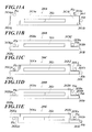
- inkjet printheads 200A to 200E shown in FIGS. 11A to 11E may be applied.
- the inkjet printhead 200A includes a casing 202Aa having projections 202Af and 202Ag that are projecting laterally and are formed integrally with the casing 202Aa at the right and left ends of the casing 202Aa.
- the projections 202Af and 202Ag are substantially in the shape of a box similarly to the projections 202f and 202g of the inkjet printhead 200 of the above-mentioned embodiment, but do not have a notch.
- the projection 202Af is provided with a positioning member 203A attached to the upper surface of the projection 202Af.
- the positioning member 203A has substantially the same shape (i.e., rectangular shape) as the projection 202Af in a plan view, and is a thin plate having a predetermined thickness.
- the back surface of the positioning member 203A having such a configuration, serves as a first contact surface 203Aa, and the right end surface of the positioning member 203A serves as a second contact surface 203Ab.
- the back surface and the right end surface of the projection 202Af serve as a first surface and a second surface, respectively, in the same manner.
- a frame, on which the inkjet printhead 200A is to be mounted, is provided with three positioning shafts P1a, P1b, and P1c disposed upright on the upper surface of the frame, the positioning shafts P1a, P1b, and P1c corresponding to the mounting position of the inkjet printhead 200A.
- the positioning shaft P1a is disposed at a position to face the back surface of the projection 202Af
- the positioning shaft P1b is disposed at a position to face the right end surface of the projection 202Af
- the positioning shaft P1c is disposed at a position to face the back surface of the projection 202Ag.
- the first contact surface 203Aa of the positioning member 203A is brought into contact with the positioning shaft P1a and the second contact surface 203Ab of the positioning member 203A is brought into contact with the positioning shaft P1b, thereby determining the position of the positioning member 203A and allowing the projection 202Af to be held.
- the contact surface 202Aga formed on the back surface of the projection 202Ag is brought into contact with the positioning shaft P1c, thereby allowing the projection 202Ag to be held.
- the inkjet printhead 200A having the configuration described above, thus can be positioned on the frame.
- the inkjet printhead 200B includes a casing 202Ba having projections 202Bf and 202Bg that are projecting laterally and are formed integrally with the casing 202Ba at the right and left ends of the casing 202Ba.
- the projections 202Bf and 202Bg are substantially in the shape of a box similarly to the projections 202f and 202g of the inkjet printhead 200 of the above-mentioned embodiment, but each have a cutout at the back part to have an L shape in a plan view.
- the projection 202Bf is provided with a positioning member 203B attached to the upper surface of the projection 202Bf.
- the positioning member 203B has substantially the same shape (i.e., L shape due to the cutout) as the projection 202Bf in a plan view, and is a thin plate having a predetermined thickness.
- the surfaces of the cutout part in the projection 202Bf serve as a first surface and a second surface, respectively, in the same manner.
- a frame, on which the inkjet printhead 200B is to be mounted, is provided with two positioning shafts P2a and P2b disposed upright on the upper surface of the frame, the positioning shafts P2a and P2b corresponding to the mounting position of the inkjet printhead 200B.
- the positioning shaft P2a is disposed at a position to face the lateral and back surfaces of the cutout part of the projection 202Bf
- the positioning shaft P2b is disposed at a position to face the back surface of the cutout part of the projection 202Bg as a contact surface 202Bga.
- the first and second contact surfaces 203Ba and 203Bb are brought into contact with the positioning shaft P2a to hold the positioning shaft P2a between the first and second contact surfaces 203Ba and 203Bb, thereby determining the position of the positioning member 203B and allowing the projection 202Bf to be held. Further, the contact surface 202Bga of the projection 202Bg is brought into contact with the positioning shaft P2b, thereby allowing the projection 202Bg to be held.
- the inkjet printhead 200B having the configuration described above, thus can be positioned on the frame.
- the inkjet printhead 200C includes a casing 202Ca having projections 202Cf and 202Cg that are projecting laterally and are formed integrally with the casing 202Ca at the right and left ends of the casing 202Ca.
- the inkjet printhead 200C has the same shape as the inkjet printhead 200B described above but is different from the inkjet printhead 200B in that a first contact surface 203Ca of a positioning member 203C is the back surface of the cutout part and in that a second contact surface 203Cb is the right end surface of the positioning member 203C.
- a frame, on which the inkjet printhead 200C is to be mounted, is provided with three positioning shafts P3a, P3b, and P3c disposed upright on the upper surface of the frame, the positioning shafts P3a, P3b, and P3c corresponding to the mounting position of the inkjet printhead 200C.
- the positioning shaft P3a is disposed at a position to face the back surface of the cutout part of the projection 202Cf
- the positioning shaft P3b is disposed at a position to face the right end surface of the projection 202Cf
- the positioning shaft P3c is disposed at a position to face the back surface of the cutout part of the projection 202Cg as a contact surface 202Cga.
- the first contact surface 203Ca of the positioning member 203C is brought into contact with the positioning shaft P3a and the second contact surface 203Cb of the positioning member 203C is brought into contact with the positioning shaft P3b, thereby determining the position of the positioning member 203C and allowing the projection 202Cf to be held.
- the contact surface 202Cga formed on the back surface of the projection 202Cg is brought into contact with the positioning shaft P3c, thereby allowing the projection 202Cg to be held.
- the inkjet printhead 200C having the configuration described above, thus can be positioned on the frame.
- the inkjet printhead 200D includes a casing 202Da having projections 202Df and 202Dg that are projecting laterally and are formed integrally with the casing 202Da at the right and left ends of the casing 202Da.
- the inkjet printhead 200D has the same shape as the inkjet printhead 200B described above.
- a frame, on which the inkjet printhead 200D is to be mounted, is provided with three positioning shafts P4a, P4b, and P4c disposed upright on the upper surface of the frame, the positioning shafts P4a, P4b, and P4c corresponding to the mounting position of the inkjet printhead 200D.
- the positioning shaft P4a is disposed at a position to face the lateral surface of the cutout part of the projection 202Df
- the positioning shaft P4b is disposed at a position to face the back surface of the cutout part of the projection 202Df
- the positioning shaft P4c is disposed at a position to face the back surface of the cutout part of the projection 202Dg as a contact surface 202Dga.
- the first contact surface 203Da of the positioning member 203D is brought into contact with the positioning shaft P4a and the second contact surface 203Db of the positioning member 203D is brought into contact with the positioning shaft P4b, thereby determining the position of the positioning member 203D and allowing the projection 202Df to be held.
- the contact surface 202Dga formed on the back surface of the projection 202Dg is brought into contact with the positioning shaft P4c, thereby allowing the projection 202Dg to be held.
- the inkjet printhead 200D having the configuration described above, thus can be positioned on the frame.
- the inkjet printhead 200E includes a casing 202Ea having projections 202Ef and 202Eg that are projecting laterally and are formed integrally with the casing 202Ea at the right and left ends of the casing 202Ea.
- the projections 202Ef and 202Eg are substantially in the shape of a box similarly to the projections 202f and 202g of the inkjet printhead 200 of the above-mentioned embodiment, but the back part of the projection 202Ef and the front part of the projection 202Eg are cut out. That is, the projections 202Ef and 202Eg have an L shape in a plan view.
- the projection 202Ef is provided with a positioning member 203E attached to the upper surface of the projection 202Ef.
- the positioning member 203E has substantially the same shape (i.e., L shape due to the cutout) as the projection 202Ef in a plan view, and is a thin plate having a predetermined thickness.
- the back surface of the cutout part of the positioning member 203E having such a configuration, serve as a first contact surface 203Ea, and the right end surface of the positioning member 203E serves as a second contact surface 203Eb.
- back surface of the cutout part of the projection 202Ef and the right end surface of the projection 202Ef serve as a first surface and a second surface, respectively, in the same manner.
- a frame, on which the inkjet printhead 200E is to be mounted, is provided with three positioning shafts P5a, P5b, and P5c disposed upright on the upper surface of the frame, the positioning shafts P5a, P5b, and P5c corresponding to the mounting position of the inkjet printhead 200E.
- the positioning shaft P5a is disposed at a position to face the back surface of the cutout part of the projection 202Ef
- the positioning shaft P5b is disposed at a position to face the right end surface of the projection 202Ef
- the positioning shaft P5c is disposed at a position to face the front surface of the cutout part of the projection 202Eg as a contact surface 202Ega.
- the first contact surface 203Ea of the positioning member 203E is brought into contact with the positioning shaft P5a and the second contact surface 203Eb of the positioning member 203E is brought into contact with the positioning shaft P5b, thereby determining the position of the positioning member 203E and allowing the projection 202Ef to be held.
- the contact surface 202Ega formed on the front surface of the projection 202Eg is brought into contact with the positioning shaft P5c, thereby allowing the projection 202Eg to be held.
- the inkjet printhead 200E having the configuration described above, thus can be positioned on the frame.
Landscapes
- Engineering & Computer Science (AREA)
- Quality & Reliability (AREA)
- Ink Jet (AREA)
- Particle Formation And Scattering Control In Inkjet Printers (AREA)
Abstract
Description
- The present invention relates to an inkjet printhead, an inkjet recording apparatus, and a method for adjusting position of an inkjet printhead.
- A typical inkjet recording apparatus includes inkjet printheads each including a nozzle-formed member having a plurality of nozzles arranged thereon in a row. The inkjet printheads are mounted and held on a frame, and the nozzles eject ink onto a recording medium to form an image on the recording medium.
- In order to improve the accuracy of mounting of such inkjet printheads to a frame, one end part of each support to support a nozzle-formed member is notched to have two contact surfaces. A pair of positioning shafts are disposed upright on the inkjet printhead mounting surface of the frame, and one of the positioning shafts is held between the two contact surfaces to determine the rotation axis of the inkjet printhead, and one contact surface formed on the other end part of the support is brought into contact with the other of the positioning shafts to prevent rotation of the inkjet printhead. The inkjet printhead is thus positioned and is fixed with, for example, screws in this state to be mounted to the frame (see, for example, Japanese Unexamined Patent Application Publication No.
2008-296518 - An inkjet printhead is assembled with many parts, and each part has a shaping error. Cumulative shaping errors and assembling errors result in variation in accuracy of products. The inkjet printhead disclosed in Japanese Unexamined Patent Application Publication No.
2008-296518 - An object of the present invention is to provide an inkjet printhead, an inkjet recording apparatus, and a method for adjusting position of an inkjet printhead that require less mounting cost.
- To achieve the above-mentioned object, an inkjet printhead reflecting one aspect of the present invention includes an inkjet printhead comprising a support to support a nozzle-formed member including a plurality of nozzles to eject ink, wherein the support includes a pair of projections at both ends of the support in a longitudinal direction, the projections being formed integrally with the support; one of the projections includes a first surface and a second surface, and the other of the projections includes a contact surface; each of the first surface, the second surface, and the contact surface includes a touch part to allow the inkjet printhead to be positioned at a first position on an inkjet printhead mounting surface of a frame on which the inkjet printhead is to be mounted; and a positioning member including a touch surface is attached to one of the projections in such a way that (i) the first surface and the touch surface of the positioning member or (ii) the second surface and the touch surface of the positioning member or (iii) two touch surfaces of the positioning member allow the inkjet printhead to be positioned at a position different from the first position when the inkjet printhead is at a predetermined mounting position on the frame.
- Preferably, the positioning member includes a first touch surface and a second touch surface; and the first touch surface and the second touch surface form a V shape.
- Preferably, the positioning member is attached to an upper surface of the projection.
- Preferably, a bottom surface of at least the projection to which the positioning member is attached of the projections is in contact with the frame when the inkjet printhead is positioned on the frame.
- Preferably, the projection to which the positioning member is to be attached has the same shape as the positioning member in a plan view.
- Preferably, the positioning member has a screw insertion hole for insertion of a screw; the projection to which the positioning member is to be attached has a screw receiving hole into which the screw is to be screwed; the positioning member is attached to the projection in such a way that the screw is inserted through the screw insertion hole of the positioning member and is screwed into the screw receiving hole of the projection; and the screw insertion hole has a diameter such that an attachment position of the positioning member with respect to the projection is selectable within a predetermined range.
- An inkjet recording apparatus reflecting another aspect of the present invention includes the above-described inkjet printhead; and the frame including a pair of positioning shafts disposed upright on the inkjet printhead mounting surface on which the inkjet printhead is to be mounted, wherein (i) the first surface and the touch surface of the positioning member are brought into contact with one of the positioning shafts or (ii) the second surface and the touch surface of the positioning member are brought into contact with one of the positioning shafts or (iii) the two touch surfaces of the positioning member hold one of the positioning shafts between the two touch surfaces, for the inkjet printhead to be supported; and the contact surface is brought into contact with the other of the positioning shafts to prevent rotation of the inkjet printhead, so that the inkjet printhead is positioned and fixed at the predetermined mounting position on the frame.
- Preferably, the frame has a recess in which the inkjet printhead fits.
- A method for adjusting a position of an inkjet printhead reflecting another aspect of the present invention uses an inkjet printhead including a support to support a nozzle-formed member including a plurality of nozzles to eject ink, wherein the support includes a pair of projections at both ends of the support in a longitudinal direction, the projections being formed integrally with the support, one of the projections includes a first surface and a second surface, and the other of the projections includes a contact surface, each of the first surface, the second surface, and the contact surface includes a touch part to allow the inkjet printhead to be positioned at a first position on an inkjet printhead mounting surface of a frame on which the inkjet printhead is to be mounted, the method comprising. The method for adjusting the position of the inkjet printhead includes placing the inkjet printhead at a predetermined mounting position on the inkjet printhead mounting surface; and positioning the inkjet printhead with (i) the first surface and a touch surface of a positioning member attached to one of the projections or (ii) the second surface and the touch surface of the positioning member or (iii) two touch surfaces of the positioning member when the inkjet printhead is at the predetermined mounting position different from the first position.
- The present invention can reduce cost for a mounting process.
- The above and other objects, advantages and features of the present invention will become more fully understood from the detailed description given hereinbelow and the appended drawings which are given by way of illustration only, and thus are not intended as a definition of the limits of the present invention, and wherein:
-
FIG. 1 is a perspective view showing the schematic configuration of an inkjet recording apparatus; -
FIG. 2 is a perspective view showing the schematic configuration of a recording printhead unit; -
FIG. 3 is a perspective view showing the external appearance of an inkjet printhead; -
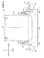
FIG. 4 is a front view of an inkjet printhead; -
FIG. 5 is a bottom view of an inkjet printhead; -
FIG. 6 is a plan view of an inkjet printhead; -
FIG. 7A is an enlarged cross-sectional view along the line A-A ofFIG. 4 ; -
FIG. 7B is an enlarged cross-sectional view of the part of a plate attachment screw inFIG. 7A ; -
FIG. 8 describes attachment of a positioning member; -
FIG. 9 describes mounting of an inkjet printhead to a frame; -
FIG. 10 is a perspective view of another example of a frame; -
FIG. 11A is a schematic bottom view of another example of an inkjet printhead; -
FIG. 11B is a schematic bottom view of another example of an inkjet printhead; -
FIG. 11C is a schematic bottom view of another example of an inkjet printhead; -
FIG. 11D is a schematic bottom view of another example of an inkjet printhead; and -
FIG. 11E is a schematic bottom view of another example of an inkjet printhead. - An inkjet recording apparatus according to an embodiment of the present invention will now be described with reference to the drawings. The scope of the invention, however, is not limited to the examples shown in the drawings. In the following description, the same reference numbers and alphabets are assigned to the components having the same function and configuration, and redundant explanations are omitted.
- As shown in
FIG. 1 , theinkjet recording apparatus 1 includes a platen P to hold a recording medium S. At the front and back of the platen P, conveyance rollers R1 and R2 to convey a recording medium S are disposed. When the conveyance rollers R1 and R2 are driven, a recording medium S is conveyed from the back to front while the recording medium S is supported by the platen P. - In the following description, the conveyance direction in which a recording medium S is conveyed is sometimes referred to as "Y direction" or "front-back direction", and the direction perpendicular to the conveyance direction is sometimes referred to as "X direction" or "left-right direction". The X and Y directions are the directions on the horizontal plane. The direction perpendicular to the X and Y directions is sometimes referred to as a vertical direction.
- Four
recording printhead units 2 are arranged over the platen P from the upstream to downstream in the Y direction. Therecording printhead units 2 each extend in the X direction. The fourrecording printhead units 2 eject cyan, magenta, yellow and black inks (recording material) onto a recording medium S to record an image and text on the recording medium S. The number and order of arrangement of therecording printhead units 2 may be determined arbitrarily. The recording material is not limited to ink but may be, for example, conductive paste. - As shown in
FIG. 2 , each of therecording printhead units 2 has a thin-plate frame 21 extending in the left-right direction. Theframe 21 is rectangular in shape. A plurality ofinkjet printheads 200 are arranged on theframe 21 in a staggered manner in the left-right direction.FIG. 2 shows only oneinkjet printhead 200 on theframe 21 to simplify the explanation, but actually fourinkjet printheads 200 are provided on theframe 21. In this embodiment, therecording printhead units 2, which cover the full width of a conveyed recording medium S, can form an image all over the surface of the recording medium S merely by conveying the recording medium S (i.e., without moving the recording printhead units 2). The number of theinkjet printheads 200 disposed on theframe 21 is not limited to four but may be one or may be other numbers. Therecording printhead units 2 may eject recording material onto a recording medium S for image formation while moving back and forth in the direction (i.e., main scanning direction) perpendicular to the conveyance direction (i.e., sub-scanning direction) of a recording medium S. - Each
frame 21 has substantiallyrectangular openings 22 at the positions where theinkjet printheads 200 are to be mounted so that the nozzles N of theinkjet printheads 200 face downward (seeFIG. 5 ). - A pair of
columnar positioning shafts frame 21, i.e., disposed on both sides (right and left) of each opening 22 on the mounting surface of theinkjet printhead 200. Thepositioning shafts inkjet printhead 200 when theinkjet printhead 200 is mounted. Thepositioning shafts first contact surface 203a and asecond contact surface 203b of a positioning member 203 (seeFIG. 3 ) can be in contact with thepositioning shaft - Mounting
screw receiving holes positioning shafts inkjet printhead 200 positioned at a predetermined mounting position can be fixed to theframe 21 with the mounting screws 205. Theinkjet printhead 200 may be fixed to theframe 21 through any other fixing means, such as gluing or welding, instead of the screws. - The configuration of each of the
inkjet printheads 200 mounted on theframe 21 will now described in detail with reference toFIGS. 3 to 7 . - The
inkjet printhead 200 includes acover 201 and anink ejection section 202. - The
cover 201 is a protector to contain a circuit board to control the ink ejection from the nozzles N and a connector CN connected to the circuit board. The upper surface of thecover 201 has aninsertion opening 201b through which the connector CN is to be inserted. Thecover 201 is provided with lockingpieces 201a at the lower ends on both sides (right and left) of thecover 201. - The
ink ejection section 202 includes acasing 202a on which thecover 201 is mounted. - The
casing 202a is made of, for example, aluminum and is formed through die casting. Thecasing 202a is hollow, substantially in a box shape with its bottom open, and elongated in the left-right direction. Thecasing 202a contains a head chip to eject ink from the nozzles N, a manifold to introduce ink to channels of the head chip, and a wiring substrate connected to the head chip, for example. Acap member 202d (seeFIG. 5 ) is provided so as to cover the open bottom of thecasing 202a. - As shown in
FIG. 5 , thecap member 202d is substantially rectangular in shape elongated in the left-right direction. Thecap member 202d has an opening 202da for nozzles roughly in its center to expose thenozzle plate 202c at the bottom. - The
nozzle plate 202c has a rectangular nozzle-formed area NA to face the opening 202da for nozzles. The nozzle-formed area NA includes one or more nozzle rows each including multiple nozzles N arranged in the left-right direction. In this embodiment, thenozzle plate 202c serves as a nozzle-formed member. Thecasing 202a serves as a support to support the nozzle-formed member. - The upper surface of the
casing 202a has an opening, and a pair of lockingholes 202b are provided on both sides (right and left) of the opening. The opening of thecasing 202a is covered with thecover 201, and a pair of lockingpieces 201a of thecover 201 are locked together with the lockingholes 202b of thecasing 202a, respectively, thereby attaching thecover 201 to thecasing 202a. -
Upright ink ports 202e are disposed on the upper surface of thecasing 202a on both sides (right and left) of the opening of thecasing 202a. Theink ports 202e are connected to an ink supply section (not shown) to let ink from the ink supply section flow to the manifold. -
Projections casing 202a, each of theprojections casing 202a. Each of theprojections casing 202a in the height direction. At least the upper and lower surfaces of each of theprojections projections frame 21 when theinkjet printhead 200 is mounted on theframe 21. Accordingly, the heat generated by driving of theinkjet printhead 200 can be released from thecasing 202a to theframe 21 through theprojections projections projection 202f, to which a later-describedpositioning member 203 is to be attached, has flat upper and lower surfaces, it achieves better heat release effects and is preferable. This reduces unevenness in temperature. Further, since theprojections casing 202a in this embodiment, theprojections - The
projection 202f is disposed at the right end of thecasing 202a and is substantially in a box shape. The right side of theprojection 202f has a notch having a V shape in a plan view. The inner surfaces of the notch constitute a first surface 202fa and a second surface 202fb. The first surface 202fa and the second surface 202fb are continuous with each other and form a predetermined angle (e.g., 90°). Theprojection 202f has a plate attachmentscrew receiving hole 202h, into which a plate attachment screw 204 (described later) is to be screwed, and a mountingscrew insertion hole 202i, which is in front of the plate attachmentscrew receiving hole 202h and into which a mounting screw 205 (described later) is to be inserted (seeFIGS. 7A and8 ). The angle of the notch formed in theprojection 202f is not limited to 90° but may be set to any other angle appropriately. - A flat-
plate positioning member 203 is provided on the upper surface of theprojection 202f. The positioningmember 203 has substantially the same shape as theprojection 202f in a plan view. Specifically, the positioningmember 203 has a V-notch at its right edge, and the thickness of the V-notch forms afirst contact surface 203a and asecond contact surface 203b. In this embodiment, thefirst contact surface 203a and thesecond contact surface 203b constitute a touch surface. The positioningmember 203 has a plate attachmentscrew insertion hole 203c, into which theplate attachment screw 204 is to be inserted, and a mountingscrew insertion hole 203d, which is in front of the plate attachmentscrew insertion hole 203c and into which the mountingscrew 205 is to be inserted (seeFIGS. 7A and8 ). The positioningmember 203 is laid on the upper surface of theprojection 202f, and theplate attachment screw 204 is inserted into the plate attachmentscrew insertion hole 203c of thepositioning member 203 and is screwed into the plate attachmentscrew receiving hole 202h of theprojection 202f. The positioningmember 203 is thus fixed to theprojection 202f. The diameter of the plate attachmentscrew insertion hole 203c is a little larger than that of the shank of theplate attachment screw 204, which creates clearances a1 and a2 as shown inFIG. 7B . This allows selection of the attachment position of thepositioning member 203 with respect to theprojection 202f within the range of the clearances a1 and a2. In this embodiment, the positioningmember 203 is attached to the upper surface of theprojection 202f, allowing easy positioning of thepositioning member 203. Further, when thepositioning member 203 is no longer necessary after theinkjet printhead 200 is fixed to theframe 21, the positioningmember 203 can easily be removed. - The
projection 202g is disposed at the left end part of thecasing 202a. The back part of theprojection 202g is cut out, and theprojection 202g is in an L shape in a plan view. The back surface of the cutout part of theprojection 202g forms a contact surface 202ga. Theprojection 202g has a mountingscrew insertion hole 202i, into which the mountingscrew 205 is to be inserted. The diameter of the mountingscrew insertion holes 202i provided in the right and leftprojections screw 205. This allows the mounting position of theinkjet printhead 200 to theframe 21 to be changed. - In this embodiment, the first surface 202fa and the second surface 202fb of the
projection 202f are brought into contact with thepositioning shaft 23a of theframe 21, and the contact surface 202ga of theprojection 202g is brought into contact with thepositioning shaft 23b, thereby positioning theinkjet printhead 200 at a first position. - The
inkjet printhead 200, which has the above-described configuration, is positioned and mounted to theframe 21 at a position different from the first position in the following way. - First, as shown in
FIG. 8 , the positioningmember 203 is placed on the upper surface of theprojection 202f of thecasing 202a with the cover, and theplate attachment screw 204 is inserted into the plate attachmentscrew insertion hole 203c of thepositioning member 203 and is screwed into the plate attachmentscrew receiving hole 202h in theprojection 202f. At this time, screwing theplate attachment screw 204 loosely to some extent so that thepositioning member 203 is movable within the range of the clearances a1 and a2 makes the positioning of the positioning member 203 (described later) easier. - Next, as shown in
FIG. 9 , theinkjet printhead 200 is placed on theframe 21 in such a way that the lower part of thecasing 202a fits in theopening 22 formed in theframe 21 at the mounting position of theinkjet printhead 200. At this time, the lower surfaces of theprojections frame 21. In this state, the first surface 202fa and the second surface 202fb of theprojection 202f, and thefirst contact surface 203a and thesecond contact surface 203b of thepositioning member 203 face apositioning shaft 23a of theframe 21; and the contact surface 202ga of theprojection 202g faces apositioning shaft 23b of theframe 21. - The mounting position of the
inkjet printhead 200 is fine-tuned with, for example, a microscope, while the positions of the nozzles N are being checked. After the mounting position is determined in this way, the positioningmember 203 is brought into contact with thepositioning shaft 23a in such a way that thefirst contact surface 203a and thesecond contact surface 203b of thepositioning member 203 touch thepositioning shaft 23a (or hold thepositioning shaft 23a between the first andsecond contact surfaces plate attachment screw 204 is tightened to completely fix thepositioning member 203 to theprojection 202f to prevent thepositioning member 203 from moving. As a result, thepositioning shaft 23a is held between thefirst contact surface 203a and thesecond contact surface 203b of thepositioning member 203, and thereby the position of one end part of theinkjet printhead 200 is determined. Further, the contact surface 202ga of theprojection 202g is brought into contact with thepositioning shaft 23b, preventing the rotation of theinkjet printhead 200 about the vertical axis. Theinkjet printhead 200 is thus located on theframe 21 at a position different from the first position mentioned above. This eliminates the need for another fine adjustment of theinkjet printhead 200 and achieves easy positioning, leading to reduction in cost for the mounting. Further, since two surfaces, i.e., thefirst contact surface 203a and thesecond contact surface 203b of thepositioning member 203, touch thepositioning shaft 23a, the positioningmember 203 provided on only one of theprojections inkjet printhead 200 with reduced number of parts, and achieves easy adjustment of the attachment position of thepositioning member 203. - If the
inkjet printhead 200 has high accuracy and is accurately mounted on theframe 21 with the first surface 202fa and the second surface 202fb of theprojection 202f and the contact surface 202ga of theprojection 202g, the positioningmember 203 is not necessary. - After the
inkjet printhead 200 is positioned, the mountingscrews 205 are inserted into the mountingscrew insertion holes 202i in theprojections inkjet printhead 200 is fixed with a jig, such as a clamp, so as not to shift in position, and the mountingscrews 205 are screwed into the mountingscrew receiving holes frame 21. Theinkjet printhead 200 is thus completely fixed to theframe 21. When the mountingscrews 205 are screwed, the head parts of the mountingscrews 205 press theprojections inkjet printhead 200 through theprojections inkjet printhead 200, however, does not turn because of the pressing force of thefirst contact surface 203a and thesecond contact surface 203b of thepositioning member 203 to thepositioning shaft 23a and the pressing force of the contact surface 202ga of theprojection 202g to thepositioning shaft 23b. The screwing process thus does not cause theinkjet printhead 200 to shift in position. - As described above, according to the embodiment, a pair of
projections casing 202a in the longitudinal direction integrally with thecasing 202a. One of theprojections projection 202f) includes the first surface 202fa and the second surface 202fb, and the other of theprojections projection 202g) includes the contact surface 202ga. Each of the first surface 202fa, the second surface 202fb, and the contact surface 202ga includes a touch part to allow theinkjet printhead 200 to be located at a first position on the inkjet printhead mounting surface of theframe 21 on which theinkjet printhead 200 is to be mounted. The positioningmember 203 having a touch surface is attached to at least one of theprojections projection 202f). The positioningmember 203 is attached in such a way that (i) the first surface 202fa and the touch surface (first contact surface 203a) of thepositioning member 203, (ii) the second surface 202fb and the touch surface (second contact surface 203b) of thepositioning member 203, or (iii) the two touch surfaces (first contact surface 203a andsecond contact surface 203b) of thepositioning member 203 allow theinkjet printhead 200 to be positioned at a position different from the first position when theinkjet printhead 200 is at a predetermined mounting position on theframe 21. Accordingly, even when there is variation in accuracy of inkjet printhead, another fine adjustment of the inkjet printhead is not necessary and positioning can be performed easily, leading to reduction in cost for the mounting process. Further, the heat generated by the driving of the inkjet printhead can be released efficiently. - Further, according to the embodiment, the positioning
member 203 includes thefirst contact surface 203a and thesecond contact surface 203b, and thefirst contact surface 203a andsecond contact surface 203b form a V shape. This enables easy adjustment of the attachment position of thepositioning member 203. - Further, according to the embodiment, the positioning
member 203 is attached to the upper surface of theprojection 202f, enabling easy adjustment of the position of thepositioning member 203. Further, the positioningmember 203 can be removed easily when thepositioning member 203 is no longer necessary after the inkjet printhead is fixed to the frame. - Further, according to the embodiment, at least the
projection 202f, to which thepositioning member 203 is to be attached, is formed in such a way that the bottom surface of theprojection 202f is in contact with theframe 21 when theinkjet printhead 200 is positioned on theframe 21. This configuration efficiently releases the heat generated by driving of the inkjet printhead to the frame. - Further, according to the embodiment, the
projection 202f, to which thepositioning member 203 is to be attached, has the same shape as thepositioning member 203 in a plan view. Accordingly, if the inkjet printhead has high accuracy and can be accurately mounted on the frame, there is an option not to use thepositioning member 203. This can reduce the number of parts, leading to reduction in cost for the mounting process. - Further, according to the embodiment, the positioning
member 203 has the plate attachmentscrew insertion hole 203c into which theplate attachment screw 204 is to be inserted; and theprojection 202f, to which thepositioning member 203 is to be attached, has the plate attachmentscrew receiving hole 202h into which theplate attachment screw 204 is to be screwed. Theplate attachment screw 204 is inserted into the plate attachmentscrew insertion hole 203c of thepositioning member 203 and is screwed into the plate attachmentscrew receiving hole 202h of theprojection 202f, so that thepositioning member 203 is attached to theprojection 202f. The plate attachmentscrew insertion hole 203c has a diameter such that the attachment position of thepositioning member 203 with respect to theprojection 202f is selectable within a predetermined range. Such a configuration enables easy attachment of thepositioning member 203 and easy adjustment of the attachment position of thepositioning member 203. - The present invention is not limited to the embodiment described above, which is just an example of an inkjet recording apparatus according to the present invention. The detailed configuration and operation of each function section of the inkjet recording apparatus may be modified as appropriate.
- In the embodiment, the positioning
member 203 touches thepositioning shaft 23a in such a way that thefirst contact surface 203a and thesecond contact surface 203b of thepositioning member 203 are brought into contact with thepositioning shaft 23a. Alternatively, the positioningmember 203 may touch thepositioning shaft 23a in such a way that thefirst contact surface 203a of thepositioning member 203 and the second surface 202fb of theprojection 202f are brought into contact with thepositioning shaft 23a, or in such a way that thesecond contact surface 203b of thepositioning member 203 and the first surface 202fa of theprojection 202f are brought into contact with thepositioning shaft 23a. - In the embodiment, the positioning
member 203 is provided on one of theprojections projection 202f). Alternatively, the positioningmember 203 may also be provided on the other of theprojections projection 202g) so that the positioning member on theprojection 202g constitutes a contact surface. This enables easy adjustment of theinkjet printhead 200 in the front-back direction. - In the embodiment, the
projection 202f, to which thepositioning member 203 is to be attached, has the same shape as thepositioning member 203 in a plan view. Alternatively, the shapes of theprojection 202f and thepositioning member 203 may be different from each other. Further, theprojection 202f does not necessarily have to include the first surface 202fa and the second surface 202fb as long as thepositioning member 203 has thefirst contact surface 203a and thesecond contact surface 203b. - In the embodiment, the positioning
member 203 is attached to the upper surface of theprojection 202f, but may be attached to a part of theprojection 202f other than the upper surface. - In the embodiment, each of the
projections projections frame 21 when theinkjet printhead 200 is mounted on theframe 21. The bottom surfaces, however, are not necessarily have to be flat. For example, legs projecting downward may be provided on the bottom surface of each of theprojections frame 21. - In the embodiment, the positioning
member 203 is fixed to theprojection 202f with a screw, but may be fixed with other means, such as gluing or welding. - In the embodiment, the attachment position of the
positioning member 203 is adjusted after theinkjet printhead 200 is mounted on theframe 21. Alternatively, for example, theinkjet printhead 200 may be mounted on a jig having the same configuration as theframe 21 so that the attachment position of thepositioning member 203 may be adjusted, and after that theinkjet printhead 200 may be mounted to theframe 21. - In the embodiment, the
inkjet printhead 200 is placed on and mounted to the upper surface of the thin-plate frame 21 as described above. Aframe 321 shown inFIG. 10 may be used instead of theframe 21. Theframe 321 hasrecesses 321a, in which the lower parts of theinkjet printheads 200 fit, to determine the positions of theinkjet printheads 200. - More specifically, the
frame 321 is a thin plate extending in the left-right direction and having a thickness larger than that of theframe 21. The upper surface of theframe 321 hasrecesses 321a in which the lower parts of theinkjet printheads 200 fit. Each of therecesses 321a has abottom surface 321b to support, from the bottom, aninkjet printhead 200 fitting in therecess 321a. Thebottom surface 321b has anopening 322 in its center part so that the nozzles N of a mountedinkjet printhead 200 face downward through theopening 322. The depth of therecesses 321a may be determined to any distance. The inner wall of therecess 321a haspositioning bosses positioning bosses positioning bosses positioning shafts frame 21 described above and determine the mounting position of theinkjet printhead 200. Similarly to thepositioning shafts positioning bosses - Mounting
screw receiving holes screws 205 are to be screwed are provided near thepositioning bosses - The
frame 321 of this embodiment has therecesses 321a in which theinkjet printheads 200 fit and thereby enables more accurate and easy positioning of the inkjet printheads on theframe 321. - In the case in which an
inkjet printhead 200 is mounted on theframe 321 having the configuration as described above, the positioningmember 203 is attached to theprojection 202f as described above, and then theinkjet printhead 200 is placed on theframe 321 in such a way that thecasing 202a of theinkjet printhead 200 fits in therecess 321a. The mounting position of theinkjet printhead 200 is then fine-tuned as described above. After that thepositioning member 203 is made to touch thepositioning boss 323a in such a way that thefirst contact surface 203a and thesecond contact surface 203b of thepositioning member 203 are brought into contact with the lateral surface of thepositioning boss 323a. Theplate attachment screw 204 is then tightened to completely fix thepositioning member 203 to theprojection 202f. The mountingscrews 205 are then inserted into the mountingscrew insertion holes 202i of theprojections screw receiving holes frame 321, respectively, to fix theinkjet printhead 200 to theframe 321. - In the embodiment, the
projection 202f and thepositioning member 203 each have a V-shaped notch. Theprojection 202f and thepositioning member 203, however, may have any shape as long as the two surfaces (i.e., the first surface 202fa and the second surface 202fb) can come into contact with thepositioning shaft 23a. For example,inkjet printheads 200A to 200E shown inFIGS. 11A to 11E may be applied. - Specifically, with reference to
FIG. 11A , theinkjet printhead 200A includes a casing 202Aa having projections 202Af and 202Ag that are projecting laterally and are formed integrally with the casing 202Aa at the right and left ends of the casing 202Aa. The projections 202Af and 202Ag are substantially in the shape of a box similarly to theprojections inkjet printhead 200 of the above-mentioned embodiment, but do not have a notch. The projection 202Af is provided with apositioning member 203A attached to the upper surface of the projection 202Af. The positioningmember 203A has substantially the same shape (i.e., rectangular shape) as the projection 202Af in a plan view, and is a thin plate having a predetermined thickness. The back surface of thepositioning member 203A, having such a configuration, serves as a first contact surface 203Aa, and the right end surface of thepositioning member 203A serves as a second contact surface 203Ab. Although not shown in the drawing, the back surface and the right end surface of the projection 202Af serve as a first surface and a second surface, respectively, in the same manner. A frame, on which theinkjet printhead 200A is to be mounted, is provided with three positioning shafts P1a, P1b, and P1c disposed upright on the upper surface of the frame, the positioning shafts P1a, P1b, and P1c corresponding to the mounting position of theinkjet printhead 200A. The positioning shaft P1a is disposed at a position to face the back surface of the projection 202Af, the positioning shaft P1b is disposed at a position to face the right end surface of the projection 202Af, and the positioning shaft P1c is disposed at a position to face the back surface of the projection 202Ag. After the mounting position of theinkjet printhead 200A is adjusted, the first contact surface 203Aa of thepositioning member 203A is brought into contact with the positioning shaft P1a and the second contact surface 203Ab of thepositioning member 203A is brought into contact with the positioning shaft P1b, thereby determining the position of thepositioning member 203A and allowing the projection 202Af to be held. Further, the contact surface 202Aga formed on the back surface of the projection 202Ag is brought into contact with the positioning shaft P1c, thereby allowing the projection 202Ag to be held. Theinkjet printhead 200A, having the configuration described above, thus can be positioned on the frame. - With reference to
FIG. 11B , theinkjet printhead 200B includes a casing 202Ba having projections 202Bf and 202Bg that are projecting laterally and are formed integrally with the casing 202Ba at the right and left ends of the casing 202Ba. The projections 202Bf and 202Bg are substantially in the shape of a box similarly to theprojections inkjet printhead 200 of the above-mentioned embodiment, but each have a cutout at the back part to have an L shape in a plan view. The projection 202Bf is provided with apositioning member 203B attached to the upper surface of the projection 202Bf. The positioningmember 203B has substantially the same shape (i.e., L shape due to the cutout) as the projection 202Bf in a plan view, and is a thin plate having a predetermined thickness. The lateral surface and the back surface of the cutout part of thepositioning member 203B, having such a configuration, serve as a first contact surface 203Ba and a second contact surface 203Bb, respectively. Although not shown in the drawing, the surfaces of the cutout part in the projection 202Bf serve as a first surface and a second surface, respectively, in the same manner. A frame, on which theinkjet printhead 200B is to be mounted, is provided with two positioning shafts P2a and P2b disposed upright on the upper surface of the frame, the positioning shafts P2a and P2b corresponding to the mounting position of theinkjet printhead 200B. The positioning shaft P2a is disposed at a position to face the lateral and back surfaces of the cutout part of the projection 202Bf, and the positioning shaft P2b is disposed at a position to face the back surface of the cutout part of the projection 202Bg as a contact surface 202Bga. After the mounting position of theinkjet printhead 200B is adjusted, the first and second contact surfaces 203Ba and 203Bb are brought into contact with the positioning shaft P2a to hold the positioning shaft P2a between the first and second contact surfaces 203Ba and 203Bb, thereby determining the position of thepositioning member 203B and allowing the projection 202Bf to be held. Further, the contact surface 202Bga of the projection 202Bg is brought into contact with the positioning shaft P2b, thereby allowing the projection 202Bg to be held. Theinkjet printhead 200B, having the configuration described above, thus can be positioned on the frame. - With reference to
FIG. 11C , theinkjet printhead 200C includes a casing 202Ca having projections 202Cf and 202Cg that are projecting laterally and are formed integrally with the casing 202Ca at the right and left ends of the casing 202Ca. Theinkjet printhead 200C has the same shape as theinkjet printhead 200B described above but is different from theinkjet printhead 200B in that a first contact surface 203Ca of apositioning member 203C is the back surface of the cutout part and in that a second contact surface 203Cb is the right end surface of thepositioning member 203C. A frame, on which theinkjet printhead 200C is to be mounted, is provided with three positioning shafts P3a, P3b, and P3c disposed upright on the upper surface of the frame, the positioning shafts P3a, P3b, and P3c corresponding to the mounting position of theinkjet printhead 200C. The positioning shaft P3a is disposed at a position to face the back surface of the cutout part of the projection 202Cf, the positioning shaft P3b is disposed at a position to face the right end surface of the projection 202Cf, and the positioning shaft P3c is disposed at a position to face the back surface of the cutout part of the projection 202Cg as a contact surface 202Cga. After the mounting position of theinkjet printhead 200C is adjusted, the first contact surface 203Ca of thepositioning member 203C is brought into contact with the positioning shaft P3a and the second contact surface 203Cb of thepositioning member 203C is brought into contact with the positioning shaft P3b, thereby determining the position of thepositioning member 203C and allowing the projection 202Cf to be held. Further, the contact surface 202Cga formed on the back surface of the projection 202Cg is brought into contact with the positioning shaft P3c, thereby allowing the projection 202Cg to be held. Theinkjet printhead 200C, having the configuration described above, thus can be positioned on the frame. - With reference to
FIG. 11D , theinkjet printhead 200D includes a casing 202Da having projections 202Df and 202Dg that are projecting laterally and are formed integrally with the casing 202Da at the right and left ends of the casing 202Da. Theinkjet printhead 200D has the same shape as theinkjet printhead 200B described above. A frame, on which theinkjet printhead 200D is to be mounted, is provided with three positioning shafts P4a, P4b, and P4c disposed upright on the upper surface of the frame, the positioning shafts P4a, P4b, and P4c corresponding to the mounting position of theinkjet printhead 200D. The positioning shaft P4a is disposed at a position to face the lateral surface of the cutout part of the projection 202Df, the positioning shaft P4b is disposed at a position to face the back surface of the cutout part of the projection 202Df, and the positioning shaft P4c is disposed at a position to face the back surface of the cutout part of the projection 202Dg as a contact surface 202Dga. After the mounting position of theinkjet printhead 200D is adjusted, the first contact surface 203Da of thepositioning member 203D is brought into contact with the positioning shaft P4a and the second contact surface 203Db of thepositioning member 203D is brought into contact with the positioning shaft P4b, thereby determining the position of thepositioning member 203D and allowing the projection 202Df to be held. Further, the contact surface 202Dga formed on the back surface of the projection 202Dg is brought into contact with the positioning shaft P4c, thereby allowing the projection 202Dg to be held. Theinkjet printhead 200D, having the configuration described above, thus can be positioned on the frame. - With reference to
FIG. 11E , theinkjet printhead 200E includes a casing 202Ea having projections 202Ef and 202Eg that are projecting laterally and are formed integrally with the casing 202Ea at the right and left ends of the casing 202Ea. The projections 202Ef and 202Eg are substantially in the shape of a box similarly to theprojections inkjet printhead 200 of the above-mentioned embodiment, but the back part of the projection 202Ef and the front part of the projection 202Eg are cut out. That is, the projections 202Ef and 202Eg have an L shape in a plan view. The projection 202Ef is provided with apositioning member 203E attached to the upper surface of the projection 202Ef. Thepositioning member 203E has substantially the same shape (i.e., L shape due to the cutout) as the projection 202Ef in a plan view, and is a thin plate having a predetermined thickness. The back surface of the cutout part of thepositioning member 203E, having such a configuration, serve as a first contact surface 203Ea, and the right end surface of thepositioning member 203E serves as a second contact surface 203Eb. Although not shown in the drawing, back surface of the cutout part of the projection 202Ef and the right end surface of the projection 202Ef serve as a first surface and a second surface, respectively, in the same manner. A frame, on which theinkjet printhead 200E is to be mounted, is provided with three positioning shafts P5a, P5b, and P5c disposed upright on the upper surface of the frame, the positioning shafts P5a, P5b, and P5c corresponding to the mounting position of theinkjet printhead 200E. The positioning shaft P5a is disposed at a position to face the back surface of the cutout part of the projection 202Ef, the positioning shaft P5b is disposed at a position to face the right end surface of the projection 202Ef, and the positioning shaft P5c is disposed at a position to face the front surface of the cutout part of the projection 202Eg as a contact surface 202Ega. After the mounting position of theinkjet printhead 200E is adjusted, the first contact surface 203Ea of thepositioning member 203E is brought into contact with the positioning shaft P5a and the second contact surface 203Eb of thepositioning member 203E is brought into contact with the positioning shaft P5b, thereby determining the position of thepositioning member 203E and allowing the projection 202Ef to be held. Further, the contact surface 202Ega formed on the front surface of the projection 202Eg is brought into contact with the positioning shaft P5c, thereby allowing the projection 202Eg to be held. Theinkjet printhead 200E, having the configuration described above, thus can be positioned on the frame.
Claims (9)
- An inkjet printhead comprising a support to support a nozzle-formed member including a plurality of nozzles to eject ink, wherein
the support includes a pair of projections at both ends of the support in a longitudinal direction, the projections being formed integrally with the support;
one of the projections includes a first surface and a second surface, and the other of the projections includes a contact surface;
each of the first surface, the second surface, and the contact surface includes a touch part to allow the inkjet printhead to be positioned at a first position on an inkjet printhead mounting surface of a frame on which the inkjet printhead is to be mounted; and
a positioning member including a touch surface is attached to one of the projections in such a way that (i) the first surface and the touch surface of the positioning member or (ii) the second surface and the touch surface of the positioning member or (iii) two touch surfaces of the positioning member allow the inkjet printhead to be positioned at a position different from the first position when the inkjet printhead is at a predetermined mounting position on the frame. - The inkjet printhead according to claim 1, wherein
the positioning member includes a first touch surface and a second touch surface; and
the first touch surface and the second touch surface form a V shape. - The inkjet printhead according to claim 1 or 2, wherein
the positioning member is attached to an upper surface of the projection. - The inkjet printhead according to any one of claims 1 to 3, wherein
a bottom surface of at least the projection to which the positioning member is attached of the projections is in contact with the frame when the inkjet printhead is positioned on the frame. - The inkjet printhead according to any one of claims 1 to 4, wherein
the projection to which the positioning member is to be attached has the same shape as the positioning member in a plan view. - The inkjet printhead according to any one of claims 1 to 5, wherein
the positioning member has a screw insertion hole for insertion of a screw;
the projection to which the positioning member is to be attached has a screw receiving hole into which the screw is to be screwed;
the positioning member is attached to the projection in such a way that the screw is inserted through the screw insertion hole of the positioning member and is screwed into the screw receiving hole of the projection; and
the screw insertion hole has a diameter such that an attachment position of the positioning member with respect to the projection is selectable within a predetermined range. - An inkjet recording apparatus comprising:the inkjet printhead according to any one of claims 1 to 6; andthe frame including a pair of positioning shafts disposed upright on the inkjet printhead mounting surface on which the inkjet printhead is to be mounted, wherein(i) the first surface and the touch surface of the positioning member are brought into contact with one of the positioning shafts or (ii) the second surface and the touch surface of the positioning member are brought into contact with one of the positioning shafts or (iii) the two touch surfaces of the positioning member hold one of the positioning shafts between the two touch surfaces, for the inkjet printhead to be supported; and the contact surface is brought into contact with the other of the positioning shafts to prevent rotation of the inkjet printhead, so that the inkjet printhead is positioned and fixed at the predetermined mounting position on the frame.
- The inkjet recording apparatus according to claim 7, wherein
the frame has a recess in which the inkjet printhead fits. - A method for adjusting a position of an inkjet printhead including a support to support a nozzle-formed member including a plurality of nozzles to eject ink, wherein the support includes a pair of projections at both ends of the support in a longitudinal direction, the projections being formed integrally with the support, one of the projections includes a first surface and a second surface, and the other of the projections includes a contact surface, each of the first surface, the second surface, and the contact surface includes a touch part to allow the inkjet printhead to be positioned at a first position on an inkjet printhead mounting surface of a frame on which the inkjet printhead is to be mounted, the method comprising:placing the inkjet printhead at a predetermined mounting position on the inkjet printhead mounting surface; andpositioning the inkjet printhead with (i) the first surface and a touch surface of a positioning member attached to one of the projections or (ii) the second surface and the touch surface of the positioning member or (iii) two touch surfaces of the positioning member when the inkjet printhead is at the predetermined mounting position different from the first position.
Applications Claiming Priority (1)
| Application Number | Priority Date | Filing Date | Title |
|---|---|---|---|
| JP2014016798A JP6197673B2 (en) | 2014-01-31 | 2014-01-31 | Inkjet head, inkjet recording apparatus, and inkjet head position adjustment method |
Publications (3)
| Publication Number | Publication Date |
|---|---|
| EP2913188A2 true EP2913188A2 (en) | 2015-09-02 |
| EP2913188A3 EP2913188A3 (en) | 2016-01-06 |
| EP2913188B1 EP2913188B1 (en) | 2021-07-14 |
Family
ID=52423650
Family Applications (1)
| Application Number | Title | Priority Date | Filing Date |
|---|---|---|---|
| EP15153164.7A Active EP2913188B1 (en) | 2014-01-31 | 2015-01-30 | Inkjet printhead, inkjet recording apparatus, and method for adjusting position of inkjet printhead |
Country Status (3)
| Country | Link |
|---|---|
| EP (1) | EP2913188B1 (en) |
| JP (1) | JP6197673B2 (en) |
| CN (1) | CN104816547B (en) |
Cited By (5)
| Publication number | Priority date | Publication date | Assignee | Title |
|---|---|---|---|---|
| ITUB20153883A1 (en) * | 2015-09-25 | 2017-03-25 | Jet Set S R L | PRESS SYSTEM |
| EP3210782A3 (en) * | 2016-02-02 | 2017-12-27 | Seiko Epson Corporation | Liquid ejecting unit, liquid ejecting head, support body for liquid ejecting head |
| EP3335883A1 (en) * | 2016-12-15 | 2018-06-20 | Seiko Epson Corporation | Liquid ejecting head and method for manufacturing liquid ejecting head unit |
| CN114834157A (en) * | 2022-05-25 | 2022-08-02 | 施潘德包装印刷科技发展(北京)有限公司 | Spray head adjusting device |
| CN115666953A (en) * | 2021-02-22 | 2023-01-31 | 京瓷办公信息系统株式会社 | Head unit and inkjet recording device |
Families Citing this family (13)
| Publication number | Priority date | Publication date | Assignee | Title |
|---|---|---|---|---|
| CN108215496B (en) * | 2016-12-09 | 2019-08-30 | 北大方正集团有限公司 | Printing modules and inkjet printers |
| CN106739508B (en) * | 2017-01-16 | 2018-02-06 | 广州市裕田机械制造有限公司 | Shower nozzle leading screw adjusting means |
| EP3603975B1 (en) * | 2017-03-24 | 2021-04-21 | Konica Minolta, Inc. | Ink jet head unit and method for manufacturing ink jet head unit |
| CN108045092A (en) * | 2017-12-15 | 2018-05-18 | 深圳市微印科技有限公司 | A kind of inkjet head device |
| US11420440B2 (en) | 2018-03-22 | 2022-08-23 | Konica Minolta, Inc. | Inkjet head and method for producing same |
| EP3792062B1 (en) | 2018-05-09 | 2023-03-29 | Konica Minolta, Inc. | Inkjet head and image forming method |
| EP3909774B1 (en) | 2019-01-11 | 2025-07-30 | Konica Minolta, Inc. | Inkjet head, method of manufacturing inkjet head, and inkjet recording method |
| JP7283198B2 (en) | 2019-04-16 | 2023-05-30 | コニカミノルタ株式会社 | Resin deterioration evaluation test method, resin recycling system using the same, and resin deterioration evaluation device |
| WO2021019693A1 (en) | 2019-07-30 | 2021-02-04 | コニカミノルタ株式会社 | Nozzle plate, nozzle plate manufacturing method, and inkjet head |
| US12269266B2 (en) | 2020-08-28 | 2025-04-08 | Konica Minolta, Inc. | Nozzle plate including substrate adhesion layer between base layer and substrate, and inkjet head equipped with said nozzle plate |
| JP7635052B2 (en) * | 2021-03-31 | 2025-02-25 | キヤノン株式会社 | Liquid ejection head and manufacturing method thereof |
| US20250214339A1 (en) | 2022-03-17 | 2025-07-03 | Konica Minolta, Inc. | Member for inkjet head, method for manufacturing member for inkjet head, and inkjet head |
| JP2024041114A (en) * | 2022-09-14 | 2024-03-27 | 株式会社Screenホールディングス | How to adjust the head unit position |
Citations (1)
| Publication number | Priority date | Publication date | Assignee | Title |
|---|---|---|---|---|
| JP2008296518A (en) | 2007-06-01 | 2008-12-11 | Kyocera Corp | Ink jet head assembly and method of manufacturing ink jet head |
Family Cites Families (10)
| Publication number | Priority date | Publication date | Assignee | Title |
|---|---|---|---|---|
| US6471335B1 (en) * | 2001-08-06 | 2002-10-29 | Creo Inc. | Method for mutual spatial registration of inkjet cartridges |
| JP4892846B2 (en) * | 2004-03-19 | 2012-03-07 | コニカミノルタエムジー株式会社 | Ink jet recording apparatus and recording head position adjusting method |
| CN100515778C (en) * | 2007-03-09 | 2009-07-22 | 北京美科艺数码科技发展有限公司 | Spray head adjustment mechanism, its adjustment method, and equipment using the print head adjustment mechanism |
| JP2009214303A (en) * | 2008-03-07 | 2009-09-24 | Ricoh Co Ltd | Liquid ejection head and image forming apparatus |
| JP2009262470A (en) * | 2008-04-28 | 2009-11-12 | Seiko Epson Corp | Fluid jet unit and fluid jet device |
| US8517508B2 (en) * | 2009-07-02 | 2013-08-27 | Fujifilm Dimatix, Inc. | Positioning jetting assemblies |
| JP5412306B2 (en) * | 2010-01-27 | 2014-02-12 | 株式会社ミヤコシ | Inkjet printer |
| CN101905567B (en) * | 2010-07-22 | 2012-01-18 | 北京美科艺数码科技发展有限公司 | Mounting adjustment mechanism of spraying head of ink-jet printer |
| JP5691466B2 (en) * | 2010-12-10 | 2015-04-01 | セイコーエプソン株式会社 | Liquid ejecting head unit and manufacturing method thereof |
| EP2872335B1 (en) * | 2012-07-16 | 2019-10-16 | Padaluma Ink-Jet-Solutions GmbH & Co. KG | Print head adjustment device |
-
2014
- 2014-01-31 JP JP2014016798A patent/JP6197673B2/en active Active
-
2015
- 2015-01-30 EP EP15153164.7A patent/EP2913188B1/en active Active
- 2015-01-30 CN CN201510050009.8A patent/CN104816547B/en active Active
Patent Citations (1)
| Publication number | Priority date | Publication date | Assignee | Title |
|---|---|---|---|---|
| JP2008296518A (en) | 2007-06-01 | 2008-12-11 | Kyocera Corp | Ink jet head assembly and method of manufacturing ink jet head |
Cited By (11)
| Publication number | Priority date | Publication date | Assignee | Title |
|---|---|---|---|---|
| ITUB20153883A1 (en) * | 2015-09-25 | 2017-03-25 | Jet Set S R L | PRESS SYSTEM |
| EP3147127A1 (en) * | 2015-09-25 | 2017-03-29 | Jet-Set Srl | Printing apparatus |
| EP3210782A3 (en) * | 2016-02-02 | 2017-12-27 | Seiko Epson Corporation | Liquid ejecting unit, liquid ejecting head, support body for liquid ejecting head |
| EP3466693A1 (en) * | 2016-02-02 | 2019-04-10 | Seiko Epson Corporation | Liquid ejecting unit, liquid ejecting head, support body for liquid ejecting head |
| US10576743B2 (en) | 2016-02-02 | 2020-03-03 | Seiko Epson Corporation | Liquid ejecting unit, liquid ejecting head, support body for liquid ejecting head |
| US10843466B2 (en) | 2016-02-02 | 2020-11-24 | Seiko Epson Corporation | Liquid ejecting unit, liquid ejecting head, support body for liquid ejecting head |
| US11312138B2 (en) | 2016-02-02 | 2022-04-26 | Seiko Epson Corporation | Liquid ejecting unit, liquid ejecting head, support body for liquid ejecting head |
| EP3335883A1 (en) * | 2016-12-15 | 2018-06-20 | Seiko Epson Corporation | Liquid ejecting head and method for manufacturing liquid ejecting head unit |
| US10464344B2 (en) | 2016-12-15 | 2019-11-05 | Seiko Epson Corporation | Liquid ejecting head and method for manufacturing liquid ejecting head unit |
| CN115666953A (en) * | 2021-02-22 | 2023-01-31 | 京瓷办公信息系统株式会社 | Head unit and inkjet recording device |
| CN114834157A (en) * | 2022-05-25 | 2022-08-02 | 施潘德包装印刷科技发展(北京)有限公司 | Spray head adjusting device |
Also Published As
| Publication number | Publication date |
|---|---|
| JP2015142980A (en) | 2015-08-06 |
| CN104816547B (en) | 2017-06-23 |
| EP2913188A3 (en) | 2016-01-06 |
| CN104816547A (en) | 2015-08-05 |
| EP2913188B1 (en) | 2021-07-14 |
| JP6197673B2 (en) | 2017-09-20 |
Similar Documents
| Publication | Publication Date | Title |
|---|---|---|
| EP2913188B1 (en) | Inkjet printhead, inkjet recording apparatus, and method for adjusting position of inkjet printhead | |
| JP4523133B2 (en) | Recording unit and ink jet recording apparatus | |
| US20120019593A1 (en) | Print bar structure | |
| US8449082B2 (en) | Injection molded mounting substrate | |
| US20090009559A1 (en) | Liquid ejection head and method for manufacturing liquid ejection head | |
| JP2012121278A (en) | Liquid ejecting head unit and manufacturing method thereof | |
| WO2016043303A1 (en) | Inkjet head, inkjet head module, and inkjet printer | |
| US7984549B2 (en) | Method of manufacturing ink-jet recording head | |
| WO2010064587A1 (en) | Carriage unit, liquid ejection recording device, and method of affixing carriage unit | |
| US8851633B2 (en) | Liquid ejection apparatus | |
| JP6146081B2 (en) | Liquid ejecting head, liquid ejecting head unit, liquid ejecting apparatus, and method of manufacturing liquid ejecting head unit | |
| US20090309923A1 (en) | Printing head | |
| JP2004090494A (en) | Frame structure of recording head, recording head and printer | |
| JP2010201828A (en) | Carriage unit, liquid-jet recording device and method of fixing liquid-jet head | |
| US9216578B2 (en) | Liquid ejection head | |
| US12138924B2 (en) | Liquid ejection head and manufacturing method of liquid ejection head | |
| US5888333A (en) | Ink jet head production method, ink jet head, and ink jet recording apparatus | |
| JP2013203040A (en) | Liquid ejection head and liquid ejection device | |
| CN106414086B (en) | ink cartridge | |
| JP5510178B2 (en) | Liquid ejecting head unit and liquid ejecting apparatus | |
| JP5621363B2 (en) | Liquid ejecting head unit, liquid ejecting head unit manufacturing method, and liquid ejecting apparatus | |
| JP4997851B2 (en) | Head unit and liquid material discharge device | |
| JP4814385B2 (en) | Inkjet head | |
| JP3198221B2 (en) | Method for manufacturing inkjet head, inkjet head, and inkjet head recording apparatus | |
| JP2012158169A (en) | Liquid ejecting head unit and liquid ejecting apparatus |
Legal Events
| Date | Code | Title | Description |
|---|---|---|---|
| PUAI | Public reference made under article 153(3) epc to a published international application that has entered the european phase |
Free format text: ORIGINAL CODE: 0009012 |
|
| AK | Designated contracting states |
Kind code of ref document: A2 Designated state(s): AL AT BE BG CH CY CZ DE DK EE ES FI FR GB GR HR HU IE IS IT LI LT LU LV MC MK MT NL NO PL PT RO RS SE SI SK SM TR |
|
| AX | Request for extension of the european patent |
Extension state: BA ME |
|
| PUAL | Search report despatched |
Free format text: ORIGINAL CODE: 0009013 |
|
| AK | Designated contracting states |
Kind code of ref document: A3 Designated state(s): AL AT BE BG CH CY CZ DE DK EE ES FI FR GB GR HR HU IE IS IT LI LT LU LV MC MK MT NL NO PL PT RO RS SE SI SK SM TR |
|
| AX | Request for extension of the european patent |
Extension state: BA ME |
|
| RIC1 | Information provided on ipc code assigned before grant |
Ipc: B41J 25/34 20060101ALI20151127BHEP Ipc: B41J 2/21 20060101ALI20151127BHEP Ipc: B41J 2/155 20060101AFI20151127BHEP Ipc: B41J 25/00 20060101ALI20151127BHEP |
|
| 17P | Request for examination filed |
Effective date: 20160706 |
|
| RBV | Designated contracting states (corrected) |
Designated state(s): AL AT BE BG CH CY CZ DE DK EE ES FI FR GB GR HR HU IE IS IT LI LT LU LV MC MK MT NL NO PL PT RO RS SE SI SK SM TR |
|
| STAA | Information on the status of an ep patent application or granted ep patent |
Free format text: STATUS: EXAMINATION IS IN PROGRESS |
|
| 17Q | First examination report despatched |
Effective date: 20200603 |
|
| GRAP | Despatch of communication of intention to grant a patent |
Free format text: ORIGINAL CODE: EPIDOSNIGR1 |
|
| STAA | Information on the status of an ep patent application or granted ep patent |
Free format text: STATUS: GRANT OF PATENT IS INTENDED |
|
| INTG | Intention to grant announced |
Effective date: 20210127 |
|
| GRAS | Grant fee paid |
Free format text: ORIGINAL CODE: EPIDOSNIGR3 |
|
| GRAA | (expected) grant |
Free format text: ORIGINAL CODE: 0009210 |
|
| STAA | Information on the status of an ep patent application or granted ep patent |
Free format text: STATUS: THE PATENT HAS BEEN GRANTED |
|
| AK | Designated contracting states |
Kind code of ref document: B1 Designated state(s): AL AT BE BG CH CY CZ DE DK EE ES FI FR GB GR HR HU IE IS IT LI LT LU LV MC MK MT NL NO PL PT RO RS SE SI SK SM TR |
|
| REG | Reference to a national code |
Ref country code: GB Ref legal event code: FG4D |
|
| REG | Reference to a national code |
Ref country code: IE Ref legal event code: FG4D |
|
| REG | Reference to a national code |
Ref country code: DE Ref legal event code: R096 Ref document number: 602015071238 Country of ref document: DE |
|
| REG | Reference to a national code |
Ref country code: AT Ref legal event code: REF Ref document number: 1410329 Country of ref document: AT Kind code of ref document: T Effective date: 20210815 |
|
| REG | Reference to a national code |
Ref country code: LT Ref legal event code: MG9D |
|
| REG | Reference to a national code |
Ref country code: NL Ref legal event code: MP Effective date: 20210714 |
|
| REG | Reference to a national code |
Ref country code: AT Ref legal event code: MK05 Ref document number: 1410329 Country of ref document: AT Kind code of ref document: T Effective date: 20210714 |
|
| PG25 | Lapsed in a contracting state [announced via postgrant information from national office to epo] |
Ref country code: HR Free format text: LAPSE BECAUSE OF FAILURE TO SUBMIT A TRANSLATION OF THE DESCRIPTION OR TO PAY THE FEE WITHIN THE PRESCRIBED TIME-LIMIT Effective date: 20210714 Ref country code: SE Free format text: LAPSE BECAUSE OF FAILURE TO SUBMIT A TRANSLATION OF THE DESCRIPTION OR TO PAY THE FEE WITHIN THE PRESCRIBED TIME-LIMIT Effective date: 20210714 Ref country code: RS Free format text: LAPSE BECAUSE OF FAILURE TO SUBMIT A TRANSLATION OF THE DESCRIPTION OR TO PAY THE FEE WITHIN THE PRESCRIBED TIME-LIMIT Effective date: 20210714 Ref country code: LT Free format text: LAPSE BECAUSE OF FAILURE TO SUBMIT A TRANSLATION OF THE DESCRIPTION OR TO PAY THE FEE WITHIN THE PRESCRIBED TIME-LIMIT Effective date: 20210714 Ref country code: BG Free format text: LAPSE BECAUSE OF FAILURE TO SUBMIT A TRANSLATION OF THE DESCRIPTION OR TO PAY THE FEE WITHIN THE PRESCRIBED TIME-LIMIT Effective date: 20211014 Ref country code: AT Free format text: LAPSE BECAUSE OF FAILURE TO SUBMIT A TRANSLATION OF THE DESCRIPTION OR TO PAY THE FEE WITHIN THE PRESCRIBED TIME-LIMIT Effective date: 20210714 Ref country code: FI Free format text: LAPSE BECAUSE OF FAILURE TO SUBMIT A TRANSLATION OF THE DESCRIPTION OR TO PAY THE FEE WITHIN THE PRESCRIBED TIME-LIMIT Effective date: 20210714 Ref country code: ES Free format text: LAPSE BECAUSE OF FAILURE TO SUBMIT A TRANSLATION OF THE DESCRIPTION OR TO PAY THE FEE WITHIN THE PRESCRIBED TIME-LIMIT Effective date: 20210714 Ref country code: PT Free format text: LAPSE BECAUSE OF FAILURE TO SUBMIT A TRANSLATION OF THE DESCRIPTION OR TO PAY THE FEE WITHIN THE PRESCRIBED TIME-LIMIT Effective date: 20211115 Ref country code: NO Free format text: LAPSE BECAUSE OF FAILURE TO SUBMIT A TRANSLATION OF THE DESCRIPTION OR TO PAY THE FEE WITHIN THE PRESCRIBED TIME-LIMIT Effective date: 20211014 Ref country code: NL Free format text: LAPSE BECAUSE OF FAILURE TO SUBMIT A TRANSLATION OF THE DESCRIPTION OR TO PAY THE FEE WITHIN THE PRESCRIBED TIME-LIMIT Effective date: 20210714 |
|
| PG25 | Lapsed in a contracting state [announced via postgrant information from national office to epo] |
Ref country code: PL Free format text: LAPSE BECAUSE OF FAILURE TO SUBMIT A TRANSLATION OF THE DESCRIPTION OR TO PAY THE FEE WITHIN THE PRESCRIBED TIME-LIMIT Effective date: 20210714 Ref country code: LV Free format text: LAPSE BECAUSE OF FAILURE TO SUBMIT A TRANSLATION OF THE DESCRIPTION OR TO PAY THE FEE WITHIN THE PRESCRIBED TIME-LIMIT Effective date: 20210714 Ref country code: GR Free format text: LAPSE BECAUSE OF FAILURE TO SUBMIT A TRANSLATION OF THE DESCRIPTION OR TO PAY THE FEE WITHIN THE PRESCRIBED TIME-LIMIT Effective date: 20211015 |
|
| REG | Reference to a national code |
Ref country code: DE Ref legal event code: R097 Ref document number: 602015071238 Country of ref document: DE |
|
| PG25 | Lapsed in a contracting state [announced via postgrant information from national office to epo] |
Ref country code: DK Free format text: LAPSE BECAUSE OF FAILURE TO SUBMIT A TRANSLATION OF THE DESCRIPTION OR TO PAY THE FEE WITHIN THE PRESCRIBED TIME-LIMIT Effective date: 20210714 |
|
| PLBE | No opposition filed within time limit |
Free format text: ORIGINAL CODE: 0009261 |
|
| STAA | Information on the status of an ep patent application or granted ep patent |
Free format text: STATUS: NO OPPOSITION FILED WITHIN TIME LIMIT |
|
| PG25 | Lapsed in a contracting state [announced via postgrant information from national office to epo] |
Ref country code: SM Free format text: LAPSE BECAUSE OF FAILURE TO SUBMIT A TRANSLATION OF THE DESCRIPTION OR TO PAY THE FEE WITHIN THE PRESCRIBED TIME-LIMIT Effective date: 20210714 Ref country code: SK Free format text: LAPSE BECAUSE OF FAILURE TO SUBMIT A TRANSLATION OF THE DESCRIPTION OR TO PAY THE FEE WITHIN THE PRESCRIBED TIME-LIMIT Effective date: 20210714 Ref country code: RO Free format text: LAPSE BECAUSE OF FAILURE TO SUBMIT A TRANSLATION OF THE DESCRIPTION OR TO PAY THE FEE WITHIN THE PRESCRIBED TIME-LIMIT Effective date: 20210714 Ref country code: EE Free format text: LAPSE BECAUSE OF FAILURE TO SUBMIT A TRANSLATION OF THE DESCRIPTION OR TO PAY THE FEE WITHIN THE PRESCRIBED TIME-LIMIT Effective date: 20210714 Ref country code: CZ Free format text: LAPSE BECAUSE OF FAILURE TO SUBMIT A TRANSLATION OF THE DESCRIPTION OR TO PAY THE FEE WITHIN THE PRESCRIBED TIME-LIMIT Effective date: 20210714 Ref country code: AL Free format text: LAPSE BECAUSE OF FAILURE TO SUBMIT A TRANSLATION OF THE DESCRIPTION OR TO PAY THE FEE WITHIN THE PRESCRIBED TIME-LIMIT Effective date: 20210714 |
|
| 26N | No opposition filed |
Effective date: 20220419 |
|
| PG25 | Lapsed in a contracting state [announced via postgrant information from national office to epo] |
Ref country code: IT Free format text: LAPSE BECAUSE OF FAILURE TO SUBMIT A TRANSLATION OF THE DESCRIPTION OR TO PAY THE FEE WITHIN THE PRESCRIBED TIME-LIMIT Effective date: 20210714 |
|
| PG25 | Lapsed in a contracting state [announced via postgrant information from national office to epo] |
Ref country code: MC Free format text: LAPSE BECAUSE OF FAILURE TO SUBMIT A TRANSLATION OF THE DESCRIPTION OR TO PAY THE FEE WITHIN THE PRESCRIBED TIME-LIMIT Effective date: 20210714 |
|
| REG | Reference to a national code |
Ref country code: CH Ref legal event code: PL |
|
| REG | Reference to a national code |
Ref country code: BE Ref legal event code: MM Effective date: 20220131 |
|
| PG25 | Lapsed in a contracting state [announced via postgrant information from national office to epo] |
Ref country code: LU Free format text: LAPSE BECAUSE OF NON-PAYMENT OF DUE FEES Effective date: 20220130 |
|
| PG25 | Lapsed in a contracting state [announced via postgrant information from national office to epo] |
Ref country code: BE Free format text: LAPSE BECAUSE OF NON-PAYMENT OF DUE FEES Effective date: 20220131 |
|
| PG25 | Lapsed in a contracting state [announced via postgrant information from national office to epo] |
Ref country code: LI Free format text: LAPSE BECAUSE OF NON-PAYMENT OF DUE FEES Effective date: 20220131 Ref country code: CH Free format text: LAPSE BECAUSE OF NON-PAYMENT OF DUE FEES Effective date: 20220131 |
|
| PG25 | Lapsed in a contracting state [announced via postgrant information from national office to epo] |
Ref country code: IE Free format text: LAPSE BECAUSE OF NON-PAYMENT OF DUE FEES Effective date: 20220130 |
|
| P01 | Opt-out of the competence of the unified patent court (upc) registered |
Effective date: 20230510 |
|
| PG25 | Lapsed in a contracting state [announced via postgrant information from national office to epo] |
Ref country code: HU Free format text: LAPSE BECAUSE OF FAILURE TO SUBMIT A TRANSLATION OF THE DESCRIPTION OR TO PAY THE FEE WITHIN THE PRESCRIBED TIME-LIMIT; INVALID AB INITIO Effective date: 20150130 |
|
| PG25 | Lapsed in a contracting state [announced via postgrant information from national office to epo] |
Ref country code: MK Free format text: LAPSE BECAUSE OF FAILURE TO SUBMIT A TRANSLATION OF THE DESCRIPTION OR TO PAY THE FEE WITHIN THE PRESCRIBED TIME-LIMIT Effective date: 20210714 Ref country code: CY Free format text: LAPSE BECAUSE OF FAILURE TO SUBMIT A TRANSLATION OF THE DESCRIPTION OR TO PAY THE FEE WITHIN THE PRESCRIBED TIME-LIMIT Effective date: 20210714 |
|
| PG25 | Lapsed in a contracting state [announced via postgrant information from national office to epo] |
Ref country code: MT Free format text: LAPSE BECAUSE OF FAILURE TO SUBMIT A TRANSLATION OF THE DESCRIPTION OR TO PAY THE FEE WITHIN THE PRESCRIBED TIME-LIMIT Effective date: 20210714 |
|
| PG25 | Lapsed in a contracting state [announced via postgrant information from national office to epo] |
Ref country code: TR Free format text: LAPSE BECAUSE OF FAILURE TO SUBMIT A TRANSLATION OF THE DESCRIPTION OR TO PAY THE FEE WITHIN THE PRESCRIBED TIME-LIMIT Effective date: 20210714 |
|
| PGFP | Annual fee paid to national office [announced via postgrant information from national office to epo] |
Ref country code: GB Payment date: 20251211 Year of fee payment: 12 |
|
| PGFP | Annual fee paid to national office [announced via postgrant information from national office to epo] |
Ref country code: FR Payment date: 20251208 Year of fee payment: 12 |
|
| PGFP | Annual fee paid to national office [announced via postgrant information from national office to epo] |
Ref country code: DE Payment date: 20251203 Year of fee payment: 12 |