EP2913176A1 - Apparatus and process for additive manufacturing of a work piece - Google Patents
Apparatus and process for additive manufacturing of a work piece Download PDFInfo
- Publication number
- EP2913176A1 EP2913176A1 EP15150237.4A EP15150237A EP2913176A1 EP 2913176 A1 EP2913176 A1 EP 2913176A1 EP 15150237 A EP15150237 A EP 15150237A EP 2913176 A1 EP2913176 A1 EP 2913176A1
- Authority
- EP
- European Patent Office
- Prior art keywords
- detected
- movement
- platform
- distribution means
- component
- Prior art date
- Legal status (The legal status is an assumption and is not a legal conclusion. Google has not performed a legal analysis and makes no representation as to the accuracy of the status listed.)
- Granted
Links
Images
Classifications
-
- B—PERFORMING OPERATIONS; TRANSPORTING
- B29—WORKING OF PLASTICS; WORKING OF SUBSTANCES IN A PLASTIC STATE IN GENERAL
- B29C—SHAPING OR JOINING OF PLASTICS; SHAPING OF MATERIAL IN A PLASTIC STATE, NOT OTHERWISE PROVIDED FOR; AFTER-TREATMENT OF THE SHAPED PRODUCTS, e.g. REPAIRING
- B29C64/00—Additive manufacturing, i.e. manufacturing of three-dimensional [3D] objects by additive deposition, additive agglomeration or additive layering, e.g. by 3D printing, stereolithography or selective laser sintering
- B29C64/10—Processes of additive manufacturing
- B29C64/141—Processes of additive manufacturing using only solid materials
- B29C64/153—Processes of additive manufacturing using only solid materials using layers of powder being selectively joined, e.g. by selective laser sintering or melting
-
- B—PERFORMING OPERATIONS; TRANSPORTING
- B22—CASTING; POWDER METALLURGY
- B22F—WORKING METALLIC POWDER; MANUFACTURE OF ARTICLES FROM METALLIC POWDER; MAKING METALLIC POWDER; APPARATUS OR DEVICES SPECIALLY ADAPTED FOR METALLIC POWDER
- B22F10/00—Additive manufacturing of workpieces or articles from metallic powder
- B22F10/20—Direct sintering or melting
-
- B—PERFORMING OPERATIONS; TRANSPORTING
- B22—CASTING; POWDER METALLURGY
- B22F—WORKING METALLIC POWDER; MANUFACTURE OF ARTICLES FROM METALLIC POWDER; MAKING METALLIC POWDER; APPARATUS OR DEVICES SPECIALLY ADAPTED FOR METALLIC POWDER
- B22F10/00—Additive manufacturing of workpieces or articles from metallic powder
- B22F10/30—Process control
-
- B—PERFORMING OPERATIONS; TRANSPORTING
- B22—CASTING; POWDER METALLURGY
- B22F—WORKING METALLIC POWDER; MANUFACTURE OF ARTICLES FROM METALLIC POWDER; MAKING METALLIC POWDER; APPARATUS OR DEVICES SPECIALLY ADAPTED FOR METALLIC POWDER
- B22F10/00—Additive manufacturing of workpieces or articles from metallic powder
- B22F10/80—Data acquisition or data processing
- B22F10/85—Data acquisition or data processing for controlling or regulating additive manufacturing processes
-
- B—PERFORMING OPERATIONS; TRANSPORTING
- B22—CASTING; POWDER METALLURGY
- B22F—WORKING METALLIC POWDER; MANUFACTURE OF ARTICLES FROM METALLIC POWDER; MAKING METALLIC POWDER; APPARATUS OR DEVICES SPECIALLY ADAPTED FOR METALLIC POWDER
- B22F12/00—Apparatus or devices specially adapted for additive manufacturing; Auxiliary means for additive manufacturing; Combinations of additive manufacturing apparatus or devices with other processing apparatus or devices
- B22F12/40—Radiation means
- B22F12/41—Radiation means characterised by the type, e.g. laser or electron beam
- B22F12/43—Radiation means characterised by the type, e.g. laser or electron beam pulsed; frequency modulated
-
- B—PERFORMING OPERATIONS; TRANSPORTING
- B22—CASTING; POWDER METALLURGY
- B22F—WORKING METALLIC POWDER; MANUFACTURE OF ARTICLES FROM METALLIC POWDER; MAKING METALLIC POWDER; APPARATUS OR DEVICES SPECIALLY ADAPTED FOR METALLIC POWDER
- B22F12/00—Apparatus or devices specially adapted for additive manufacturing; Auxiliary means for additive manufacturing; Combinations of additive manufacturing apparatus or devices with other processing apparatus or devices
- B22F12/90—Means for process control, e.g. cameras or sensors
-
- B—PERFORMING OPERATIONS; TRANSPORTING
- B29—WORKING OF PLASTICS; WORKING OF SUBSTANCES IN A PLASTIC STATE IN GENERAL
- B29C—SHAPING OR JOINING OF PLASTICS; SHAPING OF MATERIAL IN A PLASTIC STATE, NOT OTHERWISE PROVIDED FOR; AFTER-TREATMENT OF THE SHAPED PRODUCTS, e.g. REPAIRING
- B29C64/00—Additive manufacturing, i.e. manufacturing of three-dimensional [3D] objects by additive deposition, additive agglomeration or additive layering, e.g. by 3D printing, stereolithography or selective laser sintering
- B29C64/10—Processes of additive manufacturing
- B29C64/165—Processes of additive manufacturing using a combination of solid and fluid materials, e.g. a powder selectively bound by a liquid binder, catalyst, inhibitor or energy absorber
-
- B—PERFORMING OPERATIONS; TRANSPORTING
- B29—WORKING OF PLASTICS; WORKING OF SUBSTANCES IN A PLASTIC STATE IN GENERAL
- B29C—SHAPING OR JOINING OF PLASTICS; SHAPING OF MATERIAL IN A PLASTIC STATE, NOT OTHERWISE PROVIDED FOR; AFTER-TREATMENT OF THE SHAPED PRODUCTS, e.g. REPAIRING
- B29C64/00—Additive manufacturing, i.e. manufacturing of three-dimensional [3D] objects by additive deposition, additive agglomeration or additive layering, e.g. by 3D printing, stereolithography or selective laser sintering
- B29C64/30—Auxiliary operations or equipment
- B29C64/386—Data acquisition or data processing for additive manufacturing
- B29C64/393—Data acquisition or data processing for additive manufacturing for controlling or regulating additive manufacturing processes
-
- B—PERFORMING OPERATIONS; TRANSPORTING
- B33—ADDITIVE MANUFACTURING TECHNOLOGY
- B33Y—ADDITIVE MANUFACTURING, i.e. MANUFACTURING OF THREE-DIMENSIONAL [3-D] OBJECTS BY ADDITIVE DEPOSITION, ADDITIVE AGGLOMERATION OR ADDITIVE LAYERING, e.g. BY 3-D PRINTING, STEREOLITHOGRAPHY OR SELECTIVE LASER SINTERING
- B33Y40/00—Auxiliary operations or equipment, e.g. for material handling
-
- B—PERFORMING OPERATIONS; TRANSPORTING
- B33—ADDITIVE MANUFACTURING TECHNOLOGY
- B33Y—ADDITIVE MANUFACTURING, i.e. MANUFACTURING OF THREE-DIMENSIONAL [3-D] OBJECTS BY ADDITIVE DEPOSITION, ADDITIVE AGGLOMERATION OR ADDITIVE LAYERING, e.g. BY 3-D PRINTING, STEREOLITHOGRAPHY OR SELECTIVE LASER SINTERING
- B33Y10/00—Processes of additive manufacturing
-
- B—PERFORMING OPERATIONS; TRANSPORTING
- B33—ADDITIVE MANUFACTURING TECHNOLOGY
- B33Y—ADDITIVE MANUFACTURING, i.e. MANUFACTURING OF THREE-DIMENSIONAL [3-D] OBJECTS BY ADDITIVE DEPOSITION, ADDITIVE AGGLOMERATION OR ADDITIVE LAYERING, e.g. BY 3-D PRINTING, STEREOLITHOGRAPHY OR SELECTIVE LASER SINTERING
- B33Y30/00—Apparatus for additive manufacturing; Details thereof or accessories therefor
-
- Y—GENERAL TAGGING OF NEW TECHNOLOGICAL DEVELOPMENTS; GENERAL TAGGING OF CROSS-SECTIONAL TECHNOLOGIES SPANNING OVER SEVERAL SECTIONS OF THE IPC; TECHNICAL SUBJECTS COVERED BY FORMER USPC CROSS-REFERENCE ART COLLECTIONS [XRACs] AND DIGESTS
- Y02—TECHNOLOGIES OR APPLICATIONS FOR MITIGATION OR ADAPTATION AGAINST CLIMATE CHANGE
- Y02P—CLIMATE CHANGE MITIGATION TECHNOLOGIES IN THE PRODUCTION OR PROCESSING OF GOODS
- Y02P10/00—Technologies related to metal processing
- Y02P10/25—Process efficiency
Landscapes
- Engineering & Computer Science (AREA)
- Chemical & Material Sciences (AREA)
- Materials Engineering (AREA)
- Manufacturing & Machinery (AREA)
- Physics & Mathematics (AREA)
- Optics & Photonics (AREA)
- Mechanical Engineering (AREA)
- Automation & Control Theory (AREA)
- Analytical Chemistry (AREA)
- Plasma & Fusion (AREA)
- Health & Medical Sciences (AREA)
- General Health & Medical Sciences (AREA)
- Toxicology (AREA)
- Laser Beam Processing (AREA)
- Producing Shaped Articles From Materials (AREA)
- Length Measuring Devices By Optical Means (AREA)
Abstract
Die vorliegende Erfindung betrifft eine Vorrichtung zum generativen Herstellen eines Bauteils (4A, 4B,...) mittels eines Verfahrens nach einem der vorhergehenden Ansprüche, mit: - einem bewegbaren Verteilungsmittel (1) zum Anordnen einer Ausgangsmaterialschicht (2); - einem Bindemittel, insbesondere einem Laser (3), zum lokalen Binden dieser Ausgangsmaterialschicht zu einem Querschnitt (4A, 4B,...) des herzustellenden Bauteils; - einer Plattform (5) zum Tragen des herzustellenden Bauteils, die entgegen einer Schichtaufbaurichtung, insbesondere motorisch, verstellbar ist; - einem Positionserfassungsmittel (6) zum Erfassen einer Position oder Positionsänderung, insbesondere Schwingung (z(t)), der Plattform, insbesondere in Schichtaufbaurichtung; und - einem Störungserfassungsmittel (7) zum Erfassen, ob die Bewegung des Verteilungsmittels störungsfrei ist oder nicht, auf Basis der erfassten Position bzw. Positionsänderung, sowie ein entsprechendes Verfahren.The present invention relates to a device for generatively producing a component (4A, 4B, ...) by means of a method according to one of the preceding claims, comprising: - a movable distribution means (1) for arranging a starting material layer (2); - A binder, in particular a laser (3), for local binding of this starting material layer to a cross section (4A, 4B, ...) of the component to be produced; - A platform (5) for supporting the component to be manufactured, which is contrary to a layer construction direction, in particular motor, adjustable; - A position detecting means (6) for detecting a position or position change, in particular vibration (z (t)), the platform, in particular in the layer construction direction; and a fault detection means (7) for detecting whether the movement of the distribution means is trouble-free or not, on the basis of the detected position or position change, as well as a corresponding procedure.
Description
Die vorliegende Erfindung betrifft eine Vorrichtung und ein Verfahren zum generativen Herstellen eines Bauteils, insbesondere eines Gasturbinenbauteils.The present invention relates to an apparatus and a method for the generative production of a component, in particular a gas turbine component.
Aus der
Nachteilig erfordern bekannte Lösungen somit zusätzlichen apparativen Aufwand, wie die vorstehend genannten Beschleunigungs-, Stoß- und Lasersensoren.Disadvantageously, known solutions thus require additional expenditure on equipment, such as the abovementioned acceleration, shock and laser sensors.
Auf der anderen Seite ist es nach betriebsinternem Stand der Technik bekannt, eine Position einer das herzustellende Bauteil tragenden Plattform in einer Schichtaufbaurichtung zu erfassen und auf deren Basis ein Verstellen der Plattform zu steuern, insbesondere nach einem Verstellschritt dessen Höhe zu kontrollieren.On the other hand, according to the company's prior art, it is known to detect a position of a platform carrying the component to be manufactured in a layer construction direction and to control an adjustment of the platform on the basis thereof, in particular to control its height after an adjustment step.
Eine Aufgabe einer Ausführung der vorliegenden Erfindung ist es, ein generatives Herstellen eines Bauteils zu verbessern.An object of an embodiment of the present invention is to improve generative manufacturing of a component.
Diese Aufgabe wird durch die Merkmale des Anspruchs 1 bzw. 8 gelöst. Vorteilhafte Ausführungsformen der Erfindung sind Gegenstand der Unteransprüche.This object is solved by the features of
In einer Ausführung der vorliegenden Erfindung werden zum generativen Herstellen eines Bauteils die Schritte:
- Anordnen einer Ausgangsmaterialschicht mittels Bewegung eines Vertei-lungsmittels;
- lokales Binden dieser Ausgangsmaterialschicht zu einem Querschnitt des herzustellenden Bauteils; und
- Verstellen einer das herzustellende Bauteil tragenden Plattform entgegen einer Schichtaufbaurichtung
- Arranging a source material layer by means of movement of a distribution means;
- local bonding of this starting material layer to a cross section of the component to be produced; and
- Adjusting a platform carrying the component to be manufactured counter to a layer construction direction
Entsprechend weist eine Vorrichtung nach einer Ausführung der vorliegenden Erfindung ein bewegbares Verteilungsmittel zum Anordnen einer Ausgangsmaterialschicht, ein Bindemittel zum lokalen Binden dieser Ausgangsmaterialschicht zu einem Querschnitt des herzustellenden Bauteils, und eine Plattform zum Tragen des herzustellenden Bauteils auf, die entgegen einer Schichtaufbaurichtung, insbesondere motorisch, verstellbar ist.Accordingly, an apparatus according to an embodiment of the present invention comprises a movable distribution means for arranging a starting material layer, a binder for locally bonding this starting material layer to a cross-section of the component to be produced, and a platform for supporting the component to be manufactured, which against a layer construction direction, in particular motor, is adjustable.
Das Ausgangsmaterial ist in einer Ausführung schüttgut-, insbesondere pulverartig, pastös oder flüssig, insbesondere zähflüssig. Das Verteilungsmittel weist in einer Ausführung eine Ausgangsmaterialaustrittsöffnung zum Aufbringen und/oder eine Rolle und/oder einen Schieber, insbesondere Rakel, zum Verteilen von Ausgangsmaterial auf. In einer Ausführung ist das Verteilungsmittel, insbesondere motorisch, quer zu der Schichtaufbaurichtung bewegbar bzw. wird das Verteilungsmittel, insbesondere motorisch, quer zu der Schichtaufbaurichtung bewegt, welche insbesondere, wenigstens im Wesentlichen der Gravitationsrichtung entgegengesetzt sein kann.In one embodiment, the starting material is bulk material, in particular powdery, pasty or liquid, in particular viscous. In one embodiment, the distribution means has a starting material outlet opening for application and / or a roller and / or a slide, in particular a doctor, for distributing starting material. In one embodiment, the distribution means, in particular motor, transversely to the layer construction direction movable or the distribution means, in particular motor, transversely to the layer construction direction moves, which in particular, at least substantially the direction of gravity can be opposite.
Die Ausgangsmaterialschicht wird in einer Ausführung lokal optisch, thermisch oder chemisch zu einem Querschnitt des herzustellenden Bauteils gebunden, insbesondere (auf)geschmolzen oder gesintert. Entsprechend weist das Bindemittel in einer Ausführung einen Laser zum Belichten und/oder Erwärmen der Ausgangsmaterialschicht auf.In one embodiment, the starting material layer is locally bonded optically, thermally or chemically to a cross section of the component to be produced, in particular (melted) or sintered. Accordingly, in one embodiment, the binder comprises a laser for exposing and / or heating the source material layer.
Nach einem Aspekt der vorliegenden Erfindung weist die Vorrichtung ein Positionserfassungsmittel zum Erfassen einer Position der Plattform, insbesondere in Schichtaufbaurichtung und/oder relativ zu dem Verteilungs- oder Bindemittel oder dessen Führung oder einer, insbesondere hierzu, ortsfesten Referenz, und ein Störungserfassungsmittel zum Erfassen, ob die Bewegung des Verteilungsmittels störungsfrei ist oder nicht, auf Basis dieser erfassten Position auf. Entsprechend wird in einer Ausführung eine Position der Plattform, insbesondere in Schichtaufbaurichtung und/oder relativ zu dem Verteilungs- oder Bindemittel oder dessen Führung oder einer, insbesondere hierzu, ortsfesten Referenz, erfasst und auf Basis dieser erfassten Position der Plattform erfasst, ob die Bewegung des Verteilungsmittels störungsfrei ist oder nicht.According to one aspect of the present invention, the device has a position detection means for detecting a position of the platform, in particular in the layer construction direction and / or relative to the distribution or binder or its guide or a, in particular for stationary reference, and a fault detection means for detecting whether the movement of the distribution means is trouble-free or not based on this detected position. Accordingly, in one embodiment, a position of the platform, in particular in the layer construction direction and / or relative to the distribution or binder or its guide or one, in particular, stationary reference detected and detected based on this detected position of the platform, whether the movement of the distribution means is trouble-free or not.
Stößt das Verteilungsmittel bei seiner Bewegung zum Anordnen der Ausgangsmaterialschicht unbeabsichtigt gegen ein Hindernis, das sich in Schichtaufbaurichtung auf der Plattform abstützt, insbesondere gegen eine überstehende Struktur des herzustellenden Bauteils oder einen Fremdkörper in der Ausgangsmaterialschicht, bewegt dies die Plattform, drückt sie insbesondere entgegen der Schichtaufbaurichtung. Durch das Erfassen einer entsprechend, insbesondere entgegen der Schichtaufbaurichtung, abweichenden Position der Plattform, insbesondere relativ zu dem Verteilungs- oder Bindemittel oder dessen Führung oder einer, insbesondere hierzu, ortsfesten Referenz, kann somit eine Kollision des Verteilungsmittel mit dem Hindernis erfasst werden.If, during its movement for arranging the starting material layer, the distribution means unintentionally strikes against an obstacle which is supported on the platform in the layer construction direction, in particular against a protruding structure of the component to be produced or a foreign body in the starting material layer, this moves the platform, presses it in particular against the layer construction direction , By detecting a corresponding, in particular contrary to the layer construction direction, deviating position of the platform, in particular relative to the distribution or binder or its leadership or one, in particular stationary reference, thus a collision of the distribution means can be detected with the obstacle.
Nach einem anderen Aspekt der vorliegenden Erfindung weist die Vorrichtung ein Positionserfassungsmittel zum Erfassen einer Änderung der Position der Plattform, insbesondere über der Zeit, insbesondere zum Erfassen einer Schwingung, Geschwindigkeit oder Beschleunigung der Plattform, insbesondere in Schichtaufbaurichtung und/oder relativ zu dem Verteilungs- oder Bindemittel oder dessen Führung oder einer, insbesondere hierzu, ortsfesten Referenz, und ein Störungserfassungsmittel zum Erfassen, ob die Bewegung des Verteilungsmittels störungsfrei ist oder nicht, auf Basis dieser erfassten, insbesondere zeitlichen, Positionsänderung, insbesondere Schwingung, auf. Entsprechend wird in einer Ausführung eine Änderung der Position der Plattform, insbesondere über der Zeit, insbesondere eine Schwingung, Geschwindigkeit oder Beschleunigung der Plattform, und/oder insbesondere in Schichtaufbaurichtung und/oder relativ zu dem Verteilungs- oder Bindemittel oder dessen Führung oder einer, insbesondere hierzu, ortsfesten Referenz, erfasst und auf Basis dieser erfassten, insbesondere zeitlichen, Positionsänderung, insbesondere Schwingung, der Plattform erfasst, ob die Bewegung des Verteilungsmittels störungsfrei ist oder nicht.According to another aspect of the present invention, the apparatus comprises a position detecting means for detecting a change in the position of the platform, in particular over time, in particular for detecting a vibration, speed or acceleration of the platform, in particular in the layer construction direction and / or relative to the distribution or Binder or its guide or one, in particular stationary reference, and a fault detection means for detecting whether the movement of the distribution means is trouble-free or not, on the basis of this detected, in particular temporal, position change, in particular vibration on. Accordingly, in one embodiment, a change in the position of the platform, in particular over time, in particular a vibration, speed or acceleration of the platform, and / or in particular in the layer construction direction and / or relative to the distribution or binder or its guide or one, in particular For this purpose, fixed reference, detected and based on this detected, in particular temporal, position change, in particular vibration, the platform detects whether the movement of the distribution means is trouble-free or not.
Stößt das Verteilungsmittel bei seiner Bewegung zum Anordnen der Ausgangsmaterialschicht unbeabsichtigt gegen ein Hindernis, das sich in Schichtaufbaurichtung auf der Plattform abstützt, insbesondere gegen eine überstehende Struktur des herzustellenden Bauteils oder einen Fremdkörper in der Ausgangsmaterialschicht, versetzt diese Kollision die Plattform in Schwingungen, insbesondere in der Schichtaufbaurichtung und/oder relativ zu dem Verteilungs- oder Bindemittel oder dessen Führung oder einer, insbesondere hierzu, ortsfesten Referenz. Durch das Erfassen einer entsprechenden Schwingung der Plattform kann somit eine Kollision des Verteilungsmittels mit dem Hindernis erfasst werden.If the distribution means inadvertently strikes against an obstacle which is supported on the platform in the layer build-up direction, in particular against a protruding structure of the component to be produced or a foreign body in the starting material layer, this collision causes the platform to oscillate, in particular in FIG Layer construction direction and / or relative to the distribution or binder or its leadership or one, in particular stationary reference. By capturing a corresponding vibration of the platform can thus be detected a collision of the distribution means with the obstacle.
Nachfolgend wird eine Position(sänderung) der Plattform in Schichtaufbaurichtung relativ zu dem Verteilungs- oder Bindemittel oder dessen Führung oder einer anderen, insbesondere zu der Führung, ortsfesten Referenz ohne Beschränkung der Allgemeinheit auch kurz als Höhe(nänderung) der Plattform bezeichnet. Unter einer Positionsänderung wird vorliegend zur kompakteren Darstellung sowohl insbesondere eine Geschwindigkeit (dz/dt) oder Beschleunigung (d2z/dt2) der Plattform als auch verallgemeinernd eine, insbesondere zeitliche, Abfolge z(t) bzw. {z(t1), z(t2),...} von Positionen z, insbesondere also eine Schwingung der Plattform verstanden. Entsprechend kann eine Positionsänderung insbesondere durch Erfassen mehrerer Positionen zu aufeinanderfolgenden Zeitpunkten erfasst werden.Hereinafter, a position (change) of the platform in the layer construction direction relative to the distribution or binding agent or its guide or another, in particular to the guide, stationary reference without limiting the generality is also referred to as the height (change) of the platform. In the present case, for a more compact representation, a change in position is in particular a speed (dz / dt) or acceleration (d 2 z / dt 2 ) of the platform as well as a generalization, in particular temporal, sequence z (t) or {z (t 1 ) , z (t 2 ),...) of positions z, ie in particular a vibration of the platform. Accordingly, a change in position can be detected in particular by detecting a plurality of positions at successive points in time.
Wie einleitend erläutert, ist es nach betriebsinternem Stand der Technik bekannt, die Position der Plattform zu erfassen und auf deren Basis ein Verstellen der Plattform zu steuern, insbesondere nach einem Verstellschritt dessen Höhe zu kontrollieren.As explained in the introduction, it is known from the state of the art to detect the position of the platform and to control on its basis an adjustment of the platform, in particular to control its height after an adjustment step.
In einer Ausführung der vorliegenden Erfindung wird auf Basis der erfassten Position(sänderung), insbesondere Höhe(nänderung), der Plattform einerseits das Verstellen der Plattform entgegen der Schichtaufbaurichtung gesteuert, insbesondere geregelt und/oder kontrolliert, und zusätzlich auch erfasst, ob die Bewegung des Verteilungsmittels störungsfrei ist oder nicht. Entsprechend weist in einer Ausführung das Positionserfassungsmittel ein Steuermittel zum Steuern, insbesondere Regeln und/oder Kontrollieren des Verstellens der Plattform entgegen der Schichtaufbaurichtung auf Basis der erfassten Position bzw. Positionsänderung auf.In one embodiment of the present invention, on the basis of the detected position (change), in particular height (change), the platform on the one hand controls the adjustment of the platform against the layer construction direction, in particular regulated and / or controlled, and also detects whether the movement of Distribution agent is trouble-free or not. Accordingly, in one embodiment, the position detection means comprises a control means for controlling, in particular controlling and / or controlling the displacement of the platform against the layer construction direction on the basis of the detected position or position change.
Auf diese Weise kann vorteilhaft ein bereits zum Steuern des Verstellens der Plattform vorhandenes Positionserfassungsmittel in einer zusätzlichen Funktionalität genutzt und eine Störungsfreiheit der Bewegung des Verteilungsmittels ohne zusätzlichen apparativen Aufwand, wie die einleitend erläuterten zusätzlichen Beschleunigungs-, Stoß- und Lasersensoren erfasst werden.In this way, an already used for controlling the adjustment of the platform position detecting means advantageously used in an additional functionality and a freedom from interference of the movement of the distribution means without additional equipment expense, such as the above-explained additional acceleration, shock and laser sensors are detected.
Insbesondere, um eine Kollision möglichst frühzeitig zu erfassen und hierauf rasch reagieren zu können, wird in einer Ausführung die Position(sänderung) bereits während der Bewegung des Verteilungsmittels erfasst. Dabei hat sich eine Abtastfrequenz für die Position(sänderung) von wenigstens 0,5 kHz, insbesondere wenigstens 0,9 kHz, vorzugsweise wenigstens 5 kHz und insbesondere wenigstens 9 kHz als vorteilhaft herausgestellt, insbesondere, um eine Störung(sfreiheit) der Bewegung des Verteilungsmittels auf Basis einer Schwingung der Plattform zu erfassen.In particular, in order to detect a collision as early as possible and to be able to react to it quickly, in one embodiment, the position (change) is already detected during the movement of the distribution means. This has a sampling frequency for the position (change) of at least 0.5 kHz, in particular at least 0.9 kHz, preferably at least 5 kHz and in particular at least 9 kHz are found to be advantageous, in particular in order to detect a disturbance (freedom) of the movement of the distribution means on the basis of a vibration of the platform.
In einer Ausführung wird die Position(sänderung) optisch erfasst, insbesondere durch einen optischen Abstandsmesser. Vorteilhaft kann dies den konstruktiven Aufwand und/oder Verschleiß reduzieren. In einer anderen Ausführung wird die Position(sänderung) elektrisch erfasst, insbesondere durch einen elektrischen Widerstand, kapazitiv oder induktiv. Vorteilhaft kann dies die Präzision erhöhen und/oder den apparativen Aufwand reduzieren.In one embodiment, the position (change) is detected optically, in particular by an optical distance meter. This can advantageously reduce the design effort and / or wear. In another embodiment, the position (change) is detected electrically, in particular by an electrical resistance, capacitive or inductive. This can advantageously increase the precision and / or reduce the expenditure on equipment.
Eine Störung der Bewegung des Verteilungsmittels wird in einer Ausführung dann erfasst, wenn erfasst wird, dass ein von der erfassten Position(sänderung) abhängiger Parameter außerhalb eines zulässigen Bereichs ist. Dies umfasst auch ein Erfassen keiner Störung der Bewegung des Verteilungsmittels dann, wenn erfasst wird, dass ein von der erfassten Position(sänderung) abhängiger Parameter innerhalb eines unzulässigen Bereichs ist.A malfunction of the movement of the distribution means is detected in an embodiment when it is detected that a parameter dependent on the detected position (change) is out of an allowable range. This also includes detecting no disturbance of the movement of the distribution means when it is detected that a parameter dependent on the detected position (change) is within an inadmissible range.
Der Parameter kann die Position(sänderung) selber sein. In einer Ausführung kann der Parameter eine Schwingungsamplitude und/oder -frequenz der Positionsänderung umfassen, insbesondere sein. Hierdurch kann eine präzise und rasche Kollisionserfassung zur Verfügung gestellt werden.The parameter can be the position (change) itself. In one embodiment, the parameter may include, in particular, a vibration amplitude and / or frequency of the position change. As a result, a precise and rapid collision detection can be provided.
Der (un)zulässige Parameterbereich kann insbesondere vorgebbar bzw. veränderbar sein, um vorteilhafterweise unterschiedlichen Umgebungsbedingungen, beispielsweise unterschiedlichen Prozessgeschwindigkeiten, Ausgangsmaterialien oder dergleichen angepasst werden zu können. So kann beispielsweise eine höhere Bewegungsgeschwindigkeit des Verteilungsmittels andere Schwingungsfrequenzen anregen bzw. induzieren. In einer Ausführung wird bzw. ist der (un)zulässige Parameterbereich vorab empirisch bestimmt. Hierdurch kann er in einfacher und zugleich präziser Weise vorgegeben werden bzw. sein.The (un) admissible parameter range can in particular be predefinable or changeable in order to be able to be advantageously adapted to different environmental conditions, for example different process speeds, starting materials or the like. For example, a higher speed of movement of the distribution means can stimulate or induce other frequencies of vibration. In one embodiment, the (un) permissible parameter range is or is determined empirically in advance. As a result, he can be given or be in a simple and precise way.
In einer Ausführung wird eine Reaktion ausgelöst, wenn eine Störung der Bewegung des Verteilungsmittels erfasst wird, insbesondere eine Verlangsamung oder Unterbrechung der Bewegung des Verteilungsmittels, eine Ausweichbewegung der Plattform entgegen der Schichtaufbaurichtung und/oder das Ausgeben eines Warnsignals.In one embodiment, a response is triggered when a disturbance in the movement of the distribution means is detected, in particular a slowing or interrupting the movement of the distribution means, a deflection movement of the platform against the layer construction direction and / or the issuing of a warning signal.
Weitere vorteilhafte Weiterbildungen der vorliegenden Erfindung ergeben sich aus den Unteransprüchen und der nachfolgenden Beschreibung bevorzugter Ausführungen. Hierzu zeigt, teilweise schematisiert, die einzige:
- Fig. 1
- ein Erfassen einer Störung bei einem generativen Herstellen eines Bauteils nach einem Verfahren und mittels einer Vorrichtung nach einer Ausführung der vorliegenden Erfindung.
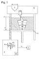
- Fig. 1
- detecting a failure in generatively producing a component according to a method and by means of an apparatus according to an embodiment of the present invention.
Die Vorrichtung weist ein Positionserfassungsmittel 6 zum Erfassen einer Positionsänderung z(t) der Position z der Plattform über der Zeit in Schichtaufbaurichtung relativ zu einer Referenz z0, die zu einer Führung 23 des Schiebers und Lasers ortsfest ist, durch Abtasten der Position der Plattform in Schichtaufbaurichtung mit einer Abtastfrequenz von beispielsweise 1 oder 10 kHz auf. Es sei darauf hingewiesen, dass die Position(s)änderung relativ zu verschiedensten Referenzen definiert sein bzw. erfasst werden kann, wobei eine solche Referenz, wie im Ausführungsbeispiel angedeutet, vorzugsweise ortsfest gegenüber einer Führung des Verteilungs- und/oder des Bindemittels ist, insbesondere um Bewegungen der gesamten Vorrichtung gegenüber ihrer Umgebung zu kompensieren.The apparatus comprises a position detecting means 6 for detecting a positional change z (t) of the position z of the platform over time in the layering direction relative to a reference z 0 fixed to a
Das Positionserfassungsmittel weist ein Steuermittel 6A zum Regeln und/oder Kontrollieren des Absenkens der Plattform auf.The position detecting means comprises a control means 6A for controlling and / or controlling the lowering of the platform.
Die Vorrichtung weist weiter ein Störungserfassungsmittel 7 zum Erfassen, ob die Bewegung des Verteilungsmittels störungsfrei ist oder nicht, auf.The apparatus further includes a trouble detection means 7 for detecting whether the movement of the distribution means is trouble-free or not.
Das Positionserfassungsmittel erfasst während einer Bewegung des Verteilungsmittels eine Schwingungsamplitude A der Positionsänderung z(t) der Plattform und übermittelt diese an das Störungserfassungsmittel.The position detecting means detects during a movement of the distribution means a vibration amplitude A of the position change z (t) of the platform and transmits them to the interference detection means.
Kollidiert das Verteilungsmittel bei seiner Bewegung zum Anordnen der Ausgangsmaterialschicht mit einem Hindernis, wie in
Entsprechend erfasst in diesem Fall das Störungserfassungsmittel, dass die Bewegung des Verteilungsmittels nicht (mehr) störungsfrei ist, und löst eine Reaktion aus, beispielsweise ein weiteres Absenken der Plattform, eine Verlangsamung oder Unterbrechung der Bewegung des Verteilungsmittels und/oder ein Warnsignal; eventuell kann auch eine Wiederholung des Verteilungsvorganges ausgelöst werden.Accordingly, in this case, the fault detection means detects that the movement of the distribution means is not (more) trouble-free and triggers a response, for example further lowering of the platform, slowing down or interrupting the movement of the distribution means and / or a warning signal; possibly also a repetition of the distribution process can be triggered.
Obwohl in der vorhergehenden Beschreibung exemplarische Ausführungen erläutert wurden, sei darauf hingewiesen, dass eine Vielzahl von Abwandlungen möglich ist. Außerdem sei darauf hingewiesen, dass es sich bei den exemplarischen Ausführungen lediglich um Beispiele handelt, die den Schutzbereich, die Anwendungen und den Aufbau in keiner Weise einschränken sollen. Vielmehr wird dem Fachmann durch die vorausgehende Beschreibung ein Leitfaden für die Umsetzung von mindestens einer exemplarischen Ausführung gegeben, wobei diverse Änderungen, insbesondere in Hinblick auf die Funktion und Anordnung der beschriebenen Bestandteile, vorgenommen werden können, ohne den Schutzbereich zu verlassen, wie er sich aus den Ansprüchen und diesen äquivalenten Merkmalskombinationen ergibt.Although exemplary embodiments have been explained in the foregoing description, it should be understood that a variety of modifications are possible. It should also be noted that the exemplary embodiments are merely examples that are not intended to limit the scope, applications and construction in any way. Rather, the expert is given by the preceding description, a guide for the implementation of at least one exemplary embodiment, with various changes, in particular with regard to the function and arrangement of the components described, can be made without departing from the scope, as it turns out according to the claims and these equivalent combinations of features.
- 11
- Schieber (Verteilungsmittel)Slider (distribution means)
- 22
- AusgangsmaterialschichtRaw material layer
- 33
- Laser (Bindemittel)Laser (binder)
- 4A, 4B,...4A, 4B, ...
- Querschnitt des herzustellenden BauteilsCross section of the component to be produced
- 55
- Plattformplatform
- 66
- PositionserfassungsmittelPosition detection means
- 6A6A
- Steuermittelcontrol means
- 77
- StörungserfassungsmittelFault detection means
- 2323
- Führungguide
Claims (14)
dadurch gekennzeichnet, dass
auf Basis einer erfassten Position oder Positionsänderung, insbesondere Schwingung (z(t)), der Plattform, insbesondere in Schichtaufbaurichtung, erfasst wird, ob die Bewegung des Verteilungsmittels störungsfrei ist oder nicht.Method for generatively producing a component (4A, 4B,...), Wherein the steps:
characterized in that
is detected on the basis of a detected position or position change, in particular vibration (z (t)), the platform, in particular in the layer construction direction, whether the movement of the distribution means is trouble-free or not.
ein Positionserfassungsmittel (6) zum Erfassen einer Position oder Positionsänderung, insbesondere Schwingung (z(t)), der Plattform, insbesondere in Schichtaufbaurichtung; und einem Störungserfassungsmittel (7) zum Erfassen, ob die Bewegung des Verteilungsmittels störungsfrei ist oder nicht, auf Basis der erfassten Position bzw. Positionsänderung.Device for the generative production of a component (4A, 4B, ...) by means of a method according to one of the preceding claims, comprising:
a position detection means (6) for detecting a position or position change, in particular oscillation (z (t)) of the platform, in particular in the layer construction direction; and fault detection means (7) for detecting whether or not the movement of the distribution means is trouble-free based on the detected position.
Applications Claiming Priority (1)
| Application Number | Priority Date | Filing Date | Title |
|---|---|---|---|
| DE102014203710.7A DE102014203710B3 (en) | 2014-02-28 | 2014-02-28 | Device and method for the generative production of a component |
Publications (2)
| Publication Number | Publication Date |
|---|---|
| EP2913176A1 true EP2913176A1 (en) | 2015-09-02 |
| EP2913176B1 EP2913176B1 (en) | 2017-11-29 |
Family
ID=52273026
Family Applications (1)
| Application Number | Title | Priority Date | Filing Date |
|---|---|---|---|
| EP15150237.4A Active EP2913176B1 (en) | 2014-02-28 | 2015-01-07 | Apparatus and process for additive manufacturing of a work piece |
Country Status (3)
| Country | Link |
|---|---|
| US (1) | US9943907B2 (en) |
| EP (1) | EP2913176B1 (en) |
| DE (1) | DE102014203710B3 (en) |
Cited By (1)
| Publication number | Priority date | Publication date | Assignee | Title |
|---|---|---|---|---|
| EP3275631A1 (en) * | 2016-07-29 | 2018-01-31 | CL Schutzrechtsverwaltungs GmbH | Powder module for an apparatus for additive manufacturing of three-dimensional objects |
Families Citing this family (13)
| Publication number | Priority date | Publication date | Assignee | Title |
|---|---|---|---|---|
| JP5841652B1 (en) * | 2014-11-21 | 2016-01-13 | 株式会社ソディック | Additive manufacturing equipment |
| DE102015201796B3 (en) * | 2015-02-03 | 2016-06-02 | MTU Aero Engines AG | Powder application unit and corresponding device and use of a powder application unit |
| US10384439B2 (en) * | 2015-11-06 | 2019-08-20 | Stratasys, Inc. | Continuous liquid interface production system with viscosity pump |
| US20170144250A1 (en) * | 2015-11-19 | 2017-05-25 | General Electric Company | Real-time vibration monitoring of an additive manufacturing process |
| DE102016218249A1 (en) | 2016-09-22 | 2018-03-22 | Siemens Aktiengesellschaft | A method of producing a workpiece by an additive manufacturing method and apparatus suitable for carrying out the method |
| EP3431257B1 (en) * | 2017-07-21 | 2020-05-27 | CL Schutzrechtsverwaltungs GmbH | Apparatus for manufacturing three-dimensional objects |
| CN109421276A (en) * | 2017-08-30 | 2019-03-05 | 三纬国际立体列印科技股份有限公司 | The initial position compensation for calibrating errors method of three-dimensional printing machine |
| EP3473412A1 (en) * | 2017-10-20 | 2019-04-24 | CL Schutzrechtsverwaltungs GmbH | Apparatus and method for additively manufacturing of three-dimensional objects |
| EP3486085A1 (en) * | 2017-11-21 | 2019-05-22 | CL Schutzrechtsverwaltungs GmbH | Calibration device for an apparatus for additively manufacturing three-dimensional objects |
| CN112041149A (en) | 2018-06-18 | 2020-12-04 | 惠普发展公司,有限责任合伙企业 | Additive manufacturing |
| CN109822909A (en) * | 2019-03-28 | 2019-05-31 | 哈尔滨理工大学 | A kind of FDM3D printer optimization algorithm |
| CN110625219A (en) * | 2019-09-04 | 2019-12-31 | 上海工程技术大学 | Electric arc additive manufacturing process for thick-wall aluminum alloy structural parts with different thicknesses |
| DE102020202353A1 (en) | 2020-02-24 | 2021-08-26 | Eos Gmbh Electro Optical Systems | Method and device for determining the distance in an additive manufacturing device |
Citations (6)
| Publication number | Priority date | Publication date | Assignee | Title |
|---|---|---|---|---|
| EP2011631A1 (en) * | 2007-07-04 | 2009-01-07 | Envisiontec GmbH | Process and device for producing a three-dimensional object |
| WO2009013751A2 (en) | 2007-07-25 | 2009-01-29 | Objet Geometries Ltd. | Solid freeform fabrication using a plurality of modeling materials |
| US20090267269A1 (en) * | 2008-04-25 | 2009-10-29 | Jin Hong Lim | Selective Deposition Modeling Using CW UV LED Curing |
| WO2012045660A1 (en) | 2010-10-04 | 2012-04-12 | Huntsman Advanced Materials (Switzerland) Gmbh | System and resin for rapid prototyping |
| WO2013156119A1 (en) * | 2012-04-20 | 2013-10-24 | Eos Gmbh Electro Optical Systems | Method and device for producing components in a beam melting installation |
| DE102012014840A1 (en) * | 2012-07-27 | 2014-01-30 | Cl Schutzrechtsverwaltungs Gmbh | Device for producing three-dimensional objects by electromagnetic radiation or building material, comprises support device with a support for supporting object, coating device for applying building material layers and irradiation device |
Family Cites Families (3)
| Publication number | Priority date | Publication date | Assignee | Title |
|---|---|---|---|---|
| ATE370832T1 (en) * | 2003-05-01 | 2007-09-15 | Objet Geometries Ltd | RAPID PROTOTYPING APPARATUS |
| DE102005025348B4 (en) * | 2005-05-31 | 2007-08-02 | Trumpf Werkzeugmaschinen Gmbh + Co. Kg | Process for producing a shaped body and sensor unit for its implementation |
| WO2010043274A1 (en) * | 2008-10-17 | 2010-04-22 | Huntsman Advanced Materials (Switzerland) Gmbh | Improvements for rapid prototyping apparatus |
-
2014
- 2014-02-28 DE DE102014203710.7A patent/DE102014203710B3/en active Active
-
2015
- 2015-01-07 EP EP15150237.4A patent/EP2913176B1/en active Active
- 2015-02-23 US US14/628,402 patent/US9943907B2/en active Active
Patent Citations (6)
| Publication number | Priority date | Publication date | Assignee | Title |
|---|---|---|---|---|
| EP2011631A1 (en) * | 2007-07-04 | 2009-01-07 | Envisiontec GmbH | Process and device for producing a three-dimensional object |
| WO2009013751A2 (en) | 2007-07-25 | 2009-01-29 | Objet Geometries Ltd. | Solid freeform fabrication using a plurality of modeling materials |
| US20090267269A1 (en) * | 2008-04-25 | 2009-10-29 | Jin Hong Lim | Selective Deposition Modeling Using CW UV LED Curing |
| WO2012045660A1 (en) | 2010-10-04 | 2012-04-12 | Huntsman Advanced Materials (Switzerland) Gmbh | System and resin for rapid prototyping |
| WO2013156119A1 (en) * | 2012-04-20 | 2013-10-24 | Eos Gmbh Electro Optical Systems | Method and device for producing components in a beam melting installation |
| DE102012014840A1 (en) * | 2012-07-27 | 2014-01-30 | Cl Schutzrechtsverwaltungs Gmbh | Device for producing three-dimensional objects by electromagnetic radiation or building material, comprises support device with a support for supporting object, coating device for applying building material layers and irradiation device |
Cited By (2)
| Publication number | Priority date | Publication date | Assignee | Title |
|---|---|---|---|---|
| EP3275631A1 (en) * | 2016-07-29 | 2018-01-31 | CL Schutzrechtsverwaltungs GmbH | Powder module for an apparatus for additive manufacturing of three-dimensional objects |
| US10471701B2 (en) | 2016-07-29 | 2019-11-12 | Cl Schutzrechtsverwaltungs Gmbh | Powder module for an apparatus for additive manufacturing of three-dimensional objects |
Also Published As
| Publication number | Publication date |
|---|---|
| EP2913176B1 (en) | 2017-11-29 |
| US9943907B2 (en) | 2018-04-17 |
| US20150246414A1 (en) | 2015-09-03 |
| DE102014203710B3 (en) | 2015-05-28 |
Similar Documents
| Publication | Publication Date | Title |
|---|---|---|
| EP2913176B1 (en) | Apparatus and process for additive manufacturing of a work piece | |
| DE102012007791A1 (en) | Method and device for producing components in a jet melting plant | |
| EP3849740B1 (en) | Method and device for laser cutting a tailored blank from a continuously conveyed sheet strip | |
| DE102007062129B3 (en) | Method for producing a three-dimensional object | |
| EP2663417B1 (en) | Method of teaching / checking a sequence of movement of a welding robot, welding robot and associated controller | |
| DE102005059530B4 (en) | Command generation device | |
| EP2707159B1 (en) | Bending press with back gauge device and method for operating a bending press having a back gauge device | |
| EP2027962A1 (en) | Welding device and method for orbital welding of pipes | |
| EP1722197B1 (en) | Method and device for representing the location and the movement state of a load capable of oscillating | |
| EP3890916A1 (en) | Controlled powder deposit welding method | |
| EP3409636B1 (en) | Method for damping torsional vibrations of a load-bearing element of a lifting device | |
| DE112012004174T5 (en) | Laser processing device | |
| EP3275631B1 (en) | Powder module for an apparatus for additive manufacturing of three-dimensional objects | |
| WO2016015695A1 (en) | Camera-based determining of roughness for additively manufactured components | |
| EP1684046B1 (en) | Method and apparatus for measuring the distance between a sensor electrode and a workpiece | |
| WO2016030199A1 (en) | Method for puncturing metal workpieces by means of a laser beam and associated laser machining machine and computer program product | |
| EP3221486B1 (en) | Method and device for coating a metal strip with a coating material which is at first still liquid | |
| DE102011089061A1 (en) | Method for operating coordinate measuring device of portal construction type for measuring coordinates of workpiece, involves stopping movement of mechanism in direction driven by motor when current reaches and/or exceeds threshold value | |
| AT522480B1 (en) | Method for operating a processing system | |
| DE102017106559B4 (en) | Design or implementation of a movement task of a moving mass in a mechanical system along at least one axis of movement | |
| EP4007671A1 (en) | Welding system and welding method | |
| EP3132878B1 (en) | Arc welding method and welding power source for performing the method | |
| EP4045212A1 (en) | Method for operating a device for the additive manufacture of a three-dimensional object and method for creating a process window for carrying out said method | |
| DE102018124208A1 (en) | Method and device for monitoring a machining process of a workpiece by means of a laser beam | |
| WO2012051981A2 (en) | Component, in particular engine component, with an allocation characteristic and method |
Legal Events
| Date | Code | Title | Description |
|---|---|---|---|
| PUAI | Public reference made under article 153(3) epc to a published international application that has entered the european phase |
Free format text: ORIGINAL CODE: 0009012 |
|
| AK | Designated contracting states |
Kind code of ref document: A1 Designated state(s): AL AT BE BG CH CY CZ DE DK EE ES FI FR GB GR HR HU IE IS IT LI LT LU LV MC MK MT NL NO PL PT RO RS SE SI SK SM TR |
|
| AX | Request for extension of the european patent |
Extension state: BA ME |
|
| 17P | Request for examination filed |
Effective date: 20160127 |
|
| RBV | Designated contracting states (corrected) |
Designated state(s): AL AT BE BG CH CY CZ DE DK EE ES FI FR GB GR HR HU IE IS IT LI LT LU LV MC MK MT NL NO PL PT RO RS SE SI SK SM TR |
|
| GRAP | Despatch of communication of intention to grant a patent |
Free format text: ORIGINAL CODE: EPIDOSNIGR1 |
|
| INTG | Intention to grant announced |
Effective date: 20170626 |
|
| GRAS | Grant fee paid |
Free format text: ORIGINAL CODE: EPIDOSNIGR3 |
|
| GRAA | (expected) grant |
Free format text: ORIGINAL CODE: 0009210 |
|
| REG | Reference to a national code |
Ref country code: DE Ref legal event code: R108 |
|
| AK | Designated contracting states |
Kind code of ref document: B1 Designated state(s): AL AT BE BG CH CY CZ DK EE ES FI FR GB GR HR HU IE IS IT LI LT LU LV MC MK MT NL NO PL PT RO RS SE SI SK SM TR |
|
| RBV | Designated contracting states (corrected) |
Designated state(s): AL AT BE BG CH CY CZ DK EE ES FI FR GB GR HR HU IE IS IT LI LT LU LV MC MK MT NL NO PL PT RO RS SE SI SK SM TR |
|
| REG | Reference to a national code |
Ref country code: CH Ref legal event code: EP |
|
| REG | Reference to a national code |
Ref country code: AT Ref legal event code: REF Ref document number: 949996 Country of ref document: AT Kind code of ref document: T Effective date: 20171215 |
|
| REG | Reference to a national code |
Ref country code: IE Ref legal event code: FG4D Free format text: LANGUAGE OF EP DOCUMENT: GERMAN |
|
| REG | Reference to a national code |
Ref country code: FR Ref legal event code: PLFP Year of fee payment: 4 |
|
| REG | Reference to a national code |
Ref country code: NL Ref legal event code: MP Effective date: 20171129 |
|
| REG | Reference to a national code |
Ref country code: LT Ref legal event code: MG4D |
|
| PG25 | Lapsed in a contracting state [announced via postgrant information from national office to epo] |
Ref country code: NO Free format text: LAPSE BECAUSE OF FAILURE TO SUBMIT A TRANSLATION OF THE DESCRIPTION OR TO PAY THE FEE WITHIN THE PRESCRIBED TIME-LIMIT Effective date: 20180228 Ref country code: SE Free format text: LAPSE BECAUSE OF FAILURE TO SUBMIT A TRANSLATION OF THE DESCRIPTION OR TO PAY THE FEE WITHIN THE PRESCRIBED TIME-LIMIT Effective date: 20171129 Ref country code: ES Free format text: LAPSE BECAUSE OF FAILURE TO SUBMIT A TRANSLATION OF THE DESCRIPTION OR TO PAY THE FEE WITHIN THE PRESCRIBED TIME-LIMIT Effective date: 20171129 Ref country code: LT Free format text: LAPSE BECAUSE OF FAILURE TO SUBMIT A TRANSLATION OF THE DESCRIPTION OR TO PAY THE FEE WITHIN THE PRESCRIBED TIME-LIMIT Effective date: 20171129 Ref country code: FI Free format text: LAPSE BECAUSE OF FAILURE TO SUBMIT A TRANSLATION OF THE DESCRIPTION OR TO PAY THE FEE WITHIN THE PRESCRIBED TIME-LIMIT Effective date: 20171129 |
|
| PG25 | Lapsed in a contracting state [announced via postgrant information from national office to epo] |
Ref country code: GR Free format text: LAPSE BECAUSE OF FAILURE TO SUBMIT A TRANSLATION OF THE DESCRIPTION OR TO PAY THE FEE WITHIN THE PRESCRIBED TIME-LIMIT Effective date: 20180301 Ref country code: RS Free format text: LAPSE BECAUSE OF FAILURE TO SUBMIT A TRANSLATION OF THE DESCRIPTION OR TO PAY THE FEE WITHIN THE PRESCRIBED TIME-LIMIT Effective date: 20171129 Ref country code: LV Free format text: LAPSE BECAUSE OF FAILURE TO SUBMIT A TRANSLATION OF THE DESCRIPTION OR TO PAY THE FEE WITHIN THE PRESCRIBED TIME-LIMIT Effective date: 20171129 Ref country code: BG Free format text: LAPSE BECAUSE OF FAILURE TO SUBMIT A TRANSLATION OF THE DESCRIPTION OR TO PAY THE FEE WITHIN THE PRESCRIBED TIME-LIMIT Effective date: 20180228 Ref country code: HR Free format text: LAPSE BECAUSE OF FAILURE TO SUBMIT A TRANSLATION OF THE DESCRIPTION OR TO PAY THE FEE WITHIN THE PRESCRIBED TIME-LIMIT Effective date: 20171129 |
|
| PG25 | Lapsed in a contracting state [announced via postgrant information from national office to epo] |
Ref country code: NL Free format text: LAPSE BECAUSE OF FAILURE TO SUBMIT A TRANSLATION OF THE DESCRIPTION OR TO PAY THE FEE WITHIN THE PRESCRIBED TIME-LIMIT Effective date: 20171129 |
|
| PG25 | Lapsed in a contracting state [announced via postgrant information from national office to epo] |
Ref country code: CZ Free format text: LAPSE BECAUSE OF FAILURE TO SUBMIT A TRANSLATION OF THE DESCRIPTION OR TO PAY THE FEE WITHIN THE PRESCRIBED TIME-LIMIT Effective date: 20171129 Ref country code: SK Free format text: LAPSE BECAUSE OF FAILURE TO SUBMIT A TRANSLATION OF THE DESCRIPTION OR TO PAY THE FEE WITHIN THE PRESCRIBED TIME-LIMIT Effective date: 20171129 Ref country code: DK Free format text: LAPSE BECAUSE OF FAILURE TO SUBMIT A TRANSLATION OF THE DESCRIPTION OR TO PAY THE FEE WITHIN THE PRESCRIBED TIME-LIMIT Effective date: 20171129 Ref country code: EE Free format text: LAPSE BECAUSE OF FAILURE TO SUBMIT A TRANSLATION OF THE DESCRIPTION OR TO PAY THE FEE WITHIN THE PRESCRIBED TIME-LIMIT Effective date: 20171129 Ref country code: CY Free format text: LAPSE BECAUSE OF FAILURE TO SUBMIT A TRANSLATION OF THE DESCRIPTION OR TO PAY THE FEE WITHIN THE PRESCRIBED TIME-LIMIT Effective date: 20171129 |
|
| PG25 | Lapsed in a contracting state [announced via postgrant information from national office to epo] |
Ref country code: RO Free format text: LAPSE BECAUSE OF FAILURE TO SUBMIT A TRANSLATION OF THE DESCRIPTION OR TO PAY THE FEE WITHIN THE PRESCRIBED TIME-LIMIT Effective date: 20171129 Ref country code: IT Free format text: LAPSE BECAUSE OF FAILURE TO SUBMIT A TRANSLATION OF THE DESCRIPTION OR TO PAY THE FEE WITHIN THE PRESCRIBED TIME-LIMIT Effective date: 20171129 Ref country code: PL Free format text: LAPSE BECAUSE OF FAILURE TO SUBMIT A TRANSLATION OF THE DESCRIPTION OR TO PAY THE FEE WITHIN THE PRESCRIBED TIME-LIMIT Effective date: 20171129 Ref country code: SM Free format text: LAPSE BECAUSE OF FAILURE TO SUBMIT A TRANSLATION OF THE DESCRIPTION OR TO PAY THE FEE WITHIN THE PRESCRIBED TIME-LIMIT Effective date: 20171129 |
|
| REG | Reference to a national code |
Ref country code: CH Ref legal event code: PL |
|
| PG25 | Lapsed in a contracting state [announced via postgrant information from national office to epo] |
Ref country code: MT Free format text: LAPSE BECAUSE OF FAILURE TO SUBMIT A TRANSLATION OF THE DESCRIPTION OR TO PAY THE FEE WITHIN THE PRESCRIBED TIME-LIMIT Effective date: 20171129 |
|
| PLBE | No opposition filed within time limit |
Free format text: ORIGINAL CODE: 0009261 |
|
| STAA | Information on the status of an ep patent application or granted ep patent |
Free format text: STATUS: NO OPPOSITION FILED WITHIN TIME LIMIT |
|
| PG25 | Lapsed in a contracting state [announced via postgrant information from national office to epo] |
Ref country code: LU Free format text: LAPSE BECAUSE OF NON-PAYMENT OF DUE FEES Effective date: 20180107 |
|
| REG | Reference to a national code |
Ref country code: IE Ref legal event code: MM4A |
|
| 26N | No opposition filed |
Effective date: 20180830 |
|
| REG | Reference to a national code |
Ref country code: BE Ref legal event code: MM Effective date: 20180131 |
|
| PG25 | Lapsed in a contracting state [announced via postgrant information from national office to epo] |
Ref country code: BE Free format text: LAPSE BECAUSE OF NON-PAYMENT OF DUE FEES Effective date: 20180131 Ref country code: SI Free format text: LAPSE BECAUSE OF FAILURE TO SUBMIT A TRANSLATION OF THE DESCRIPTION OR TO PAY THE FEE WITHIN THE PRESCRIBED TIME-LIMIT Effective date: 20171129 Ref country code: CH Free format text: LAPSE BECAUSE OF NON-PAYMENT OF DUE FEES Effective date: 20180131 Ref country code: LI Free format text: LAPSE BECAUSE OF NON-PAYMENT OF DUE FEES Effective date: 20180131 |
|
| PG25 | Lapsed in a contracting state [announced via postgrant information from national office to epo] |
Ref country code: IE Free format text: LAPSE BECAUSE OF NON-PAYMENT OF DUE FEES Effective date: 20180107 |
|
| PG25 | Lapsed in a contracting state [announced via postgrant information from national office to epo] |
Ref country code: MC Free format text: LAPSE BECAUSE OF FAILURE TO SUBMIT A TRANSLATION OF THE DESCRIPTION OR TO PAY THE FEE WITHIN THE PRESCRIBED TIME-LIMIT Effective date: 20171129 |
|
| PG25 | Lapsed in a contracting state [announced via postgrant information from national office to epo] |
Ref country code: TR Free format text: LAPSE BECAUSE OF FAILURE TO SUBMIT A TRANSLATION OF THE DESCRIPTION OR TO PAY THE FEE WITHIN THE PRESCRIBED TIME-LIMIT Effective date: 20171129 |
|
| PG25 | Lapsed in a contracting state [announced via postgrant information from national office to epo] |
Ref country code: PT Free format text: LAPSE BECAUSE OF FAILURE TO SUBMIT A TRANSLATION OF THE DESCRIPTION OR TO PAY THE FEE WITHIN THE PRESCRIBED TIME-LIMIT Effective date: 20171129 |
|
| PG25 | Lapsed in a contracting state [announced via postgrant information from national office to epo] |
Ref country code: HU Free format text: LAPSE BECAUSE OF FAILURE TO SUBMIT A TRANSLATION OF THE DESCRIPTION OR TO PAY THE FEE WITHIN THE PRESCRIBED TIME-LIMIT; INVALID AB INITIO Effective date: 20150107 Ref country code: MK Free format text: LAPSE BECAUSE OF NON-PAYMENT OF DUE FEES Effective date: 20171129 |
|
| PG25 | Lapsed in a contracting state [announced via postgrant information from national office to epo] |
Ref country code: AL Free format text: LAPSE BECAUSE OF FAILURE TO SUBMIT A TRANSLATION OF THE DESCRIPTION OR TO PAY THE FEE WITHIN THE PRESCRIBED TIME-LIMIT Effective date: 20171129 Ref country code: IS Free format text: LAPSE BECAUSE OF FAILURE TO SUBMIT A TRANSLATION OF THE DESCRIPTION OR TO PAY THE FEE WITHIN THE PRESCRIBED TIME-LIMIT Effective date: 20180329 |
|
| REG | Reference to a national code |
Ref country code: AT Ref legal event code: MM01 Ref document number: 949996 Country of ref document: AT Kind code of ref document: T Effective date: 20200107 |
|
| PG25 | Lapsed in a contracting state [announced via postgrant information from national office to epo] |
Ref country code: AT Free format text: LAPSE BECAUSE OF NON-PAYMENT OF DUE FEES Effective date: 20200107 |
|
| PGFP | Annual fee paid to national office [announced via postgrant information from national office to epo] |
Ref country code: FR Payment date: 20230123 Year of fee payment: 9 |
|
| PGFP | Annual fee paid to national office [announced via postgrant information from national office to epo] |
Ref country code: GB Payment date: 20230124 Year of fee payment: 9 |