EP2912996B1 - Blood pressure measuring apparatus and method - Google Patents
Blood pressure measuring apparatus and method Download PDFInfo
- Publication number
- EP2912996B1 EP2912996B1 EP15155742.8A EP15155742A EP2912996B1 EP 2912996 B1 EP2912996 B1 EP 2912996B1 EP 15155742 A EP15155742 A EP 15155742A EP 2912996 B1 EP2912996 B1 EP 2912996B1
- Authority
- EP
- European Patent Office
- Prior art keywords
- pressure
- waveform
- pulse wave
- artery
- data
- Prior art date
- Legal status (The legal status is an assumption and is not a legal conclusion. Google has not performed a legal analysis and makes no representation as to the accuracy of the status listed.)
- Active
Links
- 238000000034 method Methods 0.000 title claims description 94
- 230000036772 blood pressure Effects 0.000 title claims description 66
- 210000001367 artery Anatomy 0.000 claims description 97
- 230000000241 respiratory effect Effects 0.000 claims description 86
- 230000004872 arterial blood pressure Effects 0.000 claims description 29
- 210000003462 vein Anatomy 0.000 claims description 28
- 230000035487 diastolic blood pressure Effects 0.000 claims description 24
- 238000009530 blood pressure measurement Methods 0.000 claims description 19
- 230000003247 decreasing effect Effects 0.000 claims description 15
- 238000001514 detection method Methods 0.000 claims description 5
- 238000005259 measurement Methods 0.000 description 25
- 230000035488 systolic blood pressure Effects 0.000 description 15
- 230000000004 hemodynamic effect Effects 0.000 description 14
- 238000012544 monitoring process Methods 0.000 description 4
- 239000008280 blood Substances 0.000 description 3
- 210000004369 blood Anatomy 0.000 description 3
- 210000004204 blood vessel Anatomy 0.000 description 3
- 230000007423 decrease Effects 0.000 description 3
- 239000000284 extract Substances 0.000 description 3
- 230000029058 respiratory gaseous exchange Effects 0.000 description 3
- 238000010586 diagram Methods 0.000 description 2
- 238000003745 diagnosis Methods 0.000 description 1
- 230000003205 diastolic effect Effects 0.000 description 1
- 239000004973 liquid crystal related substance Substances 0.000 description 1
- 230000002035 prolonged effect Effects 0.000 description 1
- 230000035485 pulse pressure Effects 0.000 description 1
Images


Classifications
-
- A—HUMAN NECESSITIES
- A61—MEDICAL OR VETERINARY SCIENCE; HYGIENE
- A61B—DIAGNOSIS; SURGERY; IDENTIFICATION
- A61B5/00—Measuring for diagnostic purposes; Identification of persons
- A61B5/02—Detecting, measuring or recording pulse, heart rate, blood pressure or blood flow; Combined pulse/heart-rate/blood pressure determination; Evaluating a cardiovascular condition not otherwise provided for, e.g. using combinations of techniques provided for in this group with electrocardiography or electroauscultation; Heart catheters for measuring blood pressure
- A61B5/021—Measuring pressure in heart or blood vessels
- A61B5/022—Measuring pressure in heart or blood vessels by applying pressure to close blood vessels, e.g. against the skin; Ophthalmodynamometers
-
- A—HUMAN NECESSITIES
- A61—MEDICAL OR VETERINARY SCIENCE; HYGIENE
- A61B—DIAGNOSIS; SURGERY; IDENTIFICATION
- A61B5/00—Measuring for diagnostic purposes; Identification of persons
- A61B5/02—Detecting, measuring or recording pulse, heart rate, blood pressure or blood flow; Combined pulse/heart-rate/blood pressure determination; Evaluating a cardiovascular condition not otherwise provided for, e.g. using combinations of techniques provided for in this group with electrocardiography or electroauscultation; Heart catheters for measuring blood pressure
- A61B5/0205—Simultaneously evaluating both cardiovascular conditions and different types of body conditions, e.g. heart and respiratory condition
-
- A—HUMAN NECESSITIES
- A61—MEDICAL OR VETERINARY SCIENCE; HYGIENE
- A61B—DIAGNOSIS; SURGERY; IDENTIFICATION
- A61B5/00—Measuring for diagnostic purposes; Identification of persons
- A61B5/02—Detecting, measuring or recording pulse, heart rate, blood pressure or blood flow; Combined pulse/heart-rate/blood pressure determination; Evaluating a cardiovascular condition not otherwise provided for, e.g. using combinations of techniques provided for in this group with electrocardiography or electroauscultation; Heart catheters for measuring blood pressure
- A61B5/021—Measuring pressure in heart or blood vessels
- A61B5/02108—Measuring pressure in heart or blood vessels from analysis of pulse wave characteristics
-
- A—HUMAN NECESSITIES
- A61—MEDICAL OR VETERINARY SCIENCE; HYGIENE
- A61B—DIAGNOSIS; SURGERY; IDENTIFICATION
- A61B5/00—Measuring for diagnostic purposes; Identification of persons
- A61B5/02—Detecting, measuring or recording pulse, heart rate, blood pressure or blood flow; Combined pulse/heart-rate/blood pressure determination; Evaluating a cardiovascular condition not otherwise provided for, e.g. using combinations of techniques provided for in this group with electrocardiography or electroauscultation; Heart catheters for measuring blood pressure
- A61B5/021—Measuring pressure in heart or blood vessels
- A61B5/022—Measuring pressure in heart or blood vessels by applying pressure to close blood vessels, e.g. against the skin; Ophthalmodynamometers
- A61B5/02225—Measuring pressure in heart or blood vessels by applying pressure to close blood vessels, e.g. against the skin; Ophthalmodynamometers using the oscillometric method
-
- A—HUMAN NECESSITIES
- A61—MEDICAL OR VETERINARY SCIENCE; HYGIENE
- A61B—DIAGNOSIS; SURGERY; IDENTIFICATION
- A61B5/00—Measuring for diagnostic purposes; Identification of persons
- A61B5/08—Detecting, measuring or recording devices for evaluating the respiratory organs
- A61B5/0816—Measuring devices for examining respiratory frequency
-
- A—HUMAN NECESSITIES
- A61—MEDICAL OR VETERINARY SCIENCE; HYGIENE
- A61B—DIAGNOSIS; SURGERY; IDENTIFICATION
- A61B5/00—Measuring for diagnostic purposes; Identification of persons
- A61B5/72—Signal processing specially adapted for physiological signals or for diagnostic purposes
- A61B5/7203—Signal processing specially adapted for physiological signals or for diagnostic purposes for noise prevention, reduction or removal
-
- A—HUMAN NECESSITIES
- A61—MEDICAL OR VETERINARY SCIENCE; HYGIENE
- A61B—DIAGNOSIS; SURGERY; IDENTIFICATION
- A61B5/00—Measuring for diagnostic purposes; Identification of persons
- A61B5/72—Signal processing specially adapted for physiological signals or for diagnostic purposes
- A61B5/7221—Determining signal validity, reliability or quality
-
- A—HUMAN NECESSITIES
- A61—MEDICAL OR VETERINARY SCIENCE; HYGIENE
- A61B—DIAGNOSIS; SURGERY; IDENTIFICATION
- A61B5/00—Measuring for diagnostic purposes; Identification of persons
- A61B5/72—Signal processing specially adapted for physiological signals or for diagnostic purposes
- A61B5/7271—Specific aspects of physiological measurement analysis
- A61B5/7278—Artificial waveform generation or derivation, e.g. synthesising signals from measured signals
-
- A—HUMAN NECESSITIES
- A61—MEDICAL OR VETERINARY SCIENCE; HYGIENE
- A61B—DIAGNOSIS; SURGERY; IDENTIFICATION
- A61B5/00—Measuring for diagnostic purposes; Identification of persons
- A61B5/74—Details of notification to user or communication with user or patient ; user input means
- A61B5/742—Details of notification to user or communication with user or patient ; user input means using visual displays
Definitions
- the present invention relates to a blood pressure measuring apparatus and a blood pressure measuring method for measuring a blood pressure by using an oscillometric method.
- a respiratory variation on the waveform of artery and a central venous pressure are important indexes.
- a catheter is inserted to measure a correct central venous pressure.
- the measuring method is invasive, an excessive burden may be applied to a subject being tested. Also, a measuring apparatus is enlarged and a measurement time is prolonged. For this reason, a method for measuring the central venous pressure by a non-invasive and simple method has been suggested.
- JP-A-2012-205822 discloses measuring an mean venous pressure by using an oscillometric principle.
- JP-A-2011-511686 discloses measuring an arterial pressure and a pulse pressure variation (a respiratory variation on the waveform of artery) within a respiratory period by an oscillometric blood pressure measurement.
- US 5 094 244 relates to an apparatus and process for automatically measuring systolic, diastolic and mean arterial blood pressure.
- the configuration (1) it is possible to obtain the parameters of the respiratory variation on the waveform of artery and the venous pressure at once based on the applied pressure and the pulse wave components overlapping with the applied pressure in one-time blood pressure measurement. For this reason, it is possible to obtain the respective parameters in a non-invasive and simple manner in a series of measuring processes. Also, since the two parameters are obtained based on the applied pressure and the pulse wave components obtained in one-time blood pressure measurement, it is possible to obtain the parameters having higher relativity, as compared to a configuration where the parameters are obtained based on the applied pressure and the pulse wave components obtained by measurement of a separate measuring process or by mounting the cuff to a separate region.
- the applied pressure in the first process is equal to or lower than a diastolic blood pressure and within a range which does not include a pulse wave component of the vein in the pulse wave components.
- the applied pressure is kept at a pressure equal to or lower than the diastolic blood pressure and not including the pulse wave components of the vein, it is possible to obtain the respiratory variation on the waveform of artery more correctly.
- the analysis unit is configured to obtain the venous pressure based on the data of the pressure waveform in the second process when correlativity between the data of the pressure waveform in the second process and the data of the pressure waveform in the first process is low.
- the venous pressure is obtained based on the data of the pressure waveform in the second process having low correlativity with respect to the data of the pressure waveform in the first process, it is possible to suppress an influence of the arterial pressure, thereby obtaining the venous pressure more correctly.
- the analysis unit is configured to obtain an arterial pressure by one-time blood pressure measurement and based on data of a third pressure waveform of the pressure waveforms in a third process, in which the applied pressure is increased or decreased by the pressure control unit.
- the configuration (4) it is possible to obtain the three parameters of the arterial pressure, the respiratory variation on the waveform of artery and the venous pressure at once in one-time blood pressure measurement. For this reason, it is possible to obtain the respective parameters in a non-invasive and simple manner in a series of measuring processes. Also, when obtaining the arterial pressure during a time period for which the applied pressure is increased, it is possible to complete the measurement of the arterial pressure in a short time. Therefore, since it is possible to secure the longer time necessary for obtaining the respiratory variation on the waveform of artery and the venous pressure in the series of measuring processes, it is possible to obtain the three parameters securely and correctly.
- the analysis unit is configured to obtain the venous pressure based on the data of the second pressure waveform in the second process and the data of the third pressure waveform in the third process or the data of the first pressure waveform in the first process.
- the venous pressure is obtained based on any one of the data of the pressure waveform in the first process and the data of the pressure waveform in the third process, a choice of calculation is increased. Thereby, it is possible to sufficiently check the relativity with the pulse wave components of the arterial pressure, thereby obtaining the venous pressure more correctly.
- the analysis unit is configured to obtain the venous pressure based on the data of the second pressure waveform in the second process when a correlativity between the data of the second pressure waveform in the second process and the data of the third pressure waveform in the third process or the data of the first pressure waveform in the first process is low.
- the venous pressure is obtained based on the data of the pressure waveform in the second process having low correlativity with respect to one of the data of the waveforms in the first and third processes, it is possible to suppress the influence of the arterial pressure, thereby obtaining the venous pressure more correctly.
- the blood pressure measuring apparatus further includes a display unit, and a display control unit that controls the display unit.
- the display control unit is configured to display a value of the obtained respiratory variation on the waveform of artery and a value of the obtained venous pressure with a two-dimensional graph on the display unit.
- the configuration (7) since a relativity between the obtained value of the respiratory variation on the waveform of artery and the obtained value of the venous pressure is displayed as the two-dimensional graph on the display unit, a medical staff who is monitoring the biological information can comprehensively determine the two parameters of the respiratory variation on the waveform of artery and the venous pressure by seeing the display unit, thereby correctly assessing the hemodynamics.
- a determination criterion for determining the displayed value of the respiratory variation on the waveform of artery and the displayed value of the venous pressure is displayed on the two-dimensional graph.
- the medical staff who is monitoring the biological information can easily assess the hemodynamics.
- a blood pressure measuring method for controlling an applied pressure applied to a region of a living body in which a vein and an artery exist by a cuff mountable to the region, detecting pressure waveforms in which pulse wave components are overlapped with the applied pressure, and obtaining a on the waveform of artery of an arterial pressure and a venous pressure based on the detected pressure waveforms includes obtaining the respiratory variation on the waveform of artery based on data of a first pressure waveform of the pressure waveforms in a first process, in which the applied pressure is kept at a constant pressure, and obtaining the venous pressure based on data of a second pressure waveform of the pressure waveforms in a second process, in which the applied pressure is decreased or increased, and the data of the first pressure waveform.
- the first process and the second process are performed by one-time blood pressure measurement.
- the configuration (9) it is possible to obtain the parameters of the respiratory variation on the waveform of artery and the venous pressure at once based on the applied pressure and the pulse wave components overlapping with the applied pressure in one-time blood pressure measurement. For this reason, it is possible to obtain the respective parameters in a non-invasive and simple manner in a series of measuring processes. Also, since the two parameters are obtained based on the applied pressure and the pulse wave components obtained in one-time blood pressure measurement, it is possible to obtain the parameters having higher relativity, as compared to a configuration where the parameters are obtained based on the applied pressure and the pulse wave components obtained by measurement of a separate measuring process or by mounting the cuff to a separate region.
- the blood pressure measuring apparatus of the present invention it is possible to assess the hemodynamics of the living body simply and correctly.
- FIG. 1 is a functional block diagram showing a configuration of a blood pressure measuring apparatus 1.
- the blood pressure measuring apparatus 1 has a cuff 2, a pressure control unit 3, a pressure sensor (an example of a detection unit) 4, a pressure waveform analysis unit (an example of an analysis unit) 5, a determination unit 6, a display control unit 7 and a display unit 8.
- the cuff 2 is wound and mounted to a part of a living body at which the vein and artery of a subject being tested (an example of a living body) can be detected, for example, to a brachial region (an example of a region) in the vicinity of an axillary region.
- the cuff 2 has a pressure pouch (not shown), and a cuff pressure (an example of an applied pressure) is applied from the cuff 2 to the brachial region by an air pressure of the pressure pouch.
- the pressure control unit 3 is configured to control the air pressure of the pressure pouch of the cuff 2.
- the air pressure of the pressure pouch is controlled by a pressurization pump, an electromagnetic valve, a control circuit and the like included in the pressure control unit 3. All of them are not shown in the drawings.
- the pressure sensor 4 is configured to detect a pressure waveform in which pulse wave components overlap with the cuff pressure.
- a pulse wave which is a vibration of a blood vessel wall, overlaps with the cuff pressure in synchronization with the pulse of the subject being tested H.
- the pressure sensor 4 is configured to detect the pressure waveform in which the pulse wave components from the brachial region overlap, and to transmit the detected pressure waveform to the pressure waveform analysis unit 5.
- the pressure waveform analysis unit 5 is configured to obtain a diastolic blood pressure, an mean blood pressure and a systolic blood pressure (an example of an arterial pressure), a respiratory variation on the waveform of artery, and an mean venous pressure (an example of a venous pressure) measured at the vein of the brachial region in the vicinity of the axillary region, based on the cuff pressures and pulse wave components included in the pressure waveform.
- the pressure waveform analysis unit 5 is configured to obtain the respiratory variation on the waveform of artery and the mean venous pressure together with the blood pressure in one-time measuring process of measuring the blood pressure. In the meantime, it is said that the mean venous pressure measured at the vein of the brachial region is substantially equivalent to a central venous pressure measured by an invasive method.
- the determination unit 6 is configured to determine the reliability of the respiratory variation on the waveform of artery and mean venous pressure obtained by the pressure waveform analysis unit 5.
- the determination unit 6 is configured to determine the reliability by taking correlations between a representative pulse wave and the pulse waves overlapping with the respective cuff pressures during a time period for which the respiratory variation on the waveform of artery is obtained and during a time period for which the mean venous pressure is obtained.
- the display control unit 7 is configured to display on the display unit 8 the information of the diastolic blood pressure, the systolic blood pressure, the mean blood pressure, the respiratory variation on the waveform of artery, the mean venous pressure and the like.
- the display unit 8 is configured by a touch panel-type liquid crystal screen, for example.
- the measurement of the pulse wave component and the determination of the arterial pressure, the respiratory variation on the waveform of artery and the mean venous pressure are made substantially at the same time.
- the measurement of the cuff pressure and the pulse wave component may be first made and the determination of the arterial pressure, the respiratory variation on the waveform of artery and the mean venous pressure may be separately made using the data of the measured cuff pressure and the like.
- a blood pressure value is first measured (step S101).
- the blood pressure value is non-invasively measured by the oscillometric method.
- the cuff pressure of the cuff 2 wound on the brachial region is gradually or stepwise increased by the pressure control unit 3.
- a pressure waveform in the pressurization process (a third process) is detected by the pressure sensor 4, and the cuff pressures and pulse wave components (an example of data of the pressure waveform) included in the pressure waveform are measured and analyzed by the pressure waveform analysis unit 5.
- the pressure waveform analysis unit 5 obtains the diastolic blood pressure, the mean blood pressure and the systolic blood pressure based on a change in the pulse wave component.
- the pressure waveform analysis unit 5 determines, as the mean blood pressure, the cuff pressure at the time that the amplitude of the pulse wave component becomes largest.
- the pressure waveform analysis unit 5 obtains a pulse wave amplitude at the diastolic blood pressure and a pulse wave amplitude at the systolic blood pressure by a predetermined calculation equation, based on the maximum amplitude of the pulse wave component.
- the diastolic blood pressure is a cuff pressure lower than the mean blood pressure and is a cuff pressure at the time that the pulse wave amplitude being measured coincides with the pulse wave amplitude at the diastolic blood pressure obtained by the calculation equation.
- the systolic blood pressure is a cuff pressure higher than the mean blood pressure and is a cuff pressure at the time that the pulse wave amplitude being measured coincides with the pulse wave amplitude at the systolic blood pressure obtained by the calculation equation.
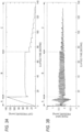
- FIG. 3 illustrates a change in the pressure detected during one-time measurement of the blood pressure measurement apparatus 1.
- FIG. 3A illustrates a change in the pressure waveform (in which the pulse wave components overlap with the cuff pressures) over elapsed measurement time of the blood pressure measuring apparatus 1.
- FIG. 3B illustrates the pulse wave components in the pressure waveform of FIG. 3A .
- the diastolic blood pressure, the mean blood pressure and the systolic blood pressure are measured during the pressurization process of the cuff pressure, which is a time period A shown in FIG. 3A .
- the measurement of the above blood pressures is completed at the time that the systolic blood pressure is measured.
- the blood pressure measurement during the time period A is completed at about 15 seconds after the measurement starts.
- the pressure waveform analysis unit 5 extracts the pulse wave component in the mean blood pressure of the blood pressures obtained in step S101, as a representative pulse wave component (step S102).
- FIG. 4 illustrates the pulse wave components during the time period A in FIG. 3 .
- the pulse wave component having the largest amplitude of the pulse wave components during the time period A is extracted as a representative pulse wave component a1, which is the pulse wave component of the mean blood pressure.
- the cuff pressure is reduced to a pressure within a range equal to or lower than the diastolic blood pressure and not including the pulse wave component of the vein, for example, 40 to 50 mmHg (step S103).
- the respiratory variation on the waveform of artery is obtained during a constant pressure (for example, about 50 mmHg) process (a first process) of the cuff pressure, which is a time period B shown in FIG. 3A .
- a constant pressure for example, about 50 mmHg
- a first process a first process of the cuff pressure
- the cuff pressure is kept at a constant pressure equal to or lower than the diastolic blood pressure continuously for a predetermined time period (for example, 60 seconds).
- the pressure that is kept constant is not limited to the pressure equal to or lower than the diastolic blood pressure inasmuch as an influence of the pulse of the venous pressure does not appear in the pressure.
- a pressure near the diastolic blood pressure may also be used.
- the determination unit 6 calculates correlation coefficients R1 between the pulse wave components overlapping with the cuff pressure kept at a constant pressure and the representative pulse wave component a1 extracted in step S102 (step S104).
- FIG. 5 illustrates the extracted pulse wave components during the time period B of FIG. 3 .
- individual pulse wave components b1, b2, b3,... are extracted by the pressure waveform analysis unit 5.
- the correlation coefficients R1 between the extracted individual pulse wave components b1, b2, b3,... and the representative pulse wave component a1 are calculated.
- the determination unit 6 extracts the pulse wave component having low correlativity based on the correlation coefficients R1, and excludes the extracted pulse wave component so that it is not used as a pulse wave component for obtaining the respiratory variation on the waveform of artery (step S105).
- the pulse wave component of the vein does not influence the pulse wave components b1, b2, b3,... during the time period B.
- the pulse wave components b1, b2, b3,..., which are not influenced by the pulse wave component of the vein have the high correlativity with the representative pulse wave component a1, which is a typical pulse wave of the artery.
- the pulse wave component having the low correlativity is excluded and the pulse wave component having the high correlativity is used as the pulse wave component for obtaining the respiratory variation on the waveform of artery.
- the pulse wave component having the high correlativity is used as the pulse wave component for obtaining the respiratory variation on the waveform of artery.
- the pressure waveform analysis unit 5 calculates amplitudes of the extracted pulse wave components b1, b2, b3,..., and calculates a respiratory period of the subject being tested H from a change in the amplitude (step S106). Then, it is determined whether 60 seconds have elapsed after the measurement of the respiratory variation on the waveform of artery has started (step S107). When 60 seconds have not elapsed, each step from step S104 is repeated. On the other hand, when 60 seconds have elapsed, the pressure waveform analysis unit 5 obtains the respiratory variation on the waveform of artery of the subject being tested H based on the amplitude variation of the pulse wave components during the plurality of calculated respiratory periods (step S108).
- Solid lines p shown in FIG 5 indicate envelope curves connecting peaks of the pulse wave components, and a time period T1 indicates the respiratory period. Also, an amplitude Hmax indicates a maximum amplitude of the pulse wave component, and an amplitude Hmin indicates a minimum amplitude of the pulse wave component.
- the respiratory variation on the waveform of artery is calculated by an equation of ((Hmax - Hmin)/((Hmax + Hmin)/2))*100[%]. By the calculation equation, the respiratory variation on the waveform of artery is calculated during the multiple respiratory periods.
- the measurement of the respiratory variation on the waveform of artery is completed at about 75 seconds after the measurement starts.
- the pressure control unit 3 stepwise (for example, by 5 mmHg) lowers the cuff pressure (step S109).
- the mean venous pressure is obtained in a depressurization process of the cuff pressure (a second process), which is a time period C shown in FIG. 3A .
- the mean venous pressure is measured continuously to the measurement of the respiratory variation on the waveform of artery, and the cuff pressure is stepwise reduced over time from the constant pressure (for example, about 50 mmHg) at which the respiratory variation on the waveform of artery is measured.
- the pressure waveform analysis unit 5 calculates the amplitudes of the pulse wave components overlapping with the cuff pressure reduced by 5 mmHg (step S110). Then, the determination unit 6 calculates correlation coefficients R2 between the pulse wave components overlapping with the cuff pressure reduced by 5 mmHg and the representative pulse wave component a1 extracted in step S102 (step S111).
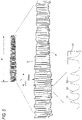
- FIG. 6 illustrates the extracted pulse wave components during the time period C of FIG. 3 .
- individual pulse wave components c1, c2, c3,... are extracted and amplitudes thereof are calculated.
- the correlation coefficients R2 between the extracted individual pulse wave components c1, c2, c3,... and the representative pulse wave component a1 are calculated.
- step S112 it is determined whether 6 seconds have elapsed after the cuff pressure is reduced by 5 mmHg.
- step S112 it is determined whether 6 seconds have elapsed after the measurement of the blood pressure has started.
- step S113 it is determined whether 140 seconds have elapsed after the measurement of the blood pressure has started.
- the pressure waveform analysis unit 5 obtains the mean venous pressure based on the amplitudes of the pulse wave components calculated in step S110 and the correlation coefficients R2 calculated in step S111 (step S114).
- the pulse wave components of the artery overlapping with the cuff pressure are correspondingly reduced and the pulse wave components of the vein are gradually increased.
- the correlation coefficient R2 with the representative pulse wave component a1 which is the typical pulse of the artery, is gradually decreased.
- the pulse wave components of the vein are further increased.
- the amplitudes of the pulse wave components of the vein show peaks. Based on this, the mean venous pressure is obtained by the pulse wave components of the second process and the correlativity between the pulse wave components of the second process and the pulse wave components of the first process.
- the pulse waveform analysis unit 5 performs the overall analysis on condition that the correlativity is low and the amplitude of the pulse wave component shows a peak, and determines the cuff pressure at that time, as the mean venous pressure. Then, the pressure waveform analysis unit estimates the determined mean venous pressure as a central venous pressure.
- the values of the respiratory variation on the waveform of artery and the values of the mean venous pressure obtained as described above are displayed as a two-dimensional graph on the display unit 8. Also, a determination criterion for determining the value of the respiratory variation on the waveform of artery and the value of the mean venous pressure is displayed as threshold lines m, n, for example.
- the hemodynamics of the subject being tested is determined as follows. For example, when the obtained value of the respiratory variation on the waveform of artery and the obtained value of the mean venous pressure are a point q on the graph, the value of the respiratory variation on the waveform of artery is below the threshold line n and the value of the mean venous pressure is above the threshold line m, it is determined that circulating blood volume is excessive. Also, for example, when the obtained values are a point r, the value of the respiratory variation on the waveform of artery is above the threshold line n and the value of the mean venous pressure is below the threshold line m, it is determined that circulating blood volume is insufficient.
- the values of the diastolic blood pressure, systolic blood pressure and mean blood pressure obtained as described above are also displayed simultaneously with the display of the two-dimensional graph on the display unit 8.
- the parameters of the diastolic blood pressure, mean blood pressure, systolic blood pressure, respiratory variation on the waveform of artery and mean venous pressure can be obtained at once based on the cuff pressure applied from the cuff 2 to the brachial region and the pulse wave components overlapping with the cuff pressure. For this reason, it is possible to obtain the respective parameters in a non-invasive and simple manner in a series of measuring processes.
- the relativity of the parameters is very high, as compared to a configuration where the parameters are obtained based on the cuff pressure and the pulse wave components overlapping with the cuff pressure obtained by measurement of a separate measuring process or by mounting the cuff 2 to a separate region. That is, while the respiratory variation on the waveform of artery and the mean venous pressure obtained by the method of the related art are the indexes having low reliability, it is possible to correctly assess the hemodynamics of the subject being tested H based on the parameters having high relativity, in accordance with the illustrative embodiment of the present invention.
- the diastolic blood pressure, mean blood pressure, systolic blood pressure are measured during the pressurization process of the cuff pressure, it is possible to shorten the time necessary to complete the measurement of the above blood pressures, as compared to a configuration where the cuff pressure is increased above the systolic blood pressure and the diastolic blood pressure, mean blood pressure, systolic blood pressure are measured during the depressurization process of the cuff pressure.
- the respiratory variation on the waveform of artery is obtained during the time period for which the cuff pressure is kept at a constant pressure, it is possible to clearly plot the envelope curves p connecting the peaks of the pulse wave components, so that it is possible to correctly obtain the variation components based on the respiration of the subject being tested, which are included in the pressure waveform. Also, since about 60 seconds are secured with respect to the time period for which the cuff pressure is kept at a constant pressure, it is possible to calculate the respiratory variation on the waveform of artery during the multiple respiratory periods, so that it is possible to obtain the more correct measurement result. Also, the cuff pressure is kept at the constant pressure within a range close to the diastolic blood pressure and not including the pulse wave components of the vein. Therefore, when obtaining the respiratory variation on the waveform of artery, the pulse of the vein little influences, so that it is possible to correctly extract the respiratory variation on the waveform of artery.
- the pulse wave components of the vein may overlap with the pulse wave components of the artery and may influence the same.
- the correlation coefficients R1 between the extracted pulse wave components b1, b2, b3, ⁇ and the representative pulse wave component a1, which is the typical pulse wave of the artery are calculated and the pulse wave component having low correlativity (a ratio that the pulse wave component of the vein overlaps is high) is excluded to improve the reliability of the respiratory variation on the waveform of artery.
- the pulse wave component having low correlativity is excluded based on the correlation coefficients R1 between the extracted pulse wave components b1, b2, b3, ⁇ obtained by one-time blood pressure measurement and the representative pulse wave component a1. Therefore, it is possible to obtain the respiratory variation on the waveform of artery by using the pulse wave components having higher relativity, as compared to a configuration where the respective blood pressures and the respiratory variation on the waveform of artery are obtained by measurements of separate measuring processes or by mounting the cuff 2 to separate regions, for example. Thereby, it is possible to obtain the respiratory variation on the waveform of artery having high reliability, so that it is possible to assess the correct hemodynamics.
- the mean venous pressure is obtained during the depressurization process of the cuff pressure, it is possible to observe the pulse wave components of the vein while gradually decreasing the pulse wave components of the arterial pressure. For this reason, it is possible to easily detect an amplitude variation in the pulse wave components of the vein, so that it is possible to correctly obtain the mean venous pressure. Also, since the cuff pressure is stepwise decreased, the electromagnetic valve less influences, as compared to a configuration where the cuff pressure is continuously decreased, so that it is possible to more correctly obtain the mean venous pressure.
- the correlation coefficients R2 between the extracted pulse wave components c1, c2, c3, ⁇ and the representative pulse wave component a1, which is a typical pulse wave of the artery are calculated and the pulse wave component having high correlativity (a ratio that the pulse wave component of the artery overlaps is high) is excluded based on the correlation coefficients R2.
- the pulse wave component having high correlativity is excluded based on the correlation coefficients R2 between the pulse wave components c1, c2, c3, ⁇ obtained by one-time blood pressure measurement and the representative pulse wave component a1. Therefore, it is possible to obtain the mean venous pressure by using the pulse wave components having higher relativity, as compared to a configuration where the respective blood pressures and the mean venous pressure are obtained by measurements of separate measuring processes or by mounting the cuff 2 to separate regions and the pulse wave component having high correlativity is excluded based on the correlation coefficients R2 of the pulse wave components extracted therefrom, for example. Thereby, it is possible to obtain the mean venous pressure less influenced by the arterial pressure and having high reliability, so that it is possible to assess the correct hemodynamics.
- the relativity between the obtained values of the respiratory variation on the waveform of artery and the obtained values of the venous pressure is displayed as the two-dimensional graph on the display unit 8
- a medical staff who is monitoring the biological information can comprehensively determine the two parameters of the respiratory variation on the waveform of artery and the venous pressure by seeing the display unit 8, thereby correctly assessing the hemodynamics of the subject being tested.
- the threshold lines m, n which are the criteria for determining the values of the respiratory variation on the waveform of artery and the values of the mean venous pressure, are displayed on the two-dimensional graph, the medical staff who is monitoring the biological information can easily assess the hemodynamics.
- the pulse wave components of the artery overlap with the pulse wave components of the vein at the time that the value of the diastolic blood pressure is low and the mean venous pressure is obtained
- the pulse wave components of the artery detected at the time that the respiratory variation on the waveform of artery is obtained are subtracted from the overlapping pulse wave components.
- the pulse wave components of the vein overlap with the pulse wave components of the artery at the time that the value of the diastolic blood pressure is low and the respiratory variation on the waveform of artery is obtained
- the pulse wave components of the artery detected upon the calculation of the mean venous pressure are subtracted after the calculation of the mean venous pressure is completed.
- the reduction of the cuff pressure during the time period C for which the mean venous pressure is obtained is not limited to the stepwise reduction and the cuff pressure may be continuously reduced. Further, the cuff pressure may be stepwise or continuously increased to obtain the mean venous pressure during the pressurization process (the second process). Also, when calculating the correlation coefficient R2 of the pulse wave components at the time that the mean venous pressure is obtained, the pulse wave component of the mean blood pressure is used as the representative pulse wave component a1. However, for example, any one of the pulse wave components b1, b2, b3, ⁇ having the highest correlativity with the representative pulse wave component a1 may be used as the representative pulse wave component when measuring the respiratory variation on the waveform of artery. In this case, since the pulse wave components b1, b2, b3 are closer upon the measurement of the mean venous pressure in the elapsed measuring time, it is possible to increase the correctness of the correlation coefficient R2.
- a representative pulse may be determined from the pulse wave components of the artery during the process of measuring the respiratory variation on the waveform of artery, a correlativity between the representative pulse and a pulse wave component for obtaining the mean venous pressure may be obtained to determine the pulse wave component for obtaining the mean venous pressure.
- the sequence of measuring the pulse wave components may not be the order of the arterial pressure, the respiratory variation on the waveform of artery and the mean venous pressure.
- the pulse wave components may be measured in order of the mean venous pressure, the respiratory variation on the waveform of artery and the arterial pressure. Also, only the respiratory variation on the waveform of artery and mean venous pressure may be measured.
Landscapes
- Health & Medical Sciences (AREA)
- Life Sciences & Earth Sciences (AREA)
- Engineering & Computer Science (AREA)
- Physiology (AREA)
- Public Health (AREA)
- Surgery (AREA)
- Veterinary Medicine (AREA)
- Physics & Mathematics (AREA)
- General Health & Medical Sciences (AREA)
- Biophysics (AREA)
- Pathology (AREA)
- Biomedical Technology (AREA)
- Heart & Thoracic Surgery (AREA)
- Medical Informatics (AREA)
- Molecular Biology (AREA)
- Animal Behavior & Ethology (AREA)
- Cardiology (AREA)
- Vascular Medicine (AREA)
- Signal Processing (AREA)
- Pulmonology (AREA)
- Psychiatry (AREA)
- Computer Vision & Pattern Recognition (AREA)
- Artificial Intelligence (AREA)
- Ophthalmology & Optometry (AREA)
- Measuring Pulse, Heart Rate, Blood Pressure Or Blood Flow (AREA)
Description
- The present invention relates to a blood pressure measuring apparatus and a blood pressure measuring method for measuring a blood pressure by using an oscillometric method.
- When assessing hemodynamics, a respiratory variation on the waveform of artery and a central venous pressure are important indexes. In the related art, in order to obtain the central venous pressure, for example, a catheter is inserted to measure a correct central venous pressure. However, since the measuring method is invasive, an excessive burden may be applied to a subject being tested. Also, a measuring apparatus is enlarged and a measurement time is prolonged. For this reason, a method for measuring the central venous pressure by a non-invasive and simple method has been suggested.
- For example,
JP-A-2012-205822 JP-A-2011-511686 - However, since the mean venous pressure measured by the method disclosed in
JP-A-2012-205822 JP-A-2011-511686 -
US 5 094 244 relates to an apparatus and process for automatically measuring systolic, diastolic and mean arterial blood pressure. - It is therefore an object of the present invention to provide a blood pressure measuring apparatus and a blood pressure measuring method capable of simply and correctly assessing hemodynamics of a living body.
- The invention is as specified in the appended claims.
- Configurations not according to the invention:
- (1) A blood pressure measuring apparatus includes a pressure control unit that controls an applied pressure applied to a region of a living body in which a vein and artery exist by a cuff mountable to the region, a detection unit that detects pressure waveforms in which pulse wave components from the region overlap with the applied pressure, and an analysis unit that obtains a respiratory variation on the waveform of artery and a venous pressure based on the pressure waveforms detected by the detection unit through one-time blood pressure measurement. The analysis unit obtains the respiratory variation on the waveform of artery based on data of a first pressure waveform of the pressure waveforms in a first process, in which the applied pressure is kept at a constant pressure by the pressure control unit, and the venous pressure based on data of a second pressure waveform of the pressure waveforms in a second process in which the applied pressure is decreased or increased by the pressure control unit, and the data of the first pressure waveform in the first process.
- According to the configuration (1), it is possible to obtain the parameters of the respiratory variation on the waveform of artery and the venous pressure at once based on the applied pressure and the pulse wave components overlapping with the applied pressure in one-time blood pressure measurement. For this reason, it is possible to obtain the respective parameters in a non-invasive and simple manner in a series of measuring processes. Also, since the two parameters are obtained based on the applied pressure and the pulse wave components obtained in one-time blood pressure measurement, it is possible to obtain the parameters having higher relativity, as compared to a configuration where the parameters are obtained based on the applied pressure and the pulse wave components obtained by measurement of a separate measuring process or by mounting the cuff to a separate region. Therefore, it is possible to correctly assess the hemodynamics based on the parameters having high relativity. Also, since the respiratory variation on the waveform of artery is obtained during a time period for which the applied pressure is controlled at a constant pressure, it is possible to correctly obtain variation components based on the respiration, which are included in the pressure waveform. Also, since the venous pressure is obtained during a time period for which the applied pressure is decreased or increased, it is possible to gradually change (decrease or increase) the pulse wave components of the arterial pressure included in the pressure waveform, thereby correctly obtaining the venous pressure.
- (2) In the blood pressure measuring apparatus of (1), the applied pressure in the first process is equal to or lower than a diastolic blood pressure and within a range which does not include a pulse wave component of the vein in the pulse wave components.
- According to the configuration (2), since the applied pressure is kept at a pressure equal to or lower than the diastolic blood pressure and not including the pulse wave components of the vein, it is possible to obtain the respiratory variation on the waveform of artery more correctly.
- (3) In the blood pressure measuring apparatus of (1) or (2), the analysis unit is configured to obtain the venous pressure based on the data of the pressure waveform in the second process when correlativity between the data of the pressure waveform in the second process and the data of the pressure waveform in the first process is low.
- According to the configuration (3), since the venous pressure is obtained based on the data of the pressure waveform in the second process having low correlativity with respect to the data of the pressure waveform in the first process, it is possible to suppress an influence of the arterial pressure, thereby obtaining the venous pressure more correctly.
- (4) In the blood pressure measuring apparatus of (1) or (2), the analysis unit is configured to obtain an arterial pressure by one-time blood pressure measurement and based on data of a third pressure waveform of the pressure waveforms in a third process, in which the applied pressure is increased or decreased by the pressure control unit.
- According to the configuration (4), it is possible to obtain the three parameters of the arterial pressure, the respiratory variation on the waveform of artery and the venous pressure at once in one-time blood pressure measurement. For this reason, it is possible to obtain the respective parameters in a non-invasive and simple manner in a series of measuring processes. Also, when obtaining the arterial pressure during a time period for which the applied pressure is increased, it is possible to complete the measurement of the arterial pressure in a short time. Therefore, since it is possible to secure the longer time necessary for obtaining the respiratory variation on the waveform of artery and the venous pressure in the series of measuring processes, it is possible to obtain the three parameters securely and correctly.
- (5) In the blood pressure measuring apparatus of (4), the analysis unit is configured to obtain the venous pressure based on the data of the second pressure waveform in the second process and the data of the third pressure waveform in the third process or the data of the first pressure waveform in the first process.
- According to the configuration (5), since the venous pressure is obtained based on any one of the data of the pressure waveform in the first process and the data of the pressure waveform in the third process, a choice of calculation is increased. Thereby, it is possible to sufficiently check the relativity with the pulse wave components of the arterial pressure, thereby obtaining the venous pressure more correctly.
- (6) In the blood pressure measuring apparatus of (5), the analysis unit is configured to obtain the venous pressure based on the data of the second pressure waveform in the second process when a correlativity between the data of the second pressure waveform in the second process and the data of the third pressure waveform in the third process or the data of the first pressure waveform in the first process is low.
- According to the configuration (6), since the venous pressure is obtained based on the data of the pressure waveform in the second process having low correlativity with respect to one of the data of the waveforms in the first and third processes, it is possible to suppress the influence of the arterial pressure, thereby obtaining the venous pressure more correctly.
- (7) In the blood pressure measuring apparatus of any one of (1) to (6), the blood pressure measuring apparatus further includes a display unit, and a display control unit that controls the display unit. The display control unit is configured to display a value of the obtained respiratory variation on the waveform of artery and a value of the obtained venous pressure with a two-dimensional graph on the display unit.
- According to the configuration (7), since a relativity between the obtained value of the respiratory variation on the waveform of artery and the obtained value of the venous pressure is displayed as the two-dimensional graph on the display unit, a medical staff who is monitoring the biological information can comprehensively determine the two parameters of the respiratory variation on the waveform of artery and the venous pressure by seeing the display unit, thereby correctly assessing the hemodynamics.
- (8) In the blood pressure measuring apparatus of (7), a determination criterion for determining the displayed value of the respiratory variation on the waveform of artery and the displayed value of the venous pressure is displayed on the two-dimensional graph.
- According to the configuration (8), since it is possible to determine the respiratory variation on the waveform of artery and the venous pressure based on the determination criterion displayed on the two-dimensional graph, the medical staff who is monitoring the biological information can easily assess the hemodynamics.
- (9) A blood pressure measuring method for controlling an applied pressure applied to a region of a living body in which a vein and an artery exist by a cuff mountable to the region, detecting pressure waveforms in which pulse wave components are overlapped with the applied pressure, and obtaining a on the waveform of artery of an arterial pressure and a venous pressure based on the detected pressure waveforms, includes obtaining the respiratory variation on the waveform of artery based on data of a first pressure waveform of the pressure waveforms in a first process, in which the applied pressure is kept at a constant pressure, and obtaining the venous pressure based on data of a second pressure waveform of the pressure waveforms in a second process, in which the applied pressure is decreased or increased, and the data of the first pressure waveform. The first process and the second process are performed by one-time blood pressure measurement.
- According to the configuration (9), it is possible to obtain the parameters of the respiratory variation on the waveform of artery and the venous pressure at once based on the applied pressure and the pulse wave components overlapping with the applied pressure in one-time blood pressure measurement. For this reason, it is possible to obtain the respective parameters in a non-invasive and simple manner in a series of measuring processes. Also, since the two parameters are obtained based on the applied pressure and the pulse wave components obtained in one-time blood pressure measurement, it is possible to obtain the parameters having higher relativity, as compared to a configuration where the parameters are obtained based on the applied pressure and the pulse wave components obtained by measurement of a separate measuring process or by mounting the cuff to a separate region. Therefore, it is possible to correctly assess the hemodynamics based on the parameters having high relativity. Also, since the respiratory variation on the waveform of artery is obtained during a time period for which the applied pressure is controlled at a constant pressure, it is possible to correctly obtain variation components based on the respiration, which are included in the pressure waveform. Also, since the venous pressure is obtained during a time period for which the applied pressure is decreased or increased, it is possible to gradually change (decrease or increase) the pulse wave components of the arterial pressure included in the pressure waveform, thereby correctly obtaining the venous pressure.
- According to the blood pressure measuring apparatus of the present invention, it is possible to assess the hemodynamics of the living body simply and correctly.
-
-
FIG. 1 is a functional block diagram showing a configuration of a blood pressure measuring apparatus. -
FIG. 2 is a flowchart for illustrating operations of the blood pressure measuring apparatus. -
FIG. 3A illustrates a change in a cuff pressure during measurement of the blood measuring apparatus. -
FIG. 3B illustrates pulse wave components overlapping with the cuff pressure ofFIG. 3A . -
FIG. 4 illustrates the overlapping pulse wave components during an arterial pressure measurement time period. -
FIG. 5 illustrates the overlapping pulse wave components during a respiratory variation measurement time period. -
FIG. 6 illustrates the overlapping pulse wave components during a venous pressure measurement time period. -
FIG. 7 is a graph showing a relativity between the respiratory variation and the venous pressure. - The invention is as specified in the appended claims. Hereinafter, an illustrative embodiment of a blood pressure measuring apparatus of the present disclosure will be described in detail with reference to the drawings.
-
FIG. 1 is a functional block diagram showing a configuration of a bloodpressure measuring apparatus 1. - As shown in
FIG. 1 , the bloodpressure measuring apparatus 1 has acuff 2, apressure control unit 3, a pressure sensor (an example of a detection unit) 4, a pressure waveform analysis unit (an example of an analysis unit) 5, adetermination unit 6, adisplay control unit 7 and adisplay unit 8. - The
cuff 2 is wound and mounted to a part of a living body at which the vein and artery of a subject being tested (an example of a living body) can be detected, for example, to a brachial region (an example of a region) in the vicinity of an axillary region. Thecuff 2 has a pressure pouch (not shown), and a cuff pressure (an example of an applied pressure) is applied from thecuff 2 to the brachial region by an air pressure of the pressure pouch. - The
pressure control unit 3 is configured to control the air pressure of the pressure pouch of thecuff 2. The air pressure of the pressure pouch is controlled by a pressurization pump, an electromagnetic valve, a control circuit and the like included in thepressure control unit 3. All of them are not shown in the drawings. - The
pressure sensor 4 is configured to detect a pressure waveform in which pulse wave components overlap with the cuff pressure. When the cuff pressure is applied to the brachial region, a pulse wave, which is a vibration of a blood vessel wall, overlaps with the cuff pressure in synchronization with the pulse of the subject being tested H. Thepressure sensor 4 is configured to detect the pressure waveform in which the pulse wave components from the brachial region overlap, and to transmit the detected pressure waveform to the pressurewaveform analysis unit 5. - The pressure
waveform analysis unit 5 is configured to obtain a diastolic blood pressure, an mean blood pressure and a systolic blood pressure (an example of an arterial pressure), a respiratory variation on the waveform of artery, and an mean venous pressure (an example of a venous pressure) measured at the vein of the brachial region in the vicinity of the axillary region, based on the cuff pressures and pulse wave components included in the pressure waveform. The pressurewaveform analysis unit 5 is configured to obtain the respiratory variation on the waveform of artery and the mean venous pressure together with the blood pressure in one-time measuring process of measuring the blood pressure. In the meantime, it is said that the mean venous pressure measured at the vein of the brachial region is substantially equivalent to a central venous pressure measured by an invasive method. - The
determination unit 6 is configured to determine the reliability of the respiratory variation on the waveform of artery and mean venous pressure obtained by the pressurewaveform analysis unit 5. Thedetermination unit 6 is configured to determine the reliability by taking correlations between a representative pulse wave and the pulse waves overlapping with the respective cuff pressures during a time period for which the respiratory variation on the waveform of artery is obtained and during a time period for which the mean venous pressure is obtained. - The
display control unit 7 is configured to display on thedisplay unit 8 the information of the diastolic blood pressure, the systolic blood pressure, the mean blood pressure, the respiratory variation on the waveform of artery, the mean venous pressure and the like. Thedisplay unit 8 is configured by a touch panel-type liquid crystal screen, for example. - Subsequently, operations of the blood
pressure measuring apparatus 1 are described based on a flowchart shown inFIG. 2 , with reference toFIGS. 3 to 6 . In below descriptions, the measurement of the pulse wave component and the determination of the arterial pressure, the respiratory variation on the waveform of artery and the mean venous pressure are made substantially at the same time. However, only the measurement of the cuff pressure and the pulse wave component may be first made and the determination of the arterial pressure, the respiratory variation on the waveform of artery and the mean venous pressure may be separately made using the data of the measured cuff pressure and the like. - As shown in
FIG. 2 , when the measurement of the bloodpressure measuring apparatus 1 starts, a blood pressure value is first measured (step S101). The blood pressure value is non-invasively measured by the oscillometric method. The cuff pressure of thecuff 2 wound on the brachial region is gradually or stepwise increased by thepressure control unit 3. A pressure waveform in the pressurization process (a third process) is detected by thepressure sensor 4, and the cuff pressures and pulse wave components (an example of data of the pressure waveform) included in the pressure waveform are measured and analyzed by the pressurewaveform analysis unit 5. The pressurewaveform analysis unit 5 obtains the diastolic blood pressure, the mean blood pressure and the systolic blood pressure based on a change in the pulse wave component. - Specifically, when the cuff pressure is increased, an amplitude of the pulse wave component overlapping with the cuff pressure is correspondingly increased. When the cuff pressure becomes the same as a blood pressure applied to the blood vessel wall, the amplitude of the pulse wave component becomes largest. When the cuff pressure is further increased, the amplitude of the pulse wave component decreases. The pressure
waveform analysis unit 5 determines, as the mean blood pressure, the cuff pressure at the time that the amplitude of the pulse wave component becomes largest. Also, the pressurewaveform analysis unit 5 obtains a pulse wave amplitude at the diastolic blood pressure and a pulse wave amplitude at the systolic blood pressure by a predetermined calculation equation, based on the maximum amplitude of the pulse wave component. At this time, the diastolic blood pressure is a cuff pressure lower than the mean blood pressure and is a cuff pressure at the time that the pulse wave amplitude being measured coincides with the pulse wave amplitude at the diastolic blood pressure obtained by the calculation equation. Also, the systolic blood pressure is a cuff pressure higher than the mean blood pressure and is a cuff pressure at the time that the pulse wave amplitude being measured coincides with the pulse wave amplitude at the systolic blood pressure obtained by the calculation equation. In the meantime, it may be possible to measure the mean blood pressure, the systolic blood pressure and the diastolic blood pressure while the cuff pressure is rapidly increased to a pressure higher than the systolic blood pressure and is then gradually reduced. -
FIG. 3 illustrates a change in the pressure detected during one-time measurement of the bloodpressure measurement apparatus 1.FIG. 3A illustrates a change in the pressure waveform (in which the pulse wave components overlap with the cuff pressures) over elapsed measurement time of the bloodpressure measuring apparatus 1. Also,FIG. 3B illustrates the pulse wave components in the pressure waveform ofFIG. 3A . - The diastolic blood pressure, the mean blood pressure and the systolic blood pressure are measured during the pressurization process of the cuff pressure, which is a time period A shown in
FIG. 3A . The measurement of the above blood pressures is completed at the time that the systolic blood pressure is measured. The blood pressure measurement during the time period A is completed at about 15 seconds after the measurement starts. - Subsequently, the pressure
waveform analysis unit 5 extracts the pulse wave component in the mean blood pressure of the blood pressures obtained in step S101, as a representative pulse wave component (step S102). -
FIG. 4 illustrates the pulse wave components during the time period A inFIG. 3 . The pulse wave component having the largest amplitude of the pulse wave components during the time period A is extracted as a representative pulse wave component a1, which is the pulse wave component of the mean blood pressure. - Subsequently, in order to obtain the respiratory variation on the waveform of artery, the cuff pressure is reduced to a pressure within a range equal to or lower than the diastolic blood pressure and not including the pulse wave component of the vein, for example, 40 to 50 mmHg (step S103). By reducing the cuff pressure to the pressure within the range, when obtaining the respiratory variation on the waveform of artery, the artery is not excessively occluded and the pulse of the vein does not influence.
- The respiratory variation on the waveform of artery is obtained during a constant pressure (for example, about 50 mmHg) process (a first process) of the cuff pressure, which is a time period B shown in
FIG. 3A . During the time period B, the multiple respiratory variations on the waveform of artery are obtained. For this reason, the cuff pressure is kept at a constant pressure equal to or lower than the diastolic blood pressure continuously for a predetermined time period (for example, 60 seconds). In the meantime, the pressure that is kept constant is not limited to the pressure equal to or lower than the diastolic blood pressure inasmuch as an influence of the pulse of the venous pressure does not appear in the pressure. For example, a pressure near the diastolic blood pressure may also be used. - Subsequently, the
determination unit 6 calculates correlation coefficients R1 between the pulse wave components overlapping with the cuff pressure kept at a constant pressure and the representative pulse wave component a1 extracted in step S102 (step S104). -
FIG. 5 illustrates the extracted pulse wave components during the time period B ofFIG. 3 . During the time period B, individual pulse wave components b1, b2, b3,... are extracted by the pressurewaveform analysis unit 5. The correlation coefficients R1 between the extracted individual pulse wave components b1, b2, b3,... and the representative pulse wave component a1 are calculated. - Subsequently, the
determination unit 6 extracts the pulse wave component having low correlativity based on the correlation coefficients R1, and excludes the extracted pulse wave component so that it is not used as a pulse wave component for obtaining the respiratory variation on the waveform of artery (step S105). In order to obtain the respiratory variation on the waveform of artery having the higher reliability, it is preferable that the pulse wave component of the vein does not influence the pulse wave components b1, b2, b3,... during the time period B. The pulse wave components b1, b2, b3,..., which are not influenced by the pulse wave component of the vein, have the high correlativity with the representative pulse wave component a1, which is a typical pulse wave of the artery. For this reason, the pulse wave component having the low correlativity is excluded and the pulse wave component having the high correlativity is used as the pulse wave component for obtaining the respiratory variation on the waveform of artery. Thereby, it is possible to improve the reliability of the obtained respiratory variation on the waveform of artery. - Subsequently, the pressure
waveform analysis unit 5 calculates amplitudes of the extracted pulse wave components b1, b2, b3,..., and calculates a respiratory period of the subject being tested H from a change in the amplitude (step S106). Then, it is determined whether 60 seconds have elapsed after the measurement of the respiratory variation on the waveform of artery has started (step S107). When 60 seconds have not elapsed, each step from step S104 is repeated. On the other hand, when 60 seconds have elapsed, the pressurewaveform analysis unit 5 obtains the respiratory variation on the waveform of artery of the subject being tested H based on the amplitude variation of the pulse wave components during the plurality of calculated respiratory periods (step S108). - Solid lines p shown in
FIG 5 indicate envelope curves connecting peaks of the pulse wave components, and a time period T1 indicates the respiratory period. Also, an amplitude Hmax indicates a maximum amplitude of the pulse wave component, and an amplitude Hmin indicates a minimum amplitude of the pulse wave component. The respiratory variation on the waveform of artery is calculated by an equation of ((Hmax - Hmin)/((Hmax + Hmin)/2))*100[%]. By the calculation equation, the respiratory variation on the waveform of artery is calculated during the multiple respiratory periods. - As shown in
FIG. 3A , the measurement of the respiratory variation on the waveform of artery is completed at about 75 seconds after the measurement starts. - Subsequently, in order to obtain the mean venous pressure, the
pressure control unit 3 stepwise (for example, by 5 mmHg) lowers the cuff pressure (step S109). - The mean venous pressure is obtained in a depressurization process of the cuff pressure (a second process), which is a time period C shown in
FIG. 3A . The mean venous pressure is measured continuously to the measurement of the respiratory variation on the waveform of artery, and the cuff pressure is stepwise reduced over time from the constant pressure (for example, about 50 mmHg) at which the respiratory variation on the waveform of artery is measured. - Subsequently, the pressure
waveform analysis unit 5 calculates the amplitudes of the pulse wave components overlapping with the cuff pressure reduced by 5 mmHg (step S110). Then, thedetermination unit 6 calculates correlation coefficients R2 between the pulse wave components overlapping with the cuff pressure reduced by 5 mmHg and the representative pulse wave component a1 extracted in step S102 (step S111). -
FIG. 6 illustrates the extracted pulse wave components during the time period C ofFIG. 3 . During the time period C, individual pulse wave components c1, c2, c3,... are extracted and amplitudes thereof are calculated. The correlation coefficients R2 between the extracted individual pulse wave components c1, c2, c3,... and the representative pulse wave component a1 are calculated. - Subsequently, it is determined whether 6 seconds have elapsed after the cuff pressure is reduced by 5 mmHg (step S112). When 6 seconds have not elapsed, each step from step S110 is repeated. On the other hand, when 6 seconds have elapsed, it is determined whether 140 seconds have elapsed after the measurement of the blood pressure has started (step S113). When 140 seconds have not elapsed, the processing is returned to step S109, the cuff pressure is further reduced by 5 mmHg and each step from step S110 is then repeated. On the other hand, when 140 seconds have elapsed, the pressure
waveform analysis unit 5 obtains the mean venous pressure based on the amplitudes of the pulse wave components calculated in step S110 and the correlation coefficients R2 calculated in step S111 (step S114). - Specifically, when the cuff pressure is stepwise reduced, the pulse wave components of the artery overlapping with the cuff pressure are correspondingly reduced and the pulse wave components of the vein are gradually increased. For this reason, the correlation coefficient R2 with the representative pulse wave component a1, which is the typical pulse of the artery, is gradually decreased. When the cuff pressure is further reduced, the pulse wave components of the vein are further increased. When the cuff pressure becomes equal to the blood pressure applied to the blood vessel wall, the amplitudes of the pulse wave components of the vein show peaks. Based on this, the mean venous pressure is obtained by the pulse wave components of the second process and the correlativity between the pulse wave components of the second process and the pulse wave components of the first process. In the meantime, since the pulse wave components of the vein are smaller, as compared to the pulse wave components of the artery, even though the cuff pressure is reduced and the pulse wave components of the artery are thus decreased, the pulse wave components of the artery may influence the observation of the pulse wave components of the vein. In this case, it may not possible to clearly detect the peaks of the amplitudes of the pulse wave components of the vein. For this reason, the pressure
waveform analysis unit 5 performs the overall analysis on condition that the correlativity is low and the amplitude of the pulse wave component shows a peak, and determines the cuff pressure at that time, as the mean venous pressure. Then, the pressure waveform analysis unit estimates the determined mean venous pressure as a central venous pressure. - In this way, the measurement of each parameter is completed.
- Subsequently, data that is displayed on the
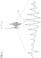
display unit 8 of the bloodpressure measuring apparatus 1 is described with reference toFIG. 7 . - As shown in
FIG. 7 , the values of the respiratory variation on the waveform of artery and the values of the mean venous pressure obtained as described above are displayed as a two-dimensional graph on thedisplay unit 8. Also, a determination criterion for determining the value of the respiratory variation on the waveform of artery and the value of the mean venous pressure is displayed as threshold lines m, n, for example. - Based on the display of the two-dimensional graph, the hemodynamics of the subject being tested is determined as follows. For example, when the obtained value of the respiratory variation on the waveform of artery and the obtained value of the mean venous pressure are a point q on the graph, the value of the respiratory variation on the waveform of artery is below the threshold line n and the value of the mean venous pressure is above the threshold line m, it is determined that circulating blood volume is excessive. Also, for example, when the obtained values are a point r, the value of the respiratory variation on the waveform of artery is above the threshold line n and the value of the mean venous pressure is below the threshold line m, it is determined that circulating blood volume is insufficient.
- Also, although not shown in
FIG. 7 , the values of the diastolic blood pressure, systolic blood pressure and mean blood pressure obtained as described above are also displayed simultaneously with the display of the two-dimensional graph on thedisplay unit 8. - According to the blood
pressure measuring apparatus 1 of the illustrative embodiment, during one-time blood pressure measurement by the oscillometric method, the parameters of the diastolic blood pressure, mean blood pressure, systolic blood pressure, respiratory variation on the waveform of artery and mean venous pressure can be obtained at once based on the cuff pressure applied from thecuff 2 to the brachial region and the pulse wave components overlapping with the cuff pressure. For this reason, it is possible to obtain the respective parameters in a non-invasive and simple manner in a series of measuring processes. Also, since all the parameters are obtained based on the cuff pressure and the pulse wave components overlapping with the cuff pressure obtained in one-time blood pressure measurement, the relativity of the parameters is very high, as compared to a configuration where the parameters are obtained based on the cuff pressure and the pulse wave components overlapping with the cuff pressure obtained by measurement of a separate measuring process or by mounting thecuff 2 to a separate region. That is, while the respiratory variation on the waveform of artery and the mean venous pressure obtained by the method of the related art are the indexes having low reliability, it is possible to correctly assess the hemodynamics of the subject being tested H based on the parameters having high relativity, in accordance with the illustrative embodiment of the present invention. - Also, since the diastolic blood pressure, mean blood pressure, systolic blood pressure are measured during the pressurization process of the cuff pressure, it is possible to shorten the time necessary to complete the measurement of the above blood pressures, as compared to a configuration where the cuff pressure is increased above the systolic blood pressure and the diastolic blood pressure, mean blood pressure, systolic blood pressure are measured during the depressurization process of the cuff pressure. Thereby, since it is possible to secure the longer time necessary for obtaining the respiratory variation on the waveform of artery and the mean venous pressure in the series of measuring processes, it is possible to obtain the parameters securely and correctly.
- Also, since the respiratory variation on the waveform of artery is obtained during the time period for which the cuff pressure is kept at a constant pressure, it is possible to clearly plot the envelope curves p connecting the peaks of the pulse wave components, so that it is possible to correctly obtain the variation components based on the respiration of the subject being tested, which are included in the pressure waveform. Also, since about 60 seconds are secured with respect to the time period for which the cuff pressure is kept at a constant pressure, it is possible to calculate the respiratory variation on the waveform of artery during the multiple respiratory periods, so that it is possible to obtain the more correct measurement result. Also, the cuff pressure is kept at the constant pressure within a range close to the diastolic blood pressure and not including the pulse wave components of the vein. Therefore, when obtaining the respiratory variation on the waveform of artery, the pulse of the vein little influences, so that it is possible to correctly extract the respiratory variation on the waveform of artery.
- In the meantime, some subjects being tested may have the low diastolic blood pressure. Therefore, when obtaining the respiratory variation on the waveform of artery, the pulse wave components of the vein may overlap with the pulse wave components of the artery and may influence the same. Regarding this, according to the illustrative embodiment, the correlation coefficients R1 between the extracted pulse wave components b1, b2, b3,··· and the representative pulse wave component a1, which is the typical pulse wave of the artery, are calculated and the pulse wave component having low correlativity (a ratio that the pulse wave component of the vein overlaps is high) is excluded to improve the reliability of the respiratory variation on the waveform of artery. In this case, the pulse wave component having low correlativity is excluded based on the correlation coefficients R1 between the extracted pulse wave components b1, b2, b3,··· obtained by one-time blood pressure measurement and the representative pulse wave component a1. Therefore, it is possible to obtain the respiratory variation on the waveform of artery by using the pulse wave components having higher relativity, as compared to a configuration where the respective blood pressures and the respiratory variation on the waveform of artery are obtained by measurements of separate measuring processes or by mounting the
cuff 2 to separate regions, for example. Thereby, it is possible to obtain the respiratory variation on the waveform of artery having high reliability, so that it is possible to assess the correct hemodynamics. - Also, since the mean venous pressure is obtained during the depressurization process of the cuff pressure, it is possible to observe the pulse wave components of the vein while gradually decreasing the pulse wave components of the arterial pressure. For this reason, it is possible to easily detect an amplitude variation in the pulse wave components of the vein, so that it is possible to correctly obtain the mean venous pressure. Also, since the cuff pressure is stepwise decreased, the electromagnetic valve less influences, as compared to a configuration where the cuff pressure is continuously decreased, so that it is possible to more correctly obtain the mean venous pressure.
- In the meantime, for some subjects being tested having the low diastolic blood pressure, even though the cuff pressure is reduced, the pulse wave components of the artery may remain without being all eliminated and thus influence the mean venous pressure. Therefore, according to the illustrative embodiment, the correlation coefficients R2 between the extracted pulse wave components c1, c2, c3, ··· and the representative pulse wave component a1, which is a typical pulse wave of the artery, are calculated and the pulse wave component having high correlativity (a ratio that the pulse wave component of the artery overlaps is high) is excluded based on the correlation coefficients R2. In this case, the pulse wave component having high correlativity is excluded based on the correlation coefficients R2 between the pulse wave components c1, c2, c3,··· obtained by one-time blood pressure measurement and the representative pulse wave component a1. Therefore, it is possible to obtain the mean venous pressure by using the pulse wave components having higher relativity, as compared to a configuration where the respective blood pressures and the mean venous pressure are obtained by measurements of separate measuring processes or by mounting the
cuff 2 to separate regions and the pulse wave component having high correlativity is excluded based on the correlation coefficients R2 of the pulse wave components extracted therefrom, for example. Thereby, it is possible to obtain the mean venous pressure less influenced by the arterial pressure and having high reliability, so that it is possible to assess the correct hemodynamics. - Also, since the respective parameters can be obtained in the non-invasive manner and the series of measuring processes are completed in a short time such as about 140 seconds, it is possible to considerably reduce the burden of the subject being tested.
- Also, since the relativity between the obtained values of the respiratory variation on the waveform of artery and the obtained values of the venous pressure is displayed as the two-dimensional graph on the
display unit 8, a medical staff who is monitoring the biological information can comprehensively determine the two parameters of the respiratory variation on the waveform of artery and the venous pressure by seeing thedisplay unit 8, thereby correctly assessing the hemodynamics of the subject being tested. Furthermore, since the threshold lines m, n, which are the criteria for determining the values of the respiratory variation on the waveform of artery and the values of the mean venous pressure, are displayed on the two-dimensional graph, the medical staff who is monitoring the biological information can easily assess the hemodynamics. - For example, when the pulse wave components of the artery overlap with the pulse wave components of the vein at the time that the value of the diastolic blood pressure is low and the mean venous pressure is obtained, the pulse wave components of the artery detected at the time that the respiratory variation on the waveform of artery is obtained are subtracted from the overlapping pulse wave components. Thereby, it is possible to calculate the correct correlation coefficients R2, thereby improving the reliability of the mean venous pressure. Likewise, when the pulse wave components of the vein overlap with the pulse wave components of the artery at the time that the value of the diastolic blood pressure is low and the respiratory variation on the waveform of artery is obtained, the pulse wave components of the artery detected upon the calculation of the mean venous pressure are subtracted after the calculation of the mean venous pressure is completed. Thereby, it is possible to calculate the correct correlation coefficients R2, thereby improving the reliability of the respiratory variation on the waveform of artery.
- Also, the reduction of the cuff pressure during the time period C for which the mean venous pressure is obtained is not limited to the stepwise reduction and the cuff pressure may be continuously reduced. Further, the cuff pressure may be stepwise or continuously increased to obtain the mean venous pressure during the pressurization process (the second process). Also, when calculating the correlation coefficient R2 of the pulse wave components at the time that the mean venous pressure is obtained, the pulse wave component of the mean blood pressure is used as the representative pulse wave component a1. However, for example, any one of the pulse wave components b1, b2, b3, ··· having the highest correlativity with the representative pulse wave component a1 may be used as the representative pulse wave component when measuring the respiratory variation on the waveform of artery. In this case, since the pulse wave components b1, b2, b3 are closer upon the measurement of the mean venous pressure in the elapsed measuring time, it is possible to increase the correctness of the correlation coefficient R2.
- Also, when measuring the mean venous pressure, a representative pulse may be determined from the pulse wave components of the artery during the process of measuring the respiratory variation on the waveform of artery, a correlativity between the representative pulse and a pulse wave component for obtaining the mean venous pressure may be obtained to determine the pulse wave component for obtaining the mean venous pressure. Further, the sequence of measuring the pulse wave components may not be the order of the arterial pressure, the respiratory variation on the waveform of artery and the mean venous pressure. For example, the pulse wave components may be measured in order of the mean venous pressure, the respiratory variation on the waveform of artery and the arterial pressure. Also, only the respiratory variation on the waveform of artery and mean venous pressure may be measured.
Claims (12)
- A blood pressure measuring apparatus (1) comprising:a cuff (2) configured to be mounted to a region of a living body in which a vein and an artery exist;a pressure control unit (3) configured to control an applied pressure applied to the region by the cuff mounted to the region;a detection unit (4) configured to detect pressure waveforms in which pulse wave components from the region overlap with the applied pressure; andan analysis unit (5) configured to obtain an arterial pressure, a respiratory variation on the waveform of artery and a venous pressure based on the pressure waveforms detected by the detection unit through one-time blood pressure measurement,wherein the analysis unit (5) is configured to obtain:the respiratory variation on the waveform of artery based on data of a first pressure waveform of the pressure waveforms in a first process, in which the applied pressure is kept at a constant pressure by the pressure control unit (3);the venous pressure based on data of a second pressure waveform of the pressure waveforms in a second process in which the applied pressure is decreased or increased by the pressure control unit; andthe arterial pressure based on data of a third pressure waveform of the pressure waveforms in a third process in which the applied pressure is decreased or increased by the pressure control unit (3), andwherein the first, second and third processes for obtaining respectively the respiratory variation, the venous pressure, and the arterial pressure are completed in about 140 seconds.
- The blood pressure measuring apparatus (1) according to claim 1, wherein the
applied pressure in the first process is equal to or lower than a diastolic blood pressure and within a range which does not include a pulse wave component of the vein in the pulse wave components. - The blood pressure measuring apparatus (1) according to claim 1 or 2, wherein
the analysis unit (5) is configured to obtain the venous pressure based on the data of the pressure waveform in the second process when a correlativity between the data of the second pressure waveform in the second process and the data of the first pressure waveform in the first process is low. - The blood pressure measuring apparatus (1) according to claim 1 or 2, wherein the analysis unit (5) is configured to obtain the venous pressure based on the data of the second pressure waveform in the second process and the data of the third pressure waveform in the third process or the data of the first pressure waveform in the first process.
- The blood pressure measuring apparatus (1) according to claim 4, wherein the analysis unit (5) is configured to obtain the venous pressure based on the data of the second pressure waveform in the second process when a correlativity between the data of the second pressure waveform in the second process and the data of the third pressure waveform in the third process or the data of the first pressure waveform in the first process is low.
- the blood pressure measuring apparatus (1) according to any of claims 1 to 5, further comrpsing: a display unit (8); and a display control unit (7) that controls the display unit (8), wherein the display control unit (7) is configured to display a value of the obtained respiratory variation on the waveform of artery and a value of the obtained venous pressure with a two-dimensional graph on the display unit (8).
- The blood pressure measuring apparatus (1) according to claim 6, wherein a determination criterion for determining the displayed value of the respiratory variation on the waveform of artery and the displayed value of the venous pressure is displayed on the two-dimensional graph.
- A blood pressure measuring method for controlling an applied pressure applied to a region of a living body in which a vein and an artery exist by a cuff mountable to the region, detecting pressure waveforms in which pulse wave components are overlapped with the applied pressure, and obtaining an arterial pressure, a respiratory variation on a waveform of artery of an arterial pressure and a venous pressure based on the detected pressure waveforms, the method comprising:obtaining the respiratory variation on the waveform of artery based on data of a first pressure waveform of the pressure waveforms in a first process, in which the applied pressure is kept at a constant pressure,obtaining the venous pressure based on data of a second pressure waveform of the pressure waveforms in a second process, in which the applied pressure is decreased or increased, and the data of the first pressure waveform, andobtaining the arterial pressure based on data of a third pressure waveform in a third process in which the applied pressure is decreased or increased,wherein the first process, the second process and the third process are performed by a one-time blood pressure measurement, andwherein the first, second and third processes for obtaining respectively the respiratory variation, the venous pressure, and the arterial pressure are completed in about 140 seconds.
- The blood pressure measuring apparatus (1) according to claim 1, wherein each of the respiratory variation, the venous pressure, and the arterial pressure is obtained for a corresponding time period (A, B, C).
- The blood pressure measuring apparatus (1) according to claim 9, wherein the time period for obtaining the respiratory variation is about 60 seconds.
- The blood pressure measuring apparatus (1) according to claim 1, wherein an interval of decreasing the applied pressure when obtaining the venous pressure is at least 6 seconds.
- The blood pressure measuring apparatus (1) according to claim 9, wherein the time period for obtaining the arterial pressure about 15 seconds.
Applications Claiming Priority (1)
| Application Number | Priority Date | Filing Date | Title |
|---|---|---|---|
| JP2014038510A JP6282887B2 (en) | 2014-02-28 | 2014-02-28 | Blood pressure measuring device and blood pressure measuring method |
Publications (2)
| Publication Number | Publication Date |
|---|---|
| EP2912996A1 EP2912996A1 (en) | 2015-09-02 |
| EP2912996B1 true EP2912996B1 (en) | 2023-03-01 |
Family
ID=52473805
Family Applications (1)
| Application Number | Title | Priority Date | Filing Date |
|---|---|---|---|
| EP15155742.8A Active EP2912996B1 (en) | 2014-02-28 | 2015-02-19 | Blood pressure measuring apparatus and method |
Country Status (4)
| Country | Link |
|---|---|
| US (1) | US11903684B2 (en) |
| EP (1) | EP2912996B1 (en) |
| JP (1) | JP6282887B2 (en) |
| CN (1) | CN104873182A (en) |
Families Citing this family (15)
| Publication number | Priority date | Publication date | Assignee | Title |
|---|---|---|---|---|
| JP2016055093A (en) * | 2014-09-12 | 2016-04-21 | セイコーエプソン株式会社 | Blood pressure measurement apparatus and blood pressure measurement method |
| JP6607728B2 (en) | 2015-08-06 | 2019-11-20 | 日本光電工業株式会社 | Venous pressure measuring device, venous pressure measuring method, and program |
| JP6577821B2 (en) * | 2015-10-19 | 2019-09-18 | 日本光電工業株式会社 | Pulse wave analyzer |
| TWI670046B (en) * | 2016-03-29 | 2019-09-01 | 豪展醫療科技股份有限公司 | Measuring device and method for measuring emotional stress index and blood pressure detecting |
| EP3427652B1 (en) | 2016-04-15 | 2021-06-09 | Omron Corporation | Biological information analysis device, system, and program |
| EP3457929B1 (en) * | 2016-05-20 | 2023-07-05 | Christian Medical College | Non-invasive system and method for measuring blood pressure variability |
| JP7187493B2 (en) * | 2017-03-02 | 2022-12-12 | アトコア メディカル ピーティーワイ リミテッド | Non-invasive brachial blood pressure measurement |
| JP6747345B2 (en) * | 2017-03-14 | 2020-08-26 | オムロンヘルスケア株式会社 | Blood pressure data processing device, blood pressure data processing method, and blood pressure data processing program |
| CN109549639A (en) * | 2017-09-26 | 2019-04-02 | 郑昕 | A kind of pulse wave pressure and blood pressure measurement device and measurement method |
| JP6988001B2 (en) * | 2018-08-30 | 2022-01-05 | オリンパス株式会社 | Recording device, image observation device, observation system, observation system control method, and observation system operation program |
| JP7269709B2 (en) | 2018-09-28 | 2023-05-09 | 日本光電工業株式会社 | Venous pressure measuring device |
| DE102020001440A1 (en) * | 2020-03-06 | 2021-09-09 | Drägerwerk AG & Co. KGaA | Ventilation device |
| EP4285815A1 (en) * | 2021-03-18 | 2023-12-06 | TERUMO Kabushiki Kaisha | Arterial pressure estimation device, arterial pressure estimation system, and arterial pressure estimation method |
| JP2022167320A (en) | 2021-04-23 | 2022-11-04 | 日本光電工業株式会社 | Pulse wave analysis device, pulse wave analysis method, and pulse wave analysis program |
| JP2022178053A (en) | 2021-05-19 | 2022-12-02 | 日本光電工業株式会社 | Circulating blood amount determination device, circulating blood amount determination program, and circulating blood amount determination method |
Family Cites Families (11)
| Publication number | Priority date | Publication date | Assignee | Title |
|---|---|---|---|---|
| US5094244A (en) * | 1989-08-25 | 1992-03-10 | Health Monitors, Inc. | Apparatus and process for determining systolic blood pressure, diastolic blood pressure, mean arterial blood pressure, pulse rate, pulse wave shape, respiratory pattern, and respiratory rate |
| JP2001309894A (en) * | 2000-05-01 | 2001-11-06 | Omron Corp | Equipment for measuring peripheral venous pressure and its method |
| US7118534B2 (en) * | 2001-09-21 | 2006-10-10 | Virginia Commonwealth University | Methods for monitoring and optimizing central venous pressure and intravascular volume |
| US6974419B1 (en) * | 2002-08-01 | 2005-12-13 | Tensys Medical, Inc. | Method and apparatus for control of non-invasive parameter measurements |
| US7524290B2 (en) * | 2005-04-29 | 2009-04-28 | The Kent Scientific Corporation | System and method of non-invasive blood pressure measurements and vascular parameter detection in small subjects |
| DE102008008840A1 (en) | 2008-02-13 | 2009-09-24 | Up Management Gmbh | Method and device for the non-invasive measurement of dynamic heart-lung interaction parameters |
| WO2010019705A2 (en) * | 2008-08-12 | 2010-02-18 | The Regents Of The University Of California | Morphological clustering and analysis of intracranial pressure pulses (mocaip) |
| US8057400B2 (en) * | 2009-05-12 | 2011-11-15 | Angiologix, Inc. | System and method of measuring changes in arterial volume of a limb segment |
| US8974491B2 (en) * | 2009-06-23 | 2015-03-10 | Infarct Reduction Technologies Inc. | Methods for adaptive limb occlusion |
| JP5694032B2 (en) * | 2011-03-30 | 2015-04-01 | 日本光電工業株式会社 | Venous pressure measuring device |
| CN103070678A (en) * | 2013-02-21 | 2013-05-01 | 沈阳恒德医疗器械研发有限公司 | Non-invasive central arterial pressure detector and detection method thereof |
-
2014
- 2014-02-28 JP JP2014038510A patent/JP6282887B2/en active Active
-
2015
- 2015-02-16 CN CN201510085085.2A patent/CN104873182A/en active Pending
- 2015-02-19 US US14/625,820 patent/US11903684B2/en active Active
- 2015-02-19 EP EP15155742.8A patent/EP2912996B1/en active Active
Also Published As
| Publication number | Publication date |
|---|---|
| JP6282887B2 (en) | 2018-02-21 |
| EP2912996A1 (en) | 2015-09-02 |
| JP2015160082A (en) | 2015-09-07 |
| US11903684B2 (en) | 2024-02-20 |
| CN104873182A (en) | 2015-09-02 |
| US20150245772A1 (en) | 2015-09-03 |
Similar Documents
| Publication | Publication Date | Title |
|---|---|---|
| EP2912996B1 (en) | Blood pressure measuring apparatus and method | |
| USRE49055E1 (en) | Venous pressure measurement apparatus | |
| US7029448B2 (en) | Electronic hemomanometer and blood pressure measuring method of electronic hemomanometer | |
| CN110913756B (en) | Method for non-invasively determining at least one blood pressure value, measuring device and system for non-invasively determining blood pressure | |
| EP3474749B1 (en) | Dynamic calibration of a blood pressure measurement device | |
| EP3210529B1 (en) | Blood pressure measurement method, blood pressure measurement device, blood pressure measurement program and computer-readable storage medium | |
| JP6200352B2 (en) | Endothelial function test device | |
| JP2020028726A (en) | Apparatus and methods for computing cardiac output of living subject via applanation tonometry | |
| JP5196323B2 (en) | Blood oxygen saturation measuring device | |
| EP3229673B1 (en) | Pulse wave analyzing apparatus | |
| EP3457929B1 (en) | Non-invasive system and method for measuring blood pressure variability | |
| KR20100126128A (en) | Blood pressure monitoring apparatus and method of low pressurization | |
| EP2844133B1 (en) | System, method and computer program for using a pulse oximetry signal to monitor blood pressure | |
| US8864678B2 (en) | Blood pressure measuring method and blood pressure manometer | |
| TWI600408B (en) | Method for estimating central aortic blood pressure and apparatus using the same | |
| KR20100126127A (en) | Blood pressure estimating apparatus and method by using variable characteristic ratio | |
| JP2006340896A (en) | Blood pressure correction method and hemodynamometer | |
| US9375150B2 (en) | Identification of pressure cuff conditions using frequency content of an oscillometric pressure signal | |
| US9211070B2 (en) | Evaluation of peripheral arterial disease in a patient using an oscillometric pressure signal obtained at a lower extremity of the patient | |
| US20150051463A1 (en) | Oximetry Signal, Pulse-Pressure Correlator | |
| EP2979629A1 (en) | Biological information measuring apparatus and biological information measuring method |
Legal Events
| Date | Code | Title | Description |
|---|---|---|---|
| PUAI | Public reference made under article 153(3) epc to a published international application that has entered the european phase |
Free format text: ORIGINAL CODE: 0009012 |
|
| AK | Designated contracting states |
Kind code of ref document: A1 Designated state(s): AL AT BE BG CH CY CZ DE DK EE ES FI FR GB GR HR HU IE IS IT LI LT LU LV MC MK MT NL NO PL PT RO RS SE SI SK SM TR |
|
| AX | Request for extension of the european patent |
Extension state: BA ME |
|
| 17P | Request for examination filed |
Effective date: 20160226 |
|
| RBV | Designated contracting states (corrected) |
Designated state(s): AL AT BE BG CH CY CZ DE DK EE ES FI FR GB GR HR HU IE IS IT LI LT LU LV MC MK MT NL NO PL PT RO RS SE SI SK SM TR |
|
| STAA | Information on the status of an ep patent application or granted ep patent |
Free format text: STATUS: EXAMINATION IS IN PROGRESS |
|
| 17Q | First examination report despatched |
Effective date: 20180704 |
|
| STAA | Information on the status of an ep patent application or granted ep patent |
Free format text: STATUS: EXAMINATION IS IN PROGRESS |
|
| GRAP | Despatch of communication of intention to grant a patent |
Free format text: ORIGINAL CODE: EPIDOSNIGR1 |
|
| STAA | Information on the status of an ep patent application or granted ep patent |
Free format text: STATUS: GRANT OF PATENT IS INTENDED |
|
| INTG | Intention to grant announced |
Effective date: 20221007 |
|
| GRAS | Grant fee paid |
Free format text: ORIGINAL CODE: EPIDOSNIGR3 |
|
| GRAA | (expected) grant |
Free format text: ORIGINAL CODE: 0009210 |
|
| STAA | Information on the status of an ep patent application or granted ep patent |
Free format text: STATUS: THE PATENT HAS BEEN GRANTED |
|
| AK | Designated contracting states |
Kind code of ref document: B1 Designated state(s): AL AT BE BG CH CY CZ DE DK EE ES FI FR GB GR HR HU IE IS IT LI LT LU LV MC MK MT NL NO PL PT RO RS SE SI SK SM TR |
|
| REG | Reference to a national code |
Ref country code: GB Ref legal event code: FG4D |
|
| REG | Reference to a national code |
Ref country code: CH Ref legal event code: EP Ref country code: AT Ref legal event code: REF Ref document number: 1550449 Country of ref document: AT Kind code of ref document: T Effective date: 20230315 |
|
| REG | Reference to a national code |
Ref country code: DE Ref legal event code: R096 Ref document number: 602015082624 Country of ref document: DE |
|
| REG | Reference to a national code |
Ref country code: IE Ref legal event code: FG4D |
|
| REG | Reference to a national code |
Ref country code: LT Ref legal event code: MG9D |
|
| REG | Reference to a national code |
Ref country code: NL Ref legal event code: MP Effective date: 20230301 |
|
| PG25 | Lapsed in a contracting state [announced via postgrant information from national office to epo] |
Ref country code: RS Free format text: LAPSE BECAUSE OF FAILURE TO SUBMIT A TRANSLATION OF THE DESCRIPTION OR TO PAY THE FEE WITHIN THE PRESCRIBED TIME-LIMIT Effective date: 20230301 Ref country code: NO Free format text: LAPSE BECAUSE OF FAILURE TO SUBMIT A TRANSLATION OF THE DESCRIPTION OR TO PAY THE FEE WITHIN THE PRESCRIBED TIME-LIMIT Effective date: 20230601 Ref country code: LV Free format text: LAPSE BECAUSE OF FAILURE TO SUBMIT A TRANSLATION OF THE DESCRIPTION OR TO PAY THE FEE WITHIN THE PRESCRIBED TIME-LIMIT Effective date: 20230301 Ref country code: LT Free format text: LAPSE BECAUSE OF FAILURE TO SUBMIT A TRANSLATION OF THE DESCRIPTION OR TO PAY THE FEE WITHIN THE PRESCRIBED TIME-LIMIT Effective date: 20230301 Ref country code: HR Free format text: LAPSE BECAUSE OF FAILURE TO SUBMIT A TRANSLATION OF THE DESCRIPTION OR TO PAY THE FEE WITHIN THE PRESCRIBED TIME-LIMIT Effective date: 20230301 Ref country code: ES Free format text: LAPSE BECAUSE OF FAILURE TO SUBMIT A TRANSLATION OF THE DESCRIPTION OR TO PAY THE FEE WITHIN THE PRESCRIBED TIME-LIMIT Effective date: 20230301 |
|
| REG | Reference to a national code |
Ref country code: AT Ref legal event code: MK05 Ref document number: 1550449 Country of ref document: AT Kind code of ref document: T Effective date: 20230301 |
|
| PG25 | Lapsed in a contracting state [announced via postgrant information from national office to epo] |
Ref country code: SE Free format text: LAPSE BECAUSE OF FAILURE TO SUBMIT A TRANSLATION OF THE DESCRIPTION OR TO PAY THE FEE WITHIN THE PRESCRIBED TIME-LIMIT Effective date: 20230301 Ref country code: PL Free format text: LAPSE BECAUSE OF FAILURE TO SUBMIT A TRANSLATION OF THE DESCRIPTION OR TO PAY THE FEE WITHIN THE PRESCRIBED TIME-LIMIT Effective date: 20230301 Ref country code: NL Free format text: LAPSE BECAUSE OF FAILURE TO SUBMIT A TRANSLATION OF THE DESCRIPTION OR TO PAY THE FEE WITHIN THE PRESCRIBED TIME-LIMIT Effective date: 20230301 Ref country code: GR Free format text: LAPSE BECAUSE OF FAILURE TO SUBMIT A TRANSLATION OF THE DESCRIPTION OR TO PAY THE FEE WITHIN THE PRESCRIBED TIME-LIMIT Effective date: 20230602 Ref country code: FI Free format text: LAPSE BECAUSE OF FAILURE TO SUBMIT A TRANSLATION OF THE DESCRIPTION OR TO PAY THE FEE WITHIN THE PRESCRIBED TIME-LIMIT Effective date: 20230301 |
|
| PG25 | Lapsed in a contracting state [announced via postgrant information from national office to epo] |
Ref country code: SM Free format text: LAPSE BECAUSE OF FAILURE TO SUBMIT A TRANSLATION OF THE DESCRIPTION OR TO PAY THE FEE WITHIN THE PRESCRIBED TIME-LIMIT Effective date: 20230301 Ref country code: RO Free format text: LAPSE BECAUSE OF FAILURE TO SUBMIT A TRANSLATION OF THE DESCRIPTION OR TO PAY THE FEE WITHIN THE PRESCRIBED TIME-LIMIT Effective date: 20230301 Ref country code: PT Free format text: LAPSE BECAUSE OF FAILURE TO SUBMIT A TRANSLATION OF THE DESCRIPTION OR TO PAY THE FEE WITHIN THE PRESCRIBED TIME-LIMIT Effective date: 20230703 Ref country code: EE Free format text: LAPSE BECAUSE OF FAILURE TO SUBMIT A TRANSLATION OF THE DESCRIPTION OR TO PAY THE FEE WITHIN THE PRESCRIBED TIME-LIMIT Effective date: 20230301 Ref country code: CZ Free format text: LAPSE BECAUSE OF FAILURE TO SUBMIT A TRANSLATION OF THE DESCRIPTION OR TO PAY THE FEE WITHIN THE PRESCRIBED TIME-LIMIT Effective date: 20230301 Ref country code: AT Free format text: LAPSE BECAUSE OF FAILURE TO SUBMIT A TRANSLATION OF THE DESCRIPTION OR TO PAY THE FEE WITHIN THE PRESCRIBED TIME-LIMIT Effective date: 20230301 |
|
| PG25 | Lapsed in a contracting state [announced via postgrant information from national office to epo] |
Ref country code: SK Free format text: LAPSE BECAUSE OF FAILURE TO SUBMIT A TRANSLATION OF THE DESCRIPTION OR TO PAY THE FEE WITHIN THE PRESCRIBED TIME-LIMIT Effective date: 20230301 Ref country code: IS Free format text: LAPSE BECAUSE OF FAILURE TO SUBMIT A TRANSLATION OF THE DESCRIPTION OR TO PAY THE FEE WITHIN THE PRESCRIBED TIME-LIMIT Effective date: 20230701 |
|
| REG | Reference to a national code |
Ref country code: DE Ref legal event code: R097 Ref document number: 602015082624 Country of ref document: DE |
|
| PLBE | No opposition filed within time limit |
Free format text: ORIGINAL CODE: 0009261 |
|
| STAA | Information on the status of an ep patent application or granted ep patent |
Free format text: STATUS: NO OPPOSITION FILED WITHIN TIME LIMIT |
|
| PG25 | Lapsed in a contracting state [announced via postgrant information from national office to epo] |
Ref country code: SI Free format text: LAPSE BECAUSE OF FAILURE TO SUBMIT A TRANSLATION OF THE DESCRIPTION OR TO PAY THE FEE WITHIN THE PRESCRIBED TIME-LIMIT Effective date: 20230301 Ref country code: DK Free format text: LAPSE BECAUSE OF FAILURE TO SUBMIT A TRANSLATION OF THE DESCRIPTION OR TO PAY THE FEE WITHIN THE PRESCRIBED TIME-LIMIT Effective date: 20230301 |
|
| 26N | No opposition filed |
Effective date: 20231204 |
|
| PGFP | Annual fee paid to national office [announced via postgrant information from national office to epo] |
Ref country code: DE Payment date: 20231228 Year of fee payment: 10 |
|
| PG25 | Lapsed in a contracting state [announced via postgrant information from national office to epo] |
Ref country code: IT Free format text: LAPSE BECAUSE OF FAILURE TO SUBMIT A TRANSLATION OF THE DESCRIPTION OR TO PAY THE FEE WITHIN THE PRESCRIBED TIME-LIMIT Effective date: 20230301 |
|
| PG25 | Lapsed in a contracting state [announced via postgrant information from national office to epo] |
Ref country code: MC Free format text: LAPSE BECAUSE OF FAILURE TO SUBMIT A TRANSLATION OF THE DESCRIPTION OR TO PAY THE FEE WITHIN THE PRESCRIBED TIME-LIMIT Effective date: 20230301 |