EP2912975A1 - Cooking element for steam cooker - Google Patents
Cooking element for steam cooker Download PDFInfo
- Publication number
- EP2912975A1 EP2912975A1 EP15161485.6A EP15161485A EP2912975A1 EP 2912975 A1 EP2912975 A1 EP 2912975A1 EP 15161485 A EP15161485 A EP 15161485A EP 2912975 A1 EP2912975 A1 EP 2912975A1
- Authority
- EP
- European Patent Office
- Prior art keywords
- side wall
- base
- tubular side
- cooking element
- element according
- Prior art date
- Legal status (The legal status is an assumption and is not a legal conclusion. Google has not performed a legal analysis and makes no representation as to the accuracy of the status listed.)
- Granted
Links
Images


Classifications
-
- A—HUMAN NECESSITIES
- A47—FURNITURE; DOMESTIC ARTICLES OR APPLIANCES; COFFEE MILLS; SPICE MILLS; SUCTION CLEANERS IN GENERAL
- A47J—KITCHEN EQUIPMENT; COFFEE MILLS; SPICE MILLS; APPARATUS FOR MAKING BEVERAGES
- A47J27/00—Cooking-vessels
- A47J27/04—Cooking-vessels for cooking food in steam; Devices for extracting fruit juice by means of steam ; Vacuum cooking vessels
-
- A—HUMAN NECESSITIES
- A47—FURNITURE; DOMESTIC ARTICLES OR APPLIANCES; COFFEE MILLS; SPICE MILLS; SUCTION CLEANERS IN GENERAL
- A47J—KITCHEN EQUIPMENT; COFFEE MILLS; SPICE MILLS; APPARATUS FOR MAKING BEVERAGES
- A47J36/00—Parts, details or accessories of cooking-vessels
- A47J36/16—Inserts
- A47J36/20—Perforated bases or perforated containers to be placed inside a cooking utensil ; Draining baskets, inserts with separation wall
Definitions
- the present invention relates to the technical field of appliances and utensils for steam cooking.
- the present invention relates more particularly to a cooking element for steam cooker.
- a cooking element is intended to be disposed above a steam generating device.
- the document WO 00 30511 discloses a steam cooker cooking element, having a tubular side wall provided with an internal shoulder adapted to receive a removable perforated bottom.
- the side wall and the perforated bottom may be made of polycarbonate.
- This plastic material has the advantages of being transparent, of being very resistant to shocks, of having sufficient mechanical strength up to a temperature of 100 ° C., and of not staining in contact with foods such as tomatoes. or carrots.
- this plastic material has a low shrinkage, is deformed little molding, is relatively dimensionally stable up to the temperature of 100 ° C and has a low price.
- this plastic has the disadvantage of poor resistance to hydrolysis.
- This plastic also has the disadvantage of containing Bisphenol A.
- the document US 5,974,953 discloses a steam cooker cooking element having a perforated bottom having a removable tubular side wall.
- the perforated bottom is advantageously made of stainless steel.
- the tubular side wall is made of transparent plastic, impact resistant.
- the lower part of the tubular side wall has an internal lower recess surrounded by an annular amount of the perforated bottom.
- the tubular side wall has an annular bearing zone surrounding the inner lower recess. Thus, only the internal lower recess is held externally by the annular amount of the bottom perforated.
- An object of the present invention is to provide a cooking element having a tubular side wall made at least partially of transparent plastic material.
- Another object of the present invention is to provide a cooking element having a tubular side wall which is not likely to stain in contact with food such as tomatoes or carrots.
- Another object of the present invention is to provide a cooking element having a tubular side wall having a sufficient mechanical strength up to the temperature of 100 ° C.
- Another object of the present invention is to provide a cooking element having a tubular side wall which is dimensionally stable up to a temperature of 100 ° C.
- Another object of the present invention is to provide a cooking element having a tubular side wall which has good resistance to hydrolysis.
- Another object of the present invention is to provide a cooking element having a tubular side wall which is free of additives such as Bisphenol A.
- a cooking element for steam cooker comprising a tubular side wall integral with an internal support member providing at least one opening for the passage of steam, the tubular side wall being made at least partially of material transparent plastic, because said transparent plastics material is plastically deformable under load flexing at a temperature of 100 ° C or less, the inner support member is at a base carrying the tubular sidewall, and said base is made of material capable of withstanding the flexion under load at a temperature 100 ° C or that the base comprises a frame connected to the tubular side wall and made of material capable of withstand bending under load at a temperature of 100 ° C.
- transparent plastics having insufficient flexural strength properties for use in a steam cooker can be used to produce a tubular sidewall working essentially in compression, materials having better bending strength properties, but not necessarily transparent , which can be used to make a base for carrying food. These arrangements allow to expand the range of plastics that can be used to make the tubular side wall of the cooking element.
- the food can be placed on an additional support carried by the internal support member, or for some embodiments, directly on the internal support member.
- an outer annular rib surrounds the tubular side wall. This arrangement contributes to reinforcing the rigidity of the tubular side wall.
- the outer annular rib can be used as a gripping member.
- the outer annular rib is derived from an upper edge of the tubular side wall.
- the outer annular rib can thus form a support for receiving another cooking element. This arrangement also facilitates cleaning.
- the base is annular and the internal support member carries a perforated bottom.
- the annular base thus defines an opening.
- the annular configuration of the base distributes the forces experienced by the support member in the base by limiting the forces on the annular side wall.
- the perforated bottom is removable relative to the annular base.
- the perforated bottom could be secured in a unmountable with the ring base.
- the perforated bottom respectively the annular base
- the internal support member is formed by an annular internal shoulder. This arrangement makes it possible to better distribute the forces on the annular base.
- the base forms a perforated bottom.
- the internal support member of the base is thus formed by the solid parts of the perforated bottom, intended to carry the food or a food support accessory.
- the tubular side wall is assembled by overmolding, crimping or clipping with the base. A particularly strong assembly is thus obtained.
- the tubular side wall has conformations inserted at least partially in the base and / or enclosing part of the base. This arrangement allows better anchoring of the tubular side wall in the base.
- the tubular side wall has internal or external protuberances supporting the base. This arrangement makes it possible to avoid excessive stress on the interface between the tubular side wall and the base when the cooking element is gripped by the tubular side wall.
- the base is assembled by locking with the tubular side wall, for example by screwing or by bayonet.
- the tubular side wall has outer protuberances inserted in grooves for retaining an inner wall of the base. This arrangement simplifies the cleaning of the cooking chamber defined by the tubular side wall and the perforated bottom.
- the tubular side wall and the base are overmolded on the frame.
- the tubular side wall is made of copolyester, such as in particular Tritan TM.
- the tubular side wall is made of SAN.
- the tubular side wall is made of PMMA.
- a steam cooker cooking element comprising a tubular side wall having a lower edge resting on a base forming a perforated bottom, the tubular side wall being made at least partially of transparent plastic material, because said transparent plastic material is plastically deformable under load bending at a temperature of less than or equal to 100 ° C, and the base externally maintains a lower portion of the tubular side wall above the lower edge.
- the lateral retention of the lower part of the tubular side wall thus obtained makes it possible to limit the deformation under load of the tubular side wall.
- an outer annular rib surrounds the tubular side wall. This arrangement contributes to reinforcing the rigidity of the tubular side wall.
- the outer annular rib can be used as a gripping member.
- the outer annular rib is derived from an upper edge of the tubular side wall.
- the outer annular rib can thus forming a support for receiving another cooking element. This arrangement also facilitates cleaning.
- the tubular side wall has an inner annular rib surrounded by the base when the tubular side wall rests on the base. This arrangement improves the rigidity of the lower part of the tubular side wall.
- the inner annular rib is derived from the lower edge of the tubular side wall. This arrangement makes it possible to increase the lower bearing surface of the tubular side wall.
- the tubular side wall rests on an annular upper bearing area of the base offset from the perforated bottom of the base. This arrangement improves the rigidity of the upper annular support zone and the perforated bottom.
- the tubular side wall is made of copolyester, such as in particular Tritan TM.
- the tubular side wall is made of SAN.
- the tubular side wall is made of PMMA.
- a cooking assembly comprising a cooking element of the aforementioned type, comprising another tubular side wall intended to carry the base of said cooking element, the other tubular side wall being made at least partially of transparent plastic material.
- plastically deformable flexural under load at a temperature less than or equal to 100 ° C the base now externally an upper portion of the other tubular side wall when the base rests on the other tubular side wall.
- the other tubular side wall has an outer annular rib surrounded by the base when the base rests on the other tubular side wall. This arrangement improves the rigidity of the upper part of the other tubular side wall.
- the outer annular rib is derived from an upper edge of the other tubular side wall. This arrangement increases the upper bearing surface of the other tubular side wall.
- the tubular side wall rests on the base above the other tubular side wall. This arrangement makes it possible to limit the deformations of the base.
- the figure 1 illustrates a first embodiment of a cooking element for steam cooker, comprising a tubular side wall 1 integral with an internal support member 2 providing at least one opening 3 provided for the passage of steam.
- the tubular side wall 1 and the internal support member 2 belong to a tubular upright 4 provided to carry a removable perforated bottom 5.
- the tubular side wall 1 has an upper edge 7 and a lower edge 8, better visible on the figure 2 .
- the tubular side wall 1 is made at least partially of transparent plastic material, and preferably, is made entirely of transparent plastic material.
- the tubular side wall 1 can in particular be made of Tritan TM (copolyester manufactured by Eastmann), SAN (Styrene acrylonitrile), or PMMA (polymethyl methacrylate), these materials having the advantage of providing good transparency, to be insensitive to staining by food, to be insensitive to hydrolysis, and to be free from Bisphenol A. Tests have shown that the use of plastics plastically deformable flexibly under load at a temperature lower than or equal to 100 ° C could be envisaged for the realization of the tubular side wall 1.
- the thickness of the tubular side wall 1 can be increased beyond 2 mm. This arrangement also makes it possible to reduce the temperature of the outer face of the tubular side wall 1.
- an outer annular rib 20 surrounds the tubular side wall 1.
- the outer annular rib 20 is exposed at room temperature, not at the temperature inside the tubular side wall. 1, which makes it possible to increase the mechanical strength of the outer annular rib 20.
- the outer annular rib 20 surrounds the upper part of the tubular side wall 1. If desired, a plurality of outer annular ribs may be used.
- the outer annular rib 20 has an annular recess 21.
- the outer annular rib 20 thus comprises an inner portion 22 extending between the tubular side wall 1 and an annular upright 23 forming the annular recess 21, and an outer portion 24 s'. extending between the annular upright 23 and an outer edge 25.
- Another cooking element or a cover can thus be arranged on the annular recess 21 or on the inner part 22.
- the tubular side wall 1 is then biased in compression. More particularly, the outer annular rib 20 is derived from the upper edge 7 of the tubular side wall 1.
- the inner portion 22 extends transversely relative to the tubular side wall 1.
- the outer portion 24 is raised.
- the internal support member 2 carries the perforated bottom 5. More particularly, the internal support member 2 is formed by an annular internal shoulder 10.
- the internal support member 2 is part of a base 6 carrying the tubular side wall 1, said base 6 being made of material capable of withstanding the bending under load at a temperature of 100 ° C.
- Base 6 is not necessarily made of transparent material, the user can observe the content of the cooking element by the tubular side wall 1.
- the base 6 may in particular be made of PBT (Polybutylene Terephthalate), or PP (polypropylene).
- the base 6 is annular. As visible on the figure 2 the base 6 has an annular body 30, a lower annular rib 31 and an upper annular rib 34. The upper annular rib 34 and the lower annular rib 31 are derived from the annular body 30. Internal tongues 33 from the annular body 30 extend towards the opening 3 of the base 6.
- the upper annular rib 34 is arranged inside the tubular side wall 1.
- the tubular side wall 1 is assembled by overmoulding with the base 6 to form the tubular upright 4 associated with the removable perforated bottom 5.
- the tubular side wall 1 has conformations 12 inserted at least partially in the base 6.
- the conformations 12 are in relief and come from the lower edge 8 of the tubular side wall 1. More particularly, the conformations 12 are lower conformations extending below the lower edge 8 of the tubular side wall 1.
- the tubular side wall 1 has internal protuberances 13 supporting the base 6 when the cooking element is raised via the tubular side wall 1. As visible on the figure 3 the internal protuberances 13 extend inwardly of the tubular side wall 1. On each side of the lower part of the tubular side wall 1, two internal protuberances 13 enclose a portion 15 of the base 6.
- tubular side wall 1 could have recessed formations 12 enclosing part of the base 6.
- the base 6 has housings 32 provided to receive the conformations 12.
- the housings 32 form passages passing through the annular body 30.
- the housings 32 are arranged around the upper annular rib 34.
- the housings 32 are arranged around the annular rib 31. As seen on the figure 3 the housings 32 enclose laterally the conformations 12.
- the lower annular rib 31 is interrupted at the level of internal tongues 33 extending towards the opening 3 of the base 6.
- the internal tongues 33 rest on the internal protuberances 13 of the tubular side wall 1.
- the internal protuberances 13 have a lower rib 14 extending the lower annular rib 31 under the inner tabs 33.
- the tubular upright 4 thus has a continuous lower annular rib.
- the upper annular rib 34 serves to stiffen the base 6.
- the lower annular rib 31 and the lower ribs 14 also contribute to stiffening the base 6.
- the annular body 30 of the base 6 carries the lower edge 8 of the tubular side wall 1.
- the internal protuberances 13 of the tubular side wall 1 carry the inner tongues 33 of the base 6. A good mechanical cohesion of the tubular upright 4 is thus obtained between the base 6 and the tubular side wall 1.
- the perforated bottom 5 may have at least one retaining member 11 provided to cooperate with the annular base 6, when the perforated bottom 5 rests on the internal support member 2. As shown in FIG. figure 1 the perforated bottom 5 has two opposing retaining members 11. Thus the perforated bottom 5 is removable relative to the annular base 6, while being integral with the annular base 6.
- the annular base 6 may have at least one retaining member provided to cooperate with the perforated bottom 5, when the perforated bottom 5 rests on the internal support member 2.
- the exemplary embodiment illustrated on the Figures 6 and 7 has a tubular side wall 1 'integral with an internal support member 2' belonging to a base 6 '.
- the tubular side wall 1 ' may be identical to the tubular side wall 1.
- the base 6' is assembled by overmoulding with the tubular side wall 1 'to form a one-piece cooking element.
- the exemplary embodiment illustrated on the Figures 6 and 7 differs from the embodiment illustrated on the Figures 1 to 5 in that the base 6 'forms a perforated bottom 5' intended to receive the food, if desired placed in a receptacle or on an accessory support.
- the perforated bottom 5 ' is the internal support member 2' providing at least one opening 3 'provided for the passage of steam.
- the perforated bottom 5 ' has a plurality of openings 3', as better visible on the figure 7 .
- the base 6 ' can in particular be made of PBT or PP.
- the exemplary embodiment illustrated on the Figures 8 and 9 has a tubular side wall 51 integral with an inner support member 52 belonging to a base 56.
- the tubular side wall 51 has a lower edge 58.
- the base 56 forms a perforated bottom 55 provided for receiving food, constituting the internal support member 52 providing at least one opening 53 provided for the passage of steam.
- the base 56 has an annular flange 59 surrounding the perforated bottom 55.
- the annular flange 59 extends around the tubular side wall 51.
- the tubular side wall 51 has an upper edge 57 and a lower edge 58.
- the exemplary embodiment illustrated on the Figures 8 and 9 differs from the embodiment illustrated on the Figures 6 and 7 in that the base 56 is locked together with the tubular side wall 51.
- the tubular side wall 51 has outer protuberances 65 inserted in retaining grooves 66 of an inner wall 67 56.
- the base 56 is locked by bayonet with the tubular side wall 51. This arrangement makes it possible to make the tubular side wall 51 integral with the internal support member 52 belonging to the base 56.
- the inner wall 67 of the base 56 encloses the lower part of the tubular side wall 51.
- An outer annular rib 70 is derived from the upper edge 57 of the tubular side wall 51.
- the outer annular rib 70 surrounds the tubular side wall 51.
- the outer annular rib 70 is extended by a raised upper edge 71.
- the exemplary embodiment illustrated on the figure 10 has a tubular side wall 51 'integral with an inner support member 52' belonging to a base 56 '.
- the tubular side wall 51 ' has a lower edge 58'.
- the exemplary embodiment illustrated on the figure 10 differs from the embodiment illustrated on the Figures 8 and 9 in that the base 56 'is annular and in that the inner support member 52' carries a perforated bottom 55 'which is removable.
- the internal support member 52 'thus provides an opening 53' provided for the passage of steam. More particularly, the internal support member 52 'is formed by an annular internal shoulder 60'.
- tubular side wall 51 ' has outer protuberances 65' inserted into retaining grooves 66 'of an inner wall 67' of the annular base 56 '.
- annular base 56 ' is bayonet-locked with the tubular side wall 51'.
- An outer annular rib 70 ' originates from the upper edge 57' of the tubular side wall 51 '.
- the outer annular rib 70 ' is extended by a post 71'.
- the base 56; 56 ' is not necessarily locked by bayonet with tubular side wall 51; 51 '.
- the perforated bottom 55 ' may have at least one retaining member provided to cooperate with the annular base 56 ', respectively with the perforated bottom 55', when the perforated bottom 55 ' rests on the internal support member 52 '.
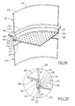
- the exemplary embodiment illustrated on the Figures 11 to 13 has a tubular side wall 101 integral with an inner support member 102 carrying a removable perforated bottom 105.
- the internal support member 102 thus belongs to an annular base 106 and provides an opening 103 provided for the passage of steam.
- the internal support member 102 is formed by an annular internal shoulder 110 of the base 106.
- the removable perforated bottom 105 has at least one retaining member 111 provided to cooperate with the base 106 when the perforated bottom 105 rests on the body internal support 102, as visible on the figure 13 .
- the exemplary embodiment illustrated on the Figures 11 to 13 differs from the embodiment illustrated on the Figures 1 to 5 in that the base 106 is assembled by crimping or clipping with the tubular side wall 101.
- the base 106 thus has a L-shaped structure with an upper branch 141 connected to an inner radial branch 142.
- the upper branch 141 encloses the lower part of the tubular side wall 101.
- the inner radial branch 142 constitutes an annular internal shoulder 110 forming the internal support member 102.
- the base 106 may for example be made of metal, in particular aluminum, if desired coated, or steel, especially stainless steel.
- the tubular side wall 101 has conformations 112 inserted at least partially into the base 106, as better visible on the figure 12 .
- the tubular side wall 101 also has outer retaining conformations 115 into which are inserted retaining ribs 116 of an inner wall of the base 106.
- the tubular side wall 101 thus has external protuberances 113 supporting the base 106.
- an outer annular rib 120 surrounds the tubular side wall 101.
- the outer annular rib 120 is derived from an upper edge 107 of the tubular side wall 101.
- the annular base 106 may have at least one retaining member provided to cooperate with the perforated bottom 105, when the perforated bottom 105 rests on the internal support member 102.
- the exemplary embodiment illustrated on the figure 14 a one-piece cooking element and differs from the embodiment illustrated in FIGS. Figures 11 to 13 in that the internal support member 102 'belongs to a base 106' forming a perforated bottom 105 'intended to receive food, if desired placed in a receptacle or on an accessory support.
- the internal support member 102 'thus provides a plurality of openings 103' provided for the passage of steam.
- the tubular side wall 101 'shown in FIG. figure 14 is identical to the tubular wall 101.
- the exemplary embodiment illustrated on the Figures 15 and 16 comprises a tubular side wall 151 secured to an internal support member 152 carrying a removable perforated bottom 155.
- the internal support member 152 thus belongs to an annular base 156.
- the internal support member 152 has an opening 153 provided for the passage of steam.
- the internal support member 152 is formed by an annular internal shoulder 160 of the base 156.
- the exemplary embodiment illustrated on the Figures 15 and 16 differs from the embodiment illustrated on the Figures 1 to 5 in that the base 156 comprises an armature 190 connected to the tubular side wall 151, the armature 190 being made of material capable of withstanding the bending under load at a temperature 100 ° C.
- the base 156 may be at least partially made of material which does not have a satisfactory resistance to flexure under load at a temperature of less than or equal to 100 ° C., for example using the same material as for the tubular side wall 151.
- the armature 190 is advantageously annular and has an L-shaped profile with an upper branch 191 connected to an inner radial branch 192.
- the armature 190 may for example be made of aluminum or steel, especially stainless steel.
- the tubular side wall 151 and the base 156 are overmolded on the frame 190 so that the tubular side wall 151 is integral with the internal support member 152 carrying the perforated bottom 155 removable.
- the perforated bottom 155 rests on the annular internal shoulder 160 made of the material used for overmolding.
- the perforated bottom 155 could rest directly on the frame 190.
- the frame 190 then forms the internal support member 152.
- an outer annular rib 170 surrounds the tubular side wall 151.
- the outer annular rib 170 is derived from an upper edge 157 of the tubular side wall 151.
- the exemplary embodiment illustrated on the figure 17 relates to a one-piece cooking element, wherein the tubular side wall 151 'is identical to the tubular wall 151.
- This embodiment differs from the embodiment shown in FIGS. Figures 15 and 16 in that the base 156 'comprises a frame 190' forming a perforated bottom 155 'intended to receive the food, if desired placed in a receptacle or on an accessory support.
- the armature 190 'thus forms the support member 152' of the base 156 '.
- the frame 190 ' has a branch upper 191 'identical to the upper branch 191 of the frame 190.
- the upper branch 191' surrounds the perforated bottom 155 'providing a plurality of openings 153' provided for the passage of steam.
- the inner support member 2, 52 ', 102, 152 is not necessarily formed by an annular internal shoulder, but could for example have discontinuous bearing areas.
- the perforated bottom 5; 105 resting on the internal support member 2; 102 could be devoid of retaining member 11; 111.
- the perforated bottom 55 '; 155, respectively the base 56 '; 156 annular could have a retainer provided to cooperate with the base 56 '; 156 annular respectively with the perforated bottom 55 '; 155, when the perforated bottom 55 '; 155 rests on the internal support member 52 '; 152.
- the base 6; 6 '; 56; 56 ' is not necessarily made of plastic and could be made at least partially of metal; the base 106; 106 '; 156; 156 'is not necessarily made of metal and could be made at least partially of plastic.
- tubular side wall 1; 1 '; 51; 51 ', 101; 101 '; 151; 151 'could comprise one or more internal and / or external ribs extending over at least a portion of the height of said tubular side wall, to stiffen said tubular side wall.
- the inner wall 67; 67 'from base 56; 56 'could encircle annularly the lower part of the tubular side wall 51; 51 '.
- the inner wall 67; 67 'from base 56; 56 ' encloses the lower part of the tubular side wall 51; 51 '.
- This arrangement makes it possible to hold the tubular lateral wall 51 laterally; 51 'and to limit the deformation under load of the tubular side wall 51; 51 '.
- the inner wall 67; 67 'from base 56; 56 ' encloses the lower part of the tubular side wall 51; 51 'in a discontinuous manner, to avoid jamming of the tubular side wall 51; 51 'inside the base 56; 56 '.
- the tubular side wall 51; 51 ' is not necessarily locked with the base 56; 56 ', the tubular side wall 51; 51 'may be devoid of external protuberances 65; 65 'and the inner wall 67; 67 'from base 56; 56 'may be devoid of retaining grooves 66; 66.
- the tubular side wall 51; 51 ' comprises at least one gripping member, formed for example by an annular flange 59, or by two opposite protuberances.
- the cooking element according to the third embodiment or modified according to the variant above thus comprises the tubular side wall 51 having a lower edge resting on the base 56 forming the perforated bottom 55.
- the tubular side wall 51 is made at least partially made of transparent plastic plastically deformable flexibly under load at a temperature of less than or equal to 100 ° C.
- the base 56 externally maintains a lower portion of the tubular side wall 51 above the lower edge of the tubular side wall 51, because the inner wall 67 of the base 56 encloses the lower portion of the tubular side wall 51.
- the exemplary embodiment illustrated on the Figures 19 and 20 also relates to a cooking element for steam cooker, having a tubular side wall 201 having a lower edge 230 resting on a base 206, forming a perforated bottom 205, wherein the tubular side wall 201 is made at least partially of deformable transparent plastic material plastically bending under load at a temperature of less than or equal to 100 ° C.
- the base 206 externally maintains a lower portion 231 of the tubular side wall 201 above the lower edge 230.
- the tubular side wall 201 has an inner annular rib 232. More particularly, the inner annular rib 232 is derived from the lower edge 230 of the tubular side wall 201. As shown in FIG. figure 20 the inner annular rib 232 is surrounded by the base 206 when the tubular side wall 201 rests on the base 206.
- An outer annular rib 220 surrounds the tubular side wall 201. More particularly, the outer annular rib 220 is derived from an upper edge 207 of the tubular side wall 201.
- the perforated bottom 205 of the base 206 has a plurality of openings 203 provided for the passage of steam.
- the perforated bottom 205 is surrounded by an upper annular support zone 240 provided to receive the lower edge 230 of the tubular side wall 201.
- the upper annular support zone 240 is connected to the perforated bottom 205 by a recess 241.
- the tubular side wall 201 rests on the upper annular support zone 240 of the base 206 offset from the perforated bottom 205 of the base 206.
- An upper post 242 surrounds the upper annular support zone 240.
- the base 206 has an annular flange 209 surrounding the perforated bottom 205. More particularly, the annular flange 209 is derived from the upper upright 242. The annular flange 209 forms a gripping member for moving the cooking element formed by the base 206 and the tubular side wall 201.
- the cooking element formed by the base 206 and the tubular side wall 201 may be associated with another cooking element, if desired of the same type, to form a staged cooking assembly.
- the Figures 19 and 20 illustrate a cooking assembly comprising a cooking element formed by the base 206 and the tubular side wall 201 as well as a another tubular side wall 251 provided to carry the base 206 of the cooking element.
- the other tubular side wall 251 is advantageously identical to the tubular side wall 201 and can be made at least partially of plastic transparent plastically deformable plastic bending under load at a temperature less than or equal to 100 ° C.
- the base 206 externally maintains an upper portion of the other tubular side wall 251 when the base 206 rests on the other tubular side wall 251.
- the base 206 has a lower leg 243 surrounding a lower bearing zone 244 provided to rest on the other tubular side wall 251.
- the tubular side wall 201 rests on the base 206 above the other tubular side wall 251.
- the base 206 is thus urged in compression between the tubular side wall 201 and the other tubular side wall 251, rather than in flexion.
- the other tubular side wall 251 has an outer annular rib 270 surrounded by the base 206 when the base 206 rests on the other tubular side wall 251.
- the outer annular rib 270 the other tubular side wall 251 is derived from an upper edge 257 of the other tubular side wall 251.
- the proposed embodiments thus make it possible to increase the temperature limit of use of plastic materials having limited mechanical properties, by better controlling the buckling under load of a tubular wall.
Abstract
L'invention concerne un élément de cuisson pour cuiseur vapeur, comportant une paroi latérale tubulaire (1) solidaire d'un organe de support interne (2) ménageant au moins une ouverture (3) prévue pour le passage de la vapeur, la paroi latérale tubulaire (1) étant réalisée au moins partiellement en matière plastique transparente. Selon l'invention, ladite matière plastique transparente est déformable plastiquement en flexion sous charge à une température inférieure ou égale à 100°C, l'organe de support interne (2) appartenant à une base (6) portant la paroi latérale tubulaire (1), ladite base (6) étant réalisée en matière apte à la tenue en flexion sous charge à une température de 100°C.The invention relates to a cooking element for a steam cooker, comprising a tubular side wall (1) integral with an internal support member (2) providing at least one opening (3) provided for the passage of steam, the side wall tubular (1) being made at least partially of transparent plastic material. According to the invention, said transparent plastics material is plastically deformable in bending under load at a temperature of less than or equal to 100.degree. C., the inner support member (2) belonging to a base (6) carrying the tubular sidewall (1). ), said base (6) being made of material capable of withstanding flexural stress under load at a temperature of 100 ° C.
Description
La présente invention concerne le domaine technique des appareils et ustensiles de cuisson à la vapeur.The present invention relates to the technical field of appliances and utensils for steam cooking.
La présente invention concerne plus particulièrement un élément de cuisson pour cuiseur vapeur. Un tel élément de cuisson est prévu pour être disposé au dessus d'un dispositif de production de vapeur.The present invention relates more particularly to a cooking element for steam cooker. Such a cooking element is intended to be disposed above a steam generating device.
Le document
Le document
Un objet de la présente invention est de proposer un élément de cuisson présentant une paroi latérale tubulaire réalisée au moins partiellement en matière plastique transparente.An object of the present invention is to provide a cooking element having a tubular side wall made at least partially of transparent plastic material.
Un autre objet de la présente invention est de proposer un élément de cuisson présentant une paroi latérale tubulaire qui ne soit pas susceptible de se tacher au contact d'aliments tels que les tomates ou les carottes.Another object of the present invention is to provide a cooking element having a tubular side wall which is not likely to stain in contact with food such as tomatoes or carrots.
Un autre objet de la présente invention est de proposer un élément de cuisson présentant une paroi latérale tubulaire présentant une résistance mécanique suffisante jusqu'à la température de 100°C.Another object of the present invention is to provide a cooking element having a tubular side wall having a sufficient mechanical strength up to the temperature of 100 ° C.
Un autre objet de la présente invention est de proposer un élément de cuisson présentant une paroi latérale tubulaire qui soit stable dimensionnellement jusqu'à la température de 100°C.Another object of the present invention is to provide a cooking element having a tubular side wall which is dimensionally stable up to a temperature of 100 ° C.
Un autre objet de la présente invention est de proposer un élément de cuisson présentant une paroi latérale tubulaire qui présente une bonne résistance à l'hydrolyse.Another object of the present invention is to provide a cooking element having a tubular side wall which has good resistance to hydrolysis.
Un autre objet de la présente invention est de proposer un élément de cuisson présentant une paroi latérale tubulaire qui soit exempte d'additifs tels que le Bisphénol A.Another object of the present invention is to provide a cooking element having a tubular side wall which is free of additives such as Bisphenol A.
Ces objets sont atteints avec un élément de cuisson pour cuiseur vapeur, comportant une paroi latérale tubulaire solidaire d'un organe de support interne ménageant au moins une ouverture prévue pour le passage de la vapeur, la paroi latérale tubulaire étant réalisée au moins partiellement en matière plastique transparente, du fait que ladite matière plastique transparente est déformable plastiquement en flexion sous charge à une température inférieure ou égale à 100°C, que l'organe de support interne appartient à une base portant la paroi latérale tubulaire, et que ladite base est réalisée en matière apte à la tenue en flexion sous charge à une température de 100°C ou que la base comporte une armature reliée à la paroi latérale tubulaire et réalisée en matière apte à la tenue en flexion sous charge à une température de 100°C. Ainsi des matières plastiques transparentes présentant des propriétés mécaniques de tenue en flexion insuffisantes pour une utilisation dans un cuiseur vapeur peuvent être utilisées pour réaliser une paroi latérale tubulaire travaillant essentiellement en compression, des matières présentant de meilleures propriétés de tenue en flexion, mais non nécessairement transparentes, pouvant être utilisées pour réaliser une base prévue pour porter les aliments. Ces dispositions permettent d'élargir la gamme des matières plastiques susceptibles d'être utilisées pour réaliser la paroi latérale tubulaire de l'élément de cuisson. Les aliments peuvent être placés sur un support additionnel porté par l'organe de support interne, ou pour certains modes de réalisation, directement sur l'organe de support interne.These objects are achieved with a cooking element for steam cooker, comprising a tubular side wall integral with an internal support member providing at least one opening for the passage of steam, the tubular side wall being made at least partially of material transparent plastic, because said transparent plastics material is plastically deformable under load flexing at a temperature of 100 ° C or less, the inner support member is at a base carrying the tubular sidewall, and said base is made of material capable of withstanding the flexion under load at a temperature 100 ° C or that the base comprises a frame connected to the tubular side wall and made of material capable of withstand bending under load at a temperature of 100 ° C. Thus transparent plastics having insufficient flexural strength properties for use in a steam cooker can be used to produce a tubular sidewall working essentially in compression, materials having better bending strength properties, but not necessarily transparent , which can be used to make a base for carrying food. These arrangements allow to expand the range of plastics that can be used to make the tubular side wall of the cooking element. The food can be placed on an additional support carried by the internal support member, or for some embodiments, directly on the internal support member.
Avantageusement, une nervure annulaire extérieure entoure la paroi latérale tubulaire. Cette disposition contribue à renforcer la rigidité de la paroi latérale tubulaire. La nervure annulaire extérieure peut être utilisée comme organe de préhension.Advantageously, an outer annular rib surrounds the tubular side wall. This arrangement contributes to reinforcing the rigidity of the tubular side wall. The outer annular rib can be used as a gripping member.
Avantageusement alors, la nervure annulaire extérieure est issue d'un bord supérieur de la paroi latérale tubulaire. La nervure annulaire extérieure peut ainsi former un support pour recevoir un autre élément de cuisson. Cette disposition permet également de faciliter le nettoyage.Advantageously then, the outer annular rib is derived from an upper edge of the tubular side wall. The outer annular rib can thus form a support for receiving another cooking element. This arrangement also facilitates cleaning.
Selon une forme de réalisation, la base est annulaire et l'organe de support interne porte un fond perforé. La base annulaire définit ainsi une ouverture. La configuration annulaire de la base permet de répartir les efforts subis par l'organe de support dans la base en limitant les efforts sur la paroi latérale annulaire.According to one embodiment, the base is annular and the internal support member carries a perforated bottom. The annular base thus defines an opening. The annular configuration of the base distributes the forces experienced by the support member in the base by limiting the forces on the annular side wall.
Avantageusement alors, le fond perforé est amovible par rapport à la base annulaire. En alternative, le fond perforé pourrait être solidarisé de manière indémontable avec la base annulaire.Advantageously then, the perforated bottom is removable relative to the annular base. Alternatively, the perforated bottom could be secured in a unmountable with the ring base.
Avantageusement alors, le fond perforé, respectivement la base annulaire, présente un organe de retenue prévu pour coopérer avec la base annulaire, respectivement avec le fond perforé, lorsque le fond perforé repose sur l'organe de support interne. Ces dispositions permettent de solidariser de manière amovible le fond perforé et la base annulaire.Advantageously then, the perforated bottom, respectively the annular base, has a retaining member provided to cooperate with the annular base, respectively with the perforated bottom, when the perforated bottom rests on the internal support member. These arrangements make it possible to removably fasten the perforated bottom and the annular base.
Avantageusement encore, l'organe de support interne est formé par un épaulement interne annulaire. Cette disposition permet de mieux répartir les efforts sur la base annulaire.Advantageously, the internal support member is formed by an annular internal shoulder. This arrangement makes it possible to better distribute the forces on the annular base.
Selon une autre forme de réalisation, la base forme un fond perforé. L'organe de support interne de la base est ainsi formé par les parties pleines du fond perforé, prévus pour porter les aliments ou un accessoire de support d'aliments.According to another embodiment, the base forms a perforated bottom. The internal support member of the base is thus formed by the solid parts of the perforated bottom, intended to carry the food or a food support accessory.
Selon une forme d'assemblage, la paroi latérale tubulaire est assemblée par surmoulage, sertissage ou clipsage avec la base. Un assemblage particulièrement solide est ainsi obtenu.According to one form of assembly, the tubular side wall is assembled by overmolding, crimping or clipping with the base. A particularly strong assembly is thus obtained.
Avantageusement alors, la paroi latérale tubulaire présente des conformations insérées au moins partiellement dans la base et/ou enserrant une partie de la base. Cette disposition permet un meilleur ancrage de la paroi latérale tubulaire dans la base.Advantageously then, the tubular side wall has conformations inserted at least partially in the base and / or enclosing part of the base. This arrangement allows better anchoring of the tubular side wall in the base.
Avantageusement encore, la paroi latérale tubulaire comporte des protubérances internes ou externes supportant la base. Cette disposition permet d'éviter de solliciter de manière excessive l'interface entre la paroi latérale tubulaire et la base lorsque l'élément de cuisson est saisi par la paroi latérale tubulaire.Advantageously, the tubular side wall has internal or external protuberances supporting the base. This arrangement makes it possible to avoid excessive stress on the interface between the tubular side wall and the base when the cooking element is gripped by the tubular side wall.
Selon une autre forme d'assemblage, la base est assemblée par verrouillage avec la paroi latérale tubulaire, par exemple par vissage ou par baïonnette. Avantageusement alors, la paroi latérale tubulaire présente des protubérances extérieures insérées dans des rainures de retenue d'une paroi interne de la base. Cette disposition permet de simplifier le nettoyage de la chambre de cuisson définie par la paroi latérale tubulaire et le fond perforé.According to another form of assembly, the base is assembled by locking with the tubular side wall, for example by screwing or by bayonet. Advantageously then, the tubular side wall has outer protuberances inserted in grooves for retaining an inner wall of the base. This arrangement simplifies the cleaning of the cooking chamber defined by the tubular side wall and the perforated bottom.
Selon une autre forme d'assemblage, la paroi latérale tubulaire et la base sont surmoulées sur l'armature.According to another form of assembly, the tubular side wall and the base are overmolded on the frame.
Selon un mode de réalisation, la paroi latérale tubulaire est réalisée en copolyester, tel que notamment le Tritan™.According to one embodiment, the tubular side wall is made of copolyester, such as in particular Tritan ™.
Selon un autre mode de réalisation, la paroi latérale tubulaire est réalisée en SAN.According to another embodiment, the tubular side wall is made of SAN.
Selon encore un autre mode de réalisation, la paroi latérale tubulaire est réalisée en PMMA.According to yet another embodiment, the tubular side wall is made of PMMA.
Ces objets sont atteints également avec un élément de cuisson pour cuiseur vapeur, comportant une paroi latérale tubulaire présentant un bord inférieur reposant sur une base formant un fond perforé, la paroi latérale tubulaire étant réalisée au moins partiellement en matière plastique transparente, du fait que ladite matière plastique transparente est déformable plastiquement en flexion sous charge à une température inférieure ou égale à 100°C, et que la base maintient extérieurement une partie inférieure de la paroi latérale tubulaire au dessus du bord inférieur. Le maintien latéral de la partie inférieure de la paroi latérale tubulaire ainsi obtenu permet de limiter la déformation sous charge de la paroi latérale tubulaire.These objects are also achieved with a steam cooker cooking element, comprising a tubular side wall having a lower edge resting on a base forming a perforated bottom, the tubular side wall being made at least partially of transparent plastic material, because said transparent plastic material is plastically deformable under load bending at a temperature of less than or equal to 100 ° C, and the base externally maintains a lower portion of the tubular side wall above the lower edge. The lateral retention of the lower part of the tubular side wall thus obtained makes it possible to limit the deformation under load of the tubular side wall.
Avantageusement, une nervure annulaire extérieure entoure la paroi latérale tubulaire. Cette disposition contribue à renforcer la rigidité de la paroi latérale tubulaire. La nervure annulaire extérieure peut être utilisée comme organe de préhension.Advantageously, an outer annular rib surrounds the tubular side wall. This arrangement contributes to reinforcing the rigidity of the tubular side wall. The outer annular rib can be used as a gripping member.
Avantageusement alors, la nervure annulaire extérieure est issue d'un bord supérieur de la paroi latérale tubulaire. La nervure annulaire extérieure peut ainsi former un support pour recevoir un autre élément de cuisson. Cette disposition permet également de faciliter le nettoyage.Advantageously then, the outer annular rib is derived from an upper edge of the tubular side wall. The outer annular rib can thus forming a support for receiving another cooking element. This arrangement also facilitates cleaning.
Avantageusement encore, la paroi latérale tubulaire présente une nervure annulaire intérieure entourée par la base lorsque la paroi latérale tubulaire repose sur la base. Cette disposition permet d'améliorer la rigidité de la partie inférieure de la paroi latérale tubulaire.Advantageously, the tubular side wall has an inner annular rib surrounded by the base when the tubular side wall rests on the base. This arrangement improves the rigidity of the lower part of the tubular side wall.
Avantageusement alors, la nervure annulaire intérieure est issue du bord inférieur de la paroi latérale tubulaire. Cette disposition permet d'augmenter la surface d'appui inférieure de la paroi latérale tubulaire.Advantageously then, the inner annular rib is derived from the lower edge of the tubular side wall. This arrangement makes it possible to increase the lower bearing surface of the tubular side wall.
Avantageusement encore, la paroi latérale tubulaire repose sur une zone annulaire supérieure d'appui de la base décalée par rapport au fond perforé de la base. Cette disposition permet d'améliorer la rigidité de la zone annulaire supérieure d'appui et du fond perforé.Advantageously, the tubular side wall rests on an annular upper bearing area of the base offset from the perforated bottom of the base. This arrangement improves the rigidity of the upper annular support zone and the perforated bottom.
Selon un mode de réalisation, la paroi latérale tubulaire est réalisée en copolyester, tel que notamment le Tritan™.According to one embodiment, the tubular side wall is made of copolyester, such as in particular Tritan ™.
Selon un autre mode de réalisation, la paroi latérale tubulaire est réalisée en SAN.According to another embodiment, the tubular side wall is made of SAN.
Selon encore un autre mode de réalisation, la paroi latérale tubulaire est réalisée en PMMA.According to yet another embodiment, the tubular side wall is made of PMMA.
Ces objets sont atteints également avec un ensemble de cuisson comportant un élément de cuisson du type précité, comportant une autre paroi latérale tubulaire prévue pour porter la base dudit élément de cuisson, l'autre paroi latérale tubulaire étant réalisée au moins partiellement en matière plastique transparente déformable plastiquement en flexion sous charge à une température inférieure ou égale à 100°C, la base maintenant extérieurement une partie supérieure de l'autre paroi latérale tubulaire lorsque la base repose sur l'autre paroi latérale tubulaire. Cette disposition permet de réaliser un cuiseur vapeur étagé en limitant les risques de déformation de l'autre paroi latérale tubulaire.These objects are also achieved with a cooking assembly comprising a cooking element of the aforementioned type, comprising another tubular side wall intended to carry the base of said cooking element, the other tubular side wall being made at least partially of transparent plastic material. plastically deformable flexural under load at a temperature less than or equal to 100 ° C, the base now externally an upper portion of the other tubular side wall when the base rests on the other tubular side wall. This arrangement makes it possible to produce a stepped steam cooker by limiting the risk of deformation of the other wall lateral tubular.
Avantageusement alors, l'autre paroi latérale tubulaire présente une nervure annulaire extérieure entourée par la base lorsque la base repose sur l'autre paroi latérale tubulaire. Cette disposition permet d'améliorer la rigidité de la partie supérieure de l'autre paroi latérale tubulaire.Advantageously then, the other tubular side wall has an outer annular rib surrounded by the base when the base rests on the other tubular side wall. This arrangement improves the rigidity of the upper part of the other tubular side wall.
Avantageusement alors, la nervure annulaire extérieure est issue d'un bord supérieur de l'autre paroi latérale tubulaire. Cette disposition permet d'augmenter la surface d'appui supérieure de l'autre paroi latérale tubulaire.Advantageously then, the outer annular rib is derived from an upper edge of the other tubular side wall. This arrangement increases the upper bearing surface of the other tubular side wall.
Avantageusement encore, la paroi latérale tubulaire repose sur la base au dessus de l'autre paroi latérale tubulaire. Cette disposition permet de limiter les déformations de la base.Advantageously, the tubular side wall rests on the base above the other tubular side wall. This arrangement makes it possible to limit the deformations of the base.
L'invention sera mieux comprise à l'étude de neuf exemples de réalisation, pris à titre nullement limitatifs, illustrés dans les figures annexées, dans lesquelles :
- la
figure 1 est une vue en perspective d'un premier exemple de réalisation d'un élément de cuisson selon l'invention, comportant un montant tubulaire et un fond amovible, - la
figure 2 est une vue partielle en perspective retournée et en coupe du montant tubulaire illustré sur lafigure 1 , - la
figure 3 est une vue en perspective de la paroi latérale tubulaire du montant tubulaire illustré sur lesfigures 1 et 2 , réalisée en un premier matériau, - la
figure 4 est une vue en perspective de la base du montant tubulaire illustré sur lesfigures 1 et 2 , réalisée en un deuxième matériau, - la
figure 5 est une vue en perspective retournée de la base illustrée sur lafigure 4 , - la
figure 6 est une vue en perspective assemblée d'un deuxième exemple de réalisation d'un élément de cuisson selon l'invention, comportant un fond perforé lié au montant tubulaire, - la
figure 7 est une vue en perspective de la base de l'élément de cuisson selon l'invention illustré sur lafigure 6 , - la
figure 8 est une vue en perspective assemblée d'un troisième exemple de réalisation d'un élément de cuisson selon l'invention, comportant un fond perforé lié au montant tubulaire, - la
figure 9 est une vue en perspective assemblée et en coupe du troisième exemple de réalisation d'un élément de cuisson selon l'invention illustré sur lafigure 8 , - la
figure 10 est une vue en perspective en éclaté d'un quatrième exemple de réalisation d'un élément de cuisson selon l'invention, comportant un montant tubulaire et un fond amovible, - la
figure 11 est une vue partielle en perspective et en éclaté d'un cinquième exemple de réalisation d'un élément de cuisson selon l'invention, comportant un montant tubulaire et un fond amovible, - la
figure 12 est une vue partielle en coupe de la partie inférieure assemblée de l'élément de cuisson illustré sur lafigure 11 , - la
figure 13 est une vue partielle en coupe de l'élément de cuisson illustré sur lafigure 11 , - la
figure 14 est une vue partielle en coupe d'un sixième exemple de réalisation d'un élément de cuisson selon l'invention, comportant un fond perforé lié à un montant tubulaire, - la
figure 15 est une vue partielle en coupe d'un septième exemple de réalisation d'un élément de cuisson selon l'invention, comportant un montant tubulaire et un fond amovible, - la
figure 16 est une vue en perspective d'une armature de l'élément de cuisson illustré sur lafigure 15 , - la
figure 17 est une vue partielle en coupe d'un huitième exemple de réalisation d'un élément de cuisson selon l'invention, comportant un fond perforé lié à un montant tubulaire, - la
figure 18 est une vue en perspective d'une armature de l'élément de cuisson illustré sur lafigure 17 , - la
figure 19 est une vue partielle en perspective et en éclaté d'un neuvième exemple de réalisation d'un élément de cuisson selon l'invention, comportant un montant tubulaire et un fond amovible, complété d'un autre montant tubulaire appartenant à un ensemble de cuisson, - la
figure 20 est une vue partielle en coupe montrant l'assemblage de l'élément de cuisson et de l'autre montant tubulaire illustrés sur lafigure 19 .
- the
figure 1 is a perspective view of a first embodiment of a cooking element according to the invention, comprising a tubular upright and a removable bottom, - the
figure 2 is a partial perspective view in cross-sectional view of the tubular upright illustrated in FIG.figure 1 , - the
figure 3 is a perspective view of the tubular side wall of the tubular upright illustrated in FIGS.figures 1 and2 made of a first material, - the
figure 4 is a perspective view of the base of the tubular post illustrated on thefigures 1 and2 made of a second material, - the
figure 5 is an upside down perspective view of the base shown on thefigure 4 , - the
figure 6 is an assembled perspective view of a second embodiment of a cooking element according to the invention, comprising a perforated bottom connected to the tubular upright, - the
figure 7 is a perspective view of the base of the cooking element according to the invention illustrated on thefigure 6 , - the
figure 8 is an assembled perspective view of a third embodiment of a cooking element according to the invention, comprising a perforated bottom connected to the tubular upright, - the
figure 9 is an assembled and sectional perspective view of the third embodiment of a cooking element according to the invention illustrated in FIG.figure 8 , - the
figure 10 is an exploded perspective view of a fourth embodiment of a cooking element according to the invention, comprising a tubular upright and a removable bottom, - the
figure 11 is a partial perspective and exploded view of a fifth embodiment of a cooking element according to the invention, comprising a tubular upright and a removable bottom, - the
figure 12 is a partial sectional view of the assembled lower portion of the cooking element shown in FIG.figure 11 , - the
figure 13 is a partial sectional view of the cooking element illustrated on thefigure 11 , - the
figure 14 is a partial sectional view of a sixth embodiment of a cooking element according to the invention, comprising a perforated bottom connected to a tubular upright, - the
figure 15 is a partial sectional view of a seventh embodiment of a cooking element according to the invention, comprising a tubular upright and a removable bottom, - the
figure 16 is a perspective view of a frame of the cooking element illustrated on thefigure 15 , - the
figure 17 is a partial sectional view of an eighth embodiment of a cooking element according to the invention, comprising a perforated bottom connected to a tubular upright, - the
figure 18 is a perspective view of a frame of the cooking element illustrated on thefigure 17 , - the
figure 19 is a partial perspective and exploded view of a ninth embodiment of a cooking element according to the invention, comprising a tubular upright and a removable bottom, completed with another tubular upright belonging to a cooking assembly, - the
figure 20 is a partial sectional view showing the assembly of the cooking element and the other tubular upright illustrated in FIG.figure 19 .
La
La paroi latérale tubulaire 1 et l'organe de support interne 2 appartiennent à un un montant tubulaire 4 prévu pour porter un fond perforé 5 amovible.The
La paroi latérale tubulaire 1 présente un bord supérieur 7 et un bord inférieur 8, mieux visibles sur la
La paroi latérale tubulaire 1 est réalisée au moins partiellement en matière plastique transparente, et de préférence, est réalisée entièrement en matière plastique transparente.The
La paroi latérale tubulaire 1 peut notamment être réalisée en Tritan™ (copolyester fabriqué par la société Eastmann), en SAN (Styrène acrylonitrile), ou en PMMA (Polyméthacrylate de méthyle), ces matières présentant l'avantage d'offrir une bonne transparence, d'être peu sensibles au tachage par les aliments, d'être peu sensibles à l'hydrolyse, et d'être exemptes de Bisphénol A. Des essais ont en effet montré que l'utilisation de matières plastiques transparentes déformables plastiquement en flexion sous charge à une température inférieure ou égale à 100°C pouvait être envisagée pour la réalisation de la paroi latérale tubulaire 1.The
Pour améliorer la tenue mécanique de la paroi latérale tubulaire 1, l'épaisseur de la paroi latérale tubulaire 1 peut être augmentée au-delà de 2 mm. Cette disposition permet également de réduire la température de la face extérieure de la la paroi latérale tubulaire 1.To improve the mechanical strength of the
Pour limiter la déformation de la paroi latérale tubulaire 1, une nervure annulaire extérieure 20 entoure la paroi latérale tubulaire 1. La nervure annulaire extérieure 20 est exposée à la température ambiante, et non à la température régnant à l'intérieur de la paroi latérale tubulaire 1, ce qui permet d'augmenter la résistance mécanique de la nervure annulaire extérieure 20.To limit the deformation of the
Avantageusement, la nervure annulaire extérieure 20 entoure la partie supérieure de la paroi latérale tubulaire 1. Si désiré, plusieurs nervures annulaires extérieures peuvent être utilisées.Advantageously, the outer
Tel que représenté sur la
L'organe de support interne 2 porte le fond perforé 5. Plus particulièrement, l'organe de support interne 2 est formé par un épaulement interne annulaire 10.The
Pour éviter une sollicitation mécanique trop importante en flexion de la paroi latérale tubulaire 1, l'organe de support interne 2 appartient à une base 6 portant la paroi latérale tubulaire 1, ladite base 6 étant réalisée en matière apte à la tenue en flexion sous charge à une température de 100°C. La base 6 n'est pas nécessairement réalisée en matériau transparent, l'utilisateur pouvant observer le contenu de l'élément de cuisson par la paroi latérale tubulaire 1. La base 6 peut notamment être réalisée en PBT (Polybutylène Téréphthalate), ou encore en PP (Polypropylène).To avoid excessive mechanical stress in bending of the
Dans l'exemple de réalisation illustré sur les
Tel que visible sur la
La paroi latérale tubulaire 1 est assemblée par surmoulage avec la base 6 pour former le montant tubulaire 4 associé au fond perforé 5 amovible. A cet effet, tel que visible sur la
Par ailleurs, tel que visible sur la
A titre de variante, la paroi latérale tubulaire 1 pourrait présenter des conformations 12 en creux enserrant une partie de la base 6.As a variant, the
Tel que visible sur les
La nervure annulaire inférieure 31 est interrompue au niveau de languettes internes 33 s'étendant vers l'ouverture 3 de la base 6. Les languettes internes 33 reposent sur les protubérances internes 13 de la paroi latérale tubulaire 1. Tel que visible sur la
La nervure annulaire supérieure 34 permet de rigidifier la base 6. La nervure annulaire inférieure 31 et les nervures inférieures 14 contribuent également à rigidifier la base 6. Le corps annulaire 30 de la base 6 porte le bord inférieur 8 de la paroi latérale tubulaire 1. Les protubérances internes 13 de la paroi latérale tubulaire 1 portent les languettes internes 33 de la base 6. Une bonne cohésion mécanique du montant tubulaire 4 est ainsi obtenue entre la base 6 et la paroi latérale tubulaire 1.The upper
Si désiré, le fond perforé 5 peut présenter au moins un organe de retenue 11 prévu pour coopérer avec la base 6 annulaire, lorsque le fond perforé 5 repose sur l'organe de support interne 2. Tel que représenté sur la
A titre de variante, non représentée aux figures, la base 6 annulaire peut présenter au moins un organe de retenue prévu pour coopérer avec le fond perforé 5, lorsque le fond perforé 5 repose sur l'organe de support interne 2. L'exemple de réalisation illustré sur les
L'exemple de réalisation illustré sur les
Ainsi le fond perforé 5' constitue l'organe de support interne 2' ménageant au moins une ouverture 3' prévue pour le passage de la vapeur. De préférence le fond perforé 5' présente une pluralité d'ouvertures 3', tel que mieux visible sur la
L'exemple de réalisation illustré sur les
La base 56 forme un fond perforé 55 prévu pour recevoir les aliments, constituant l'organe de support interne 52 ménageant au moins une ouverture 53 prévue pour le passage de la vapeur. La base 56 présente une collerette annulaire 59 entourant le fond perforé 55. La collerette annulaire 59 s'étend autour de la paroi latérale tubulaire 51.The base 56 forms a perforated bottom 55 provided for receiving food, constituting the
La paroi latérale tubulaire 51 présente un bord supérieur 57 et un bord inférieur 58.The
L'exemple de réalisation illustré sur les
Plus particulièrement, la paroi latérale tubulaire 51 présente des protubérances extérieures 65 insérées dans des rainures de retenue 66 d'une paroi interne 67 de la base 56. Tel que représenté sur les
Une nervure annulaire extérieure 70 est issue du bord supérieur 57 de la paroi latérale tubulaire 51. La nervure annulaire extérieure 70 entoure la paroi latérale tubulaire 51. La nervure annulaire extérieure 70 est prolongée par un bord supérieur relevé 71.An outer
L'exemple de réalisation illustré sur la
L'exemple de réalisation illustré sur la
Plus particulièrement, la paroi latérale tubulaire 51' présente des protubérances extérieures 65' insérées dans des rainures de retenue 66' d'une paroi interne 67' de la base 56' annulaire. Tel que représenté sur la
Une nervure annulaire extérieure 70' est issue du bord supérieur 57' de la paroi latérale tubulaire 51'. La nervure annulaire extérieure 70' est prolongée par un montant 71'. Un bord extérieur 72' entoure la partie supérieure du montant 71'.An outer annular rib 70 'originates from the upper edge 57' of the tubular side wall 51 '. The outer annular rib 70 'is extended by a post 71'. An outer edge 72 'surrounds the upper portion of the post 71'.
A titre de variante, la base 56 ; 56' n'est pas nécessairement verrouillée par baïonnette avec la paroi latérale tubulaire 51 ; 51'. En alternative, la base 56 ; 56' pourrait notamment être verrouillée par vissage avec la paroi latérale tubulaire 51 ; 51'. '.Alternatively, the
A titre de variante, le fond perforé 55', respectivement la base 56' annulaire, peut présenter au moins un organe de retenue prévu pour coopérer avec la base 56' annulaire, respectivement avec le fond perforé 55', lorsque le fond perforé 55' repose sur l'organe de support interne 52'.Alternatively, the perforated bottom 55 ', respectively the annular base 56', may have at least one retaining member provided to cooperate with the annular base 56 ', respectively with the perforated bottom 55', when the perforated bottom 55 ' rests on the internal support member 52 '.
L'exemple de réalisation illustré sur les
L'exemple de réalisation illustré sur les
Plus particulièrement, la paroi latérale tubulaire 101 présente des conformations 112 insérées au moins partiellement dans la base 106, tel que mieux visible sur la
Pour rigidifier la partie haute de la paroi latérale tubulaire 101, une nervure annulaire extérieure 120 entoure la paroi latérale tubulaire 101. La nervure annulaire extérieure 120 est issue d'un bord supérieur 107 de la paroi latérale tubulaire 101.To stiffen the upper part of the
A titre de variante, non représentée aux figures, la base 106 annulaire peut présenter au moins un organe de retenue prévu pour coopérer avec le fond perforé 105, lorsque le fond perforé 105 repose sur l'organe de support interne 102.Alternatively, not shown in the figures, the
L'exemple de réalisation illustré sur la
L'exemple de réalisation illustré sur les
L'exemple de réalisation illustré sur les
Tel que mieux visible sur la
Tel que représenté sur la
A titre de variante, le fond perforé 155 pourrait reposer directement sur l'armature 190. L'armature 190 forme alors l'organe de support interne 152.Alternatively, the
Pour rigidifier la partie haute de la paroi latérale tubulaire 151, une nervure annulaire extérieure 170 entoure la paroi latérale tubulaire 151. La nervure annulaire extérieure 170 est issue d'un bord supérieur 157 de la paroi latérale tubulaire 151.To stiffen the upper part of the
L'exemple de réalisation illustré sur la
Tel que mieux visible sur la
A titre de variante, l'organe de support interne 2, 52', 102, 152 n'est pas nécessairement formé par un épaulement interne annulaire, mais pourrait par exemple présenter des zones d'appui discontinues.Alternatively, the
A titre de variante, le fond perforé 5 ; 105 reposant sur l'organe de support interne 2 ; 102 pourrait être dépourvu d'organe de retenue 11 ; 111.Alternatively, the
A titre de variante, le fond perforé 55' ; 155, respectivement la base 56' ; 156 annulaire pourrait présenter un organe de retenue prévu pour coopérer avec la base 56' ; 156 annulaire, respectivement avec le fond perforé 55' ; 155, lorsque le fond perforé 55' ; 155 repose sur l'organe de support interne 52' ; 152.Alternatively, the perforated bottom 55 '; 155, respectively the base 56 '; 156 annular could have a retainer provided to cooperate with the base 56 '; 156 annular respectively with the perforated bottom 55 '; 155, when the perforated bottom 55 '; 155 rests on the internal support member 52 '; 152.
A titre de variante, la base 6 ; 6' ; 56 ; 56' n'est pas nécessairement réalisée en matière plastique et pourrait être réalisée au moins partiellement en métal ; la base 106; 106' ; 156; 156' n'est pas nécessairement réalisée en métal et pourrait être réalisée au moins partiellement en matière plastique.Alternatively, the
A titre de variante, la paroi latérale tubulaire 1 ; 1' ; 51 ; 51', 101; 101'; 151; 151' pourrait comporter une ou plusieurs nervures internes et/ou externes s'étendant sur au moins une partie de la hauteur de ladite paroi latérale tubulaire, pour rigidifier ladite paroi latérale tubulaire.Alternatively, the
A titre de variante, la paroi interne 67 ; 67' de la base 56 ; 56' pourrait enserrer annulairement la partie inférieure de la paroi latérale tubulaire 51 ; 51'.Alternatively, the
Selon un autre aspect de l'invention concernant un élément de cuisson pour cuiseur vapeur comportant une paroi latérale tubulaire 51 ; 51' reposant sur une base 56 ; 56', la paroi interne 67 ; 67' de la base 56 ; 56' enserre la partie inférieure de la paroi latérale tubulaire 51 ; 51'. Cette disposition permet de maintenir latéralement la paroi latérale tubulaire 51 ; 51' et de limiter la déformation sous charge de la paroi latérale tubulaire 51 ; 51'. De préférence, la paroi interne 67 ; 67' de la base 56 ; 56' enserre la partie inférieure de la paroi latérale tubulaire 51 ; 51' de manière discontinue, afin d'éviter le coincement de la paroi latérale tubulaire 51 ; 51' à l'intérieur de la base 56 ; 56'. Plus particulièrement, la paroi interne 67 ; 67' de la base 56 ; 56' peut enserrer la partie inférieure de la paroi latérale tubulaire 51 ; 51' au niveau des protubérances extérieures 65 ; 65' et/ou entre les protubérances extérieures 65 ; 65'.According to another aspect of the invention relating to a steam cooker cooking element having a
A titre de variante, la paroi latérale tubulaire 51 ; 51' n'est pas nécessairement verrouillée avec la base 56 ; 56', la paroi latérale tubulaire 51 ; 51' peut être dépourvue de protubérances extérieures 65 ; 65' et la paroi interne 67 ; 67' de la base 56 ; 56' peut être dépourvue de rainures de retenue 66 ; 66'. De préférence alors, la paroi latérale tubulaire 51 ; 51' comporte au moins un organe de préhension, formé par exemple par une collerette annulaire 59, ou encore par deux protubérances opposées.Alternatively, the
L'élément de cuisson selon le troisième exemple de réalisation ou modifié selon la variante ci-dessus comporte ainsi la paroi latérale tubulaire 51 présentant un bord inférieur reposant sur la base 56 formant le fond perforé 55. La paroi latérale tubulaire 51 est réalisée au moins partiellement en matière plastique transparente déformable plastiquement en flexion sous charge à une température inférieure ou égale à 100°C. La base 56 maintient extérieurement une partie inférieure de la paroi latérale tubulaire 51 au dessus du bord inférieur de la paroi latérale tubulaire 51, du fait que la paroi interne 67 de la base 56 enserre la partie inférieure de la paroi latérale tubulaire 51.The cooking element according to the third embodiment or modified according to the variant above thus comprises the
L'exemple de réalisation illustré sur les
La paroi latérale tubulaire 201 présente une nervure annulaire intérieure 232. Plus particulièrement, la nervure annulaire intérieure 232 est issue du bord inférieur 230 de la paroi latérale tubulaire 201. Tel que montré sur la
Une nervure annulaire extérieure 220 entoure la paroi latérale tubulaire 201. Plus particulièrement, la nervure annulaire extérieure 220 est issue d'un bord supérieur 207 de la paroi latérale tubulaire 201.An outer
Le fond perforé 205 de la base 206 présente une pluralité d'ouvertures 203 prévues pour le passage de la vapeur. Le fond perforé 205 est entouré par une zone annulaire supérieure d'appui 240 prévue pour recevoir le bord inférieur 230 de la paroi latérale tubulaire 201. La zone annulaire supérieure d'appui 240 est reliée au fond perforé 205 par un décrochement 241. Ainsi tel que montré sur la
La base 206 présente une collerette annulaire 209 entourant le fond perforé 205. Plus particulièrement, la collerette annulaire 209 est issue du montant supérieur 242. La collerette annulaire 209 forme un organe de préhension permettant de déplacer l'élément de cuisson formé par la base 206 et la paroi latérale tubulaire 201.The
L'élément de cuisson formé par la base 206 et la paroi latérale tubulaire 201 peut être associé à un autre élément de cuisson, si désiré du même type, pour former un ensemble de cuisson étagé.The cooking element formed by the
Les
Tel que représenté sur la
Selon une disposition préférée, la paroi latérale tubulaire 201 repose sur la base 206 au dessus de l'autre paroi latérale tubulaire 251. La base 206 est ainsi sollicitée en compression entre la paroi latérale tubulaire 201 et l'autre paroi latérale tubulaire 251, plutôt qu'en flexion.According to a preferred arrangement, the
Plus particulièrement, l'autre paroi latérale tubulaire 251 présente une nervure annulaire extérieure 270 entourée par la base 206 lorsque la base 206 repose sur l'autre paroi latérale tubulaire 251. De même que pour la paroi latérale tubulaire 201, la nervure annulaire extérieure 270 de l'autre paroi latérale tubulaire 251 est issue d'un bord supérieur 257 de l'autre paroi latérale tubulaire 251.More particularly, the other
Les exemples de réalisation proposés permettent ainsi de repousser la température limite d'utilisation de matériaux plastiques présentant des propriétés mécaniques limitées, en contrôlant mieux le flambage sous charge d'une paroi tubulaire.The proposed embodiments thus make it possible to increase the temperature limit of use of plastic materials having limited mechanical properties, by better controlling the buckling under load of a tubular wall.
La présente invention n'est nullement limitée aux exemples de réalisation décrits et à leurs variantes, mais englobe de nombreuses modifications dans le cadre des revendications.The present invention is in no way limited to the described exemplary embodiments and their variants, but encompasses many modifications within the scope of the claims.
Claims (15)
Applications Claiming Priority (2)
| Application Number | Priority Date | Filing Date | Title |
|---|---|---|---|
| FR1055738A FR2962634B1 (en) | 2010-07-13 | 2010-07-13 | COOKING ELEMENT FOR STEAM COOKER |
| EP20110743852 EP2592975B1 (en) | 2010-07-13 | 2011-07-12 | Cooking element for a steam cooker |
Related Parent Applications (2)
| Application Number | Title | Priority Date | Filing Date |
|---|---|---|---|
| EP20110743852 Division-Into EP2592975B1 (en) | 2010-07-13 | 2011-07-12 | Cooking element for a steam cooker |
| EP20110743852 Division EP2592975B1 (en) | 2010-07-13 | 2011-07-12 | Cooking element for a steam cooker |
Publications (2)
| Publication Number | Publication Date |
|---|---|
| EP2912975A1 true EP2912975A1 (en) | 2015-09-02 |
| EP2912975B1 EP2912975B1 (en) | 2018-05-16 |
Family
ID=43500105
Family Applications (2)
| Application Number | Title | Priority Date | Filing Date |
|---|---|---|---|
| EP20110743852 Not-in-force EP2592975B1 (en) | 2010-07-13 | 2011-07-12 | Cooking element for a steam cooker |
| EP15161485.6A Not-in-force EP2912975B1 (en) | 2010-07-13 | 2011-07-12 | Cooking element for steam cooker |
Family Applications Before (1)
| Application Number | Title | Priority Date | Filing Date |
|---|---|---|---|
| EP20110743852 Not-in-force EP2592975B1 (en) | 2010-07-13 | 2011-07-12 | Cooking element for a steam cooker |
Country Status (4)
| Country | Link |
|---|---|
| EP (2) | EP2592975B1 (en) |
| CN (1) | CN102984974B (en) |
| FR (1) | FR2962634B1 (en) |
| WO (1) | WO2012007690A1 (en) |
Families Citing this family (2)
| Publication number | Priority date | Publication date | Assignee | Title |
|---|---|---|---|---|
| FR3005560B1 (en) | 2013-05-14 | 2015-10-09 | Seb Sa | REMOVABLE COOKING ELEMENT FOR STEAM COOKER |
| FR3054115B1 (en) * | 2016-07-22 | 2018-12-07 | Seb Sa | VAPOR BASKET AND ELECTRIC COOKER |
Citations (3)
| Publication number | Priority date | Publication date | Assignee | Title |
|---|---|---|---|---|
| US5974953A (en) | 1997-01-02 | 1999-11-02 | Sigg Ag Haushaltgerate | Kitchen and table-ware for steam cooking |
| WO2000030511A1 (en) | 1998-11-19 | 2000-06-02 | Seb S.A. | Cooking vessel for steamer |
| EP2052652A1 (en) * | 2007-10-27 | 2009-04-29 | Sar Holdings International Limited | Silicone steamer |
Family Cites Families (6)
| Publication number | Priority date | Publication date | Assignee | Title |
|---|---|---|---|---|
| US6871751B2 (en) * | 2001-10-19 | 2005-03-29 | The Goodyear Tire & Rubber Company | Rubber for baby bottle nipples, pacifiers, & syringe plungers |
| CN2516069Y (en) * | 2001-12-30 | 2002-10-16 | 汤锡照 | Multipurpose stainless steel food steamer |
| US7811645B2 (en) * | 2004-03-02 | 2010-10-12 | The Coca-Cola Company | Packaged beverage having enhanced carbon dioxide retention, method for packaging a beverage, container for packaging a beverage, and polyester composition |
| US7892327B2 (en) * | 2006-02-21 | 2011-02-22 | Mark David Neff | Portable humidifying device and method for using same |
| CN201150658Y (en) * | 2007-06-06 | 2008-11-19 | 贝儿欣婴儿用品有限公司 | Contractive liquid silica gel milk bag |
| CN201139421Y (en) * | 2007-11-28 | 2008-10-29 | 张德祥 | Food steamer |
-
2010
- 2010-07-13 FR FR1055738A patent/FR2962634B1/en not_active Expired - Fee Related
-
2011
- 2011-07-12 EP EP20110743852 patent/EP2592975B1/en not_active Not-in-force
- 2011-07-12 EP EP15161485.6A patent/EP2912975B1/en not_active Not-in-force
- 2011-07-12 WO PCT/FR2011/051669 patent/WO2012007690A1/en active Application Filing
- 2011-07-12 CN CN201180034265.8A patent/CN102984974B/en not_active Expired - Fee Related
Patent Citations (3)
| Publication number | Priority date | Publication date | Assignee | Title |
|---|---|---|---|---|
| US5974953A (en) | 1997-01-02 | 1999-11-02 | Sigg Ag Haushaltgerate | Kitchen and table-ware for steam cooking |
| WO2000030511A1 (en) | 1998-11-19 | 2000-06-02 | Seb S.A. | Cooking vessel for steamer |
| EP2052652A1 (en) * | 2007-10-27 | 2009-04-29 | Sar Holdings International Limited | Silicone steamer |
Also Published As
| Publication number | Publication date |
|---|---|
| EP2592975B1 (en) | 2015-05-13 |
| WO2012007690A1 (en) | 2012-01-19 |
| CN102984974A (en) | 2013-03-20 |
| CN102984974B (en) | 2015-11-25 |
| FR2962634B1 (en) | 2012-09-14 |
| FR2962634A1 (en) | 2012-01-20 |
| EP2592975A1 (en) | 2013-05-22 |
| EP2912975B1 (en) | 2018-05-16 |
Similar Documents
| Publication | Publication Date | Title |
|---|---|---|
| WO2006129043A2 (en) | Assembly for fixing a fluid product dispensing member | |
| EP3398491B1 (en) | Lid comprising a glass part | |
| EP2672331B1 (en) | Timepiece case with exterior element with improved attachment | |
| EP3889068A1 (en) | Refillable packaging device for a cosmetic product, and associated casing | |
| EP2912975B1 (en) | Cooking element for steam cooker | |
| EP3177171B1 (en) | Mechanical attachment of two parts of a container for a cosmetic product | |
| EP3180657B1 (en) | Covering element for a wristwatch | |
| EP2142053A1 (en) | Culinary article with improved contact surface and manufacturing method | |
| FR2925034A1 (en) | FIXING DEVICE AND DISTRIBUTOR USING SUCH A DEVICE. | |
| EP0895828B1 (en) | Device for fastening pieces of an electrical household appliance | |
| EP3886640B1 (en) | Sealed press-stud | |
| EP3336277B1 (en) | Element supporting spacing parts | |
| EP2103238B1 (en) | Cooking device cover comprising a dual-wall window | |
| CH671671A5 (en) | ||
| FR2960220A1 (en) | CONTAINER COMPRISING A CONTAINER AND A COVER | |
| EP3007597B1 (en) | Housing of an electric household appliance comprising at least one support foot | |
| FR2690903A1 (en) | Body protection against heat. | |
| EP1426003B1 (en) | Electrical cooking appliance with a fixed bowl mounted in a housing | |
| WO2017207908A1 (en) | Jewellery article having at least two parts movable in rotation relative to each other | |
| EP3293587B1 (en) | Watch glass | |
| EP3593682A1 (en) | Lid comprising a part made of glass | |
| FR3140250A1 (en) | Device for packaging a lipstick | |
| FR3127483A1 (en) | Piston for a dispenser of a fluid product and dispenser equipped with such a piston | |
| FR3018433A3 (en) | MODULAR JEWEL WITH MULTIPLE RINGS FORMING MONOBLOC RING | |
| FR3082406A1 (en) | COSMETIC CASE COMPRISING REUSABLE LOWER PACKAGING |
Legal Events
| Date | Code | Title | Description |
|---|---|---|---|
| PUAI | Public reference made under article 153(3) epc to a published international application that has entered the european phase |
Free format text: ORIGINAL CODE: 0009012 |
|
| AC | Divisional application: reference to earlier application |
Ref document number: 2592975 Country of ref document: EP Kind code of ref document: P |
|
| AK | Designated contracting states |
Kind code of ref document: A1 Designated state(s): AL AT BE BG CH CY CZ DE DK EE ES FI FR GB GR HR HU IE IS IT LI LT LU LV MC MK MT NL NO PL PT RO RS SE SI SK SM TR |
|
| 17P | Request for examination filed |
Effective date: 20160229 |
|
| RBV | Designated contracting states (corrected) |
Designated state(s): AL AT BE BG CH CY CZ DE DK EE ES FI FR GB GR HR HU IE IS IT LI LT LU LV MC MK MT NL NO PL PT RO RS SE SI SK SM TR |
|
| 17Q | First examination report despatched |
Effective date: 20160715 |
|
| RAP1 | Party data changed (applicant data changed or rights of an application transferred) |
Owner name: SEB S.A. |
|
| GRAP | Despatch of communication of intention to grant a patent |
Free format text: ORIGINAL CODE: EPIDOSNIGR1 |
|
| INTG | Intention to grant announced |
Effective date: 20171206 |
|
| RIN1 | Information on inventor provided before grant (corrected) |
Inventor name: DUMOUX, PHILIPPE |
|
| GRAS | Grant fee paid |
Free format text: ORIGINAL CODE: EPIDOSNIGR3 |
|
| GRAA | (expected) grant |
Free format text: ORIGINAL CODE: 0009210 |
|
| AC | Divisional application: reference to earlier application |
Ref document number: 2592975 Country of ref document: EP Kind code of ref document: P |
|
| AK | Designated contracting states |
Kind code of ref document: B1 Designated state(s): AL AT BE BG CH CY CZ DE DK EE ES FI FR GB GR HR HU IE IS IT LI LT LU LV MC MK MT NL NO PL PT RO RS SE SI SK SM TR |
|
| REG | Reference to a national code |
Ref country code: GB Ref legal event code: FG4D Free format text: NOT ENGLISH |
|
| REG | Reference to a national code |
Ref country code: CH Ref legal event code: EP |
|
| REG | Reference to a national code |
Ref country code: IE Ref legal event code: FG4D Free format text: LANGUAGE OF EP DOCUMENT: FRENCH |
|
| REG | Reference to a national code |
Ref country code: DE Ref legal event code: R096 Ref document number: 602011048506 Country of ref document: DE |
|
| REG | Reference to a national code |
Ref country code: AT Ref legal event code: REF Ref document number: 998764 Country of ref document: AT Kind code of ref document: T Effective date: 20180615 |
|
| REG | Reference to a national code |
Ref country code: FR Ref legal event code: PLFP Year of fee payment: 8 |
|
| REG | Reference to a national code |
Ref country code: NL Ref legal event code: MP Effective date: 20180516 |
|
| REG | Reference to a national code |
Ref country code: LT Ref legal event code: MG4D |
|
| PG25 | Lapsed in a contracting state [announced via postgrant information from national office to epo] |
Ref country code: ES Free format text: LAPSE BECAUSE OF FAILURE TO SUBMIT A TRANSLATION OF THE DESCRIPTION OR TO PAY THE FEE WITHIN THE PRESCRIBED TIME-LIMIT Effective date: 20180516 Ref country code: LT Free format text: LAPSE BECAUSE OF FAILURE TO SUBMIT A TRANSLATION OF THE DESCRIPTION OR TO PAY THE FEE WITHIN THE PRESCRIBED TIME-LIMIT Effective date: 20180516 Ref country code: NO Free format text: LAPSE BECAUSE OF FAILURE TO SUBMIT A TRANSLATION OF THE DESCRIPTION OR TO PAY THE FEE WITHIN THE PRESCRIBED TIME-LIMIT Effective date: 20180816 Ref country code: BG Free format text: LAPSE BECAUSE OF FAILURE TO SUBMIT A TRANSLATION OF THE DESCRIPTION OR TO PAY THE FEE WITHIN THE PRESCRIBED TIME-LIMIT Effective date: 20180816 Ref country code: SE Free format text: LAPSE BECAUSE OF FAILURE TO SUBMIT A TRANSLATION OF THE DESCRIPTION OR TO PAY THE FEE WITHIN THE PRESCRIBED TIME-LIMIT Effective date: 20180516 Ref country code: FI Free format text: LAPSE BECAUSE OF FAILURE TO SUBMIT A TRANSLATION OF THE DESCRIPTION OR TO PAY THE FEE WITHIN THE PRESCRIBED TIME-LIMIT Effective date: 20180516 |
|
| PG25 | Lapsed in a contracting state [announced via postgrant information from national office to epo] |
Ref country code: GR Free format text: LAPSE BECAUSE OF FAILURE TO SUBMIT A TRANSLATION OF THE DESCRIPTION OR TO PAY THE FEE WITHIN THE PRESCRIBED TIME-LIMIT Effective date: 20180817 Ref country code: RS Free format text: LAPSE BECAUSE OF FAILURE TO SUBMIT A TRANSLATION OF THE DESCRIPTION OR TO PAY THE FEE WITHIN THE PRESCRIBED TIME-LIMIT Effective date: 20180516 Ref country code: LV Free format text: LAPSE BECAUSE OF FAILURE TO SUBMIT A TRANSLATION OF THE DESCRIPTION OR TO PAY THE FEE WITHIN THE PRESCRIBED TIME-LIMIT Effective date: 20180516 Ref country code: HR Free format text: LAPSE BECAUSE OF FAILURE TO SUBMIT A TRANSLATION OF THE DESCRIPTION OR TO PAY THE FEE WITHIN THE PRESCRIBED TIME-LIMIT Effective date: 20180516 Ref country code: NL Free format text: LAPSE BECAUSE OF FAILURE TO SUBMIT A TRANSLATION OF THE DESCRIPTION OR TO PAY THE FEE WITHIN THE PRESCRIBED TIME-LIMIT Effective date: 20180516 |
|
| REG | Reference to a national code |
Ref country code: AT Ref legal event code: MK05 Ref document number: 998764 Country of ref document: AT Kind code of ref document: T Effective date: 20180516 |
|
| PG25 | Lapsed in a contracting state [announced via postgrant information from national office to epo] |
Ref country code: CZ Free format text: LAPSE BECAUSE OF FAILURE TO SUBMIT A TRANSLATION OF THE DESCRIPTION OR TO PAY THE FEE WITHIN THE PRESCRIBED TIME-LIMIT Effective date: 20180516 Ref country code: SK Free format text: LAPSE BECAUSE OF FAILURE TO SUBMIT A TRANSLATION OF THE DESCRIPTION OR TO PAY THE FEE WITHIN THE PRESCRIBED TIME-LIMIT Effective date: 20180516 Ref country code: EE Free format text: LAPSE BECAUSE OF FAILURE TO SUBMIT A TRANSLATION OF THE DESCRIPTION OR TO PAY THE FEE WITHIN THE PRESCRIBED TIME-LIMIT Effective date: 20180516 Ref country code: PL Free format text: LAPSE BECAUSE OF FAILURE TO SUBMIT A TRANSLATION OF THE DESCRIPTION OR TO PAY THE FEE WITHIN THE PRESCRIBED TIME-LIMIT Effective date: 20180516 Ref country code: DK Free format text: LAPSE BECAUSE OF FAILURE TO SUBMIT A TRANSLATION OF THE DESCRIPTION OR TO PAY THE FEE WITHIN THE PRESCRIBED TIME-LIMIT Effective date: 20180516 Ref country code: RO Free format text: LAPSE BECAUSE OF FAILURE TO SUBMIT A TRANSLATION OF THE DESCRIPTION OR TO PAY THE FEE WITHIN THE PRESCRIBED TIME-LIMIT Effective date: 20180516 Ref country code: AT Free format text: LAPSE BECAUSE OF FAILURE TO SUBMIT A TRANSLATION OF THE DESCRIPTION OR TO PAY THE FEE WITHIN THE PRESCRIBED TIME-LIMIT Effective date: 20180516 |
|
| REG | Reference to a national code |
Ref country code: DE Ref legal event code: R097 Ref document number: 602011048506 Country of ref document: DE |
|
| PG25 | Lapsed in a contracting state [announced via postgrant information from national office to epo] |
Ref country code: IT Free format text: LAPSE BECAUSE OF FAILURE TO SUBMIT A TRANSLATION OF THE DESCRIPTION OR TO PAY THE FEE WITHIN THE PRESCRIBED TIME-LIMIT Effective date: 20180516 Ref country code: SM Free format text: LAPSE BECAUSE OF FAILURE TO SUBMIT A TRANSLATION OF THE DESCRIPTION OR TO PAY THE FEE WITHIN THE PRESCRIBED TIME-LIMIT Effective date: 20180516 |
|
| REG | Reference to a national code |
Ref country code: CH Ref legal event code: PL |
|
| PLBE | No opposition filed within time limit |
Free format text: ORIGINAL CODE: 0009261 |
|
| STAA | Information on the status of an ep patent application or granted ep patent |
Free format text: STATUS: NO OPPOSITION FILED WITHIN TIME LIMIT |
|
| PG25 | Lapsed in a contracting state [announced via postgrant information from national office to epo] |
Ref country code: MC Free format text: LAPSE BECAUSE OF FAILURE TO SUBMIT A TRANSLATION OF THE DESCRIPTION OR TO PAY THE FEE WITHIN THE PRESCRIBED TIME-LIMIT Effective date: 20180516 Ref country code: LU Free format text: LAPSE BECAUSE OF NON-PAYMENT OF DUE FEES Effective date: 20180712 |
|
| REG | Reference to a national code |
Ref country code: BE Ref legal event code: MM Effective date: 20180731 |
|
| REG | Reference to a national code |
Ref country code: IE Ref legal event code: MM4A |
|
| 26N | No opposition filed |
Effective date: 20190219 |
|
| PG25 | Lapsed in a contracting state [announced via postgrant information from national office to epo] |
Ref country code: IE Free format text: LAPSE BECAUSE OF NON-PAYMENT OF DUE FEES Effective date: 20180712 Ref country code: CH Free format text: LAPSE BECAUSE OF NON-PAYMENT OF DUE FEES Effective date: 20180731 Ref country code: LI Free format text: LAPSE BECAUSE OF NON-PAYMENT OF DUE FEES Effective date: 20180731 |
|
| PG25 | Lapsed in a contracting state [announced via postgrant information from national office to epo] |
Ref country code: BE Free format text: LAPSE BECAUSE OF NON-PAYMENT OF DUE FEES Effective date: 20180731 Ref country code: SI Free format text: LAPSE BECAUSE OF FAILURE TO SUBMIT A TRANSLATION OF THE DESCRIPTION OR TO PAY THE FEE WITHIN THE PRESCRIBED TIME-LIMIT Effective date: 20180516 |
|
| PG25 | Lapsed in a contracting state [announced via postgrant information from national office to epo] |
Ref country code: AL Free format text: LAPSE BECAUSE OF FAILURE TO SUBMIT A TRANSLATION OF THE DESCRIPTION OR TO PAY THE FEE WITHIN THE PRESCRIBED TIME-LIMIT Effective date: 20180516 |
|
| PG25 | Lapsed in a contracting state [announced via postgrant information from national office to epo] |
Ref country code: MT Free format text: LAPSE BECAUSE OF FAILURE TO SUBMIT A TRANSLATION OF THE DESCRIPTION OR TO PAY THE FEE WITHIN THE PRESCRIBED TIME-LIMIT Effective date: 20180516 |
|
| PG25 | Lapsed in a contracting state [announced via postgrant information from national office to epo] |
Ref country code: TR Free format text: LAPSE BECAUSE OF FAILURE TO SUBMIT A TRANSLATION OF THE DESCRIPTION OR TO PAY THE FEE WITHIN THE PRESCRIBED TIME-LIMIT Effective date: 20180516 |
|
| PG25 | Lapsed in a contracting state [announced via postgrant information from national office to epo] |
Ref country code: PT Free format text: LAPSE BECAUSE OF FAILURE TO SUBMIT A TRANSLATION OF THE DESCRIPTION OR TO PAY THE FEE WITHIN THE PRESCRIBED TIME-LIMIT Effective date: 20180516 |
|
| PG25 | Lapsed in a contracting state [announced via postgrant information from national office to epo] |
Ref country code: HU Free format text: LAPSE BECAUSE OF FAILURE TO SUBMIT A TRANSLATION OF THE DESCRIPTION OR TO PAY THE FEE WITHIN THE PRESCRIBED TIME-LIMIT; INVALID AB INITIO Effective date: 20110712 Ref country code: MK Free format text: LAPSE BECAUSE OF NON-PAYMENT OF DUE FEES Effective date: 20180516 Ref country code: CY Free format text: LAPSE BECAUSE OF FAILURE TO SUBMIT A TRANSLATION OF THE DESCRIPTION OR TO PAY THE FEE WITHIN THE PRESCRIBED TIME-LIMIT Effective date: 20180516 |
|
| PG25 | Lapsed in a contracting state [announced via postgrant information from national office to epo] |
Ref country code: IS Free format text: LAPSE BECAUSE OF FAILURE TO SUBMIT A TRANSLATION OF THE DESCRIPTION OR TO PAY THE FEE WITHIN THE PRESCRIBED TIME-LIMIT Effective date: 20180916 |
|
| PGFP | Annual fee paid to national office [announced via postgrant information from national office to epo] |
Ref country code: FR Payment date: 20200731 Year of fee payment: 10 Ref country code: GB Payment date: 20200722 Year of fee payment: 10 Ref country code: DE Payment date: 20200716 Year of fee payment: 10 |
|
| REG | Reference to a national code |
Ref country code: DE Ref legal event code: R119 Ref document number: 602011048506 Country of ref document: DE |
|
| GBPC | Gb: european patent ceased through non-payment of renewal fee |
Effective date: 20210712 |
|
| PG25 | Lapsed in a contracting state [announced via postgrant information from national office to epo] |
Ref country code: GB Free format text: LAPSE BECAUSE OF NON-PAYMENT OF DUE FEES Effective date: 20210712 Ref country code: DE Free format text: LAPSE BECAUSE OF NON-PAYMENT OF DUE FEES Effective date: 20220201 |
|
| PG25 | Lapsed in a contracting state [announced via postgrant information from national office to epo] |
Ref country code: FR Free format text: LAPSE BECAUSE OF NON-PAYMENT OF DUE FEES Effective date: 20210731 |