EP2912934A1 - Distribution device and method for detecting a mass flow in a distribution device - Google Patents
Distribution device and method for detecting a mass flow in a distribution device Download PDFInfo
- Publication number
- EP2912934A1 EP2912934A1 EP15401013.6A EP15401013A EP2912934A1 EP 2912934 A1 EP2912934 A1 EP 2912934A1 EP 15401013 A EP15401013 A EP 15401013A EP 2912934 A1 EP2912934 A1 EP 2912934A1
- Authority
- EP
- European Patent Office
- Prior art keywords
- lens
- mass flow
- torque
- determining
- corrected
- Prior art date
- Legal status (The legal status is an assumption and is not a legal conclusion. Google has not performed a legal analysis and makes no representation as to the accuracy of the status listed.)
- Granted
Links
- 238000000034 method Methods 0.000 title claims abstract description 21
- 239000000463 material Substances 0.000 claims abstract description 76
- 230000007480 spreading Effects 0.000 claims description 67
- 238000011156 evaluation Methods 0.000 claims description 26
- 230000006870 function Effects 0.000 claims description 6
- 238000001514 detection method Methods 0.000 claims 1
- 239000003337 fertilizer Substances 0.000 description 25
- 239000002245 particle Substances 0.000 description 14
- 230000001419 dependent effect Effects 0.000 description 4
- 238000005259 measurement Methods 0.000 description 3
- 230000008569 process Effects 0.000 description 3
- 230000001105 regulatory effect Effects 0.000 description 3
- 230000008859 change Effects 0.000 description 2
- 230000000694 effects Effects 0.000 description 2
- 229910052500 inorganic mineral Inorganic materials 0.000 description 2
- 239000011707 mineral Substances 0.000 description 2
- 235000015097 nutrients Nutrition 0.000 description 2
- 239000002689 soil Substances 0.000 description 2
- 230000006399 behavior Effects 0.000 description 1
- 230000005540 biological transmission Effects 0.000 description 1
- 238000010586 diagram Methods 0.000 description 1
- 230000004720 fertilization Effects 0.000 description 1
- 238000010304 firing Methods 0.000 description 1
- 230000005484 gravity Effects 0.000 description 1
- 239000003673 groundwater Substances 0.000 description 1
- 239000011785 micronutrient Substances 0.000 description 1
- 235000013369 micronutrients Nutrition 0.000 description 1
- 230000003287 optical effect Effects 0.000 description 1
- 239000011295 pitch Substances 0.000 description 1
- 239000000126 substance Substances 0.000 description 1
- 239000013589 supplement Substances 0.000 description 1
Images


Classifications
-
- A—HUMAN NECESSITIES
- A01—AGRICULTURE; FORESTRY; ANIMAL HUSBANDRY; HUNTING; TRAPPING; FISHING
- A01C—PLANTING; SOWING; FERTILISING
- A01C17/00—Fertilisers or seeders with centrifugal wheels
- A01C17/006—Regulating or dosing devices
- A01C17/008—Devices controlling the quantity or the distribution pattern
Definitions
- the present invention relates to a spreader and a method for detecting a mass flow in a spreader. More particularly, the present invention relates to a spreader and a method wherein a mass flow is corrected based on a detected torque of a diffuser and a correction amount.
- the mass flow is determined by the torque of the lens.
- the corresponding mass flow is determined on the basis of a pre-measured mass flow torque characteristic curve to a measured torque of the diffusing screen.
- a corresponding centrifugal spreader is from document EP 0 963 690 B1 known.
- the present invention proposes as a solution a spreader and a method for detecting a mass flow in a spreader, wherein a corrected mass flow is determined based on a correction quantity and a detected torque.
- a method of detecting a mass flow in a spreader having a diffuser for distributing material supplied to the diffuser includes driving the at least one diffuser to rotate about an axis of rotation, feeding the material to the at least one rotating diffuser, detecting a torque required to drive the at least one rotating diffuser, and determining a corrected mass flow the material supplied to the lens based on the correction amount and the detected torque.
- the correction variable can be based on a coefficient of friction of the material on the lens and / or a residence time of the material on the lens and / or a discharge angle of the material relative to a feed direction along which the material flow of the lens is supplied, and / or a discharge direction of the material based.
- a determination of a corrected mass flow is achieved by the correction variable, taking into account friction effects on the determination of the mass flow, which depend on the type of fertilizer used.
- torque-mass flow relationships having to be determined for different types of fertilizer under different conditions.
- determining the corrected mass flow may include determining a corrected torque based on the correction quantity and determining the corrected mass flow from the corrected torque using a known mass flow-torque relationship. It can take into account influences that affect the torque without having to pre-record new torque-mass flow relationships. Thus, an accurate mass determination is possible.
- determining the corrected mass flow may include determining a mass flow value from a known mass flow-torque relationship based on the detected mass flow Torque and correcting the mass flow value based on the correction amount include.
- a correction taking into account various influences in a simple manner.
- the method may further comprise determining a correction factor from the correction quantity as a function of the radius of the lens and / or a moment of inertia of the lens and / or a speed of the lens and / or a cross-section of the stream of material supplied to the lens, wherein the corrected mass flow is determined based on the correction factor.
- a correction factor can be provided based on a correction factor that takes into account different lens configurations.
- the determination of the correction variable may include detecting the friction coefficient and / or the discharge angle and / or the discharge direction by means of a sound sensor and / or a light sensor and / or a force sensor and / or a video camera and / or a radar sensor device.
- the correction amount can be determined in a simple manner.
- determining the correction variable may include selecting the friction coefficient from one or more stored databases, tables, empirical values or characteristics. This allows a simple correction of the mass flow on the basis of stored data of the friction coefficient.
- the lens may further comprise at least one spreading vane, which is arranged with respect to the rotational axis out of radial.
- at least one spreading vane which is arranged with respect to the rotational axis out of radial.
- a spreader in another aspect of the present invention, may include at least one diffuser configured to rotate about an axis of rotation to expose material to the diffuser in a firing angle range, a torque sensing device configured to detect a torque supplied to drive the at least one diffuser , a sensor device configured to detect a correction amount, and an electronic evaluation unit configured to determine a corrected mass flow of the lens supplied material based on the correction amount and the torque detected by the torque detecting device.
- the correction quantity can be based on a coefficient of friction of the material on the lens and / or a residence time of the material on the lens and / or a discharge angle of the material relative to a feed direction, along which the material flow is supplied to the lens, and / or a discharge direction of the material based.
- the electronic evaluation unit may be configured to determine a corrected torque based on the correction quantity and access a known mass flow torque relationship to increase the corrected mass flow based on the corrected torque using the known mass flow torque relationship determine.
- influences that have an effect on the torque can be taken into account by the evaluation unit without having to presume new torque-mass flow relationships in advance.
- an accurate mass determination is possible.
- the electronic evaluation unit may further access a known mass flow torque relationship, determine the corrected mass flow by determining a mass flow value based on the known mass flow torque relationship and the detected torque, and correcting the mass flow value be configured based on the correction amount.
- the evaluation unit in a simple manner, a correction taking into account various influences.
- the electronic evaluation unit can also be configured for determining a correction factor from the correction variable as a function of the radius of the lens and / or an inertia of the lens and / or the speed of the lens and / or a cross section of the material flow supplied to the lens, to determine the corrected mass flow based on the correction factor.
- the evaluation unit can use a correction factor to enable a simple correction in which different disk configurations are also taken into account.
- the electronic evaluation unit may further comprise a memory with one or more databases, tables, empirical values or characteristic curves stored therein for determining the correction variable on the basis of the friction coefficient.
- the scattering device allows a simple correction of the mass flow based on stored in the memory of the evaluation unit data of the friction coefficient.
- the sensor device may comprise at least one sound sensor and / or a light sensor and / or a force sensor and / or a video camera and / or a radar sensor device.
- sensor device can enable a simple determination of the correction quantity.
- the lens may have at least one spreading vane, which is arranged non-radially with respect to the axis of rotation.
- Fig. 1 schematically illustrates a scattering device for spreading of spreading material, such as fertilizer, according to various exemplary embodiments of the invention.
- the scattering device according to Fig. 1 in this case has a reservoir 1 with at least one metering device 2, is supplied via the researchernemdes material in adjustable amounts of a rotating driven lens 3.
- the spreader may alternatively be two or more Have spreading discs.
- the diffuser 3 and the metering device 2 may be mutually adjustable so that the position of the point of application of the grit on the diffuser 3 can be changed.
- motor adjustment means 6 for adjusting the metering device 2 and / or motorized adjustment elements 7 can be provided for setting the delivery point.
- spreading vanes 20, 21 may be arranged on the spreading disc 3 in order to dispose of spreading material which is fed to the rotating disc 3 which is driven in rotation. Although, as shown, two spreading vanes 20, 21 are arranged on the spreading disc 3, alternatively, a spreading vane or more than two spreading vanes can be provided.
- the drive of the lens 3 can be done for example by the PTO of a tractor 18 via a gear 26.
- the diffuser 3 may be driven by a hydraulic motor (not shown) or by suitable means, such as e.g. by the hydraulic system of a tractor or a hydraulic pump, which is motor-driven by the tractor or by other means.
- the drive of the lens 3 (not shown) may be associated with a control device by means of which a speed of the lens 3 can be adjusted.
- a speed sensor 14 may be provided to detect the rotational speed of the lens 3.
- a torque for driving the lens 3 can be detected by a torque sensor 8.
- a rotation angle sensor 16 may be provided, by means of which the angle of rotation of the centrifugal disc 3 can be determined.
- an evaluation unit 15 is provided, as in Fig. 1 is shown, wherein the evaluation unit 15 can also perform control functions of the lens 3 and the dosing system 6, 7.
- the evaluation unit 15 further has a memory (not shown) in which data regarding the scattering device and / or a scattering process to be carried out are stored.
- the evaluation unit 15 can be connected via lines or by other transmission means to the individual sensors 8, 14, 16, so that the values determined by the sensors 8, 14, 16 for the evaluation unit 15 be transmitted. For example, the evaluation unit from the tractor seat by hand or automatically monitor the scattering process, control and regulate.
- a positionable in the circumferential direction of the lens 3 sensor assembly 19 is provided to detect a scattering profile of a discharged through the lens mass flow.
- the sensor assembly 19 may include a plurality of sensors arranged around the lens 3 in the circumferential direction.
- the sensor arrangement 19 may comprise at least one optical sensor and / or at least one force sensor.
- the sensor arrangement 19 may comprise a camera.
- the sensor device 19 may comprise a radar sensor device. The sensor arrangement 19 is connected to the evaluation unit 15, so that data acquired by the sensor arrangement 19 can be transmitted to the evaluation unit.
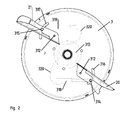
- Fig. 2 Exemplary embodiments of the lens 3 will be described.
- the diffuser 3 is shown schematically in plan view.
- the spreading vanes 20 and 21 are each secured with a bolt 312 in the vicinity of the hub 313 of the lens 3.
- the spreading vanes 20 and 21 are arranged about the bolts 312 schwinkelverschwenkbar. Further support of the spreading vanes 20, 21 on the lens 3 via another bolt 314 and 315.
- the bolts 314 and 315 engage in slots 316 and 317, which are formed in the surface of the lens 3.
- the elongated holes 316 and 317 therefore represent guides for the respective bolts 314 and 315, so that the spreading vanes 20, 21 can be oriented and arranged on the surface of the lens 3 at a predetermined angle to a radial direction of the lens 3.
- actuators 318, 319 can be provided which can engage the respective bolts 314 and 315.
- the actuators 318, 319 may be configured as electrically actuated servo motors be.
- the actuators 318, 319 may be configured as hand-operated devices.
- orientations of the spreading vanes 20 and 21 can be adjusted during a spreading process in order, for example, to adapt to the scattering profile.
- a power supply of the servomotors for example, via lines 320, as in Fig. 2 is shown.
- the lines 320 can be supplied with power, for example via a kind of slip ring device 21.
- the adjusting devices 318, 319 can furthermore be connected to a control or regulating device, which is arranged on the tractor or on the centrifugal fertilizer spreader and not shown. By means of this regulating device, orientations of the spreading vanes 20 and 21 on the spreading disc 3 can then be changed together or separately from the tractor seat, for example, manually or automatically by the regulating device.
- the actuators 318, 319 may be provided with the evaluation unit (see FIG. Fig. 1 ) and controlled by this.
- Fig. 2 Exemplary embodiments described may not constitute a limitation of the present invention and, alternatively, the spreading vanes 20, 21 by at least one fastening means (eg bolts, rivets, etc.) may be attached to the lens 3. In particular, at least one spreading vane 20, 21 may be fixedly mounted on the lens 3.
- fastening means eg bolts, rivets, etc.
- the spreading vanes are not arranged radially aligned on the lens, in particular the spreading vanes may be arranged and oriented such that the angular coordinate is not constant in planar polar coordinates along the lens, ie in planar polar coordinates no radially extending surface or edge is constant Angular coordinate can be attributed.
- the spreading vanes can thus be arranged and oriented in the outer surface of the lens exceptionally outside.
- FIG. 2 shows a greatly simplified plan view of a section of the diffusing screen 3 in an enlarged view, in which only the spreading vane 20 and a particle P of a spreading material are shown schematically. It is noted that Fig. 3 is not a true to scale drawing and in particular the in Fig. 3 shown forces are not drawn to scale.
- the spreading vane 20 is arranged on the lens 3 out of radial, wherein the spreading vane 20 by a distance d from a center M (geometric center, but also intersection of the axis of rotation with the lens) of the lens 3 is spaced such that one to the spreading vane 20 in Fig. 3 parallel straight line (not shown) at a distance d to the spreading vane 20 has the center M.
- a radial direction R passing through the center of gravity of the particle P intersects the spreading vane 20 at an angle ⁇ determined by the radial distance of the particle from the center M and the distance d.
- the radial direction R and a tangential direction T oriented perpendicular to the radial direction R are defined.
- a direction of rotation of the lens 3 is indicated by an arrow D.
- the rotation of the lens 3 occurs at a constant angular velocity, although this is not a limitation of the present invention.
- the particle P experiences a centrifugal force FZ acting along the radial direction and a Coriolis force FC acting along the tangential direction T.
- the Coriolis force FC comprises a normal component FCN which acts perpendicular to the spreading vane 20 and which can be assigned a frictional force FR via a coefficient of friction of the particle P on the spreading vane 20, which counteracts the movement of the particle P along the spreading vane 20.
- the frictional force FR can be divided into a radial component FRR acting along the radial direction R and a tangential component FRT acting along the tangential direction T.
- a spreading vane may be arranged such that the spreading vane with respect to the in Fig. 3 shown spreading vane 20 with a distance greater d is moved from the spreading vane 20 parallel down. It is noted that in this example, not shown, a frictional force on a particle would identify a tangential component that would be executed to the spreading vane. In the example, not shown, an increase in the torque required to drive the lens in the presence of a particle over a radially oriented spreading vane would result.
- the present invention is based on the assumption that the torque for driving the diffusing screen 3 is influenced by the frictional force of the grit, depending on the orientation of the spreading vane.
- Different types of spreading material for example different types of fertilizer, may have different coefficients of friction and / or the coefficient of friction may change depending on the conditions of storage of the material to be spread, so that the friction force may be different and / or dependent on the storage conditions for different types of spreading material. So it was recognized that that Torque for driving the lens 3 in the presence of grit no longer depends only on the mass flow, but also on the type of grit and / or the storage conditions.
- determining a mass flow of spreading material supplied to a lens by measuring a torque of the lens and determining a mass flow from the torque for example, a mass flow torque curve or the like, regardless of the kind of the grit, it is generally assumed in that a value deviating from an actual mass flow is derived.
- FIG. 4 schematically illustrates a flow for detecting a mass flow in a scattering device with a lens for distributing a material supplied to the lens according to some exemplary embodiments of the invention.
- a torque for driving the lens is detected.
- a correction quantity is determined.
- the detected torque is corrected.
- a corrected mass flow is determined based on the corrected torque.
- Fig. 5 schematically illustrates an alternative sequence for detecting a mass flow in a scattering device with a lens for distributing a material supplied to the lens according to other exemplary embodiments of the invention.
- a torque for driving the lens is detected, on the basis of which a mass flow is determined.
- a correction quantity is determined. Based on the correction quantity, the mass flow determined on the basis of the torque is corrected and a corrected mass flow is determined.
- the correction variable can be based on a coefficient of friction of the material on the lens and / or a residence time of the material on the lens and / or a discharge angle of the material relative to a feed direction along which the material flow of the lens is supplied, and / or a discharge direction of the Materials are determined. For example, by means of a discharge angle, below a metered amount of spreading material of the lens a residence time is determined on the basis of which the correction quantity can be determined.
- the coefficient of friction can be derived from the residence time.
- the dwell time may be determined from a mean discharge angle.
- the mean discharge angle may be determined from a maximum in the course of torque over a rotation angle of the disk relative to an application direction.
- the dwell time may be obtained from a camera by taking one or more images of the amount of grit deposited on the lens.
- the coefficient of friction of the material on the lens may be determined by measurements. For example, values for a coefficient of friction of the material of the spreading material with respect to the material of the spreading disk and / or the spreading vanes can be determined from comparison measurements with the material of the spreading material with regard to the material of the spreading disk and / or the spreading vanes.
- a discharge direction can be determined.
- a discharge direction can be derived from a scattering profile, on the basis of which a discharge angle can be determined.
- a discharge direction and / or a middle discharge direction can be determined from a maximum value of material thrown off from sensors arranged circumferentially around the scattering disk or a sensor which can be positioned in the circumferential direction.
- the correction quantity may be determined by means of the evaluation unit on the basis of tables and / or formulas based on theoretical and / or empirical models and / or measured and / or updated characteristics of the friction coefficient and / or the discharge angle and / or the discharge direction and / or the residence time are determined.
- the coefficient of friction is selected from one or more stored databases, tables, empirical values (eg, from previous measurements), LUTs, characteristic curves, or the like, or determined from theoretical or empirical models.
- the data relating to the coefficient of friction of different spreading material can be stored in a memory of the evaluation unit (see FIG Fig. 1 ) to be called up when needed. For example, an operator of the spreader inputs the type of grit into the evaluation unit, or manually selects the grit and the corresponding frictional coefficient from the stored data to determine the frictional coefficient from the deposited data.
- a correction factor can be determined in order to obtain a simple correction of the torque and / or the mass flow.
- the correction factor may be determined from the correction quantity as a function of the radius of the lens and / or a moment of inertia of the lens and / or the speed of the lens and / or a cross-section of the material flow supplied to the lens, wherein the corrected mass flow is based on the correction factor is determined.
- a spreader and a method of determining a corrected mass flow For this purpose, a torque of a lens is detected, which is provided for dispensing a material. Based on the detected torque and a correction quantity based on a friction coefficient of the material on the lens and / or a residence time of the material on the lens and / or a discharge angle of the material relative to a feed direction, along which the material flow of the lens is supplied, and / / or a discharge direction of the material, the corrected mass flow is determined.
Abstract
Es werden eine Streuvorrichtung und ein Verfahren mit einer Bestimmung eines korrigierten Massenstroms bereitgestellt. Hierzu wird ein Drehmoment einer Streuscheibe (3) erfasst, die zum Ausbringen eines Materials vorgesehen ist. Auf Grundlage des erfassten Drehmoments und einer Korrekturgröße basierend auf einem Reibkoeffizienten des Materials auf der Streuscheibe (3) und/oder einer Verweildauer des Materials auf der Streuscheibe (3) und/oder einem Abwurfwinkel des Materials relativ zu einer Zuführrichtung, entlang welcher der Materialstrom der Streuscheibe (3) zugeführt wird, und/oder einer Abwurfrichtung des Materials wird der korrigierte Massenstrom bestimmt.There is provided a spreader and a method of determining a corrected mass flow. For this purpose, a torque of a lens (3) is detected, which is provided for dispensing a material. On the basis of the detected torque and a correction quantity based on a coefficient of friction of the material on the lens (3) and / or a residence time of the material on the lens (3) and / or a release angle of the material relative to a feed direction along which the flow of material Diffuser (3) is supplied, and / or a discharge direction of the material, the corrected mass flow is determined.
Description
Die vorliegende Erfindung betrifft eine Streuvorrichtung und ein Verfahren zum Erfassen eines Massenstroms in einer Streuvorrichtung. Insbesondere betrifft die vorliegende Erfindung eine Streuvorrichtung und ein Verfahren, wobei ein Massenstrom auf Grundlage eines erfassten Drehmoments einer Streuscheibe und einer Korrekturgröße korrigiert wird.The present invention relates to a spreader and a method for detecting a mass flow in a spreader. More particularly, the present invention relates to a spreader and a method wherein a mass flow is corrected based on a detected torque of a diffuser and a correction amount.
In der Landwirtschaft werden sehr große Mengen Mineraldünger ausgebracht, um das Nährstoffangebot für Kulturpflanzen zu ergänzen. Durch gezielte Düngergaben können für Kulturpflanzen schnelleres Wachstum, höhere Erträge und verbesserte Qualitäten erzielt werden, da die benötigten Grundnährstoffe und Spurennährstoffe oftmals im kultivierten Boden nicht in erwünschter Form und Menge bereitstehen. Gerade um einen steigenden Bedarf von Nahrungsmitteln zu begegnen werden im Agrarbereich Düngemittel eingesetzt, um der erforderlichen Steigerung von Erntemengen nachzukommen. Der optimale Einsatz von Düngemitteln ist jedoch nicht nur hinsichtlich der mit Düngemitteln verbundenen Kosten wichtig, sondern auch angesichts der möglichen Gefahren von Belastungen für die Bodenfauna und das Grundwassers bei falscher Düngung notwendig. Zur wirksamen Ertragssteigerung ist es daher unumgänglich, die meist kostenintensiven Düngemittel so zu verteilen, dass sie von den Pflanzen optimal genutzt werden können, ohne eine Gefahr für die Umwelt darzustellen.In agriculture, very large quantities of mineral fertilizers are applied to supplement the nutrient supply for crops. Through targeted fertilizer applications, faster growth, higher yields and improved qualities can be achieved for cultivated plants, since the required basic nutrients and micronutrients are often not available in the cultivated soil in the desired form and quantity. In order to meet the growing demand for food, fertilizers are used in the agricultural sector to meet the required increase in crop yields. The optimal use of fertilizers, however, is not only important in terms of the costs associated with fertilizers, but also in view of the potential hazards of polluting the soil fauna and groundwater in case of incorrect fertilization. For an effective yield increase, it is therefore essential to distribute the most expensive fertilizers so that they can be used optimally by the plants, without posing a threat to the environment.
Für die Ausbringung der Mineraldünger sind im Laufe der Zeit die verschiedenartigsten Verteiltechniken entwickelt worden. Hierbei haben sich insbesondere die Zentrifugaldüngerstreuer durchgesetzt. In entsprechenden bekannten Streuvorrichtungen wird einer rotierenden Streuscheibe ein dosierter Massenstrom zugeführt, der durch Streuschaufeln ausgebracht wird, die auf der Streuscheibe angeordnet sind.For the application of mineral fertilizers, a variety of distribution techniques have been developed over time. Here, in particular, the centrifugal fertilizer spreaders have prevailed. In corresponding known scattering devices, a metered mass flow is supplied to a rotating diffusing screen which is discharged through spreading vanes which are arranged on the diffusing screen.
Damit die auszubringenden Düngemittel möglichst zielgenau verteilt werden können sind an einer Streuvorrichtung vorab Einstellungen vorzunehmen, die auf die als Streugut auszubringende Düngersorte abgestellt sind und die gewünschte Arbeitsbreite festlegen. Im Allgemeinen schwanken die Stoffeigenschaften und die Streueigenschaften für verschiedene Düngemittel sehr stark, so dass die Einsteilungen für jede auszubringenden Düngersorte einzeln zu korrigieren sind. Oftmals sind die Veränderungen in den Stoffeigenschaften für den Landwirt jedoch nicht ohne weiteres erkennbar.So that the fertilizers to be delivered can be distributed as accurately as possible, settings must be made in advance on a spreading device, which are set down on the type of fertilizer to be applied as spreading material and the desired Set working width. In general, the material properties and the scattering properties for different fertilizers vary greatly, so that the pitches for each type of fertilizer to be applied are to be corrected individually. Often, however, the changes in material properties are not readily apparent to the farmer.
Für eine ideale Ausbringung von Düngemitteln ist es ferner erforderlich, die ausgebrachte Menge an Düngemittel genau zu kennen, insbesondere den von einer Streuvorrichtung ausgebrachten Massenstrom genau zu erfassen. In herkömmlichen Schleudervorrichtungen wird der Massenstrom anhand des Drehmoments der Streuscheibe bestimmt. Dabei wird anhand einer vorab gemessenen Massenstrom-Drehmoment-Kennlinie zu einem gemessenen Drehmoment der Streuscheibe der entsprechende Massenstrom bestimmt. Ein entsprechender Schleuderstreuer ist aus Dokument
In diesen herkömmlichen Schleuderstreuern werden jedoch keine stoffabhängigen Eigenschaften unterschiedlicher Arten von Düngemitteln berücksichtigt, so dass bei Verwendung unterschiedlicher Arten von Düngemitteln in der Bestimmung des Massenstroms Fehler auftreten. Auch ist es möglich, dass sich mechanische Eigenschaften einer gelagerten Düngemittelsorte mit der Zeit verändern, z.B. kann die Festigkeit von Partikeln einer gelagerten Düngemittelsorte aufgrund von Feuchtigkeit abnehmen. Die Folge ist ebenfalls eine fehlerhafte Bestimmung des Massenstroms.In these conventional centrifugal spreaders, however, no substance-dependent properties of different types of fertilizers are taken into account, so that when using different types of fertilizers in the determination of the mass flow errors occur. It is also possible that mechanical properties of a stored type of fertilizer will change over time, e.g. For example, the strength of particles of a stored fertilizer variety may decrease due to moisture. The consequence is also an incorrect determination of the mass flow.
Ausgehend von dem vorangehend dargestellten Stand der Technik ist es eine Aufgabe, eine Streuvorrichtung und ein Verfahren bereitzustellen, das die oben genannten Probleme vermeidet.On the basis of the above-described prior art, it is an object to provide a scattering device and a method which avoids the above-mentioned problems.
Die vorliegende Erfindung schlägt als Lösung eine Streuvorrichtung und ein Verfahren zum Erfassen eines Massenstroms in einer Streuvorrichtung vor, wobei ein korrigierter Massenstrom auf Grundlage einer Korrekturgröße und eines erfassten Drehmoments bestimmt ist.The present invention proposes as a solution a spreader and a method for detecting a mass flow in a spreader, wherein a corrected mass flow is determined based on a correction quantity and a detected torque.
In einem Aspekt der vorliegenden Erfindung wird ein Verfahren zum Erfassen eines Massenstroms in einer Streuvorrichtung mit einer Streuscheibe zum Verteilen von der Streuscheibe zugeführtem Material bereitgestellt. In beispielhaften Ausführungsformen umfasst das Verfahren ein Antreiben der wenigstens einen Streuscheibe, so dass diese um eine Drehachse rotiert, ein Zuführen des Materials zu der wenigstens einen rotierenden Streuscheibe, ein Erfassen eines zum Antrieb der wenigstens einen rotierenden Streuscheibe erforderlichen Drehmoments und ein Bestimmen eines korrigierten Massenstroms des der Streuscheibe zugeführten Materials auf Grundlage der Korrekturgröße und des erfassten Drehmoments. Die Korrekturgröße kann dabei auf einem Reibkoeffizienten des Materials auf der Streuscheibe und/oder einer Verweildauer des Materials auf der Streuscheibe und/oder einem Abwurfwinkel des Materials relativ zu einer Zuführrichtung, entlang welcher der Materialstrom der Streuscheibe zugeführt wird, und/oder einer Abwurfrichtung des Materials basieren. Durch die Korrekturgröße wird hierbei eine Bestimmung eines korrigierten Massenstroms erreicht, wobei Reibungseinflüsse auf die Bestimmung des Massenstroms, die von der verwendeten Düngemittelsorte abhängen, berücksichtigt werden. Es ist also eine genauere Bestimmung der ausgebrachten Masse möglich, ohne dass für unterschiedliche Düngemittelsorten unter verschiedenen Bedingungen Drehmoment-Massenstrom-Beziehungen zu ermitteln sind.In one aspect of the present invention, there is provided a method of detecting a mass flow in a spreader having a diffuser for distributing material supplied to the diffuser. In exemplary embodiments, the method includes driving the at least one diffuser to rotate about an axis of rotation, feeding the material to the at least one rotating diffuser, detecting a torque required to drive the at least one rotating diffuser, and determining a corrected mass flow the material supplied to the lens based on the correction amount and the detected torque. The correction variable can be based on a coefficient of friction of the material on the lens and / or a residence time of the material on the lens and / or a discharge angle of the material relative to a feed direction along which the material flow of the lens is supplied, and / or a discharge direction of the material based. In this case, a determination of a corrected mass flow is achieved by the correction variable, taking into account friction effects on the determination of the mass flow, which depend on the type of fertilizer used. Thus, a more accurate determination of the applied mass is possible without torque-mass flow relationships having to be determined for different types of fertilizer under different conditions.
In einer weiteren vorteilhafteren Ausgestaltung hierin kann das Bestimmen des korrigierten Massenstroms ein Bestimmen eines korrigierten Drehmoments auf Grundlage der Korrekturgröße und ein Bestimmen des korrigierten Massenstroms aus dem korrigierten Drehmoment mittels einer bekannten Massenstrom-Drehmoment-Beziehung umfassen. Hierbei können Einflüsse berücksichtigt werden, die sich auf das Drehmoment auswirken, ohne dass neue Drehmoment-Massenstrom-Beziehungen vorab aufgenommen werden müssen. Es wird somit eine genaue Massenbestimmung ermöglicht.In another more advantageous embodiment herein, determining the corrected mass flow may include determining a corrected torque based on the correction quantity and determining the corrected mass flow from the corrected torque using a known mass flow-torque relationship. It can take into account influences that affect the torque without having to pre-record new torque-mass flow relationships. Thus, an accurate mass determination is possible.
In einer anderen vorteilhafteren Ausgestaltung hierin kann das Bestimmen des korrigierten Massenstroms ein Bestimmen eines Massenstromwerts aus einer bekannten Massenstrom-Drehmoment-Beziehung auf Grundlage des erfassten Drehmoments und ein Korrigieren des Massenstromwerts auf Grundlage der Korrekturgröße umfassen. Hierbei kann eine Korrektur unter Berücksichtigung verschiedener Einflüsse auf eine einfache Weise erfolgen.In another more advantageous embodiment herein, determining the corrected mass flow may include determining a mass flow value from a known mass flow-torque relationship based on the detected mass flow Torque and correcting the mass flow value based on the correction amount include. In this case, a correction taking into account various influences in a simple manner.
In einigen vorteilhaften Ausgestaltungen kann das Verfahren ferner ein Bestimmen eines Korrekturfaktors aus der Korrekturgröße in Abhängigkeit von dem Radius der Streuscheibe und/oder einem Trägheitsmoment der Streuscheibe und/oder einer Drehzahl der Streuscheibe und/oder einem Querschnitt des der Streuscheibe zugeführten Materialstroms umfassen, wobei der korrigierte Massenstrom auf Grundlage des Korrekturfaktors bestimmt wird. Abhängig von Streuscheibenparametern kann anhand eines Korrekturfaktors eine einfache Korrektur bereitgestellt werden, die unterschiedliche Scheibenkonfigurationen berücksichtigt.In some advantageous embodiments, the method may further comprise determining a correction factor from the correction quantity as a function of the radius of the lens and / or a moment of inertia of the lens and / or a speed of the lens and / or a cross-section of the stream of material supplied to the lens, wherein the corrected mass flow is determined based on the correction factor. Depending on lens parameters, a correction factor can be provided based on a correction factor that takes into account different lens configurations.
In einigen vorteilhaften Ausgestaltungen kann das Bestimmen der Korrekturgröße ein Erfassen des Reibkoeffizienten und/oder des Abwurfwinkels und/oder der Abwurfrichtung mittels eines Schallsensors und/oder eines Lichtsensors und/oder eines Kraftsensors und/oder einer Videokamera und/oder einer Radarsensorvorrichtung umfassen. Hierbei kann die Korrekturgröße auf eine einfache Weise bestimmt werden.In some advantageous embodiments, the determination of the correction variable may include detecting the friction coefficient and / or the discharge angle and / or the discharge direction by means of a sound sensor and / or a light sensor and / or a force sensor and / or a video camera and / or a radar sensor device. Here, the correction amount can be determined in a simple manner.
In einigen vorteilhaften Ausgestaltungen kann das Bestimmen der Korrekturgröße ein Auswählen des Reibkoeffizienten aus einer oder mehreren hinterlegten Datenbanken, Tabellen, Erfahrungswerten oder Kennlinien umfassen. Damit wird eine einfache Korrektur des Massenstroms auf Basis hinterlegter Daten des Reibkoeffizienten ermöglicht.In some advantageous embodiments, determining the correction variable may include selecting the friction coefficient from one or more stored databases, tables, empirical values or characteristics. This allows a simple correction of the mass flow on the basis of stored data of the friction coefficient.
In einigen vorteilhaften Ausgestaltungen kann die Streuscheibe ferner wenigstens eine Streuschaufel aufweisen, die mit Bezug auf die Drehachse außerradial angeordnet ist. Bei Streuscheiben mit wenigstens einer außerradial angeordneten Streuschaufel kann unabhängig vom Reibverhalten des Materials eine genaue Massenbestimmung erfolgen.In some advantageous embodiments, the lens may further comprise at least one spreading vane, which is arranged with respect to the rotational axis out of radial. When spreading discs with at least one out-of-round spreading vane can be done regardless of the friction behavior of the material an accurate mass determination.
In einem anderen Aspekt der vorliegenden Erfindung wird eine Streuvorrichtung bereitgestellt. In anschaulichen Ausgestaltungen kann die Streuvorrichtung wenigstens eine Streuscheibe, die zur Drehung um eine Drehachse konfiguriert ist, um der Streuscheibe zugeführtes Material in einem Abwurfwinkelbereich auszubringen, eine Drehmomenterfassungsvorrichtung, die zum Erfassen eines Drehmoments konfiguriert ist, das zum Antrieb der wenigstens einen Streuscheibe dieser zugeführt wird, eine Sensorvorrichtung, die zum Erfassen von einer Korrekturgröße konfiguriert ist, und eine elektronische Auswertungseinheit umfassen, die zum Bestimmen eines korrigierten Massenstroms des der Streuscheibe zugeführten Materials auf Grundlage der Korrekturgröße und des von der Drehmomenterfassungsvorrichtung erfassten Drehmoments konfiguriert ist. Dabei kann die Korrekturgröße auf einem Reibkoeffizienten des Materials auf der Streuscheibe und/oder einer Verweildauer des Materials auf der Streuscheibe und/oder einem Abwurfwinkel des Materials relativ zu einer Zuführrichtung, entlang welcher der Streuscheibe der Materialstrom zugeführt wird, und/oder einer Abwurfrichtung des Materials basieren. Durch die Korrekturgröße wird hierbei eine Bestimmung eines korrigierten Massenstroms erreicht, wobei Reibungsabhängige Einflüsse auf die Bestimmung des Massenstroms, die von der verwendeten Düngemittelsorte abhängen, berücksichtigt werden. Es ist also eine genauere Bestimmung der ausgebrachten Masse möglich, ohne dass für unterschiedliche Düngemittelsorten unter verschiedenen Bedingungen Drehmoment-Massenstrom-Beziehungen zu ermitteln sind.In another aspect of the present invention, a spreader is provided. In illustrative embodiments, the spreader may include at least one diffuser configured to rotate about an axis of rotation to expose material to the diffuser in a firing angle range, a torque sensing device configured to detect a torque supplied to drive the at least one diffuser , a sensor device configured to detect a correction amount, and an electronic evaluation unit configured to determine a corrected mass flow of the lens supplied material based on the correction amount and the torque detected by the torque detecting device. In this case, the correction quantity can be based on a coefficient of friction of the material on the lens and / or a residence time of the material on the lens and / or a discharge angle of the material relative to a feed direction, along which the material flow is supplied to the lens, and / or a discharge direction of the material based. By the correction quantity, a determination of a corrected mass flow is achieved, whereby friction-dependent influences on the determination of the mass flow, which depend on the type of fertilizer used, are taken into account. Thus, a more accurate determination of the applied mass is possible without torque-mass flow relationships having to be determined for different types of fertilizer under different conditions.
In einer vorteilhafteren Ausgestaltung hierin kann die elektronische Auswertungseinheit zum Bestimmen eines korrigierten Drehmoments auf Grundlage der Korrekturgröße und zum Zugriff auf eine bekannte Massenstrom-Drehmoment-Beziehung konfiguriert sein, um den korrigierten Massenstroms auf Grundlage des korrigierten Drehmoments mittels der bekannten Massenstrom-Drehmoment-Beziehung zu bestimmen. Hierbei können durch die Auswertungseinheit Einflüsse berücksichtigt werden, die sich auf das Drehmoment auswirken, ohne dass neue Drehmoment-Massenstrom-Beziehungen vorab aufgenommen werden müssen. Es wird somit eine genaue Massenbestimmung ermöglicht.In a more advantageous embodiment herein, the electronic evaluation unit may be configured to determine a corrected torque based on the correction quantity and access a known mass flow torque relationship to increase the corrected mass flow based on the corrected torque using the known mass flow torque relationship determine. In this case, influences that have an effect on the torque can be taken into account by the evaluation unit without having to presume new torque-mass flow relationships in advance. Thus, an accurate mass determination is possible.
In einer anderen vorteilhafteren Ausgestaltung hierin kann die elektronische Auswertungseinheit ferner zum Zugriff auf eine bekannte Massenstrom-Drehmoment-Beziehung, zum Bestimmen des korrigierten Massenstroms mittels eines Bestimmens eines Massenstromwerts auf Grundlage der bekannten Massenstrom-Drehmoment-Beziehung und des erfassten Drehmoments und zum Korrigieren des Massenstromwerts auf Grundlage der Korrekturgröße konfiguriert sein. Hierbei kann durch die Auswertungseinheit auf eine einfache Weise eine Korrektur unter Berücksichtigung verschiedener Einflüsse erfolgen.In another more advantageous embodiment herein, the electronic evaluation unit may further access a known mass flow torque relationship, determine the corrected mass flow by determining a mass flow value based on the known mass flow torque relationship and the detected torque, and correcting the mass flow value be configured based on the correction amount. Here, by the evaluation unit in a simple manner, a correction taking into account various influences.
In einigen vorteilhaften Ausgestaltungen kann die elektronische Auswertungseinheit ferner zum Bestimmen eines Korrekturfaktors aus der Korrekturgröße in Abhängigkeit von dem Radius der Streuscheibe und/oder einem Trägheitsmoment der Streuscheibe und/oder der Drehzahl der Streuscheibe und/oder einem Querschnitt des der Streuscheibe zugeführten Materialstroms konfiguriert sein, um den korrigierten Massenstrom auf Grundlage des Korrekturfaktors zu bestimmen. Abhängig von Streuscheibenparametern kann die Auswertungseinheit anhand eines Korrekturfaktors eine einfache Korrektur ermöglichen, in der auch unterschiedliche Scheibenkonfigurationen berücksichtigt sind.In some advantageous embodiments, the electronic evaluation unit can also be configured for determining a correction factor from the correction variable as a function of the radius of the lens and / or an inertia of the lens and / or the speed of the lens and / or a cross section of the material flow supplied to the lens, to determine the corrected mass flow based on the correction factor. Depending on the spreading lens parameters, the evaluation unit can use a correction factor to enable a simple correction in which different disk configurations are also taken into account.
In einigen vorteilhaften Ausgestaltungen kann die elektronische Auswertungseinheit ferner einen Speicher mit einer oder mehreren darin hinterlegten Datenbanken, Tabellen, Erfahrungswerten oder Kennlinien zum Bestimmen der Korrekturgröße auf Grundlage des Reibkoeffizienten umfassen. Damit ermöglicht die Streuvorrichtung eine einfache Korrektur des Massenstroms auf Basis von im Speicher der Auswertungseinheit hinterlegten Daten des Reibkoeffizienten.In some advantageous embodiments, the electronic evaluation unit may further comprise a memory with one or more databases, tables, empirical values or characteristic curves stored therein for determining the correction variable on the basis of the friction coefficient. Thus, the scattering device allows a simple correction of the mass flow based on stored in the memory of the evaluation unit data of the friction coefficient.
In einigen vorteilhaften Ausgestaltungen kann die Sensorvorrichtung wenigstens einen Schallsensor und/oder einen Lichtsensor und/oder einen Kraftsensor und/oder eine Videokamera und/oder eine Radarsensorvorrichtung umfassen. Hierbei kann Sensorvorrichtung eine einfache Bestimmung der Korrekturgröße ermöglichen.In some advantageous embodiments, the sensor device may comprise at least one sound sensor and / or a light sensor and / or a force sensor and / or a video camera and / or a radar sensor device. In this case, sensor device can enable a simple determination of the correction quantity.
In einigen vorteilhaften Ausgestaltungen kann die Streuscheibe wenigstens eine Streuschaufel aufweisen, die mit Bezug auf die Drehachse außerradial angeordnet ist.In some advantageous embodiments, the lens may have at least one spreading vane, which is arranged non-radially with respect to the axis of rotation.
Weitere Merkmale, vorteilhafte Ausführungsformen und Vorteile der vorliegenden Erfindung gehen aus den beigefügten Patentansprüchen und der folgenden detaillierten Beschreibung anschaulicher Ausführungsformen hervor, wobei auf die folgenden Figuren Bezug genommen wird.
- Fig. 1
- zeigt schematisch eine Streuvorrichtung gemäß einigen anschaulichen Ausführungsformen der vorliegenden Erfindung;
- Fig. 2
- zeigt schematisch eine Aufsicht auf eine Streuscheibe gemäß einigen anschaulichen Ausführungsformen der vorliegenden Erfindung;
- Fig. 3
- zeigt schematisch eine Prinzipskizze eines Ausschnitts einer Streuscheibe in Vergrößerung während des Betriebs in Aufsicht gemäß beispielhafter Ausführungsformen der vorliegenden Erfindung;
- Fig. 4
- zeigt schematisch ein Ablaufdiagramm zur Bestimmung eines korrigierten Massenstroms gemäß einigen anschaulichen Ausführungsformen der Erfindung; und
- Fig. 5
- zeigt schematisch ein weiteres Ablaufdiagramm zur Bestimmung eines korrigierten Massenstroms gemäß anderen anschaulichen Ausführungsformen der Erfindung.
- Fig. 1
- schematically shows a scattering device according to some illustrative embodiments of the present invention;
- Fig. 2
- FIG. 12 schematically illustrates a top view of a lens according to some illustrative embodiments of the present invention; FIG.
- Fig. 3
- schematically shows a schematic diagram of a section of a lens in magnification during operation in plan view according to exemplary embodiments of the present invention;
- Fig. 4
- schematically shows a flowchart for determining a corrected mass flow according to some illustrative embodiments of the invention; and
- Fig. 5
- schematically shows another flowchart for determining a corrected mass flow according to other illustrative embodiments of the invention.
Der Antrieb der Streuscheibe 3 kann beispielsweise durch die Zapfwelle eines Traktors 18 über ein Getriebe 26 erfolgen. Alternativ kann die Streuscheibe 3 durch einen Hydraulikmotor (nicht dargestellt) oder über geeignete Einrichtungen angetrieben werden, wie z.B. durch die Hydraulikanlage eines Schleppers oder eine Hydraulikpumpe, die von dem Schlepper oder mit anderen Mitteln motorisch angetrieben wird. Dem Antrieb der Streuscheibe 3 kann eine Regeleinrichtung (nicht dargestellt) zugeordnet sein, mittels der eine Drehzahl der Streuscheibe 3 eingestellt werden kann.The drive of the
Ferner kann ein Drehzahlsensor 14 vorgesehen sein, um die Drehzahl der Streuscheibe 3 zu erfassen. Ein zum Antrieb der Streuscheibe 3 zugeführtes Drehmoment kann über einen Drehmomentsensor 8 erfasst werden. Ferner kann ein Drehwinkelsensor 16 vorgesehen sein, mittels welchem der Drehwinkel der Schleuderscheibe 3 ermittelbar ist.Further, a
Ferner ist eine Auswertungseinheit 15 vorgesehen, wie in
Des Weiteren ist eine in Umfangsrichtung der Streuscheibe 3 positionierbare Sensoranordnung 19 vorgesehen, um ein Streuprofil von einem durch die Streuscheibe ausgebrachten Massenstrom zu erfassen. Durch den Sensor 19 kann z.B. eine Streubreite des ausgebrachten Massenstroms erfasst werden. Alternativ kann die Sensoranordnung 19 eine Vielzahl von Sensoren umfassen, die um die Streuscheibe 3 in Umfangsrichtung angeordnet sind. Gemäß beispielhaften Ausführungsformen kann die Sensoranordnung 19 wenigstens einen optischen Sensor und/oder wenigstens einen Kraftsensor umfassen. Zusätzlich oder alternativ kann die Sensoranordnung 19 eine Kamera aufweisen. Zusätzlich oder alternativ kann die Sensorvorrichtung 19 eine Radarsensorvorrichtung umfassen. Die Sensoranordnung 19 steht mit der Auswertungseinheit 15 in Verbindung, so dass von der Sensoranordnung 19 erfasste Daten der Auswertungseinheit übermittelt werden können.Furthermore, a positionable in the circumferential direction of the
Anhand von
In beispielhaften Ausführungsformen, in denen elektrische Stellmotoren vorgesehen sind, kann eine Energieversorgung der Stellmotoren bspw. über Leitungen 320 erfolgen, wie in
Es wird angemerkt, dass die anhand von
In allgemeinen Orientierungen sind die Streuschaufeln auf der Streuscheibe nicht radial ausgerichtet angeordnet, insbesondere können die Streuschaufeln derart angeordnet und orientiert sein, dass die Winkelkoordinate in ebenen Polarkoordinaten entlang der Streuscheibe nicht konstant ist, d.h. in ebenen Polarkoordinaten keiner sich radial erstreckenden Fläche oder Kante eine konstante Winkelkoordinate zugeschrieben werden kann. Die Streuschaufeln können also im Allgemeinen in der Oberfläche der Streuscheibe außerradial angeordnet und orientiert sein.In general orientations, the spreading vanes are not arranged radially aligned on the lens, in particular the spreading vanes may be arranged and oriented such that the angular coordinate is not constant in planar polar coordinates along the lens, ie in planar polar coordinates no radially extending surface or edge is constant Angular coordinate can be attributed. The spreading vanes can thus be arranged and oriented in the outer surface of the lens exceptionally outside.
Anhand von
Die Streuschaufel 20 ist auf der Streuscheibe 3 außerradial angeordnet, wobei die Streuschaufel 20 um einen Abstand d von einem Mittelpunkt M (geometrischer Mittelpunkt, aber auch Schnittpunkt der Drehachse mit der Streuscheibe) der Streuscheibe 3 derart beabstandet ist, dass eine zu der Streuschaufel 20 in
Bezüglich des Partikels P sind die radiale Richtung R und eine tangentiale Richtung T definiert, die senkrecht zu der radialen Richtung R orientiert ist. Eine Drehrichtung der Streuscheibe 3 wird durch einen Pfeil D bezeichnet. Die Drehung der Streuscheibe 3 erfolgt bei konstanter Winkelgeschwindigkeit, obgleich dies keine Beschränkung der vorliegenden Erfindung darstellt.With respect to the particle P, the radial direction R and a tangential direction T oriented perpendicular to the radial direction R are defined. A direction of rotation of the
Das Partikel P erfährt durch die Drehbewegung der Streuscheibe 3 eine entlang der radialen Richtung wirkende Zentrifugalkraft FZ und eine entlang der tangentialen Richtung T wirkende Corioliskraft FC. Die Corioliskraft FC umfasst eine senkrecht auf die Streuschaufel 20 wirkende Normalenkomponente FCN, die über einen Reibkoeffizienten des Partikels P auf der Streuschaufel 20 einer Reibungskraft FR zugeordnet werden kann, die der Bewegung des Partikels P entlang der Streuschaufel 20 entgegenwirkt. Die Reibungskraft FR lässt sich in eine entlang der radialen Richtung R wirkende radiale Komponente FRR und in eine entlang der tangentialen Richtung T wirkende tangentiale Komponente FRT zerlegen, da die die radiale Richtung R und die Streuschaufel 20 den von 0° verschiedenen Winkel α bilden. Die entlang der tangentialen Richtung wirkenden Kräfte ergeben ein Drehmoment M, das der Streuscheibe 3 zugeführt wird, um das Partikel P entlang der Streuschaufel 20 zu beschleunigen. Wie in
Die in
Die vorliegende Erfindung geht davon aus, dass das Drehmoment zum Antrieb der Streuscheibe 3 abhängig von der Orientierung der Streuschaufel durch die Reibungskraft des Streuguts beeinflusst wird. Unterschiedliche Arten von Streugut, beispielsweise unterschiedliche Arten von Düngemittel, können unterschiedliche Reibkoeffizienten aufweisen und/oder der Reibkoeffizient kann sich abhängig von den Lagerungsbedingungen des Streuguts ändern, so dass die Reibungskraft für unterschiedliche Arten von Streugut verschieden und/oder von den Lagerungsbedingungen abhängen kann. Es wurde also erkannt, dass das Drehmoment zum Antrieb der Streuscheibe 3 in Gegenwart von Streugut nicht mehr nur vom Massenstrom, sondern auch von der Art des Streuguts und/oder den Lagerungsbedingungen abhängt. Bei einer Bestimmung eines Massenstroms von Streugut, das einer Streuscheibe zugeführt wird, durch Messen eines Drehmoments der Streuscheibe und Bestimmen eines Massenstroms aus dem Drehmoment, beispielsweise anhand einer Massenstrom-Drehmoment-Kennlinie oder dergleichen, ohne Berücksichtigung der Art des Streuguts ist im Allgemeinen davon auszugehen, dass ein von einem tatsächlichen Massenstrom abweichender Wert abgeleitet wird.The present invention is based on the assumption that the torque for driving the
Anhand der
Die Korrekturgröße kann dabei auf Basis eines Reibkoeffizienten des Materials auf der Streuscheibe und/oder einer Verweildauer des Materials auf der Streuscheibe und/oder einem Abwurfwinkel des Materials relativ zu einer Zuführrichtung, entlang welcher der Materialstrom der Streuscheibe zugeführt wird, und/oder einer Abwurfrichtung des Materials bestimmt werden. Beispielsweise kann mittels eines Abwurfwinkels, unter dem einen dosierte Menge an Streugut der Streuscheibe zugeführt wird, eine Verweildauer bestimmt werden, auf deren Grundlage die Korrekturgröße bestimmt werden kann.The correction variable can be based on a coefficient of friction of the material on the lens and / or a residence time of the material on the lens and / or a discharge angle of the material relative to a feed direction along which the material flow of the lens is supplied, and / or a discharge direction of the Materials are determined. For example, by means of a discharge angle, below a metered amount of spreading material of the lens a residence time is determined on the basis of which the correction quantity can be determined.
In einem speziellen Beispiel kann der Reibkoeffizient aus der Verweildauer abgeleitet werden.In a specific example, the coefficient of friction can be derived from the residence time.
In einem speziellen Beispiel kann die Verweildauer aus einem mittleren Abwurfwinkel bestimmt werden. Zum Beispiel kann der mittlere Abwurfwinkel aus einem Maximal im Verlauf des Drehmoments über einem Drehwinkel der Scheibe relativ zu einer Aufbringrichtung bestimmt werden. In einem anderen Beispiel kann die Verweildauer anhand einem oder mehreren Bildern von der auf die Streuscheibe aufgebrachten Streugutmenge aufgenommen durch eine Kamera erhalten werden.In a specific example, the dwell time may be determined from a mean discharge angle. For example, the mean discharge angle may be determined from a maximum in the course of torque over a rotation angle of the disk relative to an application direction. In another example, the dwell time may be obtained from a camera by taking one or more images of the amount of grit deposited on the lens.
Zusätzlich oder alternativ kann der Reibkoeffizient des Materials auf der Streuscheibe durch Messungen bestimmt werden. Beispielsweise können aus Vergleichsmessungen zum Material des Streuguts hinsichtlich des Materials der Streuscheibe und/oder der Streuschaufeln Werte für einen Reibkoeffizienten des Materials des Streuguts hinsichtlich des Materials der Streuscheibe und/oder der Streuschaufeln bestimmt werden.Additionally or alternatively, the coefficient of friction of the material on the lens may be determined by measurements. For example, values for a coefficient of friction of the material of the spreading material with respect to the material of the spreading disk and / or the spreading vanes can be determined from comparison measurements with the material of the spreading material with regard to the material of the spreading disk and / or the spreading vanes.
Zusätzlich oder alternativ kann eine Abwurfrichtung bestimmt werden. Beispielsweise kann aus einem Streuprofil eine Abwurfrichtung abgeleitet werden, auf deren Grundlage ein Abwurfwinkel bestimmt werden kann. In einem konkreten Beispiel können aus in Umfangsrichtung um die Streuscheibe angeordneten Sensoren bzw. einem in Umfangsrichtung positionierbaren Sensor eine Abwurfrichtung und/oder eine mittlere Abwurfrichtung aus einem maximalen Wert an abgeworfenem Material bestimmt werden.Additionally or alternatively, a discharge direction can be determined. For example, a discharge direction can be derived from a scattering profile, on the basis of which a discharge angle can be determined. In a concrete example, a discharge direction and / or a middle discharge direction can be determined from a maximum value of material thrown off from sensors arranged circumferentially around the scattering disk or a sensor which can be positioned in the circumferential direction.
In einigen beispielhaften Ausführungsformen kann die Korrekturgröße mittels der Auswertungseinheit auf Basis von Tabellen, und/oder Formeln basierend auf theoretischen und/oder empirischen Modellen, und/oder gemessenen und/oder aktualisierten Kennlinien aus dem Reibkoeffizienten und/oder dem Abwurfwinkel und/oder der Abwurfrichtung und/oder der Verweildauer bestimmt werden. In einigen beispielhaften Ausführungsformen wird der Reibkoeffizient aus einer oder mehreren hinterlegten Datenbanken, Tabellen, Erfahrungswerten (z.B. aus vorab durchgeführten Messungen), LUTs, Kennlinien oder dergleichen ausgewählt oder aus theoretischen oder empirischen Modellen ermittelt. Dazu können die den Reibkoeffizient von unterschiedlichem Streugut betreffenden Daten in einem Speicher der Auswertungseinheit (vgl. 15 in
In einigen beispielhaften Ausführungsformen kann z.B. basierend auf der Korrekturgröße ein Korrekturfaktor bestimmt werden, um eine einfache Korrektur des Drehmoments und/oder des Massenstroms zu erhalten. In einigen Beispielen hierin kann der Korrekturfaktor aus der Korrekturgröße in Abhängigkeit von dem Radius der Streuscheibe und/oder einem Trägheitsmoment der Streuscheibe und/oder der Drehzahl der Streuscheibe und/oder einem Querschnitt des der Streuscheibe zugeführten Materialstroms bestimmt werden, wobei der korrigierte Massenstrom basierend auf dem Korrekturfaktor bestimmt wird.In some example embodiments, e.g. based on the correction quantity, a correction factor can be determined in order to obtain a simple correction of the torque and / or the mass flow. In some examples herein, the correction factor may be determined from the correction quantity as a function of the radius of the lens and / or a moment of inertia of the lens and / or the speed of the lens and / or a cross-section of the material flow supplied to the lens, wherein the corrected mass flow is based on the correction factor is determined.
Es werden eine Streuvorrichtung und ein Verfahren mit einer Bestimmung eines korrigierten Massenstroms bereitgestellt. Hierzu wird ein Drehmoment einer Streuscheibe erfasst, die zum Ausbringen eines Materials vorgesehen ist. Auf Grundlage des erfassten Drehmoments und einer Korrekturgröße basierend auf einem Reibkoeffizienten des Materials auf der Streuscheibe und/oder einer Verweildauer des Materials auf der Streuscheibe und/oder einem Abwurfwinkel des Materials relativ zu einer Zuführrichtung, entlang welcher der Materialstrom der Streuscheibe zugeführt wird, und/oder einer Abwurfrichtung des Materials wird der korrigierte Massenstrom bestimmt.There is provided a spreader and a method of determining a corrected mass flow. For this purpose, a torque of a lens is detected, which is provided for dispensing a material. Based on the detected torque and a correction quantity based on a friction coefficient of the material on the lens and / or a residence time of the material on the lens and / or a discharge angle of the material relative to a feed direction, along which the material flow of the lens is supplied, and / / or a discharge direction of the material, the corrected mass flow is determined.
Claims (14)
Applications Claiming Priority (1)
| Application Number | Priority Date | Filing Date | Title |
|---|---|---|---|
| DE102014102645.4A DE102014102645A1 (en) | 2014-02-28 | 2014-02-28 | Spreader and method for detecting a mass flow in a spreader |
Publications (2)
| Publication Number | Publication Date |
|---|---|
| EP2912934A1 true EP2912934A1 (en) | 2015-09-02 |
| EP2912934B1 EP2912934B1 (en) | 2018-08-22 |
Family
ID=52633206
Family Applications (1)
| Application Number | Title | Priority Date | Filing Date |
|---|---|---|---|
| EP15401013.6A Active EP2912934B1 (en) | 2014-02-28 | 2015-02-25 | Distribution device and method for detecting a mass flow in a distribution device |
Country Status (3)
| Country | Link |
|---|---|
| EP (1) | EP2912934B1 (en) |
| DE (1) | DE102014102645A1 (en) |
| DK (1) | DK2912934T3 (en) |
Cited By (3)
| Publication number | Priority date | Publication date | Assignee | Title |
|---|---|---|---|---|
| EP3025571A1 (en) * | 2014-11-27 | 2016-06-01 | Amazonen-Werke H. Dreyer GmbH & Co. KG | Centrifugal spreader for distribution of spread material |
| CN105917829A (en) * | 2016-05-29 | 2016-09-07 | 广东技术师范学院 | Fertilizer applying apparatus for greenhouses vegetable cultivation |
| CN106258126A (en) * | 2016-08-06 | 2017-01-04 | 王华银 | Fertilizer tossed device |
Families Citing this family (5)
| Publication number | Priority date | Publication date | Assignee | Title |
|---|---|---|---|---|
| DE102015116948A1 (en) * | 2015-10-06 | 2017-04-06 | Amazonen-Werke H. Dreyer Gmbh & Co. Kg | Method for the release angle control of a centrifugal spreader |
| DE102015116946A1 (en) * | 2015-10-06 | 2017-04-06 | Amazonen-Werke H. Dreyer Gmbh & Co. Kg | Method for drop angle adjustment of a centrifugal spreader |
| DE102016108166A1 (en) * | 2016-05-03 | 2017-11-09 | Amazonen-Werke H. Dreyer Gmbh & Co. Kg | Control system for an agricultural machine and method |
| DE102016108176A1 (en) * | 2016-05-03 | 2017-11-09 | Amazonen-Werke H. Dreyer Gmbh & Co. Kg | Control system for an agricultural machine and method |
| DE102018110878A1 (en) * | 2018-05-07 | 2020-03-19 | Amazonen-Werke H. Dreyer Gmbh & Co. Kg | Method for operating an agricultural spreader |
Citations (3)
| Publication number | Priority date | Publication date | Assignee | Title |
|---|---|---|---|---|
| DE4417549A1 (en) * | 1994-05-19 | 1995-11-23 | Bosch Gmbh Robert | Device for dispensing and distributing grit or deicing salt |
| EP0963690A1 (en) * | 1998-06-10 | 1999-12-15 | Rauch Landmaschinenfabrik Gmbh | Centrifugal spreader |
| DE19908141A1 (en) * | 1999-02-25 | 2000-08-31 | Rauch Landmaschfab Gmbh | Centrifugal spreader for distributing material, e.g. for treating roads in winter or for agricultural use |
-
2014
- 2014-02-28 DE DE102014102645.4A patent/DE102014102645A1/en not_active Withdrawn
-
2015
- 2015-02-25 EP EP15401013.6A patent/EP2912934B1/en active Active
- 2015-02-25 DK DK15401013.6T patent/DK2912934T3/en active
Patent Citations (4)
| Publication number | Priority date | Publication date | Assignee | Title |
|---|---|---|---|---|
| DE4417549A1 (en) * | 1994-05-19 | 1995-11-23 | Bosch Gmbh Robert | Device for dispensing and distributing grit or deicing salt |
| EP0963690A1 (en) * | 1998-06-10 | 1999-12-15 | Rauch Landmaschinenfabrik Gmbh | Centrifugal spreader |
| EP0963690B1 (en) | 1998-06-10 | 2004-09-01 | Rauch Landmaschinenfabrik Gmbh | Centrifugal spreader |
| DE19908141A1 (en) * | 1999-02-25 | 2000-08-31 | Rauch Landmaschfab Gmbh | Centrifugal spreader for distributing material, e.g. for treating roads in winter or for agricultural use |
Cited By (5)
| Publication number | Priority date | Publication date | Assignee | Title |
|---|---|---|---|---|
| EP3025571A1 (en) * | 2014-11-27 | 2016-06-01 | Amazonen-Werke H. Dreyer GmbH & Co. KG | Centrifugal spreader for distribution of spread material |
| CN105917829A (en) * | 2016-05-29 | 2016-09-07 | 广东技术师范学院 | Fertilizer applying apparatus for greenhouses vegetable cultivation |
| CN105917829B (en) * | 2016-05-29 | 2017-11-07 | 广东技术师范学院 | A kind of booth vegetable cultivation fertilizer apparatus |
| CN106258126A (en) * | 2016-08-06 | 2017-01-04 | 王华银 | Fertilizer tossed device |
| CN106258126B (en) * | 2016-08-06 | 2018-08-28 | 连云港大陆农业机械装备有限公司 | Fertilizer tossed device |
Also Published As
| Publication number | Publication date |
|---|---|
| EP2912934B1 (en) | 2018-08-22 |
| DE102014102645A1 (en) | 2015-09-03 |
| DK2912934T3 (en) | 2018-12-10 |
Similar Documents
| Publication | Publication Date | Title |
|---|---|---|
| EP2912934B1 (en) | Distribution device and method for detecting a mass flow in a distribution device | |
| EP2556738B1 (en) | Method for controlling a centrifugal manure spreader | |
| DE102011050474A1 (en) | Agricultural device | |
| EP3241421B1 (en) | Control system for an agricultural machine and method | |
| EP3017678B1 (en) | Method and device for calculating adjusting parameters of a centrifugal spreader | |
| EP3017679A1 (en) | Method for detecting the speed and/or throw radius of ejected spread goods, and a distribution machine for performing such a method | |
| EP3017674B1 (en) | Method for measuring the mass flow rate of a distributing machine | |
| EP2883436B1 (en) | Method for determining setting data for centrifugal spreader | |
| EP0751703B1 (en) | Process for determining control data for a fertilizer spreader | |
| EP3081067B1 (en) | Method for controlling the mass flow of spreading material from disc spreaders, disc spreader and use of a distributor disc set therefore | |
| EP3017681B1 (en) | Centrifugal spreader | |
| EP2740342A1 (en) | Centrifugal spreader | |
| EP3949710B1 (en) | Method for controlling the mass flow of product for distribution from disc spreaders, disc spreader for carrying out such a method | |
| EP3195713B1 (en) | Method and manure distributor | |
| DE10237539B4 (en) | Centrifugal fertilizer spreader | |
| DE19908141A1 (en) | Centrifugal spreader for distributing material, e.g. for treating roads in winter or for agricultural use | |
| EP2907371A1 (en) | Device and method for adjusting a transverse distribution of a mass flow applied by the spreading device | |
| DE102014103965A1 (en) | Scattering device and method for detecting scattering particles in the spreading fan of a corresponding scattering device | |
| EP3017680B1 (en) | Method for determining the distribution characteristic of a distribution machine and distribution machine for carrying out such a method | |
| EP3406126A1 (en) | Centrifugal distributor with improved dispensing control | |
| EP3165068A1 (en) | Centrifugal spreader for dispensing spread goods | |
| EP3025571B1 (en) | Centrifugal spreader for distribution of spread material | |
| EP4349148A1 (en) | Pneumatic distributor and method for controlling the mass flow of its dosing element | |
| DE102017112057A1 (en) | Centrifugal spreader with consideration of ventilation losses | |
| DE102014104384A1 (en) | Scattering device for spreading of grit with a lens and method for determining a thrown off from the diffuser mass flow |
Legal Events
| Date | Code | Title | Description |
|---|---|---|---|
| PUAI | Public reference made under article 153(3) epc to a published international application that has entered the european phase |
Free format text: ORIGINAL CODE: 0009012 |
|
| AK | Designated contracting states |
Kind code of ref document: A1 Designated state(s): AL AT BE BG CH CY CZ DE DK EE ES FI FR GB GR HR HU IE IS IT LI LT LU LV MC MK MT NL NO PL PT RO RS SE SI SK SM TR |
|
| AX | Request for extension of the european patent |
Extension state: BA ME |
|
| RIN1 | Information on inventor provided before grant (corrected) |
Inventor name: DREYER, JUSTUS |
|
| 17P | Request for examination filed |
Effective date: 20160301 |
|
| RBV | Designated contracting states (corrected) |
Designated state(s): AL AT BE BG CH CY CZ DE DK EE ES FI FR GB GR HR HU IE IS IT LI LT LU LV MC MK MT NL NO PL PT RO RS SE SI SK SM TR |
|
| GRAP | Despatch of communication of intention to grant a patent |
Free format text: ORIGINAL CODE: EPIDOSNIGR1 |
|
| STAA | Information on the status of an ep patent application or granted ep patent |
Free format text: STATUS: GRANT OF PATENT IS INTENDED |
|
| INTG | Intention to grant announced |
Effective date: 20180409 |
|
| GRAS | Grant fee paid |
Free format text: ORIGINAL CODE: EPIDOSNIGR3 |
|
| GRAA | (expected) grant |
Free format text: ORIGINAL CODE: 0009210 |
|
| STAA | Information on the status of an ep patent application or granted ep patent |
Free format text: STATUS: THE PATENT HAS BEEN GRANTED |
|
| AK | Designated contracting states |
Kind code of ref document: B1 Designated state(s): AL AT BE BG CH CY CZ DE DK EE ES FI FR GB GR HR HU IE IS IT LI LT LU LV MC MK MT NL NO PL PT RO RS SE SI SK SM TR |
|
| REG | Reference to a national code |
Ref country code: GB Ref legal event code: FG4D Free format text: NOT ENGLISH |
|
| REG | Reference to a national code |
Ref country code: CH Ref legal event code: EP |
|
| REG | Reference to a national code |
Ref country code: AT Ref legal event code: REF Ref document number: 1031329 Country of ref document: AT Kind code of ref document: T Effective date: 20180915 |
|
| REG | Reference to a national code |
Ref country code: IE Ref legal event code: FG4D Free format text: LANGUAGE OF EP DOCUMENT: GERMAN |
|
| REG | Reference to a national code |
Ref country code: DE Ref legal event code: R096 Ref document number: 502015005540 Country of ref document: DE |
|
| REG | Reference to a national code |
Ref country code: NL Ref legal event code: FP |
|
| REG | Reference to a national code |
Ref country code: DK Ref legal event code: T3 Effective date: 20181203 |
|
| REG | Reference to a national code |
Ref country code: LT Ref legal event code: MG4D |
|
| PG25 | Lapsed in a contracting state [announced via postgrant information from national office to epo] |
Ref country code: SE Free format text: LAPSE BECAUSE OF FAILURE TO SUBMIT A TRANSLATION OF THE DESCRIPTION OR TO PAY THE FEE WITHIN THE PRESCRIBED TIME-LIMIT Effective date: 20180822 Ref country code: BG Free format text: LAPSE BECAUSE OF FAILURE TO SUBMIT A TRANSLATION OF THE DESCRIPTION OR TO PAY THE FEE WITHIN THE PRESCRIBED TIME-LIMIT Effective date: 20181122 Ref country code: IS Free format text: LAPSE BECAUSE OF FAILURE TO SUBMIT A TRANSLATION OF THE DESCRIPTION OR TO PAY THE FEE WITHIN THE PRESCRIBED TIME-LIMIT Effective date: 20181222 Ref country code: GR Free format text: LAPSE BECAUSE OF FAILURE TO SUBMIT A TRANSLATION OF THE DESCRIPTION OR TO PAY THE FEE WITHIN THE PRESCRIBED TIME-LIMIT Effective date: 20181123 Ref country code: LT Free format text: LAPSE BECAUSE OF FAILURE TO SUBMIT A TRANSLATION OF THE DESCRIPTION OR TO PAY THE FEE WITHIN THE PRESCRIBED TIME-LIMIT Effective date: 20180822 Ref country code: NO Free format text: LAPSE BECAUSE OF FAILURE TO SUBMIT A TRANSLATION OF THE DESCRIPTION OR TO PAY THE FEE WITHIN THE PRESCRIBED TIME-LIMIT Effective date: 20181122 Ref country code: RS Free format text: LAPSE BECAUSE OF FAILURE TO SUBMIT A TRANSLATION OF THE DESCRIPTION OR TO PAY THE FEE WITHIN THE PRESCRIBED TIME-LIMIT Effective date: 20180822 Ref country code: FI Free format text: LAPSE BECAUSE OF FAILURE TO SUBMIT A TRANSLATION OF THE DESCRIPTION OR TO PAY THE FEE WITHIN THE PRESCRIBED TIME-LIMIT Effective date: 20180822 |
|
| PG25 | Lapsed in a contracting state [announced via postgrant information from national office to epo] |
Ref country code: AL Free format text: LAPSE BECAUSE OF FAILURE TO SUBMIT A TRANSLATION OF THE DESCRIPTION OR TO PAY THE FEE WITHIN THE PRESCRIBED TIME-LIMIT Effective date: 20180822 Ref country code: LV Free format text: LAPSE BECAUSE OF FAILURE TO SUBMIT A TRANSLATION OF THE DESCRIPTION OR TO PAY THE FEE WITHIN THE PRESCRIBED TIME-LIMIT Effective date: 20180822 Ref country code: HR Free format text: LAPSE BECAUSE OF FAILURE TO SUBMIT A TRANSLATION OF THE DESCRIPTION OR TO PAY THE FEE WITHIN THE PRESCRIBED TIME-LIMIT Effective date: 20180822 |
|
| PG25 | Lapsed in a contracting state [announced via postgrant information from national office to epo] |
Ref country code: IT Free format text: LAPSE BECAUSE OF FAILURE TO SUBMIT A TRANSLATION OF THE DESCRIPTION OR TO PAY THE FEE WITHIN THE PRESCRIBED TIME-LIMIT Effective date: 20180822 Ref country code: PL Free format text: LAPSE BECAUSE OF FAILURE TO SUBMIT A TRANSLATION OF THE DESCRIPTION OR TO PAY THE FEE WITHIN THE PRESCRIBED TIME-LIMIT Effective date: 20180822 Ref country code: ES Free format text: LAPSE BECAUSE OF FAILURE TO SUBMIT A TRANSLATION OF THE DESCRIPTION OR TO PAY THE FEE WITHIN THE PRESCRIBED TIME-LIMIT Effective date: 20180822 Ref country code: EE Free format text: LAPSE BECAUSE OF FAILURE TO SUBMIT A TRANSLATION OF THE DESCRIPTION OR TO PAY THE FEE WITHIN THE PRESCRIBED TIME-LIMIT Effective date: 20180822 Ref country code: CZ Free format text: LAPSE BECAUSE OF FAILURE TO SUBMIT A TRANSLATION OF THE DESCRIPTION OR TO PAY THE FEE WITHIN THE PRESCRIBED TIME-LIMIT Effective date: 20180822 Ref country code: RO Free format text: LAPSE BECAUSE OF FAILURE TO SUBMIT A TRANSLATION OF THE DESCRIPTION OR TO PAY THE FEE WITHIN THE PRESCRIBED TIME-LIMIT Effective date: 20180822 |
|
| REG | Reference to a national code |
Ref country code: DE Ref legal event code: R097 Ref document number: 502015005540 Country of ref document: DE |
|
| PG25 | Lapsed in a contracting state [announced via postgrant information from national office to epo] |
Ref country code: SM Free format text: LAPSE BECAUSE OF FAILURE TO SUBMIT A TRANSLATION OF THE DESCRIPTION OR TO PAY THE FEE WITHIN THE PRESCRIBED TIME-LIMIT Effective date: 20180822 Ref country code: SK Free format text: LAPSE BECAUSE OF FAILURE TO SUBMIT A TRANSLATION OF THE DESCRIPTION OR TO PAY THE FEE WITHIN THE PRESCRIBED TIME-LIMIT Effective date: 20180822 |
|
| PGFP | Annual fee paid to national office [announced via postgrant information from national office to epo] |
Ref country code: DK Payment date: 20190212 Year of fee payment: 5 |
|
| PLBE | No opposition filed within time limit |
Free format text: ORIGINAL CODE: 0009261 |
|
| STAA | Information on the status of an ep patent application or granted ep patent |
Free format text: STATUS: NO OPPOSITION FILED WITHIN TIME LIMIT |
|
| 26N | No opposition filed |
Effective date: 20190523 |
|
| PG25 | Lapsed in a contracting state [announced via postgrant information from national office to epo] |
Ref country code: SI Free format text: LAPSE BECAUSE OF FAILURE TO SUBMIT A TRANSLATION OF THE DESCRIPTION OR TO PAY THE FEE WITHIN THE PRESCRIBED TIME-LIMIT Effective date: 20180822 |
|
| REG | Reference to a national code |
Ref country code: CH Ref legal event code: PL |
|
| GBPC | Gb: european patent ceased through non-payment of renewal fee |
Effective date: 20190225 |
|
| PG25 | Lapsed in a contracting state [announced via postgrant information from national office to epo] |
Ref country code: MC Free format text: LAPSE BECAUSE OF FAILURE TO SUBMIT A TRANSLATION OF THE DESCRIPTION OR TO PAY THE FEE WITHIN THE PRESCRIBED TIME-LIMIT Effective date: 20180822 Ref country code: LU Free format text: LAPSE BECAUSE OF NON-PAYMENT OF DUE FEES Effective date: 20190225 |
|
| REG | Reference to a national code |
Ref country code: BE Ref legal event code: MM Effective date: 20190228 |
|
| REG | Reference to a national code |
Ref country code: IE Ref legal event code: MM4A |
|
| PG25 | Lapsed in a contracting state [announced via postgrant information from national office to epo] |
Ref country code: CH Free format text: LAPSE BECAUSE OF NON-PAYMENT OF DUE FEES Effective date: 20190228 Ref country code: LI Free format text: LAPSE BECAUSE OF NON-PAYMENT OF DUE FEES Effective date: 20190228 |
|
| PG25 | Lapsed in a contracting state [announced via postgrant information from national office to epo] |
Ref country code: IE Free format text: LAPSE BECAUSE OF NON-PAYMENT OF DUE FEES Effective date: 20190225 Ref country code: GB Free format text: LAPSE BECAUSE OF NON-PAYMENT OF DUE FEES Effective date: 20190225 |
|
| PG25 | Lapsed in a contracting state [announced via postgrant information from national office to epo] |
Ref country code: BE Free format text: LAPSE BECAUSE OF NON-PAYMENT OF DUE FEES Effective date: 20190228 |
|
| PG25 | Lapsed in a contracting state [announced via postgrant information from national office to epo] |
Ref country code: TR Free format text: LAPSE BECAUSE OF FAILURE TO SUBMIT A TRANSLATION OF THE DESCRIPTION OR TO PAY THE FEE WITHIN THE PRESCRIBED TIME-LIMIT Effective date: 20180822 |
|
| PG25 | Lapsed in a contracting state [announced via postgrant information from national office to epo] |
Ref country code: PT Free format text: LAPSE BECAUSE OF FAILURE TO SUBMIT A TRANSLATION OF THE DESCRIPTION OR TO PAY THE FEE WITHIN THE PRESCRIBED TIME-LIMIT Effective date: 20181222 Ref country code: MT Free format text: LAPSE BECAUSE OF FAILURE TO SUBMIT A TRANSLATION OF THE DESCRIPTION OR TO PAY THE FEE WITHIN THE PRESCRIBED TIME-LIMIT Effective date: 20180822 |
|
| REG | Reference to a national code |
Ref country code: DK Ref legal event code: EBP Effective date: 20200229 |
|
| PG25 | Lapsed in a contracting state [announced via postgrant information from national office to epo] |
Ref country code: DK Free format text: LAPSE BECAUSE OF NON-PAYMENT OF DUE FEES Effective date: 20200229 |
|
| REG | Reference to a national code |
Ref country code: AT Ref legal event code: MM01 Ref document number: 1031329 Country of ref document: AT Kind code of ref document: T Effective date: 20200225 |
|
| REG | Reference to a national code |
Ref country code: DE Ref legal event code: R081 Ref document number: 502015005540 Country of ref document: DE Owner name: AMAZONEN-WERKE H. DREYER SE & CO. KG, DE Free format text: FORMER OWNER: AMAZONEN-WERKE H. DREYER GMBH & CO. KG, 49205 HASBERGEN, DE |
|
| PG25 | Lapsed in a contracting state [announced via postgrant information from national office to epo] |
Ref country code: CY Free format text: LAPSE BECAUSE OF FAILURE TO SUBMIT A TRANSLATION OF THE DESCRIPTION OR TO PAY THE FEE WITHIN THE PRESCRIBED TIME-LIMIT Effective date: 20180822 Ref country code: AT Free format text: LAPSE BECAUSE OF NON-PAYMENT OF DUE FEES Effective date: 20200225 |
|
| PG25 | Lapsed in a contracting state [announced via postgrant information from national office to epo] |
Ref country code: HU Free format text: LAPSE BECAUSE OF FAILURE TO SUBMIT A TRANSLATION OF THE DESCRIPTION OR TO PAY THE FEE WITHIN THE PRESCRIBED TIME-LIMIT; INVALID AB INITIO Effective date: 20150225 |
|
| PG25 | Lapsed in a contracting state [announced via postgrant information from national office to epo] |
Ref country code: MK Free format text: LAPSE BECAUSE OF FAILURE TO SUBMIT A TRANSLATION OF THE DESCRIPTION OR TO PAY THE FEE WITHIN THE PRESCRIBED TIME-LIMIT Effective date: 20180822 |
|
| PGFP | Annual fee paid to national office [announced via postgrant information from national office to epo] |
Ref country code: FR Payment date: 20230110 Year of fee payment: 9 |
|
| PGFP | Annual fee paid to national office [announced via postgrant information from national office to epo] |
Ref country code: DE Payment date: 20221230 Year of fee payment: 9 |
|
| P01 | Opt-out of the competence of the unified patent court (upc) registered |
Effective date: 20230523 |
|
| PGFP | Annual fee paid to national office [announced via postgrant information from national office to epo] |
Ref country code: NL Payment date: 20230113 Year of fee payment: 9 |
|
| PGFP | Annual fee paid to national office [announced via postgrant information from national office to epo] |
Ref country code: NL Payment date: 20240108 Year of fee payment: 10 |