EP2912841B1 - Video and audio tagging for active speaker detection - Google Patents
Video and audio tagging for active speaker detection Download PDFInfo
- Publication number
- EP2912841B1 EP2912841B1 EP13818933.7A EP13818933A EP2912841B1 EP 2912841 B1 EP2912841 B1 EP 2912841B1 EP 13818933 A EP13818933 A EP 13818933A EP 2912841 B1 EP2912841 B1 EP 2912841B1
- Authority
- EP
- European Patent Office
- Prior art keywords
- tag
- audio
- video
- signal
- computer
- Prior art date
- Legal status (The legal status is an assumption and is not a legal conclusion. Google has not performed a legal analysis and makes no representation as to the accuracy of the status listed.)
- Active
Links
- 238000001514 detection method Methods 0.000 title description 4
- 230000005236 sound signal Effects 0.000 claims description 39
- 238000000034 method Methods 0.000 claims description 16
- 230000005540 biological transmission Effects 0.000 claims description 7
- 238000005516 engineering process Methods 0.000 description 5
- 238000004891 communication Methods 0.000 description 4
- 230000001419 dependent effect Effects 0.000 description 2
- 238000012986 modification Methods 0.000 description 2
- 230000004048 modification Effects 0.000 description 2
- 238000012545 processing Methods 0.000 description 2
- 241000282412 Homo Species 0.000 description 1
- 238000004458 analytical method Methods 0.000 description 1
- 238000013459 approach Methods 0.000 description 1
- 230000000593 degrading effect Effects 0.000 description 1
- 238000010586 diagram Methods 0.000 description 1
- 238000002592 echocardiography Methods 0.000 description 1
- 238000003780 insertion Methods 0.000 description 1
- 230000037431 insertion Effects 0.000 description 1
- 238000004519 manufacturing process Methods 0.000 description 1
- 230000003287 optical effect Effects 0.000 description 1
- 230000000750 progressive effect Effects 0.000 description 1
- 238000012552 review Methods 0.000 description 1
- 239000007787 solid Substances 0.000 description 1
- 238000012546 transfer Methods 0.000 description 1
- 230000007723 transport mechanism Effects 0.000 description 1
Images


Classifications
-
- H—ELECTRICITY
- H04—ELECTRIC COMMUNICATION TECHNIQUE
- H04N—PICTORIAL COMMUNICATION, e.g. TELEVISION
- H04N7/00—Television systems
- H04N7/14—Systems for two-way working
- H04N7/15—Conference systems
-
- H—ELECTRICITY
- H04—ELECTRIC COMMUNICATION TECHNIQUE
- H04N—PICTORIAL COMMUNICATION, e.g. TELEVISION
- H04N7/00—Television systems
- H04N7/14—Systems for two-way working
- H04N7/141—Systems for two-way working between two video terminals, e.g. videophone
- H04N7/147—Communication arrangements, e.g. identifying the communication as a video-communication, intermediate storage of the signals
-
- H—ELECTRICITY
- H04—ELECTRIC COMMUNICATION TECHNIQUE
- H04N—PICTORIAL COMMUNICATION, e.g. TELEVISION
- H04N7/00—Television systems
- H04N7/14—Systems for two-way working
- H04N7/15—Conference systems
- H04N7/155—Conference systems involving storage of or access to video conference sessions
Definitions
- Videoconferencing has become widespread and many offices have rooms especially configured for videoconferencing sessions. Such rooms typically contain video conferencing gear, such as one or more moveable cameras and one or more microphones, the microphones typically being placed at locations around a table in the room for participants. Active Speaker Detection (ASD) is frequently used to select a camera, or to move (pan and/or tilt) a camera to show the person in the room who is speaking and/or to select the microphone which will be active.
- ASD Active Speaker Detection
- TV television
- multiple-location videoconferencing sessions where three or more separate locations are in a single videoconferencing session, then, typically, several panels will be displayed, one panel being larger than the others and showing the person who is speaking, and the other panels showing a picture from a camera at the other locations.
- the equipment in the room where a person is speaking will send a signal to the equipment at the other locations advising that the person at its location is speaking and so the main display should be from its camera.
- the larger panel may switch from showing a person who is actually speaking to showing a picture of a TV screen or an empty chair.
- a problem with ASD is that if the sound from the remote videoconferencing system is reflected or is so loud that it triggers ASD then the remote sound may be retransmitted back to the remote system and/or cause the local camera to focus on an empty chair or the display screen showing the remote videoconferencing location.
- HDTVs High Definition TVs
- a sound reflective surface such as window or a glass-covered picture, may reflect sound from the TV in a manner that the sound appears to originate from a local person at the table, even if there is not actually a person sitting at that position at the table.
- a tag is added to an outgoing audio and/or video signal. If the microphone picks up a sound that contains the tag from the remote system then the sound is ignored and ASD is not implemented. If the sound does not contain the remote tag then the video from the local camera is inspected. If it contains a remote tag then ASD is not implemented. If a remote tag is not present in either signal then ASD is implemented.
- a transmitter system is defined in claim 1.
- a method for operating a transmitter of a videoconferencing is defined in claim 4.
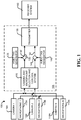
- Fig. 1 is an exemplary configuration of a transmitter system 105 of a videoconferencing system 100.
- the transmitter system 105 has a camera and microphone selection and control system 120, a video tag generator 125, a video signal combiner 130 which provides a video output signal 135, an audio tag generator 140, and an audio signal combiner 145 which provides an audio output signal 150.
- the video and audio output signals may be broadcast or transmitted by a transmitter 155.
- the control system 120 may also send signals, intended for remote systems, advising that it has an active speaker who should be given the larger panel if multiple panels are used to display multiple locations.
- the transmitter 155 may use any convenient means to send the video and audio output signals and any control signals to one or more receiver systems 160 at remote locations. It will be appreciated that there is a transmitter system 105 and a receiver system 160 at each location, and that the transmitter system 105 and receiver system 160 at a location may be combined into a single device.
- One or more cameras 110 (110A-110N) and one or more microphones 115 (115A-115N) provide video signals and audio signals, respectively, to the transmitter system 105 and, more particularly, to the control system 120, which has inputs for receiving these signals.
- the camera and microphone selection and control system 120 may select which camera 110 and which microphone 115 will be used to generate the local picture and sound, if more than one of either device is used, may control the pan, zoom, and/or tilt of the selected camera 110 if the camera can be so controlled, and may generate control or other signals for transmission to the remote systems.
- the video tag generator 125 and an audio tag generator 140 generate video and audio tags, respectively.
- a video signal combiner 130 manipulates or modifies the video pixels in the video stream to add the video tag and produces a tagged video signal 135.
- An audio signal combiner 145 manipulates or modifies bits in the audio stream to produce a tagged audio signal 150. This may be considered to be "tagging" a signal or adding a tag to a signal.
- the tag generators 125 and 140 may be embodied in a single device, the signal combiners 130, 145 may be embodied in a single device, and one to all of these components may be embodied as part of the control system 120.
- a video and/or audio stream is preferably modified using ways or only to levels which are subtle and/or undetectable to humans, but which can be detected by algorithmic analysis of the video or audio stream.
- a distortion level of less than a predetermined level may be imperceptible to a typical human observer. For example, modifying the least significant bit in a data word even if the tag was in every word would generally not be noticeable or objectionable.
- placing a video tag during a blanking interval or retrace period in a video frame, or placing a video tag at the corner of the bottom of the display may not be noticeable or objectionable. Even placing the video tag as the most significant bit may not be noticeable or objectionable if only on a single pixel during a frame.
- the video and/or audio stream may be modified by, for example, using the least significant bit or bits to convey information other than the initial audio or video signal. Such modification may be done every data word, every other data word, every Nth data word, every N milliseconds, before or after a synchronization word or bit, etc.
- the last bit(s) of the appropriate data word(s) may always have the same value, e.g., 0, 1,2, 3, etc., may alternate between values, may progress through values, etc.
- Other techniques may also be used to identify a data word, or part thereof, as a tag, or as identifying information associated with a tag or a videoconference. As another example, an entire data word may be used for this purpose.
- Video signals provide the opportunity to send even more information without noticeably degrading the quality of the video.
- Fig. 2 is an illustration of an exemplary videoconferencing system environment 200.
- Several persons 205 (205A-205C) are gathered around a table 210, which has thereupon a plurality of microphones 115 (115A-115E).
- a speaker 225 Also shown is a speaker 225.
- a transmitter system 105 which is connected to the cameras and microphones, and a receiver system 160 which is connected to the display and speaker.
- the transmitter system 105 and receiver system 160 may be, and typically are, embodied in a single device and are connected by a convenient transmission media to one or more remote videoconferencing systems.
- the control system 120 detects the signal from microphone 115B, switches to microphone 115B, switches to a camera 110B previously pointed toward the area of the person 115B, or points a camera 110B toward the area of the person 115B, and then transmits the audio signal from the microphone 115B and the video signal from the camera 115B to the remote location, possibly along with a signal indicating that person 205B should be prominently displayed on the remote screen.
- a camera is to pan, tilt, and/or zoom the camera to achieve a desired picture of a desired location.
- a sound-reflective object or surface 230 such as a mirror, picture, or window is present.
- the remote speaker 220 is talking and the voice of the remote speaker 220 is broadcast into the room by a speaker 225.
- the sound 235 of the remote speaker 220 bounces off the reflective surface 230 and arrives at the microphone 115D.
- the control system 120 detects the reflected voice 235 at microphone 115D and erroneously determines that there is a local person at microphone 115D who is speaking.
- the control system 120 then switches to the microphone 115D and points a camera 110 toward the empty space near microphone 115D.
- reflected sounds and echoes can cause problems during videoconferencing sessions. This may occur repeatedly until the remote person 220 quits speaking or someone turns down the volume of the speaker 225.
- the transmitter system 105 injects a tag(s) into the audio signal and/or video signal.
- the display 215 and the speaker 225 will then reproduce those tag(s) in their outputs.
- the control system 120 detects the reflected voice 235 at microphone 115D but also detects the tag in the reflected voice 235.
- the control system 120 determines that the sound is from the remote speaker, not a local speaker, and therefore takes no action with respect to the reflected voice.
- the control system 120 may in addition, inspect the output of the camera. If the video tag is present then the control system 120 determines that the sound is reflected sound, and therefore takes no action with respect to the reflected voice.
- the microphone 115B detects the voice of the local person 205B, but an audio tag is not present.
- the control system 120 then correctly switches to microphone 115B and directs a camera 110 toward the local person 205B, and a video tag will not be present.
- the control system 120 correctly determines that the person 205B is speaking and takes appropriate action. It will be appreciated that some reflected sound 235 may appear at microphones 115B as well. The volume of the reflected sound 235 will, however, be significantly less than the volume of the voice of the local speaker 205B, so the reflected tag will be at too low a level to be detected by the control system 120.
- the tag volume will be below the level of the least significant bit(s).
- the reflected sound 235 may also be picked up by other microphones 115 as well, but the control system 120 will reject these microphones either because their volume is less than the volume at microphone 115B or because the tag will be readily detectable.
- the control system 120 will detect the tag in the audio signal picked up by the microphone 115A or 115E, determine that the voice is not that of a local speaker, and not switch to the microphone 115A or 115E.
- control system 120 may point the camera 240 toward the display 215, detect the video tag being emitted by the display 215, and then point the camera 240 back to its original direction or to a default direction.
- the audio and video tags enhance the videoconferencing experience by reducing or eliminating erroneous switching of the camera and/or microphone caused by the voice of the remote speaker.
- the tags may also be used for identification of the videoconference, if desired.
- the tags may contain information regarding the company name, time, date, room location, transmitting equipment used such as but not limited to model, manufacturer, serial number, software version, trademark information, copyright information, confidentiality information, ownership information, protocol or standard used, etc. All of this information need not be transmitted, nor does all of the desired information need to be transmitted at once, repeatedly, or continuously. Rather, the bits which identify the tag as such need only be transmitted frequently enough that the control system 120 can recognize the tag as such. Thus, for example, as mentioned above, the bits which identify the tag as might only be transmitted every N data words, the other data words being used for the transmission of the information mentioned above.
- information contained in the tag(s) need not be obtained from the picture presented by the display 215 or from the sound presented by the speaker 225. Rather, and preferably, this information is obtained directly from the video and/or audio signals received by the receiver system 160.
- the data rate can be quite slow but, preferably, the identifiable part of the tag is preferably delivered repeatedly in less than half the hysteresis of the ASD delay.
- the identifiable part of the tag is even more preferably delivered more frequently so as to accommodate lost data due to interference during transmission or room noise.
- the speed of delivery of the additional information is less time sensitive and therefore can be transmitted over a longer period of time.
- Fig. 3 is a flowchart of an exemplary tag detection and camera and microphone control technique 300.
- a determination 310 is made as to whether any audio signal is above a threshold level. If not, a return is made to 310. If so, then a determination 315 is made as to whether a tag is present in that audio signal. If so, then that audio signal is ignored 317 and a return is made to 310. If not, then a camera is directed or pointed 320 toward the sound source identified by the audio signal. For example, if the audio signal is from microphone 115A then a camera 110 will be pointed toward the area serviced by microphone 115A, or a camera which has been previously pointed toward that area will be selected.
- a microphone is picking up sound and there is an audio tag embedded in that sound, or if a camera is directed toward the source of that sound is picking up a video tag embedded in the video signal, then the system will ignore that sound and leave the microphone and camera settings as they were. If, however, an embedded tag is not detected in either signal, then the microphone and/or camera will be selected for transmission of that sound and picture to the remote videoconferencing after insertion of a local tag into at least one of those signals. Thus, an active speaker is correctly selected while remote, reflected sounds are ignored.
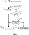
- Fig. 4 is a flowchart of an exemplary information recording technique 400. After starting 405, a determination is made 410 whether the session is to be recorded. If not then the procedure is ended 415. If so, then a determination is made 420 as to whether tags are present. If no tag is present then the session is recorded 430. If at least one tag is present then a determination is made 425 whether information is present in the tag(s). If not then the session is recorded 430. If so, then the session is recorded 435 with at least some of the information.
- the information to be recorded with the session may be all of the information included in the tag or may be only a preselected portion, such as the date and time.
- the logical operations described herein are implemented (1) as a sequence of computer implemented acts or program modules running on a computing system and/or (2) as interconnected machine logic circuits or circuit modules within the computing system. The implementation is a matter of choice dependent on the performance and other requirements of the computing system. Accordingly, the logical operations described herein are referred to variously as states operations, structural devices, acts, or modules. These operations, structural devices, acts and modules may be implemented in software, in firmware, in special purpose digital logic, and any combination thereof. It should also be appreciated that more or fewer operations may be performed than shown in the figures and described herein. These operations may also be performed in a different order than those described herein.
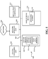
- Fig. 5 shows illustrative computer architecture for a computer 500 capable of executing the software components described herein for a videoconferencing system in the manner presented above.
- the computer architecture shown illustrates a conventional desktop, laptop, or server computer and may be utilized to execute any aspects of the software components presented herein described as executing on the client computer 104, the front-end server computers 106A-106N, or the back-end server computers 108A-108N.
- the computer architecture shown includes a central processing unit 502 ("CPU"), a system memory 508, including a random access memory 514 (“RAM”) and a read-only memory (“ROM”) 516, and a system bus 504 that couples the memory to the CPU 502.
- CPU central processing unit
- RAM random access memory
- ROM read-only memory
- the computer 500 further includes a mass storage device 510 for storing an operating system 518, application programs, and other program modules, which are described in greater detail herein.
- the mass storage device 510 is connected to the CPU 502 through a mass storage controller (not shown) connected to the bus 504.
- the mass storage device 510 and its associated computer-readable media provide non-volatile storage for the computer 500.
- computer-readable media can be any available computer storage media or communication media that can be accessed by the computer architecture 500.
- computer storage media may include volatile and non-volatile, removable and non-removable media implemented in any method or technology for storage of information such as computer-readable instructions, data structures, program modules or other data.
- computer storage media includes, but is not limited to, RAM, ROM, EPROM, EEPROM, flash memory or other solid state memory technology, CD-ROM, digital versatile disks ("DVD"), HD-DVD, BLU-RAY, or other optical storage, magnetic cassettes, magnetic tape, magnetic disk storage or other magnetic storage devices, or any other medium which can be used to store the desired information and which can be accessed by the computer 500.
- DVD digital versatile disks
- HD-DVD high definition digital versatile disks
- BLU-RAY blue ray
- magnetic cassettes magnetic tape
- magnetic disk storage magnetic disk storage devices
- Communication media includes computer readable instructions, data structures, program modules, or other data in a modulated data signal such as a carrier wave or other transport mechanism and includes any delivery media.
- modulated data signal means a signal that has one or more of its characteristics changed or set in a manner as to encode information in the signal.
- communication media includes wired media such as a wired network or direct-wired connection, and wireless media such as acoustic, RF, infrared and other wireless media. Combinations of the any of the above should also be included within the scope of computer-readable media.
- the computer 500 may operate in a networked environment using logical connections to remote computers through a network such as the network 520.
- the computer 500 may connect to the network 520 through a network interface unit 506 connected to the bus 504. It should be appreciated that the network interface unit 506 may also be utilized to connect to other types of networks and remote computer systems.
- the computer 500 may also include an input/output controller 512 for receiving and processing input from a number of other devices, including a keyboard, mouse, or electronic stylus. Similarly, an input/output controller may provide output to a display screen, a printer, or other type of output device.
- a number of program modules and data files may be stored in the mass storage device 510 and RAM 514 of the computer 500, including an operating system 518 suitable for controlling the operation of a networked desktop, laptop, or server computer.
- the mass storage device 510 and RAM 514 may also store one or more program modules which implement the various operations described above.
- the mass storage device 510 and the RAM 514 may also store other types of program modules.
- program modules include routines, programs, components, data structures, and other types of structures that perform particular tasks or implement particular abstract data types.
- program modules include routines, programs, components, data structures, and other types of structures that perform particular tasks or implement particular abstract data types.
- program modules include routines, programs, components, data structures, and other types of structures that perform particular tasks or implement particular abstract data types.
- the subject matter described herein may be practiced, if desired, with other computer system configurations, including hand-held devices, multiprocessor systems, microprocessor-based or programmable consumer electronics, minicomputers, mainframe computers, and the like.
Description
- Videoconferencing has become widespread and many offices have rooms especially configured for videoconferencing sessions. Such rooms typically contain video conferencing gear, such as one or more moveable cameras and one or more microphones, the microphones typically being placed at locations around a table in the room for participants. Active Speaker Detection (ASD) is frequently used to select a camera, or to move (pan and/or tilt) a camera to show the person in the room who is speaking and/or to select the microphone which will be active. When a remote person is speaking, their image and/or sound come out of an audio-video display, such as a television (TV), monitor, or other type of display, in the room. This may cause the ASD to erroneously select the image on the remote person on the TV who is talking rather than to select the last local person who is or was talking.
- Also, in multiple-location videoconferencing sessions, where three or more separate locations are in a single videoconferencing session, then, typically, several panels will be displayed, one panel being larger than the others and showing the person who is speaking, and the other panels showing a picture from a camera at the other locations. When erroneous ASD occurs, as mentioned above, the equipment in the room where a person is speaking will send a signal to the equipment at the other locations advising that the person at its location is speaking and so the main display should be from its camera. When this happens, the larger panel may switch from showing a person who is actually speaking to showing a picture of a TV screen or an empty chair. Thus, a problem with ASD is that if the sound from the remote videoconferencing system is reflected or is so loud that it triggers ASD then the remote sound may be retransmitted back to the remote system and/or cause the local camera to focus on an empty chair or the display screen showing the remote videoconferencing location.
- One technique that has been used to eliminate such erroneous ASD selection is to spot the image scan line tracing on the TV to determine that the sound is coming from a TV rather than a local person. High Definition TVs (HDTVs), however, have high (240Hz or better) progressive scan rates and image resolutions that are the equal of the cameras so image scan line tracing is of limited use when HDTV is involved. Additionally, ASD can often have trouble with sound echoing around a room. A sound reflective surface, such as window or a glass-covered picture, may reflect sound from the TV in a manner that the sound appears to originate from a local person at the table, even if there is not actually a person sitting at that position at the table. Further, if a recording is made of the videoconference, it is dependent upon a human to remember to accurately label the recording with at least, for example, the date of the videoconference. This is often forgotten and done later, sometimes with an erroneous or incomplete label. It is with respect to these considerations and others that the disclosure made herein is presented.
- Technologies are described herein for a videoconferencing system that selects an active speaker while avoiding erroneously selecting a microphone or camera that is picking up audio or video from a connected remote signal. In one implementation, a tag is added to an outgoing audio and/or video signal. If the microphone picks up a sound that contains the tag from the remote system then the sound is ignored and ASD is not implemented. If the sound does not contain the remote tag then the video from the local camera is inspected. If it contains a remote tag then ASD is not implemented. If a remote tag is not present in either signal then ASD is implemented.
- A transmitter system is defined in
claim 1. - A method for operating a transmitter of a videoconferencing is defined in claim 4.
- A computer storage as defined in claim 8.
- It should be appreciated that the above-described subject matter may also be implemented as a computer-controlled apparatus, a computer process, a computing system, or as an article of manufacture such as a computer-readable medium. These and various other features will be apparent from a reading of the following Detailed Description and a review of the associated drawings.
- This Summary is provided to introduce a selection of concepts in a simplified form that are further described below in the Detailed Description. This Summary is not intended to identify key features or essential features of the claimed subject matter, nor is it intended that this Summary be used to limit the scope of the claimed subject matter. Furthermore, the claimed subject matter is not limited to implementations that solve any or all disadvantages noted in any part of this disclosure.
-
-
Fig. 1 is an exemplary configuration of a transmitter system of a videoconferencing system. -
Fig. 2 is an illustration of an exemplary videoconferencing system environment. -
Fig. 3 is a flowchart showing an exemplary tag detection and camera and microphone control technique. -
Fig. 4 is a flowchart of an exemplary information recording technique. -
Fig. 5 is a computer architecture diagram showing an illustrative computer hardware and software architecture for a computing system capable of implementing aspects of the embodiments presented herein. - The following detailed description is directed to technologies for videoconferencing that may correctly select an active speaker while avoiding erroneously selecting a microphone or camera that is picking up audio or video from a connected remote signal. In the following detailed description, references are made to the accompanying drawings that form a part hereof, and which are shown by way of illustration specific embodiments or examples. Referring now to the drawings, in which like numerals represent like elements throughout the several figures, aspects of a computing system and methodology for videoconferencing will be described.
-
Fig. 1 is an exemplary configuration of atransmitter system 105 of avideoconferencing system 100. Thetransmitter system 105 has a camera and microphone selection andcontrol system 120, avideo tag generator 125, avideo signal combiner 130 which provides avideo output signal 135, anaudio tag generator 140, and an audio signal combiner 145 which provides anaudio output signal 150. The video and audio output signals may be broadcast or transmitted by atransmitter 155. Thecontrol system 120 may also send signals, intended for remote systems, advising that it has an active speaker who should be given the larger panel if multiple panels are used to display multiple locations. Thetransmitter 155 may use any convenient means to send the video and audio output signals and any control signals to one ormore receiver systems 160 at remote locations. It will be appreciated that there is atransmitter system 105 and areceiver system 160 at each location, and that thetransmitter system 105 andreceiver system 160 at a location may be combined into a single device. - One or more cameras 110 (110A-110N) and one or more microphones 115 (115A-115N) provide video signals and audio signals, respectively, to the
transmitter system 105 and, more particularly, to thecontrol system 120, which has inputs for receiving these signals. The camera and microphone selection andcontrol system 120 may select which camera 110 and which microphone 115 will be used to generate the local picture and sound, if more than one of either device is used, may control the pan, zoom, and/or tilt of the selected camera 110 if the camera can be so controlled, and may generate control or other signals for transmission to the remote systems. - The
video tag generator 125 and anaudio tag generator 140 generate video and audio tags, respectively. A video signal combiner 130 manipulates or modifies the video pixels in the video stream to add the video tag and produces a taggedvideo signal 135. An audio signal combiner 145 manipulates or modifies bits in the audio stream to produce a taggedaudio signal 150. This may be considered to be "tagging" a signal or adding a tag to a signal. Thetag generators control system 120. - A video and/or audio stream is preferably modified using ways or only to levels which are subtle and/or undetectable to humans, but which can be detected by algorithmic analysis of the video or audio stream. A distortion level of less than a predetermined level may be imperceptible to a typical human observer. For example, modifying the least significant bit in a data word even if the tag was in every word would generally not be noticeable or objectionable. As another example, placing a video tag during a blanking interval or retrace period in a video frame, or placing a video tag at the corner of the bottom of the display may not be noticeable or objectionable. Even placing the video tag as the most significant bit may not be noticeable or objectionable if only on a single pixel during a frame.
- The video and/or audio stream may be modified by, for example, using the least significant bit or bits to convey information other than the initial audio or video signal. Such modification may be done every data word, every other data word, every Nth data word, every N milliseconds, before or after a synchronization word or bit, etc. For example, the last bit(s) of the appropriate data word(s) may always have the same value, e.g., 0, 1,2, 3, etc., may alternate between values, may progress through values, etc. Other techniques may also be used to identify a data word, or part thereof, as a tag, or as identifying information associated with a tag or a videoconference. As another example, an entire data word may be used for this purpose. For example, if audio is sampled at a rate of 4000 samples/second, then using a limited number of these words to convey tag information would not noticeably degrade the quality of the audio. Video signals provide the opportunity to send even more information without noticeably degrading the quality of the video.
-
Fig. 2 is an illustration of an exemplaryvideoconferencing system environment 200. Several persons 205 (205A-205C) are gathered around a table 210, which has thereupon a plurality of microphones 115 (115A-115E). There is adisplay 215, which may be a TV, showing aremote person 220. Also shown is aspeaker 225. There is atransmitter system 105 which is connected to the cameras and microphones, and areceiver system 160 which is connected to the display and speaker. As mentioned, thetransmitter system 105 andreceiver system 160 may be, and typically are, embodied in a single device and are connected by a convenient transmission media to one or more remote videoconferencing systems. - When a local person speaks, such as
person 205B, thecontrol system 120 detects the signal frommicrophone 115B, switches tomicrophone 115B, switches to acamera 110B previously pointed toward the area of theperson 115B, or points acamera 110B toward the area of theperson 115B, and then transmits the audio signal from themicrophone 115B and the video signal from thecamera 115B to the remote location, possibly along with a signal indicating thatperson 205B should be prominently displayed on the remote screen. To point or to direct a camera, as used herein, is to pan, tilt, and/or zoom the camera to achieve a desired picture of a desired location. - Consider now the situation wherein a sound-reflective object or
surface 230, such as a mirror, picture, or window is present. Theremote speaker 220 is talking and the voice of theremote speaker 220 is broadcast into the room by aspeaker 225. Thesound 235 of theremote speaker 220 bounces off thereflective surface 230 and arrives at themicrophone 115D. Thecontrol system 120 detects the reflectedvoice 235 atmicrophone 115D and erroneously determines that there is a local person atmicrophone 115D who is speaking. Thecontrol system 120 then switches to themicrophone 115D and points a camera 110 toward the empty space nearmicrophone 115D. Thus, reflected sounds and echoes can cause problems during videoconferencing sessions. This may occur repeatedly until theremote person 220 quits speaking or someone turns down the volume of thespeaker 225. - To eliminate or at least reduce such erroneous ASD action, the
transmitter system 105 injects a tag(s) into the audio signal and/or video signal. Thedisplay 215 and thespeaker 225 will then reproduce those tag(s) in their outputs. Now, consider again the situation wherein theremote speaker 220 is talking and the voice of theremote speaker 220 is broadcast into the room by aspeaker 225. Thesound 235 of theremote speaker 220 bounces off thereflective surface 230 and arrives at themicrophone 115D. Thecontrol system 120 detects the reflectedvoice 235 atmicrophone 115D but also detects the tag in the reflectedvoice 235. Thecontrol system 120 then determines that the sound is from the remote speaker, not a local speaker, and therefore takes no action with respect to the reflected voice. - As another approach, when the reflected
voice 235 is present atmicrophone 115D, thecontrol system 120 may in addition, inspect the output of the camera. If the video tag is present then thecontrol system 120 determines that the sound is reflected sound, and therefore takes no action with respect to the reflected voice. - When, however, a
local person 205B speaks, themicrophone 115B detects the voice of thelocal person 205B, but an audio tag is not present. Thecontrol system 120 then correctly switches tomicrophone 115B and directs a camera 110 toward thelocal person 205B, and a video tag will not be present. Thus, thecontrol system 120 correctly determines that theperson 205B is speaking and takes appropriate action. It will be appreciated that somereflected sound 235 may appear atmicrophones 115B as well. The volume of the reflectedsound 235 will, however, be significantly less than the volume of the voice of thelocal speaker 205B, so the reflected tag will be at too low a level to be detected by thecontrol system 120. That is, when the sound from the microphone is digitized, the tag volume will be below the level of the least significant bit(s). The reflectedsound 235 may also be picked up by other microphones 115 as well, but thecontrol system 120 will reject these microphones either because their volume is less than the volume atmicrophone 115B or because the tag will be readily detectable. - It is possible, in some situations, that there will be a
camera 240 in the back of the room in addition to, or instead of, the cameras 110. Assume now that theremote person 220 is speaking and the sound emitted by thespeaker 225 is received by amicrophone camera 240 toward that location. Instead, with the tags used herein, thecontrol system 120 will detect the tag in the audio signal picked up by themicrophone microphone control system 120 may point thecamera 240 toward thedisplay 215, detect the video tag being emitted by thedisplay 215, and then point thecamera 240 back to its original direction or to a default direction. Thus, the audio and video tags enhance the videoconferencing experience by reducing or eliminating erroneous switching of the camera and/or microphone caused by the voice of the remote speaker. - The tags may also be used for identification of the videoconference, if desired. For example, the tags may contain information regarding the company name, time, date, room location, transmitting equipment used such as but not limited to model, manufacturer, serial number, software version, trademark information, copyright information, confidentiality information, ownership information, protocol or standard used, etc. All of this information need not be transmitted, nor does all of the desired information need to be transmitted at once, repeatedly, or continuously. Rather, the bits which identify the tag as such need only be transmitted frequently enough that the
control system 120 can recognize the tag as such. Thus, for example, as mentioned above, the bits which identify the tag as might only be transmitted every N data words, the other data words being used for the transmission of the information mentioned above. - In addition, information contained in the tag(s) need not be obtained from the picture presented by the
display 215 or from the sound presented by thespeaker 225. Rather, and preferably, this information is obtained directly from the video and/or audio signals received by thereceiver system 160. - The data rate can be quite slow but, preferably, the identifiable part of the tag is preferably delivered repeatedly in less than half the hysteresis of the ASD delay. The identifiable part of the tag is even more preferably delivered more frequently so as to accommodate lost data due to interference during transmission or room noise. The speed of delivery of the additional information is less time sensitive and therefore can be transmitted over a longer period of time.
-
Fig. 3 is a flowchart of an exemplary tag detection and camera andmicrophone control technique 300. After starting 305, adetermination 310 is made as to whether any audio signal is above a threshold level. If not, a return is made to 310. If so, then adetermination 315 is made as to whether a tag is present in that audio signal. If so, then that audio signal is ignored 317 and a return is made to 310. If not, then a camera is directed or pointed 320 toward the sound source identified by the audio signal. For example, if the audio signal is frommicrophone 115A then a camera 110 will be pointed toward the area serviced bymicrophone 115A, or a camera which has been previously pointed toward that area will be selected. - A determination is then made 325 as to whether a tag is present in the video signal from that camera. If so, then the camera is redirected 330 to its earlier position or the previous camera is selected. If not, then local tag(s) are inserted 335 into the audio signal and/or the video signal. The tagged signal(s) are then transmitted. A return is then made to 310.
- Thus, if a microphone is picking up sound and there is an audio tag embedded in that sound, or if a camera is directed toward the source of that sound is picking up a video tag embedded in the video signal, then the system will ignore that sound and leave the microphone and camera settings as they were. If, however, an embedded tag is not detected in either signal, then the microphone and/or camera will be selected for transmission of that sound and picture to the remote videoconferencing after insertion of a local tag into at least one of those signals. Thus, an active speaker is correctly selected while remote, reflected sounds are ignored.
-
Fig. 4 is a flowchart of an exemplaryinformation recording technique 400. After starting 405, a determination is made 410 whether the session is to be recorded. If not then the procedure is ended 415. If so, then a determination is made 420 as to whether tags are present. If no tag is present then the session is recorded 430. If at least one tag is present then a determination is made 425 whether information is present in the tag(s). If not then the session is recorded 430. If so, then the session is recorded 435 with at least some of the information. The information to be recorded with the session may be all of the information included in the tag or may be only a preselected portion, such as the date and time. - It should be appreciated that the logical operations described herein are implemented (1) as a sequence of computer implemented acts or program modules running on a computing system and/or (2) as interconnected machine logic circuits or circuit modules within the computing system. The implementation is a matter of choice dependent on the performance and other requirements of the computing system. Accordingly, the logical operations described herein are referred to variously as states operations, structural devices, acts, or modules. These operations, structural devices, acts and modules may be implemented in software, in firmware, in special purpose digital logic, and any combination thereof. It should also be appreciated that more or fewer operations may be performed than shown in the figures and described herein. These operations may also be performed in a different order than those described herein.
-
Fig. 5 shows illustrative computer architecture for acomputer 500 capable of executing the software components described herein for a videoconferencing system in the manner presented above. The computer architecture shown illustrates a conventional desktop, laptop, or server computer and may be utilized to execute any aspects of the software components presented herein described as executing on the client computer 104, the front-end server computers 106A-106N, or the back-end server computers 108A-108N. The computer architecture shown includes a central processing unit 502 ("CPU"), asystem memory 508, including a random access memory 514 ("RAM") and a read-only memory ("ROM") 516, and asystem bus 504 that couples the memory to theCPU 502. A basic input/output system containing the basic routines that help to transfer information between elements within thecomputer 500, such as during startup, is stored in theROM 516. Thecomputer 500 further includes amass storage device 510 for storing anoperating system 518, application programs, and other program modules, which are described in greater detail herein. - The
mass storage device 510 is connected to theCPU 502 through a mass storage controller (not shown) connected to thebus 504. Themass storage device 510 and its associated computer-readable media provide non-volatile storage for thecomputer 500. Although the description of computer-readable media contained herein refers to a mass storage device, such as a hard disk or CD-ROM drive, it should be appreciated by those skilled in the art that computer-readable media can be any available computer storage media or communication media that can be accessed by thecomputer architecture 500. - By way of example, and not limitation, computer storage media may include volatile and non-volatile, removable and non-removable media implemented in any method or technology for storage of information such as computer-readable instructions, data structures, program modules or other data. For example, computer storage media includes, but is not limited to, RAM, ROM, EPROM, EEPROM, flash memory or other solid state memory technology, CD-ROM, digital versatile disks ("DVD"), HD-DVD, BLU-RAY, or other optical storage, magnetic cassettes, magnetic tape, magnetic disk storage or other magnetic storage devices, or any other medium which can be used to store the desired information and which can be accessed by the
computer 500. For purposes of the claims, the phrase "computer storage medium," and variations thereof, does not include waves or signals per se and/or communication media. - Communication media includes computer readable instructions, data structures, program modules, or other data in a modulated data signal such as a carrier wave or other transport mechanism and includes any delivery media. The term "modulated data signal" means a signal that has one or more of its characteristics changed or set in a manner as to encode information in the signal. By way of example, and not limitation, communication media includes wired media such as a wired network or direct-wired connection, and wireless media such as acoustic, RF, infrared and other wireless media. Combinations of the any of the above should also be included within the scope of computer-readable media.
- According to various embodiments, the
computer 500 may operate in a networked environment using logical connections to remote computers through a network such as thenetwork 520. Thecomputer 500 may connect to thenetwork 520 through anetwork interface unit 506 connected to thebus 504. It should be appreciated that thenetwork interface unit 506 may also be utilized to connect to other types of networks and remote computer systems. Thecomputer 500 may also include an input/output controller 512 for receiving and processing input from a number of other devices, including a keyboard, mouse, or electronic stylus. Similarly, an input/output controller may provide output to a display screen, a printer, or other type of output device. - As mentioned briefly above, a number of program modules and data files may be stored in the
mass storage device 510 andRAM 514 of thecomputer 500, including anoperating system 518 suitable for controlling the operation of a networked desktop, laptop, or server computer. Themass storage device 510 andRAM 514 may also store one or more program modules which implement the various operations described above. Themass storage device 510 and theRAM 514 may also store other types of program modules. - While the subject matter described herein is presented in the general context of one or more program modules that execute in conjunction with the execution of an operating system and application programs on a computer system, those skilled in the art will recognize that other implementations may be performed in combination with other types of program modules. Generally, program modules include routines, programs, components, data structures, and other types of structures that perform particular tasks or implement particular abstract data types. Moreover, those skilled in the art will appreciate that the subject matter described herein may be practiced, if desired, with other computer system configurations, including hand-held devices, multiprocessor systems, microprocessor-based or programmable consumer electronics, minicomputers, mainframe computers, and the like.
- Based on the foregoing, it should be appreciated that technologies for videoconferencing are provided herein. Although the subject matter presented herein has been described in language specific to computer structural features, methodological and transformative acts, specific computing machinery, and computer readable media, it is to be understood that the invention defined in the appended claims is not necessarily limited to the specific features, acts, or media described herein. Rather, the specific features, acts and mediums are disclosed as example forms of implementing the claims.
- The subject matter described above is provided by way of illustration only and should not be construed as limiting. Various modifications and changes may be made to the subject matter described herein without following the example embodiments and applications illustrated and described, and without departing from the scope of the present invention, which is set forth in the following claims.
Claims (13)
- A transmitter system (105) for a videoconferencing system (100), comprising:a control system (120) arranged to determine if an audio tag is present in a received audio signal;a tag generator (125, 140) to generate an audio tag;a combiner (130, 145) to combine the received audio signal with the generated audio tag if it is determined that the received signal has no audio tag to produce a tagged audio signal (150) such that the audio tag is detectable in the tagged audio signal (150) to a control system of another video conferencing system; anda transmitter (155) to transmit the tagged audio signal (150) and a received video signal (135) as part of a videoconference.
- The transmitter system (105) of claim 1, wherein the control system (120) embeds additional information into the generated audio tag.
- The transmitter system (105) of any preceding claim, wherein the tag generator (125, 140) is further configured to generate a video tag, the combiner (130, 145) is further configured to combine the received video signal with the video tag to produce a tagged video signal (135) and wherein the transmitter (155) is further configured to transmit the tagged audio signal (150) and the tagged video signal (135).
- A method for operating a transmitter system (105) of a videoconferencing system (100), the method comprising:determining (315) if an audio tag is present in a received audio signal;receiving a video signal;generating an audio tag;combining (335) the received audio signal with the generated audio tag if it is determined that the received signal has no audio tag to produce a tagged audio signal (150) such that the audio tag is detectable in the tagged audio signal (150) to a control system of another video conferencing system; andtransmitting (340) the tagged audio signal and the video signal (135) as part of a video conference.
- The method of claim 4 wherein there are a plurality of audio signals and further comprising selecting an audio signal for transmission which does not contain an audio tag from another videoconferencing system.
- The method of claim 4 or 5, further comprising:generating a video tag;combining (335) the video signal with the generated video tag to produce a tagged video signal (135); andtransmitting (340) the tagged audio signal (150) and the tagged video signal (135).
- The method of claim 6 wherein there are a plurality of video signals and further comprising selecting a video signal for transmission which does not contain a video tag from another videoconferencing system.
- A computer storage medium having computer executable instructions stored thereon which, when executed by a computer, cause the computer to:determine (315) if an audio tag is present in a received audio signal;generate an audio tag;combine (335) a received audio signal with the generated audio tag if it is determined that the received signal has no audio tag to produce a tagged audio signal (150) such that the audio tag is detectable in the tagged audio signal (150) to a control system of another video conferencing system; andtransmit (340) the tagged audio signal (150) and a received video signal (135) as part of a video conference.
- The computer storage medium of claim 8 wherein the computer storage medium further comprises computer executable instructions stored thereon which, when executed by a computer, cause the computer to detect audio tags from a remote videoconferencing system in a plurality of received audio signals, and to select an audio signal which does not contain an audio tag for combination with the generated audio tag.
- The computer storage medium of claim 8 wherein the computer storage medium further comprises computer executable instructions stored thereon which, when executed by a computer, cause the computer to embed additional information into the generated audio tag.
- The computer storage medium claim of claim 8, wherein the computer storage medium further comprises computer executable instructions stored thereon which, when executed by a computer, cause the computer to:generate a video tag;combine (335) the video signal with the generated video tag to produce a tagged video signal (135); andtransmit (340) the tagged audio signal (150) and the tagged video signal (135).
- The computer storage medium of claim 11 wherein the computer storage medium further comprises computer executable instructions stored thereon which, when executed by a computer, cause the computer to detect video tags from a remote videoconferencing system in a plurality of received video signals, and to select a video signal which does not contain a video tag for combination with the generated video tag.
- The computer storage medium of claim 11 wherein the computer storage medium further comprises computer executable instructions stored thereon which, when executed by a computer, cause the computer to combine (335) the received audio signal with the audio tag to produce a tagged audio signal (150) in a manner wherein distortion in the tagged audio signal (150) is less than a predetermined level or combine (335) the received video signal with the video tag to produce a tagged video signal (135) wherein distortion in the tagged video signal (135) is less than a predetermined level.
Applications Claiming Priority (2)
| Application Number | Priority Date | Filing Date | Title |
|---|---|---|---|
| US13/719,314 US9065971B2 (en) | 2012-12-19 | 2012-12-19 | Video and audio tagging for active speaker detection |
| PCT/US2013/076671 WO2014100466A2 (en) | 2012-12-19 | 2013-12-19 | Video and audio tagging for active speaker detection |
Publications (2)
| Publication Number | Publication Date |
|---|---|
| EP2912841A2 EP2912841A2 (en) | 2015-09-02 |
| EP2912841B1 true EP2912841B1 (en) | 2020-10-28 |
Family
ID=49943568
Family Applications (1)
| Application Number | Title | Priority Date | Filing Date |
|---|---|---|---|
| EP13818933.7A Active EP2912841B1 (en) | 2012-12-19 | 2013-12-19 | Video and audio tagging for active speaker detection |
Country Status (11)
| Country | Link |
|---|---|
| US (1) | US9065971B2 (en) |
| EP (1) | EP2912841B1 (en) |
| JP (1) | JP6321033B2 (en) |
| KR (1) | KR102110632B1 (en) |
| CN (1) | CN104937926B (en) |
| AU (1) | AU2013361258B2 (en) |
| BR (1) | BR112015011758B1 (en) |
| CA (1) | CA2889706C (en) |
| MX (1) | MX352445B (en) |
| RU (1) | RU2632469C2 (en) |
| WO (1) | WO2014100466A2 (en) |
Families Citing this family (9)
| Publication number | Priority date | Publication date | Assignee | Title |
|---|---|---|---|---|
| US9065971B2 (en) * | 2012-12-19 | 2015-06-23 | Microsoft Technology Licensing, Llc | Video and audio tagging for active speaker detection |
| US20150281832A1 (en) * | 2014-03-28 | 2015-10-01 | Panasonic Intellectual Property Management Co., Ltd. | Sound processing apparatus, sound processing system and sound processing method |
| US9681097B1 (en) | 2016-01-20 | 2017-06-13 | Global Tel*Link Corporation | Secure video visitation system |
| US10296994B2 (en) | 2016-02-11 | 2019-05-21 | Global Tel*Link Corporation | System and method for visitation management in a controlled environment |
| US9558523B1 (en) | 2016-03-23 | 2017-01-31 | Global Tel* Link Corp. | Secure nonscheduled video visitation system |
| US10311219B2 (en) * | 2016-06-07 | 2019-06-04 | Vocalzoom Systems Ltd. | Device, system, and method of user authentication utilizing an optical microphone |
| JP6520878B2 (en) * | 2016-09-21 | 2019-05-29 | トヨタ自動車株式会社 | Voice acquisition system and voice acquisition method |
| KR20180093676A (en) | 2017-02-14 | 2018-08-22 | 한국전자통신연구원 | Apparatus and method for inserting tag to the stereo audio signal and extracting tag from the stereo audio signal |
| US11282537B2 (en) | 2017-06-09 | 2022-03-22 | International Business Machines Corporation | Active speaker detection in electronic meetings for providing video from one device to plurality of other devices |
Family Cites Families (41)
| Publication number | Priority date | Publication date | Assignee | Title |
|---|---|---|---|---|
| US5099319A (en) * | 1989-10-23 | 1992-03-24 | Esch Arthur G | Video information delivery method and apparatus |
| US5689641A (en) | 1993-10-01 | 1997-11-18 | Vicor, Inc. | Multimedia collaboration system arrangement for routing compressed AV signal through a participant site without decompressing the AV signal |
| AUPP392498A0 (en) * | 1998-06-04 | 1998-07-02 | Innes Corporation Pty Ltd | Traffic verification system |
| US7081915B1 (en) | 1998-06-17 | 2006-07-25 | Intel Corporation | Control of video conferencing using activity detection |
| US7062039B1 (en) * | 1999-05-27 | 2006-06-13 | Telefonaktiebolaget Lm Ericsson | Methods and apparatus for improving adaptive filter performance by inclusion of inaudible information |
| US6594629B1 (en) * | 1999-08-06 | 2003-07-15 | International Business Machines Corporation | Methods and apparatus for audio-visual speech detection and recognition |
| JP2002223422A (en) * | 2001-01-29 | 2002-08-09 | Nec Corp | Multi-point video conference controller and video packet transmission method |
| US7161939B2 (en) * | 2001-06-29 | 2007-01-09 | Ip Unity | Method and system for switching among independent packetized audio streams |
| KR100552468B1 (en) * | 2001-07-19 | 2006-02-15 | 삼성전자주식회사 | an electronic-apparatus and method for preventing mis-operation and rising speech recognition rate according to sound recognizing |
| US6749512B2 (en) * | 2002-03-15 | 2004-06-15 | Macgregor Brian | Computer network implemented gaming system and method of using same |
| EP1443498B1 (en) * | 2003-01-24 | 2008-03-19 | Sony Ericsson Mobile Communications AB | Noise reduction and audio-visual speech activity detection |
| GB2404297B (en) * | 2003-07-24 | 2007-12-05 | Hewlett Packard Development Co | Editing multiple camera outputs |
| JP4414708B2 (en) * | 2003-09-19 | 2010-02-10 | 株式会社リコー | Movie display personal computer, data display system, movie display method, movie display program, and recording medium |
| US7379875B2 (en) * | 2003-10-24 | 2008-05-27 | Microsoft Corporation | Systems and methods for generating audio thumbnails |
| US20050138674A1 (en) * | 2003-12-17 | 2005-06-23 | Quadrock Communications, Inc | System and method for integration and synchronization of interactive content with television content |
| US7563168B2 (en) * | 2004-02-13 | 2009-07-21 | Texas Instruments Incorporated | Audio effect rendering based on graphic polygons |
| GB2415639B (en) * | 2004-06-29 | 2008-09-17 | Sony Comp Entertainment Europe | Control of data processing |
| US7304585B2 (en) * | 2004-07-02 | 2007-12-04 | Nokia Corporation | Initiation of actions with compressed action language representations |
| US20060147063A1 (en) | 2004-12-22 | 2006-07-06 | Broadcom Corporation | Echo cancellation in telephones with multiple microphones |
| US7450752B2 (en) * | 2005-04-07 | 2008-11-11 | Hewlett-Packard Development Company, L.P. | System and method for automatic detection of the end of a video stream |
| US9300790B2 (en) * | 2005-06-24 | 2016-03-29 | Securus Technologies, Inc. | Multi-party conversation analyzer and logger |
| CN100596061C (en) * | 2006-01-12 | 2010-03-24 | 大连理工大学 | Method for watermarking small wave threshold digital audio multiple mesh based on blind source separation |
| CA2544459A1 (en) * | 2006-04-21 | 2007-10-21 | Evertz Microsystems Ltd. | Systems and methods for synchronizing audio and video data signals |
| US7688889B2 (en) * | 2006-09-18 | 2010-03-30 | Rgb Networks, Inc. | Methods, apparatus, and systems for insertion of overlay content into a video signal with transrating capabilities |
| US8087044B2 (en) * | 2006-09-18 | 2011-12-27 | Rgb Networks, Inc. | Methods, apparatus, and systems for managing the insertion of overlay content into a video signal |
| US20080136623A1 (en) * | 2006-12-06 | 2008-06-12 | Russell Calvarese | Audio trigger for mobile devices |
| WO2008102283A1 (en) * | 2007-02-20 | 2008-08-28 | Nxp B.V. | Communication device for processing person associated pictures and video streams |
| US8385233B2 (en) * | 2007-06-12 | 2013-02-26 | Microsoft Corporation | Active speaker identification |
| US8300080B2 (en) * | 2007-06-29 | 2012-10-30 | Microsoft Corporation | Techniques for detecting a display device |
| US20090210789A1 (en) | 2008-02-14 | 2009-08-20 | Microsoft Corporation | Techniques to generate a visual composition for a multimedia conference event |
| FR2952263B1 (en) * | 2009-10-29 | 2012-01-06 | Univ Paris Descartes | METHOD AND DEVICE FOR CANCELLATION OF ACOUSTIC ECHO BY AUDIO TATOO |
| US20110214143A1 (en) * | 2010-03-01 | 2011-09-01 | Rits Susan K | Mobile device application |
| US8713593B2 (en) * | 2010-03-01 | 2014-04-29 | Zazum, Inc. | Detection system and method for mobile device application |
| US8635066B2 (en) * | 2010-04-14 | 2014-01-21 | T-Mobile Usa, Inc. | Camera-assisted noise cancellation and speech recognition |
| US8468012B2 (en) * | 2010-05-26 | 2013-06-18 | Google Inc. | Acoustic model adaptation using geographic information |
| US8723914B2 (en) | 2010-11-19 | 2014-05-13 | Cisco Technology, Inc. | System and method for providing enhanced video processing in a network environment |
| US8589167B2 (en) * | 2011-05-11 | 2013-11-19 | Nuance Communications, Inc. | Speaker liveness detection |
| US20120321062A1 (en) * | 2011-06-17 | 2012-12-20 | Fitzsimmons Jeffrey E | Telephonic Conference Access System |
| CN102368816A (en) * | 2011-12-01 | 2012-03-07 | 中科芯集成电路股份有限公司 | Intelligent front end system of video conference |
| US8886011B2 (en) * | 2012-12-07 | 2014-11-11 | Cisco Technology, Inc. | System and method for question detection based video segmentation, search and collaboration in a video processing environment |
| US9065971B2 (en) * | 2012-12-19 | 2015-06-23 | Microsoft Technology Licensing, Llc | Video and audio tagging for active speaker detection |
-
2012
- 2012-12-19 US US13/719,314 patent/US9065971B2/en active Active
-
2013
- 2013-12-19 EP EP13818933.7A patent/EP2912841B1/en active Active
- 2013-12-19 KR KR1020157016315A patent/KR102110632B1/en active IP Right Grant
- 2013-12-19 CA CA2889706A patent/CA2889706C/en active Active
- 2013-12-19 MX MX2015008119A patent/MX352445B/en active IP Right Grant
- 2013-12-19 RU RU2015123696A patent/RU2632469C2/en active
- 2013-12-19 CN CN201380066894.8A patent/CN104937926B/en active Active
- 2013-12-19 WO PCT/US2013/076671 patent/WO2014100466A2/en active Application Filing
- 2013-12-19 AU AU2013361258A patent/AU2013361258B2/en active Active
- 2013-12-19 BR BR112015011758-9A patent/BR112015011758B1/en active IP Right Grant
- 2013-12-19 JP JP2015549731A patent/JP6321033B2/en active Active
Non-Patent Citations (1)
| Title |
|---|
| None * |
Also Published As
| Publication number | Publication date |
|---|---|
| CN104937926A (en) | 2015-09-23 |
| WO2014100466A2 (en) | 2014-06-26 |
| AU2013361258B2 (en) | 2017-03-09 |
| MX2015008119A (en) | 2016-04-25 |
| RU2015123696A (en) | 2017-01-10 |
| KR102110632B1 (en) | 2020-05-13 |
| WO2014100466A3 (en) | 2014-08-07 |
| US9065971B2 (en) | 2015-06-23 |
| RU2632469C2 (en) | 2017-10-05 |
| AU2013361258A1 (en) | 2015-05-14 |
| EP2912841A2 (en) | 2015-09-02 |
| KR20150096419A (en) | 2015-08-24 |
| JP6321033B2 (en) | 2018-05-09 |
| BR112015011758B1 (en) | 2023-04-18 |
| BR112015011758A2 (en) | 2017-07-11 |
| CA2889706C (en) | 2020-04-28 |
| US20140168352A1 (en) | 2014-06-19 |
| CN104937926B (en) | 2018-05-25 |
| MX352445B (en) | 2017-11-24 |
| CA2889706A1 (en) | 2014-06-26 |
| JP2016506670A (en) | 2016-03-03 |
Similar Documents
| Publication | Publication Date | Title |
|---|---|---|
| EP2912841B1 (en) | Video and audio tagging for active speaker detection | |
| US7808521B2 (en) | Multimedia conference recording and manipulation interface | |
| US20100199187A1 (en) | Instant data sharing system and machine readable medium thereof | |
| US20170070702A1 (en) | Video conference audio/video verification | |
| US20110052136A1 (en) | Pattern-based monitoring of media synchronization | |
| US10032475B2 (en) | Enhancing an audio recording | |
| KR20100028060A (en) | Techniques for detecting a display device | |
| US20140196094A1 (en) | Method and apparatus for automatically switching channels | |
| WO2021204139A1 (en) | Video displaying method, device, equipment, and storage medium | |
| US10142583B1 (en) | Computing system with external speaker detection feature | |
| US20130100152A1 (en) | Method and apparatus for processing image display | |
| CN113132670A (en) | Video conference system | |
| CN112822435A (en) | Security method, device and system allowing user to easily access | |
| JP2020058014A (en) | Video processing apparatus, video conference system, video processing method, and program | |
| US10762913B2 (en) | Image-based techniques for audio content | |
| US9456180B2 (en) | Image processing apparatus, communication system, and computer program | |
| CN113132671A (en) | Video conference system | |
| EP3985989A1 (en) | Detection of modification of an item of content | |
| US11165989B2 (en) | Gesture and prominence in video conferencing | |
| JP7087779B2 (en) | Terminal devices, conference systems, terminal device control methods, and programs | |
| US8943247B1 (en) | Media sink device input identification | |
| CN109831703B (en) | Motion compensation method and device for HDMI signal | |
| US11895041B2 (en) | Establishing network presence | |
| US20130007351A1 (en) | Information processor, information processing method, and computer program product | |
| CN113489921A (en) | Video image display control method, device and system |
Legal Events
| Date | Code | Title | Description |
|---|---|---|---|
| PUAI | Public reference made under article 153(3) epc to a published international application that has entered the european phase |
Free format text: ORIGINAL CODE: 0009012 |
|
| 17P | Request for examination filed |
Effective date: 20150528 |
|
| AK | Designated contracting states |
Kind code of ref document: A2 Designated state(s): AL AT BE BG CH CY CZ DE DK EE ES FI FR GB GR HR HU IE IS IT LI LT LU LV MC MK MT NL NO PL PT RO RS SE SI SK SM TR |
|
| AX | Request for extension of the european patent |
Extension state: BA ME |
|
| DAX | Request for extension of the european patent (deleted) | ||
| STAA | Information on the status of an ep patent application or granted ep patent |
Free format text: STATUS: EXAMINATION IS IN PROGRESS |
|
| 17Q | First examination report despatched |
Effective date: 20181128 |
|
| REG | Reference to a national code |
Ref country code: DE Ref legal event code: R079 Ref document number: 602013073652 Country of ref document: DE Free format text: PREVIOUS MAIN CLASS: H04N0007150000 Ipc: H04N0007140000 |
|
| GRAP | Despatch of communication of intention to grant a patent |
Free format text: ORIGINAL CODE: EPIDOSNIGR1 |
|
| STAA | Information on the status of an ep patent application or granted ep patent |
Free format text: STATUS: GRANT OF PATENT IS INTENDED |
|
| RIC1 | Information provided on ipc code assigned before grant |
Ipc: H04N 7/14 20060101AFI20200424BHEP |
|
| INTG | Intention to grant announced |
Effective date: 20200515 |
|
| RIN1 | Information on inventor provided before grant (corrected) |
Inventor name: VERTHEIN, WILLIAM GEORGE Inventor name: LEORIN, SIMONE |
|
| GRAS | Grant fee paid |
Free format text: ORIGINAL CODE: EPIDOSNIGR3 |
|
| GRAJ | Information related to disapproval of communication of intention to grant by the applicant or resumption of examination proceedings by the epo deleted |
Free format text: ORIGINAL CODE: EPIDOSDIGR1 |
|
| GRAL | Information related to payment of fee for publishing/printing deleted |
Free format text: ORIGINAL CODE: EPIDOSDIGR3 |
|
| STAA | Information on the status of an ep patent application or granted ep patent |
Free format text: STATUS: EXAMINATION IS IN PROGRESS |
|
| GRAR | Information related to intention to grant a patent recorded |
Free format text: ORIGINAL CODE: EPIDOSNIGR71 |
|
| STAA | Information on the status of an ep patent application or granted ep patent |
Free format text: STATUS: GRANT OF PATENT IS INTENDED |
|
| GRAA | (expected) grant |
Free format text: ORIGINAL CODE: 0009210 |
|
| STAA | Information on the status of an ep patent application or granted ep patent |
Free format text: STATUS: THE PATENT HAS BEEN GRANTED |
|
| INTC | Intention to grant announced (deleted) | ||
| AK | Designated contracting states |
Kind code of ref document: B1 Designated state(s): AL AT BE BG CH CY CZ DE DK EE ES FI FR GB GR HR HU IE IS IT LI LT LU LV MC MK MT NL NO PL PT RO RS SE SI SK SM TR |
|
| INTG | Intention to grant announced |
Effective date: 20200922 |
|
| REG | Reference to a national code |
Ref country code: GB Ref legal event code: FG4D |
|
| REG | Reference to a national code |
Ref country code: CH Ref legal event code: EP |
|
| REG | Reference to a national code |
Ref country code: DE Ref legal event code: R096 Ref document number: 602013073652 Country of ref document: DE |
|
| REG | Reference to a national code |
Ref country code: AT Ref legal event code: REF Ref document number: 1329430 Country of ref document: AT Kind code of ref document: T Effective date: 20201115 |
|
| REG | Reference to a national code |
Ref country code: IE Ref legal event code: FG4D |
|
| REG | Reference to a national code |
Ref country code: AT Ref legal event code: MK05 Ref document number: 1329430 Country of ref document: AT Kind code of ref document: T Effective date: 20201028 |
|
| REG | Reference to a national code |
Ref country code: NL Ref legal event code: MP Effective date: 20201028 |
|
| PG25 | Lapsed in a contracting state [announced via postgrant information from national office to epo] |
Ref country code: FI Free format text: LAPSE BECAUSE OF FAILURE TO SUBMIT A TRANSLATION OF THE DESCRIPTION OR TO PAY THE FEE WITHIN THE PRESCRIBED TIME-LIMIT Effective date: 20201028 Ref country code: RS Free format text: LAPSE BECAUSE OF FAILURE TO SUBMIT A TRANSLATION OF THE DESCRIPTION OR TO PAY THE FEE WITHIN THE PRESCRIBED TIME-LIMIT Effective date: 20201028 Ref country code: PT Free format text: LAPSE BECAUSE OF FAILURE TO SUBMIT A TRANSLATION OF THE DESCRIPTION OR TO PAY THE FEE WITHIN THE PRESCRIBED TIME-LIMIT Effective date: 20210301 Ref country code: NL Free format text: LAPSE BECAUSE OF FAILURE TO SUBMIT A TRANSLATION OF THE DESCRIPTION OR TO PAY THE FEE WITHIN THE PRESCRIBED TIME-LIMIT Effective date: 20201028 Ref country code: NO Free format text: LAPSE BECAUSE OF FAILURE TO SUBMIT A TRANSLATION OF THE DESCRIPTION OR TO PAY THE FEE WITHIN THE PRESCRIBED TIME-LIMIT Effective date: 20210128 Ref country code: GR Free format text: LAPSE BECAUSE OF FAILURE TO SUBMIT A TRANSLATION OF THE DESCRIPTION OR TO PAY THE FEE WITHIN THE PRESCRIBED TIME-LIMIT Effective date: 20210129 |
|
| REG | Reference to a national code |
Ref country code: LT Ref legal event code: MG4D |
|
| PG25 | Lapsed in a contracting state [announced via postgrant information from national office to epo] |
Ref country code: ES Free format text: LAPSE BECAUSE OF FAILURE TO SUBMIT A TRANSLATION OF THE DESCRIPTION OR TO PAY THE FEE WITHIN THE PRESCRIBED TIME-LIMIT Effective date: 20201028 Ref country code: AT Free format text: LAPSE BECAUSE OF FAILURE TO SUBMIT A TRANSLATION OF THE DESCRIPTION OR TO PAY THE FEE WITHIN THE PRESCRIBED TIME-LIMIT Effective date: 20201028 Ref country code: BG Free format text: LAPSE BECAUSE OF FAILURE TO SUBMIT A TRANSLATION OF THE DESCRIPTION OR TO PAY THE FEE WITHIN THE PRESCRIBED TIME-LIMIT Effective date: 20210128 Ref country code: SE Free format text: LAPSE BECAUSE OF FAILURE TO SUBMIT A TRANSLATION OF THE DESCRIPTION OR TO PAY THE FEE WITHIN THE PRESCRIBED TIME-LIMIT Effective date: 20201028 Ref country code: LV Free format text: LAPSE BECAUSE OF FAILURE TO SUBMIT A TRANSLATION OF THE DESCRIPTION OR TO PAY THE FEE WITHIN THE PRESCRIBED TIME-LIMIT Effective date: 20201028 Ref country code: IS Free format text: LAPSE BECAUSE OF FAILURE TO SUBMIT A TRANSLATION OF THE DESCRIPTION OR TO PAY THE FEE WITHIN THE PRESCRIBED TIME-LIMIT Effective date: 20210228 Ref country code: PL Free format text: LAPSE BECAUSE OF FAILURE TO SUBMIT A TRANSLATION OF THE DESCRIPTION OR TO PAY THE FEE WITHIN THE PRESCRIBED TIME-LIMIT Effective date: 20201028 |
|
| PG25 | Lapsed in a contracting state [announced via postgrant information from national office to epo] |
Ref country code: HR Free format text: LAPSE BECAUSE OF FAILURE TO SUBMIT A TRANSLATION OF THE DESCRIPTION OR TO PAY THE FEE WITHIN THE PRESCRIBED TIME-LIMIT Effective date: 20201028 |
|
| REG | Reference to a national code |
Ref country code: DE Ref legal event code: R097 Ref document number: 602013073652 Country of ref document: DE |
|
| PG25 | Lapsed in a contracting state [announced via postgrant information from national office to epo] |
Ref country code: RO Free format text: LAPSE BECAUSE OF FAILURE TO SUBMIT A TRANSLATION OF THE DESCRIPTION OR TO PAY THE FEE WITHIN THE PRESCRIBED TIME-LIMIT Effective date: 20201028 Ref country code: SK Free format text: LAPSE BECAUSE OF FAILURE TO SUBMIT A TRANSLATION OF THE DESCRIPTION OR TO PAY THE FEE WITHIN THE PRESCRIBED TIME-LIMIT Effective date: 20201028 Ref country code: LT Free format text: LAPSE BECAUSE OF FAILURE TO SUBMIT A TRANSLATION OF THE DESCRIPTION OR TO PAY THE FEE WITHIN THE PRESCRIBED TIME-LIMIT Effective date: 20201028 Ref country code: SM Free format text: LAPSE BECAUSE OF FAILURE TO SUBMIT A TRANSLATION OF THE DESCRIPTION OR TO PAY THE FEE WITHIN THE PRESCRIBED TIME-LIMIT Effective date: 20201028 Ref country code: CZ Free format text: LAPSE BECAUSE OF FAILURE TO SUBMIT A TRANSLATION OF THE DESCRIPTION OR TO PAY THE FEE WITHIN THE PRESCRIBED TIME-LIMIT Effective date: 20201028 Ref country code: EE Free format text: LAPSE BECAUSE OF FAILURE TO SUBMIT A TRANSLATION OF THE DESCRIPTION OR TO PAY THE FEE WITHIN THE PRESCRIBED TIME-LIMIT Effective date: 20201028 |
|
| REG | Reference to a national code |
Ref country code: CH Ref legal event code: PL |
|
| PG25 | Lapsed in a contracting state [announced via postgrant information from national office to epo] |
Ref country code: DK Free format text: LAPSE BECAUSE OF FAILURE TO SUBMIT A TRANSLATION OF THE DESCRIPTION OR TO PAY THE FEE WITHIN THE PRESCRIBED TIME-LIMIT Effective date: 20201028 Ref country code: MC Free format text: LAPSE BECAUSE OF FAILURE TO SUBMIT A TRANSLATION OF THE DESCRIPTION OR TO PAY THE FEE WITHIN THE PRESCRIBED TIME-LIMIT Effective date: 20201028 |
|
| PLBE | No opposition filed within time limit |
Free format text: ORIGINAL CODE: 0009261 |
|
| REG | Reference to a national code |
Ref country code: BE Ref legal event code: MM Effective date: 20201231 |
|
| STAA | Information on the status of an ep patent application or granted ep patent |
Free format text: STATUS: NO OPPOSITION FILED WITHIN TIME LIMIT |
|
| 26N | No opposition filed |
Effective date: 20210729 |
|
| PG25 | Lapsed in a contracting state [announced via postgrant information from national office to epo] |
Ref country code: AL Free format text: LAPSE BECAUSE OF FAILURE TO SUBMIT A TRANSLATION OF THE DESCRIPTION OR TO PAY THE FEE WITHIN THE PRESCRIBED TIME-LIMIT Effective date: 20201028 Ref country code: LU Free format text: LAPSE BECAUSE OF NON-PAYMENT OF DUE FEES Effective date: 20201219 Ref country code: IT Free format text: LAPSE BECAUSE OF FAILURE TO SUBMIT A TRANSLATION OF THE DESCRIPTION OR TO PAY THE FEE WITHIN THE PRESCRIBED TIME-LIMIT Effective date: 20201028 Ref country code: IE Free format text: LAPSE BECAUSE OF NON-PAYMENT OF DUE FEES Effective date: 20201219 |
|
| PG25 | Lapsed in a contracting state [announced via postgrant information from national office to epo] |
Ref country code: LI Free format text: LAPSE BECAUSE OF NON-PAYMENT OF DUE FEES Effective date: 20201231 Ref country code: SI Free format text: LAPSE BECAUSE OF FAILURE TO SUBMIT A TRANSLATION OF THE DESCRIPTION OR TO PAY THE FEE WITHIN THE PRESCRIBED TIME-LIMIT Effective date: 20201028 Ref country code: CH Free format text: LAPSE BECAUSE OF NON-PAYMENT OF DUE FEES Effective date: 20201231 |
|
| PG25 | Lapsed in a contracting state [announced via postgrant information from national office to epo] |
Ref country code: IS Free format text: LAPSE BECAUSE OF FAILURE TO SUBMIT A TRANSLATION OF THE DESCRIPTION OR TO PAY THE FEE WITHIN THE PRESCRIBED TIME-LIMIT Effective date: 20210228 Ref country code: TR Free format text: LAPSE BECAUSE OF FAILURE TO SUBMIT A TRANSLATION OF THE DESCRIPTION OR TO PAY THE FEE WITHIN THE PRESCRIBED TIME-LIMIT Effective date: 20201028 Ref country code: MT Free format text: LAPSE BECAUSE OF FAILURE TO SUBMIT A TRANSLATION OF THE DESCRIPTION OR TO PAY THE FEE WITHIN THE PRESCRIBED TIME-LIMIT Effective date: 20201028 Ref country code: CY Free format text: LAPSE BECAUSE OF FAILURE TO SUBMIT A TRANSLATION OF THE DESCRIPTION OR TO PAY THE FEE WITHIN THE PRESCRIBED TIME-LIMIT Effective date: 20201028 |
|
| PG25 | Lapsed in a contracting state [announced via postgrant information from national office to epo] |
Ref country code: MK Free format text: LAPSE BECAUSE OF FAILURE TO SUBMIT A TRANSLATION OF THE DESCRIPTION OR TO PAY THE FEE WITHIN THE PRESCRIBED TIME-LIMIT Effective date: 20201028 |
|
| PG25 | Lapsed in a contracting state [announced via postgrant information from national office to epo] |
Ref country code: BE Free format text: LAPSE BECAUSE OF NON-PAYMENT OF DUE FEES Effective date: 20201231 |
|
| P01 | Opt-out of the competence of the unified patent court (upc) registered |
Effective date: 20230519 |
|
| PGFP | Annual fee paid to national office [announced via postgrant information from national office to epo] |
Ref country code: GB Payment date: 20231121 Year of fee payment: 11 |
|
| PGFP | Annual fee paid to national office [announced via postgrant information from national office to epo] |
Ref country code: FR Payment date: 20231122 Year of fee payment: 11 Ref country code: DE Payment date: 20231121 Year of fee payment: 11 |