EP2912839B1 - Method for providing contents and a digital device for the same - Google Patents
Method for providing contents and a digital device for the same Download PDFInfo
- Publication number
- EP2912839B1 EP2912839B1 EP13849678.1A EP13849678A EP2912839B1 EP 2912839 B1 EP2912839 B1 EP 2912839B1 EP 13849678 A EP13849678 A EP 13849678A EP 2912839 B1 EP2912839 B1 EP 2912839B1
- Authority
- EP
- European Patent Office
- Prior art keywords
- information
- digital device
- image data
- contents
- virtual
- Prior art date
- Legal status (The legal status is an assumption and is not a legal conclusion. Google has not performed a legal analysis and makes no representation as to the accuracy of the status listed.)
- Active
Links
Images


Classifications
-
- G—PHYSICS
- G06—COMPUTING; CALCULATING OR COUNTING
- G06T—IMAGE DATA PROCESSING OR GENERATION, IN GENERAL
- G06T15/00—3D [Three Dimensional] image rendering
-
- G—PHYSICS
- G09—EDUCATION; CRYPTOGRAPHY; DISPLAY; ADVERTISING; SEALS
- G09G—ARRANGEMENTS OR CIRCUITS FOR CONTROL OF INDICATING DEVICES USING STATIC MEANS TO PRESENT VARIABLE INFORMATION
- G09G5/00—Control arrangements or circuits for visual indicators common to cathode-ray tube indicators and other visual indicators
- G09G5/36—Control arrangements or circuits for visual indicators common to cathode-ray tube indicators and other visual indicators characterised by the display of a graphic pattern, e.g. using an all-points-addressable [APA] memory
- G09G5/37—Details of the operation on graphic patterns
- G09G5/377—Details of the operation on graphic patterns for mixing or overlaying two or more graphic patterns
-
- G—PHYSICS
- G06—COMPUTING; CALCULATING OR COUNTING
- G06F—ELECTRIC DIGITAL DATA PROCESSING
- G06F3/00—Input arrangements for transferring data to be processed into a form capable of being handled by the computer; Output arrangements for transferring data from processing unit to output unit, e.g. interface arrangements
- G06F3/14—Digital output to display device ; Cooperation and interconnection of the display device with other functional units
- G06F3/147—Digital output to display device ; Cooperation and interconnection of the display device with other functional units using display panels
-
- G—PHYSICS
- G09—EDUCATION; CRYPTOGRAPHY; DISPLAY; ADVERTISING; SEALS
- G09G—ARRANGEMENTS OR CIRCUITS FOR CONTROL OF INDICATING DEVICES USING STATIC MEANS TO PRESENT VARIABLE INFORMATION
- G09G3/00—Control arrangements or circuits, of interest only in connection with visual indicators other than cathode-ray tubes
- G09G3/001—Control arrangements or circuits, of interest only in connection with visual indicators other than cathode-ray tubes using specific devices not provided for in groups G09G3/02 - G09G3/36, e.g. using an intermediate record carrier such as a film slide; Projection systems; Display of non-alphanumerical information, solely or in combination with alphanumerical information, e.g. digital display on projected diapositive as background
-
- H—ELECTRICITY
- H04—ELECTRIC COMMUNICATION TECHNIQUE
- H04N—PICTORIAL COMMUNICATION, e.g. TELEVISION
- H04N5/00—Details of television systems
- H04N5/222—Studio circuitry; Studio devices; Studio equipment
- H04N5/262—Studio circuits, e.g. for mixing, switching-over, change of character of image, other special effects ; Cameras specially adapted for the electronic generation of special effects
-
- G—PHYSICS
- G09—EDUCATION; CRYPTOGRAPHY; DISPLAY; ADVERTISING; SEALS
- G09G—ARRANGEMENTS OR CIRCUITS FOR CONTROL OF INDICATING DEVICES USING STATIC MEANS TO PRESENT VARIABLE INFORMATION
- G09G5/00—Control arrangements or circuits for visual indicators common to cathode-ray tube indicators and other visual indicators
- G09G5/34—Control arrangements or circuits for visual indicators common to cathode-ray tube indicators and other visual indicators for rolling or scrolling
Definitions
- the present invention relates to a method for providing contents and a digital device for the same, and more particularly, to a method for providing contents and a digital device for the same, in which image data included in contents are displayed and navigated together with augmented reality information surrounded by a point where the corresponding image data are recorded.
- Augmented reality is the technology that displays image or background of reality together with virtual information. Unlike the virtual reality technology in which object, background and environment are provided as virtual images, the augmented reality technology provides a user with realer additional information than the actual environment by mixing a virtual object with an actual environment. For example, if the user illuminates surroundings of the road through a camera of a digital device while walking the road, information on buildings and road information included in images collected in the camera may be provided to the user. This augmented reality technology has received much more attention as a portable device has been recently spread.
- US 2009/0278948 A1 discloses a method of presenting information, capable of displaying an image including one or more objects being in the vicinity of the ground.
- the method includes the steps of: acquiring viewpoint information; acquiring visual line information; acquiring posture information; acquiring additional information related to the object position information; calculating horizon line information in the image; determining a reference line on the image on the basis of the horizon line information and the posture information; calculating distance information from the viewpoint position to the object; determining a display attribute of the additional information including a display mode of the additional information and a display position of the additional information in the image with respect to the reference line; and presenting the additional information on the basis of the display mode so as to reveal a relationship between the additional information and the object when displaying the image on the display unit.
- US 2011/0193985 A1 discloses an imaging device having an imaging portion that images a subject; a positional information acquisition portion that acquires positional information of an imaging position; a control portion which acquires information on the subject based on the positional information, and displays image data of the subject and the information on the subject on a display portion; and a hold control portion that outputs a hold control signal, which holds the image data of the subject and the information on the subject, to the control portion.
- the present invention is directed to a method for providing contents and a digital device for the same, which substantially obviate one or more problems due to limitations and disadvantages of the related art.
- An object of the present invention is to provide a method for providing contents and a digital device for the same in which image data are displayed through a digital device together with augmented reality information of an object included in the corresponding image data.
- Another object of the present invention is to provide a method for providing contents and a digital device for the same in which image data are navigated through a digital device together with augmented reality information surrounded by a point where the image data are recorded.
- the digital device may display image data together with augmented reality information associated with the image data.
- augmented reality information associated with the image data.
- augmented reality information surrounded by a point where image data are recorded is provided on the basis of direction change of the current digital device that displays the image data. Accordingly, the user may navigate the augmented reality information as if he/she is located in the place where the corresponding image data are recorded.
- augmented reality information in the corresponding point may be received in real time by using position information of a recording device when the image data are recorded. Accordingly, the user may receive the latest augmented reality information surrounded by the corresponding point through the digital device.
- the present invention is intended to display image data through a digital device together with virtual information of objects included in the corresponding image data. Also, the present invention is to provide a method for navigating virtual information of image data displayed through a digital device and virtual information of a zone surrounded by a point where the corresponding image data are recorded.
- the virtual information includes augmented reality information on a specific object.
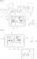
- FIG. 1 is a diagram illustrating that a recording device 200 records image data 10.
- the recording device 200 may record contents, which include image data 10, by using a camera unit (not shown). At this time, examples of the contents recorded by the recording device 200 may include photos, moving pictures, and still images. Also, various types of contents including at least one image data 10 may be recorded by the recording device 200. A user may record images of various types of objects such as a specific building and specific road by using the recording device 200. The image data 10 are generated through the recorded images.
- virtual information 20a and 20b corresponding to at least one object included in the image data 10 may exist in the at least one object.
- the virtual information 20a and 20b includes augmented reality information included in the image data 10.
- the virtual information 20a and 20b may include various kinds of information such as name, type of business and business hours on a specific store on the image data 10. If the recording device 200 provides an augmented reality function, the virtual information 20a and 20b may be displayed on a display unit 220 of the recording device 200 together with the image data 10. The recording device 200 may record the virtual information 20a and 20b of the object included in the image data 10 when recording the image data 10.
- the recording device 200 detects position information P of the corresponding recording device 200 when recording the image data 10.
- the position information P of the recording device 200 may be the position information of the point where the recording device 200 is located on a global positioning system (GPS).
- GPS global positioning system
- the recording device 200 may detect the position information P by using a GPS receiving device.
- the recording device 200 may indirectly detect its position information P through a network connected therewith.
- the recording device 200 detects direction information ( ⁇ , 0) together with the image data 10 when recording the image data 10.
- the direction information ( ⁇ , 0) of the recording device 200 includes at least one of panning angle information and tilting angle information of the recording device 200.
- the panning angle information and the tilting angle information represent an angle between the direction of the recording device 200 and a first reference direction.
- the direction of the recording device 200 may be set in various manners. For example, a recording direction of the camera unit of the recording device 200 may be set to the direction of the recording device 200.
- the first reference direction may be set to a specific orientation (for example, northern direction), altitude (for example, altitude 0°), or their combination.
- the recording device 200 may detect its panned angle on the basis of a specific orientation, that is, northern (N) direction. Also, the recording device may detect its tilting angle on the basis of a specific altitude, that is, altitude 0°.
- the recording device 200 has a panning angle of ⁇ and a tilting angle of 0° with reference to the first reference direction. Accordingly, in FIG. 1 , the direction information of the recording device 200 becomes ( ⁇ , 0).
- the recording device 200 may include at least one of a compass sensor and a gyroscope sensor, and may detect at least one of its panning angle information and tilting angle information by using a sensor provided therein.
- the first reference direction and the direction of the recording device 200 are only exemplary to describe a method for obtaining the direction information ( ⁇ , 0), and various modifications may be made in the first reference direction and the direction of the recording device 200.
- the recording device 200 stores the position information (P) and the direction information ( ⁇ , 0) when recording the image data 10.
- the contents which include at least one image data 10, may have at least one position information (P) and direction information ( ⁇ , 0) corresponding to each image data 10.
- the at least one position information (P) and direction information ( ⁇ , 0) may be stored together as additional data of the corresponding contents.
- the direction information of the image data 10 may further include altitude information of the recording device 200 as well as panning angle information and tilting angle information of the recording device 200. Even though the recording device 200 has the same panning angle and tilting angle at the same point P, if the recording device 200 is located on different altitudes, different image data 10 may be recorded in the corresponding recording device 200. Accordingly, the recording device 200 may detect its altitude information when recording the image data 10, and may allow the detected altitude information to be included in the direction information of the image data 10. To this end, the recording device 200 may include various kinds of sensors for detecting altitude information.
- FIG. 2 is a diagram illustrating a digital device 100 that displays image data 10 in accordance with the embodiment of the present invention.
- the digital device 100 may include a display unit 120, and may display the image data 10 through the display unit 120.
- the digital device 100 may acquire contents, which include at least one image data 10.
- the digital device 100 may be the same device as the recording device 200 of FIG. 1 . Accordingly, the digital device 100 may acquire contents through the recording procedure described in FIG. 1 .
- the digital device 100 may receive the contents from an external device or server.
- the digital device 100 acquires additional data of the contents together with the contents.
- the additional data may include position information (P) and direction information ( ⁇ , 0) when recording the image data 10 included in the contents. If the digital device 100 is the same device as the recording device 200 of FIG. 1 , it may acquire the position information (P) and direction information ( ⁇ , 0) through the detecting procedure described in FIG. 1 . Also, according to another embodiment of the present invention, the digital device 100 may receive the position information (P) and direction information ( ⁇ , 0) from the external device or server.
- the digital device 100 of the present invention may display the image data 10 included in the contents. At this time, the digital device 100 may display the image data together with virtual information 20a, 20b and 20c corresponding to the image data 10. To this end, the digital device 100 may receive the virtual information 20a, 20b and 20c from the server by using the position information (P) of the image data 10. In other words, the digital device 100 transmits the position information (P) of the image data 10 to the server, and receives the virtual information corresponding to the corresponding position information (P) from the server. At this time, the received virtual information may include augmented reality information on at least one object surrounded by the point corresponding to the corresponding position information (P). For example, the received virtual information may include augmented reality information on surrounding objects located within a certain distance based on the point corresponding to the corresponding position information (P). The surrounding objects may include objects located on every side based on the point.
- the digital device 100 may determine virtual information which will be displayed on the display unit, by using the direction information ( ⁇ , 0) of the image data 10. In other words, the digital device 100 may display the virtual information located in the direction ( ⁇ , 0) based on the point P, among the virtual information corresponding to the position information (P), through the display unit 120. Accordingly, the digital device 100 may display the image data 10 on the display unit 120 together with the virtual information 20a, 20b and 20c corresponding to the image data 10. In the meantime, according to the embodiment of the present invention, the digital device 100 may receive the virtual information from the server by using the position information (P) of the image data 10. Accordingly, the digital device 100 may display the virtual information 20c, which is updated after recording, as well as the virtual information 20a and 20b existing when recording the image data 10.
- the recording device 200 of FIG. 1 may record the image data 10 together with the virtual information 20a and 20b, and the digital device 100 of FIG. 2 may display the recorded virtual information 20a and 20b together with the image data 10.
- the user may navigate surrounding information of the image data 10 by using the digital device 100.
- the user may navigate augmented reality information surrounded by the point P where the image data 10 are recorded, by using the digital device 100.
- the digital device 100 sets a reference direction R of the digital device 100 at a specific timing point.
- the reference direction is the direction of the digital device 100 at the specific timing point.
- the direction of the digital device 100 may be set in various manners.
- the direction of the digital device 100 may be an opposite direction of a display direction of the image data 10 displayed by the display unit 120 of the digital device 100.
- the user may set a viewing direction of the display unit 120 of the digital device 100 to the direction of the digital device 100.
- the method for setting the reference direction R of the digital device 100 is one embodiment of the present invention, and various modifications may be made in the method.
- the timing point when the reference direction R is set may be set in various manners.
- the digital device 100 may set its direction to the reference direction R at the time when the image data 10 are paged.
- the digital device 100 may set its direction to the reference direction R at the time when a separate user input for navigating surrounding information of the image data 10 is received.
- the reference direction R of the digital device 100 may be synchronized with the direction information ( ⁇ , 0) of the image data 10.
- the digital device 100 oriented towards the reference direction R becomes the state that it is oriented towards the direction ( ⁇ , 0) at the recording point P of the image data 10. Accordingly, if the digital device 100 is oriented towards the reference direction R, it displays the virtual objects 20a, 20b and 20c, which are oriented towards the direction ( ⁇ , 0) at the point P, on the display unit 120.
- the digital device 100 detects its direction change information on the reference direction R.
- the direction change information includes at least one of panning angle information and tilting angle information of the digital device 100 with respect to the reference direction R.
- the digital device 100 detects at least one of the panning angle and the tilting angle between the direction of the digital device 100 and the reference direction R in real-time by using the reference direction R as the second reference direction of the present invention.
- the digital device 100 may include at least one of a compass sensor and a gyroscope sensor, and may detect at least one of the panning angle information and the tilting angle information by using the sensor.
- the digital device 100 displays virtual information in a target direction based on the detected direction change information and the direction information ( ⁇ , 0) of the image data 10.
- the digital device 100 acquires the target direction by compensating for at least one of the detected panning angle information and tilting angle information with respect to the direction information ( ⁇ , 0) of the image data 10.
- the digital device 100 displays the virtual information located in the target direction, from the received virtual information, on the display unit 120.
- the digital device 100 may display the virtual information located in the target direction, from the surrounding virtual information based on the point P.
- the direction of the digital device 100 when the direction of the digital device 100 is changed from the reference direction R, it may be advantageous in that the direction change of the digital device 100 is made in the direction ( ⁇ , 0) of the point P.
- the displaying virtual information in accordance with direction change information of the digital device 100 will be described in more detail with reference to FIG. 3 to FIG. 6 .
- FIG. 3 is a diagram illustrating that virtual information is displayed through a digital device 100 in accordance with one embodiment of the present invention.
- the digital device 100 detects its direction change information with respect to the reference direction R.
- the user may tilt the digital device 100 towards the right side.
- the digital device 100 is subjected to panning at an angle of ' ⁇ ' clockwise with respect to the reference direction R.
- the digital device 100 acquires a target direction of ( ⁇ + ⁇ , 0) by compensating for the detected direction change information ' ⁇ ' with respect to panning angle information ⁇ of the direction information ( ⁇ , 0) of the image data 10.
- the virtual information 20b and 20d may exist in the target direction ( ⁇ + ⁇ , 0) at the point P where the image data 10 are recorded.
- the digital device 100 displays the virtual information 20b and 20d located in the target direction ( ⁇ + ⁇ , 0) on the display unit 120. Accordingly, the digital device 100 of the present invention may provide the user with the virtual information the same as that actually viewed in the direction ( ⁇ + ⁇ , 0) at the point P.
- the digital device 100 when the digital device 100 is subjected to panning towards the right side in FIG. 3 , it may display the image data 10 displayed on the display unit 120 by shifting the image data 10 to its left side. At this time, the digital device 100 may shift the image data 10 on the display unit 120 in accordance with its panning angle. Accordingly, the digital device 100 may display the image data 10 to be fixed in the reference direction R.
- the present invention is not limited to the embodiment of FIG. 3 .
- the virtual information may be displayed in the same manner even though tilting and panning of the digital device 100 are made at the same time.
- FIG. 4 to FIG. 6 are diagrams illustrating that virtual information is displayed through a digital device 100 in accordance with a comparative example.
- the digital device 100 may receive surrounding view data corresponding to the position information P of the image data, and may display the surrounding view data on the display unit 120 on the basis of its target direction.
- the surrounding view data include image data on surroundings viewed from a point corresponding to the position information P.
- the digital device 100 of the present invention may receive surrounding view data corresponding to the position information P from the server.
- the digital device 100 if the user tilts the digital device 100 towards the right side, the digital device 100 is subjected to panning at an angle of ⁇ clockwise with respect to the reference direction R.
- the digital device 100 detects its direction change information ⁇ .
- the digital device 100 acquires a target direction of ( ⁇ + ⁇ , 0) by compensating for the detected direction change information ' ⁇ ' with respect to panning angle information ⁇ of the direction information ( ⁇ , 0) of the image data 10.
- the virtual information 20b and 20d may exist in a zone located in the target direction ( ⁇ + ⁇ , 0) at the point P where the image data 10 are recorded.
- the digital device 100 displays the virtual information 20b and 20d located in the target direction ( ⁇ + ⁇ , 0) on the display unit 120.
- the digital device 100 may display view data 14 of the zone located in the target direction ( ⁇ + ⁇ , 0), from the received surrounding view data, through the display unit 120.
- the digital device 100 may display the view data 14 of the target direction ( ⁇ + ⁇ , 0) and the virtual information 20b and 20d of the target direction ( ⁇ + ⁇ , 0) on the display unit 120.
- the digital device 100 of the present invention may provide the user with view image the same as that actually viewed in the direction ( ⁇ + ⁇ , 0) at the point P and the virtual information corresponding to the view image.
- the digital device 100 if the user tilts the digital device 100 towards the left side, the digital device 100 is subjected to panning at an angle of ⁇ counterclockwise with respect to the reference direction R.
- the digital device 100 detects its direction change information ⁇ .
- the digital device 100 acquires a target direction of ( ⁇ - ⁇ , 0) by compensating for the detected direction change information ' ⁇ ' with respect to panning angle information ⁇ of the direction information ( ⁇ , 0) of the image data 10.
- the virtual information 20e and 20f may exist in a zone located in the target direction ( ⁇ - ⁇ , 0) at the point P where the image data 10 are recorded.
- the digital device 100 displays the virtual information 20e and 20f located in the target direction ( ⁇ - ⁇ , 0) on the display unit 120. Also, the digital device 100 may display view data 14 of the zone located in the target direction ( ⁇ - ⁇ , 0), from the received surrounding view data, on the display unit 120 together with the virtual information 20e and 20f.
- clockwise panning of the digital device 100 has been described as positive compensation of panning angle information
- counterclockwise panning of the digital device 100 has been described as negative compensation of panning angle information
- this is not limited to the comparative example of FIG. 4 and FIG. 5 .
- clockwise panning of the digital device 100 has been described as negative compensation of panning angle information
- counterclockwise panning of the digital device 100 has been described as positive compensation of panning angle information.
- the digital device 100 may detect its tilting angle information as well as its panning angle information. As shown in FIG. 6 , if the user tilts the digital device 100 upwardly, the digital device 100 is titled upwardly at an angle of ⁇ with respect to the reference direction R. The digital device 100 detects its direction change information ⁇ . Then, the digital device 100 acquires a target direction of ( ⁇ , ⁇ ) by compensating for the detected direction change information ' ⁇ ' with respect to tilting angle information 0° of the direction information ( ⁇ , 0) of the image data 10. At this time, virtual information 20g may exist in a zone located in the target direction ( ⁇ , ⁇ ) at the point P where the image data 10 are recorded.
- the digital device 100 displays the virtual information 20g located in the target direction ( ⁇ , ⁇ ) on the display unit 120. Also, the digital device 100 may display view data 14 of the zone located in the target direction ( ⁇ , ⁇ ), from the received surrounding view data, on the display unit 120 together with the virtual information 20g.
- the direction information of the image data 10 may include any one of the panning angle information and the tilting angle information of the recording device, or may include both of them Also, according to another embodiment of the present invention, the direction information of the image data 10 may further include altitude information of the recording device.
- the virtual information 20 includes various kinds of augmented reality information.
- the virtual information may include information (for example, name, type of business and business hours of a corresponding store) on a specific building or store, and its examples are 20a, 20b, 20d and 20e.
- the virtual information may include message information from the user or a follower of the user with respect to a specific building, and its examples are 20c and 20f.
- the virtual information may include current weather information of the corresponding point P and its example is 20g.
- the user may navigate the virtual information 20 surrounded by the image data 10 through the digital device 100. Also, the user may navigate view data 14 surrounded by the image data 10 together with the virtual information through the digital device 10.
- the digital device 100 of the present invention provides reality as if the user is located at the point P to look around the surrounding through the digital device 100.
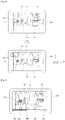
- FIG. 7 is a diagram illustrating a method for setting a reference direction R of a digital device 100 to navigate virtual information 20 surrounded by a zone corresponding to image data 10 in accordance with one embodiment of the present invention.
- the digital device 100 may set its direction at the time when the image data 10 are paged, to the reference direction R.
- examples of contents include photos, moving pictures, and still images.
- various types of contents including at least one image data 10 are provided.
- various methods for paging image data 10 included in the contents on a digital device 100 may exist. For example, if the contents are photos, the image data 10 may be paged by an input of a user who selects a photo of the corresponding image data 10 from a plurality of photos. Also, if the contents are moving pictures, the image data may be paged by an input of a user who pauses the moving pictures from a frame of the corresponding image data 10 while playing the moving pictures.
- the digital device 100 may page the image data 10 by receiving a user input that pauses the moving pictures, and may switch a current mode to a navigating mode of the virtual information 20 corresponding to the corresponding image data 10.
- the digital device 100 may display the image data 10 on the display unit 120 as shown in FIG. 7(b) .
- the digital device 100 switches the current mode to a navigating mode that may detect the virtual information 20 surrounded by the point where the image data 10 are recorded.
- the digital device 100 may set its direction when the user input pausing the moving pictures is received to the reference direction R. Afterwards, the digital device 100 may detect at least one of the panning angle information and the tilting angle information with respect to the set reference direction R, and may display the virtual information 20 surrounded by the zone corresponding to the image data 10.
- FIG. 8 is a diagram illustrating a method for setting a reference direction R of a digital device 100 to navigate virtual information 20 surrounded by a zone corresponding to image data 10 in accordance with a comparative example.
- the digital device 100 may receive the user input for switching to the navigating mode of the virtual information 20.
- the digital device 100 may provide a navigating mode switching interface 30 as shown in FIG. 8(a) , and may receive the user input for the navigating mode switching interface 30.
- the digital device 100 may receive the user input for the navigating mode switching interface 30, and as a result, may switch the current mode to the navigating mode as shown in FIG. 8(b) .
- the digital device 100 may set its direction when the user input is received to the reference direction R. Afterwards, the digital device 100 may detect at least one of the panning angle information and the tilting angle information with respect to the set reference direction R, and may display the virtual information 20 corresponding to the detected information in the target direction.
- FIG. 9 is a diagram illustrating a method for providing contents in accordance with a comparative example.
- the digital device 100 may provide indicators 40a, 40b and 40c, which display an image frame having virtual information 20.
- the moving pictures may include a plurality of image frames.
- Each image frame of the moving pictures may be the image data 10 of the present invention.
- the digital device 100 may display the indicators 40a, 40b and 40c displaying the frame of the image data 10 having the virtual information 20 on a timeline of the moving pictures.
- Each of the indicators 40a, 40b and 40c indicates that the image data 10 of the image frame corresponding to the corresponding indicator includes at least one type of virtual information 20.
- the digital device 100 may display the indicator 40b indicating the image frame having the updated virtual information on the timeline of the moving pictures.
- the image data 10 includes the virtual information 20c updated after the corresponding image data 10 is recorded.
- the digital device 100 may display the indicator 40b corresponding to the image data 10 on the timeline.
- the digital device 100 may provide only the indicator 40b of the image frame having the updated virtual information on the timeline.
- the digital device 100 may display the indicator 40b together with the indicators 40a and 40c of other image frames and control display attributes of the indicator 40b differently from those of the indicators 40a and 40c.
- the digital device may control display attributes of the corresponding indicator.
- the digital device 100 may display the indicator corresponding to the frame of the image data having virtual information more than previously set information, on the timeline.
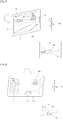
- FIG. 10 is a block diagram illustrating a digital device 100 according to the embodiment of the present invention.
- the digital device 100 of the present invention may include a hardware layer, an operating system layer, and an application layer.
- the hardware layer of the digital device 100 may include a processor 110, a display unit 120, a sensor unit 130, a communication unit 140, and a storage unit 150.
- the display unit 120 outputs image data on a display screen.
- the display unit 120 may output images on the basis of a control command of the processor 110 or contents executed by the processor 110.
- the display unit 120 may display image data included in the contents executed by the digital device 100 and virtual information corresponding to the image data.
- the sensor unit 130 may detect a surrounding environment of the digital device 100 by using at least one sensor provided in the digital device 100 and transfer the detected result to the processor 110. Also, the sensor unit 130 may detect the user input of the present invention and transfer the detected user input to the processor 110. At this time, the sensor unit 130 may include at least one sensing means.
- the at least one sensing means may include a gravity sensor, a terrestrial magnetism sensor, a motion sensor, a gyroscope sensor, an acceleration sensor, an infrared sensor, an inclination sensor, a brightness sensor, an altitude sensor, an odor sensor, a temperature sensor, a depth sensor, a pressure sensor, a bending sensor, an audio sensor, a video sensor, a global positioning system (GPS) sensor, and a touch sensor.
- the sensor unit 130 means various sensing means as described above, may sense various inputs of the user and user environment and transfer the sensed result to the processor 110 to allow the processor 110 to perform an operation based on the sensed result.
- the aforementioned sensors may be included in the digital device 100 as separate elements, or may be included in the digital device 100 by being incorporated into at least one or more elements.
- the communication unit 140 may transmit and receive data to and from an external device or server 1 by performing communication with the external device or server 1 using various protocols.
- the communication unit 140 may transmit and receive digital data, for example, contents to and from the server 1 or cloud by accessing the server 1 or cloud through a network 3.
- the communication unit 140 may receive virtual information corresponding to position information of the image data from the server 1.
- the storage unit 150 of the present invention may store various digital data such as videos, audios, photos, files, and applications.
- the storage unit 150 means various digital data storage space such as a flash memory, a random access memory (RAM), and a solid state drive (SSD).
- the storage unit 150 may store various kinds of contents including image data.
- the storage unit 150 may store contents received by the communication unit 140 from the external device or server.
- the processor 110 of the present invention may execute the contents stored in the storage unit 150 or the contents received through data communication. Also, the processor 110 may execute various applications and process data inside the digital device 100. In the embodiment of the present invention, the processor 110 may drive a content provision module 200 and display the contents of the digital device 100 on the display unit 120 on the basis of a control command of the contents provision module 200. In addition, the processor 110 may control the respective units of the digital device 100 and control data transmission and reception between the units.
- the operating system layer of the digital device 100 may include an operating system that controls the respective units of the digital device 100.
- the operating system may allow the application of the digital device 100 to control and use the respective units of the hardware layer.
- the operating system prepares an environment, which may perform each application, by efficiently distributing resources of the digital device 100.
- the application layer of the digital device 100 may include at least one application.
- the application includes various types of programs to perform a specific task.
- the application may use resources of the hardware layer through assistance from the operating system.
- the digital device 100 includes a contents provision module 180 for providing contents including at least one image data.
- the contents provision module 180 may display image data included in the contents of the digital device 100 together with virtual information corresponding to the image data in accordance with the embodiment of the present invention.
- the contents provision module 180 provides virtual information surrounded by the image data in response to direction change of the digital device 100.
- the virtual information is associated with a zone corresponding to the image data.
- the contents provision module 180 provides direction information of the image data and virtual information in the target direction based on direction change information of the digital device 100.
- the contents provision module 180 may be included in the operating system layer or application layer of the digital device 100.
- the contents provision module 180 may be embedded software built in the operating system layer of the digital device 100, or may be software included in the application layer.
- the digital device 100 shown in FIG. 10 may be a current digital device that sets the reference direction R and detects direction change information in the embodiment of the present invention. Also, the digital device 100 is shown in FIG. 10 in such a manner that respective blocks are shown to logically classify elements of the digital device. Accordingly, the elements of the digital device may be provided as one chip or a plurality of chips depending on design of the device.
- FIG. 11 is a flow chart illustrating a method for providing contents in accordance with the embodiment of the present invention.
- Each step of FIG. 11 may be performed by the digital device of the present invention.
- the processor 110 of the digital device 100 may control the respective steps of FIG. 11 on the basis of a control command of the contents provision module 180 of the digital device 100 shown in FIG. 10 .
- the digital device of the present invention acquires contents including at least one image data (S1110).
- examples of the contents include photos, moving pictures, and still images, and also include various types of contents including at least one image data.
- the digital device may be the same device as the recording device 200 of FIG. 1 . Accordingly, the digital device may acquire contents through the recording procedure described in FIG. 1 . Also, according to another embodiment of the present invention, the digital device may receive the contents from the external device or server.
- the digital device acquires additional data of the contents (S1120).
- the additional data include position information and direction information of the recording device when the image data included in the contents are recorded.
- the position information of the recording device is the position information on the GPS, and the direction information of the recording device includes at least one of panning angle information and tilting angle information.
- the embodiment of the position information and the direction information of the recording device will be described with reference to FIG. 1 . If the digital device is the same device as the recording device 200 of FIG. 1 , it may acquire the position information and the direction information through the detecting procedure described in FIG. 1 . Also, according to another embodiment of the present invention, the digital device may receive the position information and the direction information from the external device or server.
- the digital device acquires virtual information corresponding to position information of the image data (S1130).
- the virtual information includes augmented reality information on at least one object surrounded by a point corresponding to the position information.
- the acquired virtual information may include augmented reality information of surrounding objects located within a predetermined distance based on the point corresponding to the corresponding position information.
- the surrounding objects may include objects located at every side based on the point.
- the virtual information includes various kinds of augmented reality information.
- the virtual information may include information (for example, name, type of business and business hours of a corresponding store) on a specific building or store, and may include message information from the user or a follower of the user with respect to a specific building.
- the virtual information may include current weather information of the corresponding point.
- the digital device may receive the virtual information from the server.
- the virtual information may be collected together with the image data when the recording device records the image data. At this time, the digital device may acquire the virtual information collected by the recording device together with the image data.
- the digital device displays the image data included in the contents (S1140). At this time, the digital device may display the virtual information corresponding to the image data, together with the image data, as described in more detail in FIG. 2 .
- the digital device sets a reference direction of a current digital device that displays the image data (S1150).
- the current digital device means the digital device 100 that displays the image data 10 in FIG. 2 to FIG. 10 .
- the reference direction is the direction of the current digital device at a specific timing point.
- the direction of the current digital device may be set in various manners as described with reference to FIG. 2 .
- the reference direction may be set at various timing points.
- the digital device may set the direction of the current digital device to the reference direction at the time when the image data are paged.
- the digital device may set the direction of the current digital device to the reference direction at the time when a separate user input for navigating the virtual information is received.
- the virtual information is associated with a zone corresponding to the image data.
- the digital device detects direction change information of the current digital device with respect to the reference direction (S1160).
- the direction change information includes at least one of the panning angle information and the tilting angle information of the current digital device.
- the digital device may include at least one of a compass sensor and a gyroscope sensor, and may detect at least one of its panning angle and tilting angle in real time by using the sensor.
- the digital device displays the direction information of the image data and virtual information in the target direction based on the detected direction change information of the current digital device (S1170).
- the digital device acquires the target direction by compensating for at least one of the panning angle information and the tilting angle information with respect to the direction information of the image data.
- the digital device displays the virtual information of a zone located in the target direction, from the received virtual information, through the display unit, as described in more detail with reference to FIG. 3 to FIG. 6 .
- the digital device includes a display unit such as a cellular phone, a PDA, a tablet computer, a digital camera, a camcorder, and other portable devices, and includes various kinds of devices that may output contents through the display unit.
- a display unit such as a cellular phone, a PDA, a tablet computer, a digital camera, a camcorder, and other portable devices, and includes various kinds of devices that may output contents through the display unit.
Landscapes
- Engineering & Computer Science (AREA)
- Theoretical Computer Science (AREA)
- Physics & Mathematics (AREA)
- General Physics & Mathematics (AREA)
- Computer Hardware Design (AREA)
- Human Computer Interaction (AREA)
- General Engineering & Computer Science (AREA)
- Computer Graphics (AREA)
- Multimedia (AREA)
- Signal Processing (AREA)
- User Interface Of Digital Computer (AREA)
- Processing Or Creating Images (AREA)
Description
- The present invention relates to a method for providing contents and a digital device for the same, and more particularly, to a method for providing contents and a digital device for the same, in which image data included in contents are displayed and navigated together with augmented reality information surrounded by a point where the corresponding image data are recorded.
- Augmented reality is the technology that displays image or background of reality together with virtual information. Unlike the virtual reality technology in which object, background and environment are provided as virtual images, the augmented reality technology provides a user with realer additional information than the actual environment by mixing a virtual object with an actual environment. For example, if the user illuminates surroundings of the road through a camera of a digital device while walking the road, information on buildings and road information included in images collected in the camera may be provided to the user. This augmented reality technology has received much more attention as a portable device has been recently spread.
-
US 2009/0278948 A1 discloses a method of presenting information, capable of displaying an image including one or more objects being in the vicinity of the ground. The method includes the steps of: acquiring viewpoint information; acquiring visual line information; acquiring posture information; acquiring additional information related to the object position information; calculating horizon line information in the image; determining a reference line on the image on the basis of the horizon line information and the posture information; calculating distance information from the viewpoint position to the object; determining a display attribute of the additional information including a display mode of the additional information and a display position of the additional information in the image with respect to the reference line; and presenting the additional information on the basis of the display mode so as to reveal a relationship between the additional information and the object when displaying the image on the display unit. -
US 2011/0193985 A1 discloses an imaging device having an imaging portion that images a subject; a positional information acquisition portion that acquires positional information of an imaging position; a control portion which acquires information on the subject based on the positional information, and displays image data of the subject and the information on the subject on a display portion; and a hold control portion that outputs a hold control signal, which holds the image data of the subject and the information on the subject, to the control portion. - Accordingly, the present invention is directed to a method for providing contents and a digital device for the same, which substantially obviate one or more problems due to limitations and disadvantages of the related art.
- An object of the present invention is to provide a method for providing contents and a digital device for the same in which image data are displayed through a digital device together with augmented reality information of an object included in the corresponding image data.
- Another object of the present invention is to provide a method for providing contents and a digital device for the same in which image data are navigated through a digital device together with augmented reality information surrounded by a point where the image data are recorded.
- Additional advantages, objects, and features of the invention will be set forth in part in the description which follows and in part will become apparent to those having ordinary skill in the art upon examination of the following or may be learned from practice of the invention. The objectives and other advantages of the invention may be realized and attained by the structure particularly pointed out in the written description and claims hereof as well as the appended drawings.
- The above identified objects are solved by the features of the independent claims.
- According to the method for providing contents in accordance with the embodiment of the present invention, the digital device may display image data together with augmented reality information associated with the image data. As a result, information on objects included in the image data may easily be provided to the user.
- Also, according to the embodiment of the present invention, augmented reality information surrounded by a point where image data are recorded is provided on the basis of direction change of the current digital device that displays the image data. Accordingly, the user may navigate the augmented reality information as if he/she is located in the place where the corresponding image data are recorded.
- Also, according to the embodiment of the present invention, augmented reality information in the corresponding point may be received in real time by using position information of a recording device when the image data are recorded. Accordingly, the user may receive the latest augmented reality information surrounded by the corresponding point through the digital device.
- It is to be understood that both the foregoing general description and the following detailed description of the present invention are exemplary and explanatory and are intended to provide further explanation of the invention as claimed.
- The accompanying drawings, which are included to provide a further understanding of the invention and are incorporated in and constitute a part of this application, illustrate embodiment(s) of the invention and together with the description serve to explain the principle of the invention. In the drawings:
-
FIG. 1 is a diagram illustrating that a recording device records image data; -
FIG. 2 is a diagram illustrating a digital device that displays image data in accordance with the embodiment of the present invention; -
FIG. 3 is a diagram illustrating that virtual information is displayed through a digital device in accordance with one embodiment of the present invention; -
FIG. 4 to FIG. 6 are diagrams illustrating that virtual information is displayed through a digital device in accordance with a comparative example; -
FIG. 7 is a diagram illustrating a method for setting a reference direction of a digital device in accordance with one embodiment of the present invention; -
FIG. 8 is a diagram illustrating a method for setting a reference direction of a digital device in accordance with a comparative example; -
FIG. 9 is a diagram illustrating a method for providing an indicator indicating an image frame having virtual information in accordance with a comparative example; -
FIG. 10 is a block diagram illustrating a digital device according to the embodiment of the present invention; and -
FIG. 11 is a flow chart illustrating a method for providing contents in accordance with the embodiment of the present invention. - Reference will now be made in detail to the preferred embodiments of the present invention, examples of which are illustrated in the accompanying drawings. Wherever possible, the same reference numbers will be used throughout the drawings to refer to the same or like parts.
- Although the terms used in the present invention are selected from generally known and used terms considering their functions in the present invention, the terms can be modified depending on intention of a person skilled in the art, practices, or the advent of new technology. Also, in special case, the terms mentioned in the description of the present invention may be selected by the applicant at his or her discretion, the detailed meanings of which are described in relevant parts of the description herein. Accordingly, the terms used herein should be understood not simply by the actual terms used but by the meaning lying within and the description disclosed herein.
- The present invention is intended to display image data through a digital device together with virtual information of objects included in the corresponding image data. Also, the present invention is to provide a method for navigating virtual information of image data displayed through a digital device and virtual information of a zone surrounded by a point where the corresponding image data are recorded. In the present invention, the virtual information includes augmented reality information on a specific object.
-
FIG. 1 is a diagram illustrating that arecording device 200records image data 10. - Referring to
FIG. 1 , therecording device 200 may record contents, which includeimage data 10, by using a camera unit (not shown). At this time, examples of the contents recorded by therecording device 200 may include photos, moving pictures, and still images. Also, various types of contents including at least oneimage data 10 may be recorded by therecording device 200. A user may record images of various types of objects such as a specific building and specific road by using therecording device 200. Theimage data 10 are generated through the recorded images. - In the meantime,
virtual information image data 10 may exist in the at least one object. Thevirtual information image data 10. For example, thevirtual information image data 10. If therecording device 200 provides an augmented reality function, thevirtual information display unit 220 of therecording device 200 together with theimage data 10. Therecording device 200 may record thevirtual information image data 10 when recording theimage data 10. - The
recording device 200 detects position information P of thecorresponding recording device 200 when recording theimage data 10. The position information P of therecording device 200 may be the position information of the point where therecording device 200 is located on a global positioning system (GPS). Therecording device 200 may detect the position information P by using a GPS receiving device. Therecording device 200 may indirectly detect its position information P through a network connected therewith. - In addition, the
recording device 200 detects direction information (θ, 0) together with theimage data 10 when recording theimage data 10. The direction information (θ, 0) of therecording device 200 includes at least one of panning angle information and tilting angle information of therecording device 200. At this time, the panning angle information and the tilting angle information represent an angle between the direction of therecording device 200 and a first reference direction. The direction of therecording device 200 may be set in various manners. For example, a recording direction of the camera unit of therecording device 200 may be set to the direction of therecording device 200. Also, the first reference direction may be set to a specific orientation (for example, northern direction), altitude (for example,altitude 0°), or their combination. Accordingly, therecording device 200 may detect its panned angle on the basis of a specific orientation, that is, northern (N) direction. Also, the recording device may detect its tilting angle on the basis of a specific altitude, that is,altitude 0°. InFIG. 1 , therecording device 200 has a panning angle of θ and a tilting angle of 0° with reference to the first reference direction. Accordingly, inFIG. 1 , the direction information of therecording device 200 becomes (θ, 0). - The
recording device 200 may include at least one of a compass sensor and a gyroscope sensor, and may detect at least one of its panning angle information and tilting angle information by using a sensor provided therein. However, the first reference direction and the direction of therecording device 200 are only exemplary to describe a method for obtaining the direction information (θ, 0), and various modifications may be made in the first reference direction and the direction of therecording device 200. - The
recording device 200 stores the position information (P) and the direction information (θ, 0) when recording theimage data 10. The contents, which include at least oneimage data 10, may have at least one position information (P) and direction information (θ, 0) corresponding to eachimage data 10. The at least one position information (P) and direction information (θ, 0) may be stored together as additional data of the corresponding contents. - In the meantime, the direction information of the
image data 10 may further include altitude information of therecording device 200 as well as panning angle information and tilting angle information of therecording device 200. Even though therecording device 200 has the same panning angle and tilting angle at the same point P, if therecording device 200 is located on different altitudes,different image data 10 may be recorded in thecorresponding recording device 200. Accordingly, therecording device 200 may detect its altitude information when recording theimage data 10, and may allow the detected altitude information to be included in the direction information of theimage data 10. To this end, therecording device 200 may include various kinds of sensors for detecting altitude information. -
FIG. 2 is a diagram illustrating adigital device 100 that displaysimage data 10 in accordance with the embodiment of the present invention. - In the embodiment of the present invention, the
digital device 100 may include adisplay unit 120, and may display theimage data 10 through thedisplay unit 120. Thedigital device 100 may acquire contents, which include at least oneimage data 10. According to one embodiment of the present invention, thedigital device 100 may be the same device as therecording device 200 ofFIG. 1 . Accordingly, thedigital device 100 may acquire contents through the recording procedure described inFIG. 1 . Also, according to another embodiment of the present invention, thedigital device 100 may receive the contents from an external device or server. - The
digital device 100 acquires additional data of the contents together with the contents. The additional data may include position information (P) and direction information (θ, 0) when recording theimage data 10 included in the contents. If thedigital device 100 is the same device as therecording device 200 ofFIG. 1 , it may acquire the position information (P) and direction information (θ, 0) through the detecting procedure described inFIG. 1 . Also, according to another embodiment of the present invention, thedigital device 100 may receive the position information (P) and direction information (θ, 0) from the external device or server. - The
digital device 100 of the present invention may display theimage data 10 included in the contents. At this time, thedigital device 100 may display the image data together withvirtual information image data 10. To this end, thedigital device 100 may receive thevirtual information image data 10. In other words, thedigital device 100 transmits the position information (P) of theimage data 10 to the server, and receives the virtual information corresponding to the corresponding position information (P) from the server. At this time, the received virtual information may include augmented reality information on at least one object surrounded by the point corresponding to the corresponding position information (P). For example, the received virtual information may include augmented reality information on surrounding objects located within a certain distance based on the point corresponding to the corresponding position information (P). The surrounding objects may include objects located on every side based on the point. - If the virtual information is received, the
digital device 100 may determine virtual information which will be displayed on the display unit, by using the direction information (θ, 0) of theimage data 10. In other words, thedigital device 100 may display the virtual information located in the direction (θ, 0) based on the point P, among the virtual information corresponding to the position information (P), through thedisplay unit 120. Accordingly, thedigital device 100 may display theimage data 10 on thedisplay unit 120 together with thevirtual information image data 10. In the meantime, according to the embodiment of the present invention, thedigital device 100 may receive the virtual information from the server by using the position information (P) of theimage data 10. Accordingly, thedigital device 100 may display thevirtual information 20c, which is updated after recording, as well as thevirtual information image data 10. - According to another embodiment of the present invention, the
recording device 200 ofFIG. 1 may record theimage data 10 together with thevirtual information digital device 100 ofFIG. 2 may display the recordedvirtual information image data 10. - In the meantime, according to the embodiment of the present invention, the user may navigate surrounding information of the
image data 10 by using thedigital device 100. In other words, the user may navigate augmented reality information surrounded by the point P where theimage data 10 are recorded, by using thedigital device 100. To this end, thedigital device 100 sets a reference direction R of thedigital device 100 at a specific timing point. The reference direction is the direction of thedigital device 100 at the specific timing point. In the embodiment of the present invention, the direction of thedigital device 100 may be set in various manners. For example, the direction of thedigital device 100 may be an opposite direction of a display direction of theimage data 10 displayed by thedisplay unit 120 of thedigital device 100. In other words, according to the embodiment of the present invention, the user may set a viewing direction of thedisplay unit 120 of thedigital device 100 to the direction of thedigital device 100. However, the method for setting the reference direction R of thedigital device 100 is one embodiment of the present invention, and various modifications may be made in the method. - In the embodiment of the present invention, the timing point when the reference direction R is set may be set in various manners. For example, the
digital device 100 may set its direction to the reference direction R at the time when theimage data 10 are paged. Alternatively, thedigital device 100 may set its direction to the reference direction R at the time when a separate user input for navigating surrounding information of theimage data 10 is received. - In this way, if the reference direction R of the
digital device 100 is set, the reference direction R may be synchronized with the direction information (θ, 0) of theimage data 10. In other words, thedigital device 100 oriented towards the reference direction R becomes the state that it is oriented towards the direction (θ, 0) at the recording point P of theimage data 10. Accordingly, if thedigital device 100 is oriented towards the reference direction R, it displays thevirtual objects display unit 120. - Next, the
digital device 100 detects its direction change information on the reference direction R. The direction change information includes at least one of panning angle information and tilting angle information of thedigital device 100 with respect to the reference direction R. In other words, thedigital device 100 detects at least one of the panning angle and the tilting angle between the direction of thedigital device 100 and the reference direction R in real-time by using the reference direction R as the second reference direction of the present invention. In the embodiment of the present invention, thedigital device 100 may include at least one of a compass sensor and a gyroscope sensor, and may detect at least one of the panning angle information and the tilting angle information by using the sensor. - The
digital device 100 displays virtual information in a target direction based on the detected direction change information and the direction information (θ, 0) of theimage data 10. In more detail, thedigital device 100 acquires the target direction by compensating for at least one of the detected panning angle information and tilting angle information with respect to the direction information (θ, 0) of theimage data 10. Thedigital device 100 displays the virtual information located in the target direction, from the received virtual information, on thedisplay unit 120. In other words, thedigital device 100 may display the virtual information located in the target direction, from the surrounding virtual information based on the point P. Accordingly, according to the embodiment of the present invention, when the direction of thedigital device 100 is changed from the reference direction R, it may be advantageous in that the direction change of thedigital device 100 is made in the direction (θ, 0) of the point P. The displaying virtual information in accordance with direction change information of thedigital device 100 will be described in more detail with reference toFIG. 3 to FIG. 6 . -
FIG. 3 is a diagram illustrating that virtual information is displayed through adigital device 100 in accordance with one embodiment of the present invention. - As described in
FIG. 2 , if the reference direction R of thedigital device 100 is set, thedigital device 100 detects its direction change information with respect to the reference direction R. In the embodiment ofFIG. 3 , the user may tilt thedigital device 100 towards the right side. At this time, thedigital device 100 is subjected to panning at an angle of 'α' clockwise with respect to the reference direction R. - The
digital device 100 acquires a target direction of (θ+α, 0) by compensating for the detected direction change information 'α' with respect to panning angle information θ of the direction information (θ, 0) of theimage data 10. At this time, thevirtual information image data 10 are recorded. Thedigital device 100 displays thevirtual information display unit 120. Accordingly, thedigital device 100 of the present invention may provide the user with the virtual information the same as that actually viewed in the direction (θ+α, 0) at the point P. - In the meantime, when the
digital device 100 is subjected to panning towards the right side inFIG. 3 , it may display theimage data 10 displayed on thedisplay unit 120 by shifting theimage data 10 to its left side. At this time, thedigital device 100 may shift theimage data 10 on thedisplay unit 120 in accordance with its panning angle. Accordingly, thedigital device 100 may display theimage data 10 to be fixed in the reference direction R. - Although the method for displaying virtual information when panning of the
digital device 100 is made has been described in the embodiment ofFIG. 3 , the present invention is not limited to the embodiment ofFIG. 3 . In other words, when thedigital device 100 is tilted, the virtual information may be displayed in the same manner even though tilting and panning of thedigital device 100 are made at the same time. -
FIG. 4 to FIG. 6 are diagrams illustrating that virtual information is displayed through adigital device 100 in accordance with a comparative example. - According to the comparative example of
FIG. 4 to FIG. 6 , thedigital device 100 may receive surrounding view data corresponding to the position information P of the image data, and may display the surrounding view data on thedisplay unit 120 on the basis of its target direction. The surrounding view data include image data on surroundings viewed from a point corresponding to the position information P. Thedigital device 100 of the present invention may receive surrounding view data corresponding to the position information P from the server. - First of all, as shown in
FIG. 4 , if the user tilts thedigital device 100 towards the right side, thedigital device 100 is subjected to panning at an angle of α clockwise with respect to the reference direction R. Thedigital device 100 detects its direction change information α. Then, thedigital device 100 acquires a target direction of (θ+α, 0) by compensating for the detected direction change information 'α' with respect to panning angle information θ of the direction information (θ, 0) of theimage data 10. At this time, thevirtual information image data 10 are recorded. Thedigital device 100 displays thevirtual information display unit 120. - In the meantime, according to the comparative example of
FIG. 4 , thedigital device 100 may displayview data 14 of the zone located in the target direction (θ+α, 0), from the received surrounding view data, through thedisplay unit 120. In other words, thedigital device 100 may display theview data 14 of the target direction (θ+α, 0) and thevirtual information display unit 120. Accordingly, thedigital device 100 of the present invention may provide the user with view image the same as that actually viewed in the direction (θ+α, 0) at the point P and the virtual information corresponding to the view image. - Likewise, as shown in
FIG. 5 , if the user tilts thedigital device 100 towards the left side, thedigital device 100 is subjected to panning at an angle of β counterclockwise with respect to the reference direction R. Thedigital device 100 detects its direction change information β. Then, thedigital device 100 acquires a target direction of (θ-β, 0) by compensating for the detected direction change information 'β' with respect to panning angle information θ of the direction information (θ, 0) of theimage data 10. At this time, thevirtual information image data 10 are recorded. Thedigital device 100 displays thevirtual information display unit 120. Also, thedigital device 100 may displayview data 14 of the zone located in the target direction (θ-β, 0), from the received surrounding view data, on thedisplay unit 120 together with thevirtual information - In the meantime, in the embodiment of
FIG. 4 andFIG. 5 , clockwise panning of thedigital device 100 has been described as positive compensation of panning angle information, and counterclockwise panning of thedigital device 100 has been described as negative compensation of panning angle information. However, this is not limited to the comparative example ofFIG. 4 andFIG. 5 . In other words, clockwise panning of thedigital device 100 has been described as negative compensation of panning angle information, and counterclockwise panning of thedigital device 100 has been described as positive compensation of panning angle information. - Next, referring to
FIG. 6 , thedigital device 100 may detect its tilting angle information as well as its panning angle information. As shown inFIG. 6 , if the user tilts thedigital device 100 upwardly, thedigital device 100 is titled upwardly at an angle of γ with respect to the reference direction R. Thedigital device 100 detects its direction change information γ. Then, thedigital device 100 acquires a target direction of (θ, γ) by compensating for the detected direction change information 'γ' with respect to tiltingangle information 0° of the direction information (θ, 0) of theimage data 10. At this time,virtual information 20g may exist in a zone located in the target direction (θ, γ) at the point P where theimage data 10 are recorded. Thedigital device 100 displays thevirtual information 20g located in the target direction (θ, γ) on thedisplay unit 120. Also, thedigital device 100 may displayview data 14 of the zone located in the target direction (θ, γ), from the received surrounding view data, on thedisplay unit 120 together with thevirtual information 20g. - In the meantime, in
FIG. 3 to FIG. 6 , it has been assumed that the panning angle information in the direction information of the image data is θ and the tilting angle information is 0. However, various angles may be applied to the direction information of theimage data 10. According to the embodiment of the present invention, the direction information of theimage data 10 may include any one of the panning angle information and the tilting angle information of the recording device, or may include both of them Also, according to another embodiment of the present invention, the direction information of theimage data 10 may further include altitude information of the recording device. - Also, in the embodiment of the present invention, the virtual information 20 includes various kinds of augmented reality information. In other words, the virtual information may include information (for example, name, type of business and business hours of a corresponding store) on a specific building or store, and its examples are 20a, 20b, 20d and 20e. Also, the virtual information may include message information from the user or a follower of the user with respect to a specific building, and its examples are 20c and 20f. Moreover, the virtual information may include current weather information of the corresponding point P and its example is 20g.
- As described above, according to the embodiment of the present invention, the user may navigate the virtual information 20 surrounded by the
image data 10 through thedigital device 100. Also, the user may navigateview data 14 surrounded by theimage data 10 together with the virtual information through thedigital device 10. Thedigital device 100 of the present invention provides reality as if the user is located at the point P to look around the surrounding through thedigital device 100. -
FIG. 7 is a diagram illustrating a method for setting a reference direction R of adigital device 100 to navigate virtual information 20 surrounded by a zone corresponding to imagedata 10 in accordance with one embodiment of the present invention. - According to one embodiment of the present invention, the
digital device 100 may set its direction at the time when theimage data 10 are paged, to the reference direction R. In the embodiment of the present invention, examples of contents include photos, moving pictures, and still images. Also, various types of contents including at least oneimage data 10 are provided. In the present invention, various methods forpaging image data 10 included in the contents on adigital device 100 may exist. For example, if the contents are photos, theimage data 10 may be paged by an input of a user who selects a photo of thecorresponding image data 10 from a plurality of photos. Also, if the contents are moving pictures, the image data may be paged by an input of a user who pauses the moving pictures from a frame of thecorresponding image data 10 while playing the moving pictures. - As shown in
FIG. 7 , if the contents of the present invention are moving pictures, thedigital device 100 may page theimage data 10 by receiving a user input that pauses the moving pictures, and may switch a current mode to a navigating mode of the virtual information 20 corresponding to thecorresponding image data 10. In other words, as shown inFIG. 7(a) , if the user input that pauses moving pictures is received while the corresponding moving pictures are being played, thedigital device 100 may display theimage data 10 on thedisplay unit 120 as shown inFIG. 7(b) . Also, in a state that thedigital device 100 displays theimage data 10 on thedisplay unit 120, thedigital device 100 switches the current mode to a navigating mode that may detect the virtual information 20 surrounded by the point where theimage data 10 are recorded. At this time, thedigital device 100 may set its direction when the user input pausing the moving pictures is received to the reference direction R. Afterwards, thedigital device 100 may detect at least one of the panning angle information and the tilting angle information with respect to the set reference direction R, and may display the virtual information 20 surrounded by the zone corresponding to theimage data 10. -
FIG. 8 is a diagram illustrating a method for setting a reference direction R of adigital device 100 to navigate virtual information 20 surrounded by a zone corresponding to imagedata 10 in accordance with a comparative example. - According to the comparative example of
FIG. 8 , thedigital device 100 may receive the user input for switching to the navigating mode of the virtual information 20. For example, thedigital device 100 may provide a navigatingmode switching interface 30 as shown inFIG. 8(a) , and may receive the user input for the navigatingmode switching interface 30. In a state that thedigital device 100 displays the image data on thedisplay unit 120, thedigital device 100 may receive the user input for the navigatingmode switching interface 30, and as a result, may switch the current mode to the navigating mode as shown inFIG. 8(b) . Thedigital device 100 may set its direction when the user input is received to the reference direction R. Afterwards, thedigital device 100 may detect at least one of the panning angle information and the tilting angle information with respect to the set reference direction R, and may display the virtual information 20 corresponding to the detected information in the target direction. -
FIG. 9 is a diagram illustrating a method for providing contents in accordance with a comparative example. Referring toFIG. 9 , thedigital device 100 may provideindicators - If the contents provided on the
digital device 100 are moving pictures, the moving pictures may include a plurality of image frames. Each image frame of the moving pictures may be theimage data 10 of the present invention. Thedigital device 100 may display theindicators image data 10 having the virtual information 20 on a timeline of the moving pictures. Each of theindicators image data 10 of the image frame corresponding to the corresponding indicator includes at least one type of virtual information 20. - Also, if there is virtual information updated after the
image data 10 are recorded, thedigital device 100 may display theindicator 40b indicating the image frame having the updated virtual information on the timeline of the moving pictures. In the comparative example ofFIG. 9 , theimage data 10 includes thevirtual information 20c updated after thecorresponding image data 10 is recorded. Accordingly, thedigital device 100 may display theindicator 40b corresponding to theimage data 10 on the timeline. Thedigital device 100 may provide only theindicator 40b of the image frame having the updated virtual information on the timeline. Alternatively, thedigital device 100 may display theindicator 40b together with theindicators indicator 40b differently from those of theindicators - In the meantime, if the moving pictures have
many image data 10 having the virtual information, the digital device may control display attributes of the corresponding indicator. For example, thedigital device 100 may display the indicator corresponding to the frame of the image data having virtual information more than previously set information, on the timeline. -
FIG. 10 is a block diagram illustrating adigital device 100 according to the embodiment of the present invention. - Referring to
FIG. 10 , thedigital device 100 of the present invention may include a hardware layer, an operating system layer, and an application layer. - First of all, the hardware layer of the
digital device 100 may include aprocessor 110, adisplay unit 120, asensor unit 130, acommunication unit 140, and astorage unit 150. - The
display unit 120 outputs image data on a display screen. Thedisplay unit 120 may output images on the basis of a control command of theprocessor 110 or contents executed by theprocessor 110. In the embodiment of the present invention, thedisplay unit 120 may display image data included in the contents executed by thedigital device 100 and virtual information corresponding to the image data. - The
sensor unit 130 may detect a surrounding environment of thedigital device 100 by using at least one sensor provided in thedigital device 100 and transfer the detected result to theprocessor 110. Also, thesensor unit 130 may detect the user input of the present invention and transfer the detected user input to theprocessor 110. At this time, thesensor unit 130 may include at least one sensing means. Examples of the at least one sensing means may include a gravity sensor, a terrestrial magnetism sensor, a motion sensor, a gyroscope sensor, an acceleration sensor, an infrared sensor, an inclination sensor, a brightness sensor, an altitude sensor, an odor sensor, a temperature sensor, a depth sensor, a pressure sensor, a bending sensor, an audio sensor, a video sensor, a global positioning system (GPS) sensor, and a touch sensor. Thesensor unit 130 means various sensing means as described above, may sense various inputs of the user and user environment and transfer the sensed result to theprocessor 110 to allow theprocessor 110 to perform an operation based on the sensed result. The aforementioned sensors may be included in thedigital device 100 as separate elements, or may be included in thedigital device 100 by being incorporated into at least one or more elements. - Next, the
communication unit 140 may transmit and receive data to and from an external device or server 1 by performing communication with the external device or server 1 using various protocols. In the present invention, thecommunication unit 140 may transmit and receive digital data, for example, contents to and from the server 1 or cloud by accessing the server 1 or cloud through anetwork 3. Also, in the embodiment of the present invention, thecommunication unit 140 may receive virtual information corresponding to position information of the image data from the server 1. - Next, the
storage unit 150 of the present invention may store various digital data such as videos, audios, photos, files, and applications. Thestorage unit 150 means various digital data storage space such as a flash memory, a random access memory (RAM), and a solid state drive (SSD). In the embodiment of the present invention, thestorage unit 150 may store various kinds of contents including image data. Also, thestorage unit 150 may store contents received by thecommunication unit 140 from the external device or server. - The
processor 110 of the present invention may execute the contents stored in thestorage unit 150 or the contents received through data communication. Also, theprocessor 110 may execute various applications and process data inside thedigital device 100. In the embodiment of the present invention, theprocessor 110 may drive acontent provision module 200 and display the contents of thedigital device 100 on thedisplay unit 120 on the basis of a control command of thecontents provision module 200. In addition, theprocessor 110 may control the respective units of thedigital device 100 and control data transmission and reception between the units. - Next, the operating system layer of the
digital device 100 may include an operating system that controls the respective units of thedigital device 100. The operating system may allow the application of thedigital device 100 to control and use the respective units of the hardware layer. The operating system prepares an environment, which may perform each application, by efficiently distributing resources of thedigital device 100. In the meantime, the application layer of thedigital device 100 may include at least one application. The application includes various types of programs to perform a specific task. The application may use resources of the hardware layer through assistance from the operating system. - According to the embodiment of the present invention, the
digital device 100 includes acontents provision module 180 for providing contents including at least one image data. Thecontents provision module 180 may display image data included in the contents of thedigital device 100 together with virtual information corresponding to the image data in accordance with the embodiment of the present invention. Also, thecontents provision module 180 provides virtual information surrounded by the image data in response to direction change of thedigital device 100. The virtual information is associated with a zone corresponding to the image data. In other words, thecontents provision module 180 provides direction information of the image data and virtual information in the target direction based on direction change information of thedigital device 100. In the present invention, thecontents provision module 180 may be included in the operating system layer or application layer of thedigital device 100. In other words, thecontents provision module 180 may be embedded software built in the operating system layer of thedigital device 100, or may be software included in the application layer. - The
digital device 100 shown inFIG. 10 may be a current digital device that sets the reference direction R and detects direction change information in the embodiment of the present invention. Also, thedigital device 100 is shown inFIG. 10 in such a manner that respective blocks are shown to logically classify elements of the digital device. Accordingly, the elements of the digital device may be provided as one chip or a plurality of chips depending on design of the device. -
FIG. 11 is a flow chart illustrating a method for providing contents in accordance with the embodiment of the present invention. - Each step of
FIG. 11 , which will be described hereinafter, may be performed by the digital device of the present invention. In other words, theprocessor 110 of thedigital device 100 may control the respective steps ofFIG. 11 on the basis of a control command of thecontents provision module 180 of thedigital device 100 shown inFIG. 10 . - First of all, the digital device of the present invention acquires contents including at least one image data (S1110). In the embodiment of the present invention, examples of the contents include photos, moving pictures, and still images, and also include various types of contents including at least one image data. According to one embodiment of the present invention, the digital device may be the same device as the
recording device 200 ofFIG. 1 . Accordingly, the digital device may acquire contents through the recording procedure described inFIG. 1 . Also, according to another embodiment of the present invention, the digital device may receive the contents from the external device or server. - Next, the digital device acquires additional data of the contents (S1120). The additional data include position information and direction information of the recording device when the image data included in the contents are recorded. The position information of the recording device is the position information on the GPS, and the direction information of the recording device includes at least one of panning angle information and tilting angle information. The embodiment of the position information and the direction information of the recording device will be described with reference to
FIG. 1 . If the digital device is the same device as therecording device 200 ofFIG. 1 , it may acquire the position information and the direction information through the detecting procedure described inFIG. 1 . Also, according to another embodiment of the present invention, the digital device may receive the position information and the direction information from the external device or server. - Next, the digital device acquires virtual information corresponding to position information of the image data (S1130). The virtual information includes augmented reality information on at least one object surrounded by a point corresponding to the position information. For example, the acquired virtual information may include augmented reality information of surrounding objects located within a predetermined distance based on the point corresponding to the corresponding position information. The surrounding objects may include objects located at every side based on the point. According to the embodiment of the present invention, the virtual information includes various kinds of augmented reality information. In other words, the virtual information may include information (for example, name, type of business and business hours of a corresponding store) on a specific building or store, and may include message information from the user or a follower of the user with respect to a specific building. Also, the virtual information may include current weather information of the corresponding point. According to one embodiment of the present invention, the digital device may receive the virtual information from the server. However, according to another embodiment of the present invention, the virtual information may be collected together with the image data when the recording device records the image data. At this time, the digital device may acquire the virtual information collected by the recording device together with the image data.
- Next, the digital device displays the image data included in the contents (S1140). At this time, the digital device may display the virtual information corresponding to the image data, together with the image data, as described in more detail in
FIG. 2 . - Next, the digital device sets a reference direction of a current digital device that displays the image data (S1150). The current digital device means the
digital device 100 that displays theimage data 10 inFIG. 2 to FIG. 10 . The reference direction is the direction of the current digital device at a specific timing point. In the embodiment of the present invention, the direction of the current digital device may be set in various manners as described with reference toFIG. 2 . Also, in the embodiment of the present invention, the reference direction may be set at various timing points. For example, the digital device may set the direction of the current digital device to the reference direction at the time when the image data are paged. In a comparative example, the digital device may set the direction of the current digital device to the reference direction at the time when a separate user input for navigating the virtual information is received. The virtual information is associated with a zone corresponding to the image data. - Next, the digital device detects direction change information of the current digital device with respect to the reference direction (S1160). The direction change information includes at least one of the panning angle information and the tilting angle information of the current digital device. The digital device may include at least one of a compass sensor and a gyroscope sensor, and may detect at least one of its panning angle and tilting angle in real time by using the sensor.
- Next, the digital device displays the direction information of the image data and virtual information in the target direction based on the detected direction change information of the current digital device (S1170). In more detail, the digital device acquires the target direction by compensating for at least one of the panning angle information and the tilting angle information with respect to the direction information of the image data. The digital device displays the virtual information of a zone located in the target direction, from the received virtual information, through the display unit, as described in more detail with reference to
FIG. 3 to FIG. 6 . - In the present invention, the digital device includes a display unit such as a cellular phone, a PDA, a tablet computer, a digital camera, a camcorder, and other portable devices, and includes various kinds of devices that may output contents through the display unit.
- It will be apparent to those skilled in the art that the present invention can be embodied in other specific forms without departing from the spirit and essential characteristics of the invention. Thus, the above embodiments are to be considered in all respects as illustrative and not restrictive. The scope of the invention should be determined by reasonable interpretation of the appended claims and all change which comes within the equivalent scope of the invention are included in the scope of the invention.
- Various embodiments have been described in the best mode for carrying out the disclosure.
Claims (2)
- A digital device (100) comprising:a processor (110) configured to control an operation of the digital device (100);a display unit (120) configured to output an image on the basis of a command of the processor (110); anda sensor unit (130) configured to sense a direction of the digital device (100) and transferring the sensed result to the processor (110),wherein the processor (110) is configured to:acquire (S1110) moving pictures as contents including at least one image data (10),acquire (S1120) additional data of the contents, wherein the additional data are position information ((P)) being a point in a global positioning system, GPS, of a location of a recording device (200) and a recording direction of a camera unit of the recording device (200) for recording the moving pictures, at least one of panning angle information and tilting angle information of the recording device (200) as direction information (Θ, 0) of the recording device (200), the additional data are stored by the recording device (200) when the image data (10) included in the contents are recorded,acquire (S1130) virtual information (20a, 20b, 20c) corresponding to the position information ((P)) of the image data (10), wherein the virtual information (20a, 20b, 20c) include augmented reality information on at least one object located within a certain distance to a point corresponding to the position information ((P)),display (S1140) the image data (10) included in the contents as moving pictures on the display unit (120),page the image data (10) by receiving a user input, detected by the sensor unit (130) that pauses the moving pictures at a frame of the moving pictures;set (S1150) a current direction of the digital device (100) as a reference direction (R) by the paging of the image data (10),detect (S1160) direction change information (α, β, γ) of the digital device (100) with respect to the reference direction (R), the direction change information (α, β, γ) includes at least one of panning angle information and tilting angle information of the digital device (100) with respect to the reference direction (R),obtain a target direction by compensating the direction change information (α, β, γ) of the digital device (100) for the direction information (Θ, 0) of the image data (10), anddisplay (S1170) the virtual information (20a, 20b, 20c) of a zone in the target direction together with the image data (10) of the frame shifted in accordance with the detected direction change information.
- A method of providing contents on a digital device (100) according to claim 1.
Applications Claiming Priority (3)
| Application Number | Priority Date | Filing Date | Title |
|---|---|---|---|
| KR1020120118352A KR101962134B1 (en) | 2012-10-24 | 2012-10-24 | A Method for Providing Contents and a Digital Device Thereof |
| US13/683,405 US9349350B2 (en) | 2012-10-24 | 2012-11-21 | Method for providing contents along with virtual information and a digital device for the same |
| PCT/KR2013/007488 WO2014065495A1 (en) | 2012-10-24 | 2013-08-21 | Method for providing contents and a digital device for the same |
Publications (3)
| Publication Number | Publication Date |
|---|---|
| EP2912839A1 EP2912839A1 (en) | 2015-09-02 |
| EP2912839A4 EP2912839A4 (en) | 2016-10-26 |
| EP2912839B1 true EP2912839B1 (en) | 2020-01-15 |
Family
ID=50484958
Family Applications (1)
| Application Number | Title | Priority Date | Filing Date |
|---|---|---|---|
| EP13849678.1A Active EP2912839B1 (en) | 2012-10-24 | 2013-08-21 | Method for providing contents and a digital device for the same |
Country Status (4)
| Country | Link |
|---|---|
| US (1) | US9349350B2 (en) |
| EP (1) | EP2912839B1 (en) |
| KR (1) | KR101962134B1 (en) |
| WO (1) | WO2014065495A1 (en) |
Families Citing this family (7)
| Publication number | Priority date | Publication date | Assignee | Title |
|---|---|---|---|---|
| US9420251B2 (en) * | 2010-02-08 | 2016-08-16 | Nikon Corporation | Imaging device and information acquisition system in which an acquired image and associated information are held on a display |
| WO2014085823A1 (en) * | 2012-12-02 | 2014-06-05 | Bachir Babale | Virtual decals for precision alignment and stabilization of motion graphics on mobile video |
| JP2015090553A (en) * | 2013-11-05 | 2015-05-11 | 株式会社ソニー・コンピュータエンタテインメント | Terminal apparatus, additional information management apparatus, and additional information management method |
| US10057511B2 (en) | 2016-05-11 | 2018-08-21 | International Business Machines Corporation | Framing enhanced reality overlays using invisible light emitters |
| CN108010394B (en) * | 2017-12-20 | 2020-11-03 | 杭州埃欧哲建设工程咨询有限公司 | Virtual teaching method, control terminal and virtual teaching system based on VR |
| KR102628276B1 (en) * | 2018-08-24 | 2024-01-24 | 현대자동차주식회사 | Vehichle and mehtod of controlling in-vehicle cluster |
| US11893698B2 (en) * | 2020-11-04 | 2024-02-06 | Samsung Electronics Co., Ltd. | Electronic device, AR device and method for controlling data transfer interval thereof |
Family Cites Families (11)
| Publication number | Priority date | Publication date | Assignee | Title |
|---|---|---|---|---|
| US6268864B1 (en) * | 1998-06-11 | 2001-07-31 | Presenter.Com, Inc. | Linking a video and an animation |
| US7071970B2 (en) * | 2003-03-10 | 2006-07-04 | Charles Benton | Video augmented orientation sensor |
| US20070238981A1 (en) | 2006-03-13 | 2007-10-11 | Bracco Imaging Spa | Methods and apparatuses for recording and reviewing surgical navigation processes |
| US8307286B2 (en) * | 2006-05-07 | 2012-11-06 | Wellcomemat Llc | Methods and systems for online video-based property commerce |
| US20080147325A1 (en) | 2006-12-18 | 2008-06-19 | Maassel Paul W | Method and system for providing augmented reality |
| JP4600515B2 (en) * | 2008-05-07 | 2010-12-15 | ソニー株式会社 | Information presenting apparatus, information presenting method, imaging apparatus, and computer program |
| WO2011013910A2 (en) * | 2009-07-30 | 2011-02-03 | 에스케이텔레콤 주식회사 | Method for providing augmented reality, server for same, and portable terminal |
| US9420251B2 (en) * | 2010-02-08 | 2016-08-16 | Nikon Corporation | Imaging device and information acquisition system in which an acquired image and associated information are held on a display |
| KR101667715B1 (en) | 2010-06-08 | 2016-10-19 | 엘지전자 주식회사 | Method for providing route guide using augmented reality and mobile terminal using this method |
| US20120224060A1 (en) | 2011-02-10 | 2012-09-06 | Integrated Night Vision Systems Inc. | Reducing Driver Distraction Using a Heads-Up Display |
| TWI431250B (en) | 2011-03-01 | 2014-03-21 | Navigation device for integrated traffic image recording and navigation information |
-
2012
- 2012-10-24 KR KR1020120118352A patent/KR101962134B1/en active IP Right Grant
- 2012-11-21 US US13/683,405 patent/US9349350B2/en not_active Expired - Fee Related
-
2013
- 2013-08-21 WO PCT/KR2013/007488 patent/WO2014065495A1/en active Application Filing
- 2013-08-21 EP EP13849678.1A patent/EP2912839B1/en active Active
Non-Patent Citations (1)
| Title |
|---|
| None * |
Also Published As
| Publication number | Publication date |
|---|---|
| KR20140052338A (en) | 2014-05-07 |
| KR101962134B1 (en) | 2019-07-17 |
| EP2912839A4 (en) | 2016-10-26 |
| EP2912839A1 (en) | 2015-09-02 |
| WO2014065495A1 (en) | 2014-05-01 |
| US9349350B2 (en) | 2016-05-24 |
| US20140111543A1 (en) | 2014-04-24 |
Similar Documents
| Publication | Publication Date | Title |
|---|---|---|
| EP2912839B1 (en) | Method for providing contents and a digital device for the same | |
| US11636644B2 (en) | Output of virtual content | |
| US11776185B2 (en) | Server, user terminal, and service providing method, and control method thereof for displaying photo images within a map | |
| US9584694B2 (en) | Predetermined-area management system, communication method, and computer program product | |
| US9756242B2 (en) | Communication terminal, display method, and computer program product | |
| KR101260576B1 (en) | User Equipment and Method for providing AR service | |
| US9269191B2 (en) | Server, client terminal, system and program for presenting landscapes | |
| US9996895B2 (en) | Image display system, information processing apparatus, and image display method | |
| US20130286252A1 (en) | Systems and Methods for Location Based Image Telegraphy | |
| US20080069449A1 (en) | Apparatus and method for tagging ID in photos by utilizing geographical positions | |
| KR20140133640A (en) | Method and apparatus for providing contents including augmented reality information | |
| JP5477059B2 (en) | Electronic device, image output method and program | |
| WO2018157464A1 (en) | Image display method and electronic device | |
| US11740850B2 (en) | Image management system, image management method, and program | |
| US10445911B2 (en) | Display control method and display control device | |
| US9635234B2 (en) | Server, client terminal, system, and program | |
| US20240087157A1 (en) | Image processing method, recording medium, image processing apparatus, and image processing system | |
| US20130314443A1 (en) | Methods, mobile device and server for support of augmented reality on the mobile device | |
| JP6617547B2 (en) | Image management system, image management method, and program | |
| WO2012004622A1 (en) | An augmented reality method, and a corresponding system and software | |
| US8786752B2 (en) | Digital device and method for controlling the same | |
| US20130102331A1 (en) | Apparatus, Method, Computer Program and User Interface | |
| JP2011041167A (en) | Image pickup device and location information additional equipment | |
| US20150070286A1 (en) | Method, electronic device, and computer program product |
Legal Events
| Date | Code | Title | Description |
|---|---|---|---|
| PUAI | Public reference made under article 153(3) epc to a published international application that has entered the european phase |
Free format text: ORIGINAL CODE: 0009012 |
|
| 17P | Request for examination filed |
Effective date: 20150420 |
|
| AK | Designated contracting states |
Kind code of ref document: A1 Designated state(s): AL AT BE BG CH CY CZ DE DK EE ES FI FR GB GR HR HU IE IS IT LI LT LU LV MC MK MT NL NO PL PT RO RS SE SI SK SM TR |
|
| AX | Request for extension of the european patent |
Extension state: BA ME |
|
| DAX | Request for extension of the european patent (deleted) | ||
| RIC1 | Information provided on ipc code assigned before grant |
Ipc: G09G 3/00 20060101ALI20160531BHEP Ipc: H04N 5/262 20060101AFI20160531BHEP |
|
| RA4 | Supplementary search report drawn up and despatched (corrected) |
Effective date: 20160923 |
|
| RIC1 | Information provided on ipc code assigned before grant |
Ipc: H04N 5/262 20060101AFI20160919BHEP Ipc: G09G 3/00 20060101ALI20160919BHEP |
|
| STAA | Information on the status of an ep patent application or granted ep patent |
Free format text: STATUS: EXAMINATION IS IN PROGRESS |
|
| 17Q | First examination report despatched |
Effective date: 20170717 |
|
| GRAP | Despatch of communication of intention to grant a patent |
Free format text: ORIGINAL CODE: EPIDOSNIGR1 |
|
| STAA | Information on the status of an ep patent application or granted ep patent |
Free format text: STATUS: GRANT OF PATENT IS INTENDED |
|
| INTG | Intention to grant announced |
Effective date: 20190813 |
|
| RAP1 | Party data changed (applicant data changed or rights of an application transferred) |
Owner name: LG ELECTRONICS INC. |
|
| GRAS | Grant fee paid |
Free format text: ORIGINAL CODE: EPIDOSNIGR3 |
|
| GRAA | (expected) grant |
Free format text: ORIGINAL CODE: 0009210 |
|
| STAA | Information on the status of an ep patent application or granted ep patent |
Free format text: STATUS: THE PATENT HAS BEEN GRANTED |
|
| AK | Designated contracting states |
Kind code of ref document: B1 Designated state(s): AL AT BE BG CH CY CZ DE DK EE ES FI FR GB GR HR HU IE IS IT LI LT LU LV MC MK MT NL NO PL PT RO RS SE SI SK SM TR |
|
| REG | Reference to a national code |
Ref country code: CH Ref legal event code: EP Ref country code: GB Ref legal event code: FG4D |
|
| REG | Reference to a national code |
Ref country code: IE Ref legal event code: FG4D |
|
| REG | Reference to a national code |
Ref country code: DE Ref legal event code: R096 Ref document number: 602013065200 Country of ref document: DE |
|
| REG | Reference to a national code |
Ref country code: AT Ref legal event code: REF Ref document number: 1226196 Country of ref document: AT Kind code of ref document: T Effective date: 20200215 |
|
| REG | Reference to a national code |
Ref country code: NL Ref legal event code: MP Effective date: 20200115 |
|
| REG | Reference to a national code |
Ref country code: LT Ref legal event code: MG4D |
|
| PG25 | Lapsed in a contracting state [announced via postgrant information from national office to epo] |
Ref country code: RS Free format text: LAPSE BECAUSE OF FAILURE TO SUBMIT A TRANSLATION OF THE DESCRIPTION OR TO PAY THE FEE WITHIN THE PRESCRIBED TIME-LIMIT Effective date: 20200115 Ref country code: NL Free format text: LAPSE BECAUSE OF FAILURE TO SUBMIT A TRANSLATION OF THE DESCRIPTION OR TO PAY THE FEE WITHIN THE PRESCRIBED TIME-LIMIT Effective date: 20200115 Ref country code: PT Free format text: LAPSE BECAUSE OF FAILURE TO SUBMIT A TRANSLATION OF THE DESCRIPTION OR TO PAY THE FEE WITHIN THE PRESCRIBED TIME-LIMIT Effective date: 20200607 Ref country code: FI Free format text: LAPSE BECAUSE OF FAILURE TO SUBMIT A TRANSLATION OF THE DESCRIPTION OR TO PAY THE FEE WITHIN THE PRESCRIBED TIME-LIMIT Effective date: 20200115 Ref country code: NO Free format text: LAPSE BECAUSE OF FAILURE TO SUBMIT A TRANSLATION OF THE DESCRIPTION OR TO PAY THE FEE WITHIN THE PRESCRIBED TIME-LIMIT Effective date: 20200415 |
|
| PG25 | Lapsed in a contracting state [announced via postgrant information from national office to epo] |
Ref country code: LV Free format text: LAPSE BECAUSE OF FAILURE TO SUBMIT A TRANSLATION OF THE DESCRIPTION OR TO PAY THE FEE WITHIN THE PRESCRIBED TIME-LIMIT Effective date: 20200115 Ref country code: SE Free format text: LAPSE BECAUSE OF FAILURE TO SUBMIT A TRANSLATION OF THE DESCRIPTION OR TO PAY THE FEE WITHIN THE PRESCRIBED TIME-LIMIT Effective date: 20200115 Ref country code: BG Free format text: LAPSE BECAUSE OF FAILURE TO SUBMIT A TRANSLATION OF THE DESCRIPTION OR TO PAY THE FEE WITHIN THE PRESCRIBED TIME-LIMIT Effective date: 20200415 Ref country code: IS Free format text: LAPSE BECAUSE OF FAILURE TO SUBMIT A TRANSLATION OF THE DESCRIPTION OR TO PAY THE FEE WITHIN THE PRESCRIBED TIME-LIMIT Effective date: 20200515 Ref country code: GR Free format text: LAPSE BECAUSE OF FAILURE TO SUBMIT A TRANSLATION OF THE DESCRIPTION OR TO PAY THE FEE WITHIN THE PRESCRIBED TIME-LIMIT Effective date: 20200416 Ref country code: HR Free format text: LAPSE BECAUSE OF FAILURE TO SUBMIT A TRANSLATION OF THE DESCRIPTION OR TO PAY THE FEE WITHIN THE PRESCRIBED TIME-LIMIT Effective date: 20200115 |
|
| REG | Reference to a national code |
Ref country code: DE Ref legal event code: R097 Ref document number: 602013065200 Country of ref document: DE |
|
| PG25 | Lapsed in a contracting state [announced via postgrant information from national office to epo] |
Ref country code: SK Free format text: LAPSE BECAUSE OF FAILURE TO SUBMIT A TRANSLATION OF THE DESCRIPTION OR TO PAY THE FEE WITHIN THE PRESCRIBED TIME-LIMIT Effective date: 20200115 Ref country code: EE Free format text: LAPSE BECAUSE OF FAILURE TO SUBMIT A TRANSLATION OF THE DESCRIPTION OR TO PAY THE FEE WITHIN THE PRESCRIBED TIME-LIMIT Effective date: 20200115 Ref country code: SM Free format text: LAPSE BECAUSE OF FAILURE TO SUBMIT A TRANSLATION OF THE DESCRIPTION OR TO PAY THE FEE WITHIN THE PRESCRIBED TIME-LIMIT Effective date: 20200115 Ref country code: DK Free format text: LAPSE BECAUSE OF FAILURE TO SUBMIT A TRANSLATION OF THE DESCRIPTION OR TO PAY THE FEE WITHIN THE PRESCRIBED TIME-LIMIT Effective date: 20200115 Ref country code: ES Free format text: LAPSE BECAUSE OF FAILURE TO SUBMIT A TRANSLATION OF THE DESCRIPTION OR TO PAY THE FEE WITHIN THE PRESCRIBED TIME-LIMIT Effective date: 20200115 Ref country code: CZ Free format text: LAPSE BECAUSE OF FAILURE TO SUBMIT A TRANSLATION OF THE DESCRIPTION OR TO PAY THE FEE WITHIN THE PRESCRIBED TIME-LIMIT Effective date: 20200115 Ref country code: RO Free format text: LAPSE BECAUSE OF FAILURE TO SUBMIT A TRANSLATION OF THE DESCRIPTION OR TO PAY THE FEE WITHIN THE PRESCRIBED TIME-LIMIT Effective date: 20200115 Ref country code: LT Free format text: LAPSE BECAUSE OF FAILURE TO SUBMIT A TRANSLATION OF THE DESCRIPTION OR TO PAY THE FEE WITHIN THE PRESCRIBED TIME-LIMIT Effective date: 20200115 |
|
| PGFP | Annual fee paid to national office [announced via postgrant information from national office to epo] |
Ref country code: FR Payment date: 20200709 Year of fee payment: 8 Ref country code: DE Payment date: 20200706 Year of fee payment: 8 |
|
| REG | Reference to a national code |
Ref country code: AT Ref legal event code: MK05 Ref document number: 1226196 Country of ref document: AT Kind code of ref document: T Effective date: 20200115 |
|
| PLBE | No opposition filed within time limit |
Free format text: ORIGINAL CODE: 0009261 |
|
| STAA | Information on the status of an ep patent application or granted ep patent |
Free format text: STATUS: NO OPPOSITION FILED WITHIN TIME LIMIT |
|
| 26N | No opposition filed |
Effective date: 20201016 |
|
| PG25 | Lapsed in a contracting state [announced via postgrant information from national office to epo] |
Ref country code: AT Free format text: LAPSE BECAUSE OF FAILURE TO SUBMIT A TRANSLATION OF THE DESCRIPTION OR TO PAY THE FEE WITHIN THE PRESCRIBED TIME-LIMIT Effective date: 20200115 Ref country code: IT Free format text: LAPSE BECAUSE OF FAILURE TO SUBMIT A TRANSLATION OF THE DESCRIPTION OR TO PAY THE FEE WITHIN THE PRESCRIBED TIME-LIMIT Effective date: 20200115 |
|
| PG25 | Lapsed in a contracting state [announced via postgrant information from national office to epo] |
Ref country code: SI Free format text: LAPSE BECAUSE OF FAILURE TO SUBMIT A TRANSLATION OF THE DESCRIPTION OR TO PAY THE FEE WITHIN THE PRESCRIBED TIME-LIMIT Effective date: 20200115 Ref country code: PL Free format text: LAPSE BECAUSE OF FAILURE TO SUBMIT A TRANSLATION OF THE DESCRIPTION OR TO PAY THE FEE WITHIN THE PRESCRIBED TIME-LIMIT Effective date: 20200115 |
|
| PG25 | Lapsed in a contracting state [announced via postgrant information from national office to epo] |
Ref country code: MC Free format text: LAPSE BECAUSE OF FAILURE TO SUBMIT A TRANSLATION OF THE DESCRIPTION OR TO PAY THE FEE WITHIN THE PRESCRIBED TIME-LIMIT Effective date: 20200115 |
|
| REG | Reference to a national code |
Ref country code: CH Ref legal event code: PL |
|
| GBPC | Gb: european patent ceased through non-payment of renewal fee |
Effective date: 20200821 |
|
| PG25 | Lapsed in a contracting state [announced via postgrant information from national office to epo] |
Ref country code: LU Free format text: LAPSE BECAUSE OF NON-PAYMENT OF DUE FEES Effective date: 20200821 Ref country code: LI Free format text: LAPSE BECAUSE OF NON-PAYMENT OF DUE FEES Effective date: 20200831 Ref country code: CH Free format text: LAPSE BECAUSE OF NON-PAYMENT OF DUE FEES Effective date: 20200831 |
|
| REG | Reference to a national code |
Ref country code: BE Ref legal event code: MM Effective date: 20200831 |
|
| PG25 | Lapsed in a contracting state [announced via postgrant information from national office to epo] |
Ref country code: BE Free format text: LAPSE BECAUSE OF NON-PAYMENT OF DUE FEES Effective date: 20200831 Ref country code: GB Free format text: LAPSE BECAUSE OF NON-PAYMENT OF DUE FEES Effective date: 20200821 Ref country code: IE Free format text: LAPSE BECAUSE OF NON-PAYMENT OF DUE FEES Effective date: 20200821 |
|
| REG | Reference to a national code |
Ref country code: DE Ref legal event code: R119 Ref document number: 602013065200 Country of ref document: DE |
|
| PG25 | Lapsed in a contracting state [announced via postgrant information from national office to epo] |
Ref country code: TR Free format text: LAPSE BECAUSE OF FAILURE TO SUBMIT A TRANSLATION OF THE DESCRIPTION OR TO PAY THE FEE WITHIN THE PRESCRIBED TIME-LIMIT Effective date: 20200115 Ref country code: MT Free format text: LAPSE BECAUSE OF FAILURE TO SUBMIT A TRANSLATION OF THE DESCRIPTION OR TO PAY THE FEE WITHIN THE PRESCRIBED TIME-LIMIT Effective date: 20200115 Ref country code: CY Free format text: LAPSE BECAUSE OF FAILURE TO SUBMIT A TRANSLATION OF THE DESCRIPTION OR TO PAY THE FEE WITHIN THE PRESCRIBED TIME-LIMIT Effective date: 20200115 |
|
| PG25 | Lapsed in a contracting state [announced via postgrant information from national office to epo] |
Ref country code: MK Free format text: LAPSE BECAUSE OF FAILURE TO SUBMIT A TRANSLATION OF THE DESCRIPTION OR TO PAY THE FEE WITHIN THE PRESCRIBED TIME-LIMIT Effective date: 20200115 Ref country code: AL Free format text: LAPSE BECAUSE OF FAILURE TO SUBMIT A TRANSLATION OF THE DESCRIPTION OR TO PAY THE FEE WITHIN THE PRESCRIBED TIME-LIMIT Effective date: 20200115 |
|
| PG25 | Lapsed in a contracting state [announced via postgrant information from national office to epo] |
Ref country code: FR Free format text: LAPSE BECAUSE OF NON-PAYMENT OF DUE FEES Effective date: 20210831 Ref country code: DE Free format text: LAPSE BECAUSE OF NON-PAYMENT OF DUE FEES Effective date: 20220301 |