EP2912449B1 - Ultraschall-rotationsvorrichtung mit hydraulischer hebeeinrichtung - Google Patents
Ultraschall-rotationsvorrichtung mit hydraulischer hebeeinrichtung Download PDFInfo
- Publication number
- EP2912449B1 EP2912449B1 EP13811270.1A EP13811270A EP2912449B1 EP 2912449 B1 EP2912449 B1 EP 2912449B1 EP 13811270 A EP13811270 A EP 13811270A EP 2912449 B1 EP2912449 B1 EP 2912449B1
- Authority
- EP
- European Patent Office
- Prior art keywords
- probe
- lifting unit
- testing apparatus
- ultrasonic testing
- lifting
- Prior art date
- Legal status (The legal status is an assumption and is not a legal conclusion. Google has not performed a legal analysis and makes no representation as to the accuracy of the status listed.)
- Active
Links
- 238000012360 testing method Methods 0.000 title claims description 32
- 239000000523 sample Substances 0.000 claims description 41
- 230000007246 mechanism Effects 0.000 claims description 30
- 230000033001 locomotion Effects 0.000 claims description 10
- 238000000034 method Methods 0.000 claims description 7
- 238000004891 communication Methods 0.000 claims description 6
- 238000007689 inspection Methods 0.000 description 5
- XLYOFNOQVPJJNP-UHFFFAOYSA-N water Substances O XLYOFNOQVPJJNP-UHFFFAOYSA-N 0.000 description 5
- 230000007547 defect Effects 0.000 description 3
- 238000013461 design Methods 0.000 description 3
- 230000003993 interaction Effects 0.000 description 3
- 239000000463 material Substances 0.000 description 2
- 238000009659 non-destructive testing Methods 0.000 description 2
- 229910000831 Steel Inorganic materials 0.000 description 1
- 230000005540 biological transmission Effects 0.000 description 1
- 239000004020 conductor Substances 0.000 description 1
- 239000012530 fluid Substances 0.000 description 1
- 239000000203 mixture Substances 0.000 description 1
- 238000012552 review Methods 0.000 description 1
- 239000010959 steel Substances 0.000 description 1
Images


Classifications
-
- G—PHYSICS
- G01—MEASURING; TESTING
- G01N—INVESTIGATING OR ANALYSING MATERIALS BY DETERMINING THEIR CHEMICAL OR PHYSICAL PROPERTIES
- G01N27/00—Investigating or analysing materials by the use of electric, electrochemical, or magnetic means
- G01N27/72—Investigating or analysing materials by the use of electric, electrochemical, or magnetic means by investigating magnetic variables
- G01N27/82—Investigating or analysing materials by the use of electric, electrochemical, or magnetic means by investigating magnetic variables for investigating the presence of flaws
- G01N27/90—Investigating or analysing materials by the use of electric, electrochemical, or magnetic means by investigating magnetic variables for investigating the presence of flaws using eddy currents
- G01N27/9013—Arrangements for scanning
-
- G—PHYSICS
- G01—MEASURING; TESTING
- G01N—INVESTIGATING OR ANALYSING MATERIALS BY DETERMINING THEIR CHEMICAL OR PHYSICAL PROPERTIES
- G01N29/00—Investigating or analysing materials by the use of ultrasonic, sonic or infrasonic waves; Visualisation of the interior of objects by transmitting ultrasonic or sonic waves through the object
- G01N29/22—Details, e.g. general constructional or apparatus details
- G01N29/225—Supports, positioning or alignment in moving situation
-
- G—PHYSICS
- G01—MEASURING; TESTING
- G01N—INVESTIGATING OR ANALYSING MATERIALS BY DETERMINING THEIR CHEMICAL OR PHYSICAL PROPERTIES
- G01N29/00—Investigating or analysing materials by the use of ultrasonic, sonic or infrasonic waves; Visualisation of the interior of objects by transmitting ultrasonic or sonic waves through the object
- G01N29/22—Details, e.g. general constructional or apparatus details
- G01N29/26—Arrangements for orientation or scanning by relative movement of the head and the sensor
- G01N29/265—Arrangements for orientation or scanning by relative movement of the head and the sensor by moving the sensor relative to a stationary material
-
- G—PHYSICS
- G01—MEASURING; TESTING
- G01N—INVESTIGATING OR ANALYSING MATERIALS BY DETERMINING THEIR CHEMICAL OR PHYSICAL PROPERTIES
- G01N29/00—Investigating or analysing materials by the use of ultrasonic, sonic or infrasonic waves; Visualisation of the interior of objects by transmitting ultrasonic or sonic waves through the object
- G01N29/22—Details, e.g. general constructional or apparatus details
- G01N29/28—Details, e.g. general constructional or apparatus details providing acoustic coupling, e.g. water
-
- G—PHYSICS
- G01—MEASURING; TESTING
- G01N—INVESTIGATING OR ANALYSING MATERIALS BY DETERMINING THEIR CHEMICAL OR PHYSICAL PROPERTIES
- G01N2291/00—Indexing codes associated with group G01N29/00
- G01N2291/26—Scanned objects
- G01N2291/263—Surfaces
- G01N2291/2634—Surfaces cylindrical from outside
Definitions
- the present disclosure relates generally to ultrasonic devices used for non-destructive testing and more particularly relates to a rotary ultrasonic testing apparatus with a number of hydraulic lifting units for testing of pipes, tubes, and the like in a fast and efficient manner.
- Non-destructive testing such as ultrasonic testing may be used to inspect various types of materials and components.
- the ultrasonic inspection device comprises an array of opposing transducers that transmit sonic beams through tubular members having a range of diameters such that refracted beams meet on the inner surface of the members. Alternate halves of the array of transducers transmit and receive sonic beams reflected from defects in the tubular members using both the pulse-echo and pitch-catch methods.
- US 3,736,501 describes an apparatus for detecting flaws, defects or other discontinuities in a workpiece such as a metallic wire or rod.
- the apparatus is adapted to rotate sensing probes about the workpiece to sense strength and irregularities of a magnetic field interaction with the workpiece which may then be interpreted in terms of a structural integrity or composition of the workpiece.
- US 3,553,570 describes an apparatus for electromagnetically inspecting articles such as steel billets.
- the apparatus comprises a support movable toward and away from the article, a surface scanning unit carried by and reciprocable relative to the support.
- the scanning unit includes a search unit for electromagnetically detecting defects in the article.
- ultrasonic testing is a suitable method for finding internal flaws and/or certain material characteristics such as thickness and the like in many types of components made from sound conducting materials. Generally described, flaws or characteristics may be detected based upon changes in the reflection of sound waves on a boundary surface of the component. Such ultrasonic component testing is generally considered to provide highly accurate and repeatable results.
- Ultrasonic testing of, for example, pipes, tubes, axels with bores, and the like may be performed by a rotary ultrasonic testing apparatus.
- Such an apparatus may have a number of ultrasonic probes positioned about a rotor. The apparatus may spiral along the length of the tube during an inspection. Because the ultrasonic probes need to stay in physical contact with the wall of the tube so as to provide accurate results, such rotary ultrasonic testing apparatuses may be somewhat heavy and slow in advancing along the length of the tube.
- Such an improved apparatus may provide adequate contact between the ultrasonic probes and the wall of the tube while advancing along the length of the tube in a fast and efficient manner.
- the present application thus provides a rotary ultrasonic testing apparatus for use with a work piece as set forth in independent claim 8.
- the present application further provides a lifting unit for a probe used in a rotary ultrasonic testing apparatus as set forth in independent claim 1.
- the present application further provides a method of maneuvering a probe of a rotary ultrasonic testing apparatus according to claim 8 about a work piece as set forth in independent claim 11.
- the method includes the steps of moving a piston of a hydraulic cylinder in a first direction, moving a cam plate in the first direction by the piston of the hydraulic cylinder, moving a cam follower in a second direction by the cam plate, raising the probe off of the work piece by the cam follower, and lowering a counterweight by the cam follower.
- Fig. 1 shows a rotary ultrasonic testing apparatus 100 as may be described herein.
- the rotary ultrasonic testing apparatus 100 may be used with a work piece 110.
- the work piece 110 may be a tube 120.
- the tube 120 may be a length of pipe, an axel, or any type of substantially tubular structure and the like.
- the tube 120 may have any size, shape, or configuration.
- the rotary testing apparatus 100 may include a number of probes 130 positioned thereon.
- the probes 130 may be ultrasonic probes and the like.
- the probes 130 may be of conventional design.
- the probes 130 may be mounted on a rotor 140 via a number of lifting units 150.
- the rotary ultrasonic testing apparatus 100 also may include a drive mechanism (not shown) thereabout so as to spiral along the length of the tube 120 during an inspection.
- the data and/or images produced by the rotary ultrasonic testing apparatus 100 may be processed in a conventional manner.
- the rotary ultrasonic testing apparatus 100 and the components thereof may have any suitable size, shape, or configuration. Other components and other configurations may be used herein.
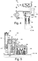
- Figs. 2-5 show an example of the lifting unit 150 of the rotary ultrasonic testing apparatus 100.
- the lifting unit 150 raises and lowers the probe 130 onto and off of the tube 120.
- the lifting unit also maintains the probe 130 in good physical contact with the tube 120 when lowered and in motion.
- Any number of lifting units 150 may be used herein.
- the lifting unit 150 may include a lifting unit base 160, a counterweight mechanism 170, and a hydraulic lifting mechanism 180. Other components and other configurations may be used herein.
- the lifting unit base 160 may be attached to the rotor 140 by conventional means.
- the lifting unit base 160 may include a pair of spring housings 190 and a counterweight rail 200.
- the spring housings 190 may have base extension springs 210 therein. Any number of the base extension springs 210 may be used herein in any suitable size, shape, or configuration.
- the base extension springs 210 may be in communication with the counterweight mechanism 170.
- the counterweight mechanism 170 may maneuver along the counterweight rail 200. Other types of guide mechanism may be used herein with the counterweight mechanism 170. Other components and other configurations may be used herein.
- the counterweight mechanism 170 and the hydraulic lifting mechanism 180 may be positioned about a slider base 220.
- the slider base 220 may be attached to the lifting unit base 160 or otherwise fixably mounted.
- the slider base 220 may include a rotating gear wheel 230.
- the gear wheel 230 may be of conventional design and may have any suitable size, shape, or configuration. Other types of force transmission mechanisms may be used herein. Other components and other configurations may be used herein.
- the counterweight mechanism 170 includes a counterweight 240.
- the counterweight 240 may have any suitable size, shape, or configuration.
- the counterweight 240 may be in communication with the base extension springs 210 on one end and an inner rack 250 on the other.
- the inner rack 250 cooperates with the gear wheel 230 in a rack and pinion configuration.
- the inner rack 250 may have any suitable size, shape, or configuration so as to cooperate with the gear wheel 230.
- Other components and other configurations may be used herein.
- the hydraulic lifting mechanism 180 may include a hydraulic cylinder 260.
- the hydraulic cylinder 260 may be operated by water pressure although other types of working fluids may be used herein.
- the hydraulic cylinder 260 may be of conventional design and may be any suitable size, shape, or configuration.
- the hydraulic cylinder 260 may be attached to the lifting unit base 160 or otherwise fixably mounted.
- the hydraulic cylinder 260 may include a pressure relief valve 270.
- the hydraulic cylinder 260 may drive a piston 280 in reciprocal motion along a first direction with a spring return.
- the water pressure may be about eight (8) bar or so. Other pressures also may be used herein.
- the water pressure may drive the piston 280 so as to compress the internal spring. Releasing this pressure allows the internal spring to drive the return of the piston 280.
- the flow of water may be routed to the hydraulic cylinder 260 via the rotor 140. A portion of the flow of water may be used at a lower pressure to couple the probe 130 to the tube 120.
- the hydraulic lifting mechanism 180 also may include a slider bar 290 positioned for movement along the slider base 220 in the first direction.
- the slider bar 290 may be attached to and support a cam plate 310 for movement therewith.
- the cam plate 310 may include an internal cam guide 320.
- the cam plate 310 also may be in communication with the piston 280 of the hydraulic cylinder 260 via a piston flange 330 for movement therewith in the first direction.
- the slider bar 290 and the cam plate 310 may have any suitable size, shape, or configuration.
- the hydraulic lifting mechanism 180 also may include a cam follower 340 in communication with and supported by the cam plate 310.
- the cam follower 340 may have a slider roller 300 positioned thereon.
- the slider roller 300 may be positioned within the internal cam guide 320 of the cam plate 310. Movement of the cam plate 310 in the first direction causes the slider roller 300 and the cam follower 340 to move in a second direction.
- the first direction and the second direction may be substantially perpendicular to each other.
- the slider roller 300 and the cam follower 340 may have any suitable size, shape, or configuration.
- the cam follower 340 may include an outer rack 350.
- the outer rack 350 may cooperate with the gear wheel 230 in a rack and pinion configuration as described above.
- the outer rack 350 may have any suitable size, shape, or configuration to cooperate with the gear wheel 230.
- the cam follower 340 also includes an outer frame 360 extending from the outer rack 350.
- the outer frame 360 may support a probe shoe 370 therein.
- the probe 130 may be positioned within the probe shoe 370.
- the outer frame 360 and the probe shoe 370 may have any suitable size, shape, or configuration.
- a number of probe extension springs 380 also may connect the floating frame 360 and the probe 130. Any type of extension springs 380 may be used herein. Other components and other configurations may be used herein.
- the hydraulic lifting mechanism 180 of the lifting unit 150 lifts and lowers the probe 130 about the wall of the tube 120. Specifically, retracting the piston 280 of the hydraulic cylinder 260 causes the cam plate 310 to raise the cam follower 340 via the slider roller 300 and the internal cam guide 320 and, hence, to raise the probe 130 off of the tube 120. This upward movement of the cam follower 340 also drives the counterweight mechanism 170 downward via the interaction of the gear wheel 230, the inner rack 250, and the outer rack 350. This downward movement also extends the base extension springs 210.
- This downward force also maintains the contact between the probe 130 and the tube 120.
- the centrifugal force caused by the rotation of the overall rotary ultrasonic testing apparatus 100 generated by the counterweight 240 and the probe 130 generally may be equal.
- the force generated by the base extension springs 210 may be the clamping force maintaining the probe 130 in contact with the tube 120.
- Other components and other configurations may be used herein.
- the lifting units 150 of the rotary ultrasonic testing apparatus 100 thus accurately and efficiently position the probes 130 about the tube 120 or other type of structure. Moreover, the lifting units 150 are comparatively compact and light weight as compared to known units so as to allow the rotary ultrasonic testing apparatus 100 to travel at a higher overall rotational speed while maintaining adequate contact with the tube 120 during an inspection.
- the rotary ultrasonic testing apparatus 100 described herein thus provides ultrasonic testing of the tube 120 and the like in a high speed and efficient manner.
Landscapes
- Chemical & Material Sciences (AREA)
- General Health & Medical Sciences (AREA)
- Life Sciences & Earth Sciences (AREA)
- Health & Medical Sciences (AREA)
- Analytical Chemistry (AREA)
- Biochemistry (AREA)
- Physics & Mathematics (AREA)
- General Physics & Mathematics (AREA)
- Immunology (AREA)
- Pathology (AREA)
- Chemical Kinetics & Catalysis (AREA)
- Electrochemistry (AREA)
- Investigating Or Analyzing Materials By The Use Of Ultrasonic Waves (AREA)
Claims (13)
- Hebeeinrichtung (150) für eine Sonde (130), die in einer Ultraschall-Rotationsprüfvorrichtung (100) verwendet wird, umfassend:eine Hebeeinrichtungsbasis (160);einen Gegengewichtsmechanismus (170);einen hydraulischen Hebemechanismus (180) zum Manövrieren der Sonde (130); undein Zahnrad (230), das zwischen dem Gegengewichtsmechanismus (170) und dem hydraulischen Hebemechanismus (180) positioniert ist,wobei der Gegengewichtsmechanismus (170) eine erste Zahnstange (250) umfasst,wobei der hydraulische Hebemechanismus (180) eine zweite Zahnstange (350) umfasst, und wobei das Zahnrad (230) zwischen der ersten Zahnstange (250) und der zweiten Zahnstange (350) positioniert ist.
- Hebeeinrichtung (150) nach Anspruch 1, wobei die Hebeeinrichtungsbasis (160) eine Basis-Zugfeder (210) umfasst, die an dem Gegengewichtsmechanismus (170) angebracht ist.
- Hebeeinrichtung (150) nach einem der Ansprüche 1 bis 2, wobei der hydraulische Hebemechanismus (180) einen Hydraulikzylinder (260) umfasst.
- Hebeeinrichtung (150) nach Anspruch 3, wobei der hydraulische Hebemechanismus (180) eine Kurvenscheibe (310) umfasst, die mit dem Hydraulikzylinder (260) zum Bewegen in einer ersten Richtung in Verbindung steht.
- Hebeeinrichtung (150) nach Anspruch 4, wobei der hydraulische Hebemechanismus (180) eine Abtastrolle (340) umfasst, die mit der Kurvenscheibe (310) zum Bewegen in eine zweite Richtung in Verbindung steht.
- Hebeeinrichtung (150) nach Anspruch 5, wobei der hydraulische Hebemechanismus (180) eine Prüfkopfsohle (370) umfasst, die an die Abtastrolle (340) zum Manövrieren der Sonde angebracht ist.
- Hebeeinrichtung (150) nach einem der vorstehenden Ansprüche, wobei
die Hebeeinrichtung (150) eine Schieberbasis (220) umfasst, die zwischen dem Gegengewichtsmechanismus (170) und dem hydraulischen Hebemechanismus (180) positioniert ist. - Ultraschall-Rotationsprüfvorrichtung (100) zur Verwendung mit einem Werkstück (110), umfassend:einen Rotor (140);eine Sonde (130); undeine Hebeeinrichtung (150) nach einem der vorstehenden Ansprüche zum Manövrieren der Sonde um das Werkstück (110).
- Rotationsprüfvorrichtung (100) nach Anspruch 8, wobei die Sonde (130) eine Ultraschallsonde umfasst.
- Rotationsprüfvorrichtung (100) nach Anspruch 8 oder 9, ferner umfassend eine Vielzahl von Sonden (130) und
eine Vielzahl von Hebeeinrichtungen (150). - Verfahren zum Manövrieren einer Sonde (130) einer Ultraschall-Rotationsprüfvorrichtung (100) nach einem der Ansprüche 8 bis 10 um ein Werkstück (110), umfassend:Bewegen eines Kolbens (280) eines Hydraulikzylinders (260) in eine erste Richtung;Bewegung einer Kurvenscheibe (310) in die erste Richtung durch den Kolben des Hydraulikzylinders (260);Bewegen einer Abtastrolle (340) in eine zweite Richtung durch die Kurvenscheibe (310);Anheben der Sonde (130) aus dem Werkstück (110) durch die Abtastrolle (340); undAbsenken eines Gegengewichts (240) durch die Abtastrolle (340).
- Verfahren nach Anspruch 11, ferner umfassend die Schritte des Lösens der Kurvenscheibe (310) und Absenkens der Sonde (130) um das Werkstück (110).
- Verfahren nach Anspruch 12, wobei der Schritt des Absenkens der Sonde (130) den Schritt des Absenkens der Kurvenscheibe (310) durch das Gegengewicht (240) umfasst.
Applications Claiming Priority (2)
| Application Number | Priority Date | Filing Date | Title |
|---|---|---|---|
| US13/658,841 US9213017B2 (en) | 2012-10-24 | 2012-10-24 | Rotary ultrasonic testing apparatus with hydraulic lifting units |
| PCT/US2013/066619 WO2014066640A2 (en) | 2012-10-24 | 2013-10-24 | Rotary ultrasonic testing apparatus with hydraulic lifting units |
Publications (2)
| Publication Number | Publication Date |
|---|---|
| EP2912449A2 EP2912449A2 (de) | 2015-09-02 |
| EP2912449B1 true EP2912449B1 (de) | 2020-09-09 |
Family
ID=49841788
Family Applications (1)
| Application Number | Title | Priority Date | Filing Date |
|---|---|---|---|
| EP13811270.1A Active EP2912449B1 (de) | 2012-10-24 | 2013-10-24 | Ultraschall-rotationsvorrichtung mit hydraulischer hebeeinrichtung |
Country Status (6)
| Country | Link |
|---|---|
| US (1) | US9213017B2 (de) |
| EP (1) | EP2912449B1 (de) |
| JP (1) | JP2015536460A (de) |
| CN (1) | CN104755919B (de) |
| CA (1) | CA2887263A1 (de) |
| WO (1) | WO2014066640A2 (de) |
Families Citing this family (5)
| Publication number | Priority date | Publication date | Assignee | Title |
|---|---|---|---|---|
| CN104713951B (zh) | 2013-12-13 | 2018-05-22 | 通用电气公司 | 改进的提降装置以及使用其的超声检测系统 |
| CN106248792A (zh) * | 2016-08-24 | 2016-12-21 | 北京主导时代科技有限公司 | 一种适用于机车车辆轮对检测的半自动化探伤设备 |
| CN108375631B (zh) * | 2018-02-28 | 2021-01-19 | 华南理工大学 | 一种面向绞线结构的液压紧式超声导波损伤检测装置 |
| CN111217296A (zh) * | 2018-11-26 | 2020-06-02 | 厦门厦金机械股份有限公司 | 叉装机卸货装置的旋转驱动机构 |
| KR102236995B1 (ko) * | 2020-11-12 | 2021-04-06 | 주식회사 미래기술 | 와류검사장치 |
Family Cites Families (17)
| Publication number | Priority date | Publication date | Assignee | Title |
|---|---|---|---|---|
| US3077768A (en) | 1957-08-29 | 1963-02-19 | Babcock & Wilcox Co | Weld inspection device support and manipulator |
| GB1005816A (en) | 1960-10-14 | 1965-09-29 | Gkn Group Services Ltd | Improvements relating to methods of and apparatus for the detection of flaws |
| US3582771A (en) * | 1968-09-11 | 1971-06-01 | Amf Inc | Movable inspection device with fluid pressure operated retractors mounted on a rotating member |
| US3553570A (en) | 1969-01-22 | 1971-01-05 | Republic Steel Corp | Automatic billet inspector |
| US3689829A (en) * | 1971-01-13 | 1972-09-05 | Wean Ind Inc | Orbital flaw detector with radially aligned fluid actuators with means to counteract centrifugal forces |
| US3736501A (en) * | 1971-03-25 | 1973-05-29 | Automation Ind Inc | Rotatable test device having diametrically opposed sensors and counterweights interlinked for radial movement by centrifugal force |
| GB1376538A (en) | 1972-03-09 | 1974-12-04 | British Steel Corp | Rotary ultrasonic testing apparatus |
| US3955425A (en) * | 1974-08-16 | 1976-05-11 | Indev, Inc. | Pipe wall thickness gauge |
| US4246794A (en) * | 1979-07-23 | 1981-01-27 | Huntington Alloys, Inc. | Apparatus and method for ultrasonic inspection of round stock such as tubing, pipe and rod |
| US4328708A (en) * | 1980-05-27 | 1982-05-11 | British Steel Corporation | Rotary ultrasonic testing apparatus |
| US4386527A (en) * | 1981-05-04 | 1983-06-07 | E. I. Du Pont De Nemours And Company | Ultrasonic measuring instrument |
| US4718277A (en) | 1985-12-12 | 1988-01-12 | Sound Optics Systems, Inc. | Method and apparatus for characterizing defects in tubular members |
| US4760737A (en) * | 1986-08-29 | 1988-08-02 | The United States Of America As Represented By The United States Department Of Energy | Procedure for flaw detection in cast stainless steel |
| GB8626673D0 (en) | 1986-11-07 | 1986-12-10 | British Steel Corp | Rotary ultrasonic testing apparatus |
| US5313837A (en) | 1991-09-26 | 1994-05-24 | Ico, Inc. | Ultrasonic thickness gage for pipe |
| CN2427808Y (zh) * | 1999-08-10 | 2001-04-25 | 成都金峰科技开发有限责任公司 | 管材超声自动检测装置 |
| US7757559B2 (en) | 2007-05-25 | 2010-07-20 | Magnetic Analysis Corporation | Oblique flaw detection using ultrasonic transducers |
-
2012
- 2012-10-24 US US13/658,841 patent/US9213017B2/en not_active Expired - Fee Related
-
2013
- 2013-10-24 JP JP2015539796A patent/JP2015536460A/ja active Pending
- 2013-10-24 CA CA2887263A patent/CA2887263A1/en not_active Abandoned
- 2013-10-24 CN CN201380055904.8A patent/CN104755919B/zh not_active Expired - Fee Related
- 2013-10-24 EP EP13811270.1A patent/EP2912449B1/de active Active
- 2013-10-24 WO PCT/US2013/066619 patent/WO2014066640A2/en not_active Ceased
Non-Patent Citations (1)
| Title |
|---|
| None * |
Also Published As
| Publication number | Publication date |
|---|---|
| EP2912449A2 (de) | 2015-09-02 |
| CN104755919B (zh) | 2017-12-05 |
| CN104755919A (zh) | 2015-07-01 |
| CA2887263A1 (en) | 2014-05-01 |
| WO2014066640A3 (en) | 2014-08-21 |
| US20140109676A1 (en) | 2014-04-24 |
| WO2014066640A2 (en) | 2014-05-01 |
| JP2015536460A (ja) | 2015-12-21 |
| US9213017B2 (en) | 2015-12-15 |
Similar Documents
| Publication | Publication Date | Title |
|---|---|---|
| EP2912449B1 (de) | Ultraschall-rotationsvorrichtung mit hydraulischer hebeeinrichtung | |
| JP2642370B2 (ja) | 筒状部材の欠陥の特徴を検出する方法、装置及び該装置に於けるトランスデューサ取付装置 | |
| JP5663382B2 (ja) | 非破壊検査のための回転アレイプローブシステム | |
| CN105416436B (zh) | 一种全方位自动焊缝探伤仪驱动装置及其应用 | |
| US8596126B2 (en) | Method and apparatus for a railway wheel ultrasonic testing apparatus | |
| US8596125B2 (en) | Railway wheel ultrasonic testing apparatus | |
| CN102818842A (zh) | 一种变壁厚、变台阶管材超声波自动检测系统 | |
| CN104764423B (zh) | 一种钢管超声测厚装置 | |
| CN119244867B (zh) | 一种石油化工管道腐蚀缺陷检测装置及方法 | |
| CN111398423A (zh) | 一种轴类件超声波无损检测装置 | |
| CN107831216B (zh) | 一种锅炉管道超声波检测装置 | |
| CN104330473A (zh) | 一种变截面轴盘类工件的超声探伤装置 | |
| CN202814933U (zh) | 用于厚壁管材超声波自动检测系统的多通道探头架 | |
| CN204241426U (zh) | 一种变截面轴盘类工件的超声探伤装置 | |
| CN110196285A (zh) | 一种大型环件多面阵列超声自动检测装置及方法 | |
| CN109975411A (zh) | 轴零件批量相控阵超声检测流水线 | |
| CN206740700U (zh) | 一种管棒材夹持驱动装置 | |
| CN106124637B (zh) | 一种用于钻杆水浸超声探伤的三级跟踪装置 | |
| CN201754153U (zh) | 一种自动探伤装置 | |
| CN109975428B (zh) | 线材在线全体积相控阵超声检测装置 | |
| CN210427456U (zh) | 钢管超声波探伤装置的进退料机构 | |
| CN207440013U (zh) | 一种横波超声阵列传感器耦合混凝土板探伤装置 | |
| CN113406203B (zh) | 一种厚壁管材纵向缺陷的检测方法 | |
| CN110018242B (zh) | 一种用于横向裂纹的自动扫查装置 | |
| CN220082487U (zh) | 一种支撑轮组件及隔水管边管扫查器 |
Legal Events
| Date | Code | Title | Description |
|---|---|---|---|
| PUAI | Public reference made under article 153(3) epc to a published international application that has entered the european phase |
Free format text: ORIGINAL CODE: 0009012 |
|
| 17P | Request for examination filed |
Effective date: 20150526 |
|
| AK | Designated contracting states |
Kind code of ref document: A2 Designated state(s): AL AT BE BG CH CY CZ DE DK EE ES FI FR GB GR HR HU IE IS IT LI LT LU LV MC MK MT NL NO PL PT RO RS SE SI SK SM TR |
|
| AX | Request for extension of the european patent |
Extension state: BA ME |
|
| DAX | Request for extension of the european patent (deleted) | ||
| STAA | Information on the status of an ep patent application or granted ep patent |
Free format text: STATUS: EXAMINATION IS IN PROGRESS |
|
| 17Q | First examination report despatched |
Effective date: 20180809 |
|
| GRAP | Despatch of communication of intention to grant a patent |
Free format text: ORIGINAL CODE: EPIDOSNIGR1 |
|
| STAA | Information on the status of an ep patent application or granted ep patent |
Free format text: STATUS: GRANT OF PATENT IS INTENDED |
|
| INTG | Intention to grant announced |
Effective date: 20200414 |
|
| GRAS | Grant fee paid |
Free format text: ORIGINAL CODE: EPIDOSNIGR3 |
|
| GRAA | (expected) grant |
Free format text: ORIGINAL CODE: 0009210 |
|
| STAA | Information on the status of an ep patent application or granted ep patent |
Free format text: STATUS: THE PATENT HAS BEEN GRANTED |
|
| AK | Designated contracting states |
Kind code of ref document: B1 Designated state(s): AL AT BE BG CH CY CZ DE DK EE ES FI FR GB GR HR HU IE IS IT LI LT LU LV MC MK MT NL NO PL PT RO RS SE SI SK SM TR |
|
| REG | Reference to a national code |
Ref country code: GB Ref legal event code: FG4D |
|
| REG | Reference to a national code |
Ref country code: AT Ref legal event code: REF Ref document number: 1312201 Country of ref document: AT Kind code of ref document: T Effective date: 20200915 Ref country code: CH Ref legal event code: EP |
|
| REG | Reference to a national code |
Ref country code: IE Ref legal event code: FG4D |
|
| REG | Reference to a national code |
Ref country code: DE Ref legal event code: R096 Ref document number: 602013072425 Country of ref document: DE |
|
| REG | Reference to a national code |
Ref country code: LT Ref legal event code: MG4D |
|
| PG25 | Lapsed in a contracting state [announced via postgrant information from national office to epo] |
Ref country code: NO Free format text: LAPSE BECAUSE OF FAILURE TO SUBMIT A TRANSLATION OF THE DESCRIPTION OR TO PAY THE FEE WITHIN THE PRESCRIBED TIME-LIMIT Effective date: 20201209 Ref country code: BG Free format text: LAPSE BECAUSE OF FAILURE TO SUBMIT A TRANSLATION OF THE DESCRIPTION OR TO PAY THE FEE WITHIN THE PRESCRIBED TIME-LIMIT Effective date: 20201209 Ref country code: HR Free format text: LAPSE BECAUSE OF FAILURE TO SUBMIT A TRANSLATION OF THE DESCRIPTION OR TO PAY THE FEE WITHIN THE PRESCRIBED TIME-LIMIT Effective date: 20200909 Ref country code: GR Free format text: LAPSE BECAUSE OF FAILURE TO SUBMIT A TRANSLATION OF THE DESCRIPTION OR TO PAY THE FEE WITHIN THE PRESCRIBED TIME-LIMIT Effective date: 20201210 Ref country code: LT Free format text: LAPSE BECAUSE OF FAILURE TO SUBMIT A TRANSLATION OF THE DESCRIPTION OR TO PAY THE FEE WITHIN THE PRESCRIBED TIME-LIMIT Effective date: 20200909 Ref country code: FI Free format text: LAPSE BECAUSE OF FAILURE TO SUBMIT A TRANSLATION OF THE DESCRIPTION OR TO PAY THE FEE WITHIN THE PRESCRIBED TIME-LIMIT Effective date: 20200909 Ref country code: SE Free format text: LAPSE BECAUSE OF FAILURE TO SUBMIT A TRANSLATION OF THE DESCRIPTION OR TO PAY THE FEE WITHIN THE PRESCRIBED TIME-LIMIT Effective date: 20200909 |
|
| REG | Reference to a national code |
Ref country code: AT Ref legal event code: MK05 Ref document number: 1312201 Country of ref document: AT Kind code of ref document: T Effective date: 20200909 |
|
| REG | Reference to a national code |
Ref country code: NL Ref legal event code: MP Effective date: 20200909 |
|
| PG25 | Lapsed in a contracting state [announced via postgrant information from national office to epo] |
Ref country code: LV Free format text: LAPSE BECAUSE OF FAILURE TO SUBMIT A TRANSLATION OF THE DESCRIPTION OR TO PAY THE FEE WITHIN THE PRESCRIBED TIME-LIMIT Effective date: 20200909 Ref country code: RS Free format text: LAPSE BECAUSE OF FAILURE TO SUBMIT A TRANSLATION OF THE DESCRIPTION OR TO PAY THE FEE WITHIN THE PRESCRIBED TIME-LIMIT Effective date: 20200909 Ref country code: PL Free format text: LAPSE BECAUSE OF FAILURE TO SUBMIT A TRANSLATION OF THE DESCRIPTION OR TO PAY THE FEE WITHIN THE PRESCRIBED TIME-LIMIT Effective date: 20200909 |
|
| PG25 | Lapsed in a contracting state [announced via postgrant information from national office to epo] |
Ref country code: PT Free format text: LAPSE BECAUSE OF FAILURE TO SUBMIT A TRANSLATION OF THE DESCRIPTION OR TO PAY THE FEE WITHIN THE PRESCRIBED TIME-LIMIT Effective date: 20210111 Ref country code: NL Free format text: LAPSE BECAUSE OF FAILURE TO SUBMIT A TRANSLATION OF THE DESCRIPTION OR TO PAY THE FEE WITHIN THE PRESCRIBED TIME-LIMIT Effective date: 20200909 Ref country code: SM Free format text: LAPSE BECAUSE OF FAILURE TO SUBMIT A TRANSLATION OF THE DESCRIPTION OR TO PAY THE FEE WITHIN THE PRESCRIBED TIME-LIMIT Effective date: 20200909 Ref country code: RO Free format text: LAPSE BECAUSE OF FAILURE TO SUBMIT A TRANSLATION OF THE DESCRIPTION OR TO PAY THE FEE WITHIN THE PRESCRIBED TIME-LIMIT Effective date: 20200909 Ref country code: EE Free format text: LAPSE BECAUSE OF FAILURE TO SUBMIT A TRANSLATION OF THE DESCRIPTION OR TO PAY THE FEE WITHIN THE PRESCRIBED TIME-LIMIT Effective date: 20200909 Ref country code: CZ Free format text: LAPSE BECAUSE OF FAILURE TO SUBMIT A TRANSLATION OF THE DESCRIPTION OR TO PAY THE FEE WITHIN THE PRESCRIBED TIME-LIMIT Effective date: 20200909 |
|
| REG | Reference to a national code |
Ref country code: DE Ref legal event code: R119 Ref document number: 602013072425 Country of ref document: DE |
|
| PG25 | Lapsed in a contracting state [announced via postgrant information from national office to epo] |
Ref country code: AT Free format text: LAPSE BECAUSE OF FAILURE TO SUBMIT A TRANSLATION OF THE DESCRIPTION OR TO PAY THE FEE WITHIN THE PRESCRIBED TIME-LIMIT Effective date: 20200909 Ref country code: AL Free format text: LAPSE BECAUSE OF FAILURE TO SUBMIT A TRANSLATION OF THE DESCRIPTION OR TO PAY THE FEE WITHIN THE PRESCRIBED TIME-LIMIT Effective date: 20200909 Ref country code: ES Free format text: LAPSE BECAUSE OF FAILURE TO SUBMIT A TRANSLATION OF THE DESCRIPTION OR TO PAY THE FEE WITHIN THE PRESCRIBED TIME-LIMIT Effective date: 20200909 Ref country code: IS Free format text: LAPSE BECAUSE OF FAILURE TO SUBMIT A TRANSLATION OF THE DESCRIPTION OR TO PAY THE FEE WITHIN THE PRESCRIBED TIME-LIMIT Effective date: 20210109 |
|
| REG | Reference to a national code |
Ref country code: CH Ref legal event code: PL |
|
| PG25 | Lapsed in a contracting state [announced via postgrant information from national office to epo] |
Ref country code: LU Free format text: LAPSE BECAUSE OF NON-PAYMENT OF DUE FEES Effective date: 20201024 Ref country code: SK Free format text: LAPSE BECAUSE OF FAILURE TO SUBMIT A TRANSLATION OF THE DESCRIPTION OR TO PAY THE FEE WITHIN THE PRESCRIBED TIME-LIMIT Effective date: 20200909 Ref country code: MC Free format text: LAPSE BECAUSE OF FAILURE TO SUBMIT A TRANSLATION OF THE DESCRIPTION OR TO PAY THE FEE WITHIN THE PRESCRIBED TIME-LIMIT Effective date: 20200909 |
|
| REG | Reference to a national code |
Ref country code: BE Ref legal event code: MM Effective date: 20201031 |
|
| PLBE | No opposition filed within time limit |
Free format text: ORIGINAL CODE: 0009261 |
|
| STAA | Information on the status of an ep patent application or granted ep patent |
Free format text: STATUS: NO OPPOSITION FILED WITHIN TIME LIMIT |
|
| PG25 | Lapsed in a contracting state [announced via postgrant information from national office to epo] |
Ref country code: DE Free format text: LAPSE BECAUSE OF NON-PAYMENT OF DUE FEES Effective date: 20210501 |
|
| 26N | No opposition filed |
Effective date: 20210610 |
|
| GBPC | Gb: european patent ceased through non-payment of renewal fee |
Effective date: 20201209 |
|
| PG25 | Lapsed in a contracting state [announced via postgrant information from national office to epo] |
Ref country code: CH Free format text: LAPSE BECAUSE OF NON-PAYMENT OF DUE FEES Effective date: 20201031 Ref country code: BE Free format text: LAPSE BECAUSE OF NON-PAYMENT OF DUE FEES Effective date: 20201031 Ref country code: DK Free format text: LAPSE BECAUSE OF FAILURE TO SUBMIT A TRANSLATION OF THE DESCRIPTION OR TO PAY THE FEE WITHIN THE PRESCRIBED TIME-LIMIT Effective date: 20200909 Ref country code: LI Free format text: LAPSE BECAUSE OF NON-PAYMENT OF DUE FEES Effective date: 20201031 Ref country code: SI Free format text: LAPSE BECAUSE OF FAILURE TO SUBMIT A TRANSLATION OF THE DESCRIPTION OR TO PAY THE FEE WITHIN THE PRESCRIBED TIME-LIMIT Effective date: 20200909 |
|
| PG25 | Lapsed in a contracting state [announced via postgrant information from national office to epo] |
Ref country code: FR Free format text: LAPSE BECAUSE OF NON-PAYMENT OF DUE FEES Effective date: 20201109 Ref country code: IT Free format text: LAPSE BECAUSE OF FAILURE TO SUBMIT A TRANSLATION OF THE DESCRIPTION OR TO PAY THE FEE WITHIN THE PRESCRIBED TIME-LIMIT Effective date: 20200909 Ref country code: IE Free format text: LAPSE BECAUSE OF NON-PAYMENT OF DUE FEES Effective date: 20201024 |
|
| PG25 | Lapsed in a contracting state [announced via postgrant information from national office to epo] |
Ref country code: GB Free format text: LAPSE BECAUSE OF NON-PAYMENT OF DUE FEES Effective date: 20201209 |
|
| PG25 | Lapsed in a contracting state [announced via postgrant information from national office to epo] |
Ref country code: IS Free format text: LAPSE BECAUSE OF FAILURE TO SUBMIT A TRANSLATION OF THE DESCRIPTION OR TO PAY THE FEE WITHIN THE PRESCRIBED TIME-LIMIT Effective date: 20210109 Ref country code: TR Free format text: LAPSE BECAUSE OF FAILURE TO SUBMIT A TRANSLATION OF THE DESCRIPTION OR TO PAY THE FEE WITHIN THE PRESCRIBED TIME-LIMIT Effective date: 20200909 Ref country code: MT Free format text: LAPSE BECAUSE OF FAILURE TO SUBMIT A TRANSLATION OF THE DESCRIPTION OR TO PAY THE FEE WITHIN THE PRESCRIBED TIME-LIMIT Effective date: 20200909 Ref country code: CY Free format text: LAPSE BECAUSE OF FAILURE TO SUBMIT A TRANSLATION OF THE DESCRIPTION OR TO PAY THE FEE WITHIN THE PRESCRIBED TIME-LIMIT Effective date: 20200909 |
|
| PG25 | Lapsed in a contracting state [announced via postgrant information from national office to epo] |
Ref country code: MK Free format text: LAPSE BECAUSE OF FAILURE TO SUBMIT A TRANSLATION OF THE DESCRIPTION OR TO PAY THE FEE WITHIN THE PRESCRIBED TIME-LIMIT Effective date: 20200909 |