EP2912335B1 - Mechanical devices and method of creating prescribed vibration - Google Patents
Mechanical devices and method of creating prescribed vibration Download PDFInfo
- Publication number
- EP2912335B1 EP2912335B1 EP13785802.3A EP13785802A EP2912335B1 EP 2912335 B1 EP2912335 B1 EP 2912335B1 EP 13785802 A EP13785802 A EP 13785802A EP 2912335 B1 EP2912335 B1 EP 2912335B1
- Authority
- EP
- European Patent Office
- Prior art keywords
- cfg
- vibration profile
- vibratory
- force vector
- mechanical device
- Prior art date
- Legal status (The legal status is an assumption and is not a legal conclusion. Google has not performed a legal analysis and makes no representation as to the accuracy of the status listed.)
- Active
Links
- 238000000034 method Methods 0.000 title claims description 14
- 239000000463 material Substances 0.000 claims description 25
- 230000033001 locomotion Effects 0.000 claims description 24
- 239000013598 vector Substances 0.000 claims description 22
- 230000003044 adaptive effect Effects 0.000 claims description 14
- 230000003287 optical effect Effects 0.000 claims description 4
- 238000005259 measurement Methods 0.000 claims description 3
- 239000002245 particle Substances 0.000 claims description 3
- 230000001939 inductive effect Effects 0.000 claims description 2
- 238000004891 communication Methods 0.000 claims 1
- 239000002002 slurry Substances 0.000 description 5
- 230000004044 response Effects 0.000 description 4
- 230000008859 change Effects 0.000 description 3
- 238000000926 separation method Methods 0.000 description 3
- 230000001360 synchronised effect Effects 0.000 description 3
- 230000006978 adaptation Effects 0.000 description 2
- 238000000418 atomic force spectrum Methods 0.000 description 2
- 239000007788 liquid Substances 0.000 description 2
- 238000012423 maintenance Methods 0.000 description 2
- 239000011159 matrix material Substances 0.000 description 2
- 230000000087 stabilizing effect Effects 0.000 description 2
- 230000001133 acceleration Effects 0.000 description 1
- 230000003373 anti-fouling effect Effects 0.000 description 1
- 238000005056 compaction Methods 0.000 description 1
- 125000004122 cyclic group Chemical group 0.000 description 1
- 238000013016 damping Methods 0.000 description 1
- 238000001514 detection method Methods 0.000 description 1
- 238000001035 drying Methods 0.000 description 1
- 230000002708 enhancing effect Effects 0.000 description 1
- 238000001914 filtration Methods 0.000 description 1
- 239000012530 fluid Substances 0.000 description 1
- 230000007274 generation of a signal involved in cell-cell signaling Effects 0.000 description 1
- 239000008187 granular material Substances 0.000 description 1
- 230000006698 induction Effects 0.000 description 1
- 238000012544 monitoring process Methods 0.000 description 1
- 230000000737 periodic effect Effects 0.000 description 1
- 230000010363 phase shift Effects 0.000 description 1
- 230000010349 pulsation Effects 0.000 description 1
- 238000005086 pumping Methods 0.000 description 1
- 230000009467 reduction Effects 0.000 description 1
- 238000005096 rolling process Methods 0.000 description 1
- 239000007787 solid Substances 0.000 description 1
- 239000003381 stabilizer Substances 0.000 description 1
Images





Classifications
-
- H—ELECTRICITY
- H02—GENERATION; CONVERSION OR DISTRIBUTION OF ELECTRIC POWER
- H02P—CONTROL OR REGULATION OF ELECTRIC MOTORS, ELECTRIC GENERATORS OR DYNAMO-ELECTRIC CONVERTERS; CONTROLLING TRANSFORMERS, REACTORS OR CHOKE COILS
- H02P25/00—Arrangements or methods for the control of AC motors characterised by the kind of AC motor or by structural details
- H02P25/02—Arrangements or methods for the control of AC motors characterised by the kind of AC motor or by structural details characterised by the kind of motor
- H02P25/032—Reciprocating, oscillating or vibrating motors
-
- B—PERFORMING OPERATIONS; TRANSPORTING
- B06—GENERATING OR TRANSMITTING MECHANICAL VIBRATIONS IN GENERAL
- B06B—METHODS OR APPARATUS FOR GENERATING OR TRANSMITTING MECHANICAL VIBRATIONS OF INFRASONIC, SONIC, OR ULTRASONIC FREQUENCY, e.g. FOR PERFORMING MECHANICAL WORK IN GENERAL
- B06B1/00—Methods or apparatus for generating mechanical vibrations of infrasonic, sonic, or ultrasonic frequency
- B06B1/10—Methods or apparatus for generating mechanical vibrations of infrasonic, sonic, or ultrasonic frequency making use of mechanical energy
- B06B1/16—Methods or apparatus for generating mechanical vibrations of infrasonic, sonic, or ultrasonic frequency making use of mechanical energy operating with systems involving rotary unbalanced masses
- B06B1/161—Adjustable systems, i.e. where amplitude or direction of frequency of vibration can be varied
Definitions
- Some mechanical devices perform specific functions through use of induced vibratory motion. Such devices include monitoring damage detection and structural assessment of civil structures and mechanical devices, damping in civil structures, searching for oil and gas with seismic impulse exciters, medical device and equipment, controlling fluid flow in a pipe, deliquifying screens, material separators, vibratory feeders and conveyors, attrition mills, mold shakeout machines, and vibratory compactors.
- these devices utilize one or more force generators to create a predefined force profile for inducing vibration within the device.
- These force generators may include linear drives or imbalanced rotors driven by synchronous motors or induction motors whose speed is an integer fraction of the electrical source frequency. To vary the frequency of vibration, variable frequency drives (VFDs) are used in conjunction with these motors.
- VFDs variable frequency drives
- springs, stabilizers, and/or mechanical pivots are used.
- multiple synchronous or asynchronous motors are used on the same device and are coupled through common base vibration, they tend to synchronize with each other to produce a consistent and predesigned force profile.
- the aforementioned devices are incapable of maintaining a desired vibration profile when operating conditions change, such as a change in material loading, changes in temperature, changes in material properties, or other variables that can alter the response of the mechanical device.
- the aforementioned devices cannot create certain desirable vibration profiles.
- the aforementioned devices cannot create a variety of selectable vibration profiles within limits imposed by the authority of their respective force generators.
- United States Patent No. US 5,202,824A discloses an apparatus for stabilizing the operation of rotational machinery, particularly machinery which uses magnetic bearings. Accelerometers sense various vibrations within the machinery. The outputs of the accelerometers are analyzed by a Fast Fourier Transform algorithm and multiplied by an array of influence coefficients to calculate desired stabilizing forces to be applied to the rotating machinery. Compensating analog voltage signals are generated in accordance therewith and transmitted to magnetic control coils within the rotating machinery.
- United States Patent No. US 4,950,966A discloses a method and apparatus for cancelling vibrations caused by periodic pulsating forces acting on a rotating shaft which are synchronous with the shaft rotation.
- An adaptive algorithm is implemented which utilizes the sensed velocity or acceleration of the difference between the pulsing forces acting on the shaft and an applied control force to generate an estimate of the phase shift existing therebetween to adjust a pair of adaptive weighting coefficients for sine and cosine force components which are adjusted by a least mean square (LMS) algorithm.
- LMS least mean square
- Actuating signals for the reaction mass actuator are generated from the weighted force components which applies a controlled force to the shaft to oppose the shaft pulsation force and thus cancel the vibration.
- WO00/39480A1 discloses a system for enhancing vibration reduction in a vehicle that utilizes one or more sensors which sense ambient vibration in the vehicle and generate a signal corresponding to the sensed vibrations.
- a control circuit is coupled to the sensors and receives the signals.
- the control circuit utilizing Kalman filtering algorithms, generates a control signal that adapts a previous command force, from an actuator to a sensor, thereby dynamically updating a parameter that represents an estimated vehicle response.
- This dynamically updated parameter is a result of utilizing a covariance that is a function of an empirically derived constant value and a change in forces exerted by the actuator.
- the control circuit outputs this control signal to vibration generator units, which generate a vibration field for reducing vibrations in the vehicle.
- United States Patent No. US 4,999,534A discloses an apparatus for cancellation of vibrations in a device.
- a first matrix combines the vibration signals from a plurality of locations to produce mode signals indicative of individual modes of vibration of said device.
- An adaptive element in response to said mode signals generates mode vibration attenuation signals corresponding to said mode signals.
- a second matrix combines the mode vibration attenuation signals to produce vibration attenuation signals for generating vibration attenuation forces.
- WO99/17275A1 discloses an adaptive control system implements a back-projection technique to limit adaptation of adaptive parameters in the system so that system actuators are not driven beyond desired physical limitations.
- adaptation is back-projected onto or near a smooth convex surface defining the edge of the desired region.
- United Kingdom Patent No. GB 2,331,164A discloses an adaptive control method employs an adaptive signal generation algorithm for generating an adaptive signal which cancels a cyclic signal at a measurement point, and an adaptive coefficient vector renewing algorithm for renewing the amplitudes and phases of the adaptive signal.
- the invention described herein is applicable to a wide range of devices where a mechanically induced vibration is desired, the non-limiting examples of vibratory deliquifying machines, conveyors, and separators are used for illustration purposes.
- FIG. 1 shows the invention as applied to the non-limiting example of a vibratory deliquifying machine illustrated and generally designated by the numeral 10.
- the non-limiting example vibratory deliquifying machine 10 as illustrated, includes inlet 12, screen 14, exit 16, springs 18, and force generators 20.
- Force generators 20 are preferably CFG 20.
- slurries enter inlet 12 where a vibratory motion causes the slurry to convey across screen 14 suspended on springs 18. As the slurry is conveyed across screen 14, liquid passes through screen 14 while dry material (not shown) is extracted at exit 16.
- Existing vibratory deliquifying machines 10 have a specific elliptical vibratory motion at one specific frequency providing for optimal performance.
- CFG 20, including controller 22, enables the use of a prescribed elliptical vibratory motion for optimal performance.
- the prescribed elliptical vibratory motion from CFGs 20 increases the separation of liquid and solid matter. This also enables the maintenance of the optimal vibratory motion even when the mass of the slurry or the center-of-gravity of the slurry on screen 14 changes with time or operating condition.
- CFGs 20 are mounted to screen structure 24 of vibratory deliquifying machine 10.
- each CFG 20 is capable of creating rotating force vector 26 having a controllable magnitude F 0 , a controllable phase ⁇ , and a controllable frequency co.
- CFGs 20 are mounted on centerline 28 of vibratory deliquifying machine 10. This placement avoids creating a side-to-side rocking motion from applied forces.
- Screen structure 24 is assumed to be a rigid body, whereby the two proximal CFGs 20 create two degrees-of-freedom of controllable planar motion.
- the addition of more CFGs 20 will increase the degrees-of-freedom of controllable motion.
- the application of a third CFG 20 will allow for three degrees-of-freedom of controllable planar motion.
- the maximum of six CFGs 20 will allow for a full six degrees-of-freedom rigid body control of motion.
- two-to-six CFGs 20 are utilized on a rigid body to create controllable motion from two to six two degrees-of-freedom, respectively.
- sensors 30 are used to provide input to controller 22. Sensors 30 are applied to the screen structure 24. The location of sensors 30 is determined by the particular data element being sensed. Sensors 30 monitor an aspect of vibratory deliquifying machine 10 performance related to the induced vibratory motion.
- controller 22 commands the force magnitude, phase, and frequency of each CFG 20.
- Controller 22 resides at least one algorithm comparing performance, as measured by sensors 30, with a desired performance to produce an error. The algorithm then produces CFG commands that that will reduce or minimize this error.
- controller 22 uses a filtered-x least mean square (Fx-LMS) gradient descent algorithm to reduce the error.
- Fx-LMS filtered-x least mean square
- TAG time-average gradient
- Sensors include all types of vibration sensors, including digital, analog, and optical. Sensors also include accelerometers, thermocouples, infrared sensors, mass flow rate sensors, particle matter sensors, load sensors and optical sensors. The sensors may be selected from the group consisting of vibration sensors, accelerometers, thermocouples, infrared sensors, mass flow rate sensors, particle matter sensors, load sensors, optical sensors and combinations thereof. A plurality of sensors of the same type or a plurality of different types sensors are employed to maximize the measurement of the operating condition.
- the mechanical devices contemplated herein perform specific operating functions through use of induced vibratory profiles. Operating functions material flow or movement, material separation, material compaction, drying, pumping, as well as others. All of the operating functions are enabled by the induced vibratory profile and react to vibratory input from CFGs 20.
- sensors 30 are accelerometers directly measuring the operating function of screen structure 24.
- the operating condition measured is the vibration profile of screen structure 24.
- Controller 22 implements an algorithm that produces CFG commands such that the measured operating function moves toward the prescribed vibration profile reducing the error.
- FIG. 2 shows both a prescribed vibration profile (labeled as "Command") and a measured vibration profile as measured by a biaxial accelerometer located near the center-of-gravity of the screen assembly.
- the prescribed vibration profile is illustrated as a solid line and labeled as "Command”
- the measured vibration profile is illustrated as a dotted line and labeled as "Measured.” It can be seen that the difference, or error, between these profiles is small.
- FIG. 3 shows the present invention applied to vibratory feeder 100.
- Material is fed onto feeder bed 102 of vibratory feeder 100 from hopper 104.
- Vibratory motion conveys the material along feeder bed 102 where it is then metered into another machine, or a package, or any one of a number of secondary systems.
- Optimal performance includes precision metering of material flow or high material conveyance rate without damaging or dispersing the material.
- the present invention also enables the maintenance of the optimal vibratory motion even when the mass of the material on feeder bed 102 or the center-of-gravity of the material on feeder bed 102 changes with time or operating condition.
- the prescribed vibration is selected from the group consisting of linear, elliptical and orbital, as determined by the desired outcome.
- Vibratory feeder 100 illustrated in FIG. 3 is used similarly to the application to vibratory deliquifying machine 10 described hereinabove and illustrated in FIGS. 1 and 2 .
- Feedback sensors 106 shown are accelerometers, but may be sensors 106 that directly or indirectly measure material flow rate.
- sensors 106 shown in FIG. 3 are embedded within CFG 20 thereby eliminating extra connectors and wiring harnesses associated therewith.
- vibratory material separator 200 is illustrated as another non-limiting example.
- Vibratory material separator 200 uses screens (not shown) and induced vibratory motion to separate granular materials or aggregates based on grain size and/or density.
- the performance of material separators is optimized.
- Optimal performance includes improving separation, or improving throughput, or a combination thereof.
- Optimal performance also includes enhancement of the screen life and antifouling of the screen. The optimal vibratory motion is maintained even when the mass of the material or the center-of-gravity of the material within vibratory material separator 200 changes with time or operating condition.
- the application of the present invention to vibratory material separator 200 illustrated in FIG. 4 is very similar to the application to previous examples described hereinbefore.
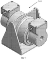
- FIGS. 5A-8C provide non-limiting examples of CFG 20 in different variations.
- CFG 20 consists of two imbalanced masses 32a, 32b each attached to a shaft 34 and each suspended between two rolling element bearings 36a, 36b.
- Each imbalance mass 32a, 32b is driven by motor 38a, 38b.
- the two motors 38a, 38b within CFG 20 are brushless permanent magnet motors, sometimes called servo motors.
- Each motor 38a, 38b includes a sensor 40 for sensing the rotary position of imbalanced masses 32a, 32b.
- Equation (1) receives the rotary position sensor feedback, and uses common servo motor control techniques controls the rotary position ⁇ of each motor.
- Rotational phase ⁇ corresponds to the phase of the motor (and thus the imbalanced mass) with respect to an internal reference tachometer signal.
- a zero-force case and a full-force case of imbalance masses 32a and 32b of CFG 20 are both illustrated.
- the relative phase ⁇ 2 - ⁇ 1 is 180 degrees and resulting force rotating vector 26 has a magnitude of zero.
- the relative phase ⁇ 2 - ⁇ 1 is 0 degrees and resulting rotating force vector 26 has a maximum magnitude of 21FI.
- the magnitude of resulting rotating force vector 26 will be between zero and maximum.
- the collective phase ⁇ of rotating force vector 26 can be varied to provide phasing between CFGs 20. Through control of phase ⁇ of each imbalance mass 32a, 32b the magnitude and absolute phase of the rotating force vector 26 produced by CFG 20 can be controlled.
- the particular structure carrying CFGs 20 includes n vibration sensors 30 and m CFGs 20, wherein n ⁇ m and (with m whole number equal to or greater than one). Controller 22 detects at least one vibration signal from at least one vibration sensor 30, the vibration signal providing a magnitude, a phase, and a frequency of the detected vibration. Controller 22 generates a vibration reference signal from the detected vibration data and correlates it to the relative vibration of the particular structure carrying CFGs 20 relative to the CFGs 20.
- the first CFG 20 includes the first imbalance mass 32a controllably driven about a first mass axis 42 with a first controllable imbalance phase ⁇ 1 and a second imbalance mass 32b controllably driven about a second mass axis 44 with a second controllable imbalance phase ⁇ 2 , the first controllable imbalance phase ⁇ 1 and the imbalance phase ⁇ 2 controlled in reference to the vibration reference signal.
- the m th CFG 20 includes a first imbalance mass (mass m_1 ) 32a controllably driven about a first mass axis 42 with a first controllable imbalance phase and a second imbalance mass 32b controllably driven about a second mass axis 44 with a second controllable imbalance phase, the imbalance phase and the imbalance phase controlled in reference to the vibration reference signal.
- the vibration reference signal is typically an artificially generated signal within the controller and is typically a sine wave at the desired operational frequency.
- CFG 20 includes a first imbalance mass 32a with a first controllable imbalance phase ⁇ 1 and a second imbalance mass 32b with a second controllable imbalance phase ⁇ 2 .
- the first imbalance mass 32a is driven with first motor 38a and second imbalance mass 32b is driven with second motor 38b.
- FIGS. 6 and 7 an embodiment implementing CFG 20 as two identical, but separate, units 46 is illustrated.
- Each unit 46 contains a single imbalanced mass 32 driven by a single motor 38. By positioning the two units 46 in close proximity, the functionality of CFG 20 is achieved.
- FIGS. 6 and 7 show additional embodiments of CFG 20. In these figures, only one of two units 46 comprising CFG 20 is shown. The same basic elements previously described are identified in the embodiments shown in FIGS. 6 and 7 .
- Two units 46 may be applied to a mechanical device in proximity to one another to enable CFG 20. For example, two units 46 may be applied coaxially on either side of mounting plate to enable CFG 20 as illustrated in FIG. 9 . In another example illustrated in FIG. 10 , two units 46 are mounted non-coaxially side-by-side to enable CFG 20.
Landscapes
- Engineering & Computer Science (AREA)
- Power Engineering (AREA)
- Mechanical Engineering (AREA)
- Apparatuses For Generation Of Mechanical Vibrations (AREA)
Description
- Some mechanical devices perform specific functions through use of induced vibratory motion. Such devices include monitoring damage detection and structural assessment of civil structures and mechanical devices, damping in civil structures, searching for oil and gas with seismic impulse exciters, medical device and equipment, controlling fluid flow in a pipe, deliquifying screens, material separators, vibratory feeders and conveyors, attrition mills, mold shakeout machines, and vibratory compactors. Typically these devices utilize one or more force generators to create a predefined force profile for inducing vibration within the device. These force generators may include linear drives or imbalanced rotors driven by synchronous motors or induction motors whose speed is an integer fraction of the electrical source frequency. To vary the frequency of vibration, variable frequency drives (VFDs) are used in conjunction with these motors. To tailor the shape of the vibration profile or create a resonance for the purpose of amplifying the vibration response, springs, stabilizers, and/or mechanical pivots are used. When multiple synchronous or asynchronous motors are used on the same device and are coupled through common base vibration, they tend to synchronize with each other to produce a consistent and predesigned force profile.
- The aforementioned devices are incapable of maintaining a desired vibration profile when operating conditions change, such as a change in material loading, changes in temperature, changes in material properties, or other variables that can alter the response of the mechanical device. In some cases, the aforementioned devices cannot create certain desirable vibration profiles. In other cases, the aforementioned devices cannot create a variety of selectable vibration profiles within limits imposed by the authority of their respective force generators.
- United States Patent No.
US 5,202,824A discloses an apparatus for stabilizing the operation of rotational machinery, particularly machinery which uses magnetic bearings. Accelerometers sense various vibrations within the machinery. The outputs of the accelerometers are analyzed by a Fast Fourier Transform algorithm and multiplied by an array of influence coefficients to calculate desired stabilizing forces to be applied to the rotating machinery. Compensating analog voltage signals are generated in accordance therewith and transmitted to magnetic control coils within the rotating machinery. - United States Patent No.
US 4,950,966A discloses a method and apparatus for cancelling vibrations caused by periodic pulsating forces acting on a rotating shaft which are synchronous with the shaft rotation. An adaptive algorithm is implemented which utilizes the sensed velocity or acceleration of the difference between the pulsing forces acting on the shaft and an applied control force to generate an estimate of the phase shift existing therebetween to adjust a pair of adaptive weighting coefficients for sine and cosine force components which are adjusted by a least mean square (LMS) algorithm. Actuating signals for the reaction mass actuator are generated from the weighted force components which applies a controlled force to the shaft to oppose the shaft pulsation force and thus cancel the vibration. - International Publication No.
WO00/39480A1 - United States Patent No.
US 4,999,534A discloses an apparatus for cancellation of vibrations in a device. A first matrix combines the vibration signals from a plurality of locations to produce mode signals indicative of individual modes of vibration of said device. An adaptive element in response to said mode signals generates mode vibration attenuation signals corresponding to said mode signals. A second matrix combines the mode vibration attenuation signals to produce vibration attenuation signals for generating vibration attenuation forces. - International Publication No.
WO99/17275A1 - United Kingdom Patent No.
GB 2,331,164A - In accordance with a first aspect of the present invention there is provided a system for creating a prescribed operating function within a mechanical device as recited in claim 1.
- In accordance with a second aspect of the present invention there is provided a method for creating a prescribed operating function on a mechanical device as recited in
claim 10. - Numerous objects and advantages of the invention will become apparent as the following detailed description of the preferred embodiments is read in conjunction with the drawings, which illustrate such embodiments.
-
-
FIG. 1 illustrates a perspective view of a deliquifying screen with circular force generators positioned thereon. -
FIG. 2 illustrates a typical vibration prescribed vibration profile enabled by the present invention. -
Fig. 3 illustrates a perspective view of a vibratory conveyor with circular force generators positioned thereon. -
FIG. 4 illustrates a perspective view of a vibratory material separator with circular force generators positioned thereon. -
FIG. 5A illustrates one embodiment of a Circular Force Generator (CFG). -
FIG. 5B illustrates a partial cut-away view of the CFG ofFIG. 5A . -
FIG. 6 illustrates another embodiment of a CFG. In this case the CFG comprises two separate identical components, one of which is shown. -
FIG. 7 illustrates yet another embodiment of a CFG. In this case the CFG comprises two separate identical components, one of which is shown. -
FIGS. 8A-C illustrate force generation using two co-rotating imbalanced rotors to create a circular force with controllable magnitude and phase, thereby providing a CFG. -
FIG. 9 illustrates two CFGs coaxial mounted on both sides of a mounting plate. -
FIG. 10 illustrates two CFGs mounted side-by-side on a mounting plate. - The invention described herein is applicable to a wide range of devices where a mechanically induced vibration is desired, the non-limiting examples of vibratory deliquifying machines, conveyors, and separators are used for illustration purposes.
- Referring to the drawings,
FIG. 1 shows the invention as applied to the non-limiting example of a vibratory deliquifying machine illustrated and generally designated by thenumeral 10. The non-limiting example vibratory deliquifyingmachine 10, as illustrated, includesinlet 12,screen 14,exit 16,springs 18, andforce generators 20.Force generators 20 are preferablyCFG 20. - In vibratory
deliquifying machine 10, slurries (not shown) enterinlet 12 where a vibratory motion causes the slurry to convey acrossscreen 14 suspended onsprings 18. As the slurry is conveyed acrossscreen 14, liquid passes throughscreen 14 while dry material (not shown) is extracted atexit 16. - Existing
vibratory deliquifying machines 10 have a specific elliptical vibratory motion at one specific frequency providing for optimal performance.CFG 20, includingcontroller 22, enables the use of a prescribed elliptical vibratory motion for optimal performance. In the case of the non-limiting example ofvibratory deliquifying machine 10, the prescribed elliptical vibratory motion fromCFGs 20 increases the separation of liquid and solid matter. This also enables the maintenance of the optimal vibratory motion even when the mass of the slurry or the center-of-gravity of the slurry onscreen 14 changes with time or operating condition. - In
FIG. 1 two,CFGs 20 are mounted to screenstructure 24 ofvibratory deliquifying machine 10. Referring toFIGS. 8A-8C forCFG 20, eachCFG 20 is capable of creatingrotating force vector 26 having a controllable magnitude F0, a controllable phase ϕ, and a controllable frequency co. TwoCFGs 20 operating at the same frequency ω and proximal to each other, as shown inFIGS. 1 and8A-8C , where one is producing a clockwise rotating force vector and one is producing a counter clockwise rotating force vector, produce a resultant that is a controllable two degree-of-freedom planar force. These applied forces act onscreen structure 24 and produce an induced vibratory motion. - In the non-limiting example illustrated in
FIG. 1 ,CFGs 20 are mounted oncenterline 28 ofvibratory deliquifying machine 10. This placement avoids creating a side-to-side rocking motion from applied forces.Screen structure 24 is assumed to be a rigid body, whereby the twoproximal CFGs 20 create two degrees-of-freedom of controllable planar motion. The addition of more CFGs 20 will increase the degrees-of-freedom of controllable motion. For example, the application of athird CFG 20 will allow for three degrees-of-freedom of controllable planar motion. The maximum of sixCFGs 20 will allow for a full six degrees-of-freedom rigid body control of motion. Depending upon the need, two-to-sixCFGs 20 are utilized on a rigid body to create controllable motion from two to six two degrees-of-freedom, respectively. - In the non-limiting example of
vibratory deliquifying machine 10 illustrated inFIG. 1 ,sensors 30 are used to provide input tocontroller 22.Sensors 30 are applied to thescreen structure 24. The location ofsensors 30 is determined by the particular data element being sensed.Sensors 30 monitor an aspect ofvibratory deliquifying machine 10 performance related to the induced vibratory motion. - The signals from
sensors 30 are received bycontroller 22.Controller 22 commands the force magnitude, phase, and frequency of eachCFG 20. Withincontroller 22 resides at least one algorithm comparing performance, as measured bysensors 30, with a desired performance to produce an error. The algorithm then produces CFG commands that that will reduce or minimize this error. Many methods are known to those skilled in the art for reducing an error based onsensor 30 feedback, including various feedback control algorithms, open-loop adaptive algorithms, and non-adaptive open-loop methods. In one exemplary embodiment,controller 22 uses a filtered-x least mean square (Fx-LMS) gradient descent algorithm to reduce the error. In another exemplary embodiment, the controller uses a time-average gradient (TAG) algorithm to reduce the error. - Sensors include all types of vibration sensors, including digital, analog, and optical. Sensors also include accelerometers, thermocouples, infrared sensors, mass flow rate sensors, particle matter sensors, load sensors and optical sensors. The sensors may be selected from the group consisting of vibration sensors, accelerometers, thermocouples, infrared sensors, mass flow rate sensors, particle matter sensors, load sensors, optical sensors and combinations thereof. A plurality of sensors of the same type or a plurality of different types sensors are employed to maximize the measurement of the operating condition.
- The mechanical devices contemplated herein perform specific operating functions through use of induced vibratory profiles. Operating functions material flow or movement, material separation, material compaction, drying, pumping, as well as others. All of the operating functions are enabled by the induced vibratory profile and react to vibratory input from
CFGs 20. - In an exemplary embodiment,
sensors 30 are accelerometers directly measuring the operating function ofscreen structure 24. In this non-limiting embodiment, the operating condition measured is the vibration profile ofscreen structure 24. Withincontroller 22 the measured operating function is compared with a desired or prescribed vibration profile to produce an error.Controller 22 then implements an algorithm that produces CFG commands such that the measured operating function moves toward the prescribed vibration profile reducing the error. By way of illustration,FIG. 2 shows both a prescribed vibration profile (labeled as "Command") and a measured vibration profile as measured by a biaxial accelerometer located near the center-of-gravity of the screen assembly. InFIG. 2 the prescribed vibration profile is illustrated as a solid line and labeled as "Command," and the measured vibration profile is illustrated as a dotted line and labeled as "Measured." It can be seen that the difference, or error, between these profiles is small. - In another illustrative non-limiting example,
FIG. 3 shows the present invention applied tovibratory feeder 100. Material is fed ontofeeder bed 102 ofvibratory feeder 100 fromhopper 104. Vibratory motion conveys the material alongfeeder bed 102 where it is then metered into another machine, or a package, or any one of a number of secondary systems. - Application of the present invention enables a prescribed elliptical vibratory motion for optimal performance of
vibratory feeder 100. Optimal performance includes precision metering of material flow or high material conveyance rate without damaging or dispersing the material. The present invention also enables the maintenance of the optimal vibratory motion even when the mass of the material onfeeder bed 102 or the center-of-gravity of the material onfeeder bed 102 changes with time or operating condition. In other embodiments or other uses the prescribed vibration is selected from the group consisting of linear, elliptical and orbital, as determined by the desired outcome. -
Vibratory feeder 100 illustrated inFIG. 3 is used similarly to the application tovibratory deliquifying machine 10 described hereinabove and illustrated inFIGS. 1 and 2 .Feedback sensors 106 shown are accelerometers, but may besensors 106 that directly or indirectly measure material flow rate. By way of non-limiting example,sensors 106 shown inFIG. 3 are embedded withinCFG 20 thereby eliminating extra connectors and wiring harnesses associated therewith. - Referring to
FIG. 4 vibratory material separator 200 is illustrated as another non-limiting example.Vibratory material separator 200, as illustrated, uses screens (not shown) and induced vibratory motion to separate granular materials or aggregates based on grain size and/or density. Using prescribed vibratory motion generated byCFGs 20, the performance of material separators is optimized. Optimal performance includes improving separation, or improving throughput, or a combination thereof. Optimal performance also includes enhancement of the screen life and antifouling of the screen. The optimal vibratory motion is maintained even when the mass of the material or the center-of-gravity of the material withinvibratory material separator 200 changes with time or operating condition. The application of the present invention tovibratory material separator 200 illustrated inFIG. 4 is very similar to the application to previous examples described hereinbefore. -
FIGS. 5A-8C provide non-limiting examples ofCFG 20 in different variations. Referring toFIGS. 5A-6 , ,CFG 20 consists of twoimbalanced masses shaft 34 and each suspended between two rollingelement bearings imbalance mass motor motors CFG 20 are brushless permanent magnet motors, sometimes called servo motors. Eachmotor sensor 40 for sensing the rotary position ofimbalanced masses aforementioned controller 22, an algorithm employing Equation (1) that receives the rotary position sensor feedback, and uses common servo motor control techniques controls the rotary position θ of each motor. The equation employed is illustrated by Equation (1):
imbalanced masses imbalanced mass 
imbalanced mass imbalanced mass 32a with respect to the secondimbalanced mass 32b (i.e., the relative phase) withinCFG 20 will determine the magnitude of resultantrotating force vector 26. - Referring to
FIGS. 8A-C , a zero-force case and a full-force case ofimbalance masses CFG 20 are both illustrated. In the zero-force case the relative phase ϕ2-ϕ1 is 180 degrees and resultingforce rotating vector 26 has a magnitude of zero. In the full-force case, the relative phase ϕ2-ϕ1 is 0 degrees and resultingrotating force vector 26 has a maximum magnitude of 21FI. For relative phases ϕ2-ϕ1 between 0 and 180 degrees, the magnitude of resultingrotating force vector 26 will be between zero and maximum. Furthermore, the collective phase γ of rotatingforce vector 26 can be varied to provide phasing betweenCFGs 20. Through control of phase φ of eachimbalance mass rotating force vector 26 produced byCFG 20 can be controlled. - Referring to
FIGS. 1-8C , the particularstructure carrying CFGs 20 includesn vibration sensors 30 andm CFGs 20, wherein n≥m and (with m whole number equal to or greater than one).Controller 22 detects at least one vibration signal from at least onevibration sensor 30, the vibration signal providing a magnitude, a phase, and a frequency of the detected vibration.Controller 22 generates a vibration reference signal from the detected vibration data and correlates it to the relative vibration of the particularstructure carrying CFGs 20 relative to theCFGs 20. - Preferably, the
first CFG 20 includes thefirst imbalance mass 32a controllably driven about a firstmass axis 42 with a first controllable imbalance phase ϕ1 and asecond imbalance mass 32b controllably driven about a secondmass axis 44 with a second controllable imbalance phase ϕ2, the first controllable imbalance phase ϕ1 and the imbalance phase ϕ2 controlled in reference to the vibration reference signal. The mth CFG 20 includes a first imbalance mass (massm_1) 32a controllably driven about a firstmass axis 42 with a first controllable imbalance phase and asecond imbalance mass 32b controllably driven about a secondmass axis 44 with a second controllable imbalance phase, the imbalance phase and the imbalance phase controlled in reference to the vibration reference signal. The vibration reference signal is typically an artificially generated signal within the controller and is typically a sine wave at the desired operational frequency. - Referring to
FIGS. 5A-8 ,CFG 20 includes afirst imbalance mass 32a with a first controllable imbalance phase ϕ1 and asecond imbalance mass 32b with a second controllable imbalance phase ϕ2. Thefirst imbalance mass 32a is driven withfirst motor 38a andsecond imbalance mass 32b is driven withsecond motor 38b. - Referring to
FIGS. 6 and7 , anembodiment implementing CFG 20 as two identical, but separate, units 46 is illustrated. Each unit 46 contains a singleimbalanced mass 32 driven by asingle motor 38. By positioning the two units 46 in close proximity, the functionality ofCFG 20 is achieved.FIGS. 6 and7 show additional embodiments ofCFG 20. In these figures, only one of two units 46 comprisingCFG 20 is shown. The same basic elements previously described are identified in the embodiments shown inFIGS. 6 and7 . Two units 46 may be applied to a mechanical device in proximity to one another to enableCFG 20. For example, two units 46 may be applied coaxially on either side of mounting plate to enableCFG 20 as illustrated inFIG. 9 . In another example illustrated inFIG. 10 , two units 46 are mounted non-coaxially side-by-side to enableCFG 20. - Other embodiments of the current invention will be apparent to those skilled in the art from a consideration of this specification or practice of the invention disclosed herein. Thus, the foregoing specification is considered merely exemplary of the current invention with the true scope thereof being defined by the following claims.
Claims (15)
- A system for creating a prescribed vibration profile within a mechanical device comprising:a mechanical device;at least one circular force generator (CFG) (20) affixed to the mechanical device, the CFG (20) capable of producing a rotating force vector, wherein the rotating force vector includes a magnitude, a phase, and a frequency;at least one sensor (30) positioned on the mechanical device;at least one vibration profile in the mechanical device created by the CFG (20), wherein the sensor (30) measures the at least one vibration profile;a controller (22) in electronic communication with the sensor (30) and with the CFG (20), characterized in thatthe controller (22) operably controls the rotating force vector based upon the measurement of the vibration profile, wherein the magnitude, phase and frequency are independently controllable by the controller (22), wherein the controller (22) changes the rotating force vector such that a difference between the measured vibration profile and a prescribed vibration profile is reduced.
- The system of claim 1, wherein the CFG (20) further comprises two imbalanced masses (32a, 32b) independently rotated by two motors (38a, 38b).
- The system of claim 1, further comprising a second CFG (20), the second CFG (20) operating at the same frequency as the CFG (20).
- The system of claim 3, wherein one of the CFGs (20) produces the rotating force vector in a clockwise direction and the other CFG (20) produces the rotating force vector in a counter clockwise direction, wherein the combination of the two rotating force vectors produce a resultant force vector that is controllable in two degree-of-freedom, the resultant force vector inducing a vibratory motion in the mechanical device and creating the prescribed vibration profile.
- The system of claim 4, wherein the prescribed vibration profile is an elliptical vibratory motion at one specific frequency.
- The system of claim 1, wherein the prescribed vibration profile is selected from the group consisting of linear, elliptical and orbital motions.
- The system of claim 1 wherein the sensor (30) is an accelerometer.
- The system of claim 1 wherein the sensor (30) is a plurality of accelerometers.
- The system of claim 8 wherein said accelerometers are co-located with said CFG (20).
- A method for creating a prescribed vibration profile on a mechanical device having at least one CFG (20) capable of producing a rotating force vector with a controllable magnitude, phase and frequency, a sensor (30) and a controller (22), and the CFG (20) capable of creating at least one vibration profile in the mechanical device the method characterized by the steps of:defining a prescribed vibration profile;measuring a vibration profile with the sensor (30) being a measured vibration profile;communicating the measured vibration profile from the sensor (30) to the controller (22);calculating an error by comparing the measured vibration profile to the prescribed vibration profile;processing the error in the controller (22) using an algorithm, wherein the processing produces a command for the CFG (20), the command including changes to the magnitude, the phase, and/or the frequency of the rotating force vector of the CFG; andcommunicating the changes to the rotating force vector to the CFG (20) such that the difference between the measured vibration profile and the prescribed vibration profile is reduced.
- A method of claim 10, further comprising the step of using a feedback control algorithm, an open-loop adaptive algorithm, a non-adaptive open-loop algorithm, a filtered-x least mean square (Fx-LMS) gradient descent algorithm, or a time-average gradient (TAG) algorithm.
- A method of claim 10, wherein the measuring step further comprises using a sensor (30) selected from the group consisting of accelerometers, thermocouples, infrared sensors, particle matter sensors, mass flow rate sensors, load sensors, optical sensors, and combinations thereof.
- A method of claim 12, wherein the measuring step further comprises using a plurality of sensors (30).
- The system of claim 1, wherein the mechanical device is selected from the group consisting of a vibratory deliquifying machine (10), a vibratory conveyor, a vibratory feeder (100), and a vibratory material separator (200).
- The method of claim 10, wherein the mechanical device is selected from the group consisting of a vibratory deliquifying machine, a vibratory conveyor, a vibratory feeder, and a vibratory material separator (200).
Applications Claiming Priority (2)
| Application Number | Priority Date | Filing Date | Title |
|---|---|---|---|
| US201261719084P | 2012-10-26 | 2012-10-26 | |
| PCT/US2013/066500 WO2014066573A1 (en) | 2012-10-26 | 2013-10-24 | Mechanical devices and method of creating prescribed vibration |
Publications (2)
| Publication Number | Publication Date |
|---|---|
| EP2912335A1 EP2912335A1 (en) | 2015-09-02 |
| EP2912335B1 true EP2912335B1 (en) | 2020-06-03 |
Family
ID=49515575
Family Applications (1)
| Application Number | Title | Priority Date | Filing Date |
|---|---|---|---|
| EP13785802.3A Active EP2912335B1 (en) | 2012-10-26 | 2013-10-24 | Mechanical devices and method of creating prescribed vibration |
Country Status (6)
| Country | Link |
|---|---|
| US (2) | US20150340981A1 (en) |
| EP (1) | EP2912335B1 (en) |
| BR (1) | BR112015009457A2 (en) |
| CA (1) | CA2889076C (en) |
| MX (1) | MX365557B (en) |
| WO (1) | WO2014066573A1 (en) |
Families Citing this family (8)
| Publication number | Priority date | Publication date | Assignee | Title |
|---|---|---|---|---|
| DE102014001515A1 (en) * | 2014-02-07 | 2015-08-13 | Schenck Process Gmbh | vibrating machine |
| MX2017004721A (en) | 2014-10-08 | 2018-06-06 | Mi Llc | Drill cuttings circular separator. |
| FR3033270B1 (en) * | 2015-03-05 | 2019-05-10 | Metso Minerals, Inc. | VIBRATION SYSTEM COMPRISING TREE LINES, MACHINE AND METHOD THEREOF |
| US20160349143A1 (en) * | 2015-06-01 | 2016-12-01 | Peter S. Aronstam | Systems, Methods, and Apparatuses For a Vibratory Source |
| DE102017009373B3 (en) | 2017-10-10 | 2019-05-16 | Schenck Process Europe Gmbh | Mobile device for detecting the state and operating parameters of vibrating machines, equipped vibrating machine and method for detecting the operating and state parameters of vibrating machines |
| EA039914B1 (en) * | 2018-02-19 | 2022-03-28 | Деррик Корпорейшн | Eccentric vibrator system and method |
| EP3867547A1 (en) * | 2018-10-18 | 2021-08-25 | Lord Corporation | Automotive active vibration control using circular force generators |
| CN113124052B (en) * | 2021-04-16 | 2022-08-23 | 中国航空发动机研究院 | Method for controlling unbalance vibration of electromagnetic bearing-rotor system and electronic equipment |
Family Cites Families (25)
| Publication number | Priority date | Publication date | Assignee | Title |
|---|---|---|---|---|
| US3504793A (en) | 1967-08-04 | 1970-04-07 | Separator Eng Ltd | Vibratory separator construction |
| US3485363A (en) | 1968-04-08 | 1969-12-23 | Sweco Inc | Plural deck center discharge separator |
| US3899414A (en) | 1973-03-16 | 1975-08-12 | Sweco Inc | Drilling mud separation system |
| US4875999A (en) | 1984-06-01 | 1989-10-24 | Mineral Recovery Corporation | Apparatus and method of classifying particles |
| US4950966A (en) * | 1989-07-03 | 1990-08-21 | Westinghouse Electric Corp. | Adaptive vibration canceller |
| US4999534A (en) * | 1990-01-19 | 1991-03-12 | Contraves Goerz Corporation | Active vibration reduction in apparatus with cross-coupling between control axes |
| US5202824A (en) * | 1990-06-21 | 1993-04-13 | Mechanical Technology Incorporated | Rotating force generator for magnetic bearings |
| US5226546A (en) | 1991-05-06 | 1993-07-13 | Sweco, Incorporated | Circular vibratory screen separator |
| US6094601A (en) * | 1997-10-01 | 2000-07-25 | Digisonix, Inc. | Adaptive control system with efficiently constrained adaptation |
| JP3564974B2 (en) * | 1997-11-07 | 2004-09-15 | 東海ゴム工業株式会社 | Adaptive control method for periodic signals |
| US6229898B1 (en) * | 1998-12-23 | 2001-05-08 | Sikorsky Aircraft Corporation | Active vibration control system using on-line system identification with enhanced noise reduction |
| AU2317100A (en) | 1999-03-28 | 2000-10-16 | Vibtec Engineering Ltd. | A multifrequency vibratory separator system, a vibrator including same, and a method of vibratory separation of solids |
| EP1187685A4 (en) | 1999-03-28 | 2003-06-04 | Vibtec Engineering Ltd | A multifrequency vibratory separator system, a vibratory separator including same, and a method of vibratory separation of solids |
| US6396408B2 (en) | 2000-03-31 | 2002-05-28 | Donnelly Corporation | Digital electrochromic circuit with a vehicle network |
| US7182691B1 (en) * | 2000-09-28 | 2007-02-27 | Immersion Corporation | Directional inertial tactile feedback using rotating masses |
| US6513664B1 (en) | 2001-04-18 | 2003-02-04 | M-I, L.L.C. | Vibrating screen separator |
| US8162606B2 (en) * | 2004-08-30 | 2012-04-24 | Lord Corporation | Helicopter hub mounted vibration control and circular force generation systems for canceling vibrations |
| US8267652B2 (en) * | 2004-08-30 | 2012-09-18 | Lord Corporation | Helicopter hub mounted vibration control and circular force generation systems for canceling vibrations |
| US9764357B2 (en) * | 2005-06-27 | 2017-09-19 | General Vibration Corporation | Synchronized array of vibration actuators in an integrated module |
| CA2723992C (en) | 2008-05-15 | 2014-03-11 | M-I L.L.C. | Cuttings transfer system |
| US7920974B2 (en) * | 2009-02-23 | 2011-04-05 | Oracle America, Inc. | Generating a vibration profile for a rotating cooling device in a computer system |
| US9311425B2 (en) | 2009-03-31 | 2016-04-12 | Qualcomm Incorporated | Rendering a page using a previously stored DOM associated with a different page |
| US8485364B2 (en) | 2010-01-05 | 2013-07-16 | Kroosh Technologies | Multifrequency sieve assembly for circular vibratory separator |
| EP2686941A4 (en) * | 2011-03-17 | 2014-12-03 | Coactive Drive Corp | Asymmetric and general vibration waveforms from multiple synchronized vibration actuators |
| NO336178B1 (en) | 2011-03-17 | 2015-06-08 | Soiltech As | Method and apparatus for cleaning cuttings |
-
2013
- 2013-10-23 US US14/438,269 patent/US20150340981A1/en not_active Abandoned
- 2013-10-24 CA CA2889076A patent/CA2889076C/en active Active
- 2013-10-24 EP EP13785802.3A patent/EP2912335B1/en active Active
- 2013-10-24 WO PCT/US2013/066500 patent/WO2014066573A1/en not_active Ceased
- 2013-10-24 BR BR112015009457A patent/BR112015009457A2/en not_active Application Discontinuation
- 2013-10-24 MX MX2015004923A patent/MX365557B/en active IP Right Grant
-
2019
- 2019-02-28 US US16/288,647 patent/US10666181B2/en active Active
Non-Patent Citations (1)
| Title |
|---|
| None * |
Also Published As
| Publication number | Publication date |
|---|---|
| WO2014066573A1 (en) | 2014-05-01 |
| EP2912335A1 (en) | 2015-09-02 |
| MX2015004923A (en) | 2015-10-20 |
| US10666181B2 (en) | 2020-05-26 |
| MX365557B (en) | 2019-06-07 |
| CA2889076C (en) | 2021-01-05 |
| BR112015009457A2 (en) | 2017-07-04 |
| US20190199262A1 (en) | 2019-06-27 |
| US20150340981A1 (en) | 2015-11-26 |
| CA2889076A1 (en) | 2014-05-01 |
Similar Documents
| Publication | Publication Date | Title |
|---|---|---|
| US10666181B2 (en) | Mechanical devices and method of creating prescribed vibration | |
| US20140294601A1 (en) | Active adaptive hydraulic ripple cancellation algorithm and system | |
| EP2546544B1 (en) | Vibration isolation | |
| JP2976578B2 (en) | How to correct rotor balance | |
| JP6351400B2 (en) | Improved active magnetic bearing control system | |
| CN103032513B (en) | Velocity-proportional active vibration damping | |
| US8800302B2 (en) | Driving an active vibration balancer to minimize vibrations at the fundamental and harmonic frequencies | |
| US6974006B2 (en) | Electromagnetic active vibration control system and electromagnetic actuator | |
| WO1999057452A2 (en) | Vibration reduction system using impedance regulated active mounts and method for reducing vibration | |
| Fradkov et al. | Control of phase shift in two-rotor vibration units | |
| EP2740954B1 (en) | Magnetic bearing apparatus and method for reducing vibration caused by magnetic bearing apparatus | |
| KR101663956B1 (en) | Helicopter vibration control system and circular force generation system for canceling vibrations | |
| JPWO2009078273A1 (en) | Vibration transfer device | |
| US5397949A (en) | Vibration cancellation apparatus with line frequency components | |
| EP1249396A1 (en) | Supporting mechanism of micro gravity rotating apparatus | |
| EP3135953B1 (en) | Active vibration damping device and design method | |
| EP2549300B1 (en) | Seismic shaker | |
| Eremeikin et al. | Experimental analysis of the operability of a system to control the oscillations of a mechanical system with self-synchronizing vibration exciters | |
| Lees et al. | Active balancing of flexible rotors using strain actuators | |
| EP1556296B1 (en) | Apparatus for phase angle monitoring of plurality of vibrating machines |
Legal Events
| Date | Code | Title | Description |
|---|---|---|---|
| PUAI | Public reference made under article 153(3) epc to a published international application that has entered the european phase |
Free format text: ORIGINAL CODE: 0009012 |
|
| 17P | Request for examination filed |
Effective date: 20150429 |
|
| AK | Designated contracting states |
Kind code of ref document: A1 Designated state(s): AL AT BE BG CH CY CZ DE DK EE ES FI FR GB GR HR HU IE IS IT LI LT LU LV MC MK MT NL NO PL PT RO RS SE SI SK SM TR |
|
| AX | Request for extension of the european patent |
Extension state: BA ME |
|
| DAX | Request for extension of the european patent (deleted) | ||
| STAA | Information on the status of an ep patent application or granted ep patent |
Free format text: STATUS: EXAMINATION IS IN PROGRESS |
|
| 17Q | First examination report despatched |
Effective date: 20171201 |
|
| RIC1 | Information provided on ipc code assigned before grant |
Ipc: H02P 25/032 20160101ALI20190919BHEP Ipc: F16C 32/04 20060101ALI20190919BHEP Ipc: B06B 1/16 20060101ALI20190919BHEP Ipc: F16F 15/02 20060101AFI20190919BHEP |
|
| GRAP | Despatch of communication of intention to grant a patent |
Free format text: ORIGINAL CODE: EPIDOSNIGR1 |
|
| STAA | Information on the status of an ep patent application or granted ep patent |
Free format text: STATUS: GRANT OF PATENT IS INTENDED |
|
| INTG | Intention to grant announced |
Effective date: 20200109 |
|
| GRAS | Grant fee paid |
Free format text: ORIGINAL CODE: EPIDOSNIGR3 |
|
| GRAA | (expected) grant |
Free format text: ORIGINAL CODE: 0009210 |
|
| STAA | Information on the status of an ep patent application or granted ep patent |
Free format text: STATUS: THE PATENT HAS BEEN GRANTED |
|
| AK | Designated contracting states |
Kind code of ref document: B1 Designated state(s): AL AT BE BG CH CY CZ DE DK EE ES FI FR GB GR HR HU IE IS IT LI LT LU LV MC MK MT NL NO PL PT RO RS SE SI SK SM TR |
|
| REG | Reference to a national code |
Ref country code: GB Ref legal event code: FG4D |
|
| REG | Reference to a national code |
Ref country code: CH Ref legal event code: EP Ref country code: AT Ref legal event code: REF Ref document number: 1277332 Country of ref document: AT Kind code of ref document: T Effective date: 20200615 |
|
| REG | Reference to a national code |
Ref country code: DE Ref legal event code: R096 Ref document number: 602013069647 Country of ref document: DE |
|
| REG | Reference to a national code |
Ref country code: NO Ref legal event code: T2 Effective date: 20200603 |
|
| REG | Reference to a national code |
Ref country code: LT Ref legal event code: MG4D |
|
| PG25 | Lapsed in a contracting state [announced via postgrant information from national office to epo] |
Ref country code: LT Free format text: LAPSE BECAUSE OF FAILURE TO SUBMIT A TRANSLATION OF THE DESCRIPTION OR TO PAY THE FEE WITHIN THE PRESCRIBED TIME-LIMIT Effective date: 20200603 Ref country code: GR Free format text: LAPSE BECAUSE OF FAILURE TO SUBMIT A TRANSLATION OF THE DESCRIPTION OR TO PAY THE FEE WITHIN THE PRESCRIBED TIME-LIMIT Effective date: 20200904 Ref country code: SE Free format text: LAPSE BECAUSE OF FAILURE TO SUBMIT A TRANSLATION OF THE DESCRIPTION OR TO PAY THE FEE WITHIN THE PRESCRIBED TIME-LIMIT Effective date: 20200603 Ref country code: FI Free format text: LAPSE BECAUSE OF FAILURE TO SUBMIT A TRANSLATION OF THE DESCRIPTION OR TO PAY THE FEE WITHIN THE PRESCRIBED TIME-LIMIT Effective date: 20200603 |
|
| REG | Reference to a national code |
Ref country code: NL Ref legal event code: MP Effective date: 20200603 |
|
| PG25 | Lapsed in a contracting state [announced via postgrant information from national office to epo] |
Ref country code: HR Free format text: LAPSE BECAUSE OF FAILURE TO SUBMIT A TRANSLATION OF THE DESCRIPTION OR TO PAY THE FEE WITHIN THE PRESCRIBED TIME-LIMIT Effective date: 20200603 Ref country code: LV Free format text: LAPSE BECAUSE OF FAILURE TO SUBMIT A TRANSLATION OF THE DESCRIPTION OR TO PAY THE FEE WITHIN THE PRESCRIBED TIME-LIMIT Effective date: 20200603 Ref country code: BG Free format text: LAPSE BECAUSE OF FAILURE TO SUBMIT A TRANSLATION OF THE DESCRIPTION OR TO PAY THE FEE WITHIN THE PRESCRIBED TIME-LIMIT Effective date: 20200903 Ref country code: RS Free format text: LAPSE BECAUSE OF FAILURE TO SUBMIT A TRANSLATION OF THE DESCRIPTION OR TO PAY THE FEE WITHIN THE PRESCRIBED TIME-LIMIT Effective date: 20200603 |
|
| REG | Reference to a national code |
Ref country code: AT Ref legal event code: MK05 Ref document number: 1277332 Country of ref document: AT Kind code of ref document: T Effective date: 20200603 |
|
| PG25 | Lapsed in a contracting state [announced via postgrant information from national office to epo] |
Ref country code: NL Free format text: LAPSE BECAUSE OF FAILURE TO SUBMIT A TRANSLATION OF THE DESCRIPTION OR TO PAY THE FEE WITHIN THE PRESCRIBED TIME-LIMIT Effective date: 20200603 Ref country code: AL Free format text: LAPSE BECAUSE OF FAILURE TO SUBMIT A TRANSLATION OF THE DESCRIPTION OR TO PAY THE FEE WITHIN THE PRESCRIBED TIME-LIMIT Effective date: 20200603 |
|
| PG25 | Lapsed in a contracting state [announced via postgrant information from national office to epo] |
Ref country code: CZ Free format text: LAPSE BECAUSE OF FAILURE TO SUBMIT A TRANSLATION OF THE DESCRIPTION OR TO PAY THE FEE WITHIN THE PRESCRIBED TIME-LIMIT Effective date: 20200603 Ref country code: RO Free format text: LAPSE BECAUSE OF FAILURE TO SUBMIT A TRANSLATION OF THE DESCRIPTION OR TO PAY THE FEE WITHIN THE PRESCRIBED TIME-LIMIT Effective date: 20200603 Ref country code: PT Free format text: LAPSE BECAUSE OF FAILURE TO SUBMIT A TRANSLATION OF THE DESCRIPTION OR TO PAY THE FEE WITHIN THE PRESCRIBED TIME-LIMIT Effective date: 20201006 Ref country code: AT Free format text: LAPSE BECAUSE OF FAILURE TO SUBMIT A TRANSLATION OF THE DESCRIPTION OR TO PAY THE FEE WITHIN THE PRESCRIBED TIME-LIMIT Effective date: 20200603 Ref country code: EE Free format text: LAPSE BECAUSE OF FAILURE TO SUBMIT A TRANSLATION OF THE DESCRIPTION OR TO PAY THE FEE WITHIN THE PRESCRIBED TIME-LIMIT Effective date: 20200603 Ref country code: SM Free format text: LAPSE BECAUSE OF FAILURE TO SUBMIT A TRANSLATION OF THE DESCRIPTION OR TO PAY THE FEE WITHIN THE PRESCRIBED TIME-LIMIT Effective date: 20200603 Ref country code: ES Free format text: LAPSE BECAUSE OF FAILURE TO SUBMIT A TRANSLATION OF THE DESCRIPTION OR TO PAY THE FEE WITHIN THE PRESCRIBED TIME-LIMIT Effective date: 20200603 |
|
| PG25 | Lapsed in a contracting state [announced via postgrant information from national office to epo] |
Ref country code: SK Free format text: LAPSE BECAUSE OF FAILURE TO SUBMIT A TRANSLATION OF THE DESCRIPTION OR TO PAY THE FEE WITHIN THE PRESCRIBED TIME-LIMIT Effective date: 20200603 Ref country code: PL Free format text: LAPSE BECAUSE OF FAILURE TO SUBMIT A TRANSLATION OF THE DESCRIPTION OR TO PAY THE FEE WITHIN THE PRESCRIBED TIME-LIMIT Effective date: 20200603 Ref country code: IS Free format text: LAPSE BECAUSE OF FAILURE TO SUBMIT A TRANSLATION OF THE DESCRIPTION OR TO PAY THE FEE WITHIN THE PRESCRIBED TIME-LIMIT Effective date: 20201003 |
|
| REG | Reference to a national code |
Ref country code: DE Ref legal event code: R097 Ref document number: 602013069647 Country of ref document: DE |
|
| PLBE | No opposition filed within time limit |
Free format text: ORIGINAL CODE: 0009261 |
|
| STAA | Information on the status of an ep patent application or granted ep patent |
Free format text: STATUS: NO OPPOSITION FILED WITHIN TIME LIMIT |
|
| PG25 | Lapsed in a contracting state [announced via postgrant information from national office to epo] |
Ref country code: DK Free format text: LAPSE BECAUSE OF FAILURE TO SUBMIT A TRANSLATION OF THE DESCRIPTION OR TO PAY THE FEE WITHIN THE PRESCRIBED TIME-LIMIT Effective date: 20200603 |
|
| 26N | No opposition filed |
Effective date: 20210304 |
|
| PG25 | Lapsed in a contracting state [announced via postgrant information from national office to epo] |
Ref country code: SI Free format text: LAPSE BECAUSE OF FAILURE TO SUBMIT A TRANSLATION OF THE DESCRIPTION OR TO PAY THE FEE WITHIN THE PRESCRIBED TIME-LIMIT Effective date: 20200603 |
|
| REG | Reference to a national code |
Ref country code: CH Ref legal event code: PL |
|
| PG25 | Lapsed in a contracting state [announced via postgrant information from national office to epo] |
Ref country code: MC Free format text: LAPSE BECAUSE OF FAILURE TO SUBMIT A TRANSLATION OF THE DESCRIPTION OR TO PAY THE FEE WITHIN THE PRESCRIBED TIME-LIMIT Effective date: 20200603 Ref country code: LU Free format text: LAPSE BECAUSE OF NON-PAYMENT OF DUE FEES Effective date: 20201024 |
|
| REG | Reference to a national code |
Ref country code: BE Ref legal event code: MM Effective date: 20201031 |
|
| PG25 | Lapsed in a contracting state [announced via postgrant information from national office to epo] |
Ref country code: FR Free format text: LAPSE BECAUSE OF NON-PAYMENT OF DUE FEES Effective date: 20201031 |
|
| PG25 | Lapsed in a contracting state [announced via postgrant information from national office to epo] |
Ref country code: CH Free format text: LAPSE BECAUSE OF NON-PAYMENT OF DUE FEES Effective date: 20201031 Ref country code: BE Free format text: LAPSE BECAUSE OF NON-PAYMENT OF DUE FEES Effective date: 20201031 Ref country code: LI Free format text: LAPSE BECAUSE OF NON-PAYMENT OF DUE FEES Effective date: 20201031 |
|
| PG25 | Lapsed in a contracting state [announced via postgrant information from national office to epo] |
Ref country code: IE Free format text: LAPSE BECAUSE OF NON-PAYMENT OF DUE FEES Effective date: 20201024 |
|
| PG25 | Lapsed in a contracting state [announced via postgrant information from national office to epo] |
Ref country code: TR Free format text: LAPSE BECAUSE OF FAILURE TO SUBMIT A TRANSLATION OF THE DESCRIPTION OR TO PAY THE FEE WITHIN THE PRESCRIBED TIME-LIMIT Effective date: 20200603 Ref country code: MT Free format text: LAPSE BECAUSE OF FAILURE TO SUBMIT A TRANSLATION OF THE DESCRIPTION OR TO PAY THE FEE WITHIN THE PRESCRIBED TIME-LIMIT Effective date: 20200603 Ref country code: CY Free format text: LAPSE BECAUSE OF FAILURE TO SUBMIT A TRANSLATION OF THE DESCRIPTION OR TO PAY THE FEE WITHIN THE PRESCRIBED TIME-LIMIT Effective date: 20200603 |
|
| PG25 | Lapsed in a contracting state [announced via postgrant information from national office to epo] |
Ref country code: MK Free format text: LAPSE BECAUSE OF FAILURE TO SUBMIT A TRANSLATION OF THE DESCRIPTION OR TO PAY THE FEE WITHIN THE PRESCRIBED TIME-LIMIT Effective date: 20200603 |
|
| P01 | Opt-out of the competence of the unified patent court (upc) registered |
Effective date: 20230524 |
|
| PGFP | Annual fee paid to national office [announced via postgrant information from national office to epo] |
Ref country code: DE Payment date: 20241029 Year of fee payment: 12 |
|
| PGFP | Annual fee paid to national office [announced via postgrant information from national office to epo] |
Ref country code: NO Payment date: 20241029 Year of fee payment: 12 |
|
| PGFP | Annual fee paid to national office [announced via postgrant information from national office to epo] |
Ref country code: GB Payment date: 20241028 Year of fee payment: 12 |
|
| PGFP | Annual fee paid to national office [announced via postgrant information from national office to epo] |
Ref country code: IT Payment date: 20241021 Year of fee payment: 12 |