EP2912143B1 - Scintillation crystal including a rare earth halide, and a radiation detection apparatus including the scintillation crystal - Google Patents
Scintillation crystal including a rare earth halide, and a radiation detection apparatus including the scintillation crystal Download PDFInfo
- Publication number
- EP2912143B1 EP2912143B1 EP13849213.7A EP13849213A EP2912143B1 EP 2912143 B1 EP2912143 B1 EP 2912143B1 EP 13849213 A EP13849213 A EP 13849213A EP 2912143 B1 EP2912143 B1 EP 2912143B1
- Authority
- EP
- European Patent Office
- Prior art keywords
- kev
- approximately
- doped
- energy
- range
- Prior art date
- Legal status (The legal status is an assumption and is not a legal conclusion. Google has not performed a legal analysis and makes no representation as to the accuracy of the status listed.)
- Active
Links
- 239000013078 crystal Substances 0.000 title claims description 102
- 230000005855 radiation Effects 0.000 title claims description 29
- 229910052761 rare earth metal Inorganic materials 0.000 title claims description 22
- 238000001514 detection method Methods 0.000 title claims description 21
- -1 rare earth halide Chemical class 0.000 title description 15
- 239000000155 melt Substances 0.000 claims description 14
- 229910052736 halogen Inorganic materials 0.000 claims description 7
- 238000002059 diagnostic imaging Methods 0.000 claims description 4
- 125000005843 halogen group Chemical group 0.000 claims 1
- 229910004755 Cerium(III) bromide Inorganic materials 0.000 description 63
- MOOUSOJAOQPDEH-UHFFFAOYSA-K cerium(iii) bromide Chemical group [Br-].[Br-].[Br-].[Ce+3] MOOUSOJAOQPDEH-UHFFFAOYSA-K 0.000 description 63
- 239000002019 doping agent Substances 0.000 description 25
- 239000000203 mixture Substances 0.000 description 23
- XKUYOJZZLGFZTC-UHFFFAOYSA-K lanthanum(iii) bromide Chemical group Br[La](Br)Br XKUYOJZZLGFZTC-UHFFFAOYSA-K 0.000 description 22
- 230000005251 gamma ray Effects 0.000 description 20
- 229910014323 Lanthanum(III) bromide Inorganic materials 0.000 description 19
- 230000003287 optical effect Effects 0.000 description 13
- 238000000034 method Methods 0.000 description 12
- JHJLBTNAGRQEKS-UHFFFAOYSA-M sodium bromide Chemical compound [Na+].[Br-] JHJLBTNAGRQEKS-UHFFFAOYSA-M 0.000 description 10
- 230000006872 improvement Effects 0.000 description 9
- 238000001228 spectrum Methods 0.000 description 9
- 150000002367 halogens Chemical class 0.000 description 6
- 239000000463 material Substances 0.000 description 6
- 230000004044 response Effects 0.000 description 6
- 238000007493 shaping process Methods 0.000 description 6
- 238000005259 measurement Methods 0.000 description 5
- 229910052708 sodium Inorganic materials 0.000 description 5
- 229910052712 strontium Inorganic materials 0.000 description 5
- 229910052684 Cerium Inorganic materials 0.000 description 4
- 238000004458 analytical method Methods 0.000 description 4
- 238000004020 luminiscence type Methods 0.000 description 4
- 230000007246 mechanism Effects 0.000 description 4
- 229920001343 polytetrafluoroethylene Polymers 0.000 description 4
- 239000004810 polytetrafluoroethylene Substances 0.000 description 4
- 230000006641 stabilisation Effects 0.000 description 4
- 238000011105 stabilization Methods 0.000 description 4
- 238000010168 coupling process Methods 0.000 description 3
- 230000005658 nuclear physics Effects 0.000 description 3
- 239000010453 quartz Substances 0.000 description 3
- 230000035939 shock Effects 0.000 description 3
- VYPSYNLAJGMNEJ-UHFFFAOYSA-N silicon dioxide Inorganic materials O=[Si]=O VYPSYNLAJGMNEJ-UHFFFAOYSA-N 0.000 description 3
- YJPVTCSBVRMESK-UHFFFAOYSA-L strontium bromide Chemical compound [Br-].[Br-].[Sr+2] YJPVTCSBVRMESK-UHFFFAOYSA-L 0.000 description 3
- 229910001625 strontium bromide Inorganic materials 0.000 description 3
- 229910052782 aluminium Inorganic materials 0.000 description 2
- NKQIMNKPSDEDMO-UHFFFAOYSA-L barium bromide Chemical compound [Br-].[Br-].[Ba+2] NKQIMNKPSDEDMO-UHFFFAOYSA-L 0.000 description 2
- 229910001620 barium bromide Inorganic materials 0.000 description 2
- 230000005540 biological transmission Effects 0.000 description 2
- 229910052792 caesium Inorganic materials 0.000 description 2
- 150000001875 compounds Chemical class 0.000 description 2
- 230000008878 coupling Effects 0.000 description 2
- 238000005859 coupling reaction Methods 0.000 description 2
- 230000007423 decrease Effects 0.000 description 2
- 239000000499 gel Substances 0.000 description 2
- 235000015220 hamburgers Nutrition 0.000 description 2
- 229910052744 lithium Inorganic materials 0.000 description 2
- 229910052749 magnesium Inorganic materials 0.000 description 2
- 239000011159 matrix material Substances 0.000 description 2
- 238000000691 measurement method Methods 0.000 description 2
- 238000012544 monitoring process Methods 0.000 description 2
- 239000003129 oil well Substances 0.000 description 2
- 229920000728 polyester Polymers 0.000 description 2
- 229920000642 polymer Polymers 0.000 description 2
- 230000008569 process Effects 0.000 description 2
- 150000002910 rare earth metals Chemical class 0.000 description 2
- 229910052701 rubidium Inorganic materials 0.000 description 2
- 229920006395 saturated elastomer Polymers 0.000 description 2
- 239000000126 substance Substances 0.000 description 2
- CPELXLSAUQHCOX-UHFFFAOYSA-M Bromide Chemical compound [Br-] CPELXLSAUQHCOX-UHFFFAOYSA-M 0.000 description 1
- 229910052693 Europium Inorganic materials 0.000 description 1
- 229910052688 Gadolinium Inorganic materials 0.000 description 1
- 125000002435 L-phenylalanyl group Chemical group O=C([*])[C@](N([H])[H])([H])C([H])([H])C1=C([H])C([H])=C([H])C([H])=C1[H] 0.000 description 1
- 229910052765 Lutetium Inorganic materials 0.000 description 1
- 229910052779 Neodymium Inorganic materials 0.000 description 1
- 229910052777 Praseodymium Inorganic materials 0.000 description 1
- 239000004809 Teflon Substances 0.000 description 1
- 229920006362 Teflon® Polymers 0.000 description 1
- 229910052771 Terbium Inorganic materials 0.000 description 1
- 229910052784 alkaline earth metal Inorganic materials 0.000 description 1
- XAGFODPZIPBFFR-UHFFFAOYSA-N aluminium Chemical compound [Al] XAGFODPZIPBFFR-UHFFFAOYSA-N 0.000 description 1
- 229910052787 antimony Inorganic materials 0.000 description 1
- 125000004429 atom Chemical group 0.000 description 1
- 229910052788 barium Inorganic materials 0.000 description 1
- 229910052790 beryllium Inorganic materials 0.000 description 1
- 229910052797 bismuth Inorganic materials 0.000 description 1
- 239000007767 bonding agent Substances 0.000 description 1
- 229910052793 cadmium Inorganic materials 0.000 description 1
- 229910052791 calcium Inorganic materials 0.000 description 1
- 229910001622 calcium bromide Inorganic materials 0.000 description 1
- WGEFECGEFUFIQW-UHFFFAOYSA-L calcium dibromide Chemical compound [Ca+2].[Br-].[Br-] WGEFECGEFUFIQW-UHFFFAOYSA-L 0.000 description 1
- GWXLDORMOJMVQZ-UHFFFAOYSA-N cerium Chemical compound [Ce] GWXLDORMOJMVQZ-UHFFFAOYSA-N 0.000 description 1
- 230000008859 change Effects 0.000 description 1
- 229910052804 chromium Inorganic materials 0.000 description 1
- 239000000084 colloidal system Substances 0.000 description 1
- 238000002591 computed tomography Methods 0.000 description 1
- 239000000470 constituent Substances 0.000 description 1
- 238000007796 conventional method Methods 0.000 description 1
- 229910052802 copper Inorganic materials 0.000 description 1
- IDLFZVILOHSSID-OVLDLUHVSA-N corticotropin Chemical compound C([C@@H](C(=O)N[C@@H](CO)C(=O)N[C@@H](CCSC)C(=O)N[C@@H](CCC(O)=O)C(=O)N[C@@H](CC=1NC=NC=1)C(=O)N[C@@H](CC=1C=CC=CC=1)C(=O)N[C@@H](CCCNC(N)=N)C(=O)N[C@@H](CC=1C2=CC=CC=C2NC=1)C(=O)NCC(=O)N[C@@H](CCCCN)C(=O)N1[C@@H](CCC1)C(=O)N[C@@H](C(C)C)C(=O)NCC(=O)N[C@@H](CCCCN)C(=O)N[C@@H](CCCCN)C(=O)N[C@@H](CCCNC(N)=N)C(=O)N[C@@H](CCCNC(N)=N)C(=O)N1[C@@H](CCC1)C(=O)N[C@@H](C(C)C)C(=O)N[C@@H](CCCCN)C(=O)N[C@@H](C(C)C)C(=O)N[C@@H](CC=1C=CC(O)=CC=1)C(=O)N1[C@@H](CCC1)C(=O)N[C@@H](CC(N)=O)C(=O)NCC(=O)N[C@@H](C)C(=O)N[C@@H](CCC(O)=O)C(=O)N[C@@H](CC(O)=O)C(=O)N[C@@H](CCC(O)=O)C(=O)N[C@@H](CO)C(=O)N[C@@H](C)C(=O)N[C@@H](CCC(O)=O)C(=O)N[C@@H](C)C(=O)N[C@@H](CC=1C=CC=CC=1)C(=O)N1[C@@H](CCC1)C(=O)N[C@@H](CC(C)C)C(=O)N[C@@H](CCC(O)=O)C(=O)N[C@@H](CC=1C=CC=CC=1)C(O)=O)NC(=O)[C@@H](N)CO)C1=CC=C(O)C=C1 IDLFZVILOHSSID-OVLDLUHVSA-N 0.000 description 1
- 238000002109 crystal growth method Methods 0.000 description 1
- 230000001419 dependent effect Effects 0.000 description 1
- 229920001971 elastomer Polymers 0.000 description 1
- 239000000806 elastomer Substances 0.000 description 1
- 239000011888 foil Substances 0.000 description 1
- 229910052733 gallium Inorganic materials 0.000 description 1
- 229910052732 germanium Inorganic materials 0.000 description 1
- 229910052737 gold Inorganic materials 0.000 description 1
- XMBWDFGMSWQBCA-UHFFFAOYSA-N hydrogen iodide Chemical group I XMBWDFGMSWQBCA-UHFFFAOYSA-N 0.000 description 1
- 229910052738 indium Inorganic materials 0.000 description 1
- 238000007689 inspection Methods 0.000 description 1
- 230000010354 integration Effects 0.000 description 1
- 229910052741 iridium Inorganic materials 0.000 description 1
- 229910052742 iron Inorganic materials 0.000 description 1
- 229910052747 lanthanoid Inorganic materials 0.000 description 1
- 150000002602 lanthanoids Chemical class 0.000 description 1
- 229910052746 lanthanum Inorganic materials 0.000 description 1
- 229910052745 lead Inorganic materials 0.000 description 1
- 229910052748 manganese Inorganic materials 0.000 description 1
- 229910052753 mercury Inorganic materials 0.000 description 1
- 229910052751 metal Inorganic materials 0.000 description 1
- 239000002184 metal Substances 0.000 description 1
- 229910001092 metal group alloy Inorganic materials 0.000 description 1
- 229910001507 metal halide Inorganic materials 0.000 description 1
- 150000005309 metal halides Chemical class 0.000 description 1
- 230000010070 molecular adhesion Effects 0.000 description 1
- 229910052750 molybdenum Inorganic materials 0.000 description 1
- 229910052759 nickel Inorganic materials 0.000 description 1
- 229910052758 niobium Inorganic materials 0.000 description 1
- 229910052762 osmium Inorganic materials 0.000 description 1
- 238000002186 photoelectron spectrum Methods 0.000 description 1
- 229910052697 platinum Inorganic materials 0.000 description 1
- 238000002600 positron emission tomography Methods 0.000 description 1
- 229910052700 potassium Inorganic materials 0.000 description 1
- 238000012545 processing Methods 0.000 description 1
- 230000002285 radioactive effect Effects 0.000 description 1
- 238000002310 reflectometry Methods 0.000 description 1
- 238000011160 research Methods 0.000 description 1
- 229910052702 rhenium Inorganic materials 0.000 description 1
- 229910052703 rhodium Inorganic materials 0.000 description 1
- 229910052707 ruthenium Inorganic materials 0.000 description 1
- 229910052594 sapphire Inorganic materials 0.000 description 1
- 239000010980 sapphire Substances 0.000 description 1
- 229910052706 scandium Inorganic materials 0.000 description 1
- 239000004065 semiconductor Substances 0.000 description 1
- 229920002379 silicone rubber Polymers 0.000 description 1
- 239000004945 silicone rubber Substances 0.000 description 1
- 229910052709 silver Inorganic materials 0.000 description 1
- 239000007858 starting material Substances 0.000 description 1
- 230000005469 synchrotron radiation Effects 0.000 description 1
- 229910052715 tantalum Inorganic materials 0.000 description 1
- 229910052716 thallium Inorganic materials 0.000 description 1
- 229910052718 tin Inorganic materials 0.000 description 1
- 229910052719 titanium Inorganic materials 0.000 description 1
- 229910052721 tungsten Inorganic materials 0.000 description 1
- 229910052720 vanadium Inorganic materials 0.000 description 1
- 229910052727 yttrium Inorganic materials 0.000 description 1
- 229910052725 zinc Inorganic materials 0.000 description 1
Images


Classifications
-
- G—PHYSICS
- G01—MEASURING; TESTING
- G01T—MEASUREMENT OF NUCLEAR OR X-RADIATION
- G01T1/00—Measuring X-radiation, gamma radiation, corpuscular radiation, or cosmic radiation
- G01T1/16—Measuring radiation intensity
- G01T1/20—Measuring radiation intensity with scintillation detectors
- G01T1/202—Measuring radiation intensity with scintillation detectors the detector being a crystal
- G01T1/2023—Selection of materials
-
- C—CHEMISTRY; METALLURGY
- C09—DYES; PAINTS; POLISHES; NATURAL RESINS; ADHESIVES; COMPOSITIONS NOT OTHERWISE PROVIDED FOR; APPLICATIONS OF MATERIALS NOT OTHERWISE PROVIDED FOR
- C09K—MATERIALS FOR MISCELLANEOUS APPLICATIONS, NOT PROVIDED FOR ELSEWHERE
- C09K11/00—Luminescent, e.g. electroluminescent, chemiluminescent materials
- C09K11/08—Luminescent, e.g. electroluminescent, chemiluminescent materials containing inorganic luminescent materials
- C09K11/77—Luminescent, e.g. electroluminescent, chemiluminescent materials containing inorganic luminescent materials containing rare earth metals
- C09K11/7766—Luminescent, e.g. electroluminescent, chemiluminescent materials containing inorganic luminescent materials containing rare earth metals containing two or more rare earth metals
- C09K11/7772—Halogenides
- C09K11/7773—Halogenides with alkali or alkaline earth metal
-
- G—PHYSICS
- G01—MEASURING; TESTING
- G01T—MEASUREMENT OF NUCLEAR OR X-RADIATION
- G01T1/00—Measuring X-radiation, gamma radiation, corpuscular radiation, or cosmic radiation
- G01T1/16—Measuring radiation intensity
- G01T1/20—Measuring radiation intensity with scintillation detectors
- G01T1/2006—Measuring radiation intensity with scintillation detectors using a combination of a scintillator and photodetector which measures the means radiation intensity
-
- G—PHYSICS
- G21—NUCLEAR PHYSICS; NUCLEAR ENGINEERING
- G21K—TECHNIQUES FOR HANDLING PARTICLES OR IONISING RADIATION NOT OTHERWISE PROVIDED FOR; IRRADIATION DEVICES; GAMMA RAY OR X-RAY MICROSCOPES
- G21K4/00—Conversion screens for the conversion of the spatial distribution of X-rays or particle radiation into visible images, e.g. fluoroscopic screens
- G21K2004/06—Conversion screens for the conversion of the spatial distribution of X-rays or particle radiation into visible images, e.g. fluoroscopic screens with a phosphor layer
Definitions
- the present disclosure is directed to scintillation crystals including rare earth halides and radiation detection apparatuses including such scintillation crystals.
- Radiontillators are used in a variety of applications.
- scintillators can be used for medical imaging and for well logging in the oil and gas industry as well for the environment monitoring, security applications, and for nuclear physics analysis and applications.
- Scintillation crystals used for radiation detection apparatuses can include rare earth halides. Further improvement of scintillation crystals is desired.
- US 2008/067391 A1 discloses a scintillator crystal represented by the general formula Ln (1-y) Ce y X 3 :M, wherein Ln (1-y) Ce y X 3 represents the chemical composition of the matrix material, Ln represents one or more elements selected from the group consisting of rare earth elements, X represents one or more elements selected from the group consisting of halogen elements, M is the constituent element of the dopant which is doped in the matrix material and represents one or more elements selected from the group consisting of Li, Na, K, Rb, Cs, Al, Zn, Ga, Be, Mg, Ca, Sr, Ba, Sc, Ge, Ti, V, Cu, Nb, Cr, Mn, Fe, Co, Ni, Mo, Ru, Rh, Pb, Ag, Cd, In, Sn, Sb, Ta, W, Re, Os, Ir, Pt, Au, Hg, Tl and Bi.
- the index y represents a numerical value within the range 0.0001 ⁇ y
- averaged when referring to a value, is intended to mean an average, a geometric mean, or a median value.
- the terms “comprises,” “comprising,” “includes, “ “including, “ “has, “ “having,” or any other variation thereof, are intended to cover a non-exclusive inclusion.
- a process, method, article, or apparatus that comprises a list of features is not necessarily limited only to those features but may include other features not expressly listed or inherent to such process, method, article, or apparatus.
- “or” refers to an inclusive-or and not to an exclusive-or. For example, a condition A or B is satisfied by any one of the following: A is true (or present) and B is false (or not present), A is false (or not present) and B is true (or present), and both A and B are true (or present).
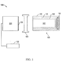
- FIG. 1 illustrates an embodiment of a radiation detection apparatus system 100.
- the radiation detection apparatus system can be a medical imaging apparatus, a well logging apparatus, a security inspection apparatus, nuclear physics applications, or the like.
- the radiation detection apparatus can be used for gamma ray analysis, such as a Single Positron Emission Computer Tomography (SPECT) or Positron Emission Tomography (PET) analysis.
- SPECT Single Positron Emission Computer Tomography
- PET Positron Emission Tomography
- the radiation detection apparatus 100 includes a photosensor 101, an optical interface 103, and a scintillation device 105.
- photosensor 101, the optical interface 103, and the scintillation device 105 are illustrated separate from each other, skilled artisans will appreciate that photosensor 101 and the scintillation device 105 can be coupled to the optical interface 103, with the optical interface 103 disposed between the photosensor 101 and the scintillation device 105.
- the scintillation device 105 and the photosensor 101 can be optically coupled to the optical interface 103 with other known coupling methods, such as the use of an optical gel or bonding agent, or directly through molecular adhesion of optically coupled elements.
- the photosensor 101 may be a photomultiplier tube (PMT), a semiconductor-based photomultiplier, or a hybrid photosensor.
- the photosensor 101 can receive photons emitted by the scintillation device 105, via an input window 116, and produce electrical pulses based on numbers of photons that it receives.
- the photosensor 101 is electrically coupled to an electronics module 130.
- the electrical pulses can be shaped, digitized, analyzed, or any combination thereof by the electronics module 130 to provide a count of the photons received at the photosensor 101 or other information.
- the electronics module 130 can include an amplifier, a pre-amplifier, a discriminator, an analog-to-digital signal converter, a photon counter, another electronic component, or any combination thereof.
- the photosensor 101 can be housed within a tube or housing made of a material capable of protecting the photosensor 101, the electronics module 130, or a combination thereof, such as a metal, metal alloy, other material, or any combination thereof.
- the scintillation device 105 includes a scintillation crystal 107.
- the composition of the scintillation crystal 107 will be described in more detail later in this specification.
- the scintillation crystal 107 is substantially surrounded by a reflector 109.
- the reflector 109 can include polytetrafluoroethylene (PTFE), another material adapted to reflect light emitted by the scintillation crystal 107, or a combination thereof.
- the reflector 109 can be substantially surrounded by a shock absorbing member 111.
- the scintillation crystal 107, the reflector 109, and the shock absorbing member 111 can be housed within a casing 113.
- the scintillation device 105 includes at least one stabilization mechanism adapted to reduce relative movement between the scintillation crystal 107 and other elements of the radiation detection apparatus 100, such as the optical interface 103, the casing 113, the shock absorbing member 111, the reflector 109, or any combination thereof.
- the stabilization mechanism may include a spring 119, an elastomer, another suitable stabilization mechanism, or a combination thereof.
- the stabilization mechanism can be adapted to apply lateral forces, horizontal forces, or a combination thereof, to the scintillation crystal 107 to stabilize its position relative to one or more other elements of the radiation detection apparatus 100.
- the optical interface 103 is adapted to be coupled between the photosensor 101 and the scintillation device 105.
- the optical interface 103 is also adapted to facilitate optical coupling between the photosensor 101 and the scintillation device 105.
- the optical interface 103 can include a polymer, such as a silicone rubber, that is polarized to align the reflective indices of the scintillation crystal 107 and the input window 116.
- the optical interface 103 can include gels or colloids that include polymers and additional elements.
- the scintillation crystal 107 includes a rare earth halide.
- rare earth elements include Y, Sc, and the Lanthanide series elements.
- the scintillation crystal 107 can include one or more other rare earth elements.
- the scintillation crystal 107 has the chemical formula as set forth below. Ln (1-y) RE y X 3 , wherein:
- Ln can include La, Gd, Lu, or any mixture thereof; and RE can include Ce, Eu, Pr, Tb, Nd, or any mixture thereof.
- the scintillation crystal 107 can be La (1-y) Ce y Br 3 .
- LaBr 3 and CeBr 3 are within the scope of compositions described.
- y can be 0 f.u., at least approximately 0.0001 f.u., at least 0.001 f.u., or at least approximately 0.05 f.u.
- y may be 1 f.u., no greater than approximately 0.2 f.u., no greater than approximately 0.1 f.u., no greater than approximately 0.05 f.u, or no greater than approximately 0.01 f.u.
- y is in a range of approximately 0.01 f.u. to approximately 0.1 f.u.
- y is no greater than approximately 0.99 f.u., no greater than approximately 0.9 f.u., or no greater than approximately 0.8 f.u.
- X can include a single halogen or any mixture of halogens.
- X can include Br, I, or any mixture thereof.
- the rare earth halide includes Ca as a co-dopant or a dopant.
- a crystal that includes LaBr 3 co-doped with Ce and Sr has a peak emission that is at a longer wavelength as compared to a crystal that includes LaBr 3 doped with Ce.
- the light output can be more constant than La (1-y) Ce y Br 3 over the range of -40°C to 175° C, and is brighter than La (1-y) Ce y Br 3 at temperatures higher than 50°C.
- La (1-y) Ce y Br 3 doped with Sr may be useful for applications that involve extreme temperature excursions, such as oil well logging and space applications.
- CeBr 3 doped with Sr is brighter than CeBr 3 at temperatures higher than 50°C.
- the light output may be higher than the light output of La (1-y) Ce y Br 3 over the range of room temperature (approximately 22°C) to about 70° C.
- La (1-y) Ce y Br 3 doped with Ba may be useful for outdoor applications, for example for port-of-entry detectors that can be used for vehicles and cargo.
- the co-dopant or dopant can further include at least one Group 1 element and/or at least one Group 2 element.
- Group 1 elements can include Li, Na, Rb, Cs, or any mixture thereon. In a particular embodiment, the Group 1 element is Na.
- Group 2 elements can include Mg, Sr, Ba, or any mixture thereon. In a particular embodiment, the Group 2 element is Sr.
- the content of the co-dopant or dopant is measured as the amount of co-dopant or dopant in a melt used to form the rare earth halide.
- the co-dopant or dopant concentration in the melt can be at least approximately 0.02 wt.%, or in particular at least approximately 0.08 wt.%, at least approximately 0.2 wt.%, or more particularly at least approximately 0.3 wt.%, or even more particularly 0.4 wt.%.
- the co-dopant or dopant concentration in the melt may be no greater than approximately 1.0 wt.%, or in particular no greater than approximately 0.9 wt.%, or more particularly no greater than approximately 0.7 wt.%.
- the co-dopant or dopant concentration in the melt can be in a range approximately 0.2 wt.% to approximately 0.9 wt.% or more particularly, in a range of approximately 0.3 wt.% to 0.7 wt.%.
- the starting materials can include metal halides of the same halogen or different halogens.
- a rare earth bromide and SrBr 2 or NaBr can be used.
- some of the bromide-containing compounds may be replaced with iodide-containing compounds.
- the scintillation crystal can be formed using a conventional technique from a melt. The method can include the Bridgman method, Czochralski crystal growth method, or Kyropolis growth method.
- Scintillation crystals that include a Group 1 element-doped or a Group 2 element-doped rare earth halide having concentrations as previously described provide good scintillating properties, including energy resolution at energies in a range of 10 keV to 2000 keV.
- co-doped or doped rare earth halides can provide unexpected results as compared to other rare earth halide scintillation crystals, particularly at low energies.
- the lower energies can be in a range of approximately 10 keV to approximately 60 keV.
- the Group 2 element-doped scintillation crystals have unusually good proportionality at lower energies, and the Group 1 element-doped and Group 2 element-doped scintillation crystals have good energy resolution over a wide range of energies.
- the range of 10 keV to 356 keV can be further divided into ranges of approximately 10 keV to 30 keV, 30 keV to 60 keV, 60 keV to 356 keV.
- the range of 356 keV to 1332 keV is also examined. While improved performance occurs within each of the ranges, the relative improvement may be more significant for the range of 10 to 60 keV, as compared to the range of 356 keV to 1332 keV or even higher energies. The better performance at lower energies is particularly significant for medical imaging applications.
- the scintillation crystals can be used in other applications, such as well logging in the oil and gas industry as well for the environment monitoring, security applications, and for nuclear physics analysis and applications.
- Energy resolution is the energy range at full-width of half maximum (“FWHM") divided by the energy corresponding to the peak, expressed as a percent. A lower number for energy resolution means that the peak can be resolved more readily. Values for energy resolution may depend on the metrology equipment and the measurement techniques.
- measurements for energy resolution may be performed on scintillation crystals that varied in size from approximately 0.01 cm 3 to approximately 0.2 cm 3 .
- the crystals can be wrapped with a reflector on the sides and one end.
- the crystals may be placed on a window of a PMT and covered with the reflector.
- the reflector may be a specular reflector or a diffuse reflector.
- the reflector may include an aluminum foil, aluminized polyester (e.g. aluminized MylarTM-brand polyester), or a polytetrafluoroethylene (“PTFE”) sheet reflector.
- the scintillation crystal can be placed in a housing where scintillating light passes through a sapphire or quartz window.
- the housed scintillation crystal can be interfaced to a PMT.
- the PMT can be a non-saturated photomultiplier. By non-saturated, the photomultiplier operates in a mode in which significantly more electrons may be generated with a significantly higher rate of photons striking the photocathode of the photomultiplier.
- An exemplary PMT can be a Hamamatsu Model R1791 PMT (available from Hamamatsu Photonics Deutschland GmbH of Herrsching am Ammersee, DE) run at 400 V.
- One or more desired isotopes that emit radiation can be placed one at a time at a predetermined distance, for example, approximately 150 mm (6 inches), from the sample.
- the energy spectra of each isotope and each crystal can be obtained from an ORTEC Model 672 spectroscopic amplifier (available from AMETEK GmbH of Meerbusch, DE) with a 10 ⁇ s shaping time.
- a PMT can be Model 9305 from ET Enterprises Ltd. of Uxbridge, U.K., run at 900 V.
- the energy spectra of each isotope and each crystal can be obtained from a multi-channel analyzer that performs bi-polar shaping at a 0.25 micro-s shaping time.
- An exemplary multichannel analyzer can be obtained from Canberra Industries Inc. of Meriden CT, model Aptec S5008 that has bi-polar shaping, 0.25 micro-s shaping time, and 11-bit digitization.
- the energy resolution values that they obtain may change if the metrology equipment and the measurement techniques are changed.
- the energy resolution values described below can be obtained using the previously described metrology equipment and the measurement conditions to provide a more accurate comparison of energy resolution values between different samples.
- ER Ratio Energy resolution ratio
- ER Ratio Energy resolution ratio
- the ER Ratio is the energy resolution of a particular crystal at a particular energy or range of energies divided by the energy resolution of another crystal at substantially the same energy or range of energies, wherein the energy spectra for the crystals are obtained using the same or substantially identical metrology equipment and techniques.
- LaBr 3 :Ce crystals having a co-dopant may be compared to LaBr 3 :Ce crystals without a co-dopant.
- a doped CeBr 3 crystal can be compared to a substantially undoped CeBr 3 crystal.
- the ER Ratio When comparing a particular scintillation crystal having a composition described herein to a different scintillation crystal having a different composition, a lower ER Ratio allows for more accurate detection of energy peaks.
- the ER Ratio may be no greater than approximately 0.95 for an energy of 8 keV.
- the ER Ratio may be no greater than approximately 0.88, or more particularly, no greater than 0.80 for an energy of 8 keV.
- the ER Ratio may be in a range of approximately 0.79 to approximately 0.95 or more particularly, in a range of approximately 0.79 to approximately 0.86 for an energy of 8 keV.
- the ER Ratio may be no greater than approximately 0.95. In another example, the ER Ratio may be no greater than approximately 0.88, or more particularly, no greater than 0.80 for an energy of 13 keV. In a further example, the ER Ratio may be in a range of approximately 0.78 to approximately 0.95 or more particularly, in a range of approximately 0.79 to approximately 0.88 for an energy of 13 keV.
- the ER Ratio may be no greater than approximately 0.95. In another example, the ER Ratio may be no greater than approximately 0.90, or more particularly, no greater than 0.80 for an energy of 17 keV. In a further example, the ER Ratio may be in a range of approximately 0.76 to approximately 0.95 or more particularly, in a range of approximately 0.78 to approximately 0.90 for an energy of 17 keV. At an energy of 22 keV, the ER Ratio may be no greater than approximately 0.95. In another example, the ER Ratio may be no greater than approximately 0.90, or more particularly, no greater than 0.87 for an energy of 22 keV. In a further example, the ER Ratio may be in a range of approximately 0.84 to approximately 0.95 or more particularly, in a range of approximately 0.85 to approximately 0.90 for an energy of 22 keV.
- the ER Ratio may be no greater than approximately 0.95. In another example, the ER Ratio may be no greater than approximately 0.86, or more particularly, no greater than 0.80 for an energy of 26 keV. In a further example, the ER Ratio may be in a range of approximately 0.75 to approximately 0.95 or more particularly, in a range of approximately 0.77 to approximately 0.90 for an energy of 26 keV. At an energy of 32 keV, the ER Ratio may be no greater than approximately 0.95. In another example, the ER Ratio may be no greater than approximately 0.90, or more particularly, no greater than 0.80 for an energy of 32 keV. In a further example, the ER Ratio may be in a range of approximately 0.75 to approximately 0.95 or more particularly, in a range of approximately 0.76 to approximately 0.90 for an energy of 32 keV.
- the ER Ratio may be no greater than approximately 0.97. In another example, the ER Ratio may be no greater than approximately 0.88, or more particularly, no greater than 0.80 for an energy of 44 keV. In a further example, the ER Ratio may be in a range of approximately 0.70 to approximately 0.97 or more particularly, in a range of approximately 0.73 to approximately 0.85 for an energy of 44 keV. At an energy of 60 keV, the ER Ratio may be no greater than approximately 0.95. In another example, the ER Ratio may be no greater than approximately 0.90, or more particularly, no greater than 0.80 for an energy of 60 keV. In a further example, the ER Ratio may be in a range of approximately 0.70 to approximately 0.95 or more particularly, in a range of approximately 0.76 to approximately 0.91 for an energy of 60 keV.
- the ER Ratio may be no greater than approximately 0.95. In another example, the ER Ratio may be no greater than approximately 0.90, or more particularly, no greater than 0.81 for an energy of 81 keV. In a further example, the ER Ratio may be in a range of approximately 0.75 to approximately 0.95 or more particularly, in a range of approximately 0.79 to approximately 0.90 for an energy of 81 keV. At an energy of 276 keV, the ER Ratio may be no greater than approximately 0.95. In another example, the ER Ratio may be no greater than approximately 0.85, or more particularly, no greater than 0.75 for an energy of 276 keV. In a further example, the ER Ratio may be in a range of approximately 0.70 to approximately 0.95 or more particularly, in a range of approximately 0.73 to approximately 0.85 for an energy of 276 keV.
- the ER Ratio may be no greater than approximately 0.95. In another example, the ER Ratio may be no greater than approximately 0.88, or more particularly, no greater than 0.83 for an energy of 303 keV. In a further example, the ER Ratio may be in a range of approximately 0.80 to approximately 0.95 or more particularly, in a range of approximately 0.81 to approximately 0.90 for an energy of 303 keV. At an energy of 356 keV, the ER Ratio may be no greater than approximately 0.95. In another example, the ER Ratio may be no greater than approximately 0.90, or more particularly, no greater than 0.85 for an energy of 356 keV. In a further example, the ER Ratio may be in a range of approximately 0.80 to approximately 0.95 or more particularly, in a range of approximately 0.81 to approximately 0.86 for an energy of 356 keV.
- the ER Ratio may be no greater than approximately _0.95. In another example, the ER Ratio may be no greater than approximately 0.90, or more particularly, no greater than 0.85 for an energy of 384 keV. In a further example, the ER Ratio may be in a range of approximately 0.80 to approximately 0.95 or more particularly, in a range of approximately 0.81 to approximately 0.88 for an energy of 384 keV. At an energy of 511 keV, the ER Ratio may be no greater than approximately 0.95. In another example, the ER Ratio may be no greater than approximately 0.88, or more particularly, no greater than 0.83 for an energy of 511 keV. In a further example, the ER Ratio may be in a range of approximately 0.78 to approximately 0.95 or more particularly, in a range of approximately 0.80 to approximately 0.80 for an energy of 511 keV.
- the ER Ratio may be no greater than approximately 0.95. In another example, the ER Ratio may be no greater than approximately 0.88, or more particularly, no greater than 0.80 for an energy of 662 keV. In a further example, the ER Ratio may be in a range of approximately 0.74 to approximately 0.95 or more particularly, in a range of approximately 0.76 to approximately 0.85 for an energy of 662 keV. At an energy of 1173 keV, the ER Ratio may be no greater than approximately 0.95. In another example, the ER Ratio may be no greater than approximately 0.90, or more particularly, no greater than 0.80 for an energy of 1173 keV. In a further example, the ER Ratio may be in a range of approximately 0.70 to approximately 0.95 or more particularly, in a range of approximately 0.74 to approximately 0.90 for an energy of 1173 keV.
- the ER Ratio may be no greater than approximately 0.95. In another example, the ER Ratio may be no greater than approximately 0.83, or more particularly, no greater than 0.80 for an energy of 1274 keV. In a further example, the ER Ratio may be in a range of approximately 0.60 to approximately 0.95 or more particularly, in a range of approximately 0.64 to approximately 0.85 for an energy of 1274 keV. At an energy of 1332 keV, the ER Ratio may be no greater than approximately 0.95. In another example, the ER Ratio may be no greater than approximately 0.90, or more particularly, no greater than 0.86 for an energy of 1332 keV. In a further example, the ER Ratio may be in a range of approximately 0.60 to approximately 0.95 or more particularly, in a range of approximately 0.67 to approximately 0.90 for an energy of 1332 keV.
- the improvement in ER Ratio can occur at all energies.
- the improvement in ER Ratio can be more readily seen at higher energies.
- the ER Ratio may become more significant at energies at 60 keV and higher, as compared to energies lower than 60 keV.
- the improvement with ER Ratio with Group 1 elements can be lower than the ER Ratio with a Group 2 element at energies of 356 keV and higher.
- the ER Ratio with a Group 1 element can be lower than 0.70.
- the actual ER Ratios may depend on the concentration of the Group 1 element within the crystal.
- a scintillation crystal formed from a melt that includes 0.5 wt% NaBr can have ER Ratio less than 1, while a a scintillation crystal formed from a melt that includes 2 wt% NaBr can have ER Ratio greater than 1 at the same energies.
- skilled artisans will be able to determine dopants and concentrations to provide an ER Ratio that meets the needs or desires for a particular application.
- Non-proportionality refers to much a scintillation crystal deviates perfect proportionality between gamma ray energy captured and light output. A scintillation crystal having perfect proportionality would always create the same number of photons per unit energy absorbed, regardless of the energy of the gamma ray. Thus, its departure from perfect proportionality is zero.
- nPR Ph z keV , measured / Ph Z keV , 100 ⁇ % nPR ⁇ 100 ⁇ % , wherein Ph Z keV, measured is the number of photoelectrons sensed by the photosensor at an energy of Z keV.
- nPR is the same or improved at energies in a range of 10 keV to 2000 keV when a Group 1 element or a Group 2 element is added as a co-dopant or a dopant in the melt when forming the crystal.
- the value of nPR for rare earth halides when doped with a Group 2 element is more significant at lower energies than it is for higher energies. If the scintillation crystal generates less scintillating light for lower energy gamma rays, the scintillation crystal has poor proportionality.
- the response of the scintillation crystal to gamma rays at lower energies can be more significant to proportionality than the response at higher gamma ray energies, such as greater than 60 keV.
- the improvement in nPR can be even more significant as compared to 30 keV to 60 keV.
- Proportionality can be determined with measuring the scintillation response at many different X-ray or gamma ray energies.
- a particular useful method uses a tunable monochromatic synchrotron X-ray beam, such as provided by the X1 beam line of Hamburger Synhrotronstrahlungslabor at Deutsches Elektronen-Synchrotron, Hamburg, Germany. Details for an experimental setup can be found in " Nonproportional Response of LaBr:Ce and LaCl:Ce Scintillators to Synchrotron X-ray Irradiation," by I. V. Khodyuk and P. Dorenbos, J. Phys. Condens. Matter, vol. 22, p.
- X-ray excited luminescence spectra can be recorded using an X-ray tube with a Cu anode operating at 60 kV and 25 mA.
- the emission of the sample can be focused via a quartz window and a lens on the entrance slit of a monochromator, such as an ARC Model VM-504 monochromator (available from Acton Research Corporation of Acton, MA, US) (blazed at 300nm, 1200 grooves/mm), dispersed and recorded with a photomultiplier tube, such as a Hamamatsu Model R943-02 PMT (available from Hamamatsu Photonics Deutschland GmbH of Herrsching am Ammersee, DE).
- a monochromator such as an ARC Model VM-504 monochromator (available from Acton Research Corporation of Acton, MA, US) (blazed at 300nm, 1200 grooves/mm)
- a photomultiplier tube such as a Hamamatsu Model R943-02 PMT (available from Hamamatsu Photonics Deutschland GmbH of Herrsching am
- the spectra can be corrected for the monochromator transmission and for the quantum efficiency of the PMT.
- X-ray excited luminescence measurements may be performed between 80 and 600K using a cryostat.
- the PMT can be located outside the cryostat and be at room temperature.
- nPR dev The deviation from perfect proportionality (nPR dev ) is nPR minus 100%.
- the parameter nPR dev provides an value to quantify how much nPR is away from 100% and an indicator for direction; minus (-) is below 100%, and plus (+) is above 100%.
- an averaged value a largest positive value, a largest negative value, a maximum value, an absolute value of any of the foregoing, a derivative of any of the foregoing, or any combination thereof can be obtained.
- the averaged value can be an average, a median, or a geometric mean, or may be determined using an integration.
- the average deviation of nPR from 100% can be determined using an integral in accordance with the equation below.
- nPR dev average ⁇ E lower E upper ( nPR E i ⁇ 100 % ⁇ dE i E upper ⁇ E lower
- the absolute value of the deviation is used, and thus, any deviation, whether - or +, is accounted for within the equation.
- a positive deviation is not offset by a negative deviation.
- the measure provides a good indicator of the degree of deviation over a range of energies
- the rare earth halide scintillator crystal can have an nPR dev average of no greater than approximately 8.0%, or more particularly no greater than approximately 5.0%, or even more particularly no greater than approximately 3.0%.
- the rare earth scintillation crystal can have an nPR dev average of no greater than approximately 3.6%, or more particularly no greater than approximately 3.3%, or even more particularly no greater than approximately 2.9%.
- the rare earth halide scintillator crystal can have an nPR dev average of no greater than approximately 2.4%, or more particularly no greater than approximately 1.7%, or even more particularly no greater than approximately 0.7%.
- the rare earth scintillation crystal has an nPR dev average of no greater than approximately 0.5%, or more particularly no greater than approximately 0.20%, or even more particularly no greater than approximately 0.07%.
- CeBr 3 scintillation crystals may have values that depart more strongly from perfect proportionality, as compared to LaBr 3 :Ce scintillation crystal.
- the CeBr 3 scintillation crystal can have an nPR dev average of no greater than approximately 14%, or more particularly no greater than approximately 12%, or even more particularly no greater than approximately 9%.
- the CeBr 3 scintillation crystal can have an nPR dev average of no greater than approximately 8.0%, or more particularly no greater than approximately 6.0%, or even more particularly no greater than approximately 4.0%.
- the CeBr 3 scintillation crystal can have an nPR dev average of no greater than approximately 2.0%, or more particularly no greater than approximately 1.3%, or even more particularly no greater than approximately 0.7%.
- the CeBr 3 scintillation crystal can have nPR dev average of no greater than approximately 0.20%, or more particularly no greater than approximately 0.15%, or even more particularly no greater than approximately 0.09%.
- Scintillator crystals were formed from an open crucible using different combinations of LaBr 3 , CeBr 3 , NaBr, SrBr 2 , and BaBr 2 .
- the values in Table 1 reflect the amounts of the co-dopants and dopants added to the melt.
- the scintillation crystals were analyzed for energy resolution.
- Gamma ray excited pulse-height spectra at room temperature were recorded with a Hamamatsu Model R1791 PMT connected to a Cremat Model CR-112 pre-amplifier and an ORTEC Model 672 spectroscopic amplifier with 10 ⁇ s shaping time.
- the voltage of the PMT was set to 400 V to avoid saturation due to intensive signals in short time interval.
- the bare crystals were mounted on the window of the PMT and covered with several Teflon layers; all pulse-height measurements were performed inside an M-Braun UNILAB dry box with a moisture content less than 1 part per million.
- the yield expressed in photoelectrons per MeV of absorbed gamma ray energy was determined without an optical coupling between the scintillator and the PMT-window.
- the yield was obtained from the ratio between the peak position of the 662-keV photopeak and the position of the mean value of the so-called single photoelectron peak in pulse-height spectra.
- Single photoelectron spectra were recorded with a Hamamatsu Model R1791 PMT connected to a Cremat Model CR-110 pre-amplifier.
- the absolute light yield expressed in photons per MeV was determined by correcting for the quantum efficiency and reflectivity of the PMT.
- the energy resolution is obtained from the data collected using the samples and equipment as previously described.
- Tables 2 and 3 include the energy resolution data for Samples 1 to 10.
- Table 2 - Energy Resolution Data Sample # Description 8 keV 13 keV 17 keV 22 keV 26 keV 32 keV 44 keV 60 keV 81 keV 1 Undoped 40.8 30.9 23.9 20.1 16.7 15.9 14.3 11.3 9.35 La 0.95 Ce 0.05 Br 3 2 Ca-doped 32.3 24.4 18.7 17.2 - 12.1 10.5 8.52 7.38 La 0.95 Ce 0.05 Br 3 3 Sr-doped 34.9 26.5 21.3 18.0 14.9 14.4 12.2 9.08 7.62 La 0.95 Ce 0.05 Br 3 4 Ba-doped 33.4 31.6 19.7 16.9 - 15.3 13.9 10.3 8.70 La 0.95 Ce 0.05 Br 3 5 0.5 % Na-doped 41.7 29.6 23.8 19.8 14.9 15.1 13.9 10.1 8.38 La 0.95 Ce 0.05 Br 3 6 2% Na-
- FIGs. 2 and 3 include plots for the data for Samples 1 to 5.
- FIG. 2 includes energy resolution the data for energies in a range of 8 keV to 81 keV
- FIG. 3 includes the energy resolution data for energies in a range of 276 keV to 662 keV.
- FIGs. 4 and 5 include plots for the data for Samples 7 to 10.
- FIG. 4 includes energy resolution the data for energies in a range of 8 keV to 81 keV
- FIG. 5 includes the energy resolution data for energies in a range of 276 keV to 662 keV.
- the energy resolution ratio (“ER Ratio) is the ratio of the energy resolution of a particular sample divided by the energy resolution of another sample. By using the ER Ratio, the comparison between two different scintillation crystals should have less dependence on the energy, as opposed to using only the energy resolution.
- Tables 4 and 5 include the ER Ratio data. Samples 2 to 6 are compared to Sample 1, and Samples 8 to 10 are compared to Sample 7. For example, the ER Ratio for Sample 2 (in Tables 4 and 5) is the ER for Sample 2 (in Tables 2 and 3) divided by the ER for Sample 1 (in Tables 2 and 3). "N/A" indicates that the ER Ratio is not applicable for the particular sample.
- the data show some variation in ER Ratios for each of the dopants.
- the variation for Samples 2 and 3 (Ca-doped and Sr-doped) have ER Ratios with relatively low standard deviation.
- Sample 2 has an average ER Ratio of 0.81 and a standard deviation of 0.04, and
- Sample 3 has an average ER Ratio of 0.84 and a standard deviation of 0.04.
- Sample 4 (Ba-doped) has a significantly higher ER Ratio average of 0.99 and a standard deviation of 0.11.
- Sample 5 (Na-doped) has an intermediate ER Ratio of 0.86 and a standard deviation 0.11.
- the data suggest that, starting at 60 keV, the ER Ratio for Sample 5 decreases with increasing energy.
- Sample 5 has an ER Ratio less than 0.8, and at 1274 keV, Sample 5 has an ER Ratio less than 0.7. Unlike Sample 5, Samples 2 to 4 do not appear to have any discernible trends regarding ER Ratio as energy increases or decreases.
- Proportionality was studied with a set of set of radioactive sources 60 Co, 22 Na, 137 Cs, 133 Ba, 241 Am, plus Amersham variable energy X-ray source, and at the X-1 beamline at the Hamburger Synchrotronstrahlungslabor (HASYLAB) synchrotron radiation facility in Hamburg, Germany using the experimental setup previously references.
- X-ray excited luminescence spectra were recorded using an X-ray tube with Cu anode operating at 60 kV and 25 mA.
- the emission of the sample was focused via a quartz window and a lens on the entrance slit of an ARC Model VM-504 monochromator (blazed at 300 nm, 1200 grooves/mm), dispersed and recorded with a Hamamatsu Model R943-02 PMT.
- the spectra were corrected for the monochromator transmission and for the quantum efficiency of the PMT.
- X-ray excited luminescence measurements were performed between 80 K and 600 K using a Janis Model VPF-800 Cryostat operated with a LakeShore Model 331 Temperature Controller. The PMT was outside the cryostat and remained at room temperature.
- Tables 6 and 7 include nPR data collected for the scintillation crystals when exposed to gamma ray energies in a range of approximately 8 keV to approximately 1332 keV.
- Table 8 includes nPR data collected for the LaBr 3 :Ce scintillation crystals when exposed to gamma ray energies in a range of approximately 11 keV to approximately 100 keV.
- Table 9 includes nPR data collected for the CeBr 3 scintillation crystals when exposed to gamma ray energies in a range of approximately 13 keV to approximately 100 keV. Data collected at 662 keV was used for determining the nPR data in Table 6 to 9.
- FIGs. 6 and 7 include plots that include the data for Samples 1 to 5, which are the La 0.95 Ce 0.5 Br 3 samples.
- FIG. 6 includes energy resolution the data for energies in a range of 8 keV to 1332 keV.
- the plot shows that the Samples 2 to 4 (Ca-doped, Sr-doped, and Ba-doped) have nPRs values that are much closer to 100% for lower energies, as compared to Sample 1 (undoped).
- Sample 5 Na-doped
- FIG. 7 includes the nPR data for Samples 1 to 3 for energies in a range of 9 keV to 100 keV.
- Sample 1 The difference between Sample 1 and each of Samples 2 and 3 is apparent in FIG. 7 .
- the difference between Sample 1 and each of Samples 2 and 3 is more evident at energies of 32 keV and lower. From the data, Sample 3 appears to have proportionality that is the closest to perfect proportionality over the energy ranges tested, as compared to the other Samples.
- Sample 2 has slightly less uniform proportionality than Sample 3 and has significantly better proportionality as compared to Samples 1 and 5.
- FIGs. 8 and 9 include plots that include the data for Samples 7 to 10, which are the CeBr 3 samples.
- FIG. 8 includes energy resolution the data for energies in a range of 8 keV to 1332 keV.
- the plot shows that the Samples 8 and 9 (Ca-doped and Sr-doped) have nPRs values that are much closer to 100% for lower energies, as compared to Sample 7 (undoped). Samples 8 and 9 have proportionalities that are close to each other over the range of energies tested.
- Sample 10 (Na-doped) does not appear to have any significant improvement for nPR as compared to Sample 7.
- FIG. 9 includes the nPR data for Samples 7 and 9 for energies in a range of 10 keV to 100 keV. The difference between Sample 7 and Sample 9 is apparent in FIG. 9 . The difference between Sample 7 and Sample 9 is more evident at energies of 32 keV and lower.
- nPR dev nPR ⁇ 100 ⁇ % .
- Tables 10 to 13 include the nPR dev data that is derived from the nPR data in Tables 6 to 9.
- FIGs. 8 and 9 include plots for the data for Samples 7 to 10, which are the CeBr 3 samples.
- FIG. 8 includes energy resolution the data for energies in a range of 8 keV to 1332 keV.
- the plot shows that the Samples 8 and 9 (Ca-doped and Sr-doped) have nPRs values that are much closer to 100% for lower energies, as compared to Sample 7 (undoped).
- Samples 8 and 9 have proportionalities that are close to each other over the range of energies tested.
- Sample 10 (Na-doped) does not appear to have any significant improvement for nPR, as compared to Sample 7.
- FIG. 9 includes the nPR data for Samples 7 and 9 for energies in a range of 10 keV to 100 keV. The difference between Sample 7 and Sample 9 is apparent in FIG. 9 . The difference between Sample 7 and Sample 9 is more evident at energies of 32 keV and lower.
- Data for nPR dev can be used to determine an nPR dev average for a particular range of energies.
- Table 14 includes nPR dev average values determined as previously described.
- Table 14 - nPR dev average Data Sample # Description 11 or 13 keV to 30 keV 30 keV to 60 keV 60 keV to 356 keV 356 keV to 1332 keV 1 Undoped 8.9 3.7 0.26 0.15 La 0.95 Ce 0.05 Br 3 2 Ca-doped 2.6 3.6 1.3 0.23 La 0.95 Ce 0.05 Br 3 3 Sr-doped 1.3 2.5 1.2 0.13 La 0.95 Ce 0.05 Br 3 4 Ba-doped - - 0.90 0.17 La 0.95 Ce 0.05 Br 3 5 0.5% Na-doped - - 0.63 0.22 La 0.95 Ce 0.05 Br 3 7 Undoped CeBr 3 15.8 7.7 2.5 0.08 8 Ca-doped CeBr 3 - - 0.63 015 9 Sr-doped CeB
- nPR dev average Data for nPR dev average is good for distinguishing which samples are more proportional over one or more ranges of energies.
- Sample 3 (Sr-doped) has the best performance over all the energies, particularly at energies from 11 keV to 60 keV.
- Sample 2 has good proportionality at 11 to 30 keV.
- Sample 2 At energies in a range of 30 to 60 keV, Sample 2 has nearly the same magnitude of deviation from proportionality as compared to Sample 1.
- the deviation for Samples 1 and 2 are in opposite directions (- for Sample 1 and + for Sample 2).
- Samples 2 to 4 For energies in a range of 60 keV to 356 keV, Samples 2 to 4 have positive deviation from 100%, and Sample 1 has deviation from 100% that is closer to zero.
- the Samples 1 to 5 For energies in a range of 356 keV to 1332 keV, the Samples 1 to 5 have nPR dev average values that are less than 0.1% different from one another.
- Sample 9 has the best performance over all the energies, particularly at energies from 11 keV to 60 keV.
- Sample 8 (Ca-doped) does not have as much data, the relationship between Samples 8 and 9 for nPR dev average is expected to be about the same as the relationship between Samples 2 and 3 for nPR dev average.
- Samples 8 and 9 For energies in a range of 60 keV to 356 keV, Samples 8 and 9 have better proportionality compared to Sample 7 (undoped).
- the Samples 7 to 9 have nPR dev average values that are less than 0.1% different from one another.
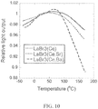
- the samples include LaBr 3 (Ce), LaBr 3 (Ce,Sr) and LaBr 3 (Ce,Ba).
- the cerium concentration in each sample was 4.5 to 5%, meaning that 4.5 to 5% of the La atoms were replaced by Ce.
- the Sr concentration was 180 parts per million by weight, and the Ba concentration was 160 parts per million by weight.
- Each crystal was formed as a right circular cylinder with dimensions where the diameter was approximately 2.5 cm and length was approximately 2.5 cm.
- the light output was measured by locating the centroid of the 662 keV photopeak from a 10 micro-Ci 137 Cs gamma ray source. The source was placed at a distance of 10 mm from one end of the crystal. The other end was coupled to a photomultiplier tube (model: Photonis 20Y0) that was kept at a constant 30° C.
- FIG. 10 includes a plot showing the temperature response of standard, LaBr 3 (Ce), LaBr 3 (Ce,Sr) and LaBr 3 (Ce,Ba). Specifically, the graph shows how the scintillation light output changes with temperature from -40°C to 175° C. Each curve is normalized to 1.0 at 25° C. When co-doped with Sr, the light output is more constant than standard over the range of -40°C to 175° C, and is measurably brighter than standard at the highest temperatures. This makes Sr co-doped lanthanum bromide desirable for applications that involve extreme temperature excursions, such as oil well logging and space applications.
- the light output increases over the range of room temperature (approximately 22°C) to about 70° C. This makes Ba co-doped lanthanum bromide desirable for outdoor applications, for example for port-of-entry detectors that can be used for vehicles and cargo.
Description
- The present disclosure is directed to scintillation crystals including rare earth halides and radiation detection apparatuses including such scintillation crystals.
- Radiation detection apparatuses are used in a variety of applications. For example, scintillators can be used for medical imaging and for well logging in the oil and gas industry as well for the environment monitoring, security applications, and for nuclear physics analysis and applications. Scintillation crystals used for radiation detection apparatuses can include rare earth halides. Further improvement of scintillation crystals is desired.
-
US 2008/067391 A1 discloses a scintillator crystal represented by the general formula Ln(1-y)CeyX3:M, wherein Ln(1-y)CeyX3 represents the chemical composition of the matrix material, Ln represents one or more elements selected from the group consisting of rare earth elements, X represents one or more elements selected from the group consisting of halogen elements, M is the constituent element of the dopant which is doped in the matrix material and represents one or more elements selected from the group consisting of Li, Na, K, Rb, Cs, Al, Zn, Ga, Be, Mg, Ca, Sr, Ba, Sc, Ge, Ti, V, Cu, Nb, Cr, Mn, Fe, Co, Ni, Mo, Ru, Rh, Pb, Ag, Cd, In, Sn, Sb, Ta, W, Re, Os, Ir, Pt, Au, Hg, Tl and Bi. The index y represents a numerical value within the range 0.0001 ≤ y ≤ 1. - Subject matter of the present invention is a scintillation crystal as defined in claim 1, and a radiation detection apparatus as defined in
claim 2 comprising the scintillation crystal. The dependent claims relate to particular embodiments thereof. - Embodiments are illustrated by way of example and are not limited in the accompanying figures.
-
FIG. 1 includes an illustration of a radiation detection apparatus in accordance with an embodiment. -
FIG. 2 includes a plot of energy resolution as a function of energy for different compositions of LaBr3:Ce scintillation crystals at gamma ray energies in a range of approximately 8 keV to approximately 90 keV. -
FIG. 3 includes a plot of energy resolution ratio as a function of energy for different compositions of LaBr3:Ce scintillation crystals at gamma ray energies in a range of approximately 276 keV to approximately 662 keV. -
FIG. 4 includes a plot of energy resolution as a function of energy for different compositions of CeBr3 scintillation crystals at gamma ray energies in a range of approximately 8 keV to approximately 90 keV. -
FIG. 5 includes a plot of energy resolution ratio as a function of energy for different compositions of CeBr3 scintillation crystals at gamma ray energies in a range of approximately 276 keV to approximately 662 keV. -
FIG. 6 includes a plot of non-proportionality for different compositions of LaBr3:Ce scintillation crystals at gamma ray energies in a range of approximately 8 keV to approximately 1332 keV. -
FIG. 7 includes a plot of non-proportionality for different compositions of LaBr3:Ce scintillation crystals at gamma ray energies in a range of approximately 9 keV to approximately 100 keV. -
FIG. 8 includes a plot of non-proportionality for different compositions of CeBr3 scintillation crystals at gamma ray energies in a range of approximately 8 keV to approximately 1332 keV. -
FIG. 9 includes a plot of non-proportionality for different compositions of CeBr3 scintillation crystals at gamma ray energies in a range of approximately 11 keV to approximately 100 keV. -
FIG. 10 includes a plot of relative light output for different compositions of LaBr3 scintillation crystals over a range of temperatures. - Skilled artisans appreciate that elements in the figures are illustrated for simplicity and clarity and have not necessarily been drawn to scale. For example, the dimensions of some of the elements in the figures may be exaggerated relative to other elements to help to improve understanding of embodiments of the invention.
- The following description in combination with the figures is provided to assist in understanding the teachings disclosed herein. The following discussion will focus on specific implementations and embodiments of the teachings. This focus is provided to assist in describing the teachings and should not be interpreted as a limitation on the scope or applicability of the teachings.
- The term "averaged," when referring to a value, is intended to mean an average, a geometric mean, or a median value.
- As used herein, the terms "comprises," "comprising," "includes, " "including, " "has, " "having," or any other variation thereof, are intended to cover a non-exclusive inclusion. For example, a process, method, article, or apparatus that comprises a list of features is not necessarily limited only to those features but may include other features not expressly listed or inherent to such process, method, article, or apparatus. Further, unless expressly stated to the contrary, "or" refers to an inclusive-or and not to an exclusive-or. For example, a condition A or B is satisfied by any one of the following: A is true (or present) and B is false (or not present), A is false (or not present) and B is true (or present), and both A and B are true (or present).
- The use of "a" or "an" is employed to describe elements and components described herein. This is done merely for convenience and to give a general sense of the scope of the invention. This description should be read to include one or at least one and the singular also includes the plural, or vice versa, unless it is clear that it is meant otherwise.
- Unless otherwise defined, all technical and scientific terms used herein have the same meaning as commonly understood by one of ordinary skill in the art to which this invention belongs. The materials, methods, and examples are illustrative only and not intended to be limiting. To the extent not described herein, many details regarding specific materials and processing acts are conventional and may be found in textbooks and other sources within the scintillation and radiation detection arts.
-
FIG. 1 illustrates an embodiment of a radiationdetection apparatus system 100. The radiation detection apparatus system can be a medical imaging apparatus, a well logging apparatus, a security inspection apparatus, nuclear physics applications, or the like. In a particular embodiment, the radiation detection apparatus can be used for gamma ray analysis, such as a Single Positron Emission Computer Tomography (SPECT) or Positron Emission Tomography (PET) analysis. - In the embodiment illustrated, the
radiation detection apparatus 100 includes aphotosensor 101, anoptical interface 103, and ascintillation device 105. Although thephotosensor 101, theoptical interface 103, and thescintillation device 105 are illustrated separate from each other, skilled artisans will appreciate thatphotosensor 101 and thescintillation device 105 can be coupled to theoptical interface 103, with theoptical interface 103 disposed between thephotosensor 101 and thescintillation device 105. Thescintillation device 105 and thephotosensor 101 can be optically coupled to theoptical interface 103 with other known coupling methods, such as the use of an optical gel or bonding agent, or directly through molecular adhesion of optically coupled elements. - The
photosensor 101 may be a photomultiplier tube (PMT), a semiconductor-based photomultiplier, or a hybrid photosensor. Thephotosensor 101 can receive photons emitted by thescintillation device 105, via aninput window 116, and produce electrical pulses based on numbers of photons that it receives. Thephotosensor 101 is electrically coupled to anelectronics module 130. The electrical pulses can be shaped, digitized, analyzed, or any combination thereof by theelectronics module 130 to provide a count of the photons received at thephotosensor 101 or other information. Theelectronics module 130 can include an amplifier, a pre-amplifier, a discriminator, an analog-to-digital signal converter, a photon counter, another electronic component, or any combination thereof. Thephotosensor 101 can be housed within a tube or housing made of a material capable of protecting thephotosensor 101, theelectronics module 130, or a combination thereof, such as a metal, metal alloy, other material, or any combination thereof. - The
scintillation device 105 includes ascintillation crystal 107. The composition of thescintillation crystal 107 will be described in more detail later in this specification. Thescintillation crystal 107 is substantially surrounded by areflector 109. In one embodiment, thereflector 109 can include polytetrafluoroethylene (PTFE), another material adapted to reflect light emitted by thescintillation crystal 107, or a combination thereof. In an illustrative embodiment, thereflector 109 can be substantially surrounded by ashock absorbing member 111. Thescintillation crystal 107, thereflector 109, and theshock absorbing member 111 can be housed within acasing 113. - The
scintillation device 105 includes at least one stabilization mechanism adapted to reduce relative movement between thescintillation crystal 107 and other elements of theradiation detection apparatus 100, such as theoptical interface 103, thecasing 113, theshock absorbing member 111, thereflector 109, or any combination thereof. The stabilization mechanism may include aspring 119, an elastomer, another suitable stabilization mechanism, or a combination thereof. The stabilization mechanism can be adapted to apply lateral forces, horizontal forces, or a combination thereof, to thescintillation crystal 107 to stabilize its position relative to one or more other elements of theradiation detection apparatus 100. - As illustrated, the
optical interface 103 is adapted to be coupled between thephotosensor 101 and thescintillation device 105. Theoptical interface 103 is also adapted to facilitate optical coupling between thephotosensor 101 and thescintillation device 105. Theoptical interface 103 can include a polymer, such as a silicone rubber, that is polarized to align the reflective indices of thescintillation crystal 107 and theinput window 116. In other embodiments, theoptical interface 103 can include gels or colloids that include polymers and additional elements. - The
scintillation crystal 107 includes a rare earth halide. As used herein, rare earth elements include Y, Sc, and the Lanthanide series elements. In an embodiment, thescintillation crystal 107 can include one or more other rare earth elements. Thus, thescintillation crystal 107 has the chemical formula as set forth below.
Ln(1-y)REyX3,
wherein: - Ln represents a rare earth element;
- RE represents a different rare earth element;
- y has a value in a range of 0 to 1 formula unit ("f.u."); and
- X represents a halogen.
- In particular embodiment, Ln can include La, Gd, Lu, or any mixture thereof; and RE can include Ce, Eu, Pr, Tb, Nd, or any mixture thereof. In a particular embodiment, the
scintillation crystal 107 can be La(1-y)CeyBr3. In particular embodiments, LaBr3 and CeBr3 are within the scope of compositions described. - In another embodiment y can be 0 f.u., at least approximately 0.0001 f.u., at least 0.001 f.u., or at least approximately 0.05 f.u. In a further embodiment, y may be 1 f.u., no greater than approximately 0.2 f.u., no greater than approximately 0.1 f.u., no greater than approximately 0.05 f.u, or no greater than approximately 0.01 f.u. In a particular embodiment, y is in a range of approximately 0.01 f.u. to approximately 0.1 f.u. In a further embodiment, y is no greater than approximately 0.99 f.u., no greater than approximately 0.9 f.u., or no greater than approximately 0.8 f.u. X can include a single halogen or any mixture of halogens. For example, X can include Br, I, or any mixture thereof.
- The rare earth halide includes Ca as a co-dopant or a dopant. A crystal that includes LaBr3 co-doped with Ce and Sr has a peak emission that is at a longer wavelength as compared to a crystal that includes LaBr3 doped with Ce. Further, when La(1-y)CeyBr3 is doped with Sr, the light output can be more constant than La(1-y)CeyBr3 over the range of -40°C to 175° C, and is brighter than La(1-y)CeyBr3 at temperatures higher than 50°C. Thus, La(1-y)CeyBr3 doped with Sr may be useful for applications that involve extreme temperature excursions, such as oil well logging and space applications. Similar to La(1-y)CeyBr3, CeBr3 doped with Sr is brighter than CeBr3 at temperatures higher than 50°C. When La(1-y)CeyBr3 is doped with Ba, the light output may be higher than the light output of La(1-y)CeyBr3 over the range of room temperature (approximately 22°C) to about 70° C. La(1-y)CeyBr3 doped with Ba may be useful for outdoor applications, for example for port-of-entry detectors that can be used for vehicles and cargo.
- In a further embodiment, the co-dopant or dopant can further include at least one Group 1 element and/or at least one
Group 2 element. Group 1 elements can include Li, Na, Rb, Cs, or any mixture thereon. In a particular embodiment, the Group 1 element is Na.Group 2 elements can include Mg, Sr, Ba, or any mixture thereon. In a particular embodiment, theGroup 2 element is Sr. The content of the co-dopant or dopant is measured as the amount of co-dopant or dopant in a melt used to form the rare earth halide. The co-dopant or dopant concentration in the melt can be at least approximately 0.02 wt.%, or in particular at least approximately 0.08 wt.%, at least approximately 0.2 wt.%, or more particularly at least approximately 0.3 wt.%, or even more particularly 0.4 wt.%. In another embodiment, the co-dopant or dopant concentration in the melt may be no greater than approximately 1.0 wt.%, or in particular no greater than approximately 0.9 wt.%, or more particularly no greater than approximately 0.7 wt.%. In a particular embodiment, the co-dopant or dopant concentration in the melt can be in a range approximately 0.2 wt.% to approximately 0.9 wt.% or more particularly, in a range of approximately 0.3 wt.% to 0.7 wt.%. - The starting materials can include metal halides of the same halogen or different halogens. For example, a rare earth bromide and SrBr2 or NaBr can be used. In another embodiment, some of the bromide-containing compounds may be replaced with iodide-containing compounds. The scintillation crystal can be formed using a conventional technique from a melt. The method can include the Bridgman method, Czochralski crystal growth method, or Kyropolis growth method.
- Scintillation crystals that include a Group 1 element-doped or a
Group 2 element-doped rare earth halide having concentrations as previously described provide good scintillating properties, including energy resolution at energies in a range of 10 keV to 2000 keV. In another example, co-doped or doped rare earth halides can provide unexpected results as compared to other rare earth halide scintillation crystals, particularly at low energies. In a particular example, the lower energies can be in a range of approximately 10 keV to approximately 60 keV. More particularly, theGroup 2 element-doped scintillation crystals have unusually good proportionality at lower energies, and the Group 1 element-doped andGroup 2 element-doped scintillation crystals have good energy resolution over a wide range of energies. The range of 10 keV to 356 keV can be further divided into ranges of approximately 10 keV to 30 keV, 30 keV to 60 keV, 60 keV to 356 keV. The range of 356 keV to 1332 keV is also examined. While improved performance occurs within each of the ranges, the relative improvement may be more significant for the range of 10 to 60 keV, as compared to the range of 356 keV to 1332 keV or even higher energies. The better performance at lower energies is particularly significant for medical imaging applications. The scintillation crystals can be used in other applications, such as well logging in the oil and gas industry as well for the environment monitoring, security applications, and for nuclear physics analysis and applications. - Energy resolution is the energy range at full-width of half maximum ("FWHM") divided by the energy corresponding to the peak, expressed as a percent. A lower number for energy resolution means that the peak can be resolved more readily. Values for energy resolution may depend on the metrology equipment and the measurement techniques.
- In an example, measurements for energy resolution may be performed on scintillation crystals that varied in size from approximately 0.01 cm3 to approximately 0.2 cm3. The crystals can be wrapped with a reflector on the sides and one end. Alternatively, the crystals may be placed on a window of a PMT and covered with the reflector. In a particular example, the reflector may be a specular reflector or a diffuse reflector. For example, the reflector may include an aluminum foil, aluminized polyester (e.g. aluminized Mylar™-brand polyester), or a polytetrafluoroethylene ("PTFE") sheet reflector. The scintillation crystal can be placed in a housing where scintillating light passes through a sapphire or quartz window.
- The housed scintillation crystal can be interfaced to a PMT. In an example, the PMT can be a non-saturated photomultiplier. By non-saturated, the photomultiplier operates in a mode in which significantly more electrons may be generated with a significantly higher rate of photons striking the photocathode of the photomultiplier. An exemplary PMT can be a Hamamatsu Model R1791 PMT (available from Hamamatsu Photonics Deutschland GmbH of Herrsching am Ammersee, DE) run at 400 V. One or more desired isotopes that emit radiation can be placed one at a time at a predetermined distance, for example, approximately 150 mm (6 inches), from the sample. The energy spectra of each isotope and each crystal can be obtained from an ORTEC Model 672 spectroscopic amplifier (available from AMETEK GmbH of Meerbusch, DE) with a 10 µs shaping time.
- In another example, different equipment may be used. For example, a PMT can be Model 9305 from ET Enterprises Ltd. of Uxbridge, U.K., run at 900 V. The energy spectra of each isotope and each crystal can be obtained from a multi-channel analyzer that performs bi-polar shaping at a 0.25 micro-s shaping time. An exemplary multichannel analyzer can be obtained from Canberra Industries Inc. of Meriden CT, model Aptec S5008 that has bi-polar shaping, 0.25 micro-s shaping time, and 11-bit digitization. After reading this specification, skilled artisans will be able to select metrology equipment for their particular applications.
- After reading this specification, skilled artisans will appreciate that the energy resolution values that they obtain may change if the metrology equipment and the measurement techniques are changed. The energy resolution values described below can be obtained using the previously described metrology equipment and the measurement conditions to provide a more accurate comparison of energy resolution values between different samples.
- Energy resolution ratio ("ER Ratio") may be used to compare the energy resolutions of different compositions of materials for a particular energy or range of energies. ER Ratio can allow for a better comparison as opposed to energy resolution because ER Ratios can be obtained using substantially the same metrology equipment and techniques. Thus, variations based on metrology equipment and techniques can be substantially eliminated.
- In an example, the ER Ratio is the energy resolution of a particular crystal at a particular energy or range of energies divided by the energy resolution of another crystal at substantially the same energy or range of energies, wherein the energy spectra for the crystals are obtained using the same or substantially identical metrology equipment and techniques. In an example, LaBr3:Ce crystals having a co-dopant may be compared to LaBr3:Ce crystals without a co-dopant. In another example, a doped CeBr3 crystal can be compared to a substantially undoped CeBr3 crystal.
- When comparing a particular scintillation crystal having a composition described herein to a different scintillation crystal having a different composition, a lower ER Ratio allows for more accurate detection of energy peaks. When comparing the scintillation crystals for particular energies, the ER Ratio may be no greater than approximately 0.95 for an energy of 8 keV. In another example, the ER Ratio may be no greater than approximately 0.88, or more particularly, no greater than 0.80 for an energy of 8 keV. In a further example, the ER Ratio may be in a range of approximately 0.79 to approximately 0.95 or more particularly, in a range of approximately 0.79 to approximately 0.86 for an energy of 8 keV. At an energy of 13 keV, the ER Ratio may be no greater than approximately 0.95. In another example, the ER Ratio may be no greater than approximately 0.88, or more particularly, no greater than 0.80 for an energy of 13 keV. In a further example, the ER Ratio may be in a range of approximately 0.78 to approximately 0.95 or more particularly, in a range of approximately 0.79 to approximately 0.88 for an energy of 13 keV.
- At an energy of 17 keV, the ER Ratio may be no greater than approximately 0.95. In another example, the ER Ratio may be no greater than approximately 0.90, or more particularly, no greater than 0.80 for an energy of 17 keV. In a further example, the ER Ratio may be in a range of approximately 0.76 to approximately 0.95 or more particularly, in a range of approximately 0.78 to approximately 0.90 for an energy of 17 keV. At an energy of 22 keV, the ER Ratio may be no greater than approximately 0.95. In another example, the ER Ratio may be no greater than approximately 0.90, or more particularly, no greater than 0.87 for an energy of 22 keV. In a further example, the ER Ratio may be in a range of approximately 0.84 to approximately 0.95 or more particularly, in a range of approximately 0.85 to approximately 0.90 for an energy of 22 keV.
- At an energy of 26 keV, the ER Ratio may be no greater than approximately 0.95. In another example, the ER Ratio may be no greater than approximately 0.86, or more particularly, no greater than 0.80 for an energy of 26 keV. In a further example, the ER Ratio may be in a range of approximately 0.75 to approximately 0.95 or more particularly, in a range of approximately 0.77 to approximately 0.90 for an energy of 26 keV. At an energy of 32 keV, the ER Ratio may be no greater than approximately 0.95. In another example, the ER Ratio may be no greater than approximately 0.90, or more particularly, no greater than 0.80 for an energy of 32 keV. In a further example, the ER Ratio may be in a range of approximately 0.75 to approximately 0.95 or more particularly, in a range of approximately 0.76 to approximately 0.90 for an energy of 32 keV.
- At an energy of 44 keV, the ER Ratio may be no greater than approximately 0.97. In another example, the ER Ratio may be no greater than approximately 0.88, or more particularly, no greater than 0.80 for an energy of 44 keV. In a further example, the ER Ratio may be in a range of approximately 0.70 to approximately 0.97 or more particularly, in a range of approximately 0.73 to approximately 0.85 for an energy of 44 keV. At an energy of 60 keV, the ER Ratio may be no greater than approximately 0.95. In another example, the ER Ratio may be no greater than approximately 0.90, or more particularly, no greater than 0.80 for an energy of 60 keV. In a further example, the ER Ratio may be in a range of approximately 0.70 to approximately 0.95 or more particularly, in a range of approximately 0.76 to approximately 0.91 for an energy of 60 keV.
- At an energy of 81 keV, the ER Ratio may be no greater than approximately 0.95. In another example, the ER Ratio may be no greater than approximately 0.90, or more particularly, no greater than 0.81 for an energy of 81 keV. In a further example, the ER Ratio may be in a range of approximately 0.75 to approximately 0.95 or more particularly, in a range of approximately 0.79 to approximately 0.90 for an energy of 81 keV. At an energy of 276 keV, the ER Ratio may be no greater than approximately 0.95. In another example, the ER Ratio may be no greater than approximately 0.85, or more particularly, no greater than 0.75 for an energy of 276 keV. In a further example, the ER Ratio may be in a range of approximately 0.70 to approximately 0.95 or more particularly, in a range of approximately 0.73 to approximately 0.85 for an energy of 276 keV.
- At an energy of 303 keV, the ER Ratio may be no greater than approximately 0.95. In another example, the ER Ratio may be no greater than approximately 0.88, or more particularly, no greater than 0.83 for an energy of 303 keV. In a further example, the ER Ratio may be in a range of approximately 0.80 to approximately 0.95 or more particularly, in a range of approximately 0.81 to approximately 0.90 for an energy of 303 keV. At an energy of 356 keV, the ER Ratio may be no greater than approximately 0.95. In another example, the ER Ratio may be no greater than approximately 0.90, or more particularly, no greater than 0.85 for an energy of 356 keV. In a further example, the ER Ratio may be in a range of approximately 0.80 to approximately 0.95 or more particularly, in a range of approximately 0.81 to approximately 0.86 for an energy of 356 keV.
- At an energy of 384 keV, the ER Ratio may be no greater than approximately _0.95. In another example, the ER Ratio may be no greater than approximately 0.90, or more particularly, no greater than 0.85 for an energy of 384 keV. In a further example, the ER Ratio may be in a range of approximately 0.80 to approximately 0.95 or more particularly, in a range of approximately 0.81 to approximately 0.88 for an energy of 384 keV. At an energy of 511 keV, the ER Ratio may be no greater than approximately 0.95. In another example, the ER Ratio may be no greater than approximately 0.88, or more particularly, no greater than 0.83 for an energy of 511 keV. In a further example, the ER Ratio may be in a range of approximately 0.78 to approximately 0.95 or more particularly, in a range of approximately 0.80 to approximately 0.80 for an energy of 511 keV.
- At an energy of 662 keV, the ER Ratio may be no greater than approximately 0.95. In another example, the ER Ratio may be no greater than approximately 0.88, or more particularly, no greater than 0.80 for an energy of 662 keV. In a further example, the ER Ratio may be in a range of approximately 0.74 to approximately 0.95 or more particularly, in a range of approximately 0.76 to approximately 0.85 for an energy of 662 keV. At an energy of 1173 keV, the ER Ratio may be no greater than approximately 0.95. In another example, the ER Ratio may be no greater than approximately 0.90, or more particularly, no greater than 0.80 for an energy of 1173 keV. In a further example, the ER Ratio may be in a range of approximately 0.70 to approximately 0.95 or more particularly, in a range of approximately 0.74 to approximately 0.90 for an energy of 1173 keV.
- At an energy of 1274 keV, the ER Ratio may be no greater than approximately 0.95. In another example, the ER Ratio may be no greater than approximately 0.83, or more particularly, no greater than 0.80 for an energy of 1274 keV. In a further example, the ER Ratio may be in a range of approximately 0.60 to approximately 0.95 or more particularly, in a range of approximately 0.64 to approximately 0.85 for an energy of 1274 keV. At an energy of 1332 keV, the ER Ratio may be no greater than approximately 0.95. In another example, the ER Ratio may be no greater than approximately 0.90, or more particularly, no greater than 0.86 for an energy of 1332 keV. In a further example, the ER Ratio may be in a range of approximately 0.60 to approximately 0.95 or more particularly, in a range of approximately 0.67 to approximately 0.90 for an energy of 1332 keV.
- For a
Group 2 element, the improvement in ER Ratio can occur at all energies. For a Group 1 clement, the improvement in ER Ratio, can be more readily seen at higher energies. In particular, for a scintillator crystal doped with a Group 1 element, the ER Ratio may become more significant at energies at 60 keV and higher, as compared to energies lower than 60 keV. Further, the improvement with ER Ratio with Group 1 elements can be lower than the ER Ratio with aGroup 2 element at energies of 356 keV and higher. In particular, the ER Ratio with a Group 1 element can be lower than 0.70. The actual ER Ratios may depend on the concentration of the Group 1 element within the crystal. For example, at energies between 44 keV and 60 keV, a scintillation crystal formed from a melt that includes 0.5 wt% NaBr can have ER Ratio less than 1, while a a scintillation crystal formed from a melt that includes 2 wt% NaBr can have ER Ratio greater than 1 at the same energies. After reading this specification, skilled artisans will be able to determine dopants and concentrations to provide an ER Ratio that meets the needs or desires for a particular application. - Non-proportionality (nPR) refers to much a scintillation crystal deviates perfect proportionality between gamma ray energy captured and light output. A scintillation crystal having perfect proportionality would always create the same number of photons per unit energy absorbed, regardless of the energy of the gamma ray. Thus, its departure from perfect proportionality is zero. For the purposes of this specification, nPR for each scintillation crystal is normalized at 662 keV. When nPR is 100%, the photoelectrons at a particular energy, referred to as Z keV will be:

- wherein PhzkeV, 100% nPR is the number of photoelectrons predicted to be sensed by a photosensor at an energy of Z keV when nPR is 100%, and
- Ph662 keV is the number of photoelectrons sensed by the photosensor at 662 keV.
- Thus, nPR is:

- The value of nPR is the same or improved at energies in a range of 10 keV to 2000 keV when a Group 1 element or a
Group 2 element is added as a co-dopant or a dopant in the melt when forming the crystal. The value of nPR for rare earth halides when doped with aGroup 2 element is more significant at lower energies than it is for higher energies. If the scintillation crystal generates less scintillating light for lower energy gamma rays, the scintillation crystal has poor proportionality. Thus, the response of the scintillation crystal to gamma rays at lower energies, such no greater than 60 keV, can be more significant to proportionality than the response at higher gamma ray energies, such as greater than 60 keV. At energies lower than 30 keV, the improvement in nPR can be even more significant as compared to 30 keV to 60 keV. - Proportionality can be determined with measuring the scintillation response at many different X-ray or gamma ray energies. A particular useful method uses a tunable monochromatic synchrotron X-ray beam, such as provided by the X1 beam line of Hamburger Synhrotronstrahlungslabor at Deutsches Elektronen-Synchrotron, Hamburg, Germany. Details for an experimental setup can be found in "Nonproportional Response of LaBr:Ce and LaCl:Ce Scintillators to Synchrotron X-ray Irradiation," by I. V. Khodyuk and P. Dorenbos, J. Phys. Condens. Matter, vol. 22, p. 485402, 2010, which is incorporated herein for its detail regarding the experimental setup. X-ray excited luminescence spectra can be recorded using an X-ray tube with a Cu anode operating at 60 kV and 25 mA. The emission of the sample can be focused via a quartz window and a lens on the entrance slit of a monochromator, such as an ARC Model VM-504 monochromator (available from Acton Research Corporation of Acton, MA, US) (blazed at 300nm, 1200 grooves/mm), dispersed and recorded with a photomultiplier tube, such as a Hamamatsu Model R943-02 PMT (available from Hamamatsu Photonics Deutschland GmbH of Herrsching am Ammersee, DE). The spectra can be corrected for the monochromator transmission and for the quantum efficiency of the PMT. X-ray excited luminescence measurements may be performed between 80 and 600K using a cryostat. The PMT can be located outside the cryostat and be at room temperature.
- The deviation from perfect proportionality (nPR dev) is nPR minus 100%. The parameter nPR dev provides an value to quantify how much nPR is away from 100% and an indicator for direction; minus (-) is below 100%, and plus (+) is above 100%. For a set of nPR data points, an averaged value, a largest positive value, a largest negative value, a maximum value, an absolute value of any of the foregoing, a derivative of any of the foregoing, or any combination thereof can be obtained. The averaged value can be an average, a median, or a geometric mean, or may be determined using an integration. In a particular example, the average deviation of nPR from 100% can be determined using an integral in accordance with the equation below.

- nPR(Ei) is nPR at energy Ei;
- Eupper is the upper limit of the energy range; and
- Elower is the lower limit of the energy range.
- In the equation above, the absolute value of the deviation is used, and thus, any deviation, whether - or +, is accounted for within the equation. In particular, a positive deviation is not offset by a negative deviation. Thus, the measure provides a good indicator of the degree of deviation over a range of energies
- For a radiation energy range from 11 keV to 30 keV, the rare earth halide scintillator crystal can have an nPRdev average of no greater than approximately 8.0%, or more particularly no greater than approximately 5.0%, or even more particularly no greater than approximately 3.0%. For the radiation energy range of 30 keV to 60 keV, the rare earth scintillation crystal can have an nPRdev average of no greater than approximately 3.6%, or more particularly no greater than approximately 3.3%, or even more particularly no greater than approximately 2.9%.
- For a radiation energy range from 60 keV to 356 keV, the rare earth halide scintillator crystal can have an nPRdev average of no greater than approximately 2.4%, or more particularly no greater than approximately 1.7%, or even more particularly no greater than approximately 0.7%. For the radiation energy range of 356 keV to 1332 keV, the rare earth scintillation crystal has an nPRdev average of no greater than approximately 0.5%, or more particularly no greater than approximately 0.20%, or even more particularly no greater than approximately 0.07%.
- CeBr3 scintillation crystals may have values that depart more strongly from perfect proportionality, as compared to LaBr3:Ce scintillation crystal. For a radiation energy range from 13 keV to 30 keV, the CeBr3 scintillation crystal can have an nPRdev average of no greater than approximately 14%, or more particularly no greater than approximately 12%, or even more particularly no greater than approximately 9%. For the radiation energy range of 30 keV to 60 keV, the CeBr3 scintillation crystal can have an nPRdev average of no greater than approximately 8.0%, or more particularly no greater than approximately 6.0%, or even more particularly no greater than approximately 4.0%.
- For a radiation energy range from 60 keV to 356 keV, the CeBr3 scintillation crystal can have an nPRdev average of no greater than approximately 2.0%, or more particularly no greater than approximately 1.3%, or even more particularly no greater than approximately 0.7%. For the radiation energy range of 60 keV to 150 keV, the CeBr3 scintillation crystal can have nPRdev average of no greater than approximately 0.20%, or more particularly no greater than approximately 0.15%, or even more particularly no greater than approximately 0.09%.
- The concepts described herein will be further described in the Examples, which do not limit the scope of the invention described in the claims. The Examples demonstrate performance of scintillation crystals of different compositions. Numerical values as disclosed in this Examples section may be averaged from a plurality of readings, approximated, or rounded off for convenience.
- Scintillator crystals were formed from an open crucible using different combinations of LaBr3, CeBr3, NaBr, SrBr2, and BaBr2. For the co-dopants and dopants, the values in Table 1 reflect the amounts of the co-dopants and dopants added to the melt.
Table 1 - Crystal Compositions and Sample Sizes Sample # Description CaBr2 (wt.%) SrBr2 (wt.%) BaBr2 (wt.%) NaBr (wt.%) Sample Size (approx., cm3) 1 Undoped - - - - 0.05 La0.95Ce0.05Br3 2 Ca-doped 0.5 - - - 0.02 La0.95Ce0.05Br3 3 Sr-doped - 0.5 - - 0.1 La0.95Ce0.05Br3 4 Ba-doped - - 0.5 - 0.03 La0.95Ce0.05Br3 5 0.5% Na-doped - - - 0.5 0.1 La0.95Ce0.05Br3 6 2 % Na-doped - - - 2 0.01 La0.965Ce0.035Br3 7 Undoped CeBr3 - - - - 0.05 8 Ca-doped CeBr3 .5 - - - 0.05 9 Sr-doped CeBr3 - .5 - - 0.05 10 Na-doped CeBr3 - - - 0.5 0.05 - Additional scintillation crystals were formed based on the La0.95Ce0.05Br3 formula and used 20 wt.% Na and 20 wt.% Na/20 wt.% Sr in the melt. For these crystals and the crystals in Table 1, the crystal having the La0.95Ce0.05Br3 formula with 20 wt.% Na/20 wt.% Sr in the melt had cracks. The other crystals were transparent and did not have cracks. Samples were obtained from the crystals and had approximate sizes as listed in Table 1.
- The scintillation crystals were analyzed for energy resolution. Gamma ray excited pulse-height spectra at room temperature were recorded with a Hamamatsu Model R1791 PMT connected to a Cremat Model CR-112 pre-amplifier and an ORTEC Model 672 spectroscopic amplifier with 10 µs shaping time. The voltage of the PMT was set to 400 V to avoid saturation due to intensive signals in short time interval. The bare crystals were mounted on the window of the PMT and covered with several Teflon layers; all pulse-height measurements were performed inside an M-Braun UNILAB dry box with a moisture content less than 1 part per million. The yield expressed in photoelectrons per MeV of absorbed gamma ray energy (phe/MeV) was determined without an optical coupling between the scintillator and the PMT-window. The yield was obtained from the ratio between the peak position of the 662-keV photopeak and the position of the mean value of the so-called single photoelectron peak in pulse-height spectra. Single photoelectron spectra were recorded with a Hamamatsu Model R1791 PMT connected to a Cremat Model CR-110 pre-amplifier. The absolute light yield expressed in photons per MeV (ph/MeV) was determined by correcting for the quantum efficiency and reflectivity of the PMT.
- The energy resolution ("ER") is obtained from the data collected using the samples and equipment as previously described. Tables 2 and 3 include the energy resolution data for Samples 1 to 10.
Table 2 - Energy Resolution Data Sample # Description 8 keV 13 keV 17 keV 22 keV 26 keV 32 keV 44 keV 60 keV 81 keV 1 Undoped 40.8 30.9 23.9 20.1 16.7 15.9 14.3 11.3 9.35 La0.95Ce0.05Br3 2 Ca-doped 32.3 24.4 18.7 17.2 - 12.1 10.5 8.52 7.38 La0.95Ce0.05Br3 3 Sr-doped 34.9 26.5 21.3 18.0 14.9 14.4 12.2 9.08 7.62 La0.95Ce0.05Br3 4 Ba-doped 33.4 31.6 19.7 16.9 - 15.3 13.9 10.3 8.70 La0.95Ce0.05Br3 5 0.5 % Na-doped 41.7 29.6 23.8 19.8 14.9 15.1 13.9 10.1 8.38 La0.95Ce0.05Br3 6 2% Na-doped - - - - - 16.7 - 11.7 - La0.95Ce0.05Br3 7 Undoped CeBr3 72.7 44.6 36.1 30.5 - 24.9 23.4 18.0 14.7 8 Ca-doped CeBr3 53.4 36.0 29.7 24.8 - 19.2 17.8 13.6 11.3 9 Sr-doped CeBr3 55.5 34.1 28.6 23.7 - 18.3 16.9 12.8 10.7 10 Na-doped CeBr3 64.7 40.4 34.0 28.0 - 22.5 22.0 16.8 13.5 Table 3 - Energy Resolution Data Sample # Description 276 keV 303 keV 356 keV 384 keV 511 keV 662 keV 1173 keV 1274 keV 1332 keV 1 Undoped 5.45 4.83 4.68 4.51 3.96 3.57 2.96 3.33 2.81 La0.95Ce0.05Br3 2 Ca-doped 4.55 4.11 3.93 3.74 3.43 2.94 2.66 2.64 2.27 La0.95Ce0.05Br3 3 Sr-doped 4.02 3.90 3.88 3.82 3.39 2.95 2.32 2.71 2.40 La0.95Ce0.05Br3 4 Ba-doped 5.37 4.88 4.97 4.62 4.37 3.8 3.24 4.13 2.52 La0.95Ce0.05Br3 5 0.5% Na-doped 4.57 3.99 3.83 3.69 3.20 2.73 2.20 2.12 1.97 La0.95Ce0.05Br3 6 2% Na-doped - - - - - - - - - La0.95Ce0.05Br3 7 Undoped CeBr3 7.50 6.80 6.98 5.60 5.71 4.93 4.51 4.67 3.09 8 Ca-doped CeBr3 5.96 5.63 5.28 4.93 4.39 3.64 3.41 3.44 3.16 9 Sr-doped CeBr3 6.00 5.05 4.81 4.40 4.03 3.45 3.00 2.73 2.60 10 Na-doped CeBr3 5.99 6.03 5.83 5.76 4.78 4.11 3.41 3.16 3.01 -
FIGs. 2 and 3 include plots for the data for Samples 1 to 5.FIG. 2 includes energy resolution the data for energies in a range of 8 keV to 81 keV, andFIG. 3 includes the energy resolution data for energies in a range of 276 keV to 662 keV.FIGs. 4 and 5 include plots for the data for Samples 7 to 10.FIG. 4 includes energy resolution the data for energies in a range of 8 keV to 81 keV, andFIG. 5 includes the energy resolution data for energies in a range of 276 keV to 662 keV. - The energy resolution ratio ("ER Ratio) is the ratio of the energy resolution of a particular sample divided by the energy resolution of another sample. By using the ER Ratio, the comparison between two different scintillation crystals should have less dependence on the energy, as opposed to using only the energy resolution. Tables 4 and 5 include the ER Ratio data.
Samples 2 to 6 are compared to Sample 1, andSamples 8 to 10 are compared to Sample 7. For example, the ER Ratio for Sample 2 (in Tables 4 and 5) is the ER for Sample 2 (in Tables 2 and 3) divided by the ER for Sample 1 (in Tables 2 and 3). "N/A" indicates that the ER Ratio is not applicable for the particular sample.Table 4 - ER Ratios Sample # Description 8 keV 13 keV 17 keV 22 keV 26 keV 32 keV 44 keV 60 keV 81 keV 1 Undoped La0.95Ce0.05Br3 N/A N/A N/A N/A N/A N/A N/A N/A N/A 2 Ca-doped La0.95Ce0.05Br3 0.791 0.791 0.781 0.848 - 0.762 0.730 0.757 0.789 3 Sr-doped La0.95Ce0.05Br3 0.857 0.860 0.891 0.897 0.889 0.889 0.850 0.806 0.806 4 Ba-doped La0.95Ce0.05Br3 0.820 1.02 0.823 0.843 - 0.962 0.971 0.910 0.930 5 0.5% Na-doped La0.95Ce0.05Br3 1.02 0.960 0.996 0.989 0.889 0.949 0.966 0.898 0.896 6 2% Na-doped La0.95Ce0.05Br3 - - - - - 1.05 - 1.04 - 7 Undoped CeBr3 N/A N/A N/A N/A N/A N/A N/A N/A N/A 8 Ca-doped CeBr3 0.732 0.807 0.822 0.812 0.771 0.771 0.769 0.754 0.765 9 Sr-doped CeBr3 0.762 0.763 0.791 0.778 0.733 0.733 0.722 0.708 0.725 10 Na-doped CeBr3 0.892 0.906 0.941 0.920 0.904 0.905 0.942 0.935 0.917 Table 5 - ER Ratios Sample # Description 276 keV 303 keV 356 keV 384 keV 511 keV 662 keV 1173 keV 1274 keV 1332 keV 1 Undoped N/A N/A N/A N/A N/A N/A N/A N/A N/A La0.95Ce0.05Br3 2 Ca-doped 0.834 0.851 0.840 0.829 0.866 0.824 0.899 0.793 0.808 La0.95Ce0.05Br3 3 Sr-doped 0.738 0.807 0.829 0.847 0.856 0.826 0.784 0.814 0.854 La0.95Ce0.05Br3 4 Ba-doped 0.985 1.01 1.06 1.02 1.10 1.06 1.09 1.24 0.897 La0.95Ce0.05Br3 5 0.5% Na-doped 0.839 0.826 0.818 0.818 0.808 0.765 0.743 0.647 0.676 La0.95Ce0.05Br3 6 2% Na-doped - - - - - - - - - La0.95Ce0.05Br3 7 Undoped CeBr3 N/A N/A N/A N/A N/A N/A N/A N/A N/A 8 Ca-doped CeBr3 0.795 0.828 0.756 0.880 0.769 0.738 0.756 0.737 1.02 9 Sr-doped CeBr3 0.800 0.743 0.689 0.786 0.706 0.700 0.665 0.858 0.840 10 Na-doped CeBr3 0.799 0.887 0.835 1.03 0.837 0.829 0.756 0.677 0.974 - The data show some variation in ER Ratios for each of the dopants. The variation for
Samples 2 and 3 (Ca-doped and Sr-doped) have ER Ratios with relatively low standard deviation.Sample 2 has an average ER Ratio of 0.81 and a standard deviation of 0.04, andSample 3 has an average ER Ratio of 0.84 and a standard deviation of 0.04. Sample 4 (Ba-doped) has a significantly higher ER Ratio average of 0.99 and a standard deviation of 0.11. Sample 5 (Na-doped) has an intermediate ER Ratio of 0.86 and a standard deviation 0.11. The data suggest that, starting at 60 keV, the ER Ratio forSample 5 decreases with increasing energy. At 511 keV,Sample 5 has an ER Ratio less than 0.8, and at 1274 keV,Sample 5 has an ER Ratio less than 0.7. UnlikeSample 5,Samples 2 to 4 do not appear to have any discernible trends regarding ER Ratio as energy increases or decreases. - Data for proportionality was also gathered. Proportionality was studied with a set of set of radioactive sources 60Co, 22Na, 137Cs, 133Ba, 241Am, plus Amersham variable energy X-ray source, and at the X-1 beamline at the Hamburger Synchrotronstrahlungslabor (HASYLAB) synchrotron radiation facility in Hamburg, Germany using the experimental setup previously references. X-ray excited luminescence spectra were recorded using an X-ray tube with Cu anode operating at 60 kV and 25 mA. The emission of the sample was focused via a quartz window and a lens on the entrance slit of an ARC Model VM-504 monochromator (blazed at 300 nm, 1200 grooves/mm), dispersed and recorded with a Hamamatsu Model R943-02 PMT. The spectra were corrected for the monochromator transmission and for the quantum efficiency of the PMT. X-ray excited luminescence measurements were performed between 80 K and 600 K using a Janis Model VPF-800 Cryostat operated with a LakeShore Model 331 Temperature Controller. The PMT was outside the cryostat and remained at room temperature.
- As previously discussed, the departure from perfect proportionality is more significant at lower gamma ray energies because higher energy gamma rays can collide with the scintillator crystal and result in lower energy gamma rays. Tables 6 and 7 include nPR data collected for the scintillation crystals when exposed to gamma ray energies in a range of approximately 8 keV to approximately 1332 keV. Table 8 includes nPR data collected for the LaBr3:Ce scintillation crystals when exposed to gamma ray energies in a range of approximately 11 keV to approximately 100 keV. Table 9 includes nPR data collected for the CeBr3 scintillation crystals when exposed to gamma ray energies in a range of approximately 13 keV to approximately 100 keV. Data collected at 662 keV was used for determining the nPR data in Table 6 to 9.
Table 6 - nPR Data Sample # Description 8 keV 13 keV 17 keV 22 keV 26 keV 32 keV 44 keV 60 keV 81 keV 1 Undoped 90.4 96.8 94.1 95.7 96.9 98.4 97.7 98.6 99.6 La0.95Ce0.05Br3 2 Ca-doped 100 105 103 103 - 104 103 104 102 La0.95Ce0.05Br3 3 Sr-doped 98.0 102 100 101 100 102 101 102 102 La0.95Ce0.05Br3 4 Ba-doped 96.5 - 99.3 101 101 101 101 102 101 La0.95Ce0.05Br3 5 0.5% Na-doped 88.8 96.4 94.2 96.1 97.0 98.3 97.0 99.4 99.8 La0.95Ce0.05Br3 7 Undoped CeBr3 71.1 81.7 82.2 85.7 - 90.4 90.0 91.6 95.0 8 Ca-doped CeBr3 84.5 93.2 92.1 94.9 - 96.8 96.0 98.4 98.8 9 Sr-doped CeBr3 84.7 93.5 92.9 95.4 - 97.5 96.1 97.7 99.2 10 Na-doped CeBr3 74.0 83.3 83.8 87.3 - 91.8 91.4 92.8 96.4 Table 7 - nPR Data Sample # Description 276 keV 303 keV 356 keV 384 keV 511 keV 662 keV 1173 keV 1274 keV 1332 keV 1 Undoped 100 100 100 100 101 100 100 100 100 La0.95Ce0.05Br3 2 Ca-doped 101 101 101 101 101 100 100 100 100 La0.95Ce0.05Br3 3 Sr-doped 101 101 100 100 101 100 100 100 100 La0.95Ce0.05Br3 4 Ba-doped 101 101 100 101 101 100 100 100 100 La0.95Ce0.05Br3 5 0.5% Na-doped 100 101 101 100 101 100 100 100 100 La0.95Ce0.05Br3 7 Undoped CeBr3 99.3 100 100 100 100 100 100 100 101 8 Ca-doped CeBr3 100 100 100 100 100 100 100 100 100 9 Sr-doped CeBr3 100 100 100 100 100 100 100 100 100 10 Na-doped CeBr3 100 101 101 100 101 100 100 100 100 Table 8 - nPRs Data Energy (keV) Undoped Sr-doped Ca-doped La0.95Ce0.05Br3 La0.95Ce0.05Br3 La0.95Ce0.05Br3 11 86.7 100 97.3 12 87.9 101 99.7 15 88.2 100 100 20 90.9 102 103 25 93.4 103 105 30 95.1 103 105 35 96.3 103 104 38 96.7 103 104 48 95.8 102 103 50 96.2 102 103 55 96.8 102 103 60 97.2 102 103 65 97.4 102 103 70 97.9 102 103 75 98.0 102 103 80 98.3 102 103 85 98.5 102 102 90 98.5 102 102 95 98.6 102 102 100 98.8 102 102 Table 9 - nPRs Energy (keV) Undoped CeBr3 Sr-doped CeBr3 13 80.6 90.1 15 78.7 88.1 20 84.3 92.0 25 88.0 94.4 30 90.6 95.9 35 92.4 96.6 40 93.5 97.3 45 91.0 95.6 50 92.1 96.3 55 93.0 96.9 60 93.6 97.3 65 95.4 97.4 70 94.9 97.6 75 95.3 97.6 80 95.9 97.8 85 96.2 97.9 90 96.4 97.9 95 96.6 98.0 100 96.9 98.1 -
FIGs. 6 and 7 include plots that include the data for Samples 1 to 5, which are the La0.95Ce0.5Br3 samples.FIG. 6 includes energy resolution the data for energies in a range of 8 keV to 1332 keV. The plot shows that theSamples 2 to 4 (Ca-doped, Sr-doped, and Ba-doped) have nPRs values that are much closer to 100% for lower energies, as compared to Sample 1 (undoped). Sample 5 (Na-doped) does not appear to have any significant improvement for nPR as compared to Sample 1.FIG. 7 includes the nPR data for Samples 1 to 3 for energies in a range of 9 keV to 100 keV. The difference between Sample 1 and each ofSamples FIG. 7 . The difference between Sample 1 and each ofSamples Sample 3 appears to have proportionality that is the closest to perfect proportionality over the energy ranges tested, as compared to the other Samples.Sample 2 has slightly less uniform proportionality thanSample 3 and has significantly better proportionality as compared toSamples 1 and 5. -
FIGs. 8 and 9 include plots that include the data for Samples 7 to 10, which are the CeBr3 samples.FIG. 8 includes energy resolution the data for energies in a range of 8 keV to 1332 keV. The plot shows that theSamples 8 and 9 (Ca-doped and Sr-doped) have nPRs values that are much closer to 100% for lower energies, as compared to Sample 7 (undoped).Samples FIG. 9 includes the nPR data forSamples 7 and 9 for energies in a range of 10 keV to 100 keV. The difference between Sample 7 andSample 9 is apparent inFIG. 9 . The difference between Sample 7 andSample 9 is more evident at energies of 32 keV and lower. - The amount of deviation from 100% and the direction of the deviation can be obtained by subtracting 100% from the nPR values, which is nPR dev that is also in units of %. The equation is provided below.

- Tables 10 to 13 include the nPR dev data that is derived from the nPR data in Tables 6 to 9.
Table 10 - nPR dev Data Sample # Description 8 keV 13 keV 17 keV 22 keV 26 keV 32 keV 44 keV 60 keV 81 keV 1 Undoped -9.6 -3.2 -5.9 -4.3 -3.1 -1.6 -2.3 -1.4 -0.4 La0.95Ce0.05Br3 2 Ca-doped 0.3 4.6 2.5 3.1 - 3.7 3.0 3.5 2.2 La0.95Ce0.05Br3 3 Sr-doped -2.0 1.5 -0.1 0.5 0.3 1.8 1.2 2.3 1.9 La0.95Ce0.05Br3 4 Ba-doped -3.5 - -0.3 0.7 1.1 1.3 0.7 1.5 1.2 La0.95Ce0.05Br3 5 0.5% Na-doped -11.2 -3.6 -5.8 -3.9 -3.0 -1.7 -2.3 -0.6 -0.2 La0.95Ce0.05Br3 7 Undoped CeBr3 -28.9 -18.3 -17.8 -14.3 - -9.6 -10.0 -8.4 -5.0 8 Ca-doped CeBr3 -26.0 -6.8 -7.9 -5.2 - -3.2 -4.0 -1.6 -1.3 9 Sr-doped CeBr3 -15.3 -6.5 -7.1 -4.6 - -2.5 -3.9 -2.3 -0.8 10 Na-doped CeBr3 -15.5 -16.7 -16.2 -12.7 - -8.2 -8.6 -7.2 -3.6 Table 11 - nPRdev Data Sample # Description 276 keV 303 keV 356 keV 384 keV 511 keV 662 keV 1173 keV 1274 keV 1332 keV 1 Undoped 0.1 0.4 0.3 0.3 0.8 0.0 0.0 0.0 0.1 La0.95Ce0.05Br3 2 Ca-doped 0.7 0.7 0.6 0.5 0.9 0.0 0.1 0.2 0.1 La0.95Ce0.05Br3 3 Sr-doped 0.6 0.6 0.4 0.2 0.5 0.0 0.1 -0.1 0.0 La0.95Ce0.05Br3 4 Ba-doped 0.7 0.6 0.4 0.5 0.5 0.0 0.1 0.2 0.3 La0.95Ce0.05Br3 5 0.5% Na-doped 0.3 0.5 0.5 0.2 0.6 0.0 -0.2 -0.4 -0.5 La0.95Ce0.05Br3 7 Undoped CeBr3 -0.7 -0.4 -0.3 0.1 0.1 0.0 0.0 0.4 0.6 8 Ca-doped CeBr3 -0.2 0.2 0.1 0.2 0.5 0.0 0.1 0.2 0.3 9 Sr-doped CeBr3 -0.1 0.1 0.1 0.0 0.4 0.0 0.0 0.0 0.0 10 Na-doped CeBr3 0.0 0.5 0.6 0.4 0.5 0.0 0.2 0.3 0.2 Table 12 - nPR dev Data Energy (keV) Undoped Sr-doped Ca-doped La0.95Ce0.05Br3 La0.95Ce0.05Br3 La0.95Ce0.05Br3 11 -13.3 0.38 -2.62 12 -12.1 0.02 0.32 15 -11.8 0.12 0.16 20 -9.03 1.62 3.45 25 -6.60 1.88 4.55 30 -4.85 2.58 4.63 35 -3.68 2.79 4.11 38 -3.27 2.62 3.74 48 -4.20 2.24 3.19 50 -3.80 2.26 3.22 55 -3.24 2.36 3.16 60 -2.82 2.30 3.00 65 -2.55 2.23 2.89 70 -2.08 2.12 2.87 75 -2.00 1.99 2.58 80 -1.67 1.96 2.59 85 -1.52 1.94 2.49 90 -1.45 1.78 2.30 95 -1.35 1.69 2.18 100 -1.21 1.70 2.10 Table 13 - nPR dev Data Energy (keV) Undoped CeBr3 Sr-doped CeBr3 13 -19.4 -9.88 15 -21.3 -11.9 20 -15.7 -9.02 25 -12.0 -5.59 30 -9.42 -4.12 35 -7.60 -3.38 40 -6.46 -2.66 45 -9.00 -4.41 50 -7.85 -3.72 55 -6.95 -3.09 60 -6.37 -2.70 65 -5.47 -2.58 70 -5.06 -2.42 75 -4.65 -2.37 80 -4.13 -2.25 85 -3.80 -2.10 90 -3.54 -2.05 95 -3.36 -2.00 100 -3.06 -1.89 -
FIGs. 8 and 9 include plots for the data for Samples 7 to 10, which are the CeBr3 samples.FIG. 8 includes energy resolution the data for energies in a range of 8 keV to 1332 keV. The plot shows that theSamples 8 and 9 (Ca-doped and Sr-doped) have nPRs values that are much closer to 100% for lower energies, as compared to Sample 7 (undoped).Samples FIG. 9 includes the nPR data forSamples 7 and 9 for energies in a range of 10 keV to 100 keV. The difference between Sample 7 andSample 9 is apparent inFIG. 9 . The difference between Sample 7 andSample 9 is more evident at energies of 32 keV and lower. - Data for nPRdev can be used to determine an nPRdev average for a particular range of energies. Table 14 includes nPRdev average values determined as previously described.
Table 14 - nPRdev average Data Sample # Description 11 or 13 keV to 30 keV 30 keV to 60 keV 60 keV to 356 keV 356 keV to 1332 keV 1 Undoped 8.9 3.7 0.26 0.15 La0.95Ce0.05Br3 2 Ca-doped 2.6 3.6 1.3 0.23 La0.95Ce0.05Br3 3 Sr-doped 1.3 2.5 1.2 0.13 La0.95Ce0.05Br3 4 Ba-doped - - 0.90 0.17 La0.95Ce0.05Br3 5 0.5% Na-doped - - 0.63 0.22 La0.95Ce0.05Br3 7 Undoped CeBr3 15.8 7.7 2.5 0.08 8 Ca-doped CeBr3 - - 0.63 015 9 Sr-doped CeBr3 8.0 3.4 0.43 0.06 10 Na-doped CeBr3 - - 1.7 0.20 - Data for nPRdev average is good for distinguishing which samples are more proportional over one or more ranges of energies. For the La0.95Ce0.05Br3 samples, Sample 3 (Sr-doped) has the best performance over all the energies, particularly at energies from 11 keV to 60 keV.
Sample 2 has good proportionality at 11 to 30 keV. At energies in a range of 30 to 60 keV,Sample 2 has nearly the same magnitude of deviation from proportionality as compared to Sample 1. The deviation forSamples 1 and 2 are in opposite directions (- for Sample 1 and + for Sample 2). For energies in a range of 60 keV to 356 keV,Samples 2 to 4 have positive deviation from 100%, and Sample 1 has deviation from 100% that is closer to zero. For energies in a range of 356 keV to 1332 keV, the Samples 1 to 5 have nPRdev average values that are less than 0.1% different from one another. - For the CeBr3 samples, Sample 9 (Sr-doped) has the best performance over all the energies, particularly at energies from 11 keV to 60 keV. Although Sample 8 (Ca-doped) does not have as much data, the relationship between
Samples Samples Samples - Data have been taken on the relative response of standard and co-doped lanthanum bromide versus temperature. The samples include LaBr3(Ce), LaBr3(Ce,Sr) and LaBr3(Ce,Ba). The cerium concentration in each sample was 4.5 to 5%, meaning that 4.5 to 5% of the La atoms were replaced by Ce. The Sr concentration was 180 parts per million by weight, and the Ba concentration was 160 parts per million by weight. Each crystal was formed as a right circular cylinder with dimensions where the diameter was approximately 2.5 cm and length was approximately 2.5 cm. The light output was measured by locating the centroid of the 662 keV photopeak from a 10 micro-Ci 137Cs gamma ray source. The source was placed at a distance of 10 mm from one end of the crystal. The other end was coupled to a photomultiplier tube (model: Photonis 20Y0) that was kept at a constant 30° C.
-
FIG. 10 includes a plot showing the temperature response of standard, LaBr3(Ce), LaBr3(Ce,Sr) and LaBr3(Ce,Ba). Specifically, the graph shows how the scintillation light output changes with temperature from -40°C to 175° C. Each curve is normalized to 1.0 at 25° C. When co-doped with Sr, the light output is more constant than standard over the range of -40°C to 175° C, and is measurably brighter than standard at the highest temperatures. This makes Sr co-doped lanthanum bromide desirable for applications that involve extreme temperature excursions, such as oil well logging and space applications. When co-doped with Ba, the light output increases over the range of room temperature (approximately 22°C) to about 70° C. This makes Ba co-doped lanthanum bromide desirable for outdoor applications, for example for port-of-entry detectors that can be used for vehicles and cargo.
Claims (7)
- A scintillation crystal comprising:
Ln(1-y)REyX3:Ca,
wherein:Ln represents a rare earth element;RE represents a different rare earth element;y has a value in a range of 0 to 1;X represents a halogen; andthe scintillation crystal is formed from a melt having a Ca concentration of at least approximately 0.02 wt.%. - A radiation detection apparatus comprising the scintillation crystal of claim 1 and a photosensor optically coupled to the scintillation crystal.
- The scintillation crystal of claim 1 or the radiation detection apparatus of claim 2, wherein the melt has the Ca concentration of at least approximately 0.08 wt.%, at least approximately 0.2 wt.%, or more particularly at least approximately 0.3 wt.%, or even more particularly at least approximately 0.4 wt.%; or no greater than approximately 1.0 wt.%, or more particularly no greater than approximately 0.9 wt.%, or even more particularly no greater than 0.7 wt.%; or the melt has the Ca concentration in range of approximately 0.2 wt.% to approximately 0.9 wt.%, or more particularly in a range of approximately 0.3 wt.% to approximately 0.7 wt.%.
- The scintillation crystal of any one of claims 1 or 3 or the radiation detection apparatus of of any one of claims 2 or 3, wherein y is no greater than approximately 0.5, or more particularly no greater than approximately 0.2, or even more particularly no greater than approximately 0.09; or at least approximately 0.005, or more particularly at least approximately 0.01, or even more particularly at least approximately 0.02; or y is in a range of approximately 0.01 to approximately 0.09, or more particularly in a range of at least approximately 0.03 to approximately 0.07.
- The scintillation crystal of any one of claims 1, 3 or 4 or the radiation detection apparatus of any one of claims 2 to 4, wherein Ln is La, RE is Ce, and X is Br.
- The scintillation crystal of any one of claims 1 or 3 to 5 or the radiation detection apparatus of any one of claims 2 to 5, wherein y is approximately 1.0 formula unit.
- The radiation detection apparatus of any of claims 2 to 6, wherein the radiation detection apparatus is a medical imaging system or a well logging apparatus.
Priority Applications (1)
| Application Number | Priority Date | Filing Date | Title |
|---|---|---|---|
| EP19211184.7A EP3633010A1 (en) | 2012-10-28 | 2013-10-28 | Scintillation crystal including a rare earth halide, and a radiation detection apparatus including the scintillation crystal |
Applications Claiming Priority (2)
| Application Number | Priority Date | Filing Date | Title |
|---|---|---|---|
| US201261719405P | 2012-10-28 | 2012-10-28 | |
| PCT/US2013/067103 WO2014066900A1 (en) | 2012-10-28 | 2013-10-28 | Scintillation crystal including a rare earth halide, and a radiation detection apparatus including the scintillation crystal |
Related Child Applications (1)
| Application Number | Title | Priority Date | Filing Date |
|---|---|---|---|
| EP19211184.7A Division EP3633010A1 (en) | 2012-10-28 | 2013-10-28 | Scintillation crystal including a rare earth halide, and a radiation detection apparatus including the scintillation crystal |
Publications (3)
| Publication Number | Publication Date |
|---|---|
| EP2912143A1 EP2912143A1 (en) | 2015-09-02 |
| EP2912143A4 EP2912143A4 (en) | 2016-10-19 |
| EP2912143B1 true EP2912143B1 (en) | 2019-11-27 |
Family
ID=50545396
Family Applications (2)
| Application Number | Title | Priority Date | Filing Date |
|---|---|---|---|
| EP19211184.7A Pending EP3633010A1 (en) | 2012-10-28 | 2013-10-28 | Scintillation crystal including a rare earth halide, and a radiation detection apparatus including the scintillation crystal |
| EP13849213.7A Active EP2912143B1 (en) | 2012-10-28 | 2013-10-28 | Scintillation crystal including a rare earth halide, and a radiation detection apparatus including the scintillation crystal |
Family Applications Before (1)
| Application Number | Title | Priority Date | Filing Date |
|---|---|---|---|
| EP19211184.7A Pending EP3633010A1 (en) | 2012-10-28 | 2013-10-28 | Scintillation crystal including a rare earth halide, and a radiation detection apparatus including the scintillation crystal |
Country Status (4)
| Country | Link |
|---|---|
| US (4) | US20140117242A1 (en) |
| EP (2) | EP3633010A1 (en) |
| CN (1) | CN105102583B (en) |
| WO (1) | WO2014066900A1 (en) |
Families Citing this family (9)
| Publication number | Priority date | Publication date | Assignee | Title |
|---|---|---|---|---|
| EP2718398A4 (en) | 2011-06-06 | 2014-12-03 | Saint Gobain Ceramics | Scintillation crystal including a rare earth halide, and a radiation detection system including the scintillation crystal |
| US20140117242A1 (en) | 2012-10-28 | 2014-05-01 | Pieter Dorenbos | Scintillation crystal including a rare earth halide, and a radiation detection apparatus including the scintillation crystal |
| CN111443374A (en) * | 2015-02-16 | 2020-07-24 | 圣戈本陶瓷及塑料股份有限公司 | Scintillation crystal and logging device and medical imaging device comprising same |
| CN117130035A (en) * | 2017-08-18 | 2023-11-28 | 南京中硼联康医疗科技有限公司 | Biological dosimeter and neutron capture treatment system with same |
| CN109988577B (en) * | 2017-12-27 | 2020-12-25 | 有研稀土新材料股份有限公司 | Rare earth halide scintillating material and application thereof |
| US11242484B2 (en) | 2018-06-29 | 2022-02-08 | Saint-Gobain Ceramics & Plastics, Inc. | Luminescent material including a rare earth halide and an apparatus including such material |
| US11307311B2 (en) * | 2018-10-23 | 2022-04-19 | Thermo Fisher Scientific Messtechnik Gmbh | Gamma ray and neutron dosimeter |
| CN110644047A (en) * | 2019-09-16 | 2020-01-03 | 中国科学院福建物质结构研究所 | Cerium halide-doped magneto-optical crystal, growth method and application thereof |
| CN110982527B (en) * | 2019-11-01 | 2021-12-14 | 有研稀土新材料股份有限公司 | Rare earth halide scintillating material |
Family Cites Families (40)
| Publication number | Priority date | Publication date | Assignee | Title |
|---|---|---|---|---|
| US4835398A (en) | 1984-07-10 | 1989-05-30 | Fuji Photo Film Co., Ltd. | Phosphor, Radiation image recording and reproducing method and radiation image storage panel |
| US5039858A (en) | 1990-01-31 | 1991-08-13 | Anderson David F | Divalent fluoride doped cerium fluoride scintillator |
| US5168540A (en) | 1990-09-12 | 1992-12-01 | Advanced Technology Materials Inc. | Scintillating articles and method of making the same |
| JP2727273B2 (en) | 1992-03-03 | 1998-03-11 | 富士写真フイルム株式会社 | Phosphor and radiation image conversion panel |
| US6043525A (en) | 1997-04-07 | 2000-03-28 | Chen; Pao-Jung | High speed CMOS photodetectors with wide range operating region |
| US6201270B1 (en) | 1997-04-07 | 2001-03-13 | Pao-Jung Chen | High speed CMOS photodetectors with wide range operating region and fixed pattern noise reduction |
| NL1014401C2 (en) | 2000-02-17 | 2001-09-04 | Stichting Tech Wetenschapp | Cerium-containing inorganic scintillator material. |
| EP1143706A3 (en) | 2000-03-28 | 2007-08-01 | Fujitsu Limited | Image sensor with black level control and low power consumption |
| FR2847594B1 (en) * | 2002-11-27 | 2004-12-24 | Saint Gobain Cristaux Detecteu | PREPARATION OF RARE EARTH HALIDE BLOCKS |
| US6872937B2 (en) * | 2002-12-20 | 2005-03-29 | General Electric Company | Well logging apparatus with gadolinium optical interface |
| US7084403B2 (en) | 2003-10-17 | 2006-08-01 | General Electric Company | Scintillator compositions, and related processes and articles of manufacture |
| JP4393511B2 (en) | 2004-04-12 | 2010-01-06 | ステラケミファ株式会社 | Rare earth fluoride solid solution material (polycrystal and / or single crystal), manufacturing method thereof, radiation detector and inspection apparatus |
| US7405404B1 (en) | 2004-09-23 | 2008-07-29 | Radiation Monitoring Devices, Inc. | CeBr3 scintillator |
| US8299436B2 (en) | 2005-06-29 | 2012-10-30 | General Electric Company | High energy resolution scintillators having high light output |
| JP4315133B2 (en) | 2005-07-01 | 2009-08-19 | セイコーエプソン株式会社 | Solid-state imaging device |
| US7651633B2 (en) * | 2006-03-27 | 2010-01-26 | Los Alamos National Security, Llc | Nanophosphors for large area radiation detectors |
| US7365333B1 (en) | 2006-05-26 | 2008-04-29 | Radiation Monitoring Devices, Inc. | LuxY(1−x)Xa3 scintillators |
| US8153983B1 (en) | 2006-05-26 | 2012-04-10 | Radiation Monitoring Devices, Inc. | Gadolinium halide scintillators |
| US20080011953A1 (en) * | 2006-07-11 | 2008-01-17 | General Electric Company | Scintillator composition, article, and associated method |
| JP5103879B2 (en) * | 2006-09-20 | 2012-12-19 | 日立化成工業株式会社 | Scintillator crystals and radiation detectors |
| US20080131348A1 (en) * | 2006-12-04 | 2008-06-05 | General Electric Company | Scintillation compositions and method of manufacture thereof |
| US7863572B1 (en) | 2007-07-17 | 2011-01-04 | Sandia Corporation | Fracture-resistant lanthanide scintillators |
| US7655919B1 (en) | 2007-11-09 | 2010-02-02 | Radiation Monitoring Devices, Inc. | Cesium and lithium-containing quaternary compound scintillators |
| US8575553B1 (en) | 2007-11-09 | 2013-11-05 | Radiation Monitoring Devices, Inc. | Cesium and sodium-containing scintillator compositions |
| US7755054B1 (en) | 2007-12-17 | 2010-07-13 | Radiation Monitoring Devices, Inc. | Lutetium gadolinium halide scintillators |
| US8039806B2 (en) | 2008-05-06 | 2011-10-18 | Saint-Gobain Ceramics & Plastics, Inc. | Radiation detector device having an electrically conductive optical interface |
| US20100268074A1 (en) * | 2008-07-02 | 2010-10-21 | Radiation Monitoring Devices, Inc. | Strontium halide scintillators, devices and methods |
| JP5282543B2 (en) | 2008-11-28 | 2013-09-04 | ソニー株式会社 | Solid-state imaging device, driving method of solid-state imaging device, and imaging device |
| SG172388A1 (en) | 2008-12-29 | 2011-07-28 | Saint Gobain Ceramics | Rare-earth materials, scintillator crystals, and ruggedized scintillator devices incorporating such crystals |
| JP5284132B2 (en) | 2009-02-06 | 2013-09-11 | キヤノン株式会社 | Solid-state imaging device, imaging system, and driving method of imaging device |
| FR2948379B1 (en) | 2009-07-21 | 2011-08-19 | Saint Gobain Cristaux Et Detecteurs | RARE EARTH HALIDE SCINTILLATOR COATED WITH AN ABSORBER OR LIGHT REFLECTOR |
| JP5251777B2 (en) | 2009-07-30 | 2013-07-31 | ソニー株式会社 | Solid-state imaging device and camera system |
| DE102009045518A1 (en) | 2009-10-09 | 2011-04-14 | Schott Ag | Scintillation materials with improved properties and method of making the same |
| RU2426694C1 (en) | 2010-02-15 | 2011-08-20 | Общество С Ограниченной Ответственностью "Сцинтилляционные Технологии Радиационного Контроля" | Inorganic scintillation material, crystalline scintillator and radiation detector |
| US8779365B2 (en) * | 2010-04-19 | 2014-07-15 | Wake Forest University | Scintillators and applications thereof |
| US8829445B1 (en) | 2011-04-28 | 2014-09-09 | Radiation Monitoring Devices, Inc. | Hot wall scintillator fabrication of strontium halide, calcium halide, cerium halide, and cesium barium halide scintillators |
| US8957386B1 (en) | 2011-04-28 | 2015-02-17 | Radiation Monitoring Devices, Inc. | Doped cesium barium halide scintillator films |
| EP2718398A4 (en) | 2011-06-06 | 2014-12-03 | Saint Gobain Ceramics | Scintillation crystal including a rare earth halide, and a radiation detection system including the scintillation crystal |
| WO2013041251A2 (en) | 2011-09-22 | 2013-03-28 | Saint-Gobain Cristaux Et Detecteurs | Scintillation compound including a rare earth element and a process of forming the same |
| US20140117242A1 (en) | 2012-10-28 | 2014-05-01 | Pieter Dorenbos | Scintillation crystal including a rare earth halide, and a radiation detection apparatus including the scintillation crystal |
-
2013
- 2013-10-28 US US14/064,981 patent/US20140117242A1/en not_active Abandoned
- 2013-10-28 CN CN201380065351.4A patent/CN105102583B/en active Active
- 2013-10-28 EP EP19211184.7A patent/EP3633010A1/en active Pending
- 2013-10-28 WO PCT/US2013/067103 patent/WO2014066900A1/en active Application Filing
- 2013-10-28 EP EP13849213.7A patent/EP2912143B1/en active Active
-
2016
- 2016-03-22 US US15/077,042 patent/US10203421B2/en active Active
-
2018
- 2018-12-19 US US16/225,193 patent/US10564298B2/en active Active
-
2020
- 2020-01-07 US US16/735,768 patent/US11187818B2/en active Active
Non-Patent Citations (1)
| Title |
|---|
| None * |
Also Published As
| Publication number | Publication date |
|---|---|
| US20190146102A1 (en) | 2019-05-16 |
| US10564298B2 (en) | 2020-02-18 |
| EP2912143A1 (en) | 2015-09-02 |
| US11187818B2 (en) | 2021-11-30 |
| CN105102583A (en) | 2015-11-25 |
| EP2912143A4 (en) | 2016-10-19 |
| US10203421B2 (en) | 2019-02-12 |
| US20200150289A1 (en) | 2020-05-14 |
| EP3633010A1 (en) | 2020-04-08 |
| CN105102583B (en) | 2017-12-05 |
| US20140117242A1 (en) | 2014-05-01 |
| WO2014066900A1 (en) | 2014-05-01 |
| US20160200972A1 (en) | 2016-07-14 |
Similar Documents
| Publication | Publication Date | Title |
|---|---|---|
| US11187818B2 (en) | Method of forming a scintillation crystal and a radiation detection apparatus including a scintillation crystal including a rare earth halide | |
| US10053624B2 (en) | Scintillation crystal, a radiation detection system including the scintillation crystal, and a method of using the radiation detection system | |
| CN103403126B (en) | Scintillator, radiation detecting apparatus and radiation detecting method | |
| Sibczyński et al. | Study of NaI (Tl) scintillator cooled down to liquid nitrogen temperature | |
| Soundara-Pandian et al. | Lithium alkaline halides—next generation of dual mode scintillators | |
| Hou et al. | Study on high-temperature performance of LaBr3 (Ce) scintillators | |
| US11340360B2 (en) | CsI(TI) scintillator crystal including antiomy and other multi valence cations to reduce afterglow, and a radiation detection apparatus including the scintillation crystal | |
| EP2439252A1 (en) | Scintillator | |
| JP7361908B2 (en) | CsI (Tl) scintillator crystal containing multivalent cations for reducing afterglow, and radiation detection device containing scintillation crystal | |
| US20230305174A1 (en) | CsI(Tl) SCINTILLATOR CRYSTAL INCLUDING CO-DOPANTS ANTIOMY AND BISMUTH TO REDUCE AFTERGLOW, AND A RADIATION DETECTION APPARATUS INCLUDING THE SCINTILLATION CRYSTAL | |
| Bhattacharya et al. | High Brilliance Fast Scintillator for Neutron Detection and Imaging | |
| da Conceic et al. | Scintillation Characteristics of CsI Crystal Doped Br under Gamma and Alpha Particles Excitation |
Legal Events
| Date | Code | Title | Description |
|---|---|---|---|
| PUAI | Public reference made under article 153(3) epc to a published international application that has entered the european phase |
Free format text: ORIGINAL CODE: 0009012 |
|
| 17P | Request for examination filed |
Effective date: 20150518 |
|
| AK | Designated contracting states |
Kind code of ref document: A1 Designated state(s): AL AT BE BG CH CY CZ DE DK EE ES FI FR GB GR HR HU IE IS IT LI LT LU LV MC MK MT NL NO PL PT RO RS SE SI SK SM TR |
|
| AX | Request for extension of the european patent |
Extension state: BA ME |
|
| DAX | Request for extension of the european patent (deleted) | ||
| RA4 | Supplementary search report drawn up and despatched (corrected) |
Effective date: 20160916 |
|
| RIC1 | Information provided on ipc code assigned before grant |
Ipc: G21K 4/00 20060101ALI20160912BHEP Ipc: G01T 1/20 20060101ALI20160912BHEP Ipc: C09K 11/77 20060101AFI20160912BHEP |
|
| RIN1 | Information on inventor provided before grant (corrected) |
Inventor name: KRAEMER, KARL W. Inventor name: DORENBOS, PIETER |
|
| RAP1 | Party data changed (applicant data changed or rights of an application transferred) |
Owner name: STICHTING VOOR DE TECHNISCHE WETENSCHAPPEN Owner name: UNIVERSITE DE BERNE |
|
| STAA | Information on the status of an ep patent application or granted ep patent |
Free format text: STATUS: EXAMINATION IS IN PROGRESS |
|
| 17Q | First examination report despatched |
Effective date: 20181026 |
|
| GRAP | Despatch of communication of intention to grant a patent |
Free format text: ORIGINAL CODE: EPIDOSNIGR1 |
|
| STAA | Information on the status of an ep patent application or granted ep patent |
Free format text: STATUS: GRANT OF PATENT IS INTENDED |
|
| RIC1 | Information provided on ipc code assigned before grant |
Ipc: C09K 11/77 20060101AFI20190429BHEP Ipc: G01T 1/20 20060101ALI20190429BHEP Ipc: G01T 1/202 20060101ALI20190429BHEP Ipc: G21K 4/00 20060101ALI20190429BHEP |
|
| INTG | Intention to grant announced |
Effective date: 20190603 |
|
| GRAS | Grant fee paid |
Free format text: ORIGINAL CODE: EPIDOSNIGR3 |
|
| GRAA | (expected) grant |
Free format text: ORIGINAL CODE: 0009210 |
|
| STAA | Information on the status of an ep patent application or granted ep patent |
Free format text: STATUS: THE PATENT HAS BEEN GRANTED |
|
| RIN1 | Information on inventor provided before grant (corrected) |
Inventor name: KRAEMER, KARL W. Inventor name: DORENBOS, PIETER |
|
| AK | Designated contracting states |
Kind code of ref document: B1 Designated state(s): AL AT BE BG CH CY CZ DE DK EE ES FI FR GB GR HR HU IE IS IT LI LT LU LV MC MK MT NL NO PL PT RO RS SE SI SK SM TR |
|
| REG | Reference to a national code |
Ref country code: GB Ref legal event code: FG4D |
|
| REG | Reference to a national code |
Ref country code: CH Ref legal event code: EP |
|
| REG | Reference to a national code |
Ref country code: AT Ref legal event code: REF Ref document number: 1206670 Country of ref document: AT Kind code of ref document: T Effective date: 20191215 |
|
| REG | Reference to a national code |
Ref country code: DE Ref legal event code: R096 Ref document number: 602013063463 Country of ref document: DE |
|
| REG | Reference to a national code |
Ref country code: IE Ref legal event code: FG4D |
|
| REG | Reference to a national code |
Ref country code: NL Ref legal event code: MP Effective date: 20191127 |
|
| REG | Reference to a national code |
Ref country code: LT Ref legal event code: MG4D |
|
| PG25 | Lapsed in a contracting state [announced via postgrant information from national office to epo] |
Ref country code: SE Free format text: LAPSE BECAUSE OF FAILURE TO SUBMIT A TRANSLATION OF THE DESCRIPTION OR TO PAY THE FEE WITHIN THE PRESCRIBED TIME-LIMIT Effective date: 20191127 Ref country code: LV Free format text: LAPSE BECAUSE OF FAILURE TO SUBMIT A TRANSLATION OF THE DESCRIPTION OR TO PAY THE FEE WITHIN THE PRESCRIBED TIME-LIMIT Effective date: 20191127 Ref country code: LT Free format text: LAPSE BECAUSE OF FAILURE TO SUBMIT A TRANSLATION OF THE DESCRIPTION OR TO PAY THE FEE WITHIN THE PRESCRIBED TIME-LIMIT Effective date: 20191127 Ref country code: NL Free format text: LAPSE BECAUSE OF FAILURE TO SUBMIT A TRANSLATION OF THE DESCRIPTION OR TO PAY THE FEE WITHIN THE PRESCRIBED TIME-LIMIT Effective date: 20191127 Ref country code: GR Free format text: LAPSE BECAUSE OF FAILURE TO SUBMIT A TRANSLATION OF THE DESCRIPTION OR TO PAY THE FEE WITHIN THE PRESCRIBED TIME-LIMIT Effective date: 20200228 Ref country code: NO Free format text: LAPSE BECAUSE OF FAILURE TO SUBMIT A TRANSLATION OF THE DESCRIPTION OR TO PAY THE FEE WITHIN THE PRESCRIBED TIME-LIMIT Effective date: 20200227 Ref country code: BG Free format text: LAPSE BECAUSE OF FAILURE TO SUBMIT A TRANSLATION OF THE DESCRIPTION OR TO PAY THE FEE WITHIN THE PRESCRIBED TIME-LIMIT Effective date: 20200227 Ref country code: FI Free format text: LAPSE BECAUSE OF FAILURE TO SUBMIT A TRANSLATION OF THE DESCRIPTION OR TO PAY THE FEE WITHIN THE PRESCRIBED TIME-LIMIT Effective date: 20191127 |
|
| PG25 | Lapsed in a contracting state [announced via postgrant information from national office to epo] |
Ref country code: HR Free format text: LAPSE BECAUSE OF FAILURE TO SUBMIT A TRANSLATION OF THE DESCRIPTION OR TO PAY THE FEE WITHIN THE PRESCRIBED TIME-LIMIT Effective date: 20191127 Ref country code: RS Free format text: LAPSE BECAUSE OF FAILURE TO SUBMIT A TRANSLATION OF THE DESCRIPTION OR TO PAY THE FEE WITHIN THE PRESCRIBED TIME-LIMIT Effective date: 20191127 Ref country code: IS Free format text: LAPSE BECAUSE OF FAILURE TO SUBMIT A TRANSLATION OF THE DESCRIPTION OR TO PAY THE FEE WITHIN THE PRESCRIBED TIME-LIMIT Effective date: 20200327 |
|
| PG25 | Lapsed in a contracting state [announced via postgrant information from national office to epo] |
Ref country code: AL Free format text: LAPSE BECAUSE OF FAILURE TO SUBMIT A TRANSLATION OF THE DESCRIPTION OR TO PAY THE FEE WITHIN THE PRESCRIBED TIME-LIMIT Effective date: 20191127 |
|
| PG25 | Lapsed in a contracting state [announced via postgrant information from national office to epo] |
Ref country code: CZ Free format text: LAPSE BECAUSE OF FAILURE TO SUBMIT A TRANSLATION OF THE DESCRIPTION OR TO PAY THE FEE WITHIN THE PRESCRIBED TIME-LIMIT Effective date: 20191127 Ref country code: RO Free format text: LAPSE BECAUSE OF FAILURE TO SUBMIT A TRANSLATION OF THE DESCRIPTION OR TO PAY THE FEE WITHIN THE PRESCRIBED TIME-LIMIT Effective date: 20191127 Ref country code: DK Free format text: LAPSE BECAUSE OF FAILURE TO SUBMIT A TRANSLATION OF THE DESCRIPTION OR TO PAY THE FEE WITHIN THE PRESCRIBED TIME-LIMIT Effective date: 20191127 Ref country code: ES Free format text: LAPSE BECAUSE OF FAILURE TO SUBMIT A TRANSLATION OF THE DESCRIPTION OR TO PAY THE FEE WITHIN THE PRESCRIBED TIME-LIMIT Effective date: 20191127 Ref country code: PT Free format text: LAPSE BECAUSE OF FAILURE TO SUBMIT A TRANSLATION OF THE DESCRIPTION OR TO PAY THE FEE WITHIN THE PRESCRIBED TIME-LIMIT Effective date: 20200419 Ref country code: EE Free format text: LAPSE BECAUSE OF FAILURE TO SUBMIT A TRANSLATION OF THE DESCRIPTION OR TO PAY THE FEE WITHIN THE PRESCRIBED TIME-LIMIT Effective date: 20191127 |
|
| REG | Reference to a national code |
Ref country code: DE Ref legal event code: R097 Ref document number: 602013063463 Country of ref document: DE |
|
| PG25 | Lapsed in a contracting state [announced via postgrant information from national office to epo] |
Ref country code: SK Free format text: LAPSE BECAUSE OF FAILURE TO SUBMIT A TRANSLATION OF THE DESCRIPTION OR TO PAY THE FEE WITHIN THE PRESCRIBED TIME-LIMIT Effective date: 20191127 Ref country code: SM Free format text: LAPSE BECAUSE OF FAILURE TO SUBMIT A TRANSLATION OF THE DESCRIPTION OR TO PAY THE FEE WITHIN THE PRESCRIBED TIME-LIMIT Effective date: 20191127 |
|
| REG | Reference to a national code |
Ref country code: AT Ref legal event code: MK05 Ref document number: 1206670 Country of ref document: AT Kind code of ref document: T Effective date: 20191127 |
|
| PLBE | No opposition filed within time limit |
Free format text: ORIGINAL CODE: 0009261 |
|
| STAA | Information on the status of an ep patent application or granted ep patent |
Free format text: STATUS: NO OPPOSITION FILED WITHIN TIME LIMIT |
|
| RAP2 | Party data changed (patent owner data changed or rights of a patent transferred) |
Owner name: TECHNISCHE UNIVERSITEIT DELFT Owner name: STICHTING VOOR DE TECHNISCHE WETENSCHAPPEN Owner name: UNIVERSITE DE BERNE |
|
| REG | Reference to a national code |
Ref country code: DE Ref legal event code: R082 Ref document number: 602013063463 Country of ref document: DE Representative=s name: LEDERER & KELLER PATENTANWAELTE PARTNERSCHAFT , DE Ref country code: DE Ref legal event code: R081 Ref document number: 602013063463 Country of ref document: DE Owner name: STICHTING VOOR DE TECHNISCHE WETENSCHAPPEN, NL Free format text: FORMER OWNERS: STICHTING VOOR DE TECHNISCHE WETENSCHAPPEN, UTRECHT, NL; UNIVERSITE DE BERNE, BERN, CH Ref country code: DE Ref legal event code: R081 Ref document number: 602013063463 Country of ref document: DE Owner name: TECHNISCHE UNIVERSITEIT DELFT, NL Free format text: FORMER OWNERS: STICHTING VOOR DE TECHNISCHE WETENSCHAPPEN, UTRECHT, NL; UNIVERSITE DE BERNE, BERN, CH Ref country code: DE Ref legal event code: R081 Ref document number: 602013063463 Country of ref document: DE Owner name: UNIVERSITE DE BERNE, CH Free format text: FORMER OWNERS: STICHTING VOOR DE TECHNISCHE WETENSCHAPPEN, UTRECHT, NL; UNIVERSITE DE BERNE, BERN, CH |
|
| 26N | No opposition filed |
Effective date: 20200828 |
|
| PG25 | Lapsed in a contracting state [announced via postgrant information from national office to epo] |
Ref country code: SI Free format text: LAPSE BECAUSE OF FAILURE TO SUBMIT A TRANSLATION OF THE DESCRIPTION OR TO PAY THE FEE WITHIN THE PRESCRIBED TIME-LIMIT Effective date: 20191127 Ref country code: PL Free format text: LAPSE BECAUSE OF FAILURE TO SUBMIT A TRANSLATION OF THE DESCRIPTION OR TO PAY THE FEE WITHIN THE PRESCRIBED TIME-LIMIT Effective date: 20191127 Ref country code: AT Free format text: LAPSE BECAUSE OF FAILURE TO SUBMIT A TRANSLATION OF THE DESCRIPTION OR TO PAY THE FEE WITHIN THE PRESCRIBED TIME-LIMIT Effective date: 20191127 |
|
| PG25 | Lapsed in a contracting state [announced via postgrant information from national office to epo] |
Ref country code: IT Free format text: LAPSE BECAUSE OF FAILURE TO SUBMIT A TRANSLATION OF THE DESCRIPTION OR TO PAY THE FEE WITHIN THE PRESCRIBED TIME-LIMIT Effective date: 20191127 |
|
| REG | Reference to a national code |
Ref country code: CH Ref legal event code: PL |
|
| GBPC | Gb: european patent ceased through non-payment of renewal fee |
Effective date: 20201028 |
|
| PG25 | Lapsed in a contracting state [announced via postgrant information from national office to epo] |
Ref country code: MC Free format text: LAPSE BECAUSE OF FAILURE TO SUBMIT A TRANSLATION OF THE DESCRIPTION OR TO PAY THE FEE WITHIN THE PRESCRIBED TIME-LIMIT Effective date: 20191127 Ref country code: LU Free format text: LAPSE BECAUSE OF NON-PAYMENT OF DUE FEES Effective date: 20201028 |
|
| REG | Reference to a national code |
Ref country code: BE Ref legal event code: MM Effective date: 20201031 |
|
| PG25 | Lapsed in a contracting state [announced via postgrant information from national office to epo] |
Ref country code: FR Free format text: LAPSE BECAUSE OF NON-PAYMENT OF DUE FEES Effective date: 20201031 |
|
| PG25 | Lapsed in a contracting state [announced via postgrant information from national office to epo] |
Ref country code: GB Free format text: LAPSE BECAUSE OF NON-PAYMENT OF DUE FEES Effective date: 20201028 Ref country code: LI Free format text: LAPSE BECAUSE OF NON-PAYMENT OF DUE FEES Effective date: 20201031 Ref country code: CH Free format text: LAPSE BECAUSE OF NON-PAYMENT OF DUE FEES Effective date: 20201031 Ref country code: BE Free format text: LAPSE BECAUSE OF NON-PAYMENT OF DUE FEES Effective date: 20201031 |
|
| PG25 | Lapsed in a contracting state [announced via postgrant information from national office to epo] |
Ref country code: IE Free format text: LAPSE BECAUSE OF NON-PAYMENT OF DUE FEES Effective date: 20201028 |
|
| PG25 | Lapsed in a contracting state [announced via postgrant information from national office to epo] |
Ref country code: TR Free format text: LAPSE BECAUSE OF FAILURE TO SUBMIT A TRANSLATION OF THE DESCRIPTION OR TO PAY THE FEE WITHIN THE PRESCRIBED TIME-LIMIT Effective date: 20191127 Ref country code: MT Free format text: LAPSE BECAUSE OF FAILURE TO SUBMIT A TRANSLATION OF THE DESCRIPTION OR TO PAY THE FEE WITHIN THE PRESCRIBED TIME-LIMIT Effective date: 20191127 Ref country code: CY Free format text: LAPSE BECAUSE OF FAILURE TO SUBMIT A TRANSLATION OF THE DESCRIPTION OR TO PAY THE FEE WITHIN THE PRESCRIBED TIME-LIMIT Effective date: 20191127 |
|
| PG25 | Lapsed in a contracting state [announced via postgrant information from national office to epo] |
Ref country code: MK Free format text: LAPSE BECAUSE OF FAILURE TO SUBMIT A TRANSLATION OF THE DESCRIPTION OR TO PAY THE FEE WITHIN THE PRESCRIBED TIME-LIMIT Effective date: 20191127 |
|
| REG | Reference to a national code |
Ref country code: DE Ref legal event code: R082 Ref document number: 602013063463 Country of ref document: DE Representative=s name: KRAUS & LEDERER PARTGMBB, DE |
|
| PGFP | Annual fee paid to national office [announced via postgrant information from national office to epo] |
Ref country code: DE Payment date: 20231027 Year of fee payment: 11 |