EP2911938B1 - Aircraft seat configuration and arrangement systems and methods - Google Patents
Aircraft seat configuration and arrangement systems and methods Download PDFInfo
- Publication number
- EP2911938B1 EP2911938B1 EP13808209.4A EP13808209A EP2911938B1 EP 2911938 B1 EP2911938 B1 EP 2911938B1 EP 13808209 A EP13808209 A EP 13808209A EP 2911938 B1 EP2911938 B1 EP 2911938B1
- Authority
- EP
- European Patent Office
- Prior art keywords
- seat
- bed
- passenger seat
- passenger
- backrest
- Prior art date
- Legal status (The legal status is an assumption and is not a legal conclusion. Google has not performed a legal analysis and makes no representation as to the accuracy of the status listed.)
- Active
Links
Images




Classifications
-
- B—PERFORMING OPERATIONS; TRANSPORTING
- B64—AIRCRAFT; AVIATION; COSMONAUTICS
- B64D—EQUIPMENT FOR FITTING IN OR TO AIRCRAFT; FLIGHT SUITS; PARACHUTES; ARRANGEMENT OR MOUNTING OF POWER PLANTS OR PROPULSION TRANSMISSIONS IN AIRCRAFT
- B64D11/00—Passenger or crew accommodation; Flight-deck installations not otherwise provided for
- B64D11/06—Arrangements of seats, or adaptations or details specially adapted for aircraft seats
- B64D11/0639—Arrangements of seats, or adaptations or details specially adapted for aircraft seats with features for adjustment or converting of seats
- B64D11/064—Adjustable inclination or position of seats
-
- B—PERFORMING OPERATIONS; TRANSPORTING
- B60—VEHICLES IN GENERAL
- B60N—SEATS SPECIALLY ADAPTED FOR VEHICLES; VEHICLE PASSENGER ACCOMMODATION NOT OTHERWISE PROVIDED FOR
- B60N2/00—Seats specially adapted for vehicles; Arrangement or mounting of seats in vehicles
- B60N2/002—Seats provided with an occupancy detection means mounted therein or thereon
-
- B—PERFORMING OPERATIONS; TRANSPORTING
- B60—VEHICLES IN GENERAL
- B60N—SEATS SPECIALLY ADAPTED FOR VEHICLES; VEHICLE PASSENGER ACCOMMODATION NOT OTHERWISE PROVIDED FOR
- B60N2/00—Seats specially adapted for vehicles; Arrangement or mounting of seats in vehicles
- B60N2/005—Arrangement or mounting of seats in vehicles, e.g. dismountable auxiliary seats
-
- B—PERFORMING OPERATIONS; TRANSPORTING
- B60—VEHICLES IN GENERAL
- B60N—SEATS SPECIALLY ADAPTED FOR VEHICLES; VEHICLE PASSENGER ACCOMMODATION NOT OTHERWISE PROVIDED FOR
- B60N2/00—Seats specially adapted for vehicles; Arrangement or mounting of seats in vehicles
- B60N2/005—Arrangement or mounting of seats in vehicles, e.g. dismountable auxiliary seats
- B60N2/01—Arrangement of seats relative to one another
-
- B—PERFORMING OPERATIONS; TRANSPORTING
- B60—VEHICLES IN GENERAL
- B60N—SEATS SPECIALLY ADAPTED FOR VEHICLES; VEHICLE PASSENGER ACCOMMODATION NOT OTHERWISE PROVIDED FOR
- B60N2/00—Seats specially adapted for vehicles; Arrangement or mounting of seats in vehicles
- B60N2/02—Seats specially adapted for vehicles; Arrangement or mounting of seats in vehicles the seat or part thereof being movable, e.g. adjustable
- B60N2/22—Seats specially adapted for vehicles; Arrangement or mounting of seats in vehicles the seat or part thereof being movable, e.g. adjustable the back-rest being adjustable
-
- B—PERFORMING OPERATIONS; TRANSPORTING
- B60—VEHICLES IN GENERAL
- B60N—SEATS SPECIALLY ADAPTED FOR VEHICLES; VEHICLE PASSENGER ACCOMMODATION NOT OTHERWISE PROVIDED FOR
- B60N2/00—Seats specially adapted for vehicles; Arrangement or mounting of seats in vehicles
- B60N2/24—Seats specially adapted for vehicles; Arrangement or mounting of seats in vehicles for particular purposes or particular vehicles
- B60N2/242—Bus seats
-
- B—PERFORMING OPERATIONS; TRANSPORTING
- B60—VEHICLES IN GENERAL
- B60N—SEATS SPECIALLY ADAPTED FOR VEHICLES; VEHICLE PASSENGER ACCOMMODATION NOT OTHERWISE PROVIDED FOR
- B60N2/00—Seats specially adapted for vehicles; Arrangement or mounting of seats in vehicles
- B60N2/24—Seats specially adapted for vehicles; Arrangement or mounting of seats in vehicles for particular purposes or particular vehicles
- B60N2/32—Seats specially adapted for vehicles; Arrangement or mounting of seats in vehicles for particular purposes or particular vehicles convertible for other use
- B60N2/34—Seats specially adapted for vehicles; Arrangement or mounting of seats in vehicles for particular purposes or particular vehicles convertible for other use into a bed
-
- B—PERFORMING OPERATIONS; TRANSPORTING
- B60—VEHICLES IN GENERAL
- B60N—SEATS SPECIALLY ADAPTED FOR VEHICLES; VEHICLE PASSENGER ACCOMMODATION NOT OTHERWISE PROVIDED FOR
- B60N2/00—Seats specially adapted for vehicles; Arrangement or mounting of seats in vehicles
- B60N2/24—Seats specially adapted for vehicles; Arrangement or mounting of seats in vehicles for particular purposes or particular vehicles
- B60N2/32—Seats specially adapted for vehicles; Arrangement or mounting of seats in vehicles for particular purposes or particular vehicles convertible for other use
- B60N2/34—Seats specially adapted for vehicles; Arrangement or mounting of seats in vehicles for particular purposes or particular vehicles convertible for other use into a bed
- B60N2/345—Seats specially adapted for vehicles; Arrangement or mounting of seats in vehicles for particular purposes or particular vehicles convertible for other use into a bed by adding parts
-
- B—PERFORMING OPERATIONS; TRANSPORTING
- B60—VEHICLES IN GENERAL
- B60N—SEATS SPECIALLY ADAPTED FOR VEHICLES; VEHICLE PASSENGER ACCOMMODATION NOT OTHERWISE PROVIDED FOR
- B60N2/00—Seats specially adapted for vehicles; Arrangement or mounting of seats in vehicles
- B60N2/90—Details or parts not otherwise provided for
- B60N2/91—Panels between front seats
-
- B—PERFORMING OPERATIONS; TRANSPORTING
- B60—VEHICLES IN GENERAL
- B60N—SEATS SPECIALLY ADAPTED FOR VEHICLES; VEHICLE PASSENGER ACCOMMODATION NOT OTHERWISE PROVIDED FOR
- B60N2/00—Seats specially adapted for vehicles; Arrangement or mounting of seats in vehicles
- B60N2/90—Details or parts not otherwise provided for
- B60N2/995—Lower-leg-rests, e.g. calf-rests
-
- B—PERFORMING OPERATIONS; TRANSPORTING
- B64—AIRCRAFT; AVIATION; COSMONAUTICS
- B64D—EQUIPMENT FOR FITTING IN OR TO AIRCRAFT; FLIGHT SUITS; PARACHUTES; ARRANGEMENT OR MOUNTING OF POWER PLANTS OR PROPULSION TRANSMISSIONS IN AIRCRAFT
- B64D11/00—Passenger or crew accommodation; Flight-deck installations not otherwise provided for
- B64D11/06—Arrangements of seats, or adaptations or details specially adapted for aircraft seats
-
- B—PERFORMING OPERATIONS; TRANSPORTING
- B64—AIRCRAFT; AVIATION; COSMONAUTICS
- B64D—EQUIPMENT FOR FITTING IN OR TO AIRCRAFT; FLIGHT SUITS; PARACHUTES; ARRANGEMENT OR MOUNTING OF POWER PLANTS OR PROPULSION TRANSMISSIONS IN AIRCRAFT
- B64D11/00—Passenger or crew accommodation; Flight-deck installations not otherwise provided for
- B64D11/06—Arrangements of seats, or adaptations or details specially adapted for aircraft seats
- B64D11/0601—Arrangement of seats for non-standard seating layouts, e.g. seats staggered horizontally or vertically, arranged in an angled or fishbone layout, or facing in other directions than the direction of flight
-
- B—PERFORMING OPERATIONS; TRANSPORTING
- B64—AIRCRAFT; AVIATION; COSMONAUTICS
- B64D—EQUIPMENT FOR FITTING IN OR TO AIRCRAFT; FLIGHT SUITS; PARACHUTES; ARRANGEMENT OR MOUNTING OF POWER PLANTS OR PROPULSION TRANSMISSIONS IN AIRCRAFT
- B64D11/00—Passenger or crew accommodation; Flight-deck installations not otherwise provided for
- B64D11/06—Arrangements of seats, or adaptations or details specially adapted for aircraft seats
- B64D11/0602—Seat modules, i.e. seat systems including furniture separate from the seat itself
- B64D11/0604—Seat modules, i.e. seat systems including furniture separate from the seat itself including a bed, e.g. cocoon type passenger seat modules
-
- B—PERFORMING OPERATIONS; TRANSPORTING
- B64—AIRCRAFT; AVIATION; COSMONAUTICS
- B64D—EQUIPMENT FOR FITTING IN OR TO AIRCRAFT; FLIGHT SUITS; PARACHUTES; ARRANGEMENT OR MOUNTING OF POWER PLANTS OR PROPULSION TRANSMISSIONS IN AIRCRAFT
- B64D11/00—Passenger or crew accommodation; Flight-deck installations not otherwise provided for
- B64D11/06—Arrangements of seats, or adaptations or details specially adapted for aircraft seats
- B64D11/0606—Arrangements of seats, or adaptations or details specially adapted for aircraft seats with privacy shells, screens, separators or the like
-
- B—PERFORMING OPERATIONS; TRANSPORTING
- B64—AIRCRAFT; AVIATION; COSMONAUTICS
- B64D—EQUIPMENT FOR FITTING IN OR TO AIRCRAFT; FLIGHT SUITS; PARACHUTES; ARRANGEMENT OR MOUNTING OF POWER PLANTS OR PROPULSION TRANSMISSIONS IN AIRCRAFT
- B64D11/00—Passenger or crew accommodation; Flight-deck installations not otherwise provided for
- B64D11/06—Arrangements of seats, or adaptations or details specially adapted for aircraft seats
- B64D11/0639—Arrangements of seats, or adaptations or details specially adapted for aircraft seats with features for adjustment or converting of seats
- B64D11/0641—Seats convertible into beds
-
- B—PERFORMING OPERATIONS; TRANSPORTING
- B64—AIRCRAFT; AVIATION; COSMONAUTICS
- B64D—EQUIPMENT FOR FITTING IN OR TO AIRCRAFT; FLIGHT SUITS; PARACHUTES; ARRANGEMENT OR MOUNTING OF POWER PLANTS OR PROPULSION TRANSMISSIONS IN AIRCRAFT
- B64D11/00—Passenger or crew accommodation; Flight-deck installations not otherwise provided for
- B64D11/06—Arrangements of seats, or adaptations or details specially adapted for aircraft seats
- B64D11/0639—Arrangements of seats, or adaptations or details specially adapted for aircraft seats with features for adjustment or converting of seats
- B64D11/0642—Adjustable headrests
-
- B—PERFORMING OPERATIONS; TRANSPORTING
- B64—AIRCRAFT; AVIATION; COSMONAUTICS
- B64D—EQUIPMENT FOR FITTING IN OR TO AIRCRAFT; FLIGHT SUITS; PARACHUTES; ARRANGEMENT OR MOUNTING OF POWER PLANTS OR PROPULSION TRANSMISSIONS IN AIRCRAFT
- B64D11/00—Passenger or crew accommodation; Flight-deck installations not otherwise provided for
- B64D11/06—Arrangements of seats, or adaptations or details specially adapted for aircraft seats
- B64D11/0639—Arrangements of seats, or adaptations or details specially adapted for aircraft seats with features for adjustment or converting of seats
- B64D11/0643—Adjustable foot or leg rests
-
- B—PERFORMING OPERATIONS; TRANSPORTING
- B64—AIRCRAFT; AVIATION; COSMONAUTICS
- B64D—EQUIPMENT FOR FITTING IN OR TO AIRCRAFT; FLIGHT SUITS; PARACHUTES; ARRANGEMENT OR MOUNTING OF POWER PLANTS OR PROPULSION TRANSMISSIONS IN AIRCRAFT
- B64D11/00—Passenger or crew accommodation; Flight-deck installations not otherwise provided for
- B64D11/06—Arrangements of seats, or adaptations or details specially adapted for aircraft seats
- B64D11/0647—Seats characterised by special upholstery or cushioning features
-
- B—PERFORMING OPERATIONS; TRANSPORTING
- B60—VEHICLES IN GENERAL
- B60N—SEATS SPECIALLY ADAPTED FOR VEHICLES; VEHICLE PASSENGER ACCOMMODATION NOT OTHERWISE PROVIDED FOR
- B60N2210/00—Sensor types, e.g. for passenger detection systems or for controlling seats
- B60N2210/40—Force or pressure sensors
Definitions
- the present invention generally relates to passenger seats. More specifically, embodiments of the present invention relate to systems and methods for configuring aircraft seats and arranging aircraft seats in a passenger cabin.
- aircraft passenger seats are provided with a backrest that may rotate up and down around an axis perpendicular to the axis of the passenger seat.
- some aircraft passenger seats may have a number of different seat positions.
- some seats provide a fully flat/horizontal in flight bed position in addition to an upright seating position.
- the bed may be defined by the seat backrest cushion and the pan cushion.
- Some designs also provide various intermediate positions between the upright seated position and the bed position. For example, some intermediate positions, such as a relaxed or snooze position, may be defined by a significant recline of the seat backrest.
- a passenger In some seat configurations that may transition to a bed position, a passenger must first vacate the seat before being able to transform the seat into the bed position.
- a passenger seat may be improved so as to allow a passenger to remain seated as the passenger seat is converted from the upright seated position to a horizontal bed position.
- a passenger seat may be desirable to provide improved systems and methods for configuring a passenger seat which provides a wider horizontal bed position.
- Document EP1707486 describes a passenger seat arrangement comprising a seat and a couch joined permanently to the side of said seat.
- the upper surface of the seat and the upper surface of the couch are located at the same level, in such a way as to form a surface suitable for use as a bed.
- Document US2001/000639 teaches the use of a bed extension connected to the footrest in a telescopic manner.
- the invention concerns a passenger seat arrangement as claimed in independent claim 1.
- the terms "invention,” “the invention,” “this invention” and “the present invention” used in this patent are intended to refer broadly to all of the subject matter of this patent and the patent claims below. Statements containing these terms should be understood not to limit the subject matter described herein or to limit the meaning or scope of the patent claims below. Embodiments of the invention covered by this patent arc defined by the claims below, not this summary.
- This summary is a high-level overview of various aspects of the invention and introduces some of the concepts that are further described in the Detailed Description section below. This summary is not intended to identify key or essential features of the claimed subject matter, nor is it intended to be used in isolation to determine the scope of the claimed subject matter.
- the subject matter should be understood by reference to appropriate portions of the entire specification of this patent, any or all drawings and each claim.
- a seat unit including a moving seat and a seat shell.
- the seat may be moved from an upright position to a bed position.
- the seat axis may be different than the bed axis.
- the backrest may be used as a portion of the bed surface.
- the seat pan may overlap with the backrest of the seat unit in front.
- the seat pan may project into a seat backrest recess of the seat unit in front of the seat pan.
- a portion of the seat pan may be retractable so as to reduce its length when transitioning between the upright position and the bed position.
- the front part of a seat pan may be retractable to accommodate available space.
- the seat pan may overlap with the backrest of the seat unit in front and may include a retractable portion so as to reduce its length when transitioning between the upright position and the bed position.
- a passenger seat arrangement may provide a plurality of different positions.
- the plurality of different positions may include a bed position and an upright position.
- the bed position may provide a bed surface being formed at least by a seat pan and one or more bed extensions.
- the one or more bed extensions may not form part of a seat surface or a footrest when the passenger seat is in the upright position.
- the passenger seat may include a seat backrest and the seat backrest does not form part of the bed surface when the passenger seat is in the bed position.
- the passenger seat comprises a seat backrest, and a bottom portion of the seat backrest may include a headrest cushion.
- the headrest cushion may be moveable to a deployed position to provide a headrest when the passenger seat is in the bed position. Additionally, the headrest cushion may be moveable to a stowed position when the passenger seat is in another position.
- the bed extension may be stored under a seat pan.
- the passenger seat may further include a footrest and a seat mechanism for deploying the footrest and the bed extension in order to convert the passenger seat to the bed position.
- a side cushion may be positioned laterally and forward of the passenger seat.
- the passenger seat backrest may be rotatable towards the side cushion so as to provide a lounge position.
- the bed surface may comprise the seat pan cushion, the one or more bed extensions, and the side cushion.
- the passenger seat may include a sensor for detecting the presence of a passenger to avoid conversion of the seat from the bed position to the upright position when a passenger is not seated properly.
- the arrangement may include a plurality of passenger seats oriented substantially in an axis of a cabin.
- the seats may be arranged such that the seats have a herringbone bed arrangement.
- a passenger seat arrangement may include a passenger seat comprising a seat backrest and a seat pan.
- the passenger seat arrangement may further include a side cushion positioned laterally and forward of the passenger seat.
- the seat backrest may be rotatable between a forward facing position and a second position. The second position may face toward the side cushion.
- the seat backrest may rotate relative to the seat pan when the seat backrest rotates between the forward facing position and the second position.
- the seat backrest and the seat pan may rotate together when the seat backrest rotates between the forward facing position and the second position.
- the seat backrest may comprise a lower backrest and an upper backrest.
- the lower backrest may be rotatable between the forward facing position and the second position separately from the upper backrest.
- the lower backrest may be coupled with the seat pan and the upper backrest may be coupled with a privacy shell.
- the upper backrest may be rotatable relative to the privacy shell.
- the passenger seat may be moveable between an upright position and a bed position.
- the bed position may provide a substantially horizontal bed surface.
- the bed surface may include a bed extension and the bed extension may not form part of a seat surface or a footrest when the seat is in the upright position.
- the seat backrest may not form part of the bed surface.
- a lower portion of the seat backrest forms a part of the bed surface while an upper portion of the seat backrest does not form part of the bed surface.
- a passenger seat arrangement for a cabin may be defined by cabin walls.
- the passenger seat arrangement may include a column of seat units adjacent to a cabin wall.
- the seat units may comprise a passenger seat and a side cushion positioned laterally and forward of the passenger seat.
- the side cushion and the passenger seat may define a footwell forward of the passenger seat.
- the side cushions may be positioned lateral of the passenger seat on a side toward the cabin wall.
- a second column of seat units may be separated from the other column of seat units by an aisle.
- the seat units of the second column may also comprise a passenger seat and a side cushion positioned laterally and forward of the passenger seat and the side cushion and the passenger seat may define a footwell forward of the passenger seat.
- the seat unit footwells of the first column and the seat unit footwells of the second column may be accessible from the aisle.
- at least one of the seat units is moveable from an upright position to a bed position or a lounge position. If the at least one seat unit is moveable to a bed position, the bed position may provide a substantially horizontal bed surface comprising at least the side cushion and the seat pan.
- the lounge position provides a seat backrest rotatable from a forward facing position to a second position.
- the second position facing toward the side cushion such that a passenger may comfortably rest their legs on the side cushion when seated in the passenger seat.
- the seat 12 may comprise a seat backrest 22 and seat pan 24.
- Side cushion 14 may be substantially horizontal to provide a resting surface 26 and may extend laterally and forward from seat pan 24.
- Seat pan 24 may be configured or reconfigured such that a top surface 28 of seat pan 24 is substantially flush and horizontal with resting surface 26.
- portion 30 of seat 12 may be moved to a horizontal position lateral to side cushion 14 and in direction 20 so as to form a part of the bed surface that extends over footwell 15.
- portion 30 of seat 12 may be a part of the backrest cushion 22, the seat pan 24, a bed extension, and/or a footrest.
- portion 30 may comprise a bed extension and a footrest.
- the bed surface may comprise side surface 14 in addition to a part of the backrest cushion 22, the seat pan 24, a bed extension, and/or a footrest.
- a backrest cushion 22 may have an upper portion and a lower portion.
- the lower portion may form a bed surface with side surface 14, seat pan 24, a bed extension, and/or a footrest while the upper portion does not form a part of the bed surface.
- the bed surface does not include a part of the backrest cushion 22 but comprises side surface 14 in addition to seat pan 24, a bed extension, and/or a footrest.
- seat backrest cushion, seat pan, and side cushion may form the bed surface.
- FIGs 2A-2D illustrate exemplary embodiments of a seat unit 100 and the exemplary conversion of a passenger seat 110 when seat unit 100 is converted from an upright position to a bed position according to some embodiments of the invention.
- seat unit 100 may include passenger seat 110 and a side cushion 111.
- Side cushion 111 may provide a substantially horizontal resting surface 113 adjacent to and extending forward from passenger seat 110.
- the configuration of passenger seat 110 in Figure 2A may define an upright position of passenger seat 110 and the configuration of passenger seat 110 in Figure 2D may define a bed position of passenger seat 110.
- Figures 2B and 2C may illustrate the transition of passenger seat 110 from the upright position to the bed position.
- seat mechanism 120 may move seat pan 114 from a first position when the passenger seat 110 is in the upright position to a second position when the passenger seat 110 is in the bed position.
- a top surface 122 of seat pan 114 may be at a slight angle relative to a horizontal plane.
- Figure 2D shows how seat mechanism 120 may rotate and/or translate seat pan 114 such that the top surface 122 of seat pan 114 is substantially horizontal when moved to the second position (i.e., when the passenger seat 110 is in the bed position).
- top surface 122 of seat pan 114 is adjacent to, flush, and/or level with resting surface 113 of side cushion 111 when seat pan 114 is in the second position.
- seat mechanism 120 may move footrest 116 from a first position when the passenger seat 110 is in the upright position to a second position when the passenger seat 110 is in the bed position.
- a resting surface 124 of footrest 116 may be in a substantially vertical position.
- Figure 2D shows how seat mechanism 120 may rotate and translate footrest 116 such that the resting surface 124 of footrest 116 is substantially horizontal when moved to the second position (i.e., when the passenger seat 110 is in the bed position).
- resting surface 124 of footrest 116 is adjacent to, flush, and/or level with resting surface 113 of side cushion 111 when footrest 116 is in the second position.
- Seat mechanism 120 may also move bed extension 118 from the stored position when the passenger seat 110 is in the upright position to a deployed position when the passenger seat 110 is in the bed position.
- bed extension 118 may be in the stored position and may be substantially concealed by seat pan 114 and footrest 116.
- seat mechanism 120 may rotate and/or translate bed extension 118 from the stored position to the deployed position where a top surface 126 of bed extension 118 is substantially horizontal.
- top surface 126 of bed extension 118 is adjacent to, flush, and/or level with resting surface 113 of side cushion 111 when bed extension 118 is in the deployed position.
- seat mechanism 120 is configured to project footrest 116 forward a distance so as to allow bed extension 118 to fit between seat pan 114 and footrest 116 when the passenger seat 110 is transitioned from the upright position to the bed position. Accordingly, seat mechanism 120 is configured to move seat pan 114, bed extension 118, and footrest 116 adjacent to one another such that the surfaces 122, 124, 126 of each component are substantially flush and horizontal so as to form a bed surface with surface 113 of side cushion 111.
- FIGS. 2A-2D show embodiments where seat mechanism 120 automatically transitions seat pan 114, footrest 116, and bed extension 118 in unison as the passenger seat 110 is transitioned between the upright position and the bed position.
- bed extension 118 may not be coupled with the seat mechanism 120.
- bed extension 118 may be manually positioned and/or removed after seat mechanism 120 has repositioned seat pan 114 and footrest 116.
- seat mechanism 120 may be manually driven or driven by an electric actuator.
- Figures 2A-2D illustrate a seat mechanism 120 that positions bed extension 118 between seat pan 114 and footrest 116
- other seat mechanism configurations are possible that may provide alternative arrangements of the components when passenger seat 110 is converted to the bed position.
- the additional side cushion 111 may provide a wider bed surface when seat 110 is in the bed position.
- seat backrest 112 may not be needed to form part of the bed surface.
- a bottom portion of seat backrest 112 may comprise a deployable headrest 130.
- the deployable headrest 130 may be moveable between a stowed position and a deployed position. When in the stowed position, the deployable headrest 130 may form part of the bottom portion of the seat backrest 112. When deployed, the deployable headrest 130 may provide a headrest for supporting a passenger's head when the passenger seat is in the bed position.
- a pull tab may couple with an end of the headrest 130 to facilitate manual deployment of the headrest 130 to the deployed position.
- headrest 130 may be moved between the deployed and the stowed position using an electric actuator.
- a seat unit may move a seated passenger's body so that the passenger may remain seated on the seat as the seat transitions between a first position and a bed position as shown in Figures 4A-4D .
- Figure 4A illustrates a passenger seated in passenger seat 110 when passenger seat 110 is in an upright position.
- Figure 4B illustrates an intermediate position of passenger seat 110 as passenger seat 110 moves toward the bed position.
- Footrest 116 may rotate and project forward toward the bed position so as to raise the seated passenger's legs and to allow bed extension 118 to move from the stowed position toward the bed position.
- Figure 4C illustrates passenger seat 110 in the bed position with the passenger seated.
- Figures 5A-5C illustrate an exemplary embodiment of a seat unit 400 including a passenger seat 402, where the bed surface is formed by a seat backrest 410, a seat pan 412, and a side cushion 414.
- Figure 5A(s)-5A(t) illustrate the side and top views of seat unit 400 when the passenger seat 402 is in the upright position.
- Figure 5C(s)-5C(t) illustrate the side and top views of seat unit 400 when the passenger seat 402 is in the bed position.
- Figures 5B illustrate the side and top views of seat unit 400 as the passenger seat 402 is moved between the upright position and the bed position.
- seat pan 412 may overlap with the seat backrest 510 of the seat unit 500. As illustrated in Figure 5C ((s) and (t) views), once in the bed position, seat backrest 410, seat pan 412, and side cushion 414 may provide a bed surface.
- Figures 6A-6D illustrate an exemplary embodiment of a seat unit 600 including a passenger seat 602, where the bed surface is formed by seat backrest 610, seat pan 612, and side cushion 614.
- Figures 6A(s)-6A(t) illustrate the side and top views of seat unit 600 when the passenger seat 602 is in the upright position.
- Figure 6D(s)-6D(t) illustrate the side and top views of seat unit 600 when the passenger seat 602 is in the bed position.
- Figures 6B-6C ((s) and (t) views) illustrate the side and top views of seat unit 600 as the passenger seat 602 is moved between the upright position and the bed position.
- Seat pan 612 of passenger seat 602 may include a retractable portion 616.
- Retractable portion 616 may retract so as to shorten a length of seat pan 612.
- the retractable cushion 616 may be a telescoping design, accordion design, etc.
- the fabric cover of retractable portion 616 may be stretchable or compressible.
- a seat pan of a passenger seat may include a retractable portion and may be extend into a recess of the seat unit in front of the passenger seat.
- the seat backrest may not form a portion of a bed surface and the seat pan may include a retractable portion.
- the seat backrest may not form a portion of the bed surface and a seat pan or footrest may extend into a recess of the seat unit in front of the passenger seat.
- a seat unit may provide a novel comfort position as shown in Figures 7A-7C .
- seat units 200 may include a passenger seat 210 and a side cushion 211.
- Side cushion 211 may provide a substantially horizontal resting surface 213 adjacent to and extending forward from passenger seat 210.
- Passenger seat 210 may include a seat backrest 212 and a seat pan 214.
- the seat backrest 212 may be reclineable relative seat pan 214.
- the configuration of seat unit 200/passenger seat 210 in Figures 7A-7C may define a "lounge" position in which the seat backrest 212 is rotated in the direction 215 toward the side cushion 211.
- the backrest 212 may also be in more than one portion.
- Figure 7B shows an embodiment where seatback rest 212 may comprise an upper backrest 216 and a lower backrest 218.
- seat unit 200 may be in the lounge position when the lower backrest 218 rotates in direction 215 toward side cushion 211.
- upper backrest 216 and lower backrest 218 may rotate together in direction 215 to convert seat unit 200/passenger seat 210 into the lounge position.
- the lower backrest 218 may be coupled with the seat pan 214 while seat backrest 216 couples with the privacy shell 220. It should be understood that some seat unit embodiments may provide the lounge position in addition to the bed position described above.
- seat units 10, 100, 200, 400, 600 or passenger seats 110, 210, 402, 602 may be used in passenger aircraft, it should be understood that these embodiments may be used in any vehicle. For example, the advantages of such embodiments may be desired in automobiles or trains.
- a cabin arrangement is provided.
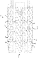
- Figure 8 illustrates an exemplary cabin arrangement 300 of the seat units 10, 100, 200 according to some embodiments of the present invention.
- the seat unit arrangement 300 When in a bed position or lounge position, the seat unit arrangement 300 provides a forward facing seat with a reverse herringbone bed/lounge.
- the cabin arrangement 300 includes three columns of seat units separated by aisles 301.
- the three columns of seat units include two side columns 310 and an inner column 312.
- Each row in the side columns 310 include a single seat unit 306 and each row in the inner column 312 includes two seat units 306.
- the seat units in the side columns 310 are arranged so that the side cushion 308 of each seat unit 306 is positioned closer to the adjoining cabin wall 303 and forward of the passenger seat.
- the seat units 306 in the inner column 312 are positioned so that the side cushion 308 of each seat unit 306 is positioned medially with respect to inner column 312 and forward of the passenger seat. In such a configuration, passengers may easily enter and exit each of the seat units 306 to the aisles 301.
- all seat units 306 provide the bed position and lounge position, it should be understood that not all units 306 must provide each position.
- the seat units 306 may provide a bed position, but not a lounge position.
- the seat units 306 may provide a lounge position but not a bed position.
- only some units 306 provide the bed position and only some units 306 provide the lounge position.
Landscapes
- Engineering & Computer Science (AREA)
- Aviation & Aerospace Engineering (AREA)
- Transportation (AREA)
- Mechanical Engineering (AREA)
- Seats For Vehicles (AREA)
- Special Chairs (AREA)
Description
- This application claims priority to and the benefit of
U.S. Provisional Application No. 61/719,053, filed on October 26, 2012 U.S. Provisional Application No. 61/811,141, filed on April 12, 2013 French Application No. FR13/53338 filed on April 12, 2013 - The present invention generally relates to passenger seats. More specifically, embodiments of the present invention relate to systems and methods for configuring aircraft seats and arranging aircraft seats in a passenger cabin.
- Usually, aircraft passenger seats are provided with a backrest that may rotate up and down around an axis perpendicular to the axis of the passenger seat. Using such a mechanism, some aircraft passenger seats may have a number of different seat positions. For example, some seats provide a fully flat/horizontal in flight bed position in addition to an upright seating position. In such designs, the bed may be defined by the seat backrest cushion and the pan cushion. Some designs also provide various intermediate positions between the upright seated position and the bed position. For example, some intermediate positions, such as a relaxed or snooze position, may be defined by a significant recline of the seat backrest. In some seat configurations that may transition to a bed position, a passenger must first vacate the seat before being able to transform the seat into the bed position.
- While the prior designs may provide various seat positions, further improvements can be made. It may be desirable to provide improved systems and methods for configuring a passenger seat so as to provide a new comfort position. Additionally, a passenger seat may be improved so as to allow a passenger to remain seated as the passenger seat is converted from the upright seated position to a horizontal bed position. Moreover, it may be desirable to provide improved systems and methods for configuring a passenger seat which provides a wider horizontal bed position. Further, it may be desirable to provide a new seat arrangement that allows passenger egress without disturbing other passengers, even when the seats of the other passengers are in a reclined or horizontal bed position.
- Document
EP1707486 describes a passenger seat arrangement comprising a seat and a couch joined permanently to the side of said seat. The upper surface of the seat and the upper surface of the couch are located at the same level, in such a way as to form a surface suitable for use as a bed. DocumentUS2001/000639 teaches the use of a bed extension connected to the footrest in a telescopic manner. - Document
EP1707486 is thereby considered being the closest prior art and discloses the preamble of independent claim 1. - The invention concerns a passenger seat arrangement as claimed in independent claim 1. The terms "invention," "the invention," "this invention" and "the present invention" used in this patent are intended to refer broadly to all of the subject matter of this patent and the patent claims below. Statements containing these terms should be understood not to limit the subject matter described herein or to limit the meaning or scope of the patent claims below. Embodiments of the invention covered by this patent arc defined by the claims below, not this summary. This summary is a high-level overview of various aspects of the invention and introduces some of the concepts that are further described in the Detailed Description section below. This summary is not intended to identify key or essential features of the claimed subject matter, nor is it intended to be used in isolation to determine the scope of the claimed subject matter. The subject matter should be understood by reference to appropriate portions of the entire specification of this patent, any or all drawings and each claim.
- In some embodiments, a seat unit is provided including a moving seat and a seat shell. The seat may be moved from an upright position to a bed position. In some embodiments, the seat axis may be different than the bed axis. In some embodiments the backrest may be used as a portion of the bed surface. Optionally, the seat pan may overlap with the backrest of the seat unit in front. For example, in some embodiments the seat pan may project into a seat backrest recess of the seat unit in front of the seat pan. Optionally, a portion of the seat pan may be retractable so as to reduce its length when transitioning between the upright position and the bed position. For example, in some embodiments, the front part of a seat pan may be retractable to accommodate available space. In some cases, the seat pan may overlap with the backrest of the seat unit in front and may include a retractable portion so as to reduce its length when transitioning between the upright position and the bed position.
- In some embodiments, a passenger seat arrangement is provided. The passenger seat may provide a plurality of different positions. The plurality of different positions may include a bed position and an upright position. The bed position may provide a bed surface being formed at least by a seat pan and one or more bed extensions. The one or more bed extensions may not form part of a seat surface or a footrest when the passenger seat is in the upright position. In some embodiments, the passenger seat may include a seat backrest and the seat backrest does not form part of the bed surface when the passenger seat is in the bed position.
- Optionally, the passenger seat comprises a seat backrest, and a bottom portion of the seat backrest may include a headrest cushion. The headrest cushion may be moveable to a deployed position to provide a headrest when the passenger seat is in the bed position. Additionally, the headrest cushion may be moveable to a stowed position when the passenger seat is in another position.
- In some embodiments, the bed extension may be stored under a seat pan. The passenger seat may further include a footrest and a seat mechanism for deploying the footrest and the bed extension in order to convert the passenger seat to the bed position.
- In additional embodiments, a side cushion may be positioned laterally and forward of the passenger seat. The passenger seat backrest may be rotatable towards the side cushion so as to provide a lounge position. The bed surface may comprise the seat pan cushion, the one or more bed extensions, and the side cushion. Optionally, the passenger seat may include a sensor for detecting the presence of a passenger to avoid conversion of the seat from the bed position to the upright position when a passenger is not seated properly.
- In some embodiments, the arrangement may include a plurality of passenger seats oriented substantially in an axis of a cabin. The seats may be arranged such that the seats have a herringbone bed arrangement.
- In another aspect of the invention, a passenger seat arrangement is provided. The passenger seat arrangement may include a passenger seat comprising a seat backrest and a seat pan. The passenger seat arrangement may further include a side cushion positioned laterally and forward of the passenger seat. The seat backrest may be rotatable between a forward facing position and a second position. The second position may face toward the side cushion. In some embodiments the seat backrest may rotate relative to the seat pan when the seat backrest rotates between the forward facing position and the second position. In other embodiments, the seat backrest and the seat pan may rotate together when the seat backrest rotates between the forward facing position and the second position.
- Optionally, the seat backrest may comprise a lower backrest and an upper backrest. The lower backrest may be rotatable between the forward facing position and the second position separately from the upper backrest. The lower backrest may be coupled with the seat pan and the upper backrest may be coupled with a privacy shell. In some embodiments, the upper backrest may be rotatable relative to the privacy shell.
- In some embodiments, the passenger seat may be moveable between an upright position and a bed position. The bed position may provide a substantially horizontal bed surface. The bed surface may include a bed extension and the bed extension may not form part of a seat surface or a footrest when the seat is in the upright position. Optionally, the seat backrest may not form part of the bed surface. Optionally, a lower portion of the seat backrest forms a part of the bed surface while an upper portion of the seat backrest does not form part of the bed surface.
- In yet another embodiment of the invention, a passenger seat arrangement for a cabin is provided. The cabin may be defined by cabin walls. The passenger seat arrangement may include a column of seat units adjacent to a cabin wall. The seat units may comprise a passenger seat and a side cushion positioned laterally and forward of the passenger seat. The side cushion and the passenger seat may define a footwell forward of the passenger seat. And the side cushions may be positioned lateral of the passenger seat on a side toward the cabin wall.
- A second column of seat units may be separated from the other column of seat units by an aisle. The seat units of the second column may also comprise a passenger seat and a side cushion positioned laterally and forward of the passenger seat and the side cushion and the passenger seat may define a footwell forward of the passenger seat. The seat unit footwells of the first column and the seat unit footwells of the second column may be accessible from the aisle. Optionally, at least one of the seat units is moveable from an upright position to a bed position or a lounge position. If the at least one seat unit is moveable to a bed position, the bed position may provide a substantially horizontal bed surface comprising at least the side cushion and the seat pan. If the at least one seat unit is moveable to the lounge position, the lounge position provides a seat backrest rotatable from a forward facing position to a second position. The second position facing toward the side cushion such that a passenger may comfortably rest their legs on the side cushion when seated in the passenger seat.
- The invention will be better understood on reading the following description and examining the figures that accompany it. These figures are provided by way of illustration only and are in no way limiting on the invention.
-
-
Figure 1 illustrates exemplary embodiments of the present invention; -
Figures 2A-2D illustrate exemplary embodiments of a seat unit and the exemplary conversion of a passenger seat when the seat unit is converted from an upright position to a bed position according to some embodiments of the invention; -
Figure 3 illustrates an exemplary backrest of a passenger seat according to some embodiments of the present invention; -
Figures 4A-4D illustrate exemplary embodiments of a seat unit that may move a seated passenger's body so that the passenger may remain seated on the seat as the seat transitions between a first position and a bed position according to some embodiments of the invention; -
Figures 5A-5C illustrate exemplary embodiments of a seat kinematic according to certain aspects of the invention; -
Figures 6A-6D illustrate exemplary embodiments of yet another seat kinematic according to certain aspects of the invention; -
Figures 7A-7C illustrate exemplary embodiments of a seat unit that may provide a novel comfort position; and -
Figure 8 illustrates an exemplary cabin arrangement of the seat units according to some embodiments of the present invention. - The subject matter of embodiments of the present invention is described here with specificity to meet statutory requirements, but this description is not necessarily intended to limit the scope of the claims. The claimed subject matter may be embodied in other ways, may include different elements or steps, and may be used in conjunction with other existing or future technologies. This description should not be interpreted as implying any particular order or arrangement among or between various steps or elements except when the order of individual steps or arrangement of elements is explicitly described.
-
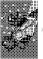
Figure 1 illustratesexemplary seat units 10 in various configurations according to some embodiments of the present invention. Theseat unit 10 may comprise aseat 12 and aside cushion 14 and may be convertible between abed position 16 and aupright position 18. In thebed position 16, the passenger may lie in a substantially horizontal position. In theupright position 18, theseat unit 10 may include a footwell 15 such that the passenger may be seated upright, generally in a forward facingdirection 20. - The
seat 12 may comprise aseat backrest 22 andseat pan 24.Side cushion 14 may be substantially horizontal to provide a restingsurface 26 and may extend laterally and forward fromseat pan 24.Seat pan 24 may be configured or reconfigured such that atop surface 28 ofseat pan 24 is substantially flush and horizontal with restingsurface 26. - To convert
seat unit 10 from theupright position 18 to thebed position 16, aportion 30 ofseat 12 may be moved to a horizontal position lateral toside cushion 14 and indirection 20 so as to form a part of the bed surface that extends over footwell 15. In some embodiments,portion 30 ofseat 12 may be a part of thebackrest cushion 22, theseat pan 24, a bed extension, and/or a footrest. In some embodiments, such as the exemplary embodiments illustrated inFigures 2A-2D and discussed in more detail below,portion 30 may comprise a bed extension and a footrest. Accordingly, the bed surface may compriseside surface 14 in addition to a part of thebackrest cushion 22, theseat pan 24, a bed extension, and/or a footrest. For example, in some embodiments abackrest cushion 22 may have an upper portion and a lower portion. The lower portion may form a bed surface withside surface 14,seat pan 24, a bed extension, and/or a footrest while the upper portion does not form a part of the bed surface. In other embodiments, such as the embodiment inFigures 2A-2D , the bed surface does not include a part of thebackrest cushion 22 but comprisesside surface 14 in addition toseat pan 24, a bed extension, and/or a footrest. In other embodiments, such as the ones illustrated inFigures 5 andFigures 6 , seat backrest cushion, seat pan, and side cushion may form the bed surface. -
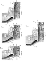
Figures 2A-2D illustrate exemplary embodiments of aseat unit 100 and the exemplary conversion of apassenger seat 110 whenseat unit 100 is converted from an upright position to a bed position according to some embodiments of the invention. Similar to the embodiments illustrated inFigure 1 ,seat unit 100 may includepassenger seat 110 and aside cushion 111.Side cushion 111 may provide a substantiallyhorizontal resting surface 113 adjacent to and extending forward frompassenger seat 110. The configuration ofpassenger seat 110 inFigure 2A may define an upright position ofpassenger seat 110 and the configuration ofpassenger seat 110 inFigure 2D may define a bed position ofpassenger seat 110.Figures 2B and 2C may illustrate the transition ofpassenger seat 110 from the upright position to the bed position. - As illustrated in
Figures 2A-2D ,passenger seat 110 may include aseat backrest 112, aseat pan 114, and/or afootrest 116.Passenger seat 110 may further include abed extension 118 that may be stored under aseat pan 114 or behindfootrest 116 when thepassenger seat 110 is in the upright position. Aseat mechanism 120 may be provided for coupling with theseat pan 114, thefootrest 116, and thebed extension 118. Theseat mechanism 120 may control the position and/or orientation ofseat pan 114,footrest 116, andbed extension 118 aspassenger seat 110 is repositioned between the upright position and the bed position. Details of the operation ofseat mechanism 120 may be greater appreciated inFigures 2B-2D . - As illustrated in
Figures 2B-2D ,seat mechanism 120 may moveseat pan 114 from a first position when thepassenger seat 110 is in the upright position to a second position when thepassenger seat 110 is in the bed position. As illustrated inFigure 2A , whenseat pan 114 is in the first position (i.e., when thepassenger seat 110 is in the upright position), atop surface 122 ofseat pan 114 may be at a slight angle relative to a horizontal plane.Figure 2D shows howseat mechanism 120 may rotate and/or translateseat pan 114 such that thetop surface 122 ofseat pan 114 is substantially horizontal when moved to the second position (i.e., when thepassenger seat 110 is in the bed position). Preferably,top surface 122 ofseat pan 114 is adjacent to, flush, and/or level with restingsurface 113 ofside cushion 111 whenseat pan 114 is in the second position. - Further,
seat mechanism 120 may move footrest 116 from a first position when thepassenger seat 110 is in the upright position to a second position when thepassenger seat 110 is in the bed position. As illustrated inFigure 2A , whenfootrest 116 is in the first position, a restingsurface 124 offootrest 116 may be in a substantially vertical position.Figure 2D shows howseat mechanism 120 may rotate and translatefootrest 116 such that the restingsurface 124 offootrest 116 is substantially horizontal when moved to the second position (i.e., when thepassenger seat 110 is in the bed position). Preferably, restingsurface 124 offootrest 116 is adjacent to, flush, and/or level with restingsurface 113 ofside cushion 111 whenfootrest 116 is in the second position. -
Seat mechanism 120 may also movebed extension 118 from the stored position when thepassenger seat 110 is in the upright position to a deployed position when thepassenger seat 110 is in the bed position. As discussed above and as illustrated inFigure 2A , whenpassenger seat 110 is in the upright position,bed extension 118 may be in the stored position and may be substantially concealed byseat pan 114 andfootrest 116. Aspassenger seat 110 transitions from the upright position to the bed position,seat mechanism 120 may rotate and/or translatebed extension 118 from the stored position to the deployed position where atop surface 126 ofbed extension 118 is substantially horizontal. Preferably,top surface 126 ofbed extension 118 is adjacent to, flush, and/or level with restingsurface 113 ofside cushion 111 whenbed extension 118 is in the deployed position. - As shown in
Figures 2A-2D ,seat mechanism 120 is configured to projectfootrest 116 forward a distance so as to allowbed extension 118 to fit betweenseat pan 114 andfootrest 116 when thepassenger seat 110 is transitioned from the upright position to the bed position. Accordingly,seat mechanism 120 is configured to moveseat pan 114,bed extension 118, andfootrest 116 adjacent to one another such that thesurfaces surface 113 ofside cushion 111. - Further while
passenger seat 110 has been illustrated with onebed extension 118, other embodiments may use more than onebed extension 118. Additionally,Figures 2A-2D show embodiments whereseat mechanism 120 automatically transitionsseat pan 114,footrest 116, andbed extension 118 in unison as thepassenger seat 110 is transitioned between the upright position and the bed position. In other embodiments,bed extension 118 may not be coupled with theseat mechanism 120. For example, in some embodiments,bed extension 118 may be manually positioned and/or removed afterseat mechanism 120 has repositionedseat pan 114 andfootrest 116. Moreover,seat mechanism 120 may be manually driven or driven by an electric actuator. WhileFigures 2A-2D illustrate aseat mechanism 120 that positionsbed extension 118 betweenseat pan 114 andfootrest 116, other seat mechanism configurations are possible that may provide alternative arrangements of the components whenpassenger seat 110 is converted to the bed position. Advantageously, theadditional side cushion 111 may provide a wider bed surface whenseat 110 is in the bed position. - In the illustrated embodiment,
seat backrest 112 may not be needed to form part of the bed surface. Optionally, in some embodiments, such as the embodiment illustrated inFigure 3 , a bottom portion ofseat backrest 112 may comprise a deployable headrest 130. The deployable headrest 130 may be moveable between a stowed position and a deployed position. When in the stowed position, the deployable headrest 130 may form part of the bottom portion of theseat backrest 112. When deployed, the deployable headrest 130 may provide a headrest for supporting a passenger's head when the passenger seat is in the bed position. In some embodiments, a pull tab may couple with an end of the headrest 130 to facilitate manual deployment of the headrest 130 to the deployed position. Optionally, headrest 130 may be moved between the deployed and the stowed position using an electric actuator. - In some embodiments, a seat unit may move a seated passenger's body so that the passenger may remain seated on the seat as the seat transitions between a first position and a bed position as shown in
Figures 4A-4D .Figure 4A illustrates a passenger seated inpassenger seat 110 whenpassenger seat 110 is in an upright position.Figure 4B illustrates an intermediate position ofpassenger seat 110 aspassenger seat 110 moves toward the bed position.Footrest 116 may rotate and project forward toward the bed position so as to raise the seated passenger's legs and to allowbed extension 118 to move from the stowed position toward the bed position.Figure 4C illustratespassenger seat 110 in the bed position with the passenger seated. Once in the bed position, the passenger may reposition himself/herself from the seated position to a lying position across the bed surface comprising theseat pan 114,bed extension 118,footrest 116 andside cushion 111. In some embodiments, the seat unit may include a sensor to prevent the seat unit from returning to the upright position from the bed position when the passenger is in a lying position across the bed surface. For example,passenger seat 110 may include a pressure sensor to detect the presence of a lying passenger. When the passenger is lying, the sensor may preventpassenger seat 110 from returning to an upright position. In some embodiments, thepassenger seat 110 may wait till the passenger is properly seated or vacant from the seat before transitioning from the bed position back to the upright position. -
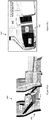
Figures 5A-5C illustrate an exemplary embodiment of aseat unit 400 including apassenger seat 402, where the bed surface is formed by aseat backrest 410, aseat pan 412, and aside cushion 414.Figure 5A(s)-5A(t) illustrate the side and top views ofseat unit 400 when thepassenger seat 402 is in the upright position.Figure 5C(s)-5C(t) illustrate the side and top views ofseat unit 400 when thepassenger seat 402 is in the bed position.Figures 5B illustrate the side and top views ofseat unit 400 as thepassenger seat 402 is moved between the upright position and the bed position. - Optionally,
passenger seat 402 may include afoot rest 416. In some embodiments, pitch betweenseat unit 400 andseat unit 500 may be fixed or limited. As illustrated inFigures 5A-5C ((s) and (t) views),seat backrest 410 may recline from the upright position to a substantially horizontal position flush withside cushion 414. In order to accommodate the length ofseat backrest 410 and the movement ofseat backrest 410 to the horizontal position,seat pan 412 may be projected in aforward direction 415 from the upright position toward the bed position. In some embodiments,seat pan 412 may extend into arecess 501 of theseat unit 500 in front ofseat unit 400. Recess 501 may also be configured to accommodatefootrest 416. Accordingly, in some embodiments,seat pan 412 may overlap with theseat backrest 510 of theseat unit 500. As illustrated inFigure 5C ((s) and (t) views), once in the bed position,seat backrest 410,seat pan 412, andside cushion 414 may provide a bed surface. -
Figures 6A-6D ((s) and (t) views) illustrate an exemplary embodiment of aseat unit 600 including apassenger seat 602, where the bed surface is formed byseat backrest 610,seat pan 612, andside cushion 614.Figures 6A(s)-6A(t) illustrate the side and top views ofseat unit 600 when thepassenger seat 602 is in the upright position.Figure 6D(s)-6D(t) illustrate the side and top views ofseat unit 600 when thepassenger seat 602 is in the bed position.Figures 6B-6C ((s) and (t) views) illustrate the side and top views ofseat unit 600 as thepassenger seat 602 is moved between the upright position and the bed position. -
Seat pan 612 ofpassenger seat 602 may include aretractable portion 616.Retractable portion 616 may retract so as to shorten a length ofseat pan 612. In some embodiments, theretractable cushion 616 may be a telescoping design, accordion design, etc. The fabric cover ofretractable portion 616 may be stretchable or compressible. - Accordingly, in some embodiments, as
seat backrest 610 may recline from the upright position to a substantially horizontal position flush withside cushion 414, as illustrated inFigures 6A-6D ((s) and (t) views). A pitch between seat rows may be limited or fixed. Thus, asseat backrest 610 reclines to the horizontal position and as shown inFigures 6B-6D ((s) and (t) views),retractable portion 616 ofseat pan 612 may retract so as to accommodate the length ofseat backrest 610 and the movement ofseat backrest 610 to the horizontal position. Whenseat backrest 610 is in the horizontal position, theretractable portion 616 may be fully retracted. Once in the bed position,seat backrest 610,seat pan 612, andside cushion 614 may provide a bed surface. When returning to the upright position,retractable portion 616 may expand so as to extend a length ofseat pan 612 when thepassenger seat 610 is in the upright position. - While the embodiments disclosed above are discussed separately, it should be understood that some aspects of each embodiment may be combinable with aspects of another embodiment. For example, in some embodiments, a seat pan of a passenger seat may include a retractable portion and may be extend into a recess of the seat unit in front of the passenger seat. In some embodiments, the seat backrest may not form a portion of a bed surface and the seat pan may include a retractable portion. In some embodiments, the seat backrest may not form a portion of the bed surface and a seat pan or footrest may extend into a recess of the seat unit in front of the passenger seat.
- Optionally, in some embodiments, a seat unit may provide a novel comfort position as shown in
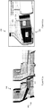
Figures 7A-7C . Similar to the embodiments discussed above,seat units 200 may include apassenger seat 210 and aside cushion 211.Side cushion 211 may provide a substantiallyhorizontal resting surface 213 adjacent to and extending forward frompassenger seat 210.Passenger seat 210 may include aseat backrest 212 and aseat pan 214. Theseat backrest 212 may be reclineablerelative seat pan 214. The configuration ofseat unit 200/passenger seat 210 inFigures 7A-7C may define a "lounge" position in which theseat backrest 212 is rotated in thedirection 215 toward theside cushion 211. In such a position,passenger seat 210 may comfortably position a seated passenger such that the passenger may easily rest one or both legs onside cushion 213 without having to convertseat unit 200 to a bed position. Accordingly,seat backrest 212 may be rotatable on multiple axes to offer maximum comfort to the passenger. - In some embodiments, the
backrest 212 may also be in more than one portion. For example,Figure 7B shows an embodiment whereseatback rest 212 may comprise anupper backrest 216 and alower backrest 218. In some embodiments,seat unit 200 may be in the lounge position when thelower backrest 218 rotates indirection 215 towardside cushion 211. Optionally, as shown inFigure 7C ,upper backrest 216 andlower backrest 218 may rotate together indirection 215 to convertseat unit 200/passenger seat 210 into the lounge position. In some embodiments, thelower backrest 218 may be coupled with theseat pan 214 whileseat backrest 216 couples with the privacy shell 220. It should be understood that some seat unit embodiments may provide the lounge position in addition to the bed position described above. - While
seat units passenger seats - In some embodiments of the invention, a cabin arrangement is provided.
Figure 8 illustrates anexemplary cabin arrangement 300 of theseat units seat unit arrangement 300 provides a forward facing seat with a reverse herringbone bed/lounge. Thecabin arrangement 300 includes three columns of seat units separated byaisles 301. The three columns of seat units include twoside columns 310 and aninner column 312. Each row in theside columns 310 include asingle seat unit 306 and each row in theinner column 312 includes twoseat units 306. The seat units in theside columns 310 are arranged so that theside cushion 308 of eachseat unit 306 is positioned closer to the adjoiningcabin wall 303 and forward of the passenger seat. Theseat units 306 in theinner column 312 are positioned so that theside cushion 308 of eachseat unit 306 is positioned medially with respect toinner column 312 and forward of the passenger seat. In such a configuration, passengers may easily enter and exit each of theseat units 306 to theaisles 301. - While
cabin arrangement 300 is illustrated as providing forward facingseat units 306, it should be understood thatcabin arrangement 300 may also provide for a backward facingseat unit 306 arrangement. Further some narrow cabins may be limited to twoside columns 310 and possibly only asingle side column 310. Wider cabins may include more than oneinner column 312. In some embodiments, two, three, four, or moreinner columns 312 may be provided. In alternative embodiments,inner columns 312 may only have asingle seat unit 306 in each row. In such an embodiment, it may be preferable to arrange theseat units 306 such that the side cushions 308 are positioned on the same side of thecolumn 312 so as to save space and/or accommodateadditional seat units 306. - Further, while it may be preferable that all
seat units 306 provide the bed position and lounge position, it should be understood that not allunits 306 must provide each position. In some embodiments, theseat units 306 may provide a bed position, but not a lounge position. In other embodiments, theseat units 306 may provide a lounge position but not a bed position. In further embodiments, only someunits 306 provide the bed position and only someunits 306 provide the lounge position. - Different arrangements of the components depicted in the drawings or described above, as well as components and steps not shown or described are possible. Similarly, some features and sub-combinations are useful and may be employed without reference to other features and sub-combinations. Embodiments of the invention have been described for illustrative and not restrictive purposes, and alternative embodiments will become apparent to readers of this patent. Accordingly, the present invention is not limited to the embodiments described above or depicted in the drawings, and various embodiments and modifications may be made without departing from the scope of the claims below.
Claims (15)
- A passenger seat arrangement comprising:a passenger seat (110) that provides a plurality of different positions, the plurality of different positions including a bed position and an upright position, the bed position providing a bed surface being formed at least by a seat pan (114) and one or more bed extensions (118); andwherein the one or more bed extensions (118) do not form part of a seat surface or a footrest when the passenger seat (110) is in the upright position,characterized in that the bed extension (118) is stored under the seat pan (114); and wherein the passenger seat (110) further comprises a footrest (116) and a seat mechanism (120) for deploying the footrest (116) and the bed extension (118) in order to convert the passenger seat (110) to the bed position, and in that the seat mechanism (120) is configured to project footrest (116) forward a distance so as to allow bed extension (118) to fit between the seat pan (114) and the footrest (116) when the passenger seat (110) is transitioned from the upright position to the bed position, wherein the seat mechanism (120) is configured to move seat pan (114), bed extension (118), and footrest (116) adjacent to one another such that the surfaces (122), (124), (126) of each component are substantially flush and horizontal so as to form a bed surface.
- The passenger seat arrangement of claim 1, characterized in that the passenger seat (110) comprises a seat backrest (112); and in that the seat backrest (112) does not form part of the bed surface when the passenger seat (110) is in the bed position.
- The passenger seat arrangement of claim 1, characterized in that the passenger seat comprises a seat backrest (112); and wherein a bottom portion of the seat backrest (112) comprises a headrest cushion, the headrest cushion moveable to a deployed position to provide a headrest when the passenger seat (110) is in the bed position and moveable to a stowed position when the passenger seat (110) is in another position.
- The passenger seat arrangement of any of claims 1 to 3, further comprising a side cushion (111) positioned laterally and forward of the passenger seat.
- The passenger seat arrangement of claim 4, wherein the passenger seat backrest (112) is rotatable towards the side cushion (111) so as to provide a lounge position.
- The passenger seat arrangement of any of claims 1 to 5, characterized in that a bed surface comprises the seat pan (114), the one or more bed extensions (118), and the side cushion (111).
- The passenger seat arrangement of any of claims 1 to 6, characterized in that it further comprises a sensor for detecting the presence of a passenger to avoid conversion of the seat from the bed position to the upright position when a passenger is not seated.
- The passenger seat arrangement of any of claims 1 to 7, characterized in that it further comprises a plurality of passenger seats (110) oriented substantially in an axis of a cabin, the seats arranged such that the seats have a herringbone bed arrangement.
- The passenger seat arrangement of any of the claims 1 to 8, characterized in that it comprises:a passenger seat (110) comprising a seat backrest (112) and a seat pan (114);a side cushion (111) positioned laterally and forward of the passenger seat; andwherein the seat backrest (112) is rotatable between a forward facing position and a second position, the second position facing toward the side cushion (111).
- The passenger seat arrangement of claim 9, characterized in that the seat backrest (112) rotates relative to the seat pan (114) when the seat backrest (112) rotates between the forward facing position and the second position.
- The passenger seat arrangement of claim 9, characterized in that the seat backrest (112) and the seat pan (114) rotate together when the seat backrest (112) rotates between the forward facing position and the second position.
- The passenger seat arrangement of any of claims 9 to 11, characterized in that the seat backrest (112) comprises a lower backrest and an upper backrest, and wherein the lower backrest is rotatable between the forward facing position and the second position separately from the upper backrest.
- The passenger seat arrangement of claim 12, characterized in that the lower backrest is coupled with the seat pan and wherein the upper backrest is coupled with a privacy shell.
- The passenger seat arrangement of claim 13, characterized in that the upper backrest is rotatable relative to the privacy shell.
- The passenger seat arrangement according to any of the claims 1 to 14 for a cabin defined by cabin walls, the passenger seat arrangement characterized it comprises:a column of seat units (100) adjacent to a cabin wall, the seat units (100) comprising a passenger seat (110) and a side cushion (111) positioned laterally and forward of the passenger seat (110), the side cushion (111) and the passenger seat (110) defining a footwell forward of the passenger seat (110); andwherein the side cushions (111) are positioned lateral of the passenger seat on a side toward the cabin wall.
Applications Claiming Priority (4)
| Application Number | Priority Date | Filing Date | Title |
|---|---|---|---|
| US201261719053P | 2012-10-26 | 2012-10-26 | |
| US201361811141P | 2013-04-12 | 2013-04-12 | |
| FR1353338A FR3004419B1 (en) | 2013-04-12 | 2013-04-12 | CABIN ARRANGEMENT BUSINESS CLASS. |
| PCT/IB2013/002630 WO2014064525A2 (en) | 2012-10-26 | 2013-10-28 | Aircraft seat configuration and arrangement systems and methods |
Publications (2)
| Publication Number | Publication Date |
|---|---|
| EP2911938A2 EP2911938A2 (en) | 2015-09-02 |
| EP2911938B1 true EP2911938B1 (en) | 2017-04-12 |
Family
ID=48613981
Family Applications (1)
| Application Number | Title | Priority Date | Filing Date |
|---|---|---|---|
| EP13808209.4A Active EP2911938B1 (en) | 2012-10-26 | 2013-10-28 | Aircraft seat configuration and arrangement systems and methods |
Country Status (5)
| Country | Link |
|---|---|
| US (1) | US9856025B2 (en) |
| EP (1) | EP2911938B1 (en) |
| JP (1) | JP6475628B2 (en) |
| FR (1) | FR3004419B1 (en) |
| WO (1) | WO2014064525A2 (en) |
Families Citing this family (36)
| Publication number | Priority date | Publication date | Assignee | Title |
|---|---|---|---|---|
| US9592914B2 (en) | 2011-10-07 | 2017-03-14 | Bombardier Inc. | Aircraft seat |
| US9714862B2 (en) | 2011-10-07 | 2017-07-25 | Bombardier Inc. | Aircraft seat |
| US9714095B2 (en) | 2011-10-07 | 2017-07-25 | Bombardier Inc. | Aircraft seat |
| US10583926B2 (en) | 2014-09-25 | 2020-03-10 | Bombardier Inc. | Aircraft seat |
| GB2530557A (en) * | 2014-09-26 | 2016-03-30 | Bombardier Inc | Aircraft seat |
| GB2530556A (en) * | 2014-09-26 | 2016-03-30 | Bombardier Inc | Aircraft seat |
| US9694755B2 (en) * | 2014-11-26 | 2017-07-04 | GM Global Technology Operations LLC | Seat assembly with removable cushion insert |
| EP3280641B1 (en) * | 2015-04-08 | 2020-01-29 | Safran Seats USA LLC | Universal rest seats |
| US10549857B2 (en) * | 2015-09-29 | 2020-02-04 | B/E Aerospace, Inc. | Airliner passenger suite seating arrangements with shared aisle suite access |
| US9855860B2 (en) | 2016-05-19 | 2018-01-02 | Waymo Llc | Second row priority seating for vehicles |
| US11498461B2 (en) | 2017-02-17 | 2022-11-15 | Safran Seats Usa Llc | Passenger seat with comfort layout |
| US10988055B2 (en) | 2017-03-17 | 2021-04-27 | Safran Seats Usa Llc | Passenger seat with movable backrest portion |
| USD885280S1 (en) | 2017-03-30 | 2020-05-26 | Zoox, Inc. | Vehicle headrest |
| US10875435B1 (en) * | 2017-03-30 | 2020-12-29 | Zoox, Inc. | Headrest with passenger flaps |
| WO2018178246A1 (en) * | 2017-03-31 | 2018-10-04 | Zodiac Seats France | Arrangement of individual seats for passengers of an aeroplane |
| GB2572556A (en) | 2018-03-30 | 2019-10-09 | Acumen Design Ass Ltd | A passenger seating arrangement having a screen between seat units |
| EP4046913B1 (en) * | 2018-04-04 | 2024-06-05 | Zephyr Aerospace, LLC | Vehicular seating suite configuration |
| US10604261B2 (en) | 2018-04-09 | 2020-03-31 | B/E Aerospace, Inc. | Movable ottoman for an aircraft seat |
| US10899458B2 (en) | 2018-05-21 | 2021-01-26 | The Boeing Company | Sleep systems for aircraft |
| USD895312S1 (en) | 2018-05-21 | 2020-09-08 | The Boeing Company | Lateral sleep apparatus |
| USD911899S1 (en) * | 2018-05-21 | 2021-03-02 | The Boeing Company | Panel |
| USD917906S1 (en) * | 2019-03-28 | 2021-05-04 | Airbus Interiors Services Sas | Seat arrangement |
| USD911726S1 (en) * | 2019-04-03 | 2021-03-02 | Zephyr Aerospace, LLC | Vehicular seating suite arrangement |
| USD909783S1 (en) * | 2019-04-03 | 2021-02-09 | Zephyr Aerospace, LLC | Vehicular seating suite arrangement |
| USD911725S1 (en) * | 2019-04-03 | 2021-03-02 | Zephyr Aerospace, LLC | Vehicular seating suite arrangement |
| GB2583964B (en) * | 2019-05-16 | 2022-06-08 | Safran Seats Gb Ltd | An aircraft passenger seat unit |
| US11447252B2 (en) * | 2019-10-01 | 2022-09-20 | B/E Aerospace, Inc. | Aircraft seat with separated seat back and seat pan |
| GB2592687B (en) | 2020-03-06 | 2024-02-28 | Acumen Design Ass Ltd | Outboard facing herringbone seating arrangement |
| DE102020108436A1 (en) * | 2020-03-26 | 2021-09-30 | Recaro Aircraft Seating Gmbh & Co. Kg | Aircraft seating arrangement |
| US11708163B2 (en) | 2020-10-02 | 2023-07-25 | B/E Aerospace, Inc. | Static aircraft seat privacy panels |
| US12049319B2 (en) | 2020-10-02 | 2024-07-30 | B/E Aerospace, Inc. | Slanted aircraft seat privacy panels |
| USD994358S1 (en) | 2021-02-02 | 2023-08-08 | Zephyr Aerospace, LLC | Vehicular seating suite |
| DE102021117964A1 (en) * | 2021-07-12 | 2023-01-12 | Recaro Aircraft Seating Gmbh & Co. Kg | aircraft seat arrangement |
| US12071244B2 (en) * | 2021-12-15 | 2024-08-27 | The Boeing Company | Reconfigurable seat assembly |
| FR3154103B1 (en) * | 2023-10-17 | 2025-08-29 | Safran Seats | SEAT WITH BED EXTENSION WITH IMPROVED DEPLOYMENT KINEMATICS |
| FR3166883A1 (en) * | 2024-10-02 | 2026-04-03 | Safran Seats | SEAT EQUIPPED WITH A BED EXTENSION WITH IMPROVED DEPLOYMENT KINEMATICS |
Family Cites Families (20)
| Publication number | Priority date | Publication date | Assignee | Title |
|---|---|---|---|---|
| US2632408A (en) * | 1951-10-04 | 1953-03-24 | Giles Eugene Manning | Compartmentizable seat for railroad coaches and the like |
| JPH058192Y2 (en) * | 1986-05-31 | 1993-03-02 | ||
| JP2999646B2 (en) * | 1993-03-02 | 2000-01-17 | 小糸工業株式会社 | Seat equipment |
| US20010000639A1 (en) * | 1997-02-20 | 2001-05-03 | Singapore Airlines Ltd. | Transport accommodation |
| CA2625280C (en) * | 2001-08-09 | 2010-08-03 | Virgin Atlantic Airways Limited | A seating system and a passenger accomodation unit for a vehicle |
| US6916069B2 (en) * | 2002-05-07 | 2005-07-12 | Recaro Aircraft Seating Gmbh & Co. | Seat |
| FR2842498B1 (en) * | 2002-07-19 | 2005-05-13 | Airbus | AIRCRAFT CABIN MODULE |
| JP2005297897A (en) * | 2004-04-15 | 2005-10-27 | Nissan Motor Co Ltd | Vehicle seat |
| GB0425323D0 (en) * | 2004-11-17 | 2004-12-22 | Britax Aircraft Interiors Uk L | Aircraft seat |
| FR2883838B1 (en) * | 2005-03-31 | 2007-06-08 | Eads Sogerma Services Soc Par | FURNITURE PIECE FOR A VEHICLE, IN PARTICULAR FOR AN AIRCRAFT |
| JP4827928B2 (en) * | 2005-11-24 | 2011-11-30 | シンガポール エアラインズ リミテッド | Aircraft seats and seat arrangements |
| SG168521A1 (en) | 2005-12-23 | 2011-02-28 | British Airways Plc | Aircraft passenger seat |
| GB2438162A (en) * | 2006-05-19 | 2007-11-21 | British Airways Plc | Reclining aircraft seat convertible into bed |
| GB0724397D0 (en) * | 2007-12-14 | 2008-01-30 | Premium Aircraft Interiors Gro | Aircraft seat |
| DE102007062573A1 (en) * | 2007-12-22 | 2009-06-25 | Daimler Ag | Seat arrangement for use in passenger cabin for motor vehicle, comprises rear vehicle seat which is adjusted from seating position into couch position, where front vehicle seat moves from seating position into alternate position |
| GB0816741D0 (en) | 2008-09-12 | 2008-10-22 | American Airlines | Array of aircraft seats - interlocking herringbone |
| US8876202B2 (en) * | 2009-07-16 | 2014-11-04 | The Boeing Company | Berth sleeper system |
| FR2953168B1 (en) * | 2009-12-02 | 2012-01-06 | Eads Sogerma | CONVERTIBLE SEAT IN SLEEVE |
| US8457846B2 (en) * | 2010-05-14 | 2013-06-04 | Crane Co. | Modular seat actuation control system and communication method |
| ITUB20153008A1 (en) * | 2015-08-07 | 2017-02-07 | Optimares S P A | Aircraft seat assembly. |
-
2013
- 2013-04-12 FR FR1353338A patent/FR3004419B1/en active Active
- 2013-10-28 US US14/437,509 patent/US9856025B2/en active Active
- 2013-10-28 JP JP2015538584A patent/JP6475628B2/en active Active
- 2013-10-28 EP EP13808209.4A patent/EP2911938B1/en active Active
- 2013-10-28 WO PCT/IB2013/002630 patent/WO2014064525A2/en not_active Ceased
Non-Patent Citations (1)
| Title |
|---|
| None * |
Also Published As
| Publication number | Publication date |
|---|---|
| JP2016500610A (en) | 2016-01-14 |
| WO2014064525A2 (en) | 2014-05-01 |
| WO2014064525A3 (en) | 2014-10-30 |
| FR3004419A1 (en) | 2014-10-17 |
| EP2911938A2 (en) | 2015-09-02 |
| US20150298812A1 (en) | 2015-10-22 |
| JP6475628B2 (en) | 2019-02-27 |
| US9856025B2 (en) | 2018-01-02 |
| FR3004419B1 (en) | 2016-04-29 |
Similar Documents
| Publication | Publication Date | Title |
|---|---|---|
| US9856025B2 (en) | Aircraft seat configuration and arrangement systems and methods | |
| US11787545B2 (en) | Platform first class | |
| EP2948372B1 (en) | Bed extension | |
| EP3581496B1 (en) | Seat unit for a vehicle cabin | |
| JP5097208B2 (en) | Moving and rotatable passenger seat | |
| EP2234884B1 (en) | Aircraft passenger seat | |
| EP1495908B1 (en) | A seating system and a passenger accomodation unit for a vehicle | |
| EP2697116B1 (en) | Passenger seating arrangements | |
| EP2019777B1 (en) | Aircraft passenger seat | |
| US9216826B2 (en) | Aircraft seating configuration | |
| JP6046917B2 (en) | Convertible seat to bed | |
| EP3689748B1 (en) | Deployable infill assembly and passenger seat construction | |
| US20120292957A1 (en) | Seat that can be converted into a sleeping-berth | |
| US20120318918A1 (en) | Flexible-usage travel suite | |
| US20200216177A1 (en) | Arrangement of individual seats for passengers of an aeroplane equipped with screen supports forming a separating wall | |
| US20220033083A1 (en) | Passenger seat unit for an aircraft cabin | |
| JP2019534201A (en) | Passenger seat arrangement with retractable armrest | |
| EP2907754A1 (en) | Aircraft passenger seating arrangements | |
| HK1128665B (en) | Aircraft passenger seat | |
| HK1068209C (en) | A seating system and a passenger accomodation unit for a vehicle | |
| HK1068209B (en) | A seating system and a passenger accomodation unit for a vehicle | |
| HK1154831B (en) | A seating system and a passenger seat unit for an aircraft |
Legal Events
| Date | Code | Title | Description |
|---|---|---|---|
| PUAI | Public reference made under article 153(3) epc to a published international application that has entered the european phase |
Free format text: ORIGINAL CODE: 0009012 |
|
| 17P | Request for examination filed |
Effective date: 20150416 |
|
| AK | Designated contracting states |
Kind code of ref document: A2 Designated state(s): AL AT BE BG CH CY CZ DE DK EE ES FI FR GB GR HR HU IE IS IT LI LT LU LV MC MK MT NL NO PL PT RO RS SE SI SK SM TR |
|
| AX | Request for extension of the european patent |
Extension state: BA ME |
|
| DAX | Request for extension of the european patent (deleted) | ||
| REG | Reference to a national code |
Ref country code: DE Ref legal event code: R079 Ref document number: 602013019843 Country of ref document: DE Free format text: PREVIOUS MAIN CLASS: B64D0011060000 Ipc: B60N0002005000 |
|
| GRAP | Despatch of communication of intention to grant a patent |
Free format text: ORIGINAL CODE: EPIDOSNIGR1 |
|
| RIC1 | Information provided on ipc code assigned before grant |
Ipc: B60N 2/34 20060101ALI20170111BHEP Ipc: B60N 2/005 20060101AFI20170111BHEP Ipc: B60N 2/00 20060101ALI20170111BHEP Ipc: B60N 2/24 20060101ALI20170111BHEP Ipc: B60N 2/44 20060101ALI20170111BHEP Ipc: B60N 2/22 20060101ALI20170111BHEP Ipc: B64D 11/06 20060101ALI20170111BHEP Ipc: B60N 2/01 20060101ALI20170111BHEP |
|
| INTG | Intention to grant announced |
Effective date: 20170125 |
|
| GRAS | Grant fee paid |
Free format text: ORIGINAL CODE: EPIDOSNIGR3 |
|
| GRAA | (expected) grant |
Free format text: ORIGINAL CODE: 0009210 |
|
| AK | Designated contracting states |
Kind code of ref document: B1 Designated state(s): AL AT BE BG CH CY CZ DE DK EE ES FI FR GB GR HR HU IE IS IT LI LT LU LV MC MK MT NL NO PL PT RO RS SE SI SK SM TR |
|
| REG | Reference to a national code |
Ref country code: GB Ref legal event code: FG4D |
|
| REG | Reference to a national code |
Ref country code: CH Ref legal event code: EP |
|
| REG | Reference to a national code |
Ref country code: IE Ref legal event code: FG4D |
|
| REG | Reference to a national code |
Ref country code: AT Ref legal event code: REF Ref document number: 883496 Country of ref document: AT Kind code of ref document: T Effective date: 20170515 |
|
| REG | Reference to a national code |
Ref country code: DE Ref legal event code: R096 Ref document number: 602013019843 Country of ref document: DE |
|
| REG | Reference to a national code |
Ref country code: NL Ref legal event code: MP Effective date: 20170412 |
|
| REG | Reference to a national code |
Ref country code: LT Ref legal event code: MG4D |
|
| REG | Reference to a national code |
Ref country code: AT Ref legal event code: MK05 Ref document number: 883496 Country of ref document: AT Kind code of ref document: T Effective date: 20170412 |
|
| PG25 | Lapsed in a contracting state [announced via postgrant information from national office to epo] |
Ref country code: NL Free format text: LAPSE BECAUSE OF FAILURE TO SUBMIT A TRANSLATION OF THE DESCRIPTION OR TO PAY THE FEE WITHIN THE PRESCRIBED TIME-LIMIT Effective date: 20170412 |
|
| PG25 | Lapsed in a contracting state [announced via postgrant information from national office to epo] |
Ref country code: NO Free format text: LAPSE BECAUSE OF FAILURE TO SUBMIT A TRANSLATION OF THE DESCRIPTION OR TO PAY THE FEE WITHIN THE PRESCRIBED TIME-LIMIT Effective date: 20170712 Ref country code: ES Free format text: LAPSE BECAUSE OF FAILURE TO SUBMIT A TRANSLATION OF THE DESCRIPTION OR TO PAY THE FEE WITHIN THE PRESCRIBED TIME-LIMIT Effective date: 20170412 Ref country code: AT Free format text: LAPSE BECAUSE OF FAILURE TO SUBMIT A TRANSLATION OF THE DESCRIPTION OR TO PAY THE FEE WITHIN THE PRESCRIBED TIME-LIMIT Effective date: 20170412 Ref country code: LT Free format text: LAPSE BECAUSE OF FAILURE TO SUBMIT A TRANSLATION OF THE DESCRIPTION OR TO PAY THE FEE WITHIN THE PRESCRIBED TIME-LIMIT Effective date: 20170412 Ref country code: FI Free format text: LAPSE BECAUSE OF FAILURE TO SUBMIT A TRANSLATION OF THE DESCRIPTION OR TO PAY THE FEE WITHIN THE PRESCRIBED TIME-LIMIT Effective date: 20170412 Ref country code: HR Free format text: LAPSE BECAUSE OF FAILURE TO SUBMIT A TRANSLATION OF THE DESCRIPTION OR TO PAY THE FEE WITHIN THE PRESCRIBED TIME-LIMIT Effective date: 20170412 Ref country code: GR Free format text: LAPSE BECAUSE OF FAILURE TO SUBMIT A TRANSLATION OF THE DESCRIPTION OR TO PAY THE FEE WITHIN THE PRESCRIBED TIME-LIMIT Effective date: 20170713 |
|
| REG | Reference to a national code |
Ref country code: FR Ref legal event code: PLFP Year of fee payment: 5 |
|
| PG25 | Lapsed in a contracting state [announced via postgrant information from national office to epo] |
Ref country code: IS Free format text: LAPSE BECAUSE OF FAILURE TO SUBMIT A TRANSLATION OF THE DESCRIPTION OR TO PAY THE FEE WITHIN THE PRESCRIBED TIME-LIMIT Effective date: 20170812 Ref country code: RS Free format text: LAPSE BECAUSE OF FAILURE TO SUBMIT A TRANSLATION OF THE DESCRIPTION OR TO PAY THE FEE WITHIN THE PRESCRIBED TIME-LIMIT Effective date: 20170412 Ref country code: SE Free format text: LAPSE BECAUSE OF FAILURE TO SUBMIT A TRANSLATION OF THE DESCRIPTION OR TO PAY THE FEE WITHIN THE PRESCRIBED TIME-LIMIT Effective date: 20170412 Ref country code: BG Free format text: LAPSE BECAUSE OF FAILURE TO SUBMIT A TRANSLATION OF THE DESCRIPTION OR TO PAY THE FEE WITHIN THE PRESCRIBED TIME-LIMIT Effective date: 20170712 Ref country code: LV Free format text: LAPSE BECAUSE OF FAILURE TO SUBMIT A TRANSLATION OF THE DESCRIPTION OR TO PAY THE FEE WITHIN THE PRESCRIBED TIME-LIMIT Effective date: 20170412 Ref country code: PL Free format text: LAPSE BECAUSE OF FAILURE TO SUBMIT A TRANSLATION OF THE DESCRIPTION OR TO PAY THE FEE WITHIN THE PRESCRIBED TIME-LIMIT Effective date: 20170412 |
|
| REG | Reference to a national code |
Ref country code: DE Ref legal event code: R097 Ref document number: 602013019843 Country of ref document: DE |
|
| PG25 | Lapsed in a contracting state [announced via postgrant information from national office to epo] |
Ref country code: DK Free format text: LAPSE BECAUSE OF FAILURE TO SUBMIT A TRANSLATION OF THE DESCRIPTION OR TO PAY THE FEE WITHIN THE PRESCRIBED TIME-LIMIT Effective date: 20170412 Ref country code: RO Free format text: LAPSE BECAUSE OF FAILURE TO SUBMIT A TRANSLATION OF THE DESCRIPTION OR TO PAY THE FEE WITHIN THE PRESCRIBED TIME-LIMIT Effective date: 20170412 Ref country code: SK Free format text: LAPSE BECAUSE OF FAILURE TO SUBMIT A TRANSLATION OF THE DESCRIPTION OR TO PAY THE FEE WITHIN THE PRESCRIBED TIME-LIMIT Effective date: 20170412 Ref country code: CZ Free format text: LAPSE BECAUSE OF FAILURE TO SUBMIT A TRANSLATION OF THE DESCRIPTION OR TO PAY THE FEE WITHIN THE PRESCRIBED TIME-LIMIT Effective date: 20170412 Ref country code: EE Free format text: LAPSE BECAUSE OF FAILURE TO SUBMIT A TRANSLATION OF THE DESCRIPTION OR TO PAY THE FEE WITHIN THE PRESCRIBED TIME-LIMIT Effective date: 20170412 |
|
| PLBE | No opposition filed within time limit |
Free format text: ORIGINAL CODE: 0009261 |
|
| STAA | Information on the status of an ep patent application or granted ep patent |
Free format text: STATUS: NO OPPOSITION FILED WITHIN TIME LIMIT |
|
| PG25 | Lapsed in a contracting state [announced via postgrant information from national office to epo] |
Ref country code: SM Free format text: LAPSE BECAUSE OF FAILURE TO SUBMIT A TRANSLATION OF THE DESCRIPTION OR TO PAY THE FEE WITHIN THE PRESCRIBED TIME-LIMIT Effective date: 20170412 Ref country code: IT Free format text: LAPSE BECAUSE OF FAILURE TO SUBMIT A TRANSLATION OF THE DESCRIPTION OR TO PAY THE FEE WITHIN THE PRESCRIBED TIME-LIMIT Effective date: 20170412 |
|
| 26N | No opposition filed |
Effective date: 20180115 |
|
| PG25 | Lapsed in a contracting state [announced via postgrant information from national office to epo] |
Ref country code: MC Free format text: LAPSE BECAUSE OF FAILURE TO SUBMIT A TRANSLATION OF THE DESCRIPTION OR TO PAY THE FEE WITHIN THE PRESCRIBED TIME-LIMIT Effective date: 20170412 Ref country code: SI Free format text: LAPSE BECAUSE OF FAILURE TO SUBMIT A TRANSLATION OF THE DESCRIPTION OR TO PAY THE FEE WITHIN THE PRESCRIBED TIME-LIMIT Effective date: 20170412 |
|
| REG | Reference to a national code |
Ref country code: CH Ref legal event code: PL |
|
| REG | Reference to a national code |
Ref country code: IE Ref legal event code: MM4A |
|
| PG25 | Lapsed in a contracting state [announced via postgrant information from national office to epo] |
Ref country code: CH Free format text: LAPSE BECAUSE OF NON-PAYMENT OF DUE FEES Effective date: 20171031 Ref country code: LI Free format text: LAPSE BECAUSE OF NON-PAYMENT OF DUE FEES Effective date: 20171031 Ref country code: LU Free format text: LAPSE BECAUSE OF NON-PAYMENT OF DUE FEES Effective date: 20171028 |
|
| REG | Reference to a national code |
Ref country code: BE Ref legal event code: MM Effective date: 20171031 |
|
| PG25 | Lapsed in a contracting state [announced via postgrant information from national office to epo] |
Ref country code: BE Free format text: LAPSE BECAUSE OF NON-PAYMENT OF DUE FEES Effective date: 20171031 |
|
| PG25 | Lapsed in a contracting state [announced via postgrant information from national office to epo] |
Ref country code: MT Free format text: LAPSE BECAUSE OF NON-PAYMENT OF DUE FEES Effective date: 20171028 |
|
| REG | Reference to a national code |
Ref country code: FR Ref legal event code: PLFP Year of fee payment: 6 |
|
| PG25 | Lapsed in a contracting state [announced via postgrant information from national office to epo] |
Ref country code: IE Free format text: LAPSE BECAUSE OF NON-PAYMENT OF DUE FEES Effective date: 20171028 |
|
| PG25 | Lapsed in a contracting state [announced via postgrant information from national office to epo] |
Ref country code: HU Free format text: LAPSE BECAUSE OF FAILURE TO SUBMIT A TRANSLATION OF THE DESCRIPTION OR TO PAY THE FEE WITHIN THE PRESCRIBED TIME-LIMIT; INVALID AB INITIO Effective date: 20131028 |
|
| PG25 | Lapsed in a contracting state [announced via postgrant information from national office to epo] |
Ref country code: CY Free format text: LAPSE BECAUSE OF FAILURE TO SUBMIT A TRANSLATION OF THE DESCRIPTION OR TO PAY THE FEE WITHIN THE PRESCRIBED TIME-LIMIT Effective date: 20170412 |
|
| PG25 | Lapsed in a contracting state [announced via postgrant information from national office to epo] |
Ref country code: MK Free format text: LAPSE BECAUSE OF FAILURE TO SUBMIT A TRANSLATION OF THE DESCRIPTION OR TO PAY THE FEE WITHIN THE PRESCRIBED TIME-LIMIT Effective date: 20170412 |
|
| PG25 | Lapsed in a contracting state [announced via postgrant information from national office to epo] |
Ref country code: TR Free format text: LAPSE BECAUSE OF FAILURE TO SUBMIT A TRANSLATION OF THE DESCRIPTION OR TO PAY THE FEE WITHIN THE PRESCRIBED TIME-LIMIT Effective date: 20170412 |
|
| PG25 | Lapsed in a contracting state [announced via postgrant information from national office to epo] |
Ref country code: PT Free format text: LAPSE BECAUSE OF FAILURE TO SUBMIT A TRANSLATION OF THE DESCRIPTION OR TO PAY THE FEE WITHIN THE PRESCRIBED TIME-LIMIT Effective date: 20170412 |
|
| PG25 | Lapsed in a contracting state [announced via postgrant information from national office to epo] |
Ref country code: AL Free format text: LAPSE BECAUSE OF FAILURE TO SUBMIT A TRANSLATION OF THE DESCRIPTION OR TO PAY THE FEE WITHIN THE PRESCRIBED TIME-LIMIT Effective date: 20170412 |
|
| REG | Reference to a national code |
Ref country code: DE Ref legal event code: R081 Ref document number: 602013019843 Country of ref document: DE Owner name: SAFRAN SEATS S.A., FR Free format text: FORMER OWNER: ZODIAC SEATS FRANCE, ISSOUDUN, FR |
|
| REG | Reference to a national code |
Ref country code: DE Ref legal event code: R081 Ref document number: 602013019843 Country of ref document: DE Owner name: SAFRAN SEATS S.A., FR Free format text: FORMER OWNER: SAFRAN SEATS, PLAISIR, FR |
|
| PGFP | Annual fee paid to national office [announced via postgrant information from national office to epo] |
Ref country code: DE Payment date: 20251020 Year of fee payment: 13 |
|
| PGFP | Annual fee paid to national office [announced via postgrant information from national office to epo] |
Ref country code: GB Payment date: 20251029 Year of fee payment: 13 |
|
| PGFP | Annual fee paid to national office [announced via postgrant information from national office to epo] |
Ref country code: FR Payment date: 20251024 Year of fee payment: 13 |