EP2911476A1 - Stack light with modular function generator - Google Patents
Stack light with modular function generator Download PDFInfo
- Publication number
- EP2911476A1 EP2911476A1 EP15150232.5A EP15150232A EP2911476A1 EP 2911476 A1 EP2911476 A1 EP 2911476A1 EP 15150232 A EP15150232 A EP 15150232A EP 2911476 A1 EP2911476 A1 EP 2911476A1
- Authority
- EP
- European Patent Office
- Prior art keywords
- electrical
- function generator
- power
- beacon
- module
- Prior art date
- Legal status (The legal status is an assumption and is not a legal conclusion. Google has not performed a legal analysis and makes no representation as to the accuracy of the status listed.)
- Granted
Links
- 239000004020 conductor Substances 0.000 claims description 53
- 230000001360 synchronised effect Effects 0.000 claims description 16
- 238000006243 chemical reaction Methods 0.000 claims description 9
- 230000008859 change Effects 0.000 claims description 4
- 238000004891 communication Methods 0.000 claims description 4
- 239000003990 capacitor Substances 0.000 description 7
- 239000003086 colorant Substances 0.000 description 4
- 238000000034 method Methods 0.000 description 4
- 238000005286 illumination Methods 0.000 description 3
- 238000010586 diagram Methods 0.000 description 2
- 239000004033 plastic Substances 0.000 description 2
- 230000000630 rising effect Effects 0.000 description 2
- 230000002000 scavenging effect Effects 0.000 description 2
- 230000000007 visual effect Effects 0.000 description 2
- 230000004913 activation Effects 0.000 description 1
- 238000009411 base construction Methods 0.000 description 1
- 230000005540 biological transmission Effects 0.000 description 1
- 230000004397 blinking Effects 0.000 description 1
- 230000006835 compression Effects 0.000 description 1
- 238000007906 compression Methods 0.000 description 1
- 238000011109 contamination Methods 0.000 description 1
- 230000000694 effects Effects 0.000 description 1
- 238000009429 electrical wiring Methods 0.000 description 1
- 230000007613 environmental effect Effects 0.000 description 1
- 239000000284 extract Substances 0.000 description 1
- 230000010196 hermaphroditism Effects 0.000 description 1
- 230000008676 import Effects 0.000 description 1
- 230000013011 mating Effects 0.000 description 1
- 230000008569 process Effects 0.000 description 1
- 230000035755 proliferation Effects 0.000 description 1
- 238000012163 sequencing technique Methods 0.000 description 1
- 229920001169 thermoplastic Polymers 0.000 description 1
- 239000004416 thermosoftening plastic Substances 0.000 description 1
Images



Classifications
-
- F—MECHANICAL ENGINEERING; LIGHTING; HEATING; WEAPONS; BLASTING
- F21—LIGHTING
- F21V—FUNCTIONAL FEATURES OR DETAILS OF LIGHTING DEVICES OR SYSTEMS THEREOF; STRUCTURAL COMBINATIONS OF LIGHTING DEVICES WITH OTHER ARTICLES, NOT OTHERWISE PROVIDED FOR
- F21V23/00—Arrangement of electric circuit elements in or on lighting devices
- F21V23/02—Arrangement of electric circuit elements in or on lighting devices the elements being transformers, impedances or power supply units, e.g. a transformer with a rectifier
- F21V23/023—Power supplies in a casing
-
- F—MECHANICAL ENGINEERING; LIGHTING; HEATING; WEAPONS; BLASTING
- F21—LIGHTING
- F21S—NON-PORTABLE LIGHTING DEVICES; SYSTEMS THEREOF; VEHICLE LIGHTING DEVICES SPECIALLY ADAPTED FOR VEHICLE EXTERIORS
- F21S2/00—Systems of lighting devices, not provided for in main groups F21S4/00 - F21S10/00 or F21S19/00, e.g. of modular construction
- F21S2/005—Systems of lighting devices, not provided for in main groups F21S4/00 - F21S10/00 or F21S19/00, e.g. of modular construction of modular construction
-
- F—MECHANICAL ENGINEERING; LIGHTING; HEATING; WEAPONS; BLASTING
- F21—LIGHTING
- F21V—FUNCTIONAL FEATURES OR DETAILS OF LIGHTING DEVICES OR SYSTEMS THEREOF; STRUCTURAL COMBINATIONS OF LIGHTING DEVICES WITH OTHER ARTICLES, NOT OTHERWISE PROVIDED FOR
- F21V23/00—Arrangement of electric circuit elements in or on lighting devices
- F21V23/06—Arrangement of electric circuit elements in or on lighting devices the elements being coupling devices, e.g. connectors
-
- H—ELECTRICITY
- H05—ELECTRIC TECHNIQUES NOT OTHERWISE PROVIDED FOR
- H05B—ELECTRIC HEATING; ELECTRIC LIGHT SOURCES NOT OTHERWISE PROVIDED FOR; CIRCUIT ARRANGEMENTS FOR ELECTRIC LIGHT SOURCES, IN GENERAL
- H05B45/00—Circuit arrangements for operating light-emitting diodes [LED]
-
- H—ELECTRICITY
- H05—ELECTRIC TECHNIQUES NOT OTHERWISE PROVIDED FOR
- H05B—ELECTRIC HEATING; ELECTRIC LIGHT SOURCES NOT OTHERWISE PROVIDED FOR; CIRCUIT ARRANGEMENTS FOR ELECTRIC LIGHT SOURCES, IN GENERAL
- H05B45/00—Circuit arrangements for operating light-emitting diodes [LED]
- H05B45/40—Details of LED load circuits
-
- H—ELECTRICITY
- H05—ELECTRIC TECHNIQUES NOT OTHERWISE PROVIDED FOR
- H05B—ELECTRIC HEATING; ELECTRIC LIGHT SOURCES NOT OTHERWISE PROVIDED FOR; CIRCUIT ARRANGEMENTS FOR ELECTRIC LIGHT SOURCES, IN GENERAL
- H05B47/00—Circuit arrangements for operating light sources in general, i.e. where the type of light source is not relevant
- H05B47/10—Controlling the light source
- H05B47/155—Coordinated control of two or more light sources
-
- H—ELECTRICITY
- H05—ELECTRIC TECHNIQUES NOT OTHERWISE PROVIDED FOR
- H05B—ELECTRIC HEATING; ELECTRIC LIGHT SOURCES NOT OTHERWISE PROVIDED FOR; CIRCUIT ARRANGEMENTS FOR ELECTRIC LIGHT SOURCES, IN GENERAL
- H05B47/00—Circuit arrangements for operating light sources in general, i.e. where the type of light source is not relevant
- H05B47/10—Controlling the light source
- H05B47/16—Controlling the light source by timing means
-
- H—ELECTRICITY
- H05—ELECTRIC TECHNIQUES NOT OTHERWISE PROVIDED FOR
- H05B—ELECTRIC HEATING; ELECTRIC LIGHT SOURCES NOT OTHERWISE PROVIDED FOR; CIRCUIT ARRANGEMENTS FOR ELECTRIC LIGHT SOURCES, IN GENERAL
- H05B47/00—Circuit arrangements for operating light sources in general, i.e. where the type of light source is not relevant
- H05B47/10—Controlling the light source
- H05B47/175—Controlling the light source by remote control
-
- F—MECHANICAL ENGINEERING; LIGHTING; HEATING; WEAPONS; BLASTING
- F21—LIGHTING
- F21W—INDEXING SCHEME ASSOCIATED WITH SUBCLASSES F21K, F21L, F21S and F21V, RELATING TO USES OR APPLICATIONS OF LIGHTING DEVICES OR SYSTEMS
- F21W2111/00—Use or application of lighting devices or systems for signalling, marking or indicating, not provided for in codes F21W2102/00 – F21W2107/00
-
- F—MECHANICAL ENGINEERING; LIGHTING; HEATING; WEAPONS; BLASTING
- F21—LIGHTING
- F21Y—INDEXING SCHEME ASSOCIATED WITH SUBCLASSES F21K, F21L, F21S and F21V, RELATING TO THE FORM OR THE KIND OF THE LIGHT SOURCES OR OF THE COLOUR OF THE LIGHT EMITTED
- F21Y2115/00—Light-generating elements of semiconductor light sources
- F21Y2115/10—Light-emitting diodes [LED]
-
- H—ELECTRICITY
- H05—ELECTRIC TECHNIQUES NOT OTHERWISE PROVIDED FOR
- H05B—ELECTRIC HEATING; ELECTRIC LIGHT SOURCES NOT OTHERWISE PROVIDED FOR; CIRCUIT ARRANGEMENTS FOR ELECTRIC LIGHT SOURCES, IN GENERAL
- H05B45/00—Circuit arrangements for operating light-emitting diodes [LED]
- H05B45/30—Driver circuits
- H05B45/305—Frequency-control circuits
-
- H—ELECTRICITY
- H05—ELECTRIC TECHNIQUES NOT OTHERWISE PROVIDED FOR
- H05B—ELECTRIC HEATING; ELECTRIC LIGHT SOURCES NOT OTHERWISE PROVIDED FOR; CIRCUIT ARRANGEMENTS FOR ELECTRIC LIGHT SOURCES, IN GENERAL
- H05B45/00—Circuit arrangements for operating light-emitting diodes [LED]
- H05B45/30—Driver circuits
- H05B45/37—Converter circuits
- H05B45/3725—Switched mode power supply [SMPS]
- H05B45/38—Switched mode power supply [SMPS] using boost topology
Definitions
- the present invention relates to "stack lights", a visual display used to convey operation and warning information in an industrial environment and, in particular, to a stack light that includes a modular power converter serving to greatly reduce the number of stocked components needed to provide different stack light configurations.
- Stack lights provide a short tower of different colored lamps, such as may be attached to, or placed in close proximity to, operating industrial equipment to provide a visible indication of the equipment operating status.
- the tower structure ensures good visibility of the beacon lights over a range of angles and locations in the operating environment. Different colors of the lights allow multiple types of information to be communicated at a distance in a possibly noisy environment. For example, a red light may indicate a machine failure or emergency, a yellow light may indicate a warning such as over-temperature or over-pressure and green may indicate machine operation, etc.
- Stack lights are typically constructed of modular components that may be flexibly interconnected to produce stack lights with different colors, color order and stack heights.
- Beacon modules each providing a single color lamp, may be stacked one on top of another, the bottom beacon module supported on a modular base unit.
- Each beacon module includes an electric light source (for example an incandescent or LED assembly) held within a transparent housing, for example a cylindrical tube of colored plastic, through which the light source may be viewed.
- a transparent housing for example a cylindrical tube of colored plastic, through which the light source may be viewed.
- Upper and lower mechanical connectors on each beacon module allow the beacon modules to be joined into the tower described above.
- Each beacon module also includes an upper and lower mechanical connector and internal electrical conductors that communicate electrical signals from the bottom of the module to its top. The connectors and conductors operate so that when the beacon modules are assembled together, electrical continuity is established along the height of the tower between the base and the various modules without the need for separate wiring operations.
- the base module may provide a wire terminal block receiving electrical wiring from an externally switched power source intended to control the lighting of the different beacon modules.
- the externally switched power source may, for example, be provided by an I/O module or other programmable industrial control unit. Important status information developed during the execution of a control program on the industrial control unit may be relayed to the stack light through the I/O module for display to human operators.
- the base module of the stack light receives a power "common" together with multiple “signal lines” each identified to one of the different beacon modules.
- a given beacon module is turned on when its corresponding signal line is energized.
- the electrical continuity as established by the electrical connector and conductor system of the beacon modules, described above, routes each signal line from the base module to a single beacon module input.
- the modular components may be offered in different tower diameters (e.g. 30 mm, 40 mm, 50 mm, 60 mm, 70 mm and 100 mm).
- a variety of different base modules are normally offered to permit mounting of the tower to different surfaces, for example to a horizontal surface to extend upward therefrom or to the side of a vertical wall or the like.
- Different base heights are also normally provided as well as different mechanical attachment structures.
- the beacon module may be offered in different colors (e.g. green, red, amber, blue, clear, and yellow), with different lamp types (LED/incandescent/strobe), different function capabilities (e.g. flashing, rotation) and power supply requirements (12 V, 24 V, 120 V, 250 volt, AC or DC).
- the present invention provides a modular function generator providing flashing and other animation effects to stack light beacons.
- centralized function circuitry reduces costs. Power for centralized function modules may be obtained by scavenging power from various control signals.
- the centralized function module may be combined with a centralized voltage converter to obtain additional advantages in reduced cost and in reducing the variety of stocked components.
- the present invention provides a function generator for use in a stack light of the type providing a set of beacon modules interlocking to each other and to a base unit by means of interlocking mechanical connectors and interfitting electrical connectors positioned at a top and bottom of each beacon module and at a top of the base unit together allowing multiple beacon modules and one base to be mechanically and electrically assembled into a tower with electrical communication between the base and each beacon module.
- the function generator includes housing having first and second mechanical connectors positioned at a top and bottom of the housing and adapted to releasably interlock with corresponding mechanical connectors of beacon modules and a base.
- the top and bottom of the housing also provide first and second electrical connectors adapted to releasably interface with corresponding electrical connectors of beacon modules and a base.
- a function generation circuit is positioned within the housing to receive electrical power from the second electrical connector and to generate a time-modulation signal to provide time-modulated electrical power to the first electrical connector based on that time-modulated signal.
- the function generator may include an oscillator providing a time reference for the time-modulation signal.
- the function generator may include a switch communicating with the function generator circuit to change the time-modulated signal.
- the time-modulated electrical power may be provided to multiple different conductors of the first electrical connector adapted to communicate with different beacon modules and the switch may select which of the different electrical connectors receive modulated electrical power based on the time-modulated signal.
- the time-modulation signal may provide synchronized modulation to the different conductors of the first electrical connector.
- the time-modulation signal may provide synchronized different modulation to the different conductors of the first electrical connector.
- the housing may further include a power conversion circuit positioned within the housing and receiving electrical power from the second electrical connector having a parameter of at least one of voltage and mode to provide converted power to the function generator circuit for generation of the time-modulated electrical power.
- the first and second electrical connectors may be of a same connector type such as would permit inter-engagement of the separated first and second electrical connectors and the first and second mechanical connectors are of a same connector type such as would permit entry engagement of the separated first and second mechanical connectors.
- the housing may be substantially cylindrical and have a diameter substantially between 30 and 100 mm.
- the housing may be substantially opaque and electrically insulating.
- the power conversion circuit may receive signal lines from the second electrical connector and provide a source of electrical power derived from the signal lines to the function circuitry of the power conversion circuit, the function circuitry further modulating power on at least one signal line provided to the first electrical connector.
- a stack light 10 constructed according to the present invention may be assembled of multiple interlocking beacon modules 12a, 12b, 12c, a power-converter/function module 14, and a base module 16.
- the lowest most element of the base module 16 may provide a lower flange 19 having one or more openings 20 for receiving machine screws 22 or the like to fasten the flange 19 and hence the base module 16 to a surface 24 of a machine or the like.
- Alternative base module 16' and 16" may provide for different flanges 19' and 19" respectively (for example for mounting the vertical surfaces) or for accommodating different base constructions.
- the upper surface of the base module 16 may expose a centered electrical connectors 26 (visible in Fig. 1 only on base module 16' and 16") that may be received by a corresponding electrical connector 26 (not visible in Fig. 1 ) on the lower surfaces of each of the beacon modules 12, power-converter/function module 14 and audio alarm module 18. Similar connectors 26 exist on the upper surface of each of the other modules the beacon modules 12, and power-converter/function module 14 (visible in Fig. 1 only on beacon module 12'). Inter-engagement of these electrical connectors 26 in the assembled stack light 10 provide electrical communication between each of the base module 16 beacon modules 12, power-converter/function module 14 and audio alarm module 18 as will be described.
- the upper end of the base module 16 also provides a portion of a mechanical interlocking system in the form of radially extending tabs 28 (visible in Fig. 1 only on base module 16' and 16"). These radially extending tabs 28 may be received by a second portion of the mechanical interlocking system in the form of twist type bayonet rings 30 rotatably affixed to the lower surfaces of each of the beacon modules 12, and power-converter/function module 14.
- Such bayonet rings 30, as generally understood in the art, provide features on their inner diameter that may capture the radially extending tabs 28 against a helical flange in the manner of inter-engaging threads while providing a slight pocket at the end of rotation forming a detent that locks the tabs 28 and bayonet rings 30 into predetermined compression.
- Similar radially extending tabs 28 exist at the upper end of each of the other modules the beacon modules 12, power-converter/function module 14 and audio alarm module 18 (visible in Fig. 1 only on beacon module 12'). Inter-engagement of these tabs 28 and bayonet rings of other modules in the assembled stack light 10 provide permit mechanical inter-connection between any of the base module 16, the beacon modules 12, and the power-converter/function module 14 into the stack light 10.
- the beacon modules 12, the power-converter/function module 14 and the audio alarm module 18 provide a tower extending generally upward from the base module 16 through power-converter/function module 14, then through one or more beacon modules 12 each of which may independently controlled to display a predetermined color illumination.
- the tower may be capped by a plastic dome 17 also having a bayonet ring 30 but no electrical connector 26.
- an audio alarm module 18 operating in a manner similar to that of the beacon modules 12 but providing an audible alarm through sound ports 21 rather than an illuminated signal may replace the final beacon module 12c.
- the audio alarm module 18 may include a bayonet ring 30 on its lower end for attachment to a lower module, and an electrical connector 26 on its lower surface for electrical interconnection to an earlier lower module.
- the audio alarm module 18 may have a dome top without a connector 26 or tabs 28 on its top surface for attachment to later modules, thereby providing a finished appearance to the top of the tower.
- base module 16 may provide a housing 32, for example, constructed of electrically insulating and opaque thermoplastic.
- the housing 32 may provide a cylindrical periphery in diameter generally matching the diameter of corresponding housings of the beacon modules 12, power-converter/function module 14 and audio alarm module 18.
- Standard diameters for stack lights 10 include 30 mm, 40 mm, 50 mm, 60 mm, 70 mm and 100 mm.
- a terminal block 34 may be positioned within the housing 32 of the base module 16, for example, providing screw terminals, to receive conductors 36 from a remote switching device as will be discussed below.
- Each of the conductors 36 when attached to the terminal block 34, will be routed to the electrical connector 26a exposed at an upper surface of the base module 16.
- This electrical connector 26a receives a downwardly extending connector 26b from power-converter/function module 14 when it is connected to base module 16.
- Electrical connectors 26a and 26b may be male and female versions of the same connector to be mechanically inter-engageable or may be identical connector reoriented as in the case of hermaphrodite connector systems.
- each conductive insert 40 provides an electrically independent conductive paths within mating electrical connectors 26.
- the upper edge of the base module 16 provides for radially extending tabs 28 that may be received by a bayonet ring 30 rotatably attached to the bottom of power-converter/function module 14.
- the base module 16 may be electrically and mechanically attached to the power-converter/functional module 14 with connectors 26a and 26b joined.
- An O-ring seal 44 may be provided at the junction between the upper surface of base module 16 and the lower surface of power-converter/function module 14 to reduce the ingress of environmental contamination when the two are connected.
- power-converter/function module 14 may provide for a opaque housing 48 supporting at its upper surface connector 26c being substantially identical connector 26a and exposed to receive a connector 26d when beacon module 12a is attached to the upper surface of the power-converter/function module 14. As described above this connection may be by means of radially extending tabs 28 at the upper edge of power-converter/function module 14 received by a corresponding bayonet ring 30 of beacon module 12a.
- power-converter/function module 14 includes power converter/function circuitry 56 that receives electrical power from connector 26b to convert this electrical power into a backbone voltage for use with the later beacon modules 12 and audio alarm module 18.
- beacon modules 12 and audio alarm modules 18 having common voltage parameters (e.g. the same voltage and the same voltage mode of either AC or DC) can be used with stack lights 10 receiving any operating voltage.
- Power converter/function circuitry 56 further provides for the ability to impose modulation functions such as lamp flashing or module sequencing on the later beacon modules 12 and audio alarm module 18 by modulating the power received by those modules. This eliminates the need for those modules to each include circuitry for modulation functions.
- the power converter/function circuitry 56 will receive operating electrical power and multiple signal lines through electrical connector 26b as derived from conductors 36. From this, the power converter/function circuitry 56 establishes a backbone ground reference on "common" conductor 68 and multiple signal voltages for control of beacon modules 12 or audio alarm module 18 on conductors 75a-75c (typically up to seven conductors although only three are shown for clarity in this example).
- the common conductor 68 and signal conductors 75 are connected to electrical connector 26c, for example, as depicted in right to left order of signal conductors 75a, 75b, 75c and common conductor 68.
- connector 26d in subsequent beacon module 12b may connect to connector 26c and may be attached, for example, to a printed circuit board 60 carrying on it multiple light emitting diodes (LEDs) 62.
- LEDs 62 are connected between common conductor 68 and signal conductor 75a occupying the extreme left and right positions of the connector 26d. Accordingly power on signal conductor 75a will energize the LEDs 62 of beacon module 12b so that the light may be viewed through transparent housing 63.
- the housing 63 may have a tint to provide a desired light color and/or the LEDs 62 may be selected for a desired color.
- LEDs 62 are shown connected in parallel, series connections are also possible. Current sharing resistances for each LED 62 have been omitted for clarity.
- the upper edge of the circuit board 60 may communicate with connector 26e being identical to connector 26c and 26b.
- Circuit traces on a printed circuit board 60 provide common conductor 68 join an identical location of connectors 26d and 26e (in the leftmost position as shown in Fig. 1 ).
- Signal conductor 75a used to control the LEDs 62 of beacon module 12a does not pass to connector 26e, however, and signal conductors 75b and 75c are shifted one connector position to the right so that signal conductor 75b is now at the rightmost conductive insert 42 of connector 26e.
- beacon module 12b being constructed of electrically and mechanically identical to beacon module 12a may then be attached to beacon module 12a in the same way that beacon module 12a was attach the power-converter/function module 14 and that signal conductor 54b will now be connected to its LEDs 62.
- beacon module 12a and beacon module 12b may be continued to beacon module 12c (not depicted in Fig. 2 ) so that signal conductors 75a, 75b, and 75c will control the first second and third beacon modules 12 according to their order in the stack and in a manner indifferent to the exact beacon module 12 and without the need for adjustment of the internal wiring of the beacon modules 12a or the setting of internal addresses or the like.
- the number of conductive inserts 42 in the connector 26 and signal conductors 75 determine the limit of the number of modules 12 may be stacked in this manner.
- a first wiring mode of the stack light 10 in a first wiring mode of the stack light 10, conductors 36 received by the base module 16 do not provide to the base module 16 direct connections to an external power supply 67 that provides the operating voltage of the stack light 10.
- This external power supply 67 is normally provided by a customer and may vary in voltage between 12 and 240 V (e.g. 12 V 24 V 120 V 240 V) and may be either AC or DC voltage (termed herein the power supply "mode").
- the base module 16 receives only a power supply common 52 and multiple switched signal lines 54a-54c representing power from the external power supply 67 only after it has been switched by external switch system 64.
- the external switch system 64 may be, for example, relays or programmable logic controller I/O module referenced through a power supply 67 to the common 52.
- the power power-converter/function module 14 taps the signal conductors 54 to obtain power for its operation when it least one signal conductor 54 is active. This may be done by attaching a full wave rectifier 66 between each the signal conductors 54 and a common DC bus input line 71. Each full wave rectifier 66 is configured to steer either DC or AC current is applied to the signal conductors 54 independently from any of the signal conductors 54 to a filter capacitor 70 reference to a backbone common 68 while preventing crosstalk between signal conductors 54.
- the filter capacitor 70 is made therefore provide a source of DC voltage regardless of whether AC or DC voltage is provided by the supply 67 for any time a beacon module 12 is to be activated.
- the effective filter time constant provided by capacitor 70 is chosen to prevent the imposition of any meaningful delay in the generation necessary power once a signal present on anyone of the signal conductors 54. Nevertheless, voltage of the power on capacitor 70 will vary substantially according to the operating voltage of the power supply 67. Accordingly the voltage on the capacitor 70 may then be provided to a voltage regulator 72 uniformly converting that voltage to a least common denominator voltage (e.g. 12 VDC) of local backbone power 74.
- the voltage regulator 72 may be of any design including, for example, a switched mode regulator is well known in the art. By using a boost mode converter, the voltage of the local backbone power 74 may be in fact higher than 12 V by allowing 12 V power supply voltages of power supply 67 to be boosted appropriately.
- the backbone power 74 and backbone common 68 provide power to the modulation function circuit 58 as will be described below in defines the voltage level of the active signal conductors 75 connecting to the beacon modules 12.
- the power-converter/function module 14 also extracts the information content on the signal conductors 54 by passing them through optoisolators 78 (one for each conductor 54) which isolate the operating voltage of power supply 67 (in common 52) from the backbone power 74 (and backbone common 68) optically isolated electrical signals 80a, 80b, in 80c (each corresponding to one of conductors 54a, 54b and 54c respectively) are then provided to the modulation function circuit 58 which may modulate those signals when present according to a desired pattern set by user for example, through a dip switch 82 providing signals to modulation function circuit 58.
- modulation function circuit 58 may implemented in a variety of different ways including a microcontroller, programmable gate array or discrete logical circuitry and generally includes a modulation clock 84, for example, providing a base modulation frequency.
- the modulation clock 84 may for example be a conventional RC oscillator and divider circuit to provide a modulation frequency of 1 Hz.
- the output of the modulation clock is then received by programmable timing state machine 86 whose particular programming (and hence the modulation pattern) is set by switches 82.
- three outputs 85a, 85b, and 85c from the timing state machine 86 may provide identical square waves at the frequency of the clock 84.
- Each of these outputs may be received by an AND gate 88 whose other input is one of the signals 80a-80c output from the optoisolators 78 indicating the state of activation of the signal conductors 54.
- This modulation pattern would provide synchronized flashing of any active beacon modules 12. In this case, the modulation pattern would be synchronized and identical among beacon modules 12.
- switches 82 may provide for steady high state output on each of the four signals 80a-80c of the timing state machine 86 essentially providing no function blinking of the beacon modules 12 when they are activated. It will be understood that some settings of the switches 82, may likewise provide modulation on only some of the signals 80a-80c so that selected beacons may be modulated and other beacons not modulated. Different modulation patterns (for example frequencies) may be applied to different of the signals 80a-80c.
- the output signals 80a-80c of the timing state machine 86 may alternately turn high in a round-robin "marquee" pattern so that when multiple beacon modules 12 are activated their illumination expresses an animation, for example, of an upwardly rising single point of illumination that passes successively through each colored beacon.
- a "stacked" pattern may be implemented in which, for example, an upwardly rising animation is generated but with the lowermost beacon remaining on as successively higher beacons are illuminated until all are ultimately illuminated and then extinguished together and this pattern repeated.
- the flashing of different beacon modules 12 is synchronized in a way that is difficult when the timing circuitry for flashing is localized in the individual beacons themselves.
- This latter modulation provides modulation patterns that are also synchronized but are not identical.
- Another similar synchronized but different set of modulation patterns might provide different frequencies for each beacon module 12 but are nevertheless phase synchronized.
- the present invention may also work with a dedicated power supply line 90 from the external power supply 67, for example, introduced through a separate screw terminal so that the base module 16 has direct access to constant electrical power through power supply common 52 and power supply line 90.
- power may be directed from this power supply line to a single full wave rectifier 66 providing current to capacitor 70.
- LEDs 62 may be replaced with incandescent lamps according to well-understood techniques.
Landscapes
- Engineering & Computer Science (AREA)
- General Engineering & Computer Science (AREA)
- Power Engineering (AREA)
- Circuit Arrangement For Electric Light Sources In General (AREA)
Abstract
Description
- The present invention relates to "stack lights", a visual display used to convey operation and warning information in an industrial environment and, in particular, to a stack light that includes a modular power converter serving to greatly reduce the number of stocked components needed to provide different stack light configurations.
- Stack lights provide a short tower of different colored lamps, such as may be attached to, or placed in close proximity to, operating industrial equipment to provide a visible indication of the equipment operating status. The tower structure ensures good visibility of the beacon lights over a range of angles and locations in the operating environment. Different colors of the lights allow multiple types of information to be communicated at a distance in a possibly noisy environment. For example, a red light may indicate a machine failure or emergency, a yellow light may indicate a warning such as over-temperature or over-pressure and green may indicate machine operation, etc.
- Stack lights are typically constructed of modular components that may be flexibly interconnected to produce stack lights with different colors, color order and stack heights. Beacon modules, each providing a single color lamp, may be stacked one on top of another, the bottom beacon module supported on a modular base unit.
- Each beacon module includes an electric light source (for example an incandescent or LED assembly) held within a transparent housing, for example a cylindrical tube of colored plastic, through which the light source may be viewed. Upper and lower mechanical connectors on each beacon module allow the beacon modules to be joined into the tower described above. Each beacon module also includes an upper and lower mechanical connector and internal electrical conductors that communicate electrical signals from the bottom of the module to its top. The connectors and conductors operate so that when the beacon modules are assembled together, electrical continuity is established along the height of the tower between the base and the various modules without the need for separate wiring operations.
- As noted the multiple beacon modules are supported on a lower base module. The base module may provide a wire terminal block receiving electrical wiring from an externally switched power source intended to control the lighting of the different beacon modules. The externally switched power source may, for example, be provided by an I/O module or other programmable industrial control unit. Important status information developed during the execution of a control program on the industrial control unit may be relayed to the stack light through the I/O module for display to human operators.
- In normal wiring practices, the base module of the stack light receives a power "common" together with multiple "signal lines" each identified to one of the different beacon modules. A given beacon module is turned on when its corresponding signal line is energized. The electrical continuity as established by the electrical connector and conductor system of the beacon modules, described above, routes each signal line from the base module to a single beacon module input.
- The usefulness and popularity of stack lights has led to a wide variety of configurations of the basic stack light components. As a starting point, the modular components may be offered in different tower diameters (e.g. 30 mm, 40 mm, 50 mm, 60 mm, 70 mm and 100 mm). In each of these diameter classes, a variety of different base modules are normally offered to permit mounting of the tower to different surfaces, for example to a horizontal surface to extend upward therefrom or to the side of a vertical wall or the like. Different base heights are also normally provided as well as different mechanical attachment structures. Also in each diameter class, the beacon module may be offered in different colors (e.g. green, red, amber, blue, clear, and yellow), with different lamp types (LED/incandescent/strobe), different function capabilities (e.g. flashing, rotation) and power supply requirements (12 V, 24 V, 120 V, 250 volt, AC or DC).
- While modularity of the stack light instruction is intended to provide a customer with the ability to rapidly fabricate a wide variety of different stack light types out of readily available (stocked) components, the large number of component variations can undercut this goal by leading to an impractically large number of different modules. For example, in order to provide the customer with each of the choices described above, with colors, voltages, dimensions etc., many hundreds of different types of pre-manufactured modules may be necessary.
- The present invention provides a modular function generator providing flashing and other animation effects to stack light beacons. Providing the function generator in a freestanding module, separate from the base or beacon modules which it controls, reduces the number of variations of bases and/or beacon modules that must be stocked to obtain a full range of functions and further permits functions to be synchronized among multiple beacon modules. When multiple beacon modules need function affects, centralized function circuitry reduces costs. Power for centralized function modules may be obtained by scavenging power from various control signals. The centralized function module may be combined with a centralized voltage converter to obtain additional advantages in reduced cost and in reducing the variety of stocked components.
- Specifically then, the present invention provides a function generator for use in a stack light of the type providing a set of beacon modules interlocking to each other and to a base unit by means of interlocking mechanical connectors and interfitting electrical connectors positioned at a top and bottom of each beacon module and at a top of the base unit together allowing multiple beacon modules and one base to be mechanically and electrically assembled into a tower with electrical communication between the base and each beacon module. The function generator includes housing having first and second mechanical connectors positioned at a top and bottom of the housing and adapted to releasably interlock with corresponding mechanical connectors of beacon modules and a base. The top and bottom of the housing also provide first and second electrical connectors adapted to releasably interface with corresponding electrical connectors of beacon modules and a base. A function generation circuit is positioned within the housing to receive electrical power from the second electrical connector and to generate a time-modulation signal to provide time-modulated electrical power to the first electrical connector based on that time-modulated signal.
- It is thus a feature of at least one embodiment of the invention to segregate the functional capabilities of the stack light into a centralized modular component eliminating or reducing the proliferation of different stack light components necessary to provide a range of functions (or no function).
- The function generator may include an oscillator providing a time reference for the time-modulation signal.
- It is thus a feature of at least one embodiment of the invention to reduce stack light costs by sharing a common time source.
- The function generator may include a switch communicating with the function generator circuit to change the time-modulated signal.
- It is thus a feature of at least one embodiment to leverage a centralization of function generation to provide a more sophisticated multi-modulation unit having switch selectivity.
- The time-modulated electrical power may be provided to multiple different conductors of the first electrical connector adapted to communicate with different beacon modules and the switch may select which of the different electrical connectors receive modulated electrical power based on the time-modulated signal.
- It is thus a feature of at least one embodiment of the invention to provide centralization of function generation capabilities while still allowing individual selection of functions on individual beacons.
- The time-modulation signal may provide synchronized modulation to the different conductors of the first electrical connector.
- It is thus a feature of at least one embodiment of the invention to permit synchronization among generated functions across beacons for additional visual impact.
- The time-modulation signal may provide synchronized different modulation to the different conductors of the first electrical connector.
- It is thus a feature of at least one embodiment of the invention to provide for sophisticated modulation techniques such as flashing that proceeds through the beacons in order, either with equal flash on times or "stacked" flash times where the beacons have different on times and the same off time.
- The housing may further include a power conversion circuit positioned within the housing and receiving electrical power from the second electrical connector having a parameter of at least one of voltage and mode to provide converted power to the function generator circuit for generation of the time-modulated electrical power.
- It is thus a feature of at least one embodiment of the invention to permit the generation of power for the function generator as derived from the signal lines received by the stack light.
- The first and second electrical connectors may be of a same connector type such as would permit inter-engagement of the separated first and second electrical connectors and the first and second mechanical connectors are of a same connector type such as would permit entry engagement of the separated first and second mechanical connectors.
- It is thus a feature of at least one embodiment of the invention to provide a modular function generator conforming to the order-free connect system of a conventional stack light so as to permit the power converter to be integrated into an existing stack light systems when function generation is desired or omitted from a given stack light system when function generation is not required.
- The housing may be substantially cylindrical and have a diameter substantially between 30 and 100 mm.
- It is thus a feature of at least one embodiment of the invention to provide a function generator that visually integrates into conventional stack light towers.
- The housing may be substantially opaque and electrically insulating.
- It is thus a feature of at least one embodiment of the invention to provide function generation separate from the beacon modules where issues of light transmission would limit circuitry options.
- The power conversion circuit may receive signal lines from the second electrical connector and provide a source of electrical power derived from the signal lines to the function circuitry of the power conversion circuit, the function circuitry further modulating power on at least one signal line provided to the first electrical connector.
- It is thus a feature of at least one embodiment of the invention to permit a centralized function generator without the presence of a consistent power signal received by the stack light.
- These particular features and advantages may apply to only some embodiments falling within the claims and thus do not define the scope of the invention.
-
-
Fig. 1 is a perspective view of a stack light assembled of several beacon modules, a power-converter/function module and a base module, juxtaposed with alternative unassembled modules; -
Fig. 2 is a fragmentary, exploded, elevational cross-section of the stack light ofFig. 1 showing mechanical and electrical connection of the various modules; -
Fig. 3 is a schematic representation of the circuitry ofFig. 2 showing principal functional blocks of the power-converter/function module including a power converter circuit and modulation function circuit; -
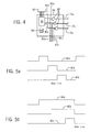
Fig. 4 is a detailed block diagram of the function module ofFig. 3 including a timing state machine and AND-gate modulator; -
Figs. 5a and 5b are timing diagrams of the outputs of the timing state machine ofFig. 4 for two modes of operation in which lamps from different beacon modules are synchronized; and -
Fig. 6 is a schematic similar to that ofFig. 3 showing an alternative configuration power converter circuit with direct power supply access. - Referring now to
Fig. 1 , astack light 10 constructed according to the present invention may be assembled of multiple interlockingbeacon modules function module 14, and abase module 16. - In one embodiment, the lowest most element of the
base module 16 may provide alower flange 19 having one ormore openings 20 for receivingmachine screws 22 or the like to fasten theflange 19 and hence thebase module 16 to asurface 24 of a machine or the like.Alternative base module 16' and 16" may provide fordifferent flanges 19' and 19" respectively (for example for mounting the vertical surfaces) or for accommodating different base constructions. - The upper surface of the
base module 16 may expose a centered electrical connectors 26 (visible inFig. 1 only onbase module 16' and 16") that may be received by a corresponding electrical connector 26 (not visible inFig. 1 ) on the lower surfaces of each of thebeacon modules 12, power-converter/function module 14 andaudio alarm module 18.Similar connectors 26 exist on the upper surface of each of the other modules thebeacon modules 12, and power-converter/function module 14 (visible inFig. 1 only on beacon module 12'). Inter-engagement of theseelectrical connectors 26 in the assembled stack light 10 provide electrical communication between each of thebase module 16beacon modules 12, power-converter/function module 14 andaudio alarm module 18 as will be described. - The upper end of the
base module 16 also provides a portion of a mechanical interlocking system in the form of radially extending tabs 28 (visible inFig. 1 only onbase module 16' and 16"). These radially extendingtabs 28 may be received by a second portion of the mechanical interlocking system in the form of twist type bayonet rings 30 rotatably affixed to the lower surfaces of each of thebeacon modules 12, and power-converter/function module 14. Such bayonet rings 30, as generally understood in the art, provide features on their inner diameter that may capture theradially extending tabs 28 against a helical flange in the manner of inter-engaging threads while providing a slight pocket at the end of rotation forming a detent that locks thetabs 28 and bayonet rings 30 into predetermined compression. - Similar radially extending
tabs 28 exist at the upper end of each of the other modules thebeacon modules 12, power-converter/function module 14 and audio alarm module 18 (visible inFig. 1 only on beacon module 12'). Inter-engagement of thesetabs 28 and bayonet rings of other modules in the assembled stack light 10 provide permit mechanical inter-connection between any of thebase module 16, thebeacon modules 12, and the power-converter/function module 14 into thestack light 10. - As assembled the
base module 16, thebeacon modules 12, the power-converter/function module 14 and theaudio alarm module 18 provide a tower extending generally upward from thebase module 16 through power-converter/function module 14, then through one ormore beacon modules 12 each of which may independently controlled to display a predetermined color illumination. - As depicted in
Fig. 1 , the tower may be capped by aplastic dome 17 also having abayonet ring 30 but noelectrical connector 26. Alternatively, anaudio alarm module 18 operating in a manner similar to that of thebeacon modules 12 but providing an audible alarm through sound ports 21 rather than an illuminated signal may replace thefinal beacon module 12c. Like the other modules, theaudio alarm module 18 may include abayonet ring 30 on its lower end for attachment to a lower module, and anelectrical connector 26 on its lower surface for electrical interconnection to an earlier lower module. Desirably, theaudio alarm module 18 may have a dome top without aconnector 26 ortabs 28 on its top surface for attachment to later modules, thereby providing a finished appearance to the top of the tower. - Referring now to
Fig. 2 ,base module 16 may provide ahousing 32, for example, constructed of electrically insulating and opaque thermoplastic. Thehousing 32 may provide a cylindrical periphery in diameter generally matching the diameter of corresponding housings of thebeacon modules 12, power-converter/function module 14 andaudio alarm module 18. Standard diameters forstack lights 10 include 30 mm, 40 mm, 50 mm, 60 mm, 70 mm and 100 mm. - A
terminal block 34 may be positioned within thehousing 32 of thebase module 16, for example, providing screw terminals, to receiveconductors 36 from a remote switching device as will be discussed below. Each of theconductors 36, when attached to theterminal block 34, will be routed to theelectrical connector 26a exposed at an upper surface of thebase module 16. Thiselectrical connector 26a receives a downwardly extendingconnector 26b from power-converter/function module 14 when it is connected tobase module 16.Electrical connectors - For simplicity, the
electrical connectors connectors 26 inFig. 2 ) are depicted with only four conductive inserts 42 (for example, conductive pins or sockets) or which may each receive aseparate conductor 36. As is understood in the art, each conductive insert 40 provides an electrically independent conductive paths within matingelectrical connectors 26. - As noted, the upper edge of the
base module 16 provides for radially extendingtabs 28 that may be received by abayonet ring 30 rotatably attached to the bottom of power-converter/function module 14. In this way thebase module 16 may be electrically and mechanically attached to the power-converter/functional module 14 withconnectors ring seal 44 may be provided at the junction between the upper surface ofbase module 16 and the lower surface of power-converter/function module 14 to reduce the ingress of environmental contamination when the two are connected. - Referring still to
Fig. 2 , power-converter/function module 14 may provide for aopaque housing 48 supporting at itsupper surface connector 26c being substantiallyidentical connector 26a and exposed to receive aconnector 26d whenbeacon module 12a is attached to the upper surface of the power-converter/function module 14. As described above this connection may be by means of radially extendingtabs 28 at the upper edge of power-converter/function module 14 received by a correspondingbayonet ring 30 ofbeacon module 12a. - As will be discussed in greater detail below, power-converter/
function module 14 includes power converter/function circuitry 56 that receives electrical power fromconnector 26b to convert this electrical power into a backbone voltage for use with thelater beacon modules 12 andaudio alarm module 18. In thisway beacon modules 12 andaudio alarm modules 18 having common voltage parameters (e.g. the same voltage and the same voltage mode of either AC or DC) can be used withstack lights 10 receiving any operating voltage. Power converter/function circuitry 56 further provides for the ability to impose modulation functions such as lamp flashing or module sequencing on thelater beacon modules 12 andaudio alarm module 18 by modulating the power received by those modules. This eliminates the need for those modules to each include circuitry for modulation functions. - In various configurations that will be discussed below, the power converter/
function circuitry 56 will receive operating electrical power and multiple signal lines throughelectrical connector 26b as derived fromconductors 36. From this, the power converter/function circuitry 56 establishes a backbone ground reference on "common"conductor 68 and multiple signal voltages for control ofbeacon modules 12 oraudio alarm module 18 onconductors 75a-75c (typically up to seven conductors although only three are shown for clarity in this example). Thecommon conductor 68 andsignal conductors 75 are connected toelectrical connector 26c, for example, as depicted in right to left order ofsignal conductors common conductor 68. - Referring still the
Fig. 2 ,connector 26d insubsequent beacon module 12b, may connect toconnector 26c and may be attached, for example, to a printedcircuit board 60 carrying on it multiple light emitting diodes (LEDs) 62. As shown,LEDs 62 are connected betweencommon conductor 68 andsignal conductor 75a occupying the extreme left and right positions of theconnector 26d. Accordingly power onsignal conductor 75a will energize theLEDs 62 ofbeacon module 12b so that the light may be viewed throughtransparent housing 63. Thehousing 63 may have a tint to provide a desired light color and/or theLEDs 62 may be selected for a desired color. - Although the
LEDs 62 are shown connected in parallel, series connections are also possible. Current sharing resistances for eachLED 62 have been omitted for clarity. - The upper edge of the
circuit board 60 may communicate withconnector 26e being identical toconnector circuit board 60 providecommon conductor 68 join an identical location ofconnectors Fig. 1 ).Signal conductor 75a used to control theLEDs 62 ofbeacon module 12a does not pass toconnector 26e, however, and signalconductors signal conductor 75b is now at the rightmost conductive insert 42 ofconnector 26e. - It will be understood then that
beacon module 12b being constructed of electrically and mechanically identical tobeacon module 12a may then be attached tobeacon module 12a in the same way thatbeacon module 12a was attach the power-converter/function module 14 and thatsignal conductor 54b will now be connected to itsLEDs 62. - The system illustrated for
beacon module 12a andbeacon module 12b may be continued tobeacon module 12c (not depicted inFig. 2 ) so thatsignal conductors third beacon modules 12 according to their order in the stack and in a manner indifferent to theexact beacon module 12 and without the need for adjustment of the internal wiring of thebeacon modules 12a or the setting of internal addresses or the like. The number of conductive inserts 42 in theconnector 26 andsignal conductors 75 determine the limit of the number ofmodules 12 may be stacked in this manner. - Referring now to
Fig. 3 , in a first wiring mode of thestack light 10,conductors 36 received by thebase module 16 do not provide to thebase module 16 direct connections to anexternal power supply 67 that provides the operating voltage of thestack light 10. Thisexternal power supply 67 is normally provided by a customer and may vary in voltage between 12 and 240 V (e.g. 12 V 24 V 120 V 240 V) and may be either AC or DC voltage (termed herein the power supply "mode"). In this wiring mode, thebase module 16 receives only a power supply common 52 and multiple switchedsignal lines 54a-54c representing power from theexternal power supply 67 only after it has been switched byexternal switch system 64. Theexternal switch system 64 may be, for example, relays or programmable logic controller I/O module referenced through apower supply 67 to the common 52. - In this embodiment, the power power-converter/
function module 14 taps thesignal conductors 54 to obtain power for its operation when it least onesignal conductor 54 is active. This may be done by attaching afull wave rectifier 66 between each thesignal conductors 54 and a common DCbus input line 71. Eachfull wave rectifier 66 is configured to steer either DC or AC current is applied to thesignal conductors 54 independently from any of thesignal conductors 54 to afilter capacitor 70 reference to a backbone common 68 while preventing crosstalk betweensignal conductors 54. - The
filter capacitor 70 is made therefore provide a source of DC voltage regardless of whether AC or DC voltage is provided by thesupply 67 for any time abeacon module 12 is to be activated. The effective filter time constant provided bycapacitor 70 is chosen to prevent the imposition of any meaningful delay in the generation necessary power once a signal present on anyone of thesignal conductors 54. Nevertheless, voltage of the power oncapacitor 70 will vary substantially according to the operating voltage of thepower supply 67. Accordingly the voltage on thecapacitor 70 may then be provided to avoltage regulator 72 uniformly converting that voltage to a least common denominator voltage (e.g. 12 VDC) oflocal backbone power 74. Thevoltage regulator 72 may be of any design including, for example, a switched mode regulator is well known in the art. By using a boost mode converter, the voltage of thelocal backbone power 74 may be in fact higher than 12 V by allowing 12 V power supply voltages ofpower supply 67 to be boosted appropriately. - The
backbone power 74 and backbone common 68 provide power to themodulation function circuit 58 as will be described below in defines the voltage level of theactive signal conductors 75 connecting to thebeacon modules 12. - As well as scavenging power from the
signal conductors 54, the power-converter/function module 14 also extracts the information content on thesignal conductors 54 by passing them through optoisolators 78 (one for each conductor 54) which isolate the operating voltage of power supply 67 (in common 52) from the backbone power 74 (and backbone common 68) optically isolatedelectrical signals conductors modulation function circuit 58 which may modulate those signals when present according to a desired pattern set by user for example, through adip switch 82 providing signals tomodulation function circuit 58. - Referring now momentarily to
Fig. 4 ,modulation function circuit 58 may implemented in a variety of different ways including a microcontroller, programmable gate array or discrete logical circuitry and generally includes amodulation clock 84, for example, providing a base modulation frequency. Themodulation clock 84 may for example be a conventional RC oscillator and divider circuit to provide a modulation frequency of 1 Hz. The output of the modulation clock is then received by programmabletiming state machine 86 whose particular programming (and hence the modulation pattern) is set by switches 82. In one example, threeoutputs beacon modules clock 84. Each of these outputs may be received by an ANDgate 88 whose other input is one of thesignals 80a-80c output from theoptoisolators 78 indicating the state of activation of thesignal conductors 54. This modulation pattern would provide synchronized flashing of anyactive beacon modules 12. In this case, the modulation pattern would be synchronized and identical amongbeacon modules 12. - Another modulation provided by
switches 82 may provide for steady high state output on each of the foursignals 80a-80c of thetiming state machine 86 essentially providing no function blinking of thebeacon modules 12 when they are activated. It will be understood that some settings of theswitches 82, may likewise provide modulation on only some of thesignals 80a-80c so that selected beacons may be modulated and other beacons not modulated. Different modulation patterns (for example frequencies) may be applied to different of thesignals 80a-80c. - Alternatively as shown in
Fig. 5a , theoutput signals 80a-80c of thetiming state machine 86 may alternately turn high in a round-robin "marquee" pattern so that whenmultiple beacon modules 12 are activated their illumination expresses an animation, for example, of an upwardly rising single point of illumination that passes successively through each colored beacon. - In contrast, as shown in
Fig. 5b , a "stacked" pattern may be implemented in which, for example, an upwardly rising animation is generated but with the lowermost beacon remaining on as successively higher beacons are illuminated until all are ultimately illuminated and then extinguished together and this pattern repeated. - In all of these examples, the flashing of
different beacon modules 12 is synchronized in a way that is difficult when the timing circuitry for flashing is localized in the individual beacons themselves. This latter modulation provides modulation patterns that are also synchronized but are not identical. Another similar synchronized but different set of modulation patterns might provide different frequencies for eachbeacon module 12 but are nevertheless phase synchronized. - Referring now to
Fig. 6 , it will be appreciated that the present invention may also work with a dedicatedpower supply line 90 from theexternal power supply 67, for example, introduced through a separate screw terminal so that thebase module 16 has direct access to constant electrical power through power supply common 52 andpower supply line 90. In this case, power may be directed from this power supply line to a singlefull wave rectifier 66 providing current tocapacitor 70. - It will be appreciated that the
LEDs 62 may be replaced with incandescent lamps according to well-understood techniques. - Certain terminology is used herein for purposes of reference only, and thus is not intended to be limiting. For example, terms such as "upper", "lower", "above", and "below" refer to directions in the drawings to which reference is made. Terms such as "front", "back", "rear", "bottom" and "side", describe the orientation of portions of the component within a consistent but arbitrary frame of reference which is made clear by reference to the text and the associated drawings describing the component under discussion. Such terminology may include the words specifically mentioned above, derivatives thereof, and words of similar import. Similarly, the terms "first", "second" and other such numerical terms referring to structures do not imply a sequence or order unless clearly indicated by the context.
- When introducing elements or features of the present disclosure and the exemplary embodiments, the articles "a", "an", "the" and "said" are intended to mean that there are one or more of such elements or features. The terms "comprising", "including" and "having" are intended to be inclusive and mean that there may be additional elements or features other than those specifically noted. It is further to be understood that the method steps, processes, and operations described herein are not to be construed as necessarily requiring their performance in the particular order discussed or illustrated, unless specifically identified as an order of performance. It is also to be understood that additional or alternative steps may be employed.
- It is specifically intended that the present invention not be limited to the embodiments and illustrations contained herein and the claims should be understood to include modified forms of those embodiments including portions of the embodiments and combinations of elements of different embodiments as come within the scope of the following claims. All of the publications described herein, including patents and non-patent publications, are hereby incorporated herein by reference in their entireties.
- It is specifically intended that the present invention not be limited to the embodiments and illustrations contained herein and the claims should be understood to include modified forms of those embodiments, including portions of the embodiments and combinations of elements of different embodiments as come within the scope of the following claims.
- The following is a list of further preferred embodiments of the invention:
- Embodiment 1. A function generator for use in a stack light of the type providing a set of beacon modules interlocking to each other and to a base unit by means of interlocking mechanical connectors and interfitting electrical connectors positioned at a top and bottom of each beacon module and at a top of the base unit together allowing multiple beacon modules and one base to be mechanically and electrically assembled into a tower with electrical communication between the base and each beacon module, the function generator comprising:
- a housing;
- first and second mechanical connectors positioned at a top and bottom of the housing adapted to releasably interlock with corresponding mechanical connectors of beacon modules and a base;
- first and second electrical connectors positioned at a top and bottom of the housing adapted to releasably interface with corresponding electrical connectors of beacon modules and a base; and
- a function generation circuit positioned within the housing and receiving electrical power from the second electrical connector to generate a time-modulation signal to provide time-modulated electrical power to the first electrical connector based on that time-modulated signal.
- Embodiment 2. The function generator of embodiment 1 further including an oscillator providing a time reference for the time-modulation signal.
- Embodiment 3. The function generator of embodiment 2 further including a switch communicating with the function generator circuit to change the time-modulated signal.
- Embodiment 4. The function generator of embodiment 3 wherein the time-modulated electrical power is provided to multiple different conductors of the first electrical connector adapted to communicate with different beacon modules and wherein the switch selects which of the different electrical connectors receives modulated electrical power based on the time-modulated signal.
- Embodiment 5. The function generator of embodiment 4 wherein the time-modulation signal provides synchronized modulation to the different conductors of the first electrical connector.
- Embodiment 6. The function generator of embodiment 5 wherein the time-modulation signal provides synchronized different modulation to the different conductors of the first electrical connector.
- Embodiment 7. The function generator of embodiment 1 wherein the housing further includes a power conversion circuit positioned within the housing and receiving electrical power from the second electrical connector having a parameter of at least one of voltage and mode to provide converted power to the function generator circuit for generation of the time-modulated electrical power.
- Embodiment 8. The function generator of embodiment 1 wherein the first and second electrical connectors are of a same connector type such as would permit inter-engagement of the first and second electrical connectors and wherein the first and second mechanical connectors are of a same connector type such as would permit inter-engagement of the first and second mechanical connectors.
- Embodiment 9. The function generator of embodiment 8 wherein the housing is substantially cylindrical and has a diameter substantially between 30 and 100 mm.
-
Embodiment 10. The function generator of embodiment 9 wherein the housing is substantially opaque and electrically insulating. - Embodiment 11. The power converter of embodiment 1 further including a power conversion circuit receiving signal lines from the second electrical connector and providing a source of electrical power derived from the signal lines to the function circuitry of the power conversion circuit, the function circuitry further modulating power on at least one signal line provided to the first electrical connector.
-
Embodiment 12. A stack light comprising:- a set of interconnected beacon modules, function generation module and base,
- wherein the interconnected beacon modules each provide;
- (a) a transparent beacon light housing;
- (b) first and second mechanical connectors positioned at a top and bottom of the beacon light housing releasably interlocked with corresponding mechanical connectors of corresponding beacon modules or the function generation module;
- (c) first and second electrical connectors positioned at a top and bottom of the beacon light housing releasably interfaced with corresponding electrical connectors of beacon modules or the function generation module; and
- (d) a lamp held within the housing and communicating with a connector element of the second electrical connector;
- wherein the function generation module provides:
- (a) a generator housing;
- (b) first and second mechanical connectors positioned at a top and bottom of the generator housing, the first mechanical connector releasably interlocking with a corresponding mechanical connector of a given beacon module and the second mechanical connector releasably interlocking with a corresponding mechanical connector of the base;
- (c) first and second electrical connectors positioned at a top and bottom of the generator housing, the first electrical connector releasably interfacing with a corresponding electrical connector of the given beacon module and the second electrical connector releasably interfacing with a corresponding electrical connector of the base; and
- (d) a function generation circuit positioned within the generator housing and receiving electrical power from the second electrical connector to generate a time-modulation signal to provide time-modulated electrical power to the first electrical connector based on that time-modulated signal;
- wherein the base provides:
- (a) a base housing
- (b) a first mechanical connector releasably interlocking with the second mechanical connector of the function generation module;
- (c) a first electrical connector releasably interfacing with the second electrical connector of the function generation module;
- (d) a terminal block electrically communicating with the first electrical connector; and
- (e) a mounting flange providing openings for receiving machine screws to attach the mounting flange to a surface.
- Embodiment 13. The stack light of
embodiment 12 wherein the first and second electrical connectors of each beacon module are interconnected to provide an identical relative shifting of locations within each connector of the signal passing through the connector to route given signals to given beacon modules depending on a relative location of the beacon module in a stack with other beacon modules. -
Embodiment 14. The stack light ofembodiment 12 wherein the electrical connectors and mechanical connectors of each of different of the beacon modules, the function generation module, and the base are electrically and mechanically inter-operable with others of the beacon modules, the function generation module, and the base. - Embodiment 15. The stack light of
embodiment 12 wherein a height of the function generation module between the first and second mechanical connectors is less than two-thirds of a height of a beacon module between the first and second mechanical connectors. -
Embodiment 16. The stack light ofembodiment 12 further including an oscillator providing a time reference for the time-modulation signal. -
Embodiment 17. The stack light ofembodiment 12 further including a switch communicating with the function generator circuit to change the time-modulated signal wherein the time-modulated electrical power is provided to multiple different conductors of the first electrical connector adapted to communicate with different beacon modules and wherein the switch selects which of the different electrical connectors receive modulated electrical power based on the time-modulated signal. -
Embodiment 18. The stack light ofembodiment 17 wherein the time-modulation signal provides synchronized modulation to the different of the first electrical connector. -
Embodiment 19. The function stack light ofembodiment 18 wherein the time-modulation signal provides synchronized different modulation to the different conductors of the first electrical connector.
| Part No. | |
| 10 | |
| 12 | |
| 14 | Power converter/ |
| 16 | |
| 17 | |
| 18 | |
| 19 | Flange |
| 21 | |
| 22 | |
| 24 | |
| 26 | |
| 28 | |
| 30 | |
| 32 | |
| 34 | |
| 36 | Conductor |
| 40 | Conductive insert |
| 42 | Conductive insert |
| 44 | O- |
| 48 | |
| 52 | Power supply common |
| 54 | |
| 56 | Power converter/ |
| 58 | |
| 60 | |
| 62 | |
| 63 | |
| 64 | |
| 66 | |
| 67 | |
| 68 | |
| 70 | |
| 71 | |
| 72 | |
| 74 | |
| 75 | |
| 78 | |
| 80 | |
| 82 | |
| 84 | Clock |
| 85 | |
| 86 | |
| 88 | |
| 90 | Power supply line |
Claims (11)
- A function generator for use in a stack light of the type providing a set of beacon modules interlocking to each other and to a base unit by means of interlocking mechanical connectors and interfitting electrical connectors positioned at a top and bottom of each beacon module and at a top of the base unit together allowing multiple beacon modules and one base to be mechanically and electrically assembled into a tower with electrical communication between the base and each beacon module, the function generator comprising:a housing;first and second mechanical connectors positioned at a top and bottom of the housing adapted to releasably interlock with corresponding mechanical connectors of beacon modules and a base;first and second electrical connectors positioned at a top and bottom of the housing adapted to releasably interface with corresponding electrical connectors of beacon modules and a base; anda function generation circuit positioned within the housing and receiving electrical power from the second electrical connector to generate a time-modulation signal to provide time-modulated electrical power to the first electrical connector based on that time-modulated signal.
- The function generator of claim 1 further including an oscillator providing a time reference for the time-modulation signal.
- The function generator of claim 2 further including a switch communicating with the function generator circuit to change the time-modulated signal.
- The function generator of claim 3 wherein the time-modulated electrical power is provided to multiple different conductors of the first electrical connector adapted to communicate with different beacon modules and wherein the switch selects which of the different electrical connectors receives modulated electrical power based on the time-modulated signal.
- The function generator of claim 4 wherein the time-modulation signal provides synchronized modulation to the different conductors of the first electrical connector.
- The function generator of claim 5 wherein the time-modulation signal provides synchronized different modulation to the different conductors of the first electrical connector.
- The function generator of claim 1 wherein the housing further includes a power conversion circuit positioned within the housing and receiving electrical power from the second electrical connector having a parameter of at least one of voltage and mode to provide converted power to the function generator circuit for generation of the time-modulated electrical power.
- The function generator of claim 1 wherein the first and second electrical connectors are of a same connector type such as would permit inter-engagement of the first and second electrical connectors and wherein the first and second mechanical connectors are of a same connector type such as would permit inter-engagement of the first and second mechanical connectors.
- The function generator of claim 8 wherein the housing is substantially cylindrical and has a diameter substantially between 30 and 100 mm.
- The function generator of claim 9 wherein the housing is substantially opaque and electrically insulating.
- The function generator of claim 1 further including a power conversion circuit receiving signal lines from the second electrical connector and providing a source of electrical power derived from the signal lines to the function circuitry of the power conversion circuit, the function circuitry further modulating power on at least one signal line provided to the first electrical connector.
Applications Claiming Priority (1)
| Application Number | Priority Date | Filing Date | Title |
|---|---|---|---|
| US14/153,561 US20150198316A1 (en) | 2014-01-13 | 2014-01-13 | Stack Light with Modular Function Generator |
Publications (2)
| Publication Number | Publication Date |
|---|---|
| EP2911476A1 true EP2911476A1 (en) | 2015-08-26 |
| EP2911476B1 EP2911476B1 (en) | 2019-08-14 |
Family
ID=52440538
Family Applications (1)
| Application Number | Title | Priority Date | Filing Date |
|---|---|---|---|
| EP15150232.5A Active EP2911476B1 (en) | 2014-01-13 | 2015-01-07 | Stack light with modular function generator |
Country Status (2)
| Country | Link |
|---|---|
| US (1) | US20150198316A1 (en) |
| EP (1) | EP2911476B1 (en) |
Cited By (2)
| Publication number | Priority date | Publication date | Assignee | Title |
|---|---|---|---|---|
| WO2017115428A1 (en) * | 2015-12-28 | 2017-07-06 | 株式会社パトライト | Signaling light stacking unit and signaling light |
| JP2018046030A (en) * | 2017-12-27 | 2018-03-22 | 株式会社パトライト | Lamination unit for signal display lamp and signal display lamp |
Families Citing this family (1)
| Publication number | Priority date | Publication date | Assignee | Title |
|---|---|---|---|---|
| GB2577757A (en) * | 2018-10-06 | 2020-04-08 | Eaton Intelligent Power Ltd | A stack light for indicating a status of an apparatus to be monitored |
Citations (4)
| Publication number | Priority date | Publication date | Assignee | Title |
|---|---|---|---|---|
| DE19513983A1 (en) * | 1994-04-15 | 1995-10-19 | Werma Signalgeraete Gmbh & Co | Optical or acoustic signalling column |
| DE10058695A1 (en) * | 2000-11-27 | 2002-05-29 | Lmg Signaltechnologie Kg | Signal column has radio module(s) connected to receiver or in form of transmitter and/or receiver; radio module can be provided for individual signal elements and is mounted in pedestal |
| US20060044814A1 (en) * | 2004-09-02 | 2006-03-02 | Patlite Corporation | Lens component, indicator unit for signal indicating light, and signal indicating light |
| EP2182776A1 (en) * | 2008-11-04 | 2010-05-05 | WERMA Holding GmbH + Co. KG | Warning light with a cap unit and at least one light unit |
Family Cites Families (7)
| Publication number | Priority date | Publication date | Assignee | Title |
|---|---|---|---|---|
| GB1557685A (en) * | 1976-02-02 | 1979-12-12 | Fairchild Camera Instr Co | Optically coupled isolator device |
| US20030030567A1 (en) * | 2001-08-13 | 2003-02-13 | Hetzel William Hieby | Flexible functionality of stack light |
| JP4134748B2 (en) * | 2003-02-21 | 2008-08-20 | 株式会社パトライト | Signal indicator unit and signal indicator |
| WO2007013003A1 (en) * | 2005-07-27 | 2007-02-01 | Philips Intellectual Property & Standards Gmbh | Lighting system and method for controlling a plurality of light sources |
| US7508141B2 (en) * | 2006-03-20 | 2009-03-24 | Wham Development Company (Hk Pshp) | Modular decorative light system |
| DE202007005495U1 (en) * | 2007-04-13 | 2007-08-30 | Werma Signaltechnik Gmbh + Co. Kg | Alarm lamp |
| US9175827B2 (en) * | 2012-05-09 | 2015-11-03 | Lee Clore | Indicator light tower technology |
-
2014
- 2014-01-13 US US14/153,561 patent/US20150198316A1/en not_active Abandoned
-
2015
- 2015-01-07 EP EP15150232.5A patent/EP2911476B1/en active Active
Patent Citations (4)
| Publication number | Priority date | Publication date | Assignee | Title |
|---|---|---|---|---|
| DE19513983A1 (en) * | 1994-04-15 | 1995-10-19 | Werma Signalgeraete Gmbh & Co | Optical or acoustic signalling column |
| DE10058695A1 (en) * | 2000-11-27 | 2002-05-29 | Lmg Signaltechnologie Kg | Signal column has radio module(s) connected to receiver or in form of transmitter and/or receiver; radio module can be provided for individual signal elements and is mounted in pedestal |
| US20060044814A1 (en) * | 2004-09-02 | 2006-03-02 | Patlite Corporation | Lens component, indicator unit for signal indicating light, and signal indicating light |
| EP2182776A1 (en) * | 2008-11-04 | 2010-05-05 | WERMA Holding GmbH + Co. KG | Warning light with a cap unit and at least one light unit |
Cited By (9)
| Publication number | Priority date | Publication date | Assignee | Title |
|---|---|---|---|---|
| WO2017115428A1 (en) * | 2015-12-28 | 2017-07-06 | 株式会社パトライト | Signaling light stacking unit and signaling light |
| CN107407463A (en) * | 2015-12-28 | 2017-11-28 | 株式会社派特莱 | Laminated units for signal indicator lamps and signal indicator lamps |
| JPWO2017115428A1 (en) * | 2015-12-28 | 2017-12-28 | 株式会社パトライト | Stacking unit for signal indicators and signal indicators |
| KR20180079226A (en) * | 2015-12-28 | 2018-07-10 | 가부시키가이샤 파토라이토 | Laminated units and signal indicators for signal indicators |
| US10047935B2 (en) | 2015-12-28 | 2018-08-14 | Patlite Corporation | Stack unit for signal indicator lamp, and signal indicator lamp |
| KR20190077589A (en) * | 2015-12-28 | 2019-07-03 | 가부시키가이샤 파토라이토 | Signaling light stacking unit and signaling light |
| TWI680443B (en) * | 2015-12-28 | 2019-12-21 | 日商派特萊股份有限公司 | Multilayer unit for signal display lamp and signal display lamp |
| CN107407463B (en) * | 2015-12-28 | 2020-07-14 | 株式会社派特莱 | Stacking unit for signal indicator light and signal indicator light |
| JP2018046030A (en) * | 2017-12-27 | 2018-03-22 | 株式会社パトライト | Lamination unit for signal display lamp and signal display lamp |
Also Published As
| Publication number | Publication date |
|---|---|
| US20150198316A1 (en) | 2015-07-16 |
| EP2911476B1 (en) | 2019-08-14 |
Similar Documents
| Publication | Publication Date | Title |
|---|---|---|
| EP2894945A2 (en) | Stack light with modular power converter | |
| US10588187B2 (en) | LED driver adapted for gang boxes | |
| US9845949B2 (en) | Modular stack light with central connectors | |
| EP1388276B1 (en) | Systems and methods for synchronizing lighting effects | |
| US6801003B2 (en) | Systems and methods for synchronizing lighting effects | |
| US8471480B2 (en) | Decorative light string having master and slave modes and master override switch | |
| US10631386B1 (en) | Multi-color flat rope light string system | |
| US10285225B2 (en) | LED lighting system | |
| US20090322250A1 (en) | Networked architectural lighting with customizable color accents | |
| US8485703B2 (en) | Aircraft cabin lighting system and kit therefor | |
| US20070127238A1 (en) | Double pole led outlet switch | |
| US20180283668A1 (en) | Modular power system for cabinets | |
| EP2911476B1 (en) | Stack light with modular function generator | |
| US10887956B2 (en) | LED lighting system | |
| US20200096177A1 (en) | Modular Luminaire | |
| EP2788675B1 (en) | Linear luminaire system, with fitting light modules | |
| US20090109708A1 (en) | Radiance lighting system and method | |
| CN113167441A (en) | Triple Multi-Tone LED Bulb with Joystick and Integrated Control Unit | |
| WO2022136167A1 (en) | Modular lighting system | |
| JP6915912B1 (en) | Ceiling lighting fixtures |
Legal Events
| Date | Code | Title | Description |
|---|---|---|---|
| PUAI | Public reference made under article 153(3) epc to a published international application that has entered the european phase |
Free format text: ORIGINAL CODE: 0009012 |
|
| AK | Designated contracting states |
Kind code of ref document: A1 Designated state(s): AL AT BE BG CH CY CZ DE DK EE ES FI FR GB GR HR HU IE IS IT LI LT LU LV MC MK MT NL NO PL PT RO RS SE SI SK SM TR |
|
| AX | Request for extension of the european patent |
Extension state: BA ME |
|
| 17P | Request for examination filed |
Effective date: 20160217 |
|
| RBV | Designated contracting states (corrected) |
Designated state(s): AL AT BE BG CH CY CZ DE DK EE ES FI FR GB GR HR HU IE IS IT LI LT LU LV MC MK MT NL NO PL PT RO RS SE SI SK SM TR |
|
| STAA | Information on the status of an ep patent application or granted ep patent |
Free format text: STATUS: EXAMINATION IS IN PROGRESS |
|
| 17Q | First examination report despatched |
Effective date: 20180817 |
|
| GRAP | Despatch of communication of intention to grant a patent |
Free format text: ORIGINAL CODE: EPIDOSNIGR1 |
|
| STAA | Information on the status of an ep patent application or granted ep patent |
Free format text: STATUS: GRANT OF PATENT IS INTENDED |
|
| INTG | Intention to grant announced |
Effective date: 20190320 |
|
| GRAS | Grant fee paid |
Free format text: ORIGINAL CODE: EPIDOSNIGR3 |
|
| GRAA | (expected) grant |
Free format text: ORIGINAL CODE: 0009210 |
|
| STAA | Information on the status of an ep patent application or granted ep patent |
Free format text: STATUS: THE PATENT HAS BEEN GRANTED |
|
| AK | Designated contracting states |
Kind code of ref document: B1 Designated state(s): AL AT BE BG CH CY CZ DE DK EE ES FI FR GB GR HR HU IE IS IT LI LT LU LV MC MK MT NL NO PL PT RO RS SE SI SK SM TR |
|
| REG | Reference to a national code |
Ref country code: GB Ref legal event code: FG4D |
|
| REG | Reference to a national code |
Ref country code: CH Ref legal event code: EP Ref country code: AT Ref legal event code: REF Ref document number: 1168580 Country of ref document: AT Kind code of ref document: T Effective date: 20190815 |
|
| REG | Reference to a national code |
Ref country code: DE Ref legal event code: R096 Ref document number: 602015035653 Country of ref document: DE |
|
| REG | Reference to a national code |
Ref country code: IE Ref legal event code: FG4D |
|
| REG | Reference to a national code |
Ref country code: DE Ref legal event code: R079 Ref document number: 602015035653 Country of ref document: DE Free format text: PREVIOUS MAIN CLASS: H05B0033080000 Ipc: H05B0045000000 |
|
| REG | Reference to a national code |
Ref country code: NL Ref legal event code: MP Effective date: 20190814 |
|
| REG | Reference to a national code |
Ref country code: LT Ref legal event code: MG4D |
|
| PG25 | Lapsed in a contracting state [announced via postgrant information from national office to epo] |
Ref country code: LT Free format text: LAPSE BECAUSE OF FAILURE TO SUBMIT A TRANSLATION OF THE DESCRIPTION OR TO PAY THE FEE WITHIN THE PRESCRIBED TIME-LIMIT Effective date: 20190814 Ref country code: NL Free format text: LAPSE BECAUSE OF FAILURE TO SUBMIT A TRANSLATION OF THE DESCRIPTION OR TO PAY THE FEE WITHIN THE PRESCRIBED TIME-LIMIT Effective date: 20190814 Ref country code: HR Free format text: LAPSE BECAUSE OF FAILURE TO SUBMIT A TRANSLATION OF THE DESCRIPTION OR TO PAY THE FEE WITHIN THE PRESCRIBED TIME-LIMIT Effective date: 20190814 Ref country code: SE Free format text: LAPSE BECAUSE OF FAILURE TO SUBMIT A TRANSLATION OF THE DESCRIPTION OR TO PAY THE FEE WITHIN THE PRESCRIBED TIME-LIMIT Effective date: 20190814 Ref country code: BG Free format text: LAPSE BECAUSE OF FAILURE TO SUBMIT A TRANSLATION OF THE DESCRIPTION OR TO PAY THE FEE WITHIN THE PRESCRIBED TIME-LIMIT Effective date: 20191114 Ref country code: FI Free format text: LAPSE BECAUSE OF FAILURE TO SUBMIT A TRANSLATION OF THE DESCRIPTION OR TO PAY THE FEE WITHIN THE PRESCRIBED TIME-LIMIT Effective date: 20190814 Ref country code: NO Free format text: LAPSE BECAUSE OF FAILURE TO SUBMIT A TRANSLATION OF THE DESCRIPTION OR TO PAY THE FEE WITHIN THE PRESCRIBED TIME-LIMIT Effective date: 20191114 Ref country code: PT Free format text: LAPSE BECAUSE OF FAILURE TO SUBMIT A TRANSLATION OF THE DESCRIPTION OR TO PAY THE FEE WITHIN THE PRESCRIBED TIME-LIMIT Effective date: 20191216 |
|
| REG | Reference to a national code |
Ref country code: AT Ref legal event code: MK05 Ref document number: 1168580 Country of ref document: AT Kind code of ref document: T Effective date: 20190814 |
|
| PG25 | Lapsed in a contracting state [announced via postgrant information from national office to epo] |
Ref country code: RS Free format text: LAPSE BECAUSE OF FAILURE TO SUBMIT A TRANSLATION OF THE DESCRIPTION OR TO PAY THE FEE WITHIN THE PRESCRIBED TIME-LIMIT Effective date: 20190814 Ref country code: IS Free format text: LAPSE BECAUSE OF FAILURE TO SUBMIT A TRANSLATION OF THE DESCRIPTION OR TO PAY THE FEE WITHIN THE PRESCRIBED TIME-LIMIT Effective date: 20191214 Ref country code: GR Free format text: LAPSE BECAUSE OF FAILURE TO SUBMIT A TRANSLATION OF THE DESCRIPTION OR TO PAY THE FEE WITHIN THE PRESCRIBED TIME-LIMIT Effective date: 20191115 Ref country code: LV Free format text: LAPSE BECAUSE OF FAILURE TO SUBMIT A TRANSLATION OF THE DESCRIPTION OR TO PAY THE FEE WITHIN THE PRESCRIBED TIME-LIMIT Effective date: 20190814 Ref country code: AL Free format text: LAPSE BECAUSE OF FAILURE TO SUBMIT A TRANSLATION OF THE DESCRIPTION OR TO PAY THE FEE WITHIN THE PRESCRIBED TIME-LIMIT Effective date: 20190814 Ref country code: ES Free format text: LAPSE BECAUSE OF FAILURE TO SUBMIT A TRANSLATION OF THE DESCRIPTION OR TO PAY THE FEE WITHIN THE PRESCRIBED TIME-LIMIT Effective date: 20190814 |
|
| PG25 | Lapsed in a contracting state [announced via postgrant information from national office to epo] |
Ref country code: TR Free format text: LAPSE BECAUSE OF FAILURE TO SUBMIT A TRANSLATION OF THE DESCRIPTION OR TO PAY THE FEE WITHIN THE PRESCRIBED TIME-LIMIT Effective date: 20190814 |
|
| PG25 | Lapsed in a contracting state [announced via postgrant information from national office to epo] |
Ref country code: DK Free format text: LAPSE BECAUSE OF FAILURE TO SUBMIT A TRANSLATION OF THE DESCRIPTION OR TO PAY THE FEE WITHIN THE PRESCRIBED TIME-LIMIT Effective date: 20190814 Ref country code: PL Free format text: LAPSE BECAUSE OF FAILURE TO SUBMIT A TRANSLATION OF THE DESCRIPTION OR TO PAY THE FEE WITHIN THE PRESCRIBED TIME-LIMIT Effective date: 20190814 Ref country code: IT Free format text: LAPSE BECAUSE OF FAILURE TO SUBMIT A TRANSLATION OF THE DESCRIPTION OR TO PAY THE FEE WITHIN THE PRESCRIBED TIME-LIMIT Effective date: 20190814 Ref country code: RO Free format text: LAPSE BECAUSE OF FAILURE TO SUBMIT A TRANSLATION OF THE DESCRIPTION OR TO PAY THE FEE WITHIN THE PRESCRIBED TIME-LIMIT Effective date: 20190814 Ref country code: EE Free format text: LAPSE BECAUSE OF FAILURE TO SUBMIT A TRANSLATION OF THE DESCRIPTION OR TO PAY THE FEE WITHIN THE PRESCRIBED TIME-LIMIT Effective date: 20190814 Ref country code: AT Free format text: LAPSE BECAUSE OF FAILURE TO SUBMIT A TRANSLATION OF THE DESCRIPTION OR TO PAY THE FEE WITHIN THE PRESCRIBED TIME-LIMIT Effective date: 20190814 |
|
| PG25 | Lapsed in a contracting state [announced via postgrant information from national office to epo] |
Ref country code: IS Free format text: LAPSE BECAUSE OF FAILURE TO SUBMIT A TRANSLATION OF THE DESCRIPTION OR TO PAY THE FEE WITHIN THE PRESCRIBED TIME-LIMIT Effective date: 20200224 Ref country code: SM Free format text: LAPSE BECAUSE OF FAILURE TO SUBMIT A TRANSLATION OF THE DESCRIPTION OR TO PAY THE FEE WITHIN THE PRESCRIBED TIME-LIMIT Effective date: 20190814 Ref country code: CZ Free format text: LAPSE BECAUSE OF FAILURE TO SUBMIT A TRANSLATION OF THE DESCRIPTION OR TO PAY THE FEE WITHIN THE PRESCRIBED TIME-LIMIT Effective date: 20190814 Ref country code: SK Free format text: LAPSE BECAUSE OF FAILURE TO SUBMIT A TRANSLATION OF THE DESCRIPTION OR TO PAY THE FEE WITHIN THE PRESCRIBED TIME-LIMIT Effective date: 20190814 |
|
| REG | Reference to a national code |
Ref country code: DE Ref legal event code: R097 Ref document number: 602015035653 Country of ref document: DE |
|
| PLBE | No opposition filed within time limit |
Free format text: ORIGINAL CODE: 0009261 |
|
| STAA | Information on the status of an ep patent application or granted ep patent |
Free format text: STATUS: NO OPPOSITION FILED WITHIN TIME LIMIT |
|
| PG2D | Information on lapse in contracting state deleted |
Ref country code: IS |
|
| 26N | No opposition filed |
Effective date: 20200603 |
|
| PG25 | Lapsed in a contracting state [announced via postgrant information from national office to epo] |
Ref country code: MC Free format text: LAPSE BECAUSE OF FAILURE TO SUBMIT A TRANSLATION OF THE DESCRIPTION OR TO PAY THE FEE WITHIN THE PRESCRIBED TIME-LIMIT Effective date: 20190814 Ref country code: SI Free format text: LAPSE BECAUSE OF FAILURE TO SUBMIT A TRANSLATION OF THE DESCRIPTION OR TO PAY THE FEE WITHIN THE PRESCRIBED TIME-LIMIT Effective date: 20190814 |
|
| REG | Reference to a national code |
Ref country code: CH Ref legal event code: PL |
|
| REG | Reference to a national code |
Ref country code: BE Ref legal event code: MM Effective date: 20200131 |
|
| PG25 | Lapsed in a contracting state [announced via postgrant information from national office to epo] |
Ref country code: LU Free format text: LAPSE BECAUSE OF NON-PAYMENT OF DUE FEES Effective date: 20200107 |
|
| PG25 | Lapsed in a contracting state [announced via postgrant information from national office to epo] |
Ref country code: BE Free format text: LAPSE BECAUSE OF NON-PAYMENT OF DUE FEES Effective date: 20200131 Ref country code: LI Free format text: LAPSE BECAUSE OF NON-PAYMENT OF DUE FEES Effective date: 20200131 Ref country code: CH Free format text: LAPSE BECAUSE OF NON-PAYMENT OF DUE FEES Effective date: 20200131 |
|
| PG25 | Lapsed in a contracting state [announced via postgrant information from national office to epo] |
Ref country code: IE Free format text: LAPSE BECAUSE OF NON-PAYMENT OF DUE FEES Effective date: 20200107 |
|
| PG25 | Lapsed in a contracting state [announced via postgrant information from national office to epo] |
Ref country code: MT Free format text: LAPSE BECAUSE OF FAILURE TO SUBMIT A TRANSLATION OF THE DESCRIPTION OR TO PAY THE FEE WITHIN THE PRESCRIBED TIME-LIMIT Effective date: 20190814 Ref country code: CY Free format text: LAPSE BECAUSE OF FAILURE TO SUBMIT A TRANSLATION OF THE DESCRIPTION OR TO PAY THE FEE WITHIN THE PRESCRIBED TIME-LIMIT Effective date: 20190814 |
|
| PG25 | Lapsed in a contracting state [announced via postgrant information from national office to epo] |
Ref country code: MK Free format text: LAPSE BECAUSE OF FAILURE TO SUBMIT A TRANSLATION OF THE DESCRIPTION OR TO PAY THE FEE WITHIN THE PRESCRIBED TIME-LIMIT Effective date: 20190814 |
|
| PGFP | Annual fee paid to national office [announced via postgrant information from national office to epo] |
Ref country code: GB Payment date: 20221221 Year of fee payment: 9 Ref country code: FR Payment date: 20221220 Year of fee payment: 9 |
|
| PGFP | Annual fee paid to national office [announced via postgrant information from national office to epo] |
Ref country code: DE Payment date: 20221220 Year of fee payment: 9 |
|
| P01 | Opt-out of the competence of the unified patent court (upc) registered |
Effective date: 20230404 |
|
| REG | Reference to a national code |
Ref country code: DE Ref legal event code: R119 Ref document number: 602015035653 Country of ref document: DE |
|
| GBPC | Gb: european patent ceased through non-payment of renewal fee |
Effective date: 20240107 |
|
| PG25 | Lapsed in a contracting state [announced via postgrant information from national office to epo] |
Ref country code: DE Free format text: LAPSE BECAUSE OF NON-PAYMENT OF DUE FEES Effective date: 20240801 |
|
| PG25 | Lapsed in a contracting state [announced via postgrant information from national office to epo] |
Ref country code: GB Free format text: LAPSE BECAUSE OF NON-PAYMENT OF DUE FEES Effective date: 20240107 |
|
| PG25 | Lapsed in a contracting state [announced via postgrant information from national office to epo] |
Ref country code: FR Free format text: LAPSE BECAUSE OF NON-PAYMENT OF DUE FEES Effective date: 20240131 |
|
| PG25 | Lapsed in a contracting state [announced via postgrant information from national office to epo] |
Ref country code: GB Free format text: LAPSE BECAUSE OF NON-PAYMENT OF DUE FEES Effective date: 20240107 Ref country code: FR Free format text: LAPSE BECAUSE OF NON-PAYMENT OF DUE FEES Effective date: 20240131 Ref country code: DE Free format text: LAPSE BECAUSE OF NON-PAYMENT OF DUE FEES Effective date: 20240801 |