EP2911464B1 - Wireless surveillance camera system and wireless surveillance camera device - Google Patents
Wireless surveillance camera system and wireless surveillance camera device Download PDFInfo
- Publication number
- EP2911464B1 EP2911464B1 EP13848017.3A EP13848017A EP2911464B1 EP 2911464 B1 EP2911464 B1 EP 2911464B1 EP 13848017 A EP13848017 A EP 13848017A EP 2911464 B1 EP2911464 B1 EP 2911464B1
- Authority
- EP
- European Patent Office
- Prior art keywords
- wireless
- transmission
- polling
- surveillance camera
- camera device
- Prior art date
- Legal status (The legal status is an assumption and is not a legal conclusion. Google has not performed a legal analysis and makes no representation as to the accuracy of the status listed.)
- Not-in-force
Links
Images



Classifications
-
- H—ELECTRICITY
- H04—ELECTRIC COMMUNICATION TECHNIQUE
- H04W—WIRELESS COMMUNICATION NETWORKS
- H04W28/00—Network traffic management; Network resource management
- H04W28/02—Traffic management, e.g. flow control or congestion control
- H04W28/0205—Traffic management, e.g. flow control or congestion control at the air interface
-
- H—ELECTRICITY
- H04—ELECTRIC COMMUNICATION TECHNIQUE
- H04N—PICTORIAL COMMUNICATION, e.g. TELEVISION
- H04N7/00—Television systems
- H04N7/18—Closed-circuit television [CCTV] systems, i.e. systems in which the video signal is not broadcast
- H04N7/181—Closed-circuit television [CCTV] systems, i.e. systems in which the video signal is not broadcast for receiving images from a plurality of remote sources
-
- G—PHYSICS
- G08—SIGNALLING
- G08B—SIGNALLING SYSTEMS, e.g. PERSONAL CALLING SYSTEMS; ORDER TELEGRAPHS; ALARM SYSTEMS
- G08B13/00—Burglar, theft or intruder alarms
- G08B13/18—Actuation by interference with heat, light, or radiation of shorter wavelength; Actuation by intruding sources of heat, light, or radiation of shorter wavelength
- G08B13/189—Actuation by interference with heat, light, or radiation of shorter wavelength; Actuation by intruding sources of heat, light, or radiation of shorter wavelength using passive radiation detection systems
- G08B13/194—Actuation by interference with heat, light, or radiation of shorter wavelength; Actuation by intruding sources of heat, light, or radiation of shorter wavelength using passive radiation detection systems using image scanning and comparing systems
- G08B13/196—Actuation by interference with heat, light, or radiation of shorter wavelength; Actuation by intruding sources of heat, light, or radiation of shorter wavelength using passive radiation detection systems using image scanning and comparing systems using television cameras
- G08B13/19678—User interface
- G08B13/19689—Remote control of cameras, e.g. remote orientation or image zooming control for a PTZ camera
-
- H—ELECTRICITY
- H04—ELECTRIC COMMUNICATION TECHNIQUE
- H04L—TRANSMISSION OF DIGITAL INFORMATION, e.g. TELEGRAPHIC COMMUNICATION
- H04L65/00—Network arrangements, protocols or services for supporting real-time applications in data packet communication
- H04L65/1066—Session management
-
- H—ELECTRICITY
- H04—ELECTRIC COMMUNICATION TECHNIQUE
- H04L—TRANSMISSION OF DIGITAL INFORMATION, e.g. TELEGRAPHIC COMMUNICATION
- H04L65/00—Network arrangements, protocols or services for supporting real-time applications in data packet communication
- H04L65/80—Responding to QoS
-
- H—ELECTRICITY
- H04—ELECTRIC COMMUNICATION TECHNIQUE
- H04N—PICTORIAL COMMUNICATION, e.g. TELEVISION
- H04N7/00—Television systems
- H04N7/18—Closed-circuit television [CCTV] systems, i.e. systems in which the video signal is not broadcast
- H04N7/183—Closed-circuit television [CCTV] systems, i.e. systems in which the video signal is not broadcast for receiving images from a single remote source
- H04N7/185—Closed-circuit television [CCTV] systems, i.e. systems in which the video signal is not broadcast for receiving images from a single remote source from a mobile camera, e.g. for remote control
-
- H—ELECTRICITY
- H04—ELECTRIC COMMUNICATION TECHNIQUE
- H04W—WIRELESS COMMUNICATION NETWORKS
- H04W72/00—Local resource management
- H04W72/12—Wireless traffic scheduling
- H04W72/1263—Mapping of traffic onto schedule, e.g. scheduled allocation or multiplexing of flows
- H04W72/1273—Mapping of traffic onto schedule, e.g. scheduled allocation or multiplexing of flows of downlink data flows
-
- H—ELECTRICITY
- H04—ELECTRIC COMMUNICATION TECHNIQUE
- H04W—WIRELESS COMMUNICATION NETWORKS
- H04W74/00—Wireless channel access
- H04W74/02—Hybrid access
-
- H—ELECTRICITY
- H04—ELECTRIC COMMUNICATION TECHNIQUE
- H04W—WIRELESS COMMUNICATION NETWORKS
- H04W74/00—Wireless channel access
- H04W74/04—Scheduled access
- H04W74/06—Scheduled access using polling
-
- H—ELECTRICITY
- H04—ELECTRIC COMMUNICATION TECHNIQUE
- H04W—WIRELESS COMMUNICATION NETWORKS
- H04W74/00—Wireless channel access
- H04W74/08—Non-scheduled access, e.g. ALOHA
- H04W74/0808—Non-scheduled access, e.g. ALOHA using carrier sensing, e.g. carrier sense multiple access [CSMA]
Definitions
- the present invention relates to a surveillance camera system and a surveillance camera device with a wireless communication function.
- Patent Literature 1 and Patent Literature 2 There are a large number of conventional techniques in which a wireless communication technique is applied to a surveillance camera system (for example, Patent Literature 1 and Patent Literature 2).
- a wireless communication technique for example, Patent Literature 1 and Patent Literature 2.
- systems for transmitting a video taken by a surveillance camera through a wireless LAN are disclosed in Patent Literature 1 and 2.
- a system with a QoS (Quality of Service) function in a wireless LAN system using extended MAC (Media Access Control) of IEEE 802.11e is disclosed in Patent Literature 3.
- DCF Distributed Coordination Access
- PCF Point Coordination Channel Access
- EDCA Enhanced Distributed Channel Access
- HCCA Hybrid coordinated function Controlled Channel Access
- the DCF and the EDCA are systems based on CSMA (Carrier Sense Multiple Access), and contention-based access means is provided to a tenninal.
- the PCF and the HC-CA are access methods using a polling system, and contention-free access means is provided to a tenninal.
- a reference scheduling method using the HCCA is also disclosed in the IEEE 802.11e standard.
- US 2009/189981 A1 discloses a wireless video transmission system using polling-based and contention-based transmission in different transmission channels.
- WO 03/094451 A1 discloses another related data packet transmission system employing data control units for polling-based and priority-based packet transmission.
- the taken video and/or voice data needs to be transmitted in real time without a delay, at a certain throughput (that is, QoS needs to be secured in the transmission).
- QoS Quality of Service
- An example of a wireless technique for providing the QoS includes a method of using the EDCA or the HCCA defined in the IEEE 802.11e standard.
- the following problems may occur in applying the EDCA or the HCCA to the surveillance camera system.
- the surveillance camera system communication of configuration information, control infonnation, and the like is necessary at the same time as the exchange of video and/or voice data.
- the configuration information and the like are communicated at the same time by the same communication system as that of the video and/or voice data
- the communication band of the video and/or voice data may be tightened by the configuration information and the like, and this may increase the transmission delay of the video and/or voice data.
- the system of communicating the configuration information and the like at the same time by the same communication system as that of the video and/or voice data may also increase the communication delay of data (for example, configuration information and control signal) other than the video or voice data.
- the present invention has been made in view of the technical problems, and the present invention provides a wireless surveillance camera system that can efficiently communicate configuration information of a camera device and a wireless device at the same time while ensuring a certain band and low-delay communication of video and/or voice data.
- An invention as a first solution is a wireless surveillance camera system including: (1) at least one wireless surveillance camera device including a camera device and a wireless device; and (2) a wireless base station that receives a wireless signal transmitted from the wireless surveillance camera device, and the wireless surveillance camera device and the wireless base station have the following features.
- the following function is added to the scheduling controller of the wireless base station in the wireless surveillance camera system according to the first solution. Specifically, added is a function of dividing one service interval into an exhaustive polling phase, a selective polling phase, and a carrier sense phase; scheduling polling for a registered wireless surveillance camera device at least once in the exhaustive polling phase; repeatedly scheduling polling for a wireless surveillance camera, for which a return frame for the polling is not normally received in the service interval, in the selective polling phase; and scheduling an access opportunity in the carrier sense system in the carrier sense phase without transmitting polling.
- the following function is added to the wireless surveillance camera device in the wireless surveillance camera system according to the first solution. Specifically, added is a function of counting communication parameters (the number of polling receptions, the number of ACK receptions, and the like) indicating a state of communication with the wireless base station and generating; and transmitting a packet so as to forward the communication parameters to the second transmission queue associated with the carrier sense system.
- the number of elements or the like is not limited to the specific number, and the number may be greater or smaller than the specific number, unless otherwise particularly specified or when the number is clearly limited to the specific number in principle.
- the constituent elements are not always essential, unless otherwise particularly specified or when the constituent elements are clearly essential in principle.
- part or all of the configurations, functions, processing units, processing means, and the like may be realized by, for example, integrated circuits or other hardware.
- a processor may interpret and execute programs for realizing functions to realize the configurations, the functions, and the like. More specifically, the configurations, the functions, and the like may be realized by software.
- Information of the programs, tables, files, and the like for realizing the functions can be stored in a memory, a memory device such as a hard disk and an SSD (Solid State Drive), or a storage medium such as an IC card, an SD card, and a DVD.
- control lines and information lines considered necessary for the description are illustrated, and not all control lines and information lines necessary for the product are illustrated. It can be considered that in reality, almost all of the components are mutually connected.
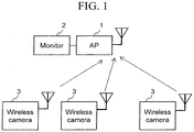
- Fig. 1 is a configuration example of a wireless surveillance camera system according to a first embodiment.
- the wireless surveillance camera system shown in Fig. 1 includes a wireless base station (AP) 1, a monitor device (Monitor) 2, and wireless camera devices (Wireless Cameras) 3.
- AP wireless base station
- Monitoring monitor device
- Wireless Cameras wireless camera devices
- a plurality of wireless camera devices 3 communicate with the wireless base station 1.
- the monitor device 2 receives and displays video and/or voice data transmitted from the wireless camera devices 3.
- the monitor device 2 also provides a user interface function and a communication function for acquiring, configuring, and controlling configuration information of the wireless camera devices 3 as necessary.
- the configuration information includes, for example, configuration information of video parameters, configuration information of wireless parameters, and the like.
- the configuration information of video parameters includes, for example, (1) codec information (type of codec (H.264, MPEG, or M-JPEG), image quality (compressibility), resolution, coded bit rate, and frame rate), (2) camera configuration information (whether to perform backlight correction, photometric area, whether to perform gamma correction, color level adjustment, black level adjustment, contour correction, zoom magnification, direction of camera, and the like), (3) voice information (codec, bit rate, reception timeout, microphone input level, line output level, and input mute level), and (4) other information (date information and NTP synchronization setting).
- the configuration information of wireless parameters includes, for example, (1) network basic configuration information (IP address, DNS (Dynamic Name Resolution) information, port information, MTU (Maximum Transmission Unit) size, retransmission timeout time, ARP (Address Resolution Protocol) transmission time, and IP filter information), (2) user authentication information (ON/OFF of user authentication function and user configuration information (user name, password, and authority)), and (3) wireless configuration information (encryption key configuration, mode switching, transmission output change, carrier sense level change, and the like).
- IP address IP address
- DNS Dynamic Name Resolution
- MTU Maximum Transmission Unit
- ARP Address Resolution Protocol
- wireless configuration information encryption key configuration, mode switching, transmission output change, carrier sense level change, and the like.
- a memory device that stores video data for example, hard disk device or storage device
- a computer for configuration may be connected to the monitor device 2.
- Fig. 2 shows a configuration example of the wireless camera device 3
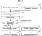
- Fig. 3 shows a data transmission procedure executed by the wireless camera device 3.
- the wireless camera device 3 includes a camera device (Camera device) 101, a processor (Processor) 102, a wireless device (Wireless device) 103, and a main memory device (Memory) 104.
- the camera device 101 according to the present embodiment also includes an imaging optical system not shown, an imaging element (for example, CMOS sensor), a microphone not shown, a function of outputting video data of images taken by the imaging element, and a function of outputting voice data of sound collected by the microphone.
- Video or voice data acquired by the camera device 101 is forwarded to the processor 102.
- a camera signal processor 105 in the processor 102 applies signal processing, such as image compression, to the input video and voice data to process the data into a data format used for transmission (step 201).
- An identification information categorization unit (Categ.) 106 adds identification information, indicating the video or voice data, to the processed video or voice data and transmits the data to a protocol processing unit (Protocol) 110 (step 203).
- Protocol protocol processing unit
- the processor 102 also includes a configuration unit (Configuration) 107 and a communication tool (Comm. tool) 108.
- the configuration unit 107 provides, for example, an interface for remote operation from another wireless camera device or operation terminal, acquires configuration information related to video parameters and wireless parameters, and reflects and saves the configuration.
- the configuration information here includes, for example, configuration information of video parameters, configuration information of wireless parameters, and the like.
- the configuration information of video parameters includes, for example, (1) codec information (type of codec (H.264, MPEG, or M-JPEG), image quality (compressibility), resolution, coded bit rate, and frame rate), (2) camera configuration information (whether to perform backlight correction, photometric area, whether to perform gamma correction, color level adjustment, black level adjustment, contour correction, zoom magnification, direction of camera, and the like), (3) voice information (codec, bit rate, reception timeout, microphone input level, line output level, and input mute level), and (4) other information (date information and NTP synchronization setting).
- the configuration information of wireless parameters includes, for example, (1) network basic configuration information (IP address, DNS (Dynamic Name Resolution) information, port information, MTU (Maximum Transmission Unit) size, retransmission timeout time, ARP (Address Resolution Protocol) transmission time, and IP filter information), (2) user authentication (ON/OFF of user authentication function and user configuration information (user name, password, and authority)), and (3) wireless configuration information (encryption key configuration, mode switching, transmission output change, carrier sense level change, and the like).
- IP address IP address
- DNS Dynamic Name Resolution
- MTU Maximum Transmission Unit
- ARP Address Resolution Protocol
- wireless configuration information encryption key configuration, mode switching, transmission output change, carrier sense level change, and the like.
- the communication tool 108 provides, for example, a Web server, a CUI (Command User Interface) server, and the like.
- the communication tool 108 receives configuration/control data transmitted from another terminal and forwards configuration information related to the wireless camera device 3, such as configuration information of the camera signal processor 105 and a wireless controller 111, to the configuration unit 107 (step 202).
- the communication tool 108 also acquires configuration information data related to the wireless camera device 3, such as configuration information data of the camera signal processor 105 or the wireless controller 111, through the configuration unit 107 and processes the data into a data format used for transmission.
- An identification information categorization unit (Categ.) 109 adds identification information indicating the configuration information data to the processed configuration information data and transmits the data to the protocol processing unit 110 (step 203).
- the protocol processing unit 110 applies processing of transport layer and network layer, such as TCP/IP, or protocol processing of IEEE 802.11 to the transmitted data to generate a communication frame and transmits the communication frame to the wireless controller (Wireless controller) 111 (step 204).
- transport layer and network layer such as TCP/IP
- protocol processing of IEEE 802.11 to the transmitted data to generate a communication frame and transmits the communication frame to the wireless controller (Wireless controller) 111 (step 204).
- a queue selection unit (Select) 112 of the wireless controller 111 determines whether the identification information added to the generated communication frame is video/voice data or camera configuration information (step 205).
- the queue selection unit (Select) 112 registers the communication frame of video or voice data in a transmission queue for polling access (Queue for polling access) 113 (step 206) and registers the communication frame of configuration information data in a transmission queue for carrier sense access (Queue for CSMA) 114 (step 208).
- Interface controllers (I/F Controllers) 115 and 116 control exchange of information between the wireless device 103 and the processor 102.
- the communication frame of the transmission queue for polling access 113 is transmitted to a polling access controller (PA) 117 of the wireless device 103, and the communication frame of the transmission queue for carrier sense access 114 is transmitted to a carrier sense access controller (CSMA) 118 of the wireless device 103 (steps 207 and 209).
- PA polling access controller
- CSMA carrier sense access controller
- the polling access controller 117 of the wireless device 103 acquires a transmission right through the reception of a polling packet addressed to the station and transmits the communication frame to a transmission and reception unit (PHY (TX/RX)) 119 after the acquisition of the transmission right to perform wireless transmission.
- a transmission and reception unit PHY (TX/RX)
- the carrier sense access controller 118 of the wireless device 103 acquires a transmission right based on a carrier sense system and transmits the communication frame to the transmission and reception unit 119 after the acquisition of the transmission right to perform wireless transmission.
- the wireless device 103 also includes a processing unit (RX) 120 that receives the wireless frame received from the transmission and reception unit 119 to forward the wireless frame to the processor 102.
- RX processing unit
- the identification information categorization unit 109 adds the identification information to the configuration information data transmitted based on the carrier sense system in this embodiment, the identification information categorization unit 109 can be omitted. This is because when the identification information is added to the video or voice data, the queue selection unit 112 can determine that the communication frame without the addition of the identification information is the configuration information data and can register the data in the transmission queue for carrier sense access 114.
- one processor 102 executes all of the processes in the description of the present embodiment, a configuration that a plurality of processors share and execute the processes may be adopted.
- a dedicated LSI can be used to form the camera signal processor 105.
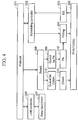
- Fig. 4 shows a configuration example of the wireless base station 1 according to the present embodiment.
- a transmission and reception unit 305 receives a signal transmitted from the wireless camera device 3 and forwards the signal to a protocol processing unit 301 through a reception processing unit 303.
- the wireless base station 1 uses a polling packet generation unit (Polling) 304 to generate a polling packet and wirelessly transmits the generated packet through the transmission and reception unit 305.
- the protocol processing unit 301 receives data transmitted through an upper layer, an Ethernet transmission and reception unit (Ether MAC/PHY) 307, or a LAN controller (LAN controller) 306 and forwards the data to a queue selection unit 308 to execute a forwarding process by wireless transmission as necessary. If the received data is a response frame for the video/voice data of the wireless camera device 3 transmitted from the monitor device 2, the queue selection unit 308 registers the data in a transmission queue for polling access (Queue for PA) 309. If the received data is other data, the queue selection unit 308 registers the data in a transmission queue for carrier sense access (Queue for CSMA) 312.
- the transmission queue for polling access 309 forwards a communication frame registered in a polling access controller 310, and the transmission queue for carrier sense access 312 forwards a communication frame registered in a carrier sense access controller 313.
- the polling access controller 310 adds the communication frame to the polling packet with the same address generated by the polling packet generation unit 304 to thereby perform simultaneous transmission at the polling packet transmission.
- the carrier sense access controller 313 acquires the transmission right based on the carrier sense system and performs wireless transmission through the transmission and reception unit 305 after the acquisition of the transmission right.
- a scheduling controller (Scheduling controller) 302 controls the transmission timing of the polling packet.
- Fig. 5 shows an example of scheduling operation performed by the scheduling controller 302.
- Fig. 6 shows an example of a data structure generated by the scheduling operation.
- the scheduling controller 302 provides an exhaustive polling phase (Exhaustive polling phase) for performing polling of all registered wireless camera devices 3 once, to a first phase of each certain service interval (SI: Service Interval) (step 401).
- Exhaustive polling phase for performing polling of all registered wireless camera devices 3 once, to a first phase of each certain service interval (SI: Service Interval) (step 401).
- the scheduling controller 302 provides, to the next phase, a selective polling phase (Selective polling phase) for selectively executing polling again for the wireless camera device 3, in which normal reception of video/voice data is not confirmed, and further repeating the polling until the normal reception is confirmed (step 402).
- a selective polling phase Selective polling phase
- the scheduling controller 302 sets a carrier sense phase (CSMA phase), in which polling is not performed, in the last phase and provides a contention-based access phase (step 403).
- CSMA phase carrier sense phase
- the carrier sense access controller 313 of the wireless base station 1 or the carrier sense access controller 118 of the wireless camera device 3 obtains the transmission right to start wireless transmission.
- Fig. 7 shows an example of a data structure realized by the wireless surveillance camera system according to the present embodiment.
- the data structure of wireless transmission includes the exhaustive polling phase, the selective polling phase, and the carrier sense phase in each service interval (SI).
- SI service interval
- the polling phase the video or voice data is communicated by contention-free access.
- the carrier sense phase the configuration/control information and other information are communicated by contention-based access.
- the wireless surveillance camera system of the present embodiment low-delay communication in a certain band is provided for the video or voice data, and efficient communication by contention-based access is provided at the same time for the configuration/control data and the like of the camera/wireless device. In this way, a wireless surveillance camera system capable of flexible operation can be provided.
- the scheduling controller 302 can terminate the transmission of polling for the wireless camera device 3 for a certain period (or proceed to polling for another wireless camera device 3).
- Fig. 8 shows an operation example of the scheduling controller 302 terminating the polling when there is no reaction from a specific wireless camera device 3 for M consecutive times.
- the scheduling controller 302 first executes processing operation of changing the transmission destination to the next wireless camera device 3 (step 501). Specifically, 1 is added to an identification number n for specifying the wireless camera device 3. However, if the identification number n+1 after the addition exceeds a maximum number N of wireless camera devices 3 to be polled, the identification number n+1 after the addition is returned to 1 in the operation. Subsequently, the scheduling controller 302 determines whether the number of consecutive non-reactions has reached the maximum number of times M (step 502).
- the scheduling controller 302 If an affirmative result is obtained, the scheduling controller 302 returns to step 501 to change the polling destination because the number of consecutive non-reactions of the corresponding wireless camera device 3 has reached the maximum value. On the other hand, if a negative result is obtained, the scheduling controller 302 executes polling for the corresponding wireless camera device 3 (step 503). Next, the scheduling controller 302 determines the presence or absence of a response (step 504).
- the scheduling controller 302 increments the number of consecutive non-reactions of the corresponding wireless camera device 3 by 1 and returns to step 501 (step 507). If a response is normally received, the scheduling controller 302 transmits ACK (step 505) and clears the number of consecutive non-reactions of the corresponding wireless camera device 3 (step 506).
- the operation can prevent adversely affecting other communications even if the wireless camera device 3 cannot communicate due to a failure, communication path cutoff, or the like.
- the wireless surveillance camera system transmits the video/voice data in the polling system and transmits the camera configuration information and the like other than the video/voice data in the CSMA system.
- the video/voice data and the camera configuration information and the like are transmitted in different communication systems, and thus the band of the video/voice data is not affected even if the camera configuration information is transmitted at the same time as the video/voice data. Therefore, a wireless surveillance camera system capable of transmitting the camera configuration information at the same time can be realized without exerting an influence, such as a delay, on the video/voice data.
- the camera configuration information and the like can be transmitted in the CSMA system, and a situation that the wireless camera device 3 becomes out of control can be prevented.
- the wireless camera devices 3 can be always controlled in this way, the amount of generation of the video/voice data can be optimized in each wireless camera device, and the request band can be changed to a band lower than the transmission band.
- the scheduling controller 302 can stop the polling for the corresponding wireless camera device 3 for a certain period to prevent a situation in which communication of video/voice data between the other wireless camera devices 3 and the wireless base station 1 is disturbed.
- the configuration of a wireless surveillance camera system according to the present embodiment is the same as the configuration of the first embodiment, except for the configuration of the wireless camera device 3.
- Fig. 9 is a configuration example of the wireless camera device 3 used in the wireless surveillance camera system according to a second embodiment.
- the wireless camera device 3 according to the present embodiment has the same configuration as the wireless camera device 3 shown in Fig. 2 , except that a communication performance confirmation unit (Performance) 121 and an identification information categorization unit (Categ.) 122 are added.
- a communication performance confirmation unit (Performance) 121 and an identification information categorization unit (Categ.) 122 are added.
- the communication performance confirmation unit 121 acquires communication parameters, such as the number of polling receptions, the number of ACK receptions, and the number of data transmissions, in the wireless controller 111 and processes the parameters into a data format used for transmission.
- the identification information categorization unit 122 adds identification information indicating the communication parameters and forwards the information to the protocol processing unit 110.
- the protocol processing unit 110 sends out a frame to which the identification information indicating the communication parameters is added, to the queue selection unit 112.
- the queue selection unit 112 determines whether the identification information added to the frame is video/voice data or camera configuration information and communication parameters.
- the queue selection unit 112 registers the frame determined to be a frame including video/voice data in the transmission queue for polling access 113 and registers the frame determined to be a frame including camera configuration information and communication parameters in the transmission queue for carrier sense access 114.
- the information regarding the communication performance collected by the communication performance confirmation unit 121 is wirelessly transmitted to the wireless base station 1 through the carrier sense access controller 118.
- the other operation is the same as in the wireless camera device 3 according to the first embodiment described in Fig. 2 .
- the identification information categorization unit 122 can be omitted from the configuration shown in Fig. 9 .
- the scheduling controller 302 receives and processes the frame transmitted from the wireless camera device 3 to the wireless base station 1.
- the frame received by the scheduling controller 302 includes the communication parameters transmitted from the wireless camera device 3.
- the scheduling controller 302 controls the transmission timing of polling based on the communication parameters. For example, if the communication performance is poor, the scheduling controller 302 instructs to increase the polling frequency to secure the communication quality between the corresponding wireless camera device 3 and the wireless base station 1. If the communication performance is worse, and further increase in the polling frequency affects the communication with other wireless camera devices 3, the scheduling controller 302 can, for example, stop the polling for the wireless camera device 3 (transmission of the response frame for the video/voice data).
- the monitor device 2 shown in Fig. 1 can process the communication parameters transmitted from the wireless camera device 3 as necessary to display communication performance/quality and the like on the screen. Even when the communication performance/quality and the like is not displayed on the screen, the monitor device 2 can use an alarming device not shown (for example, LED and speaker) to alarm and notify the manager when the communication parameter exceeds a threshold.
- an alarming device not shown for example, LED and speaker
- the polling frequency can be adjusted according to the communication performance even if the communication performance is poor in some extent, and robust communication can be provided. Furthermore, the wireless surveillance camera system according to the present embodiment can notify the manager of the performance of communication with each wireless camera device 3 in advance, and measures can be promoted before the occurrence of sudden video cutoff.
- the configuration of a wireless surveillance camera system according to the present embodiment is the same as the configuration of the first embodiment, except for the configuration of the wireless camera device 3.
- Fig. 10 shows a configuration example of the wireless camera device 3 used in the wireless surveillance camera system according to the third embodiment.
- the same reference signs are provided to the parts corresponding to Fig. 2 .
- the wireless camera device 3 includes: the camera device (Camera device) 101; a first Ethernet transmission and reception unit (Ether MAC/PHY) 132a; a first processor (Processor) 102a connected to the camera device 101 and the first Ethernet transmission and reception unit 132a; the main memory device (Memory) 104; a second Ethernet transmission and reception unit 132b connected to the first Ethernet transmission and reception unit 132a through an Ethernet cable; the wireless device (Wireless device) 103; and a second processor 102b connected to the second Ethernet transmission and reception unit 132b and the wireless device 103.
- a housing for mounting the camera device 101 and a housing for mounting the wireless device 103 are separate housings in the wireless camera device 3.
- the video and voice data acquired by the camera device 101 is forwarded to the first processor 102a.
- the camera signal processor 105 applies signal processing, such as image compression, to the input video and voice data to process the data into a data format used for wireless transmission.
- the processed video or voice data is provided to the identification information categorization unit (Categ.) 106.
- the identification information categorization unit 106 adds identification information indicating the video or voice data to the processed video or voice data and transmits the data to a protocol processing unit (Protocol) 110a.
- Protocol protocol processing unit
- the first processor 102a also includes a configuration unit (Configuration) 107a and a communication tool (Comm. Tool) 108a.
- the configuration unit 107a provides, for example, an interface for remote operation from another wireless camera device 3 or operation terminal, acquires configuration information related to video parameters and wireless parameters, and reflects and saves the configuration.
- the communication tool 108a provides, for example, a Web server, a CUI (Command User Interface) server, and the like.
- the communication tool 108a of the first processor receives configuration/control data transmitted from another terminal and forwards configuration information related to the wireless camera, such as configuration information of the camera signal processor 105 and the like, to the configuration unit 107a.
- the communication tool 108a acquires configuration information related to the wireless camera device 3, such as configuration information of the camera signal processor 105 and the like, through the configuration unit 107a and processes the information into a data format used for transmission.
- An identification information categorization unit (Categ.) 109a adds identification information indicating the configuration information data to the processed configuration information data and transmits the data to the protocol processing unit 110a.
- the protocol processing unit 110a of the first processor 102a applies processing of transport layer and network layer, such as TCP/IP, to the transmitted data as necessary to generate a communication frame and transmits the communication frame to the first Ethernet transmission and reception unit 132a through a LAN controller (LAN controller 131a).
- transport layer and network layer such as TCP/IP
- the first Ethernet transmission and reception unit 132a transmits the communication frame to the second Ethernet transmission and reception unit 132b through an Ethernet cable. Through the transmission, the communication frame generated by the first processor 102a is forward to the second processor 102b.
- a LAN controller 131b of the second processor 102b processes the received communication frame and transmits the frame to a protocol processing unit 110b.
- the second processor 102b includes a configuration unit (Configuration) 107b and a communication tool (Comm. Tool) 108b.
- the configuration unit 107b provides an interface for remote operation from another wireless camera device 3 or operation terminal, acquires configuration information related to wireless parameters, and reflects and saves the configuration.
- the communication tool 108b provides, for example, a Web server and a CUI (Command User Interface) server.
- the communication tool 108b receives configuration/control data transmitted from another terminal and forwards configuration information related to the wireless camera device 3, such as configuration information in the wireless controller 111 and the like, to the configuration unit 107b.
- the communication tool 108b acquires configuration information related to the wireless camera device 3, such as configuration information in the wireless controller 103 and the like, and processes the information into a data format used for transmission.
- An identification information categorization unit (Categ.) 109b adds identification information indicating the configuration information data to the processed configuration information data and transmits the data to the protocol processing unit 110b.
- the protocol processing unit 110b of the second processor 102b applies processing of transport layer and network layer, such as TCP/IP, or protocol processing of IEEE 802.11 as necessary to the transmitted data and forwards the data to the wireless controller (Wireless controller) 111.
- transport layer and network layer such as TCP/IP
- protocol processing of IEEE 802.11 as necessary to the transmitted data and forwards the data to the wireless controller (Wireless controller) 111.
- the queue selection unit (Select) 112 of the wireless controller 111 determines the registration destination of the communication frame according to the identification information added to the generated communication frame. For example, the queue selection unit 112 registers the communication frame of video or voice data in the transmission queue for polling access (Queue for polling access) 113 and registers the communication frame of configuration information data in the transmission queue for carrier sense access (Queue for CSMA) 114.
- the interface controller (I/F Controller) 115 of the second processor 102b controls exchange of information between the wireless device 103 and the processor 102b.
- the communication frame of the transmission queue for polling access 113 is transmitted to the polling access controller (PA) 117 of the wireless device 111, and the communication frame of the transmission queue for carrier sense access 114 is transmitted to the carrier sense access controller (CSMA) 118 of the wireless device 103.
- PA polling access controller
- CSMA carrier sense access controller
- the polling access controller 117 of the wireless device 103 acquires the transmission right through the reception of a polling packet addressed to the station and transmits the communication frame to the transmission and reception unit (PHY (TX/RX)) 119 after the acquisition of the transmission right to perform wireless transmission.
- the carrier sense access controller 118 of the wireless device 103 acquires the transmission right based on the carrier sense system and transmits the communication frame to the transmission and reception unit 119 after the acquisition of the transmission right to perform wireless transmission.
- the wireless device 103 also includes the processing unit (RX) 120 that receives the communication frame received from the transmission and reception unit 119 to forward the communication frame to the processor 102b.
- RX processing unit
- the identification information categorization unit 109 adds the identification information to the configuration information data transmitted based on the carrier sense system in this embodiment, the identification information categorization unit 109 is not always necessary. Since the identification information is added to the video or voice data, the queue selection unit 112 can select the transmission queue for carrier sense access 114 if the identification information is not added.
- a certain band and low-delay communication can be provided for the video or voice data even when the camera device 101 and the wireless device 103 are not physically in the same housing, and at the same time, efficient best-effort communication can be provided for the configuration/control data and the like of the camera/wireless device.
- Ethernet cable is used for the communication between the first processor 102a and the second processor 102b in the description of the present embodiment, the arrangement is not limited to this. This is because an interface such as a USB can also be used, for example.
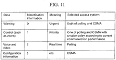
- Fig. 11 shows an example of a correspondence.
- the configuration information (identification information 3) is communicated in the CSMA system
- the voice or video data (identification information 2) is communicated in the polling system. If it is defined that the communication is to be performed in the CSMA system when the identification information is not added, the identification information may not be added to the configuration information.
- a control signal (identification information 1) of zoom, pan, or the like that requires low-delay control is communicated by using one of the polling system and the CSMA system with a smaller delay according to the current communication performance. This is because the real-time property of the control of zoom or pan of the wireless surveillance camera is high in the wireless surveillance camera system.
- the current communication performance can be recognized by monitoring the number of polling transmissions and receptions, the number of ACK receptions, the number of data transmissions, and the like in the wireless camera device 3 and the wireless base station 102.
- a mechanism of selecting the system used for the communication based on the recognize result can be provided in the wireless camera device 3 and the wireless base station 102 to realize the control.
- An urgent warning signal (identification information 0) is communicated by using both of the polling system and the CSMA system because the data needs to be transferred as early as possible.
Landscapes
- Engineering & Computer Science (AREA)
- Signal Processing (AREA)
- Multimedia (AREA)
- Computer Networks & Wireless Communication (AREA)
- Physics & Mathematics (AREA)
- General Physics & Mathematics (AREA)
- Human Computer Interaction (AREA)
- Business, Economics & Management (AREA)
- General Business, Economics & Management (AREA)
- Closed-Circuit Television Systems (AREA)
- Mobile Radio Communication Systems (AREA)
- Alarm Systems (AREA)
- Telephonic Communication Services (AREA)
Description
- The present invention relates to a surveillance camera system and a surveillance camera device with a wireless communication function.
- There are a large number of conventional techniques in which a wireless communication technique is applied to a surveillance camera system (for example,
Patent Literature 1 and Patent Literature 2). For example, systems for transmitting a video taken by a surveillance camera through a wireless LAN (Local Area Network) are disclosed inPatent Literature Patent Literature 3. - Conventionally, two functions, DCF (Distributed Coordination Access) and PCF (Point Coordination Channel Access) are defined in the MAC of IEEE 802.11 standard. Furthermore, EDCA (Enhanced Distributed Channel Access) with QoS characteristics obtained by extending the DCF and HCCA (Hybrid coordinated function Controlled Channel Access) obtained by extending the PCF are defined in extended MAC of IEEE 802.11e.
- The DCF and the EDCA are systems based on CSMA (Carrier Sense Multiple Access), and contention-based access means is provided to a tenninal. The PCF and the HC-CA are access methods using a polling system, and contention-free access means is provided to a tenninal. A reference scheduling method using the HCCA is also disclosed in the IEEE 802.11e standard.
-
- Patent Literature 1:
JP 2009-124302 A - Patent Literature 2:
JP 2009-141547 A - Patent Literature 3:
JP 2010-178347 A -
US 2009/189981 A1 discloses a wireless video transmission system using polling-based and contention-based transmission in different transmission channels.WO 03/094451 A1 - In a surveillance camera system, the taken video and/or voice data needs to be transmitted in real time without a delay, at a certain throughput (that is, QoS needs to be secured in the transmission). However, it is difficult to satisfy this request by the conventional wireless techniques.
- An example of a wireless technique for providing the QoS includes a method of using the EDCA or the HCCA defined in the IEEE 802.11e standard. However, the following problems may occur in applying the EDCA or the HCCA to the surveillance camera system.
- First, in the surveillance camera system, communication of configuration information, control infonnation, and the like is necessary at the same time as the exchange of video and/or voice data. However, if the configuration information and the like are communicated at the same time by the same communication system as that of the video and/or voice data, the communication band of the video and/or voice data may be tightened by the configuration information and the like, and this may increase the transmission delay of the video and/or voice data. On the other hand, the system of communicating the configuration information and the like at the same time by the same communication system as that of the video and/or voice data may also increase the communication delay of data (for example, configuration information and control signal) other than the video or voice data.
- Furthermore, when the reference scheduling method disclosed in IEEE 802.11e is applied to the surveillance camera system, a large number of retransmission opportunities need to be provided to the terminal in case that the wireless state is poor, and there is a problem that the transmission becomes inefficient. The increase in the retransmission opportunities also causes unreasonable occupation of transmission band, and communication by other wireless camera devices may be disturbed.
- The present invention has been made in view of the technical problems, and the present invention provides a wireless surveillance camera system that can efficiently communicate configuration information of a camera device and a wireless device at the same time while ensuring a certain band and low-delay communication of video and/or voice data.
- The present invention is defined in the independent claims. Further advantageous features are set out in the dependent claims.
- An invention as a first solution is a wireless surveillance camera system including: (1) at least one wireless surveillance camera device including a camera device and a wireless device; and (2) a wireless base station that receives a wireless signal transmitted from the wireless surveillance camera device, and the wireless surveillance camera device and the wireless base station have the following features.
-
- (1) The wireless base station includes: a transmission unit that wirelessly transmits a generated polling packet to each wireless surveillance camera device in a polling system; and a scheduling controller that controls transmission timing of the polling packet.
- (2) The wireless surveillance camera device is (1) at least one wireless surveillance camera device including a camera device and a wireless device, the wireless surveillance camera device including: a signal processing unit that applies signal processing to video and/or voice data from the camera device; (2) an identification information categorization unit that adds identification information to the video data and/or voice data after the signal processing; (3) a configuration unit that acquires configuration information data (for example, video parameters and wireless parameters) related to video parameters and/or wireless parameters inside of the device; (4) a protocol processing unit that applies protocol processing (for example, network layer, transport layer, IEEE 802.11 protocol, and the like) to the video and/or voice data and the configuration information data to generate a communication frame; (5) at least one first transmission queue associated with a polling system (non-competitive access); (6) at least one second transmission queue associated with a carrier sense access system (competitive access); (7) a selection unit that refers to the identification information added to the communication frame to forward the video and/or voice data to the first transmission queue associated with the polling system and to forward the configuration information data to the second transmission queue associated with the carrier access system; (8) an interface controller that forwards the communication frames stored in the first and second transmission queues to the wireless device; and the wireless device including: (9) a first access controller that acquires a transmission right in the polling system; (10) a second access controller that acquires a transmission right in the carrier sense system; and (11) a transmission unit that wirelessly transmits the communication frames received from the first and second transmission queues at timings that the corresponding transmission rights are obtained.
- In an invention as a second solution, the following function is added to the scheduling controller of the wireless base station in the wireless surveillance camera system according to the first solution. Specifically, added is a function of dividing one service interval into an exhaustive polling phase, a selective polling phase, and a carrier sense phase; scheduling polling for a registered wireless surveillance camera device at least once in the exhaustive polling phase; repeatedly scheduling polling for a wireless surveillance camera, for which a return frame for the polling is not normally received in the service interval, in the selective polling phase; and scheduling an access opportunity in the carrier sense system in the carrier sense phase without transmitting polling.
- In an invention as a third solution, the following function is added to the wireless surveillance camera device in the wireless surveillance camera system according to the first solution. Specifically, added is a function of counting communication parameters (the number of polling receptions, the number of ACK receptions, and the like) indicating a state of communication with the wireless base station and generating; and transmitting a packet so as to forward the communication parameters to the second transmission queue associated with the carrier sense system.
- According to the present invention, efficient transmission of configuration information in the wireless surveillance camera device can be realized at the same time while ensuring a certain band and low-delay communication of video and/or voice data. Other problems, configurations, and advantageous effects will become apparent from the description of the following embodiments.
-
-
Fig. 1 is a diagram showing a configuration example of a wireless surveillance camera system according to a first embodiment. -
Fig. 2 is a diagram showing a configuration example of a wireless camera according to the first embodiment. -
Fig. 3 is a flow chart showing an example of a data transmission procedure by the wireless camera according to the first embodiment. -
Fig. 4 is a diagram showing a configuration example of a wireless base station according to the first embodiment. -
Fig. 5 is a flow chart showing an operation example of a scheduling controller in the wireless base station according to the first embodiment. -
Fig. 6 is a diagram showing an example of a data structure based on the scheduling controller in the wireless base station according to the first embodiment. -
Fig. 7 is a diagram showing an example of a data structure in the wireless surveillance camera system according to the first embodiment. -
Fig. 8 is a flow chart showing an example of operation of handling a non-reaction terminal by the scheduling controller according to the first embodiment. -
Fig. 9 is a diagram showing a configuration example of a wireless camera included in a wireless surveillance camera system according to a second embodiment. -
Fig. 10 is a diagram showing a configuration example of a wireless camera included in a wireless surveillance camera system according to a third embodiment. -
Fig. 11 is an example of a table indicating a selection relationship between data types and access systems. - When the number of elements or the like (including the number, numerical value, quantity, range, and the like) is mentioned in the following description, the number is not limited to the specific number, and the number may be greater or smaller than the specific number, unless otherwise particularly specified or when the number is clearly limited to the specific number in principle. In the following embodiments, the constituent elements (including element steps and the like) are not always essential, unless otherwise particularly specified or when the constituent elements are clearly essential in principle.
- In the following description, part or all of the configurations, functions, processing units, processing means, and the like may be realized by, for example, integrated circuits or other hardware. A processor may interpret and execute programs for realizing functions to realize the configurations, the functions, and the like. More specifically, the configurations, the functions, and the like may be realized by software. Information of the programs, tables, files, and the like for realizing the functions can be stored in a memory, a memory device such as a hard disk and an SSD (Solid State Drive), or a storage medium such as an IC card, an SD card, and a DVD.
- Furthermore, control lines and information lines considered necessary for the description are illustrated, and not all control lines and information lines necessary for the product are illustrated. It can be considered that in reality, almost all of the components are mutually connected.
-
Fig. 1 is a configuration example of a wireless surveillance camera system according to a first embodiment. The wireless surveillance camera system shown inFig. 1 includes a wireless base station (AP) 1, a monitor device (Monitor) 2, and wireless camera devices (Wireless Cameras) 3. In the case ofFig. 1 , a plurality ofwireless camera devices 3 communicate with thewireless base station 1. - The
monitor device 2 receives and displays video and/or voice data transmitted from thewireless camera devices 3. Themonitor device 2 also provides a user interface function and a communication function for acquiring, configuring, and controlling configuration information of thewireless camera devices 3 as necessary. The configuration information includes, for example, configuration information of video parameters, configuration information of wireless parameters, and the like. - The configuration information of video parameters includes, for example, (1) codec information (type of codec (H.264, MPEG, or M-JPEG), image quality (compressibility), resolution, coded bit rate, and frame rate), (2) camera configuration information (whether to perform backlight correction, photometric area, whether to perform gamma correction, color level adjustment, black level adjustment, contour correction, zoom magnification, direction of camera, and the like), (3) voice information (codec, bit rate, reception timeout, microphone input level, line output level, and input mute level), and (4) other information (date information and NTP synchronization setting).
- The configuration information of wireless parameters includes, for example, (1) network basic configuration information (IP address, DNS (Dynamic Name Resolution) information, port information, MTU (Maximum Transmission Unit) size, retransmission timeout time, ARP (Address Resolution Protocol) transmission time, and IP filter information), (2) user authentication information (ON/OFF of user authentication function and user configuration information (user name, password, and authority)), and (3) wireless configuration information (encryption key configuration, mode switching, transmission output change, carrier sense level change, and the like).
- Although not written in
Fig. 1 , a memory device that stores video data (for example, hard disk device or storage device) and a computer for configuration may be connected to themonitor device 2. -
Fig. 2 shows a configuration example of thewireless camera device 3, andFig. 3 shows a data transmission procedure executed by thewireless camera device 3. - As shown in
Fig. 2 , thewireless camera device 3 includes a camera device (Camera device) 101, a processor (Processor) 102, a wireless device (Wireless device) 103, and a main memory device (Memory) 104. Thecamera device 101 according to the present embodiment also includes an imaging optical system not shown, an imaging element (for example, CMOS sensor), a microphone not shown, a function of outputting video data of images taken by the imaging element, and a function of outputting voice data of sound collected by the microphone. - Video or voice data acquired by the
camera device 101 is forwarded to theprocessor 102. Acamera signal processor 105 in theprocessor 102 applies signal processing, such as image compression, to the input video and voice data to process the data into a data format used for transmission (step 201). An identification information categorization unit (Categ.) 106 adds identification information, indicating the video or voice data, to the processed video or voice data and transmits the data to a protocol processing unit (Protocol) 110 (step 203). - The
processor 102 also includes a configuration unit (Configuration) 107 and a communication tool (Comm. tool) 108. Theconfiguration unit 107 provides, for example, an interface for remote operation from another wireless camera device or operation terminal, acquires configuration information related to video parameters and wireless parameters, and reflects and saves the configuration. - The configuration information here includes, for example, configuration information of video parameters, configuration information of wireless parameters, and the like.
- The configuration information of video parameters includes, for example, (1) codec information (type of codec (H.264, MPEG, or M-JPEG), image quality (compressibility), resolution, coded bit rate, and frame rate), (2) camera configuration information (whether to perform backlight correction, photometric area, whether to perform gamma correction, color level adjustment, black level adjustment, contour correction, zoom magnification, direction of camera, and the like), (3) voice information (codec, bit rate, reception timeout, microphone input level, line output level, and input mute level), and (4) other information (date information and NTP synchronization setting).
- The configuration information of wireless parameters includes, for example, (1) network basic configuration information (IP address, DNS (Dynamic Name Resolution) information, port information, MTU (Maximum Transmission Unit) size, retransmission timeout time, ARP (Address Resolution Protocol) transmission time, and IP filter information), (2) user authentication (ON/OFF of user authentication function and user configuration information (user name, password, and authority)), and (3) wireless configuration information (encryption key configuration, mode switching, transmission output change, carrier sense level change, and the like).
- The
communication tool 108 provides, for example, a Web server, a CUI (Command User Interface) server, and the like. Thecommunication tool 108 receives configuration/control data transmitted from another terminal and forwards configuration information related to thewireless camera device 3, such as configuration information of thecamera signal processor 105 and awireless controller 111, to the configuration unit 107 (step 202). Thecommunication tool 108 also acquires configuration information data related to thewireless camera device 3, such as configuration information data of thecamera signal processor 105 or thewireless controller 111, through theconfiguration unit 107 and processes the data into a data format used for transmission. An identification information categorization unit (Categ.) 109 adds identification information indicating the configuration information data to the processed configuration information data and transmits the data to the protocol processing unit 110 (step 203). - The
protocol processing unit 110 applies processing of transport layer and network layer, such as TCP/IP, or protocol processing of IEEE 802.11 to the transmitted data to generate a communication frame and transmits the communication frame to the wireless controller (Wireless controller) 111 (step 204). - A queue selection unit (Select) 112 of the
wireless controller 111 determines whether the identification information added to the generated communication frame is video/voice data or camera configuration information (step 205). The queue selection unit (Select) 112 registers the communication frame of video or voice data in a transmission queue for polling access (Queue for polling access) 113 (step 206) and registers the communication frame of configuration information data in a transmission queue for carrier sense access (Queue for CSMA) 114 (step 208). - Interface controllers (I/F Controllers) 115 and 116 control exchange of information between the
wireless device 103 and theprocessor 102. The communication frame of the transmission queue forpolling access 113 is transmitted to a polling access controller (PA) 117 of thewireless device 103, and the communication frame of the transmission queue forcarrier sense access 114 is transmitted to a carrier sense access controller (CSMA) 118 of the wireless device 103 (steps 207 and 209). - The
polling access controller 117 of thewireless device 103 acquires a transmission right through the reception of a polling packet addressed to the station and transmits the communication frame to a transmission and reception unit (PHY (TX/RX)) 119 after the acquisition of the transmission right to perform wireless transmission. - The carrier
sense access controller 118 of thewireless device 103 acquires a transmission right based on a carrier sense system and transmits the communication frame to the transmission andreception unit 119 after the acquisition of the transmission right to perform wireless transmission. - The
wireless device 103 also includes a processing unit (RX) 120 that receives the wireless frame received from the transmission andreception unit 119 to forward the wireless frame to theprocessor 102. - Although the identification
information categorization unit 109 adds the identification information to the configuration information data transmitted based on the carrier sense system in this embodiment, the identificationinformation categorization unit 109 can be omitted. This is because when the identification information is added to the video or voice data, thequeue selection unit 112 can determine that the communication frame without the addition of the identification information is the configuration information data and can register the data in the transmission queue forcarrier sense access 114. - Although one
processor 102 executes all of the processes in the description of the present embodiment, a configuration that a plurality of processors share and execute the processes may be adopted. For example, a dedicated LSI can be used to form thecamera signal processor 105. -
Fig. 4 shows a configuration example of thewireless base station 1 according to the present embodiment. In thewireless base station 1, a transmission andreception unit 305 receives a signal transmitted from thewireless camera device 3 and forwards the signal to aprotocol processing unit 301 through areception processing unit 303. - The
wireless base station 1 uses a polling packet generation unit (Polling) 304 to generate a polling packet and wirelessly transmits the generated packet through the transmission andreception unit 305. Theprotocol processing unit 301 receives data transmitted through an upper layer, an Ethernet transmission and reception unit (Ether MAC/PHY) 307, or a LAN controller (LAN controller) 306 and forwards the data to aqueue selection unit 308 to execute a forwarding process by wireless transmission as necessary. If the received data is a response frame for the video/voice data of thewireless camera device 3 transmitted from themonitor device 2, thequeue selection unit 308 registers the data in a transmission queue for polling access (Queue for PA) 309. If the received data is other data, thequeue selection unit 308 registers the data in a transmission queue for carrier sense access (Queue for CSMA) 312. - The transmission queue for
polling access 309 forwards a communication frame registered in apolling access controller 310, and the transmission queue forcarrier sense access 312 forwards a communication frame registered in a carriersense access controller 313. - The
polling access controller 310 adds the communication frame to the polling packet with the same address generated by the pollingpacket generation unit 304 to thereby perform simultaneous transmission at the polling packet transmission. - The carrier
sense access controller 313 acquires the transmission right based on the carrier sense system and performs wireless transmission through the transmission andreception unit 305 after the acquisition of the transmission right. - A scheduling controller (Scheduling controller) 302 controls the transmission timing of the polling packet.
-
Fig. 5 shows an example of scheduling operation performed by thescheduling controller 302.Fig. 6 shows an example of a data structure generated by the scheduling operation. - The
scheduling controller 302 provides an exhaustive polling phase (Exhaustive polling phase) for performing polling of all registeredwireless camera devices 3 once, to a first phase of each certain service interval (SI: Service Interval) (step 401). - The
scheduling controller 302 provides, to the next phase, a selective polling phase (Selective polling phase) for selectively executing polling again for thewireless camera device 3, in which normal reception of video/voice data is not confirmed, and further repeating the polling until the normal reception is confirmed (step 402). - The
scheduling controller 302 sets a carrier sense phase (CSMA phase), in which polling is not performed, in the last phase and provides a contention-based access phase (step 403). In the carrier sense phase, the carriersense access controller 313 of thewireless base station 1 or the carriersense access controller 118 of thewireless camera device 3 obtains the transmission right to start wireless transmission. -
Fig. 7 shows an example of a data structure realized by the wireless surveillance camera system according to the present embodiment. The data structure of wireless transmission includes the exhaustive polling phase, the selective polling phase, and the carrier sense phase in each service interval (SI). In the polling phase, the video or voice data is communicated by contention-free access. In the carrier sense phase, the configuration/control information and other information are communicated by contention-based access. - According to the wireless surveillance camera system of the present embodiment, low-delay communication in a certain band is provided for the video or voice data, and efficient communication by contention-based access is provided at the same time for the configuration/control data and the like of the camera/wireless device. In this way, a wireless surveillance camera system capable of flexible operation can be provided.
- Furthermore, when a response is not obtained for consecutive M times (preset maximum number of times) in response to the polling for a specific
wireless camera device 3, thescheduling controller 302 can terminate the transmission of polling for thewireless camera device 3 for a certain period (or proceed to polling for another wireless camera device 3). -
Fig. 8 shows an operation example of thescheduling controller 302 terminating the polling when there is no reaction from a specificwireless camera device 3 for M consecutive times. Thescheduling controller 302 first executes processing operation of changing the transmission destination to the next wireless camera device 3 (step 501). Specifically, 1 is added to an identification number n for specifying thewireless camera device 3. However, if the identification number n+1 after the addition exceeds a maximum number N ofwireless camera devices 3 to be polled, the identification number n+1 after the addition is returned to 1 in the operation. Subsequently, thescheduling controller 302 determines whether the number of consecutive non-reactions has reached the maximum number of times M (step 502). If an affirmative result is obtained, thescheduling controller 302 returns to step 501 to change the polling destination because the number of consecutive non-reactions of the correspondingwireless camera device 3 has reached the maximum value. On the other hand, if a negative result is obtained, thescheduling controller 302 executes polling for the corresponding wireless camera device 3 (step 503). Next, thescheduling controller 302 determines the presence or absence of a response (step 504). - If there is no response, the
scheduling controller 302 increments the number of consecutive non-reactions of the correspondingwireless camera device 3 by 1 and returns to step 501 (step 507). If a response is normally received, thescheduling controller 302 transmits ACK (step 505) and clears the number of consecutive non-reactions of the corresponding wireless camera device 3 (step 506). - The operation can prevent adversely affecting other communications even if the
wireless camera device 3 cannot communicate due to a failure, communication path cutoff, or the like. - As described, the wireless surveillance camera system according to the present embodiment transmits the video/voice data in the polling system and transmits the camera configuration information and the like other than the video/voice data in the CSMA system. In this way, the video/voice data and the camera configuration information and the like are transmitted in different communication systems, and thus the band of the video/voice data is not affected even if the camera configuration information is transmitted at the same time as the video/voice data. Therefore, a wireless surveillance camera system capable of transmitting the camera configuration information at the same time can be realized without exerting an influence, such as a delay, on the video/voice data.
- Furthermore, even if the allocated band for the video/voice data is smaller than the request band due to poor transmission performance (even if the transmission band of the video/voice data reaches the limit value), the camera configuration information and the like can be transmitted in the CSMA system, and a situation that the
wireless camera device 3 becomes out of control can be prevented. When thewireless camera devices 3 can be always controlled in this way, the amount of generation of the video/voice data can be optimized in each wireless camera device, and the request band can be changed to a band lower than the transmission band. - Furthermore, according to the wireless surveillance camera system of the present embodiment, even if the entire transmission band is occupied due to deterioration in the performance of transmission of video/voice data to and from a specific
wireless camera device 3 using polling, thescheduling controller 302 can stop the polling for the correspondingwireless camera device 3 for a certain period to prevent a situation in which communication of video/voice data between the otherwireless camera devices 3 and thewireless base station 1 is disturbed. - The configuration of a wireless surveillance camera system according to the present embodiment is the same as the configuration of the first embodiment, except for the configuration of the
wireless camera device 3. -
Fig. 9 is a configuration example of thewireless camera device 3 used in the wireless surveillance camera system according to a second embodiment. InFig. 9 , the same reference signs are provided to the parts corresponding toFig. 2 . Thewireless camera device 3 according to the present embodiment has the same configuration as thewireless camera device 3 shown inFig. 2 , except that a communication performance confirmation unit (Performance) 121 and an identification information categorization unit (Categ.) 122 are added. - The communication
performance confirmation unit 121 acquires communication parameters, such as the number of polling receptions, the number of ACK receptions, and the number of data transmissions, in thewireless controller 111 and processes the parameters into a data format used for transmission. The identificationinformation categorization unit 122 adds identification information indicating the communication parameters and forwards the information to theprotocol processing unit 110. Theprotocol processing unit 110 sends out a frame to which the identification information indicating the communication parameters is added, to thequeue selection unit 112. - The
queue selection unit 112 determines whether the identification information added to the frame is video/voice data or camera configuration information and communication parameters. Thequeue selection unit 112 registers the frame determined to be a frame including video/voice data in the transmission queue forpolling access 113 and registers the frame determined to be a frame including camera configuration information and communication parameters in the transmission queue forcarrier sense access 114. - In this way, the information regarding the communication performance collected by the communication
performance confirmation unit 121 is wirelessly transmitted to thewireless base station 1 through the carriersense access controller 118. - The other operation is the same as in the
wireless camera device 3 according to the first embodiment described inFig. 2 . - If it is defined that the
queue selection unit 112 registers the frame to which the identification information is not added in the transmission queue forcarrier sense access 114, the identificationinformation categorization unit 122 can be omitted from the configuration shown inFig. 9 . - The scheduling controller 302 (
Fig. 4 ) receives and processes the frame transmitted from thewireless camera device 3 to thewireless base station 1. In the present embodiment, the frame received by thescheduling controller 302 includes the communication parameters transmitted from thewireless camera device 3. Thescheduling controller 302 controls the transmission timing of polling based on the communication parameters. For example, if the communication performance is poor, thescheduling controller 302 instructs to increase the polling frequency to secure the communication quality between the correspondingwireless camera device 3 and thewireless base station 1. If the communication performance is worse, and further increase in the polling frequency affects the communication with otherwireless camera devices 3, thescheduling controller 302 can, for example, stop the polling for the wireless camera device 3 (transmission of the response frame for the video/voice data). - The
monitor device 2 shown inFig. 1 can process the communication parameters transmitted from thewireless camera device 3 as necessary to display communication performance/quality and the like on the screen. Even when the communication performance/quality and the like is not displayed on the screen, themonitor device 2 can use an alarming device not shown (for example, LED and speaker) to alarm and notify the manager when the communication parameter exceeds a threshold. - In the wireless surveillance camera system according to the present embodiment, the polling frequency can be adjusted according to the communication performance even if the communication performance is poor in some extent, and robust communication can be provided. Furthermore, the wireless surveillance camera system according to the present embodiment can notify the manager of the performance of communication with each
wireless camera device 3 in advance, and measures can be promoted before the occurrence of sudden video cutoff. - The configuration of a wireless surveillance camera system according to the present embodiment is the same as the configuration of the first embodiment, except for the configuration of the
wireless camera device 3. -
Fig. 10 shows a configuration example of thewireless camera device 3 used in the wireless surveillance camera system according to the third embodiment. InFig. 10 , the same reference signs are provided to the parts corresponding toFig. 2 . - The
wireless camera device 3 according to the present embodiment includes: the camera device (Camera device) 101; a first Ethernet transmission and reception unit (Ether MAC/PHY) 132a; a first processor (Processor) 102a connected to thecamera device 101 and the first Ethernet transmission andreception unit 132a; the main memory device (Memory) 104; a second Ethernet transmission andreception unit 132b connected to the first Ethernet transmission andreception unit 132a through an Ethernet cable; the wireless device (Wireless device) 103; and asecond processor 102b connected to the second Ethernet transmission andreception unit 132b and thewireless device 103. - In the present embodiment, a housing for mounting the
camera device 101 and a housing for mounting thewireless device 103 are separate housings in thewireless camera device 3. - In the present embodiment, the video and voice data acquired by the
camera device 101 is forwarded to thefirst processor 102a. In thefirst processor 102a, thecamera signal processor 105 applies signal processing, such as image compression, to the input video and voice data to process the data into a data format used for wireless transmission. The processed video or voice data is provided to the identification information categorization unit (Categ.) 106. The identificationinformation categorization unit 106 adds identification information indicating the video or voice data to the processed video or voice data and transmits the data to a protocol processing unit (Protocol) 110a. - The
first processor 102a also includes a configuration unit (Configuration) 107a and a communication tool (Comm. Tool) 108a. Theconfiguration unit 107a provides, for example, an interface for remote operation from anotherwireless camera device 3 or operation terminal, acquires configuration information related to video parameters and wireless parameters, and reflects and saves the configuration. Thecommunication tool 108a provides, for example, a Web server, a CUI (Command User Interface) server, and the like. - The
communication tool 108a of the first processor receives configuration/control data transmitted from another terminal and forwards configuration information related to the wireless camera, such as configuration information of thecamera signal processor 105 and the like, to theconfiguration unit 107a. Thecommunication tool 108a acquires configuration information related to thewireless camera device 3, such as configuration information of thecamera signal processor 105 and the like, through theconfiguration unit 107a and processes the information into a data format used for transmission. An identification information categorization unit (Categ.) 109a adds identification information indicating the configuration information data to the processed configuration information data and transmits the data to theprotocol processing unit 110a. - The
protocol processing unit 110a of thefirst processor 102a applies processing of transport layer and network layer, such as TCP/IP, to the transmitted data as necessary to generate a communication frame and transmits the communication frame to the first Ethernet transmission andreception unit 132a through a LAN controller (LAN controller 131a). - The first Ethernet transmission and
reception unit 132a transmits the communication frame to the second Ethernet transmission andreception unit 132b through an Ethernet cable. Through the transmission, the communication frame generated by thefirst processor 102a is forward to thesecond processor 102b. ALAN controller 131b of thesecond processor 102b processes the received communication frame and transmits the frame to aprotocol processing unit 110b. - The
second processor 102b includes a configuration unit (Configuration) 107b and a communication tool (Comm. Tool) 108b. Theconfiguration unit 107b provides an interface for remote operation from anotherwireless camera device 3 or operation terminal, acquires configuration information related to wireless parameters, and reflects and saves the configuration. Thecommunication tool 108b provides, for example, a Web server and a CUI (Command User Interface) server. Thecommunication tool 108b receives configuration/control data transmitted from another terminal and forwards configuration information related to thewireless camera device 3, such as configuration information in thewireless controller 111 and the like, to theconfiguration unit 107b. Thecommunication tool 108b acquires configuration information related to thewireless camera device 3, such as configuration information in thewireless controller 103 and the like, and processes the information into a data format used for transmission. An identification information categorization unit (Categ.) 109b adds identification information indicating the configuration information data to the processed configuration information data and transmits the data to theprotocol processing unit 110b. - The
protocol processing unit 110b of thesecond processor 102b applies processing of transport layer and network layer, such as TCP/IP, or protocol processing of IEEE 802.11 as necessary to the transmitted data and forwards the data to the wireless controller (Wireless controller) 111. - The queue selection unit (Select) 112 of the
wireless controller 111 determines the registration destination of the communication frame according to the identification information added to the generated communication frame. For example, thequeue selection unit 112 registers the communication frame of video or voice data in the transmission queue for polling access (Queue for polling access) 113 and registers the communication frame of configuration information data in the transmission queue for carrier sense access (Queue for CSMA) 114. - The interface controller (I/F Controller) 115 of the
second processor 102b controls exchange of information between thewireless device 103 and theprocessor 102b. The communication frame of the transmission queue forpolling access 113 is transmitted to the polling access controller (PA) 117 of thewireless device 111, and the communication frame of the transmission queue forcarrier sense access 114 is transmitted to the carrier sense access controller (CSMA) 118 of thewireless device 103. - The
polling access controller 117 of thewireless device 103 acquires the transmission right through the reception of a polling packet addressed to the station and transmits the communication frame to the transmission and reception unit (PHY (TX/RX)) 119 after the acquisition of the transmission right to perform wireless transmission. The carriersense access controller 118 of thewireless device 103 acquires the transmission right based on the carrier sense system and transmits the communication frame to the transmission andreception unit 119 after the acquisition of the transmission right to perform wireless transmission. - The
wireless device 103 also includes the processing unit (RX) 120 that receives the communication frame received from the transmission andreception unit 119 to forward the communication frame to theprocessor 102b. - Although the identification
information categorization unit 109 adds the identification information to the configuration information data transmitted based on the carrier sense system in this embodiment, the identificationinformation categorization unit 109 is not always necessary. Since the identification information is added to the video or voice data, thequeue selection unit 112 can select the transmission queue forcarrier sense access 114 if the identification information is not added. - According to the wireless surveillance system of the present embodiment, a certain band and low-delay communication can be provided for the video or voice data even when the
camera device 101 and thewireless device 103 are not physically in the same housing, and at the same time, efficient best-effort communication can be provided for the configuration/control data and the like of the camera/wireless device. - Although the Ethernet cable is used for the communication between the
first processor 102a and thesecond processor 102b in the description of the present embodiment, the arrangement is not limited to this. This is because an interface such as a USB can also be used, for example. - Lastly, an example of adding identification information to data and an example of selecting an access system will be described.
Fig. 11 shows an example of a correspondence. In the example ofFig. 11 , the configuration information (identification information 3) is communicated in the CSMA system, and the voice or video data (identification information 2) is communicated in the polling system. If it is defined that the communication is to be performed in the CSMA system when the identification information is not added, the identification information may not be added to the configuration information. - In
Fig. 11 , a control signal (identification information 1) of zoom, pan, or the like that requires low-delay control is communicated by using one of the polling system and the CSMA system with a smaller delay according to the current communication performance. This is because the real-time property of the control of zoom or pan of the wireless surveillance camera is high in the wireless surveillance camera system. The current communication performance can be recognized by monitoring the number of polling transmissions and receptions, the number of ACK receptions, the number of data transmissions, and the like in thewireless camera device 3 and thewireless base station 102. A mechanism of selecting the system used for the communication based on the recognize result can be provided in thewireless camera device 3 and thewireless base station 102 to realize the control. - An urgent warning signal (identification information 0) is communicated by using both of the polling system and the CSMA system because the data needs to be transferred as early as possible.
-
- 1
- wireless base station (AP)
- 2
- monitor device (Monitor)
- 3
- wireless camera device (Wireless camera)
- 101
- camera device (Camera device)
- 102
- processor (Processor)
- 103
- wireless device (Wireless device)
- 104
- main memory device (Memory)
- 105
- camera signal processor (Camera signal processor)
- 106, 109, 122
- identification information categorization units (Categ.)
- 107
- configuration unit (Configuration)
- 108
- communication tool (Comm. Tool)
- 110
- protocol processing unit (Protocol)
- 111
- wireless controller (Wireless controller)
- 112
- queue selection unit (Select)
- 113
- transmission queue for polling access (Queue for polling access (PA))
- 114
- transmission queue for carrier sense access (Queue for CSMA)
- 115, 116
- interface controllers (I/F controllers)
- 117
- polling access controller (PA)
- 118
- carrier sense access controller (CSMA)
- 119
- transmission and reception unit (PHY (TX/RX))
- 120
- reception processing unit (RX)
- 121
- communication performance confirmation unit (Performance)
- 131a, b
- LAN controllers (LAN controllers)
- 132a, b
- Ethernet transmission and reception units (Ether MAC/PHY)
- 301
- protocol processing unit (Protocol)
- 302
- scheduling controller (Scheduling controller)
- 303
- reception processing unit (RX)
- 304
- polling packet generation unit (Polling)
- 305
- transmission and reception unit (PHY (TX/RX))
- 306
- LAN controller (LAN controller)
- 307
- Ethernet transmission and reception unit (Ether MAC/PHY)
- 308
- queue selection unit (Select)
- 309
- transmission queue for polling access (Queue for PA)
- 310
- polling access controller (PA)
- 312
- transmission queue for carrier sense access (Queue for CSMA)
- 313
- carrier sense access controller (CSMA)
Claims (14)
- A wireless surveillance camera system comprising:(1) a wireless base station (1) adapted to receive a wireless signal transmitted from at least one wireless surveillance camera device (3), the wireless base station comprising:a transmission unit (305) adapted to wirelessly transmit a generated polling packet to each wireless surveillance camera device in a polling scheme; anda scheduling controller (302) adapted to control transmission timing of the polling packet; and(2) at least one wireless surveillance camera device (3) comprising a camera device (101) and a wireless device (103), the wireless surveillance camera device comprising:a signal processing unit (105) adapted to compress video and/or voice data from the camera device and to process the compressed video and/or voice data into a format for transmission;an identification information categorization unit (106) adapted to add identification information to the compressed video data and/or voice data;a configuration unit (107) adapted to acquire configuration information data related to video parameters and/or wireless parameters inside of the device;a protocol processing unit (110) adapted to apply protocol processing to the compressed video and/or voice data and the configuration information data to generate a communication frame;at least one first transmission queue (113) for communicating data with contention-free access in accordance with the polling scheme;at least one second transmission queue (114) for communicating data with contention-based access in accordance with a carrier sense access scheme;a selection unit (112) adapted to refer to the identification information added to the communication frame to forward the compressed video and/or voice data to the first transmission queue associated with the polling scheme and to forward the configuration information data to the second transmission queue associated with the carrier access scheme; andan interface controller (115) adapted to forward the communication frames stored in the first and second transmission queues to the wireless device;wherein the wireless device comprises:a first access controller (117) adapted to acquire a transmission right in the polling scheme;a second access controller (118) adapted to acquire a transmission right in the carrier sense system; anda transmission unit adapted to wirelessly transmit the communication frames received from the first and second transmission queues at timings that the corresponding transmission rights are obtained; andwherein the scheduling controller in the wireless base station is adapted to divide each service interval into an exhaustive polling phase, a selective polling phase, and a carrier sense phase, to schedule polling for all registered wireless surveillance camera devices at least once in the exhaustive polling phase, to repeatedly schedule polling for a wireless surveillance camera, from which a return frame for the polling is not normally received in the service interval, in the selective polling phase, and to schedule an access opportunity in the carrier sense scheme in the carrier sense phase without transmitting polling.
- The wireless surveillance camera system according to claim 1, wherein the wireless base station (1) and the wireless surveillance camera device (3) are adapted to communicate control signals of zoom, pan, or the like by using one of the polling and CSMA schemes with a smaller delay according to current communication performance.
- The wireless surveillance camera system according to claim 1, wherein the configuration information data includes at least one of type of codec, compressibility, resolution, coded bit rate and frame rate as the video parameters.
- The wireless surveillance camera system according to claim 1, wherein the configuration information data includes at least one of network basic configuration information, user authentication information, and wireless configuration information as the wireless parameters.
- The wireless surveillance camera system according to claim 3, wherein
the wireless base station (1) is adapted to transmit, in the carrier sense scheme, the configuration information data for the camera device (101) or the wireless device (103) in the wireless surveillance camera device (3) forwarded from an upper layer or another device. - The wireless surveillance camera system according to claim 5, wherein
the wireless surveillance camera device (3) comprises a second configuration unit (107b) adapted to acquire the configuration information data from the communication frame received from the wireless base station (1) to reflect the acquired configuration information data on a corresponding part. - The wireless surveillance camera system according to claim 5, wherein
the wireless base station (1) is adapted to transmit a response frame to the wireless surveillance camera device in the polling system, wherein the response frame is a response to the video and/or voice data received from the wireless surveillance camera device and has been processed in the upper layer added to the polling packet addressed to the same wireless surveillance camera device (3) in order to perform the transmission simultaneously with the polling packet transmission. - The wireless surveillance camera system according to claim 1, wherein
the wireless surveillance camera device (3) is adapted to count communication parameters indicating a state of communication with the wireless base station (1) and to generate and transmit a communication frame so as to forward the communication parameters to the second transmission queue (114) associated with the carrier sense scheme. - The wireless surveillance camera system according to claim 8, further comprising
a monitor device (2) connected to the wireless base station (1) for displaying or reproducing the video and/or voice data received by the wireless base station and for displaying communication performance acquired by the reception of the communication frame including the communication parameters. - The wireless surveillance camera system according to claim 8, wherein
when the scheduling controller (302) in the wireless base station (1) receives the communication frame including the communication parameters, the scheduling controller is adapted to change a polling frequency for the corresponding wireless surveillance camera device (3) based on a notified communication state. - The wireless surveillance camera system according to claim 1, wherein
when a response for the polling of a specific wireless surveillance camera device (3) is not obtained for a predetermined consecutive number of times, the scheduling controller (302) in the wireless base station (1) is adapted to terminate the polling of the specific wireless surveillance camera device for a certain time. - A wireless surveillance camera device comprising:a camera device (101);a wireless device (103);a signal processing unit (105) adapted to compress video and/or voice data from the camera device and to process the compressed video and/or voice data into a format for transmission;an identification information categorization unit (106) adapted to add identification information to the video data and/or voice data after the signal processing;a configuration unit (107) adapted to acquire configuration information data related to video parameters and/or wireless parameters inside of the device;a protocol processing unit (110) adapted to apply protocol processing to the compressed video and/or voice data and the configuration information data to generate a communication frame;at least one first transmission queue (113) for communicating data with contention-free access in accordance with the polling scheme;at least one second transmission queue (114) for communicating data with contention-based access in accordance with a carrier sense access scheme;a selection unit (112) adapted to refer to the identification information added to the communication frame to forward the compressed video and/or voice data to the first transmission queue associated with the polling scheme and to forward the configuration information data to the second transmission queue associated with the carrier access scheme; andan interface controller (115) adapted to forward the communication frames stored in the first and second transmission queues to the wireless device;wherein the wireless device comprises:a first access controller (117) adapted to acquire a transmission right in the polling system;a second access controller (118) adapted to acquire a transmission right in the carrier sense system; anda transmission unit adapted to wirelessly transmit the communication frames received from the first and second transmission queues at timings that the corresponding transmission rights are obtained; andwherein the transmission unit is adapted to acquire a transmission right to transmit the communication frames received from the first transmission queue through the reception of a polling packet in the polling scheme and to acquire a transmission right to transmit the communication frames received from the second transmission queue based on the carrier sense access scheme.
- The wireless surveillance camera device accordina to claim 12, wherein
the configuration information data includes at least one of codec information, camera configuration information, and voice information as the video parameters. - The wireless surveillance camera device according to claim 12, wherein
the configuration information data includes at least one of network basic configuration information, user authentication information, and wireless configuration information as the wireless parameters.
Applications Claiming Priority (2)
| Application Number | Priority Date | Filing Date | Title |
|---|---|---|---|
| JP2012229219A JP6022886B2 (en) | 2012-10-16 | 2012-10-16 | Wireless surveillance camera system and wireless surveillance camera device |
| PCT/JP2013/066170 WO2014061307A1 (en) | 2012-10-16 | 2013-06-12 | Wireless surveillance camera system and wireless surveillance camera device |
Publications (3)
| Publication Number | Publication Date |
|---|---|
| EP2911464A1 EP2911464A1 (en) | 2015-08-26 |
| EP2911464A4 EP2911464A4 (en) | 2016-05-25 |
| EP2911464B1 true EP2911464B1 (en) | 2017-09-20 |
Family
ID=50487885
Family Applications (1)
| Application Number | Title | Priority Date | Filing Date |
|---|---|---|---|
| EP13848017.3A Not-in-force EP2911464B1 (en) | 2012-10-16 | 2013-06-12 | Wireless surveillance camera system and wireless surveillance camera device |
Country Status (4)
| Country | Link |
|---|---|
| US (1) | US9258730B2 (en) |
| EP (1) | EP2911464B1 (en) |
| JP (1) | JP6022886B2 (en) |
| WO (1) | WO2014061307A1 (en) |
Families Citing this family (22)
| Publication number | Priority date | Publication date | Assignee | Title |
|---|---|---|---|---|
| US10834820B2 (en) | 2013-08-06 | 2020-11-10 | Bedrock Automation Platforms Inc. | Industrial control system cable |
| US9437967B2 (en) | 2011-12-30 | 2016-09-06 | Bedrock Automation Platforms, Inc. | Electromagnetic connector for an industrial control system |
| US11314854B2 (en) | 2011-12-30 | 2022-04-26 | Bedrock Automation Platforms Inc. | Image capture devices for a secure industrial control system |
| US12061685B2 (en) | 2011-12-30 | 2024-08-13 | Analog Devices, Inc. | Image capture devices for a secure industrial control system |
| US10834094B2 (en) | 2013-08-06 | 2020-11-10 | Bedrock Automation Platforms Inc. | Operator action authentication in an industrial control system |
| US9467297B2 (en) | 2013-08-06 | 2016-10-11 | Bedrock Automation Platforms Inc. | Industrial control system redundant communications/control modules authentication |
| US9600434B1 (en) | 2011-12-30 | 2017-03-21 | Bedrock Automation Platforms, Inc. | Switch fabric having a serial communications interface and a parallel communications interface |
| US9727511B2 (en) | 2011-12-30 | 2017-08-08 | Bedrock Automation Platforms Inc. | Input/output module with multi-channel switching capability |
| US11967839B2 (en) | 2011-12-30 | 2024-04-23 | Analog Devices, Inc. | Electromagnetic connector for an industrial control system |
| US8971072B2 (en) | 2011-12-30 | 2015-03-03 | Bedrock Automation Platforms Inc. | Electromagnetic connector for an industrial control system |
| US9191203B2 (en) | 2013-08-06 | 2015-11-17 | Bedrock Automation Platforms Inc. | Secure industrial control system |
| US8862802B2 (en) | 2011-12-30 | 2014-10-14 | Bedrock Automation Platforms Inc. | Switch fabric having a serial communications interface and a parallel communications interface |
| US10613567B2 (en) | 2013-08-06 | 2020-04-07 | Bedrock Automation Platforms Inc. | Secure power supply for an industrial control system |
| CN105281061A (en) | 2014-07-07 | 2016-01-27 | 基岩自动化平台公司 | Industrial control system cable |
| US10080000B2 (en) * | 2015-08-06 | 2018-09-18 | Panasonic Intellectual Property Management Co., Ltd. | Intercom system |
| JP2018170535A (en) * | 2015-08-31 | 2018-11-01 | シャープ株式会社 | Communication system, terminal device, and communication method |
| KR101717967B1 (en) * | 2015-10-06 | 2017-03-20 | 주식회사 이엠따블유 | Communication module and wireless security camera system of using the same |
| US10700763B2 (en) * | 2015-12-18 | 2020-06-30 | Mitsubishi Electric Corporation | Wireless relay device, wireless relay method, and computer readable medium |
| JP7085826B2 (en) * | 2016-12-16 | 2022-06-17 | ベドロック・オートメーション・プラットフォームズ・インコーポレーテッド | Image capture device for secure industrial control systems |
| KR102168920B1 (en) * | 2018-11-08 | 2020-10-22 | 박순구 | Small cell base station based on 5g mobile communication |
| CN110749761B (en) * | 2019-11-19 | 2025-02-11 | 国家电网有限公司 | An anti-electricity theft device and anti-electricity theft evidence collection method based on carrier communication technology |
| WO2022219729A1 (en) * | 2021-04-14 | 2022-10-20 | 中日本高速道路株式会社 | Image data collection system for expressway inspection |
Family Cites Families (21)
| Publication number | Priority date | Publication date | Assignee | Title |
|---|---|---|---|---|
| JPH11205346A (en) * | 1998-01-14 | 1999-07-30 | Ricoh Co Ltd | Remote maintenance management system |
| JP2001333067A (en) * | 1999-06-08 | 2001-11-30 | Sony Corp | Communication method, communication system and communication terminal |
| KR20010073469A (en) * | 2000-01-15 | 2001-08-01 | 윤종용 | Wireless video monitoring system |
| JP2003143159A (en) * | 2001-11-07 | 2003-05-16 | Matsushita Electric Ind Co Ltd | Wireless communication device and wireless communication system |
| EP1502397B1 (en) * | 2002-05-04 | 2006-09-27 | Atheros Communications, Inc. | Flexible scheduling architecture for queues in a packet switched network |
| JP3792631B2 (en) * | 2002-09-30 | 2006-07-05 | Necインフロンティア株式会社 | Packet transmission method and apparatus, base station apparatus, wireless LAN terminal apparatus, and wireless LAN system using the same |
| US8483105B2 (en) | 2003-10-15 | 2013-07-09 | Qualcomm Incorporated | High speed media access control |
| US8315271B2 (en) | 2004-03-26 | 2012-11-20 | Qualcomm Incorporated | Method and apparatus for an ad-hoc wireless communications system |
| EP1805944A4 (en) * | 2004-10-28 | 2011-11-30 | Univ California | DYNAMIC ADAPTATION FOR WIRELESS COMMUNICATIONS WITH IMPROVED SERVICE QUALITY |
| JP4579742B2 (en) * | 2005-03-30 | 2010-11-10 | キヤノン株式会社 | Wireless terminal device, wireless communication method, and computer program |
| JP4842678B2 (en) * | 2005-03-31 | 2011-12-21 | マスプロ電工株式会社 | Communication system, information processing apparatus, and program |
| US8223213B2 (en) * | 2005-12-07 | 2012-07-17 | Wireless Avionics | Wireless and CCTV megapixel digital camera for surveillance and unmanned air vehicles |
| JP4963585B2 (en) * | 2006-09-25 | 2012-06-27 | キヤノン株式会社 | COMMUNICATION DEVICE AND COMMUNICATION METHOD, PROGRAM, AND STORAGE MEDIUM |
| JP5065850B2 (en) * | 2007-10-19 | 2012-11-07 | 株式会社日立製作所 | Wireless communication method and wireless communication system |
| JP2009124302A (en) | 2007-11-13 | 2009-06-04 | Mega Chips Corp | Wireless lan system |
| JP2009141547A (en) | 2007-12-05 | 2009-06-25 | Mitsubishi Electric Corp | Wireless LAN base station, wireless LAN terminal, and wireless LAN communication system |
| US9282297B2 (en) * | 2008-01-24 | 2016-03-08 | Micropower Technologies, Inc. | Video delivery systems using wireless cameras |
| EP2549752A4 (en) * | 2010-03-15 | 2014-12-03 | Omron Tateisi Electronics Co | Surveillance camera terminal |
| US8416799B2 (en) | 2011-05-05 | 2013-04-09 | Hitachi, Ltd. | Systems, methods and apparatuses for wireless communication |
| US8755403B2 (en) | 2011-11-09 | 2014-06-17 | Hitachi, Ltd. | Block acknowledgement for wireless communication methods, apparatuses and systems |
| JP5988249B2 (en) * | 2012-03-26 | 2016-09-07 | パナソニックIpマネジメント株式会社 | Wireless communication system and method, data receiving apparatus, method and program |
-
2012
- 2012-10-16 JP JP2012229219A patent/JP6022886B2/en active Active
-
2013
- 2013-06-12 EP EP13848017.3A patent/EP2911464B1/en not_active Not-in-force
- 2013-06-12 US US14/422,988 patent/US9258730B2/en not_active Expired - Fee Related
- 2013-06-12 WO PCT/JP2013/066170 patent/WO2014061307A1/en not_active Ceased
Non-Patent Citations (1)
| Title |
|---|
| None * |
Also Published As
| Publication number | Publication date |
|---|---|
| WO2014061307A1 (en) | 2014-04-24 |
| US20150223099A1 (en) | 2015-08-06 |
| JP6022886B2 (en) | 2016-11-09 |
| EP2911464A4 (en) | 2016-05-25 |
| JP2014082637A (en) | 2014-05-08 |
| US9258730B2 (en) | 2016-02-09 |
| EP2911464A1 (en) | 2015-08-26 |
Similar Documents
| Publication | Publication Date | Title |
|---|---|---|
| US9258730B2 (en) | Wireless surveillance camera system and wireless surveillance camera device | |
| US10805753B2 (en) | Multi-channel audio over a wireless network | |
| US12082215B2 (en) | Apparatuses, devices and methods for a wireless network access device, a network gateway device, a wireless communication device and for a network device | |
| TWI530204B (en) | Method and apparatus for implementing coexistence of multiple homogeneous radios and traffic management therein | |
| TWI914484B (en) | Asynchronous channel access control of a wireless system | |
| TWI678092B (en) | Method and system for long-distance full-duplex wireless communication | |
| JP2003515965A (en) | Multiple wireless communication protocol method and apparatus including quality of service considerations | |
| US9571799B2 (en) | Wireless communication system and method, and data receiving apparatus, method and program | |
| CA2491900C (en) | Time-division synchronous wireless modem device | |
| JP2009141565A (en) | Receiving terminal device | |
| JP6051658B2 (en) | Wireless communication apparatus, wireless communication method and program | |
| KR20240041789A (en) | Electronic device and method for transmitting data in electronic device | |
| US20100074134A1 (en) | Band allocation method for allocating a pair of reservation periods for measuring packet round trip time | |
| JP2007174058A (en) | Slave station of wireless LAN system and bandwidth guarantee method thereof | |
| EP4369747B1 (en) | Electronic device, and method of transmitting data in electronic device | |
| JP7794461B2 (en) | Wireless device, communication system, wireless device control method, and program | |
| JP2007201756A (en) | Information processing apparatus and method, and program | |
| CN117156346A (en) | Hearing device with multi-source connection control | |
| JP2005167800A (en) | Data communication device | |
| KR20100025946A (en) | Terminal apparatus using wireless lan and method for allocating bandwidth thereof | |
| JP2009200967A (en) | Management apparatus and its control method | |
| JP2019102922A (en) | Communication system, communication apparatus, and control method for communication system | |
| WO2016039051A1 (en) | Radio master station device, radio slave station device, radio communication system and radio communication method | |
| JP2014158092A (en) | Radio communication system, radio communication method, program and recording medium |
Legal Events
| Date | Code | Title | Description |
|---|---|---|---|
| PUAI | Public reference made under article 153(3) epc to a published international application that has entered the european phase |
Free format text: ORIGINAL CODE: 0009012 |
|
| 17P | Request for examination filed |
Effective date: 20150512 |
|
| AK | Designated contracting states |
Kind code of ref document: A1 Designated state(s): AL AT BE BG CH CY CZ DE DK EE ES FI FR GB GR HR HU IE IS IT LI LT LU LV MC MK MT NL NO PL PT RO RS SE SI SK SM TR |
|
| AX | Request for extension of the european patent |
Extension state: BA ME |
|
| DAX | Request for extension of the european patent (deleted) | ||
| RA4 | Supplementary search report drawn up and despatched (corrected) |
Effective date: 20160428 |
|
| RIC1 | Information provided on ipc code assigned before grant |
Ipc: G08B 25/10 20060101ALI20160421BHEP Ipc: H04N 7/18 20060101ALI20160421BHEP Ipc: H04N 21/2187 20110101ALI20160421BHEP Ipc: G08B 25/00 20060101ALI20160421BHEP Ipc: H04W 74/02 20090101AFI20160421BHEP |
|
| GRAP | Despatch of communication of intention to grant a patent |
Free format text: ORIGINAL CODE: EPIDOSNIGR1 |
|
| STAA | Information on the status of an ep patent application or granted ep patent |
Free format text: STATUS: GRANT OF PATENT IS INTENDED |
|
| INTG | Intention to grant announced |
Effective date: 20170329 |
|
| GRAS | Grant fee paid |
Free format text: ORIGINAL CODE: EPIDOSNIGR3 |
|
| RIN1 | Information on inventor provided before grant (corrected) |
Inventor name: FUJIWARA RYOSUKE Inventor name: KATAGISHI MAKOTO Inventor name: MIYAZAKI MASAYUKI |
|
| GRAA | (expected) grant |
Free format text: ORIGINAL CODE: 0009210 |
|
| STAA | Information on the status of an ep patent application or granted ep patent |
Free format text: STATUS: THE PATENT HAS BEEN GRANTED |
|
| AK | Designated contracting states |
Kind code of ref document: B1 Designated state(s): AL AT BE BG CH CY CZ DE DK EE ES FI FR GB GR HR HU IE IS IT LI LT LU LV MC MK MT NL NO PL PT RO RS SE SI SK SM TR |
|
| REG | Reference to a national code |
Ref country code: GB Ref legal event code: FG4D |
|
| REG | Reference to a national code |
Ref country code: CH Ref legal event code: EP |
|
| REG | Reference to a national code |
Ref country code: AT Ref legal event code: REF Ref document number: 931075 Country of ref document: AT Kind code of ref document: T Effective date: 20171015 |
|
| REG | Reference to a national code |
Ref country code: IE Ref legal event code: FG4D |
|
| REG | Reference to a national code |
Ref country code: DE Ref legal event code: R096 Ref document number: 602013026971 Country of ref document: DE |
|
| REG | Reference to a national code |
Ref country code: NL Ref legal event code: MP Effective date: 20170920 |
|
| PG25 | Lapsed in a contracting state [announced via postgrant information from national office to epo] |
Ref country code: NO Free format text: LAPSE BECAUSE OF FAILURE TO SUBMIT A TRANSLATION OF THE DESCRIPTION OR TO PAY THE FEE WITHIN THE PRESCRIBED TIME-LIMIT Effective date: 20171220 Ref country code: SE Free format text: LAPSE BECAUSE OF FAILURE TO SUBMIT A TRANSLATION OF THE DESCRIPTION OR TO PAY THE FEE WITHIN THE PRESCRIBED TIME-LIMIT Effective date: 20170920 Ref country code: LT Free format text: LAPSE BECAUSE OF FAILURE TO SUBMIT A TRANSLATION OF THE DESCRIPTION OR TO PAY THE FEE WITHIN THE PRESCRIBED TIME-LIMIT Effective date: 20170920 Ref country code: HR Free format text: LAPSE BECAUSE OF FAILURE TO SUBMIT A TRANSLATION OF THE DESCRIPTION OR TO PAY THE FEE WITHIN THE PRESCRIBED TIME-LIMIT Effective date: 20170920 Ref country code: FI Free format text: LAPSE BECAUSE OF FAILURE TO SUBMIT A TRANSLATION OF THE DESCRIPTION OR TO PAY THE FEE WITHIN THE PRESCRIBED TIME-LIMIT Effective date: 20170920 |
|
| REG | Reference to a national code |
Ref country code: LT Ref legal event code: MG4D |
|
| REG | Reference to a national code |
Ref country code: AT Ref legal event code: MK05 Ref document number: 931075 Country of ref document: AT Kind code of ref document: T Effective date: 20170920 |
|
| PG25 | Lapsed in a contracting state [announced via postgrant information from national office to epo] |
Ref country code: RS Free format text: LAPSE BECAUSE OF FAILURE TO SUBMIT A TRANSLATION OF THE DESCRIPTION OR TO PAY THE FEE WITHIN THE PRESCRIBED TIME-LIMIT Effective date: 20170920 Ref country code: LV Free format text: LAPSE BECAUSE OF FAILURE TO SUBMIT A TRANSLATION OF THE DESCRIPTION OR TO PAY THE FEE WITHIN THE PRESCRIBED TIME-LIMIT Effective date: 20170920 Ref country code: GR Free format text: LAPSE BECAUSE OF FAILURE TO SUBMIT A TRANSLATION OF THE DESCRIPTION OR TO PAY THE FEE WITHIN THE PRESCRIBED TIME-LIMIT Effective date: 20171221 Ref country code: BG Free format text: LAPSE BECAUSE OF FAILURE TO SUBMIT A TRANSLATION OF THE DESCRIPTION OR TO PAY THE FEE WITHIN THE PRESCRIBED TIME-LIMIT Effective date: 20171220 |
|
| PG25 | Lapsed in a contracting state [announced via postgrant information from national office to epo] |
Ref country code: NL Free format text: LAPSE BECAUSE OF FAILURE TO SUBMIT A TRANSLATION OF THE DESCRIPTION OR TO PAY THE FEE WITHIN THE PRESCRIBED TIME-LIMIT Effective date: 20170920 |
|
| PG25 | Lapsed in a contracting state [announced via postgrant information from national office to epo] |
Ref country code: RO Free format text: LAPSE BECAUSE OF FAILURE TO SUBMIT A TRANSLATION OF THE DESCRIPTION OR TO PAY THE FEE WITHIN THE PRESCRIBED TIME-LIMIT Effective date: 20170920 Ref country code: PL Free format text: LAPSE BECAUSE OF FAILURE TO SUBMIT A TRANSLATION OF THE DESCRIPTION OR TO PAY THE FEE WITHIN THE PRESCRIBED TIME-LIMIT Effective date: 20170920 Ref country code: ES Free format text: LAPSE BECAUSE OF FAILURE TO SUBMIT A TRANSLATION OF THE DESCRIPTION OR TO PAY THE FEE WITHIN THE PRESCRIBED TIME-LIMIT Effective date: 20170920 Ref country code: CZ Free format text: LAPSE BECAUSE OF FAILURE TO SUBMIT A TRANSLATION OF THE DESCRIPTION OR TO PAY THE FEE WITHIN THE PRESCRIBED TIME-LIMIT Effective date: 20170920 |
|
| PG25 | Lapsed in a contracting state [announced via postgrant information from national office to epo] |
Ref country code: IT Free format text: LAPSE BECAUSE OF FAILURE TO SUBMIT A TRANSLATION OF THE DESCRIPTION OR TO PAY THE FEE WITHIN THE PRESCRIBED TIME-LIMIT Effective date: 20170920 Ref country code: SK Free format text: LAPSE BECAUSE OF FAILURE TO SUBMIT A TRANSLATION OF THE DESCRIPTION OR TO PAY THE FEE WITHIN THE PRESCRIBED TIME-LIMIT Effective date: 20170920 Ref country code: EE Free format text: LAPSE BECAUSE OF FAILURE TO SUBMIT A TRANSLATION OF THE DESCRIPTION OR TO PAY THE FEE WITHIN THE PRESCRIBED TIME-LIMIT Effective date: 20170920 Ref country code: IS Free format text: LAPSE BECAUSE OF FAILURE TO SUBMIT A TRANSLATION OF THE DESCRIPTION OR TO PAY THE FEE WITHIN THE PRESCRIBED TIME-LIMIT Effective date: 20180120 Ref country code: AT Free format text: LAPSE BECAUSE OF FAILURE TO SUBMIT A TRANSLATION OF THE DESCRIPTION OR TO PAY THE FEE WITHIN THE PRESCRIBED TIME-LIMIT Effective date: 20170920 Ref country code: SM Free format text: LAPSE BECAUSE OF FAILURE TO SUBMIT A TRANSLATION OF THE DESCRIPTION OR TO PAY THE FEE WITHIN THE PRESCRIBED TIME-LIMIT Effective date: 20170920 |
|
| REG | Reference to a national code |
Ref country code: DE Ref legal event code: R097 Ref document number: 602013026971 Country of ref document: DE |
|
| PLBE | No opposition filed within time limit |
Free format text: ORIGINAL CODE: 0009261 |
|
| STAA | Information on the status of an ep patent application or granted ep patent |
Free format text: STATUS: NO OPPOSITION FILED WITHIN TIME LIMIT |
|
| PG25 | Lapsed in a contracting state [announced via postgrant information from national office to epo] |
Ref country code: DK Free format text: LAPSE BECAUSE OF FAILURE TO SUBMIT A TRANSLATION OF THE DESCRIPTION OR TO PAY THE FEE WITHIN THE PRESCRIBED TIME-LIMIT Effective date: 20170920 |
|
| 26N | No opposition filed |
Effective date: 20180621 |
|
| PG25 | Lapsed in a contracting state [announced via postgrant information from national office to epo] |
Ref country code: SI Free format text: LAPSE BECAUSE OF FAILURE TO SUBMIT A TRANSLATION OF THE DESCRIPTION OR TO PAY THE FEE WITHIN THE PRESCRIBED TIME-LIMIT Effective date: 20170920 |
|
| REG | Reference to a national code |
Ref country code: CH Ref legal event code: PL |
|
| REG | Reference to a national code |
Ref country code: BE Ref legal event code: MM Effective date: 20180630 |
|
| REG | Reference to a national code |
Ref country code: IE Ref legal event code: MM4A |
|
| PG25 | Lapsed in a contracting state [announced via postgrant information from national office to epo] |
Ref country code: MC Free format text: LAPSE BECAUSE OF FAILURE TO SUBMIT A TRANSLATION OF THE DESCRIPTION OR TO PAY THE FEE WITHIN THE PRESCRIBED TIME-LIMIT Effective date: 20170920 Ref country code: LU Free format text: LAPSE BECAUSE OF NON-PAYMENT OF DUE FEES Effective date: 20180612 |
|
| PG25 | Lapsed in a contracting state [announced via postgrant information from national office to epo] |
Ref country code: FR Free format text: LAPSE BECAUSE OF NON-PAYMENT OF DUE FEES Effective date: 20180630 Ref country code: LI Free format text: LAPSE BECAUSE OF NON-PAYMENT OF DUE FEES Effective date: 20180630 Ref country code: IE Free format text: LAPSE BECAUSE OF NON-PAYMENT OF DUE FEES Effective date: 20180612 Ref country code: CH Free format text: LAPSE BECAUSE OF NON-PAYMENT OF DUE FEES Effective date: 20180630 |
|
| PG25 | Lapsed in a contracting state [announced via postgrant information from national office to epo] |
Ref country code: BE Free format text: LAPSE BECAUSE OF NON-PAYMENT OF DUE FEES Effective date: 20180630 |
|
| PG25 | Lapsed in a contracting state [announced via postgrant information from national office to epo] |
Ref country code: MT Free format text: LAPSE BECAUSE OF NON-PAYMENT OF DUE FEES Effective date: 20180612 |
|
| PG25 | Lapsed in a contracting state [announced via postgrant information from national office to epo] |
Ref country code: TR Free format text: LAPSE BECAUSE OF FAILURE TO SUBMIT A TRANSLATION OF THE DESCRIPTION OR TO PAY THE FEE WITHIN THE PRESCRIBED TIME-LIMIT Effective date: 20170920 |
|
| PG25 | Lapsed in a contracting state [announced via postgrant information from national office to epo] |
Ref country code: PT Free format text: LAPSE BECAUSE OF FAILURE TO SUBMIT A TRANSLATION OF THE DESCRIPTION OR TO PAY THE FEE WITHIN THE PRESCRIBED TIME-LIMIT Effective date: 20170920 |
|
| PG25 | Lapsed in a contracting state [announced via postgrant information from national office to epo] |
Ref country code: HU Free format text: LAPSE BECAUSE OF FAILURE TO SUBMIT A TRANSLATION OF THE DESCRIPTION OR TO PAY THE FEE WITHIN THE PRESCRIBED TIME-LIMIT; INVALID AB INITIO Effective date: 20130612 Ref country code: MK Free format text: LAPSE BECAUSE OF NON-PAYMENT OF DUE FEES Effective date: 20170920 Ref country code: CY Free format text: LAPSE BECAUSE OF FAILURE TO SUBMIT A TRANSLATION OF THE DESCRIPTION OR TO PAY THE FEE WITHIN THE PRESCRIBED TIME-LIMIT Effective date: 20170920 |
|
| PG25 | Lapsed in a contracting state [announced via postgrant information from national office to epo] |
Ref country code: AL Free format text: LAPSE BECAUSE OF FAILURE TO SUBMIT A TRANSLATION OF THE DESCRIPTION OR TO PAY THE FEE WITHIN THE PRESCRIBED TIME-LIMIT Effective date: 20170920 |
|
| PGFP | Annual fee paid to national office [announced via postgrant information from national office to epo] |
Ref country code: GB Payment date: 20220428 Year of fee payment: 10 Ref country code: DE Payment date: 20220505 Year of fee payment: 10 |
|
| REG | Reference to a national code |
Ref country code: DE Ref legal event code: R119 Ref document number: 602013026971 Country of ref document: DE |
|
| GBPC | Gb: european patent ceased through non-payment of renewal fee |
Effective date: 20230612 |
|
| PG25 | Lapsed in a contracting state [announced via postgrant information from national office to epo] |
Ref country code: DE Free format text: LAPSE BECAUSE OF NON-PAYMENT OF DUE FEES Effective date: 20240103 Ref country code: GB Free format text: LAPSE BECAUSE OF NON-PAYMENT OF DUE FEES Effective date: 20230612 |