EP2911391B1 - Head mounted image-sensing display device and composite image generating apparatus - Google Patents
Head mounted image-sensing display device and composite image generating apparatus Download PDFInfo
- Publication number
- EP2911391B1 EP2911391B1 EP15000686.4A EP15000686A EP2911391B1 EP 2911391 B1 EP2911391 B1 EP 2911391B1 EP 15000686 A EP15000686 A EP 15000686A EP 2911391 B1 EP2911391 B1 EP 2911391B1
- Authority
- EP
- European Patent Office
- Prior art keywords
- image
- sensing
- pair
- head mounted
- parameters
- Prior art date
- Legal status (The legal status is an assumption and is not a legal conclusion. Google has not performed a legal analysis and makes no representation as to the accuracy of the status listed.)
- Not-in-force
Links
- 239000002131 composite material Substances 0.000 title claims description 41
- 230000003287 optical effect Effects 0.000 claims description 90
- 230000007246 mechanism Effects 0.000 claims description 16
- 238000013461 design Methods 0.000 claims description 10
- 230000008859 change Effects 0.000 claims description 4
- 230000001105 regulatory effect Effects 0.000 claims 3
- 238000000034 method Methods 0.000 description 7
- 230000000694 effects Effects 0.000 description 6
- 238000012545 processing Methods 0.000 description 6
- 238000005516 engineering process Methods 0.000 description 4
- 238000003384 imaging method Methods 0.000 description 4
- 239000004973 liquid crystal related substance Substances 0.000 description 3
- 238000006243 chemical reaction Methods 0.000 description 2
- 238000004891 communication Methods 0.000 description 2
- 238000004519 manufacturing process Methods 0.000 description 2
- 230000009471 action Effects 0.000 description 1
- 230000003321 amplification Effects 0.000 description 1
- 230000008901 benefit Effects 0.000 description 1
- 238000012937 correction Methods 0.000 description 1
- 238000001514 detection method Methods 0.000 description 1
- 230000004927 fusion Effects 0.000 description 1
- 238000005259 measurement Methods 0.000 description 1
- 238000003199 nucleic acid amplification method Methods 0.000 description 1
- 230000002093 peripheral effect Effects 0.000 description 1
- 229910052710 silicon Inorganic materials 0.000 description 1
- 239000010703 silicon Substances 0.000 description 1
Images


Classifications
-
- H—ELECTRICITY
- H04—ELECTRIC COMMUNICATION TECHNIQUE
- H04N—PICTORIAL COMMUNICATION, e.g. TELEVISION
- H04N13/00—Stereoscopic video systems; Multi-view video systems; Details thereof
- H04N13/30—Image reproducers
- H04N13/332—Displays for viewing with the aid of special glasses or head-mounted displays [HMD]
- H04N13/344—Displays for viewing with the aid of special glasses or head-mounted displays [HMD] with head-mounted left-right displays
-
- H—ELECTRICITY
- H04—ELECTRIC COMMUNICATION TECHNIQUE
- H04N—PICTORIAL COMMUNICATION, e.g. TELEVISION
- H04N13/00—Stereoscopic video systems; Multi-view video systems; Details thereof
- H04N13/30—Image reproducers
- H04N13/332—Displays for viewing with the aid of special glasses or head-mounted displays [HMD]
-
- H—ELECTRICITY
- H04—ELECTRIC COMMUNICATION TECHNIQUE
- H04N—PICTORIAL COMMUNICATION, e.g. TELEVISION
- H04N13/00—Stereoscopic video systems; Multi-view video systems; Details thereof
- H04N13/30—Image reproducers
- H04N13/327—Calibration thereof
Definitions
- the present invention relates to a head mounted image-sensing display device, and more particularly to a head mounted image-sensing display device capable of performing a three-dimensional display by representing parallax images in both the left and right eye.
- the present invention also relates to a composite image generating apparatus that generates an image for display on this kind of head mounted image-sensing display device.
- MR systems allow an observer to experience mixed reality (MR) in which a virtual object seems to exist in a physical space.
- MR mixed reality
- a composite image is generated by aligning and combining a real image of a physical space that is captured from the observer's observation point and a computer graphics (CG) image that represents a virtual object. The composite image is then represented to the observer.
- CG computer graphics
- a head mounted display device is generally utilized as a display apparatus that represents the composite image to the observer.
- an image-sensing device for capturing a physical space image of the observer's observation point is provided in a HMD that is used with an MR system.
- the image-sensing device will also have independent configurations for the right eye and the left eye.
- a HMD provided with an image-sensing device is referred to as a "head mounted image-sensing display device".
- JP 2006 285609 A also discloses a technique for allowing each user having different eye distances to perceive an appropriately adjusted stereoscopic effect by employing user specific image adjustment parameters.
- An object of the present invention is to provide a head mounted image-sensing display device that is capable of generating a composite image in which a difference in parallax between a picked up image of a physical space and an image of a virtual object is reduced.
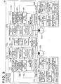
- FIG. 1 is a view that illustrates a configuration example of an MR system that uses a head mounted image-sensing display device according to the reference example.
- a head mounted image-sensing display device has a configuration that performs composite image generation processing including generation of a CG image and combination thereof with a real image.
- a configuration relating to generation of a composite image is not essential in a head mounted image-sensing display device, and the same processing may be implemented in an external device.
- a head mounted image-sensing display device 10 has a pair of optical units consisting of a right eye optical unit 110R and a left eye optical unit 110L that correspond to a right eye 100R and a left eye 100L of an observer, and a pair of video signal generating devices consisting of a right eye video signal generating device 20R and a left eye video signal generating device 20L.
- the optical units 110R and 110L have display units 13R and 13L, video input units 14R and 14L, image-sensing units 18R and 18L, captured image output units 1CR and 1CL, and image sensing parameter storage units 26R and 26L.
- the display units 13R and 13L function as a right eye display device that displays images for the right eye and a left eye display device that displays images for the left eye, respectively.
- the display units 13R and 13L have LCD modules 11R and 11L as display devices, and magnifying optical systems 12R and 12L that magnify display images at the LCD modules 11R and 11L.
- the LCD modules 11R and 11L have a liquid crystal panel such as a p-Si TFT or an LCOS (Liquid Crystal On Silicon), a peripheral circuit such as a driving circuit that drives the liquid crystal panel, and a light source such as a backlight or a front light (none of these are shown in the drawings).
- the LCD modules 11 R and 11L are disposed on an image plane of the magnifying optical systems 12R and 12L. Therefore, after an image that is rendered on the LCD modules 11R and 11L passes through an optical element in the magnifying optical systems 12R and 12L, the image is projected toward the right eye 100R and the left eye 100L of the observer wearing the head mounted image-sensing display device 10. As a result, the observer wearing the head mounted image-sensing display device 10 can observe the display image at the LCD modules 11R and 11L in a magnified state.
- the pair of image-sensing units 18R and 18L that are stereoscopic image-sensing devices have image sensors 19R and 19L such as a CMOS sensor or a CCD sensor, drive circuits (not shown) that drive the image sensors 19R and 19L, and image sensing lenses 1AR and 1AL.
- An optical image of an imaging object is formed by the image sensing lenses 1AR and 1AL on the image plane of the image sensors 19R and 19L. This optical image is converted into electrical signals in pixel units by a photoelectric conversion action of the image sensors 19R and 19L.
- the image-sensing units 18R and 18L sense and output stereoscopic images of a physical space.
- the image-sensing units 18R and 18L and the display units 13R and 13L are disposed so that the image sensing optical axis of the image-sensing units 18R and 18L and the optical axis on the projection side of the display units 13R and 13L substantially match.
- the image sensing parameter storage units 26R and 26L store parameters that define an optical axis or image sensing region of the image-sensing optical system of the image-sensing units 18R and 18L, such as an image sensing optical axis direction, a base line length, a principal point position, a focal distance, tilt values for each of the x, y, and z axes, and lens distortion correction data.
- the image sensing parameter storage units 26R and 26L are, for example, configured with a nonvolatile storage element, such as an EEPROM, whose contents are not erased even when the power is disconnected.
- the video signal generating devices 20R and 20L have image sensing parameters input units 23R and 23L, parallax image generating units 22R and 22L, video output units 21R and 21L, captured image input units 25R and 25L, and image computing units 27R and 27L, respectively.
- the video signal generating devices 20R and 20L generate and output video signals for the right eye and left eye using image sensing parameters and captured images from the right eye optical unit 110R and the left eye optical unit 110L.
- the captured image output units 1CR and 1CL execute electrical processing such as A/D conversion or amplification with respect to electrical signals that correspond to optical images of an imaging object that are output by the image sensors 19R and 19L, and supply the results to the captured image input units 25R and 25L of the video signal generating devices 20R and 20L.
- the image sensing parameters input units 23R and 23L read out the recording contents of the image sensing parameter storage units 26R and 26L and output the image sensing parameters that are read out to the parallax image generating units 22R and 22L.
- the parallax image generating units 22R and 22L generate images (parallax images) of a virtual object for the right eye and left eye based on the input image sensing parameters and three-dimensional model information of the virtual object.
- the image computing units 27R and 27L combine stereoscopic images from the captured image input units 25R and 25L with parallax images from the parallax image generating units 22R and 22L to generate composite images for the right eye and left eye.
- the composite images are supplied to the video input units 14R and 14L through the video output units 21R and 21L.
- the image sensing optical axis of the image-sensing units 18R and 18L and the optical axis on the projection side of the display units 13R and 13L are disposed so that they are substantially matching. Therefore, in the following description they are expressed simply as "optical axis" of an "optical unit”.
- FIG. 2 is a top view that illustrates an example of the positional relationship between an object in a physical space and optical axes 101R and 101L of the right eye optical unit 110R and the left eye optical unit 110L in a case in which assembly of the head mounted image-sensing display device 10 is performed correctly.
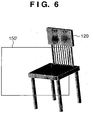
- the range that is captured by the image-sensing unit 18R is the portion surrounded by an image pickup region 150' in FIG. 6 , which is different to the original image pickup region 150.
- the virtual object is displayed at a position that deviates from the location at which the virtual object should originally be disposed.
- a misalignment also arises in the attachment angle in the vertical direction.
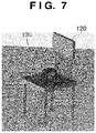
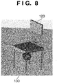
- a composite image is generated in which the virtual object 130 is embedded in the real object 120 or, as shown in FIG. 8 , a composite image is generated in which the virtual object 130 is suspended in mid-air.
- parallax information that is unique to the individual head mounted image-sensing display device 10 is stored as image sensing parameters in the image sensing parameter storage units 26R and 26L.
- the following kinds of information can be exemplified as parallax information according to the present reference example:
- the image sensing parameters may be fewer than the parameters exemplified here, or conversely, even more parameters may be stored.
- image sensing parameters are previously measured or calculated, and stored in the image sensing parameter storage units 26R and 26L as unique parameters of the optical units 110 of the head mounted image-sensing display device 10.
- the parallax image generating units 22R and 22L to generate parallax images of the virtual object 130 to be superimposed on actual images that are picked up by the image-sensing units 18R and 18L
- the unique image sensing parameters of the optical units 110 are read out from the image sensing parameter storage units 26R and 26L and used.
- the parallax image generating unit 22R generates a parallax image of the virtual object 130 in accordance with the image sensing parameters that are unique to the optical unit 110R, beginning with the actual convergence angle ⁇ '.
- three-dimensional model information information relating to shape, color, texture, three-dimensional position or the like
- image sensing parameters that are unique to the optical unit 110L are read out from the image sensing parameter storage unit 26L to generate a parallax image for the left eye using the image sensing parameters that are read out and the three-dimensional model information of the virtual object.
- the parallax images generated by the parallax image generating units 22R and 22L are transferred to the image computing units 27R and 27L.
- the parallax images are subjected to computational processing such as addition, multiplication, subtraction, or division with respect to the captured images of physical space picked up by the image-sensing units 18R and 18L to thereby generate composite images for the right eye and the left eye.
- the composite image for the right eye and the composite image for the left eye are transferred to the video output units 21R and 21L to be displayed on the LCD modules 11R and 11L of the display units 13R and 13L via the video input units 14R and 14L.
- the display contents of the LCD modules 11R and 11L are magnified by the magnifying optical systems 12R and 12L, the contents are projected onto the right eye 100R and left eye 100L of the observer wearing the head mounted image-sensing display device 10.
- Each image sensing parameter (camera parameter) stored in the image sensing parameter storage units 26R and 26L can be measured by an arbitrary method as long as the parameter values can be obtained at an acceptable accuracy.
- the parameters can be measured according to a method disclosed in Japanese Patent Laid-Open No. 2003-244521 . According to this method, a calibration pattern is picked up by the image-sensing units 18R and 18L, and the image-sensing units 18R and 18L calculate or estimate the camera parameters for the picked-up image by analyzing the picked-up image.
- processing to generate parallax images or composite images may be performed by an external device.
- the image computing units 27R and 27L and the parallax image generating units 22R and 22L in the video signal generating devices 20R and 20L can be implemented, for example, using software by executing a software program with a computer.
- the captured image output units 1CR and 1CL and the captured image input units 25R and 25L can be implemented with a wired communication interface that conforms to a standard such as USB or IEEE 1394 or a wireless communication interface that conforms to a standard such as IEEE 802.11x.
- the video input units 14R and 14L or the video output unit 21R and 21L can also be implemented by a similar interface.
- a head mounted image-sensing display device comprising an image-sensing device and a display device
- unique image sensing parameters are previously stored in an image-sensing optical system of the image-sensing device. It is therefore possible to know the conditions under which an image picked up by the image-sensing device is picked up.
- an effect is obtained whereby it is possible to generate a composite image with high alignment accuracy.
- this is advantageous when generating a composite image for providing an observer with a sense of virtual reality or mixed reality.
- FIG. 9 is a view that illustrates a configuration example of an MR system that uses a head mounted image-sensing display device according to a first embodiment of the present invention.
- elements that are the same as elements described according to the reference example are denoted by the same reference numerals and a detailed description of those elements is omitted.
- the image display system according to the present embodiment is the same as the MR system according to the reference example. Therefore, the fundamental configuration of a head mounted image-sensing display device 40 is common with that of the head mounted image-sensing display device 10. However, a difference from the reference example is that the head mounted image-sensing display device 40 is configured with the respective image-sensing optical systems and display optical systems on the left and right in an integrated state so that the base line length thereof is changeable. More specifically, the head mounted image-sensing display device 40 according to the present embodiment has, in addition to the configuration of the head mounted image-sensing display device 10, an eye width adjuster 17, a control unit 16, and an eye-width signal output unit 15.
- a base line length of the image-sensing optical systems and display optical systems that are integrated on the left and right sides, respectively, is acquired and calculated as eye width data in the manner described below.
- the control unit 16 reads in an eye-width setting value that is adjusted at the eye width adjuster 17 as an electrical signal, and passes the data to the eye-width signal output unit 15.
- the eye-width signal output unit 15 outputs a signal corresponding to the eye-width setting value to the image sensing parameters input units 23R and 23L.
- the image sensing parameters input units 23R and 23L read out from the image sensing parameter storage units 26R and 26L the image sensing parameters that correspond to the signal received from the eye-width signal output unit 15.
- various image sensing parameters associated with a plurality of base line lengths, respectively are previously measured and stored in the image sensing parameter storage units 26R and 26L, and thus image sensing parameters that are in accordance with the relevant base line length are read out.
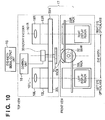
- FIG. 10 is a view illustrating a specific configuration example of the eye width adjuster 17.
- the eye width adjuster 17 has a pair of racks 33R and 33L, a gear 32, an adjustment knob 31, and a rotary encoder 30.
- the adjustment knob 31 and the gear 32 are fixed on the same shaft, and the rotary encoder 30 detects the amount of rotation of the shaft, that is, the rotation angle of the adjustment knob 31.
- One end of each rack in the pair of racks 33R and 33L is fixed to the right eye optical unit 110R and the left eye optical unit 110L, respectively, and the other end portion is configured so as to intermesh with the gear 32.
- the eye width adjuster 17 having this configuration, when the observer rotates the adjustment knob 31, the left and right optical units 110L and 110R are simultaneously moved in a parallel manner by the same amount in opposite directions to thereby change the base line length. More specifically, in FIG. 10 , when the adjustment knob 31 is rotated clockwise, the racks 33R and 33L move in directions that move the optical units 110R and 110L away from each.
- the rotation angle of the adjustment knob 31 (or the rotation angle of the gear 32) is detected by the rotary encoder 30.
- the rotary encoder 30 comprises an unshown internal click mechanism, and is configured to be capable of stopping at each predetermined rotation angle.
- corresponding image sensing parameters are measured for each predetermined angle that corresponds to a click mechanism of the rotary encoder 30.
- the measurement results are then stored in the image sensing parameter storage units 26R and 26L that are configured with a nonvolatile storage element such as an EEPROM.
- the image sensing parameters are:
- a plurality of sets of image sensing parameters that correspond to the rotation angle of the adjustment knob 31, in other words, the adjusted eye width, are stored in the image sensing parameter storage units 26R and 26L.
- a value corresponding to the current rotation angle of the shaft is determined based on a pulse that is output in accordance with rotation of the shaft by the rotary encoder 30.
- the control unit 16 outputs a value corresponding to the rotation angle to the eye-width signal output unit 15.
- the rotary encoder 30 employs a method capable of detecting the absolute amount of rotation of the rotating shaft, it is also possible to supply the output of a direct rotary encoder 30 to the eye-width signal output unit 15.
- the image sensing parameters input units 23R and 23L read out image sensing parameters corresponding to the value from the eye-width signal output unit 15 from the image sensing parameter storage units 26R and 26L.
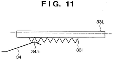
- a similar configuration can be obtained by providing a plurality of grooves 331 in the rack 33L and providing a spring 34 that energizes the rack 33L in the upward direction in the figure and that has a portion 34a that substantially corresponds to the groove 331. That is, by using the configuration shown in FIG. 11 , positions at which the optical units 110 stop can be provided in a stepwise condition by means of the intervals between the grooves 331.
- the position of the optical unit 110 may also be detected using a device other than the rotary encoder 30.
- a linear potentiometer comprising a variable resistor, or means that applies a magnetic field to an optical unit and detects a magnetic gradient may be utilized.
- image sensing parameters that correspond to a rotation angle (or eye width) other than a rotation angle (or eye width) measured at the time of adjustment at the production and assembly stage do not exist.
- image sensing parameters corresponding to rotation angles prior to and after the measured rotation angle it is possible to determine image sensing parameters that correspond to the actual rotation angle (or eye width).
- An arbitrary method is used by the image sensing parameters input units 23R and 23L to read out the image sensing parameters.
- a readout request is sent from the image sensing parameters input units 23R and 23L to the image sensing parameter storage units 26R and 26L.
- the image sensing parameter storage units 26R and 26L associate and store a plurality of rotation angles/eye widths and image sensing parameters. Therefore, by including a rotation angle/eye width in the request signal, image sensing parameters corresponding to the rotation angle in question can be read out from the image sensing parameter storage units 26R and 26L.
- parallax images of a virtual object are generated in accordance with the image sensing parameters that are read out from the image sensing parameters input units 23R and 23L.
- the image computing units 27R and 27L combine the parallax images from the parallax image generating units 22R and 22L with stereoscopic images from the captured image input units 25R and 25L to generate composite images.
- the image computing units 27R and 27L output the composite images to the video input units 14R and 14L of the head mounted image-sensing display device 40 via the video output units 21R and 21L.
- the invention can substantially eliminate parallax between the line of sight of the observer and the optical axes 101R and 101L of the image-sensing units 18R and 18L and the display units 13R and 13L.
- the image-sensing unit 18L may be disposed so that an optical axis 101L of the image-sensing unit 18L is positioned perpendicular to a plane including an optical axis (optical axis of left display unit 13L) 102L of the left eye of the observer and on a plane that includes the optical axis 102L of the left eye.
- the image-sensing unit 18R may be disposed so that an optical axis 101R of the image-sensing unit 18R is positioned perpendicular to a plane including an optical axis (optical axis of right display unit 13R) 102R of the right eye of the observer and on a plane that includes the optical axis 102R of the right eye.
- the present invention can also be applied to a head mounted image-sensing display device that automatically adjusts the eye width so that the observer's line of sight matches the optical axes of optical units by using, for example, line of sight detection technology.
- the mechanism for adjusting the eye width is different, and as long as it is possible to acquire a value corresponding to the value of the eye width (base line length) after adjustment, the first embodiment can be applied as it is.
- processing to generate parallax images or composite images may also be performed by an external device.
- identification information that can identify a head mounted image-sensing display device is stored, and the corresponding unique image sensing parameters can be associated therewith and stored in a management apparatus that is separate from the head mounted image-sensing display device.
- the identification information can then be acquired from the head mounted image-sensing display device connected to the MR system and the corresponding image sensing parameters can be acquired from the management apparatus to enable generation of composite images for the head mounted image-sensing display device in question.
- the image sensing parameters may be stored in any location.
Landscapes
- Engineering & Computer Science (AREA)
- Multimedia (AREA)
- Signal Processing (AREA)
- Testing, Inspecting, Measuring Of Stereoscopic Televisions And Televisions (AREA)
- Image Processing (AREA)
Description
- The present invention relates to a head mounted image-sensing display device, and more particularly to a head mounted image-sensing display device capable of performing a three-dimensional display by representing parallax images in both the left and right eye.
- The present invention also relates to a composite image generating apparatus that generates an image for display on this kind of head mounted image-sensing display device.
- In recent years, MR systems are known that allow an observer to experience mixed reality (MR) in which a virtual object seems to exist in a physical space. In an MR system, a composite image is generated by aligning and combining a real image of a physical space that is captured from the observer's observation point and a computer graphics (CG) image that represents a virtual object. The composite image is then represented to the observer.
- At this time, a head mounted display device (HMD) is generally utilized as a display apparatus that represents the composite image to the observer. Normally, an image-sensing device for capturing a physical space image of the observer's observation point is provided in a HMD that is used with an MR system. In a case in which the HMD is configured so as to be capable of representing independent video images in the left and right eyes, respectively, in many cases the image-sensing device will also have independent configurations for the right eye and the left eye. Hereunder, a HMD provided with an image-sensing device is referred to as a "head mounted image-sensing display device".
- In this kind of head mounted image-sensing display device, when the image sensing directions of a pair of image-sensing devices and the parallax of a pair of CG images that are combined with left and right images that are picked up by the image-sensing device do not match, the CG images that are observed appear unnatural and seamlessness with the physical space is not obtained. There is also a risk that the observer will feel a sense of fatigue while observing the unnatural image.
- To solve this problem, technology has been proposed that adjusts a display unit to conform to the eye width of the observer and generates a CG image including parallax in accordance with the adjustment amount thereof. This technology also attempts to substantially match the optical axis of an image-sensing optical system that corresponds to both the left and right eyes and the optical axis of a display optical system (Japanese Patent Laid-Open No.
2006-108868 - According to the aforementioned technology, by performing eye width adjustment, generating an image by taking into account the parallax thereof, and making the image sensing optical axis and the display optical axis match, it seems that an effect can be expected whereby the parallax of the virtual image and the actual image are matched. However, this effect can only be expected in a case in which, for a head mounted image-sensing display device, assembly is carried out so that the values for a base line length and an image sensing direction of an image-sensing device are in accordance with the design values.
- When assembly is performed with values that differ from the design values, ultimately a mismatch between the parallax of a real image and a CG image is not overcome. Therefore, there is still a risk that the observer wearing the head mounted image-sensing display device will feel a sense of discomfort and a sense of fatigue.
- Additionally,
JP 2006 285609 A - The present invention has been made in consideration of the above-described problem of the prior art. An object of the present invention is to provide a head mounted image-sensing display device that is capable of generating a composite image in which a difference in parallax between a picked up image of a physical space and an image of a virtual object is reduced.
- According to an aspect of the present invention, there is provided a head mounted image-sensing display device according to
claims 1 to 6. - According to another aspect of the present invention, there is provided a composite image generating system according to claims 7 or 8.
- Further features of the present invention will become apparent from the following description of exemplary embodiments with reference to the attached drawings. Further described is a reference example which is outside the scope of the invention as claimed here.
-
-
FIG. 1 is a view that illustrates a configuration example of an MR system that uses a head mounted image-sensing display device according to a reference example; -
FIG. 2 is a top view that illustrates an example of the positional relationship between an object in a physical space andoptical axes optical unit 110R and a left eyeoptical unit 110L in a case in which assembly of a head mounted image-sensing display device 10 is performed correctly; -
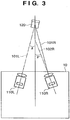
FIG. 3 is a top view that illustrates an example of the positional relationship between an object in a physical space andoptical axes optical unit 110R and a left eyeoptical unit 110L in a case in which assembly of a head mounted image-sensing display device 10 is not performed correctly; -
FIG. 4 is a view that illustrates an example of fusion between an image of a virtual object and an image of a physical space represented by the MR system according to the reference example; -
FIG. 5 is a view that illustrates an example of a region of a physical space that is picked up with the right eye optical unit shown inFIG. 2 ; -
FIG. 6 is a view that illustrates an example of a region of a physical space that is picked up with the right eye optical unit shown inFIG. 3 ; -
FIG. 7 andFIG. 8 are views that illustrate examples of a composite image in a case in which a parallax image is generated using design values irrespective of the fact that a convergence angle of an optical unit is out of alignment with a design value; -
FIG. 9 is a view that illustrates a configuration example of an MR system that uses a head mounted image-sensing display device according to a first embodiment of the present invention; -
FIG. 10 is a view that illustrates a configuration example of an eye width adjuster in the head mounted image-sensing display device according to the first embodiment of the present invention; -
FIG. 11 is a view that illustrates a separate example of a click mechanism for eye width adjustment in the head mounted image-sensing display device according to the first embodiment of the present invention; and -
FIG. 12 is a view that describes another arrangement example of an image-sensing unit in the head mounted image-sensing display device according to the first embodiment of the present invention. - Preferred embodiments of the present invention and the reference example will now be described in detail in accordance with the accompanying drawings.
-
FIG. 1 is a view that illustrates a configuration example of an MR system that uses a head mounted image-sensing display device according to the reference example. - In the present reference example, a case is described in which a head mounted image-sensing display device has a configuration that performs composite image generation processing including generation of a CG image and combination thereof with a real image. However, a configuration relating to generation of a composite image is not essential in a head mounted image-sensing display device, and the same processing may be implemented in an external device.
- A head mounted image-
sensing display device 10 has a pair of optical units consisting of a right eyeoptical unit 110R and a left eyeoptical unit 110L that correspond to aright eye 100R and aleft eye 100L of an observer, and a pair of video signal generating devices consisting of a right eye videosignal generating device 20R and a left eye videosignal generating device 20L. Theoptical units display units video input units sensing units parameter storage units display units display units LCD modules optical systems LCD modules - The
LCD modules LCD modules optical systems LCD modules optical systems right eye 100R and theleft eye 100L of the observer wearing the head mounted image-sensing display device 10. As a result, the observer wearing the head mounted image-sensing display device 10 can observe the display image at theLCD modules - The pair of image-
sensing units image sensors image sensors image sensors image sensors sensing units sensing units display units sensing units display units - The image sensing
parameter storage units sensing units parameter storage units - The video signal generating
devices parameters input units image generating units video output units image input units image computing units devices optical unit 110R and the left eyeoptical unit 110L. - The captured image output units 1CR and 1CL execute electrical processing such as A/D conversion or amplification with respect to electrical signals that correspond to optical images of an imaging object that are output by the
image sensors image input units signal generating devices - The image sensing
parameters input units parameter storage units image generating units - The parallax
image generating units - The
image computing units image input units image generating units video input units video output units - Operations to align a CG image and a real image in the head mounted image-
sensing display device 10 having the above configuration will now be described. - As described above, in the present reference example the image sensing optical axis of the image-sensing
units display units -
FIG. 2 is a top view that illustrates an example of the positional relationship between an object in a physical space andoptical axes optical unit 110R and the left eyeoptical unit 110L in a case in which assembly of the head mounted image-sensing display device 10 is performed correctly. - For this positional relationship, a case will be considered of combining an image in which a
virtual object 130 is mounted on aflat part 120a on areal object 120 in a physical space, as shown inFIG. 4 . As shown inFIG. 2 , it is assumed that both the left and rightoptical units optical axes optical unit 110R and the left eyeoptical unit 110L intersect at a point at a distance D from the image plane. - Further, when the right eye
optical unit 110R is attached at the correct convergence angle θ, it is assumed that a portion surrounded by animage pickup region 150 shown inFIG. 5 is captured by the image-sensingunit 18R. However, there are frequently cases in the production process in which the convergence angle deviates from the correct angle when an optical unit is attached. - For example, when the right eye
optical unit 110R is attached at a convergence angle θ' as shown inFIG. 3 , the range that is captured by the image-sensingunit 18R is the portion surrounded by an image pickup region 150' inFIG. 6 , which is different to the originalimage pickup region 150. - When information regarding the convergence angle θ' at which the right eye
optical unit 110R is actually attached can not be obtained, it is not possible to generate a CG image (parallax image) of thevirtual object 130 in which thevirtual object 130 is displayed in a condition in which it is correctly aligned with the physical space image that is picked up by the image-sensingunit 18R. - Thus, when the parallax images are generated according to the design value θ and combined with an actual image even though the actual convergence angle θ' deviates from the design value θ, as shown in
FIG. 8 , the virtual object is displayed at a position that deviates from the location at which the virtual object should originally be disposed. - Although a case is described here in which the attachment angle of an optical unit 110 is misaligned in the horizontal direction, in some cases a misalignment also arises in the attachment angle in the vertical direction. In that case, as shown in
FIG. 7 , a composite image is generated in which thevirtual object 130 is embedded in thereal object 120 or, as shown inFIG. 8 , a composite image is generated in which thevirtual object 130 is suspended in mid-air. - In contrast, according to the present reference example, parallax information that is unique to the individual head mounted image-
sensing display device 10 is stored as image sensing parameters in the image sensingparameter storage units - exact base line lengths of the image-sensing
units display units - the actual convergence angle θ;
- the focal distance, imaging angle of view, F number, and principal point position of image-sensing optical systems of the image-sensing
units - the optical axis directions of the optical units 110, and the like.
- In this connection, as long as it is possible to generate parallax images that have the same parallax as images picked up by the image-sensing
units - These image sensing parameters are previously measured or calculated, and stored in the image sensing
parameter storage units sensing display device 10. - Thereafter, when using the parallax
image generating units virtual object 130 to be superimposed on actual images that are picked up by the image-sensingunits parameter storage units - Thus, by generating parallax images using unique image combine sensing parameters of the optical units 110, images of the
virtual object 130 are generated that are correctly aligned with the actual images. Therefore, even in a case as shown, for example, inFIG. 3 , in which the convergence angle θ' of theoptical unit 110R differs from the design value θ, the parallaximage generating unit 22R generates a parallax image of thevirtual object 130 in accordance with the image sensing parameters that are unique to theoptical unit 110R, beginning with the actual convergence angle θ'. In this connection, it is assumed that three-dimensional model information (information relating to shape, color, texture, three-dimensional position or the like) of thevirtual object 130 is previously stored in the parallaximage generating units - Likewise, at the parallax
image generating unit 22L, image sensing parameters that are unique to theoptical unit 110L are read out from the image sensingparameter storage unit 26L to generate a parallax image for the left eye using the image sensing parameters that are read out and the three-dimensional model information of the virtual object. - The parallax images generated by the parallax
image generating units image computing units image computing units units - The composite image for the right eye and the composite image for the left eye are transferred to the
video output units LCD modules display units video input units LCD modules optical systems right eye 100R andleft eye 100L of the observer wearing the head mounted image-sensing display device 10. - Thus, according to the present reference example, it is possible to combine correctly aligned parallax images of the
virtual object 130 with images of physical space that are picked up by the image-sensingunits image computing units virtual object 130 is correctly disposed on thereal object 120 in a physical space. - Each image sensing parameter (camera parameter) stored in the image sensing
parameter storage units 2003-244521 units units - Although the configuration as described above according to the present reference example is one in which video
signal generating devices sensing display device 10, processing to generate parallax images or composite images may be performed by an external device. - At that time, the
image computing units image generating units signal generating devices image input units video input units video output unit - As described above, according to the present reference example, in a head mounted image-sensing display device comprising an image-sensing device and a display device, unique image sensing parameters are previously stored in an image-sensing optical system of the image-sensing device. It is therefore possible to know the conditions under which an image picked up by the image-sensing device is picked up. Thus, for example, when aligning an image of a virtual object with an image that is picked up with an image-sensing device to form a composite image, an effect is obtained whereby it is possible to generate a composite image with high alignment accuracy. In particular, this is advantageous when generating a composite image for providing an observer with a sense of virtual reality or mixed reality.
- The first embodiment of the present invention will now be described.
-
FIG. 9 is a view that illustrates a configuration example of an MR system that uses a head mounted image-sensing display device according to a first embodiment of the present invention. InFIG. 9 , elements that are the same as elements described according to the reference example are denoted by the same reference numerals and a detailed description of those elements is omitted. - The image display system according to the present embodiment is the same as the MR system according to the reference example. Therefore, the fundamental configuration of a head mounted image-
sensing display device 40 is common with that of the head mounted image-sensing display device 10. However, a difference from the reference example is that the head mounted image-sensing display device 40 is configured with the respective image-sensing optical systems and display optical systems on the left and right in an integrated state so that the base line length thereof is changeable. More specifically, the head mounted image-sensing display device 40 according to the present embodiment has, in addition to the configuration of the head mounted image-sensing display device 10, aneye width adjuster 17, acontrol unit 16, and an eye-widthsignal output unit 15. - By adopting this configuration, it is possible to adjust the base line length to match the eye width of each individual observer. Accordingly, by generating a composite image that takes into account the base line length after adjustment, it is possible to further reduce the burden of the observer.
- On the other hand, since the base line length is variable, if the method described according to the reference example in which previously measured fixed values are stored as image sensing parameters and then utilized is employed, it will not be possible to generate parallax images that reflect an adjusted eye width.
- Consequently, according to the present embodiment a base line length of the image-sensing optical systems and display optical systems that are integrated on the left and right sides, respectively, is acquired and calculated as eye width data in the manner described below.
- The
control unit 16 reads in an eye-width setting value that is adjusted at theeye width adjuster 17 as an electrical signal, and passes the data to the eye-widthsignal output unit 15. The eye-widthsignal output unit 15 outputs a signal corresponding to the eye-width setting value to the image sensingparameters input units - The image sensing
parameters input units parameter storage units signal output unit 15. According to the present embodiment, various image sensing parameters associated with a plurality of base line lengths, respectively, are previously measured and stored in the image sensingparameter storage units -
FIG. 10 is a view illustrating a specific configuration example of theeye width adjuster 17. - In
FIG. 10 , theeye width adjuster 17 has a pair ofracks gear 32, anadjustment knob 31, and arotary encoder 30. - The
adjustment knob 31 and thegear 32 are fixed on the same shaft, and therotary encoder 30 detects the amount of rotation of the shaft, that is, the rotation angle of theadjustment knob 31. One end of each rack in the pair ofracks optical unit 110R and the left eyeoptical unit 110L, respectively, and the other end portion is configured so as to intermesh with thegear 32. - According to the
eye width adjuster 17 having this configuration, when the observer rotates theadjustment knob 31, the left and rightoptical units FIG. 10 , when theadjustment knob 31 is rotated clockwise, theracks optical units - The rotation angle of the adjustment knob 31 (or the rotation angle of the gear 32) is detected by the
rotary encoder 30. Therotary encoder 30 comprises an unshown internal click mechanism, and is configured to be capable of stopping at each predetermined rotation angle. - At a time of adjustment during the stage of producing and assembling the head mounted image-
sensing display device 40 of the present embodiment, corresponding image sensing parameters are measured for each predetermined angle that corresponds to a click mechanism of therotary encoder 30. The measurement results are then stored in the image sensingparameter storage units - In the present embodiment, similarly to the reference example, the image sensing parameters are:
- the base line lengths of the image-sensing
units display units - the actual convergence angle θ;
- the focal distance, imaging angle of view, F number, and principal point position of image-sensing optical systems of the image-sensing
units - the optical axis direction of the optical unit 110, and the like.
- Taking these multiple parameters as one set, a plurality of sets of image sensing parameters that correspond to the rotation angle of the
adjustment knob 31, in other words, the adjusted eye width, are stored in the image sensingparameter storage units - At the
control unit 16 that is configured with a circuit using a microcomputer or the like, a value corresponding to the current rotation angle of the shaft, that is, a value corresponding to the eye width, is determined based on a pulse that is output in accordance with rotation of the shaft by therotary encoder 30. Thecontrol unit 16 outputs a value corresponding to the rotation angle to the eye-widthsignal output unit 15. In this connection, as long as therotary encoder 30 employs a method capable of detecting the absolute amount of rotation of the rotating shaft, it is also possible to supply the output of adirect rotary encoder 30 to the eye-widthsignal output unit 15. - The image sensing
parameters input units signal output unit 15 from the image sensingparameter storage units - In this connection, it is not necessary for the aforementioned click mechanism to be built into the
rotary encoder 30. For example, as shown inFIG. 11 , a similar configuration can be obtained by providing a plurality ofgrooves 331 in therack 33L and providing aspring 34 that energizes therack 33L in the upward direction in the figure and that has aportion 34a that substantially corresponds to thegroove 331. That is, by using the configuration shown inFIG. 11 , positions at which the optical units 110 stop can be provided in a stepwise condition by means of the intervals between thegrooves 331. - The position of the optical unit 110 may also be detected using a device other than the
rotary encoder 30. For example, a linear potentiometer comprising a variable resistor, or means that applies a magnetic field to an optical unit and detects a magnetic gradient may be utilized. - When a mechanism that regulates a stop position of the optical unit 110, such as a click function, is not provided, image sensing parameters that correspond to a rotation angle (or eye width) other than a rotation angle (or eye width) measured at the time of adjustment at the production and assembly stage do not exist. However, by interpolating image sensing parameters corresponding to rotation angles prior to and after the measured rotation angle it is possible to determine image sensing parameters that correspond to the actual rotation angle (or eye width).
- An arbitrary method is used by the image sensing
parameters input units parameters input units parameter storage units parameter storage units parameter storage units - At the parallax
image generating units parameters input units image computing units image generating units image input units image computing units video input units sensing display device 40 via thevideo output units - As a result, composite images in which parallax images are superimposed on captured images are displayed on the
LCD modules eye width adjuster 17 the invention can substantially eliminate parallax between the line of sight of the observer and theoptical axes units display units - It is therefore possible for the observer to visually recognize substantially the same state when wearing the head mounted image-
sensing display device 40 and when not wearing the head mounted image-sensing display device 40. Thus, the sense of fatigue of the observer can be controlled. - In this connection, as shown in
FIG. 12 , the image-sensingunit 18L may be disposed so that anoptical axis 101L of the image-sensingunit 18L is positioned perpendicular to a plane including an optical axis (optical axis ofleft display unit 13L) 102L of the left eye of the observer and on a plane that includes theoptical axis 102L of the left eye. Likewise, the image-sensingunit 18R may be disposed so that anoptical axis 101R of the image-sensingunit 18R is positioned perpendicular to a plane including an optical axis (optical axis ofright display unit 13R) 102R of the right eye of the observer and on a plane that includes theoptical axis 102R of the right eye. - According to the present embodiment, only a configuration in which the eye width is adjusted manually is described. However, the present invention can also be applied to a head mounted image-sensing display device that automatically adjusts the eye width so that the observer's line of sight matches the optical axes of optical units by using, for example, line of sight detection technology. In this case, only the mechanism for adjusting the eye width is different, and as long as it is possible to acquire a value corresponding to the value of the eye width (base line length) after adjustment, the first embodiment can be applied as it is.
- In the present embodiment, since parallax images are generated using image sensing parameters that correspond to an eye width that is adjusted by operating the
eye width adjuster 17, an effect of further reducing the burden of the observer can be achieved in addition to the effects of the reference example. - Although in the present embodiment, similarly to the reference example, a configuration in which the video
signal generating devices sensing display device 40 is described, processing to generate parallax images or composite images may also be performed by an external device. - In the above described embodiment, a configuration was described in which image sensing parameters that are unique to a head mounted image-sensing display device are stored in the head mounted image-sensing display device itself. However, as long as it is possible to acquire unique image sensing parameters corresponding to the individual head mounted image-sensing display device, it is not necessary that a storage location of image sensing parameters be inside the corresponding head mounted image-sensing display device.
- For example, when constructing an MR system utilizing a plurality of head mounted image-sensing display devices, identification information that can identify a head mounted image-sensing display device is stored, and the corresponding unique image sensing parameters can be associated therewith and stored in a management apparatus that is separate from the head mounted image-sensing display device.
- The identification information can then be acquired from the head mounted image-sensing display device connected to the MR system and the corresponding image sensing parameters can be acquired from the management apparatus to enable generation of composite images for the head mounted image-sensing display device in question.
- Thus, as long as a device that uses the image sensing parameters can acquire image sensing parameters corresponding to the relevant head mounted image-sensing display device, the image sensing parameters may be stored in any location.
- While the present invention has been described with reference to exemplary embodiments, it is to be understood that the invention is not limited to the disclosed exemplary embodiments but defined by the following claims.
- This application claims the benefit of Japanese Patent Application No.
2007-62481, filed on March 12, 2007
Claims (8)
- A head mounted image-sensing display device comprising:a pair of image-sensing means (18L, 18R) for stereoscopically capturing a physical space and outputting a pair of stereoscopic images;display means (13L, 13R, 20L, 20R) for displaying an image for a right eye and an image for a left eye based on said pair of stereoscopic images,wherein said display means includes left eye display means (13L) and right eye display means (13R), andwherein said left eye display means and one of said pair of image-sensing means (18L, 18R), and said right eye display means and the other of said pair of image-sensing means are integrated, respectively;non-volatile storage means (26L, 26R) storing image sensing parameters for generating parallax images of a virtual object to be superimposed on the pair of stereoscopic images;acquisition means (23L, 23R) for acquiring the image sensing parameters from said storage means (26L, 26R);generation means (22L, 22R) for generating the parallax images of the virtual object using the image sensing parameters that are acquired and three-dimensional model information; andimage combination means (27L, 27R) for combining the parallax images of the virtual object with the pair of stereoscopic images to output a resulting composite image to said display means;wherein the head mounted image-sensing display device further comprises an adjustment mechanism (31) for moving said left eye display means and the one of said pair of image-sensing means, and said right eye display means and the other of said pair of image-sensing means so as to change the base line length of said pair of image-sensing means;wherein said adjustment mechanism (31) comprises a regulating mechanism adapted to stop said movement at a plurality of predetermined stop positions; andwherein said image sensing parameters include parameters that represent a positional relationship of the pair of image sensing means and are previously measured at a time during producing and assembling the head mounted image-sensing display device for each of a plurality of base line lengths corresponding to said stop positions and stored in said storage means associated with the respective base line length as unique parameters corresponding to the individual head mounted image-sensing display device in order to take into account a difference between the actual and the design values of the image sensing parameters.
- The head mounted image-sensing display device according to claim 1, further comprising: an obtaining means for obtaining said image sensing parameters by analyzing a pair of stereoscopic images of a calibration pattern.
- The head mounted image-sensing display device according to claim 1 or 2, wherein the storage means is an EEPROM.
- The head mounted image-sensing display device according to any one of claims 1 to 3, wherein said left eye display means (13L) is disposed so that an optical axis of the left eye display means matches an optical axis of the one of said pair of image-sensing means (18L, 18R), and said right eye display means (13R) is disposed so that an optical axis of the right eye display means matches an optical axis of the other of said pair of image-sensing means (18L, 18R).
- The head mounted image-sensing display device according to any one of claims 1 to 4, further comprising:base line length acquisition means (16) for acquiring the base line length from the adjustment mechanism (31),wherein the acquisition means (23L, 23R) is adapted to acquire from said storage means the image sensing parameters that are associated with the base line length that is acquired.
- The head mounted image-sensing display device according to any one of claims 1 to 5, wherein the image sensing parameters include a convergence angle of each of the pair of image sensing means and a base line length of the pair of image sensing means.
- A composite image generating system, comprising a head mounted image-sensing display unit and an image generation unitthe head mounted image-sensing display unit comprising
a pair of image-sensing means (18L, 18R) for stereoscopically capturing a physical space and outputting a pair of stereoscopic images;
display means (13L, 13R, 20L, 20R) for displaying an image for a right eye and an image for a left eye based on said pair of stereoscopic images,
wherein said display means includes left eye display means (13L) and right eye display means (1 3R), and
wherein said left eye display means and one of said pair of image-sensing means (18L, 18R), and said right eye display means and the other of said pair of image-sensing means are integrated, respectively;captured image output means (1CR, 1CL) for outputting the pair of stereoscopic images to the image generation unit;composite image input means (14R, 14L) for receiving a composite image to be displayed by said display means from the image generation unit;an adjustment mechanism (31) for moving said left eye display means and the one of said pair of image-sensing means, and said right eye display means and the other of said pair of image-sensing means so as to change the base line length of said pair of image-sensing means, said adjustment mechanism (31) comprising a regulating mechanism adapted to stop said movement at a plurality of predetermined stop positions; andnon-volatile storage means (26L, 26R) storing image sensing parameters for generating parallax images of a virtual object to be superimposed on the pair of stereoscopic images;wherein said image sensing parameters include parameters that represent a positional relationship of the pair of image sensing means and are previously measured at a time during producing and assembling the head mounted image-sensing display device for each of a plurality of base line lengths corresponding to said stop positions and stored in said storage means associated with the respective base line length as unique parameters corresponding to the individual head mounted image-sensing display device in order to take into account a difference between the actual and the design values of the image sensing parameters; andthe image generation unit comprising
acquisition means (23L, 23R) for acquiring the image sensing parameters from said storage means (26L, 26R);
generation means (22L, 22R) for generating the parallax images of the virtual object using the image sensing parameters that are acquired and three-dimensional model information;
captured image input means (25R, 25L) for receiving the pair of stereoscopic images from the head mounted image sensing display unit;
image combination means (27L, 27R) for combining the parallax images of the virtual object with the pair of stereoscopic images to obtain a composite image; and
composite image output means (21 R, 21L) for outputting the composite image to the head mounted image sensing display unit. - A composite image generating system, comprising a head mounted image-sensing display unit, a storage unit, and an image generation unit,the head mounted image-sensing display unit comprising
a pair of image-sensing means (18L, 18R) for stereoscopically capturing a physical space and outputting a pair of stereoscopic images;
display means (13L, 13R, 20L, 20R) for displaying an image for a right eye and an image for a left eye based on said pair of stereoscopic images;
an adjustment mechanism (31) for moving said left eye display means and the one of said pair of image-sensing means, and said right eye display means and the other of said pair of image-sensing means so as to change the base line length of said pair of image-sensing means, said adjustment mechanism (31) comprising a regulating mechanism adapted to stop said movement at a plurality of predetermined stop positions;
captured image output means (1CR, 1CL) for outputting the pair of stereoscopic images to the image generation unit;
composite image input means (14R, 14L) for receiving a composite image to be displayed by said display means from the image generation unit; and
identification means for providing identification information of the head mounted image-sensing display unit;
wherein said display means includes left eye display means (13L) and right eye display means (1 3R), and
wherein said left eye display means and one of said pair of image-sensing means (18L, 18R), and said right eye display means and the other of said pair of image-sensing means are integrated, respectively;the storage unit storing, associated with the identification information, image sensing parameters for generating parallax images of a virtual object to be superimposed on said pair of stereoscopic images, wherein said image sensing parameters include parameters that represent a positional relationship of the pair of image sensing means and are previously measured at a time during producing and assembling the head mounted image-sensing display device for each of a plurality of base line lengths corresponding to said stop positions and stored in said storage means associated with the respective base line length as unique parameters corresponding to the individual head mounted image-sensing display device in order to take into account a difference between the actual and the design values of the image sensing parameters; andthe image generation unit comprising
acquisition means (23L, 23R) for acquiring the image sensing parameters from said storage unit;
generation means (22L, 22R) for generating the parallax images of the virtual object using the image sensing parameters that are acquired and three-dimensional model information;
captured image input means (25R, 25L) for receiving the pair of stereoscopic images from the head mounted image sensing display unit;
image combination means (27L, 27R) for combining the parallax images of the virtual object with the pair of stereoscopic images to obtain a composite image; and
composite image output means (21R, 21L) for outputting the composite image to the head mounted image sensing display unit.
Applications Claiming Priority (3)
| Application Number | Priority Date | Filing Date | Title |
|---|---|---|---|
| JP2007062481A JP5507797B2 (en) | 2007-03-12 | 2007-03-12 | Head-mounted imaging display device and image generation device |
| EP20080722078 EP2123058B1 (en) | 2007-03-12 | 2008-03-07 | Head mounted image-sensing display device and composite image generating apparatus |
| PCT/JP2008/054681 WO2008114704A1 (en) | 2007-03-12 | 2008-03-07 | Head mounted image-sensing display device and composite image generating apparatus |
Related Parent Applications (2)
| Application Number | Title | Priority Date | Filing Date |
|---|---|---|---|
| EP20080722078 Division EP2123058B1 (en) | 2007-03-12 | 2008-03-07 | Head mounted image-sensing display device and composite image generating apparatus |
| EP20080722078 Division-Into EP2123058B1 (en) | 2007-03-12 | 2008-03-07 | Head mounted image-sensing display device and composite image generating apparatus |
Publications (2)
| Publication Number | Publication Date |
|---|---|
| EP2911391A1 EP2911391A1 (en) | 2015-08-26 |
| EP2911391B1 true EP2911391B1 (en) | 2020-05-27 |
Family
ID=39765812
Family Applications (2)
| Application Number | Title | Priority Date | Filing Date |
|---|---|---|---|
| EP20080722078 Active EP2123058B1 (en) | 2007-03-12 | 2008-03-07 | Head mounted image-sensing display device and composite image generating apparatus |
| EP15000686.4A Not-in-force EP2911391B1 (en) | 2007-03-12 | 2008-03-07 | Head mounted image-sensing display device and composite image generating apparatus |
Family Applications Before (1)
| Application Number | Title | Priority Date | Filing Date |
|---|---|---|---|
| EP20080722078 Active EP2123058B1 (en) | 2007-03-12 | 2008-03-07 | Head mounted image-sensing display device and composite image generating apparatus |
Country Status (5)
| Country | Link |
|---|---|
| US (2) | US8717420B2 (en) |
| EP (2) | EP2123058B1 (en) |
| JP (1) | JP5507797B2 (en) |
| CN (1) | CN101641963B (en) |
| WO (1) | WO2008114704A1 (en) |
Families Citing this family (35)
| Publication number | Priority date | Publication date | Assignee | Title |
|---|---|---|---|---|
| JP5067850B2 (en) * | 2007-08-02 | 2012-11-07 | キヤノン株式会社 | System, head-mounted display device, and control method thereof |
| JP2010124191A (en) * | 2008-11-19 | 2010-06-03 | Canon Inc | Video image display device |
| EP2401865B1 (en) * | 2009-02-27 | 2020-07-15 | Foundation Productions, Llc | Headset-based telecommunications platform |
| WO2010141870A1 (en) * | 2009-06-04 | 2010-12-09 | Kopin Corporation | 3d video processor integrated with head mounted display |
| JP5521913B2 (en) * | 2009-10-28 | 2014-06-18 | ソニー株式会社 | Image processing apparatus, image processing method, and program |
| JP2011233958A (en) * | 2010-04-23 | 2011-11-17 | Olympus Corp | Head-mounted image display device |
| JP2012109934A (en) * | 2010-10-19 | 2012-06-07 | Panasonic Corp | Stereoscopic image display device |
| JP2012129768A (en) * | 2010-12-15 | 2012-07-05 | Seiko Epson Corp | Document camera, document camera control method, program, and display processing system |
| EP2687904B1 (en) * | 2011-03-18 | 2017-02-15 | FUJIFILM Corporation | Lens system for capturing stereoscopic images |
| CN102810099B (en) * | 2011-05-31 | 2018-04-27 | 中兴通讯股份有限公司 | The storage method and device of augmented reality view |
| JP2013044913A (en) * | 2011-08-24 | 2013-03-04 | Sony Corp | Display device and display control method |
| JP2013085705A (en) * | 2011-10-18 | 2013-05-13 | Canon Inc | Acoustic wave acquiring apparatus and control method thereof |
| JP6021328B2 (en) * | 2011-12-22 | 2016-11-09 | キヤノン株式会社 | Information processing apparatus, information processing apparatus control method, and program |
| RU2015145510A (en) | 2013-03-26 | 2017-05-03 | Сейко Эпсон Корпорейшн | CRIMINAL DISPLAY DEVICE, METHOD FOR MANAGEMENT OF THE CRIMINAL DISPLAY DEVICE AND DISPLAY SYSTEM |
| CN103500446B (en) * | 2013-08-28 | 2016-10-26 | 成都理想境界科技有限公司 | A kind of head-wearing display device |
| CN103605199B (en) * | 2013-08-30 | 2016-09-28 | 北京智谷睿拓技术服务有限公司 | Imaging device and method |
| US9299007B2 (en) * | 2014-01-28 | 2016-03-29 | Ncr Corporation | Methods and apparatus for item identification using brightness compensation |
| CN104144335B (en) * | 2014-07-09 | 2017-02-01 | 歌尔科技有限公司 | Head-wearing type visual device and video system |
| JP6438694B2 (en) * | 2014-07-09 | 2018-12-19 | 日本放送協会 | 3D image display device and image generation program |
| US10152119B2 (en) * | 2014-12-11 | 2018-12-11 | Htc Corporation | Head-mounted display apparatus and calibration method thereof |
| US10222619B2 (en) * | 2015-07-12 | 2019-03-05 | Steven Sounyoung Yu | Head-worn image display apparatus for stereoscopic microsurgery |
| US20170115489A1 (en) * | 2015-10-26 | 2017-04-27 | Xinda Hu | Head mounted display device with multiple segment display and optics |
| CN106680996A (en) * | 2015-11-05 | 2017-05-17 | 丰唐物联技术(深圳)有限公司 | Display method and display control system of head-mounted virtual reality display |
| CN106254852A (en) * | 2015-11-10 | 2016-12-21 | 深圳市拓丰源电子科技有限公司 | Image capture method, image-capturing apparatus and virtual reality strengthen system |
| CN106408666B (en) * | 2016-08-31 | 2019-06-21 | 重庆玩艺互动科技有限公司 | Mixed reality reality border demenstration method |
| US10299880B2 (en) | 2017-04-24 | 2019-05-28 | Truevision Systems, Inc. | Stereoscopic visualization camera and platform |
| US10917543B2 (en) | 2017-04-24 | 2021-02-09 | Alcon Inc. | Stereoscopic visualization camera and integrated robotics platform |
| US11083537B2 (en) | 2017-04-24 | 2021-08-10 | Alcon Inc. | Stereoscopic camera with fluorescence visualization |
| US11184559B2 (en) | 2017-08-02 | 2021-11-23 | Sony Corporation | Image processing device, image processing method, and imaging device |
| CN109725418B (en) * | 2017-10-30 | 2020-10-16 | 华为技术有限公司 | Display device, method and device for adjusting image presentation of display device |
| JP2020048017A (en) * | 2018-09-18 | 2020-03-26 | ソニー株式会社 | Display control unit and display control method, and recording medium |
| CN111654688B (en) * | 2020-05-29 | 2022-03-29 | 亮风台(上海)信息科技有限公司 | Method and equipment for acquiring target control parameters |
| CN111866493B (en) * | 2020-06-09 | 2022-01-28 | 青岛小鸟看看科技有限公司 | Image correction method, device and equipment based on head-mounted display equipment |
| US12044865B2 (en) * | 2022-04-16 | 2024-07-23 | Kamil Podhola | Liquid crystal system display for stereovision |
| CN115174886A (en) * | 2022-08-25 | 2022-10-11 | 吉林大学 | Mobile phone lens supporting stereoscopic virtual reality and augmented reality and display method |
Citations (2)
| Publication number | Priority date | Publication date | Assignee | Title |
|---|---|---|---|---|
| JPH0787385A (en) * | 1993-09-10 | 1995-03-31 | Canon Inc | Image pickup device |
| EP1686554A2 (en) * | 2005-01-31 | 2006-08-02 | Canon Kabushiki Kaisha | Virtual space generating system, image processing apparatus and information processing method |
Family Cites Families (26)
| Publication number | Priority date | Publication date | Assignee | Title |
|---|---|---|---|---|
| EP0644701B1 (en) | 1993-09-20 | 1999-12-01 | Canon Kabushiki Kaisha | Image taking and/or displaying system |
| US5978015A (en) * | 1994-10-13 | 1999-11-02 | Minolta Co., Ltd. | Stereoscopic system with convergence and dioptric power adjustments according to object distance |
| US6640004B2 (en) * | 1995-07-28 | 2003-10-28 | Canon Kabushiki Kaisha | Image sensing and image processing apparatuses |
| JP3962115B2 (en) * | 1996-11-08 | 2007-08-22 | オリンパス株式会社 | Video observation device |
| US6762794B1 (en) * | 1997-12-03 | 2004-07-13 | Canon Kabushiki Kaisha | Image pick-up apparatus for stereoscope |
| US6249311B1 (en) * | 1998-02-24 | 2001-06-19 | Inframetrics Inc. | Lens assembly with incorporated memory module |
| US20040108971A1 (en) * | 1998-04-09 | 2004-06-10 | Digilens, Inc. | Method of and apparatus for viewing an image |
| US6464363B1 (en) * | 1999-03-17 | 2002-10-15 | Olympus Optical Co., Ltd. | Variable mirror, optical apparatus and decentered optical system which include variable mirror, variable-optical characteristic optical element or combination thereof |
| EP1083755A3 (en) * | 1999-09-07 | 2003-11-12 | Canon Kabushiki Kaisha | Image input apparatus and image display apparatus |
| JP3793100B2 (en) * | 2002-02-14 | 2006-07-05 | キヤノン株式会社 | Information processing method, apparatus, and recording medium |
| JP4193990B2 (en) * | 2002-03-22 | 2008-12-10 | ディーリング,マイケル,エフ. | Scalable high-performance 3D graphics |
| US7224382B2 (en) * | 2002-04-12 | 2007-05-29 | Image Masters, Inc. | Immersive imaging system |
| US7427996B2 (en) * | 2002-10-16 | 2008-09-23 | Canon Kabushiki Kaisha | Image processing apparatus and image processing method |
| CN2711762Y (en) * | 2004-04-28 | 2005-07-20 | 陆静麟 | Stereopsis display screen |
| EP1754382B1 (en) * | 2004-05-26 | 2010-09-01 | Tibor Balogh | Method and apparatus for generating 3d images |
| US7952594B2 (en) * | 2004-05-27 | 2011-05-31 | Canon Kabushiki Kaisha | Information processing method, information processing apparatus, and image sensing apparatus |
| EP1779081A4 (en) * | 2004-08-03 | 2012-05-09 | Silverbrook Res Pty Ltd | Electronic stylus |
| JP4965800B2 (en) * | 2004-10-01 | 2012-07-04 | キヤノン株式会社 | Image display system |
| US7643672B2 (en) * | 2004-10-21 | 2010-01-05 | Kazunari Era | Image processing apparatus, image pickup device and program therefor |
| CN1304931C (en) * | 2005-01-27 | 2007-03-14 | 北京理工大学 | Head carried stereo vision hand gesture identifying device |
| JP2006285609A (en) * | 2005-03-31 | 2006-10-19 | Canon Inc | Image processing method, image processor |
| US7868904B2 (en) * | 2005-04-01 | 2011-01-11 | Canon Kabushiki Kaisha | Image processing method and image processing apparatus |
| CN100512455C (en) * | 2005-08-05 | 2009-07-08 | 庞维克 | Method and device for stereoscopic imaging |
| US9270976B2 (en) * | 2005-11-02 | 2016-02-23 | Exelis Inc. | Multi-user stereoscopic 3-D panoramic vision system and method |
| IL174170A (en) * | 2006-03-08 | 2015-02-26 | Abraham Aharoni | Device and method for binocular alignment |
| JP4926817B2 (en) * | 2006-08-11 | 2012-05-09 | キヤノン株式会社 | Index arrangement information measuring apparatus and method |
-
2007
- 2007-03-12 JP JP2007062481A patent/JP5507797B2/en not_active Expired - Fee Related
-
2008
- 2008-03-07 EP EP20080722078 patent/EP2123058B1/en active Active
- 2008-03-07 WO PCT/JP2008/054681 patent/WO2008114704A1/en active Application Filing
- 2008-03-07 US US12/523,563 patent/US8717420B2/en active Active
- 2008-03-07 EP EP15000686.4A patent/EP2911391B1/en not_active Not-in-force
- 2008-03-07 CN CN2008800077839A patent/CN101641963B/en active Active
-
2014
- 2014-03-18 US US14/217,747 patent/US20140198191A1/en not_active Abandoned
Patent Citations (2)
| Publication number | Priority date | Publication date | Assignee | Title |
|---|---|---|---|---|
| JPH0787385A (en) * | 1993-09-10 | 1995-03-31 | Canon Inc | Image pickup device |
| EP1686554A2 (en) * | 2005-01-31 | 2006-08-02 | Canon Kabushiki Kaisha | Virtual space generating system, image processing apparatus and information processing method |
Also Published As
| Publication number | Publication date |
|---|---|
| JP2008227865A (en) | 2008-09-25 |
| EP2123058A4 (en) | 2012-10-17 |
| EP2911391A1 (en) | 2015-08-26 |
| US20140198191A1 (en) | 2014-07-17 |
| EP2123058A1 (en) | 2009-11-25 |
| CN101641963B (en) | 2012-01-11 |
| CN101641963A (en) | 2010-02-03 |
| US8717420B2 (en) | 2014-05-06 |
| EP2123058B1 (en) | 2015-05-13 |
| US20100026787A1 (en) | 2010-02-04 |
| JP5507797B2 (en) | 2014-05-28 |
| WO2008114704A1 (en) | 2008-09-25 |
Similar Documents
| Publication | Publication Date | Title |
|---|---|---|
| EP2911391B1 (en) | Head mounted image-sensing display device and composite image generating apparatus | |
| US11223820B2 (en) | Augmented reality displays with active alignment and corresponding methods | |
| US10869024B2 (en) | Augmented reality displays with active alignment and corresponding methods | |
| US10825424B2 (en) | Homography transformation matrices based temperature calibration of a viewing system | |
| US10591735B2 (en) | Head-mounted display device and image display system | |
| JP4965800B2 (en) | Image display system | |
| US8208008B2 (en) | Apparatus, method, and program for displaying stereoscopic images | |
| CN103947199A (en) | Image processing device, three-dimensional image display device, image processing method and image processing program | |
| JP2001211403A (en) | Head mount display device and head mount display system | |
| WO2013043695A1 (en) | System and method for improving methods of manufacturing stereoscopic image sensors | |
| JP4432462B2 (en) | Imaging apparatus and method, imaging system | |
| US20130093855A1 (en) | Parallel axis stereoscopic camera | |
| JP2012014019A (en) | Imaging device and control method thereof | |
| US10659752B2 (en) | System for the stereoscopic visualization of an object region | |
| JP2010124191A (en) | Video image display device | |
| JP5767720B2 (en) | Head-mounted display device, virtual image generation device, system having the same, and control method | |
| CN103430095A (en) | Lens system for capturing stereoscopic images | |
| JP2006340017A (en) | Device and method for stereoscopic video image display | |
| KR101293115B1 (en) | Method for aligning optical axes of stereoscopic camera and the stereoscopic camera, program storing medium for executing the method | |
| KR101864450B1 (en) | Camera module and method for compensating image of the same | |
| US12058304B2 (en) | Augmented reality display device and method | |
| JP2023102773A (en) | Device and method to calibrate parallax optical element for temperature change | |
| CN115509007A (en) | Augmented reality display device and method |
Legal Events
| Date | Code | Title | Description |
|---|---|---|---|
| PUAI | Public reference made under article 153(3) epc to a published international application that has entered the european phase |
Free format text: ORIGINAL CODE: 0009012 |
|
| AC | Divisional application: reference to earlier application |
Ref document number: 2123058 Country of ref document: EP Kind code of ref document: P |
|
| AK | Designated contracting states |
Kind code of ref document: A1 Designated state(s): AT BE BG CH CY CZ DE DK EE ES FI FR GB GR HR HU IE IS IT LI LT LU LV MC MT NL NO PL PT RO SE SI SK TR |
|
| 17P | Request for examination filed |
Effective date: 20160226 |
|
| RBV | Designated contracting states (corrected) |
Designated state(s): AT BE BG CH CY CZ DE DK EE ES FI FR GB GR HR HU IE IS IT LI LT LU LV MC MT NL NO PL PT RO SE SI SK TR |
|
| STAA | Information on the status of an ep patent application or granted ep patent |
Free format text: STATUS: EXAMINATION IS IN PROGRESS |
|
| 17Q | First examination report despatched |
Effective date: 20171016 |
|
| REG | Reference to a national code |
Ref country code: DE Ref legal event code: R079 Ref document number: 602008062784 Country of ref document: DE Free format text: PREVIOUS MAIN CLASS: H04N0013000000 Ipc: H04N0013344000 |
|
| RIC1 | Information provided on ipc code assigned before grant |
Ipc: H04N 13/327 20180101ALI20191018BHEP Ipc: H04N 13/344 20180101AFI20191018BHEP Ipc: H04N 13/332 20180101ALI20191018BHEP |
|
| GRAP | Despatch of communication of intention to grant a patent |
Free format text: ORIGINAL CODE: EPIDOSNIGR1 |
|
| STAA | Information on the status of an ep patent application or granted ep patent |
Free format text: STATUS: GRANT OF PATENT IS INTENDED |
|
| INTG | Intention to grant announced |
Effective date: 20191220 |
|
| GRAS | Grant fee paid |
Free format text: ORIGINAL CODE: EPIDOSNIGR3 |
|
| GRAA | (expected) grant |
Free format text: ORIGINAL CODE: 0009210 |
|
| STAA | Information on the status of an ep patent application or granted ep patent |
Free format text: STATUS: THE PATENT HAS BEEN GRANTED |
|
| AC | Divisional application: reference to earlier application |
Ref document number: 2123058 Country of ref document: EP Kind code of ref document: P |
|
| AK | Designated contracting states |
Kind code of ref document: B1 Designated state(s): AT BE BG CH CY CZ DE DK EE ES FI FR GB GR HR HU IE IS IT LI LT LU LV MC MT NL NO PL PT RO SE SI SK TR |
|
| RAP1 | Party data changed (applicant data changed or rights of an application transferred) |
Owner name: CANON KABUSHIKI KAISHA |
|
| REG | Reference to a national code |
Ref country code: GB Ref legal event code: FG4D |
|
| REG | Reference to a national code |
Ref country code: CH Ref legal event code: EP |
|
| REG | Reference to a national code |
Ref country code: AT Ref legal event code: REF Ref document number: 1275805 Country of ref document: AT Kind code of ref document: T Effective date: 20200615 |
|
| REG | Reference to a national code |
Ref country code: DE Ref legal event code: R096 Ref document number: 602008062784 Country of ref document: DE |
|
| REG | Reference to a national code |
Ref country code: LT Ref legal event code: MG4D |
|
| PG25 | Lapsed in a contracting state [announced via postgrant information from national office to epo] |
Ref country code: LT Free format text: LAPSE BECAUSE OF FAILURE TO SUBMIT A TRANSLATION OF THE DESCRIPTION OR TO PAY THE FEE WITHIN THE PRESCRIBED TIME-LIMIT Effective date: 20200527 Ref country code: NO Free format text: LAPSE BECAUSE OF FAILURE TO SUBMIT A TRANSLATION OF THE DESCRIPTION OR TO PAY THE FEE WITHIN THE PRESCRIBED TIME-LIMIT Effective date: 20200827 Ref country code: GR Free format text: LAPSE BECAUSE OF FAILURE TO SUBMIT A TRANSLATION OF THE DESCRIPTION OR TO PAY THE FEE WITHIN THE PRESCRIBED TIME-LIMIT Effective date: 20200828 Ref country code: SE Free format text: LAPSE BECAUSE OF FAILURE TO SUBMIT A TRANSLATION OF THE DESCRIPTION OR TO PAY THE FEE WITHIN THE PRESCRIBED TIME-LIMIT Effective date: 20200527 Ref country code: PT Free format text: LAPSE BECAUSE OF FAILURE TO SUBMIT A TRANSLATION OF THE DESCRIPTION OR TO PAY THE FEE WITHIN THE PRESCRIBED TIME-LIMIT Effective date: 20200928 Ref country code: IS Free format text: LAPSE BECAUSE OF FAILURE TO SUBMIT A TRANSLATION OF THE DESCRIPTION OR TO PAY THE FEE WITHIN THE PRESCRIBED TIME-LIMIT Effective date: 20200927 Ref country code: FI Free format text: LAPSE BECAUSE OF FAILURE TO SUBMIT A TRANSLATION OF THE DESCRIPTION OR TO PAY THE FEE WITHIN THE PRESCRIBED TIME-LIMIT Effective date: 20200527 |
|
| REG | Reference to a national code |
Ref country code: NL Ref legal event code: MP Effective date: 20200527 |
|
| PG25 | Lapsed in a contracting state [announced via postgrant information from national office to epo] |
Ref country code: HR Free format text: LAPSE BECAUSE OF FAILURE TO SUBMIT A TRANSLATION OF THE DESCRIPTION OR TO PAY THE FEE WITHIN THE PRESCRIBED TIME-LIMIT Effective date: 20200527 Ref country code: LV Free format text: LAPSE BECAUSE OF FAILURE TO SUBMIT A TRANSLATION OF THE DESCRIPTION OR TO PAY THE FEE WITHIN THE PRESCRIBED TIME-LIMIT Effective date: 20200527 Ref country code: BG Free format text: LAPSE BECAUSE OF FAILURE TO SUBMIT A TRANSLATION OF THE DESCRIPTION OR TO PAY THE FEE WITHIN THE PRESCRIBED TIME-LIMIT Effective date: 20200827 |
|
| REG | Reference to a national code |
Ref country code: AT Ref legal event code: MK05 Ref document number: 1275805 Country of ref document: AT Kind code of ref document: T Effective date: 20200527 |
|
| PG25 | Lapsed in a contracting state [announced via postgrant information from national office to epo] |
Ref country code: NL Free format text: LAPSE BECAUSE OF FAILURE TO SUBMIT A TRANSLATION OF THE DESCRIPTION OR TO PAY THE FEE WITHIN THE PRESCRIBED TIME-LIMIT Effective date: 20200527 |
|
| PG25 | Lapsed in a contracting state [announced via postgrant information from national office to epo] |
Ref country code: EE Free format text: LAPSE BECAUSE OF FAILURE TO SUBMIT A TRANSLATION OF THE DESCRIPTION OR TO PAY THE FEE WITHIN THE PRESCRIBED TIME-LIMIT Effective date: 20200527 Ref country code: RO Free format text: LAPSE BECAUSE OF FAILURE TO SUBMIT A TRANSLATION OF THE DESCRIPTION OR TO PAY THE FEE WITHIN THE PRESCRIBED TIME-LIMIT Effective date: 20200527 Ref country code: ES Free format text: LAPSE BECAUSE OF FAILURE TO SUBMIT A TRANSLATION OF THE DESCRIPTION OR TO PAY THE FEE WITHIN THE PRESCRIBED TIME-LIMIT Effective date: 20200527 Ref country code: CZ Free format text: LAPSE BECAUSE OF FAILURE TO SUBMIT A TRANSLATION OF THE DESCRIPTION OR TO PAY THE FEE WITHIN THE PRESCRIBED TIME-LIMIT Effective date: 20200527 Ref country code: IT Free format text: LAPSE BECAUSE OF FAILURE TO SUBMIT A TRANSLATION OF THE DESCRIPTION OR TO PAY THE FEE WITHIN THE PRESCRIBED TIME-LIMIT Effective date: 20200527 Ref country code: AT Free format text: LAPSE BECAUSE OF FAILURE TO SUBMIT A TRANSLATION OF THE DESCRIPTION OR TO PAY THE FEE WITHIN THE PRESCRIBED TIME-LIMIT Effective date: 20200527 Ref country code: DK Free format text: LAPSE BECAUSE OF FAILURE TO SUBMIT A TRANSLATION OF THE DESCRIPTION OR TO PAY THE FEE WITHIN THE PRESCRIBED TIME-LIMIT Effective date: 20200527 |
|
| PG25 | Lapsed in a contracting state [announced via postgrant information from national office to epo] |
Ref country code: SK Free format text: LAPSE BECAUSE OF FAILURE TO SUBMIT A TRANSLATION OF THE DESCRIPTION OR TO PAY THE FEE WITHIN THE PRESCRIBED TIME-LIMIT Effective date: 20200527 Ref country code: PL Free format text: LAPSE BECAUSE OF FAILURE TO SUBMIT A TRANSLATION OF THE DESCRIPTION OR TO PAY THE FEE WITHIN THE PRESCRIBED TIME-LIMIT Effective date: 20200527 |
|
| REG | Reference to a national code |
Ref country code: DE Ref legal event code: R097 Ref document number: 602008062784 Country of ref document: DE |
|
| PLBE | No opposition filed within time limit |
Free format text: ORIGINAL CODE: 0009261 |
|
| STAA | Information on the status of an ep patent application or granted ep patent |
Free format text: STATUS: NO OPPOSITION FILED WITHIN TIME LIMIT |
|
| 26N | No opposition filed |
Effective date: 20210302 |
|
| PG25 | Lapsed in a contracting state [announced via postgrant information from national office to epo] |
Ref country code: SI Free format text: LAPSE BECAUSE OF FAILURE TO SUBMIT A TRANSLATION OF THE DESCRIPTION OR TO PAY THE FEE WITHIN THE PRESCRIBED TIME-LIMIT Effective date: 20200527 |
|
| PGFP | Annual fee paid to national office [announced via postgrant information from national office to epo] |
Ref country code: GB Payment date: 20210219 Year of fee payment: 14 |
|
| REG | Reference to a national code |
Ref country code: DE Ref legal event code: R119 Ref document number: 602008062784 Country of ref document: DE |
|
| PG25 | Lapsed in a contracting state [announced via postgrant information from national office to epo] |
Ref country code: MC Free format text: LAPSE BECAUSE OF FAILURE TO SUBMIT A TRANSLATION OF THE DESCRIPTION OR TO PAY THE FEE WITHIN THE PRESCRIBED TIME-LIMIT Effective date: 20200527 |
|
| REG | Reference to a national code |
Ref country code: CH Ref legal event code: PL |
|
| REG | Reference to a national code |
Ref country code: BE Ref legal event code: MM Effective date: 20210331 |
|
| PG25 | Lapsed in a contracting state [announced via postgrant information from national office to epo] |
Ref country code: CH Free format text: LAPSE BECAUSE OF NON-PAYMENT OF DUE FEES Effective date: 20210331 Ref country code: LI Free format text: LAPSE BECAUSE OF NON-PAYMENT OF DUE FEES Effective date: 20210331 Ref country code: LU Free format text: LAPSE BECAUSE OF NON-PAYMENT OF DUE FEES Effective date: 20210307 Ref country code: DE Free format text: LAPSE BECAUSE OF NON-PAYMENT OF DUE FEES Effective date: 20211001 Ref country code: FR Free format text: LAPSE BECAUSE OF NON-PAYMENT OF DUE FEES Effective date: 20210331 Ref country code: IE Free format text: LAPSE BECAUSE OF NON-PAYMENT OF DUE FEES Effective date: 20210307 |
|
| PG25 | Lapsed in a contracting state [announced via postgrant information from national office to epo] |
Ref country code: BE Free format text: LAPSE BECAUSE OF NON-PAYMENT OF DUE FEES Effective date: 20210331 |
|
| GBPC | Gb: european patent ceased through non-payment of renewal fee |
Effective date: 20220307 |
|
| PG25 | Lapsed in a contracting state [announced via postgrant information from national office to epo] |
Ref country code: GB Free format text: LAPSE BECAUSE OF NON-PAYMENT OF DUE FEES Effective date: 20220307 |
|
| PG25 | Lapsed in a contracting state [announced via postgrant information from national office to epo] |
Ref country code: HU Free format text: LAPSE BECAUSE OF FAILURE TO SUBMIT A TRANSLATION OF THE DESCRIPTION OR TO PAY THE FEE WITHIN THE PRESCRIBED TIME-LIMIT; INVALID AB INITIO Effective date: 20080307 Ref country code: CY Free format text: LAPSE BECAUSE OF FAILURE TO SUBMIT A TRANSLATION OF THE DESCRIPTION OR TO PAY THE FEE WITHIN THE PRESCRIBED TIME-LIMIT Effective date: 20200527 |
|
| PG25 | Lapsed in a contracting state [announced via postgrant information from national office to epo] |
Ref country code: TR Free format text: LAPSE BECAUSE OF FAILURE TO SUBMIT A TRANSLATION OF THE DESCRIPTION OR TO PAY THE FEE WITHIN THE PRESCRIBED TIME-LIMIT Effective date: 20200527 |
|
| PG25 | Lapsed in a contracting state [announced via postgrant information from national office to epo] |
Ref country code: MT Free format text: LAPSE BECAUSE OF FAILURE TO SUBMIT A TRANSLATION OF THE DESCRIPTION OR TO PAY THE FEE WITHIN THE PRESCRIBED TIME-LIMIT Effective date: 20200527 |