EP2911215A1 - Assembled battery and manufacturing method thereof - Google Patents
Assembled battery and manufacturing method thereof Download PDFInfo
- Publication number
- EP2911215A1 EP2911215A1 EP13848349.0A EP13848349A EP2911215A1 EP 2911215 A1 EP2911215 A1 EP 2911215A1 EP 13848349 A EP13848349 A EP 13848349A EP 2911215 A1 EP2911215 A1 EP 2911215A1
- Authority
- EP
- European Patent Office
- Prior art keywords
- battery
- portions
- circuit board
- protection circuit
- tap
- Prior art date
- Legal status (The legal status is an assumption and is not a legal conclusion. Google has not performed a legal analysis and makes no representation as to the accuracy of the status listed.)
- Granted
Links
Images




Classifications
-
- H—ELECTRICITY
- H01—ELECTRIC ELEMENTS
- H01M—PROCESSES OR MEANS, e.g. BATTERIES, FOR THE DIRECT CONVERSION OF CHEMICAL ENERGY INTO ELECTRICAL ENERGY
- H01M10/00—Secondary cells; Manufacture thereof
- H01M10/42—Methods or arrangements for servicing or maintenance of secondary cells or secondary half-cells
- H01M10/4207—Methods or arrangements for servicing or maintenance of secondary cells or secondary half-cells for several batteries or cells simultaneously or sequentially
-
- H—ELECTRICITY
- H01—ELECTRIC ELEMENTS
- H01M—PROCESSES OR MEANS, e.g. BATTERIES, FOR THE DIRECT CONVERSION OF CHEMICAL ENERGY INTO ELECTRICAL ENERGY
- H01M50/00—Constructional details or processes of manufacture of the non-active parts of electrochemical cells other than fuel cells, e.g. hybrid cells
- H01M50/50—Current conducting connections for cells or batteries
- H01M50/502—Interconnectors for connecting terminals of adjacent batteries; Interconnectors for connecting cells outside a battery casing
-
- B—PERFORMING OPERATIONS; TRANSPORTING
- B60—VEHICLES IN GENERAL
- B60L—PROPULSION OF ELECTRICALLY-PROPELLED VEHICLES; SUPPLYING ELECTRIC POWER FOR AUXILIARY EQUIPMENT OF ELECTRICALLY-PROPELLED VEHICLES; ELECTRODYNAMIC BRAKE SYSTEMS FOR VEHICLES IN GENERAL; MAGNETIC SUSPENSION OR LEVITATION FOR VEHICLES; MONITORING OPERATING VARIABLES OF ELECTRICALLY-PROPELLED VEHICLES; ELECTRIC SAFETY DEVICES FOR ELECTRICALLY-PROPELLED VEHICLES
- B60L58/00—Methods or circuit arrangements for monitoring or controlling batteries or fuel cells, specially adapted for electric vehicles
- B60L58/10—Methods or circuit arrangements for monitoring or controlling batteries or fuel cells, specially adapted for electric vehicles for monitoring or controlling batteries
- B60L58/18—Methods or circuit arrangements for monitoring or controlling batteries or fuel cells, specially adapted for electric vehicles for monitoring or controlling batteries of two or more battery modules
- B60L58/21—Methods or circuit arrangements for monitoring or controlling batteries or fuel cells, specially adapted for electric vehicles for monitoring or controlling batteries of two or more battery modules having the same nominal voltage
-
- H—ELECTRICITY
- H01—ELECTRIC ELEMENTS
- H01M—PROCESSES OR MEANS, e.g. BATTERIES, FOR THE DIRECT CONVERSION OF CHEMICAL ENERGY INTO ELECTRICAL ENERGY
- H01M10/00—Secondary cells; Manufacture thereof
- H01M10/42—Methods or arrangements for servicing or maintenance of secondary cells or secondary half-cells
- H01M10/425—Structural combination with electronic components, e.g. electronic circuits integrated to the outside of the casing
-
- H—ELECTRICITY
- H01—ELECTRIC ELEMENTS
- H01M—PROCESSES OR MEANS, e.g. BATTERIES, FOR THE DIRECT CONVERSION OF CHEMICAL ENERGY INTO ELECTRICAL ENERGY
- H01M50/00—Constructional details or processes of manufacture of the non-active parts of electrochemical cells other than fuel cells, e.g. hybrid cells
- H01M50/50—Current conducting connections for cells or batteries
- H01M50/502—Interconnectors for connecting terminals of adjacent batteries; Interconnectors for connecting cells outside a battery casing
- H01M50/519—Interconnectors for connecting terminals of adjacent batteries; Interconnectors for connecting cells outside a battery casing comprising printed circuit boards [PCB]
-
- B—PERFORMING OPERATIONS; TRANSPORTING
- B60—VEHICLES IN GENERAL
- B60L—PROPULSION OF ELECTRICALLY-PROPELLED VEHICLES; SUPPLYING ELECTRIC POWER FOR AUXILIARY EQUIPMENT OF ELECTRICALLY-PROPELLED VEHICLES; ELECTRODYNAMIC BRAKE SYSTEMS FOR VEHICLES IN GENERAL; MAGNETIC SUSPENSION OR LEVITATION FOR VEHICLES; MONITORING OPERATING VARIABLES OF ELECTRICALLY-PROPELLED VEHICLES; ELECTRIC SAFETY DEVICES FOR ELECTRICALLY-PROPELLED VEHICLES
- B60L2240/00—Control parameters of input or output; Target parameters
- B60L2240/40—Drive Train control parameters
- B60L2240/54—Drive Train control parameters related to batteries
- B60L2240/547—Voltage
-
- B—PERFORMING OPERATIONS; TRANSPORTING
- B60—VEHICLES IN GENERAL
- B60L—PROPULSION OF ELECTRICALLY-PROPELLED VEHICLES; SUPPLYING ELECTRIC POWER FOR AUXILIARY EQUIPMENT OF ELECTRICALLY-PROPELLED VEHICLES; ELECTRODYNAMIC BRAKE SYSTEMS FOR VEHICLES IN GENERAL; MAGNETIC SUSPENSION OR LEVITATION FOR VEHICLES; MONITORING OPERATING VARIABLES OF ELECTRICALLY-PROPELLED VEHICLES; ELECTRIC SAFETY DEVICES FOR ELECTRICALLY-PROPELLED VEHICLES
- B60L2240/00—Control parameters of input or output; Target parameters
- B60L2240/40—Drive Train control parameters
- B60L2240/54—Drive Train control parameters related to batteries
- B60L2240/549—Current
-
- B—PERFORMING OPERATIONS; TRANSPORTING
- B60—VEHICLES IN GENERAL
- B60L—PROPULSION OF ELECTRICALLY-PROPELLED VEHICLES; SUPPLYING ELECTRIC POWER FOR AUXILIARY EQUIPMENT OF ELECTRICALLY-PROPELLED VEHICLES; ELECTRODYNAMIC BRAKE SYSTEMS FOR VEHICLES IN GENERAL; MAGNETIC SUSPENSION OR LEVITATION FOR VEHICLES; MONITORING OPERATING VARIABLES OF ELECTRICALLY-PROPELLED VEHICLES; ELECTRIC SAFETY DEVICES FOR ELECTRICALLY-PROPELLED VEHICLES
- B60L50/00—Electric propulsion with power supplied within the vehicle
- B60L50/50—Electric propulsion with power supplied within the vehicle using propulsion power supplied by batteries or fuel cells
- B60L50/60—Electric propulsion with power supplied within the vehicle using propulsion power supplied by batteries or fuel cells using power supplied by batteries
- B60L50/64—Constructional details of batteries specially adapted for electric vehicles
-
- H—ELECTRICITY
- H01—ELECTRIC ELEMENTS
- H01M—PROCESSES OR MEANS, e.g. BATTERIES, FOR THE DIRECT CONVERSION OF CHEMICAL ENERGY INTO ELECTRICAL ENERGY
- H01M10/00—Secondary cells; Manufacture thereof
- H01M10/42—Methods or arrangements for servicing or maintenance of secondary cells or secondary half-cells
- H01M10/48—Accumulators combined with arrangements for measuring, testing or indicating the condition of cells, e.g. the level or density of the electrolyte
- H01M10/482—Accumulators combined with arrangements for measuring, testing or indicating the condition of cells, e.g. the level or density of the electrolyte for several batteries or cells simultaneously or sequentially
-
- H—ELECTRICITY
- H01—ELECTRIC ELEMENTS
- H01M—PROCESSES OR MEANS, e.g. BATTERIES, FOR THE DIRECT CONVERSION OF CHEMICAL ENERGY INTO ELECTRICAL ENERGY
- H01M10/00—Secondary cells; Manufacture thereof
- H01M10/42—Methods or arrangements for servicing or maintenance of secondary cells or secondary half-cells
- H01M10/425—Structural combination with electronic components, e.g. electronic circuits integrated to the outside of the casing
- H01M2010/4271—Battery management systems including electronic circuits, e.g. control of current or voltage to keep battery in healthy state, cell balancing
-
- H—ELECTRICITY
- H01—ELECTRIC ELEMENTS
- H01M—PROCESSES OR MEANS, e.g. BATTERIES, FOR THE DIRECT CONVERSION OF CHEMICAL ENERGY INTO ELECTRICAL ENERGY
- H01M2220/00—Batteries for particular applications
- H01M2220/20—Batteries in motive systems, e.g. vehicle, ship, plane
-
- H—ELECTRICITY
- H01—ELECTRIC ELEMENTS
- H01M—PROCESSES OR MEANS, e.g. BATTERIES, FOR THE DIRECT CONVERSION OF CHEMICAL ENERGY INTO ELECTRICAL ENERGY
- H01M50/00—Constructional details or processes of manufacture of the non-active parts of electrochemical cells other than fuel cells, e.g. hybrid cells
- H01M50/20—Mountings; Secondary casings or frames; Racks, modules or packs; Suspension devices; Shock absorbers; Transport or carrying devices; Holders
- H01M50/204—Racks, modules or packs for multiple batteries or multiple cells
- H01M50/207—Racks, modules or packs for multiple batteries or multiple cells characterised by their shape
- H01M50/213—Racks, modules or packs for multiple batteries or multiple cells characterised by their shape adapted for cells having curved cross-section, e.g. round or elliptic
-
- H—ELECTRICITY
- H01—ELECTRIC ELEMENTS
- H01M—PROCESSES OR MEANS, e.g. BATTERIES, FOR THE DIRECT CONVERSION OF CHEMICAL ENERGY INTO ELECTRICAL ENERGY
- H01M50/00—Constructional details or processes of manufacture of the non-active parts of electrochemical cells other than fuel cells, e.g. hybrid cells
- H01M50/20—Mountings; Secondary casings or frames; Racks, modules or packs; Suspension devices; Shock absorbers; Transport or carrying devices; Holders
- H01M50/249—Mountings; Secondary casings or frames; Racks, modules or packs; Suspension devices; Shock absorbers; Transport or carrying devices; Holders specially adapted for aircraft or vehicles, e.g. cars or trains
-
- H—ELECTRICITY
- H01—ELECTRIC ELEMENTS
- H01R—ELECTRICALLY-CONDUCTIVE CONNECTIONS; STRUCTURAL ASSOCIATIONS OF A PLURALITY OF MUTUALLY-INSULATED ELECTRICAL CONNECTING ELEMENTS; COUPLING DEVICES; CURRENT COLLECTORS
- H01R11/00—Individual connecting elements providing two or more spaced connecting locations for conductive members which are, or may be, thereby interconnected, e.g. end pieces for wires or cables supported by the wire or cable and having means for facilitating electrical connection to some other wire, terminal, or conductive member, blocks of binding posts
- H01R11/11—End pieces or tapping pieces for wires, supported by the wire and for facilitating electrical connection to some other wire, terminal or conductive member
- H01R11/28—End pieces consisting of a ferrule or sleeve
- H01R11/281—End pieces consisting of a ferrule or sleeve for connections to batteries
- H01R11/288—Interconnections between batteries
-
- Y—GENERAL TAGGING OF NEW TECHNOLOGICAL DEVELOPMENTS; GENERAL TAGGING OF CROSS-SECTIONAL TECHNOLOGIES SPANNING OVER SEVERAL SECTIONS OF THE IPC; TECHNICAL SUBJECTS COVERED BY FORMER USPC CROSS-REFERENCE ART COLLECTIONS [XRACs] AND DIGESTS
- Y02—TECHNOLOGIES OR APPLICATIONS FOR MITIGATION OR ADAPTATION AGAINST CLIMATE CHANGE
- Y02E—REDUCTION OF GREENHOUSE GAS [GHG] EMISSIONS, RELATED TO ENERGY GENERATION, TRANSMISSION OR DISTRIBUTION
- Y02E60/00—Enabling technologies; Technologies with a potential or indirect contribution to GHG emissions mitigation
- Y02E60/10—Energy storage using batteries
-
- Y—GENERAL TAGGING OF NEW TECHNOLOGICAL DEVELOPMENTS; GENERAL TAGGING OF CROSS-SECTIONAL TECHNOLOGIES SPANNING OVER SEVERAL SECTIONS OF THE IPC; TECHNICAL SUBJECTS COVERED BY FORMER USPC CROSS-REFERENCE ART COLLECTIONS [XRACs] AND DIGESTS
- Y02—TECHNOLOGIES OR APPLICATIONS FOR MITIGATION OR ADAPTATION AGAINST CLIMATE CHANGE
- Y02T—CLIMATE CHANGE MITIGATION TECHNOLOGIES RELATED TO TRANSPORTATION
- Y02T10/00—Road transport of goods or passengers
- Y02T10/60—Other road transportation technologies with climate change mitigation effect
- Y02T10/70—Energy storage systems for electromobility, e.g. batteries
Definitions
- the present invention is related to a battery pack and a method for manufacturing the same, especially, the battery pack which comprises a battery unit in which plural cell groups are connected in series, and a protection circuit board.
- This battery pack comprises a battery unit in which plural battery cells are connected, a protection circuit board including a protection circuit, and those are stored in a case made of resin or the like.
- the battery unit has a battery holder which holds the plural battery cells in a shape of block, and plural cell groups are connected in series by lead plates, and then the output of a high voltage is obtained.
- This type of the battery pack is often used.
- the battery pack shown in patent literature 1 has a circuit unit which stores a circuit board including an IC for a protection circuit within a board holder. And the circuit unit is disposed on the surface of the battery unit, and is fixed to the battery holder.
- the protection circuit board checks not only the voltage between both ends of the series-connected cell groups but also intermediate electric potentials, and controls so as to prevent each of the battery from over charge or over discharge based on it.
- each of input terminals of the IC on the protection circuit board are connected to lead plates between the cell groups through lead wires between the protection circuit board and the battery unit.
- the battery pack in which the protection circuit board checks the intermediate electric potentials is manufactured, the battery unit and the protection circuit board are manufactured, and the input terminals and the lead plates showing the intermediate electric potentials in the battery unit are connected by the lead wire or the like.
- a connecting step by this lead wire for example, after one end portion of each of the lead wires is connected to the protection circuit board side, the protection circuit board is set to the battery unit, and the other end portion of each of the lead wires is connected to the corresponding tap portion of the lead plate in the battery unit by engaging each other.
- the lead wires are connected to the tap portions of the lead plates in the battery unit in electric potential order.
- One non-limiting and explanatory embodiment provides that in a battery pack having a battery unit in which plural cell groups are connected in series, and a protection circuit board to protect by detecting intermediate electric potentials, tap portions of lead plates in the battery unit and terminals of the protection circuit board are easily connected.
- the present disclosure has the following configuration.
- a battery pack of the present disclosure comprises a battery unit a battery unit having a cell assembly having plural battery cells, and plural lead plates being connected to positive terminals and negative terminals of the plural battery cells of the cell assembly, in which the battery cells in each of cell groups are connected in parallel through the plural lead plates and the cell groups are connected in series, and a protection circuit board being mounted on one surface of the cell assembly, and each of the lead plates extend toward the one surface as each of tap portions, and each of the tap portions is disposed such that electric potentials of the tap portions are arranged in increasing order or decreasing order in one direction, and the protection circuit board has plural input terminals arranged in the one direction corresponding to the tap portions, and a pivotable structure is provided at an end portion side in the one direction on a surface side where the protection circuit board is disposed, and each of the input terminals are connected to each of the tap portions corresponding thereto.
- a method for manufacturing a battery pack of the present disclosure comprises a step of manufacturing a battery unit which comprises a cell assembly which is constituted in a state that the positive terminals and the negative terminals of the plural battery cells are horizontally disposed, and plural lead plates being connected to positive terminals and negative terminal of the plural battery cells of the cell assembly, and in which the battery cells in cell groups are connected in parallel through the plural lead plates and the cell groups are connected in series, a step of manufacturing a protection circuit board being mounted on one surface of the cell assembly, and a step of setting the protection circuit board on the one surface of the cell assembly, and in the battery unit manufactured in the step of manufacturing the battery unit, each of the lead plates extended toward the one surface as each of tap portions, and each of the tap portions is disposed such that electric potentials of the tap portions are arranged in increasing order or decreasing order in one direction, and the protection circuit board manufactured in the step of manufacturing the protection circuit board, has plural input terminals arranged in the one direction corresponding to each of the tap portions, and the step of setting the protection circuit board further
- each of the input terminals can contact the tap portion of the corresponding lead plate in the order from one close to the axis.
- each of the input terminals in the protection circuit board can be easily connected to the corresponding lead plate in the order of the electrical potential.
- the battery unit and the protection circuit board are pivotally coupled by an axis perpendicular to the one direction along the one surface.
- the plural input terminals have lead pins, and the input terminals are electrically connected to the tap portions corresponding thereto through the lead pins.
- the tap portions corresponding to the lead pins has notch portions in which the lead pins are inserted respectively.
- each of the lead pins is press-fitted into the notch portion of the tap portion, connection between the lead pin and the tap portion is surely carried out.
- the notch portions provided at the tap portions are formed in such a way as inclining in the direction that the notch portions are narrowed as going from the one surface side to the battery cells side.
- the lead pins are guided, and are inserted into the notch portions, and after the insertion, the lead pins are press-fitted into the notch portions, and connection can be surely carried out.
- the battery unit has a battery holder which holds the cell assembly, and the protection circuit board is set to a board holder to hold the protection circuit board, and a pivot portion is provided at the board holder and a bearing portion is provided at the battery holder such that the pivot portion is pivotally coupled thereto. Therefore, the above pivotally coupling can be easily carried out.
- the board holder has rib portions which guide the lead pins into locations for contacting the tap portions corresponding to the lead pins respectively.
- the cell assembly is constituted in a state that the positive terminals and the negative terminals of the plural battery cells are horizontally disposed, and the plural lead plates are disposed at side surfaces where the positive terminals and the negative terminals are exposed, and the cell groups where the same number of the battery cells are connected in parallel are connected in series through the plural lead plates, and the one surface of the cell assembly is adjacent to the side surfaces, and the protection circuit board carries out protection of a battery circuit by inputting the electrical potential in each of the lead plates.
- the plural battery cells which constitute the cell assembly comprises a first group in which the positive terminals are exposed at a first side surface of the side surfaces, and a second group in which the negative terminals are exposed at the first side surface, and the plural lead plates are disposed at the first side surface of the cell assembly and a second side surface facing the first side surface, and the one surface is adjacent to the first side surface and the second side surface between both side surfaces.
- the tap portions which extend from the plural lead plates and are provided are arranged along both side edges of the one surface in the order of the electrical potential in the one direction, and also in the protection circuit board, the plural input terminals corresponding to the tap portion of the battery unit are arranged along both side surfaces in the one direction.
- the battery pack can be compact.
- each of the cell group has the equal number of the battery cells, and the first group has N (N is an integer of 1 or more) pieces of the cell groups, and in the battery cells belonging to the second group, each of the cell group has an equal number of the battery cells, and the second group has N+1 pieces of the cell groups, and in the first side surface, the negative terminals of the cell group having a minimum electric potential of the second group, are connected to one piece of the lead plate, and the positive terminals in N pieces of the cell groups belonging to the first group and the negative terminals in N pieces of the cell groups belonging to the second group are connected through one common piece of the lead plate by each of the cell groups, and in the second side surface facing the first side surface, the positive terminals of the cell group having the maximum electric potential, are connected to one piece of the lead plate, and the positive terminals in N pieces of the cell groups belonging to the first group and the negative terminals in N pieces of the cell groups belonging to the second group are connected through one common piece of the lead plate by each
- a method for manufacturing a battery pack of the present disclosure comprises a step of manufacturing a battery unit which comprises a cell assembly having plural battery cells, and plural lead plates being connected to positive terminals and negative terminal of the plural battery cells of the cell assembly, and in which the battery cells in cell groups are connected in parallel through the plural lead plates and the cell groups are connected in series, a step of manufacturing a protection circuit board being mounted on one surface of the cell assembly, and a step of setting the protection circuit board on the one surface of the cell assembly, and in the battery unit manufactured in the step of manufacturing the battery unit, each of the lead plates extended toward the one surface each of tap portions, and each of the tap portions is disposed such that electric potentials of the tap portions are arranged in increasing order or decreasing order in one direction, and the protection circuit board manufactured in the step of manufacturing the protection circuit board, has plural input terminals arranged in the one direction corresponding to each of the tap portions, and the step of setting the protection circuit board further comprises a sub-step of pivotally coupling in which the protection circuit board and the battery unit are pivotally coupled
- each of the input terminals of the protection circuit board can be connected to each of the corresponding tap portion in the order of the electrical potential.
- connecting members are provided at, and are extended from each of the input terminals except for the input terminal closest to the axis, and in the sub-step of rotating, the connecting member connected to each of the input terminals is connected to the corresponding tap portion in the order of the electric potentials.
- the connecting members connected to the input terminals include lead pins, and the tap portions of the lead plates used in the step of manufacturing the battery unit have notches corresponding to the lead pins, and in the sub-step of rotating, according to rotating the protection circuit board, electrical connections are carried out by press-fitting the corresponding lead pins into the notch in each of the tap portions.
- a board holder to hold the protection circuit board is set to the protection circuit board including electric parts, and a pivot portion is provided at the board holder, and in the step of manufacturing the battery unit, the battery unit is made by using a battery holder to hold the plural cell groups, and a bearing portion is provided at the battery holder.
- the pivot portion is press-fitted into the bearing portion, and then is pivotally coupled.
- an inner surface of the bearing portion formed at the battery holder is partially opened, and in the sub-step of pivotally coupling, the pivot portion is inserted into through an opening portion of the inner surface portion.
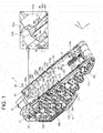
- FIG. 1 is an external appearance perspective view showing a core pack 1 of a battery pack.
- the core pack 1 is stored in an outer case (not shown in figures), and is used as a power source of an electric vehicle.
- FIG. 2 is an explored perspective view of the core pack 1.
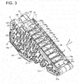
- FIG. 3 is an external appearance perspective view of a battery unit 10.
- the core pack 1 comprises the battery unit 10, and a circuit unit 20 which is set to the battery unit 10.
- the battery unit 10 has a cell assembly 30 in which plural battery cells 3 are disposed in a block shape (approximately triangular prism shape).
- plural cell groups 31A-31M are connected in series by plural lead plates 101-114 disposed at side surfaces (right and left triangular shape side surface portions) among its surfaces where positive terminals and negative terminals of the battery cells 3 are exposed.
- a circuit unit 20 comprises a protection circuit board 22, and a board holder 21which holds the protection circuit board 22.
- the circuit unit 20 has a flat board shape, and is set on a setting surface 11 (refer to FIG. 3 ) of the battery unit 10, and be assembled.
- This setting surface 11 is adjacent to outer surfaces of side board portions 120, 130 where the plural lead plates 101-114 are disposed, in surfaces of the cell assembly 30.
- the setting surface 11 is along X-Y plane, and the side board portions 120, 130 are along X-Z plane, and then the setting surface 11 is perpendicular to the side board portions 120, 130.
- the structure of the core pack 1 is compact.
- the circuit unit 20 includes a protection circuit into which an electric potential of the lead plate 101 of lowest electric potential, and electric potentials of the lead plates 102-113 corresponding to the number of the series-connected cell groups are inputted, and which protects the battery unit 10 based on inputted electric potentials
- an elongated direction of the setting surface 11 is a front - back direction (an arrow X is a back direction in the figures), and a short side direction of the setting surface 11 is a right and left direction (an arrow Y is a left direction in the figures), and a perpendicular direction to the setting surface 11 is an upper-lower direction (an arrow Z is a upper direction in the figures).
- a plurality (52 pieces) of the battery cells 3 which the battery unit 10 includes are arranged in parallel in a state that axes of the battery cells 3 of a cylindrical shape are along the right and left direction, and are stacked in a block shape (approximately triangular prism shape).
- Each of the battery cells 3 is a cylindrical shaped secondary battery, and has the positive terminal and the negative terminal at right and left end portions thereof.
- a lithium ion battery is used as the battery cell 3.
- the cell assembly 30 in which the plural battery cell 3 are disposed, are press-fitted into a pair of a battery holder members 12, 13 from right and left sides, and its disposed state is held.
- the battery holder members 12, 13 are made of resin, and are molded.
- the battery holder member 12 comprises the side board portion 120 of a triangular shape which covers the whole right surface of the cell assembly 30, and peripheral covering portions 121 which cover the right half peripheral surface in each of the battery cells 3. And the peripheral covering portions 121 project from the side board portion 120 toward left.
- the battery holder member 13 also comprises the side board portion 130 of a triangular shape which covers the whole left surface of the cell assembly 30, and peripheral covering portions 131 which cover the left half peripheral surface in each of the battery cells 3. And the peripheral covering portions 131 project from the side board portion 130 toward right.
- the battery holder member 12 and the battery holder member 13 are coupled each other in a state that the tip portions of the peripheral covering portions 121 and the peripheral covering portions 131 are contacted each other, and stably hold each of the battery cells 3 of the cell assembly 3.
- the lead plates 101-114 are disposed at the right and left side surfaces of the cell assembly 30, namely, separately on the outer surface of the side board portion 120 and on the outer surface of the side board portion 130.
- the setting surface 11 on which the circuit unit 20 is set is a plane (X-Y plane) perpendicular to the outer surface of the side board portion 120 and the outer surface of the side board portion 130, and has a rectangular shape similar to the circuit unit 20.
- each side which extends in the front - back direction (X direction) at both right and left sides of the setting surface 11, is adjacent to the top edges of the side board portion 120 and the side board portion 130.
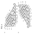
- FIG. 4 is a figure which shows and explains connecting state of the battery cells 3 included in the cell assembly 30, and (a) is a view seen from the right side surface, and (b) is a view from the left side surface.
- the cell groups 31A, 31B, 31C ... 31 M are shown in a solid line, and the lead plates 101-114 are shown in a dashed line.
- the plural battery cells 3 included in the cell assembly are divided into the first group in which the positive terminals face right and the second group in which the negative terminals face right. And the battery cells 3 belonging to the first group are divided into N pieces of the cell groups, and the battery cells 3 belonging to the second group are divided into (N+1) pieces of the cell groups.
- the positive terminals of the battery cells 3 face right, the negative terminals face left.
- the positive terminals of the battery cells 3 face left, the negative terminals face right.
- the lead plates 101, 103, 105, 107, 109, 111, 113 are arranged on the right side surface of the cell assembly 30 (the outer surface of the side board portion 120).
- the lead plates 102, 104, 106, 108, 110, 112, 114 are arranged on the left side surface of the cell assembly 30 (the outer surface of the side board portion 130).
- the negative terminals in the cell group 31A of the minimum electric potential are connected by the lead plate 101.
- the positive terminals of the 6 pieces of the cell groups 31B, 31 D, 31F, 31H, 31J, 31L belonging to the first group, and the negative terminals of the 6 pieces of the cell groups 31C, 31 E, 31G, 31I, 31K, 31 M belonging to the second group are connected through one common piece of the lead plate 103, 105, 107, 109, 111, 113 by each of the cell groups.
- the positive terminals in the cell group 31 M of the maximum electric potential are connected by the lead plate 102.
- the negative terminals of the 6 pieces of the cell groups 31 B, 31 D, 31 F, 31 H, 31J, 31 L belonging to the first group, and the negative terminals of the 6 pieces of the cell groups31A, 31C, 31 E, 31G, 31I, 31K belonging to the second group are connected through one common piece of the lead plate 102, 104, 106, 108, 110, 112 by each of the cell groups.
- the side board portion 120 and the side board portion 130 have window portions at the location where the terminals of the battery cells 3 face, and through each of the window portions, the lead plates 101-114 are weld-fixed to the terminals of the battery cells 3.
- the cell groups 31A, 31B, 31C ... 31M in which 4 pieces of the battery cells 3 are connected in parallel in each of the cell groups, are connected in 13 series (4 parallel 13 series).
- a tap portion 101a is provided at the top portion of the lead plate 101 of the minimum electric potential which is located at the right front end of the battery unit 10, and a tap portion 114a is provided at the top portion of the lead plate 114 of the maximum electric potential which is located at the left back end of the battery unit 10.
- Charging and discharging of the battery unit 10 is carried out through the tap portion 101 a and the tap portion 114a.
- tap portions 102a-113a which output the intermediate electric potential, are provided at the top portions of the lead plates 102-113.
- the tap portion 101 a and the tap portions 103a, 105a, 107a, 109a, 111a, 113a are arranged at the right side of the setting surface 11, namely along the boundary between the right surface of the cell assembly 30 and the setting surface 11 in the X direction, and the tap portions 102a, 104a, 106a, 108a, 110a, 112a and the tap portion 114a are arranged at the left side of the setting surface 11, namely along the boundary between the left surface of the cell assembly 30 and the setting surface 11 in the X direction.
- the tap portions arranged at the right side and the tap portions arranged at the left side are alternately arranged in the order of the tap portions 101a, 102a, 103a, 104a ... 113a, 114a from the front.
- the tap portions 102a-113a project upward beyond the setting surface 11.
- heights of the tap portions 102a-113a projecting from the setting surface 11, are set in such a way as decreasing from front to back (refer to FIG. 10(a) ).
- the side board portion 120 of the battery holder member 12 extends upward beyond the setting surface 11 at locations without the tap portions 103a, 105a, 107a, 109a, 111a, 113a, and extended portions 71-76 are formed.
- the tap portion 105a, 107a, 109a, 111 a, 113a are positioned between the adjacent extended portions 71-76.
- the side board portion 130 of the battery holder member 13 extends upward beyond the setting surface 11 at locations without the tap portions 102a, 104a, 106a, 108a, 110a, 112a, and extended portions 81-87 are formed.
- the tap portion 104a-112a are positioned between the adjacent extended portions 81-87.
- the circuit unit 20 is press-fitted between the extended portions 71-76 arranged at the right side of the setting surface 11 and the extended portions 81-87 at the left side of the setting surface 11, and is set on the setting surface 11 (refer to FIG. 8 ).
- the tap portions 101 a-114a are arranged along both right and left sides.
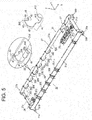
- FIG. 5 is a perspective view showing a structure of the circuit unit 20.
- the circuit unit 20 has the structure where the protection circuit board 22 is stored in the board holder 21 of a dish shape.
- the protection circuit board 22 has an elongated rectangular shape in the front - back direction (X direction).
- the board holder 21 includes a bottom board portion of an elongated rectangular shape on which the protection circuit board 22 is mounted, and a right side wall portion 21a, a left side wall portion 21b, a front side wall portion 21c, and a back side wall portion 21d surrounding the periphery of the protection circuit board 22.
- the board holder 21 is made of resin and molded.
- a terminal portion 26 of low electric potential side (negative side) is provided at the right front end portion, and a terminal portion 26 of low electric potential side (negative side) is provided at the right front end portion, and a terminal portion 27 of high electric potential side (positive side) is provided at the left back end portion.
- a connector 25 for power is provided at the back end portion of the protection circuit board 22.
- the terminal portions 26, 27 are connected to the connector 25 through a wiring 28 for power.
- the connector 25 is exposed outward from an opening window of the outer case.
- the protection circuit board 22 has various electronic parts which constitute the protection circuit, for example, a protection IC 23, switching elements 24a, 24b, or the like.
- FIG. 1 and 5 the electric parts of the circuit unit 20 are not shown in the figures. But, in FIG. 6 , wirings in the battery unit 10 and the circuit unit 20, the protection IC 23, the switching elements 24a, 24b, or the like are shown.
- the intermediate electric potentials at the lead plates 101-114 of the battery unit 10 are inputted into the protection IC 23.
- terminal portions 252-263 along the extended sides 22a, 22b in the front - back direction of the protection circuit board 22 are arranged corresponding to the tap portions 102a-113a of the battery unit 10.
- the intermediate electric potentials of the terminal portions 252-263 as input terminals are inputted into the protection IC 23.
- the terminal portion 26 for power and the terminal portions for the intermediate electric potential 253, 255, 257, 259, 261, 263 are arranged in order from the front
- the terminal portions for the intermediate electric potential 252, 254 256 258, 260, 262 and the terminal portion 27 for power are arranged in order from the front
- the terminal portions for the intermediate electric potential 252-263 are connected lead pins 202-213, and the intermediate electric potentials from the battery unit 10 are inputted into the protection IC 23 through the lead pins 201-212. Further, also the terminal portions 26, 27are connected to the tap portions 101a, 114a, and these electric potentials are inputted.
- the protection IC 23 checks the voltages in each of the cell group 31A-31M, based on each of inputted electric potentials at the time of charging and discharging, and controls currents of charging and discharging. For example, when the voltage of any one of the cell groups exceeds the upper limit, the switching element 24a is turned off, and charging current is stopped. Further, when the voltage of any one of the cell groups decreases less than the lower limit, the switching element 24b is turned off, and discharging current is stopped.
- holes are opened at each of the terminal portions for the intermediate electric potential 252-263, and one part in each of the lead pin 201-213 is press-fitted into the hole, and is soldered.
- a resin is potted in the board holder 21, and the lower portion in each of the lead pin 201-213 can be buried in the resin.
- the potting resin for example, a silicon resin material, an epoxy resin material, a urethane resin material, or the like can be used.
- the protection circuit board 22 is covered with a potting resin to configure the circuit unit, and the board holder 21 can be omitted in the circuit unit.
- the first bent portion 101b is bent toward left, and extended along the upper surface of the battery holder member 12.
- the second bent portion 101c is bent from the first bent portion 101b upward, and extended along the outer surface of a front side wall portion 21c.
- the connecting portion 101d is bent from the second bent portion 101 c backward.
- the connecting portion 101 d is extended so as to straddle the front side wall portion 21 c, and overlaps the terminal portion 26 of the circuit board 22, and then the connecting portion 101d contacts the terminal portion 26. By this, the lead plate 101 and the terminal portion 26 are electrically connected.
- the connecting portion 101 d has a cutout 101 e at the back end portion thereof, and at the front end portion of the board holder 21, an engaging pin 29 which is engaged with the cutout 101e projects upward adjacently to the terminal portion 26.
- the engaging pin 29 has a T-shape, when the engaging pin 29 is inserted into the cutout 101e, as the connecting portion 101d is pressed on the terminal portion 26 by the engaging pin 29, the connection between the connecting portion 101d and the terminal portion 26 is stably maintained.
- the terminal portion 27 is provided at a location corresponding to the tip portion of the tap portion 114a. This terminal portion 27 is connected to the connector 25 on the protection circuit board 22, and is connected also to the protection IC 23.
- the tap portion (power terminal portion) 114a overlaps and contacts the terminal portion, and the lead plate 114 and the terminal portion 27 are electrically connected.
- the lead pins 202-213 which connect the tap portions 102a-113a of the battery unit 10 and the terminal portions of the circuit unit 20, are explained.
- the lead pins 202-213 are extended from each of the terminal portions 252-263 provided in the protection circuit board 22 outside the board holder 21, and are extended toward each of the corresponding tap portions 102a-113a.
- the lead pins 203, 205, 207, 209, 211, 213 are disposed so as to straddle the right side wall portion 21a, and the lead pins 202, 204, 206, 208, 212 are disposed so as to straddle the left side wall portion 21b.
- Each of the lead pins 202-213 is made of a resilient metal wire, and the metal wire is bent.
- Shapes and fixings of the lead pins 202-213 are explained.
- the lead pin 206 is explained.
- the lead pin 206 comprises a fixing connection portion 41 which is fixed on the surface of the protection circuit board 22, an upward extending portion 42 which is bent from the fixing connection portion 41 and extends upward (Z direction) along the inner surface of the left side wall portion 21b, an outward extending portion 43 which is bent from the top portion of the upward extending portion 42 and extends outward (Y direction) beyond the left side wall portion 21b, a downward extending portion 44 which is bent from the outward extending portion 43 and extends downward, and a contacting portion 45 which is bent from the low end portion of the downward extending portion 44 to outward (Y direction) and contacts the lead plate 106.
- the contacting portion 45 is press-fitted into, and is electrically connected to a notch portion which is formed at the tap portion 106a of the lead plate 106.
- the tip portion 46 of the contacting portion 45 is bent downward.
- a curved portion 411 is formed so as to project downward.
- the curved portion 411 is press-fitted into a hole at the terminal portion 256 provided in the protection circuit board 22, and is connected to the terminal portion 256, and the fixing connection portion 41 is fixed at a predetermined position.
- the curved portion 411 and the terminal portion 256 are electrically connected and coupled by solder.
- a tip portion 412 of the fixing connection portion 41 is inserted into between the protection circuit board 22 and the left side wall portion 21 b. By this, fixing of the fixing connection portion 41 to the protection circuit board 22 is strengthened.
- the outward extending portion 43 is press-fitted into a cutout which is provided at the upper edge of the left side wall portion 21 b across the left side wall portion 21 b.
- the cutout 63 the outward extending portion 43 of the lead pin 206 is positioned in the front - back direction when the outward extending portion 43 is set to the board holder 21.
- a first rib portion 61 projects at the outer surface of the left side wall portion 21b. As described below in detail, this first rib portion 61 guides or fixes the location of the downward extending portion 44 of the lead pin 206.
- the front end side portion of the circuit unit 20 and the front end side portion of the battery unit 10 are pivotally coupled by an axis 50 (refer to FIG. 1 ) along the lateral direction, such that each of the lead pins 202-213 is connected to the corresponding tap portions 102a-113a in order while setting the circuit unit 20 on the setting surface 11 by pivoting or rotating the circuit unit 20.
- a pivot portion 51a which projects toward right, and a pivot portion 51b which project toward left, are provided at the lower side of the front end portion in the board holder 21, a pivot portion 51a which projects toward right, and a pivot portion 51b which project toward left, are provided.
- bearing portions 52, 53 are provided at the front end portions of the side board portions 120, 130 in the battery holder member2 12, 13, bearing portions 52, 53 are provided such that the pivot portions 51 a, 51 b is pivotally coupled thereto.
- the pivot portions 51 a, 51 b can be made of the same resin as the board holder 21, or made of metal or the like as a separate part.
- the bearing portions 52, 53 can be made of resin, or made of metal or the like as a separate part.
- FIG. 7(a), (b) are enlarged views of the bearing portion 52 provided at the front end portion of the side board portion 120 in the battery holder member 12.
- FIG. 7(a) is the partial enlarged view of the bearing portion 52 from the same direction as FIG. 3
- FIG. 7(b) is the partial view of the bearing portion 52 from the inner surface side.
- FIG. 7(c), (d) are enlarged views of the bearing portion 53 from the inner surface side provided at the front end portion of the side board portion 130 in the battery holder member 13.
- a bearing groove 530 which the pivot 51b is press-fitted into, is provided in the inner surface side of the bearing portion 53.
- the bearing groove 530 has an inner peripheral surface of a U-shape from the axle direction (Y direction).
- the bottom portion 532 of the bearing groove 530 is in an arc shape, and an opening portion 531 having an inner peripheral surface of a U-shape is provided at the diagonally upper rear of the bearing groove 530.
- the pivot portion 51 b of the circuit unit 20 is inserted from this opening portion 531 in the direction indicated in the arrow B defined by outline in FIG. 7(c), (d) , and the pivot portion 51 b is inserted until the bottom portion 532 of the bearing groove 530.
- projection portions 533 which prevent the pivot portion 51 b inserted from the come-off from the bottom portion 532 on the inner peripheral surface of the bearing groove 530, are provided.
- the bearing groove 520 is also the same structure as the bearing groove 530, and as shown in FIG. 7(b) , the bearing groove 520 has an inner peripheral surface of a U-shape from the axle direction (Y direction), and the bottom portion 522 of the bearing groove 530 is in an arc shape.
- An opening portion 521 having an inner peripheral surface of a U-shape is provided at the rear of the bearing groove 520.
- the pivot portion 51 a of the circuit unit 20 is inserted from this opening portion 531 in the direction indicated in the arrow A defined by outline in FIG. 7(a), (b) , and the pivot portion 51a is inserted until the bottom portion 522 of the bearing groove 520.
- FIG. 8 is a perspective view showing a state that the circuit unit 20 is pivotally coupled to the battery unit 10.
- the connecting portion 101d of the battery unit 10 is lifted as indicated by the arrow, and the front end portion of the circuit unit 20 is inserted under the connecting portion 101d, and the pivot portions 51a, 51b are inserted into the pivot grooves 520, 530 from the diagonally upper rear of the bearing portions 52, 53.
- pivot portions 51a, 51b When the pivot portions 51a, 51b are inserted until the bottom portions 522, 532 of the bearing groove 520, 530, the pivot portions 51a, 51b can be smoothly rotated at the bottom portions 522, 532 of the bearing portions 52, 53.
- the front end portion of the circuit unit 20 is pivotally coupled to the front end portion of the battery unit 10, and the circuit unit 20 can be rotated at the center of the axis 50.
- the core pack 1 has such a pivotable structure, as described below, at the time of manufacturing the core pack 1, while the circuit unit 20 is set on the setting surface 11 of the battery unit 10 by rotating the circuit unit 20, the lead pins 202-213 can be connected to the tap portions 101a-103a in this order.
- a method for manufacturing comprises a step of manufacturing the battery unit 10, a step of manufacturing the circuit unit 20 with lead pins, a step of setting the circuit unit 20 to the battery unit 10 and connecting the lead pins.
- the cell assembly 30 is assembled. And the lead plate 101-114 are set to the battery holder members 12, 13, and by welding them to the terminal in each of the battery cells 3, the battery unit 20 is manufactured.
- the protection circuit board 22 is stored in the board holder 21. Further, the lead pins 201-213 are press-fitted into and connected by soldering to the corresponding holes of the protection circuit board 22. In addition, a resin can be potted in the board holder 21.
- the circuit unit 20 with the lead pin 201-213 is pivotally coupled to the battery unit 10, and is set by rotating toward the setting surface 11. Accordingly, the lead pins 201-213 are connected to the tap portions 102a-113a.
- FIG. 9(a)-(d) are views showing the step of setting the circuit unit 20 to the battery unit 10.
- the pivot portions 51a, 51 b provided at the front end of the circuit unit 20 are press-fitted in the bearing portions 52, 53, and then pivotally coupled.
- the connecting portion 101d and the terminal portion 26 are contacted, and the tap portion 101 a and the terminal portion 26 are connected, and then the connection of the lower electrical potential side (negative side) in power line is made.
- the circuit unit 20 is set by rotating the circuit unit 20 toward the setting surface 11.
- setting of the circuit unit 2 on the setting surface 11 is carried out in a state that the tip portion of the tap portion 114a is raised as shown in the arrow of the FIG. 8 .
- the distances from the axis 50 to the lead pins 202-213 become bigger in this order.
- the lead pins 202-213 are press-fitted into the taps with the contacting portions 45 contacting the tap portion 102a-113a.
- the lead pins are connected to the tap portions in order from the closest one to the axis 50.
- the lead pin 203, 205, 207, 209, 213 arranged along the right side wall portion 21a of the circuit unit 20, are press-fitted into and connected to the taps of the tap portions 103a, 105a, 107a, 109a, 111a, 113a along a path C3, C5, C7, C9, C11, C13 of an arc shape according to the rotation of the circuit unit 20.
- the lead pin 202, 204, 206, 208, 210, 212 arranged along the right side wall portion 21 b of the circuit unit 20, are press-fitted into and connected to the taps of the tap portions 102a, 104a, 106a, 108a, 110a, 112a along a path of an arc shape.
- the rotated angle of the lead pins 202-213 is common, but in the order in which the lead pins 202-213 contact the tap portions 102a-113a, first the lead pin 202 closest to the axis 50 contacts the tap portion 102a, and the lead pins 203, 204 ... contact the tap portions 103a, 104a, 105a .. in order, and at last the lead pin 213 contacts the tap portion 113a.
- FIG. 10(b) This figure compares the rotated angle in the lead pin 203 close to the axis 50, and the lead pin 213 distant from the axis 50.
- the angle of the circuit unit 20 to the setting surface 11 is theta ( ⁇ ) 0. Therefore, when the circuit unit 20 is rotated by the angle ⁇ 0 from this state, the circuit unit 20 is set on the setting surface 11. According to this, the lead pin 203 and the lead pin 213 are also rotated by the common angle ⁇ 0, and the connection of the tap portion 103a and the tap portion 113a are completed.
- the lead pins contact the tap portion 102a-113a in the order from the pin close to the axis 50 to the pin distant from the axis 50.
- the tap portions 102a-113a project from the setting surface 11 upward as described above, and heights of projecting from the setting surface 11 among the tap portions 102a-113a are set lower as the tap portions become distant from the axis 50.
- the tip portion of the tap portions 114a is bent on the terminal portion 27, and then the lead plate 114 as the terminal for power of the high electrical side and the terminal portion 27 are electrically connected.
- the circuit unit 20 is fixed to the battery unit 10 by screw at the front end portion and the back end portion thereof, in a state that the circuit unit 20 is set on the setting surface 11.
- a through hole 54a is opened at the location of the axis 50 in the bearing portion 52
- a through hole 54b is opened at the location of the axis 50 in the bearing portion 53.
- screws (not shown in the figures) are screwed into screw holes 510 (refer to FIG. 5 ) of the pivot portions 51 a, 51 b through these through holes 54a, 54b, and thus the pivot portions 51a, 51b are fixed to the bearing portions 52, 53.
- pivot portions 56a, 56b are provided at the back end portion of the board holder 21, and on the other hand, in the side board portion 120 of the battery holder member 12 and the side board portion 130 of the battery holder member 13, through holes 57a, 57b are opened at the locations corresponding to the pivot portions 56a, 56b in the state that the circuit unit 20 is set on the setting surface 11. Further, screws (not shown in the figures) are screwed into screw holes 560 (refer to FIG. 5 ) of the pivot portions 56a, 56b through these through holes 57a, 57b, and thus the pivot portions 56a, 56b are fixed to the side board portions 120, 130.
- the curved portion in each of the lead pins 202-213 is press-fitted into the hole of the terminal portions 252-263, and is fixed at the predetermined portion of the protection circuit board 22, and the outward extending portion 43 in each of the lead pins 202-213 is press-fitted into the cutout 63, and is fixed at the predetermined portion of the board holder 21.
- the downward extending portion 44 and the contacting portion 45 in each of the lead pins 202-213 are not fixed to the board holder 21.
- the outward extending portion 43, the downward extending portion 44, and the contacting portion 45 are resilient, those are resiliently deformed by adding external force. Therefore, the contacting portion 45 is able to move to some extent in the front-back direction by adding external force.
- a pair of the first rib 61 and a second rib 62 are provided so as to surround the downward extending portion 44 in each of the lead pins 202-213, and then the downward extending portion 44 and the contacting portion 45 are limited in the movable extent.
- FIG. 12(a) is an enlarged plan view in case that the vicinity of the lead pins 203, 205 in the circuit unit 20 is seen from above.
- FIGs. 12(b), (c) are sectional views in case that the vicinity of the lead pin 203 is seen from back.
- the first ribs 61 are provided at the location adjacent to the cutouts 63.
- the first rib 61 comprises an outward projecting portion 61 a which projects from the outer surface of the right side wall portion 21a to outward (the right direction, the opposite direction to Y direction, and the bent portion 61b which is bent from the outward projecting portion 61 a to front (the opposite direction to the X direction).
- the first rib 61 has an L-shape.
- the outward projecting portion 61 a extends along the outward extending portion 43 of the lead pin 203, the bent portion 61b covers the outer side of the downward extending portion 44.
- the downward extending portion 44 in each of the lead pins 202-213 is surrounded the first rib 61 and the second rib 62, even though the downward extending portion 44 is resiliently deformed, the downward extending portion 44 stays within the extent surrounded by the first rib 61 and the second rib 62, and the contacting portion 45 is limited in the extent in which the contacting portion 45 can move in the front-back direction.
- the contacting portion 45 in each of the lead pins crosses the tap portions 102a-113a, and is press-fitted into the notch portion in each of the tap portion 102a-113a, and is guided at the location in the right and left direction as described below.
- the first rib 61 and the second rib 62 which surround the downward extending portion 44 of the lead pin 203 are press-fitted between the bearing portion 52 and the extended portion 71 inside the tap portion 103a, and the contacting portion 45 of the lead pin 203 contacts the tap portion 103a.
- the first rib 61 and the second rib 62 which surround the downward extending portion 44 of the lead pin 205 are press-fitted between the extended portion 71 and the extended portion 72 inside the tap portion 103a, and the contacting portion 45 of the lead pin 205 contacts the tap portion 105a.
- first rib 61 and the second rib 62 which surround the downward extending portion 44 in each of the other lead pins 202, 204, 206-213, are press-fitted between the adjacent extended portions inside the tap portions 102a, 104a, 106a-113a, and then the contacting portions 45 of the lead pins 202, 204, 206-213 contact the tap portion 102a, 104a, 106a-113a.
- first rib 61 and the second rib 62 are inclined.
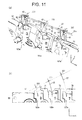
- FIG. 11 (a) , FIG. 12(b), FIG. 12(c) the first rib 61 and the second rib 62 corresponding to the lead pin 203 are shown.
- the lower end surface 610 of the first rib 61 is not perpendicular to the right side wall portion 21a, and is inclined in the right and left direction.
- the lower end surface 620 of the rib 62 is inclined in the right and left direction
- the contacting portions 45 of the corresponding lead pins are surely press-fitted into, and properly contact the notch portions of the tap portions.
- the first rib 61 and the second rib 62 is smoothly inserted inside the tap portion 103a (into the left side of the tap portion 103a), with the inclined lower end surfaces 610, 620 sliding on the upper end portion of the tap portions.
- FIGs. 12(a) to (c) since the contacting portion 45 of the lead pin 203 projects in the right direction (the opposite direction to Y direction) through under the bent portion 61 b in the first rib 61, the contacting portion 45 of the lead pin 203 is surely press-fitted into the notch portion of the tap portion 103a, and is positioned in the right and left direction.
- the contacting portion 45 in each of the lead pins 202-213 is surely press-fitted into, and is connected to the notch portion of the corresponding tap portions 102a-113a by the function of the first rib 61 and the second rib 62
- the notch portions formed at the tap portions 102a-113a are formed in such a way as inclining in the direction that the notch portions are narrowed as going from the setting surface 11 side to the battery cells 3 side. Namely, a shape in each of the notch portions is formed such that the width is gradually becoming narrower as going from its inlet to the inner portion along the path of the arc shape drawn by the corresponding lead pins 202-213.
- the contacting portion 45 in each of the lead pins 202-213 contacts the corresponding tap portions 102a-113a, and after that, is guided into the notch, and then is smoothly inserted into the inner portion of the notch portion.
- FIG. 11 (a) is a perspective view showing a state that the lead pins 203, 205, 207 contact the tap portions, (b) is its explanation drawing.
- the lead pins 203, 205, 207 are explained below, referring to those figures.
- the contacting portions 45 of the lead pin 203, 205, 207 are connected to the tap portions 103a, 105a, 107a along the path C3, C5, C7 of the arc shape.
- the notch portion (slit) S3, S5, S7 into which the corresponding lead pin 203, 205, 207 is press-fitted, is formed, and the notch portion S3, S5, S7 is formed along the above path C3, C5, C7.
- the notch portions S3, S5, S7 are formed such that the width is gradually becoming narrower as going from its inlet to the inner portion with the width of the inlet wide.
- the contacting portion 45 in each of the lead pins is enable to move to some extent in the front-back direction by adding external force, even though the paths in which the contacting portions 45 of the lead pins 203, 205, 207 are inserted into the notch portions S3, S5, S7, are slipped a little in the front-back direction, while the contacting portions 45 of the lead pins 203, 205, 207slide on the edges of the notch portions S3, S5, S7, those can be smoothly inserted into the inner portions from the inlets of the notch portions.
- the tap portions of the battery unit and each of the input terminals are connected.
- the tap portion of which the electrical potential is largely different from the other tap portion already connected is connected, the series-connected voltage of the cell assembly between them is applied to the IC of the circuit unit, and it happens that higher voltage more than the rated voltage is applied to the protection IC, and it happens that the protection IC is broken. And there is a possibility that the trouble of the IC has a bad influence on the other elements mounted on the circuit board.
- the tap portion 101 a and the terminal portion 26 of the minimum electrical potential are connected, and next while the circuit unit 20 is rotated, and is set on the setting surface 11, the tap portions 102a-103a of the battery unit 10 are automatically connected to the terminal portions 252-263 in the ascending order from low electrical potential side.
- the lead pins 202-213 are automatically separated from the tap portions 102a-113a in the order from high electrical potential. Accordingly, by the same reason as assembling, it prevents higher voltage more than the rated voltage from being applied to the protection IC.
- the circuit unit 20 of the core pack 1 can be easily disconnected from the battery unit 10.
- the number of the series-connected cell groups is 13, but it is acceptable that this series-connected number is equal to or more than 3.
- the number of the series-connected cell groups is an uneven number, and the tap portion of the maximum electrical potential and the tap portion of the minimum electrical potential are disposed at the left side surface and the right side surface. But it is acceptable that the series-connected number is an even number, and in this case, the tap portion of the maximum electrical potential and the tap portion of the minimum electrical potential are disposed at the same side surface.
- holes are opened at the front end portions of the circuit holder and the battery holder, and a shaft member is inserted into the holes, and then the circuit unit can be pivotally coupled to the battery unit.
- the positive terminals and the negative terminals are exposed at the one edge surface, and the plural lead plates are disposed at its edge surface, and the plural tap portions are arranged in the order of the electrical potentials at the one side of the setting surface in the battery unit.
- the plural lead pins are provided at the one side of the circuit unit, and each the tap portions can be connected according to rotating the circuit unit.
- the battery pack of the present invention is used for a power source of an electric bicycle, an electric vehicle, a working robot, or the like.
Landscapes
- Chemical Kinetics & Catalysis (AREA)
- Electrochemistry (AREA)
- General Chemical & Material Sciences (AREA)
- Chemical & Material Sciences (AREA)
- Engineering & Computer Science (AREA)
- Manufacturing & Machinery (AREA)
- Microelectronics & Electronic Packaging (AREA)
- Life Sciences & Earth Sciences (AREA)
- Power Engineering (AREA)
- Transportation (AREA)
- Mechanical Engineering (AREA)
- Sustainable Energy (AREA)
- Sustainable Development (AREA)
- Battery Mounting, Suspending (AREA)
- Secondary Cells (AREA)
- Connection Of Batteries Or Terminals (AREA)
Abstract
Description
- The present invention is related to a battery pack and a method for manufacturing the same, especially, the battery pack which comprises a battery unit in which plural cell groups are connected in series, and a protection circuit board.
- As a battery pack for an electric bicycle, an electric vehicle, a working robot, or the like, the battery pack shown in
patent literature 1 has been developed. This battery pack comprises a battery unit in which plural battery cells are connected, a protection circuit board including a protection circuit, and those are stored in a case made of resin or the like. - In this type of the battery pack, the battery unit has a battery holder which holds the plural battery cells in a shape of block, and plural cell groups are connected in series by lead plates, and then the output of a high voltage is obtained. This type of the battery pack is often used.
- Further, the battery pack shown in
patent literature 1 has a circuit unit which stores a circuit board including an IC for a protection circuit within a board holder. And the circuit unit is disposed on the surface of the battery unit, and is fixed to the battery holder. - By the way, in the battery pack in which the cell groups are connected in series, at the time of charging and discharging, the protection circuit board checks not only the voltage between both ends of the series-connected cell groups but also intermediate electric potentials, and controls so as to prevent each of the battery from over charge or over discharge based on it.
- In order that the intermediate electric potentials are inputted into the protection circuit board, in the battery pack shown in patent literature1, each of input terminals of the IC on the protection circuit board are connected to lead plates between the cell groups through lead wires between the protection circuit board and the battery unit.
-
- Patent Literature 1: Japanese Laid-Open Patent Publication No.
2010-277795 - Patent Literature 2: Japanese Laid-Open Patent Publication No.
2011-243426 - When the battery pack in which the protection circuit board checks the intermediate electric potentials is manufactured, the battery unit and the protection circuit board are manufactured, and the input terminals and the lead plates showing the intermediate electric potentials in the battery unit are connected by the lead wire or the like.
- In a connecting step by this lead wire, for example, after one end portion of each of the lead wires is connected to the protection circuit board side, the protection circuit board is set to the battery unit, and the other end portion of each of the lead wires is connected to the corresponding tap portion of the lead plate in the battery unit by engaging each other.
- In the connecting step in which the tap portions of the battery unit are connected to the terminals of the protection circuit board by such plural lead wires, in order not to applying a high voltage to the IC of the protection circuit board, it is necessary that the lead wires are connected to the tap portions of the lead plates in the battery unit in electric potential order.
- Therefore, connecting step of the protection circuit board and the lead plates by the plural lead wires is done by manual procedures, and then its step is troublesome.
- The present disclosure is developed for the purpose of solving such drawbacks. One non-limiting and explanatory embodiment provides that in a battery pack having a battery unit in which plural cell groups are connected in series, and a protection circuit board to protect by detecting intermediate electric potentials, tap portions of lead plates in the battery unit and terminals of the protection circuit board are easily connected.
- The present disclosure has the following configuration.
- A battery pack of the present disclosure comprises a battery unit a battery unit having a cell assembly having plural battery cells, and plural lead plates being connected to positive terminals and negative terminals of the plural battery cells of the cell assembly, in which the battery cells in each of cell groups are connected in parallel through the plural lead plates and the cell groups are connected in series, and a protection circuit board being mounted on one surface of the cell assembly, and each of the lead plates extend toward the one surface as each of tap portions, and each of the tap portions is disposed such that electric potentials of the tap portions are arranged in increasing order or decreasing order in one direction, and the protection circuit board has plural input terminals arranged in the one direction corresponding to the tap portions, and a pivotable structure is provided at an end portion side in the one direction on a surface side where the protection circuit board is disposed, and each of the input terminals are connected to each of the tap portions corresponding thereto.
- A method for manufacturing a battery pack of the present disclosure comprises a step of manufacturing a battery unit which comprises a cell assembly which is constituted in a state that the positive terminals and the negative terminals of the plural battery cells are horizontally disposed, and plural lead plates being connected to positive terminals and negative terminal of the plural battery cells of the cell assembly, and in which the battery cells in cell groups are connected in parallel through the plural lead plates and the cell groups are connected in series, a step of manufacturing a protection circuit board being mounted on one surface of the cell assembly, and a step of setting the protection circuit board on the one surface of the cell assembly, and in the battery unit manufactured in the step of manufacturing the battery unit, each of the lead plates extended toward the one surface as each of tap portions, and each of the tap portions is disposed such that electric potentials of the tap portions are arranged in increasing order or decreasing order in one direction, and the protection circuit board manufactured in the step of manufacturing the protection circuit board, has plural input terminals arranged in the one direction corresponding to each of the tap portions, and the step of setting the protection circuit board further comprises a sub-step of pivotally coupling in which the protection circuit board and the battery unit are pivotally coupled at an end portion in the one direction as an axis in spaced relationship with each other, and a sub-step of rotating in which the protection circuit board is set by rotating the protection circuit board pivotally coupled, and in the sub-step of pivotally coupling, the input terminal closest to the axis is connected to the corresponding tap portion, and in the sub-step of rotating, the other input terminals are connected to the corresponding tap portions in the order of the electric potentials.
-
- [1] In a battery pack of the present disclosure, (a)each of the lead plates extend toward the one surface on which the protection circuit board is set as a tap portion, and the tap portions are disposed such that electric potentials of the tap portions are arranged in increasing order or decreasing order in one direction, (b)the protection circuit board has plural input terminals arranged in the one direction corresponding to the tap portions, (c)the battery unit and the protection circuit board are pivotally coupled by a pivotable structure at an end portion side in the one direction on a surface side where the protection circuit board is disposed, (d)the input terminals are connected to the tap portions corresponding thereto.
- Accordingly, when this battery pack is assembled, while the protection circuit board is rotated around the axis, and is set, each of the input terminals can contact the tap portion of the corresponding lead plate in the order from one close to the axis.
- Therefore, each of the input terminals in the protection circuit board can be easily connected to the corresponding lead plate in the order of the electrical potential.
- In the above battery pack, the following structures can be used.
- In the pivotable structure the battery unit and the protection circuit board are pivotally coupled by an axis perpendicular to the one direction along the one surface.
- The plural input terminals have lead pins, and the input terminals are electrically connected to the tap portions corresponding thereto through the lead pins.
- Here, the tap portions corresponding to the lead pins has notch portions in which the lead pins are inserted respectively.
- By this, according to setting the protection circuit board, each of the lead pins is press-fitted into the notch portion of the tap portion, connection between the lead pin and the tap portion is surely carried out.
- The notch portions provided at the tap portions are formed in such a way as inclining in the direction that the notch portions are narrowed as going from the one surface side to the battery cells side.
- Therefore, the lead pins are guided, and are inserted into the notch portions, and after the insertion, the lead pins are press-fitted into the notch portions, and connection can be surely carried out.
- The battery unit has a battery holder which holds the cell assembly, and the protection circuit board is set to a board holder to hold the protection circuit board, and a pivot portion is provided at the board holder and a bearing portion is provided at the battery holder such that the pivot portion is pivotally coupled thereto. Therefore, the above pivotally coupling can be easily carried out.
- Here, the board holder has rib portions which guide the lead pins into locations for contacting the tap portions corresponding to the lead pins respectively.
- The cell assembly is constituted in a state that the positive terminals and the negative terminals of the plural battery cells are horizontally disposed, and the plural lead plates are disposed at side surfaces where the positive terminals and the negative terminals are exposed, and the cell groups where the same number of the battery cells are connected in parallel are connected in series through the plural lead plates, and the one surface of the cell assembly is adjacent to the side surfaces, and the protection circuit board carries out protection of a battery circuit by inputting the electrical potential in each of the lead plates.
- The plural battery cells which constitute the cell assembly, comprises a first group in which the positive terminals are exposed at a first side surface of the side surfaces, and a second group in which the negative terminals are exposed at the first side surface, and the plural lead plates are disposed at the first side surface of the cell assembly and a second side surface facing the first side surface, and the one surface is adjacent to the first side surface and the second side surface between both side surfaces.
- In this case, the tap portions which extend from the plural lead plates and are provided, are arranged along both side edges of the one surface in the order of the electrical potential in the one direction, and also in the protection circuit board, the plural input terminals corresponding to the tap portion of the battery unit are arranged along both side surfaces in the one direction.
- Further, as the plural lead plates are disposed, being divided into both the first side surface and the facing second side surface, and the protection circuit board is set on the one surface between both side surfaces, the battery pack can be compact.
- Here, in the battery cells belonging to the first group, each of the cell group has the equal number of the battery cells, and the first group has N (N is an integer of 1 or more) pieces of the cell groups, and in the battery cells belonging to the second group, each of the cell group has an equal number of the battery cells, and the second group has N+1 pieces of the cell groups, and in the first side surface, the negative terminals of the cell group having a minimum electric potential of the second group, are connected to one piece of the lead plate, and the positive terminals in N pieces of the cell groups belonging to the first group and the negative terminals in N pieces of the cell groups belonging to the second group are connected through one common piece of the lead plate by each of the cell groups, and in the second side surface facing the first side surface, the positive terminals of the cell group having the maximum electric potential, are connected to one piece of the lead plate, and the positive terminals in N pieces of the cell groups belonging to the first group and the negative terminals in N pieces of the cell groups belonging to the second group are connected through one common piece of the lead plate by each of the cell groups.
- A method for manufacturing a battery pack of the present disclosure comprises a step of manufacturing a battery unit which comprises a cell assembly having plural battery cells, and plural lead plates being connected to positive terminals and negative terminal of the plural battery cells of the cell assembly, and in which the battery cells in cell groups are connected in parallel through the plural lead plates and the cell groups are connected in series, a step of manufacturing a protection circuit board being mounted on one surface of the cell assembly, and a step of setting the protection circuit board on the one surface of the cell assembly, and in the battery unit manufactured in the step of manufacturing the battery unit, each of the lead plates extended toward the one surface each of tap portions, and each of the tap portions is disposed such that electric potentials of the tap portions are arranged in increasing order or decreasing order in one direction, and the protection circuit board manufactured in the step of manufacturing the protection circuit board, has plural input terminals arranged in the one direction corresponding to each of the tap portions, and the step of setting the protection circuit board further comprises a sub-step of pivotally coupling in which the protection circuit board and the battery unit are pivotally coupled at an end portion in the one direction as an axis in spaced relationship with each other, and a sub-step of rotating in which the protection circuit board is set by rotating the protection circuit board pivotally coupled, and in the sub-step of pivotally coupling, the input terminal closest to the axis is connected to the corresponding tap portion, and in the sub-step of rotating, the other input terminals are connected to the corresponding tap portions in the order of the electric potentials.
- Therefore, in this method for manufacturing, in the step of setting, according to rotating the protection circuit board pivotally coupled, each of the input terminals of the protection circuit board can be connected to each of the corresponding tap portion in the order of the electrical potential.
- In the above method for manufacturing the battery pack, the followings can be used.
- In the step of manufacturing the protection circuit board, connecting members are provided at, and are extended from each of the input terminals except for the input terminal closest to the axis, and in the sub-step of rotating, the connecting member connected to each of the input terminals is connected to the corresponding tap portion in the order of the electric potentials.
- In the step of manufacturing the protection circuit board, the connecting members connected to the input terminals include lead pins, and the tap portions of the lead plates used in the step of manufacturing the battery unit have notches corresponding to the lead pins, and in the sub-step of rotating, according to rotating the protection circuit board, electrical connections are carried out by press-fitting the corresponding lead pins into the notch in each of the tap portions.
- By this, connections between the lead pins and the tap portion are surely carried out.
- In the step of manufacturing the protection circuit board, a board holder to hold the protection circuit board is set to the protection circuit board including electric parts, and a pivot portion is provided at the board holder, and in the step of manufacturing the battery unit, the battery unit is made by using a battery holder to hold the plural cell groups, and a bearing portion is provided at the battery holder.
- Accordingly, in the sub-step of pivotally coupling, the pivot portion is press-fitted into the bearing portion, and then is pivotally coupled.
- In the step of manufacturing the battery unit, an inner surface of the bearing portion formed at the battery holder is partially opened, and in the sub-step of pivotally coupling, the pivot portion is inserted into through an opening portion of the inner surface portion.
-
-
FIG. 1 is an external appearance perspective view showing acore pack 1 -
FIG. 2 is an explored perspective view showing a configuration of thecore pack 1. -
FIG. 3 is an external appearance perspective view of abattery unit 10 included in thecore pack 1. -
FIG. 4(a), (b) are figures which shows and explains connecting state ofbattery cells 3 included in acell assembly 30. -
FIG. 5 is a perspective view showing a structure of acircuit unit 20. -
FIG. 6 is a figure showing connecting portions in thebattery unit 10 and thecircuit 20. -
FIG. 7(a), (b) are enlarged views of a bearingportion 52, and (c), (d) are enlarged views of a bearingportion 53. -
FIG. 8 is a perspective view showing a step that thecircuit unit 20 is pivotally coupled to thebattery unit 10. -
FIG. 9(a)-(d) are views showing the step of setting thecircuit unit 20 to thebattery unit 10. -
FIG. 10(a) is a side view showing a state that lead pins are connected to tap portions in order according to setting thecircuit unit 20, and (b) is its explanation figure. -
FIG. 11 (a) is a perspective view showing a state that the lead pins contact the tap portion in order, and (b) is its explanation figure. -
FIG. 12(a) is an enlarged plan view in case that the vicinity of the lead pins 203, 205 in thecircuit unit 20 is seen from above, and (b), (c) are sectional views in case that the vicinity of thelead pin 203 is seen from back. - The following describes embodiments of the present invention based on the figures. However, embodiments in the following description are used as examples to easily understand the structure, operation, and results of the present invention, and the present invention is in no way limited to those embodiments.
-
FIG. 1 is an external appearance perspective view showing acore pack 1 of a battery pack. In this battery pack, thecore pack 1 is stored in an outer case (not shown in figures), and is used as a power source of an electric vehicle. -
FIG. 2 is an explored perspective view of thecore pack 1.FIG. 3 is an external appearance perspective view of abattery unit 10. - The
core pack 1 comprises thebattery unit 10, and acircuit unit 20 which is set to thebattery unit 10. - The
battery unit 10 has acell assembly 30 in whichplural battery cells 3 are disposed in a block shape (approximately triangular prism shape). In thiscell assembly 30,plural cell groups 31A-31M are connected in series by plural lead plates 101-114 disposed at side surfaces (right and left triangular shape side surface portions) among its surfaces where positive terminals and negative terminals of thebattery cells 3 are exposed. - A
circuit unit 20 comprises aprotection circuit board 22, and a board holder 21which holds theprotection circuit board 22. Thecircuit unit 20 has a flat board shape, and is set on a setting surface 11 (refer toFIG. 3 ) of thebattery unit 10, and be assembled. This settingsurface 11 is adjacent to outer surfaces ofside board portions cell assembly 30. The settingsurface 11 is along X-Y plane, and theside board portions surface 11 is perpendicular to theside board portions - In this way, as the
circuit unit 20 is set on the settingsurface 11 between both side surfaces where the lead plates 101-114 are disposed in thebattery unit 10, the structure of thecore pack 1 is compact. - The
circuit unit 20 includes a protection circuit into which an electric potential of thelead plate 101 of lowest electric potential, and electric potentials of the lead plates 102-113 corresponding to the number of the series-connected cell groups are inputted, and which protects thebattery unit 10 based on inputted electric potentials - In explanation, an elongated direction of the setting
surface 11 is a front - back direction (an arrow X is a back direction in the figures), and a short side direction of the settingsurface 11 is a right and left direction (an arrow Y is a left direction in the figures), and a perpendicular direction to the settingsurface 11 is an upper-lower direction (an arrow Z is a upper direction in the figures). - As shown in
FIG. 2 , a plurality (52 pieces) of thebattery cells 3 which thebattery unit 10 includes, are arranged in parallel in a state that axes of thebattery cells 3 of a cylindrical shape are along the right and left direction, and are stacked in a block shape (approximately triangular prism shape). - Each of the
battery cells 3 is a cylindrical shaped secondary battery, and has the positive terminal and the negative terminal at right and left end portions thereof. Here, a lithium ion battery is used as thebattery cell 3. - The
cell assembly 30 in which theplural battery cell 3 are disposed, are press-fitted into a pair of abattery holder members battery holder members - The
battery holder member 12 comprises theside board portion 120 of a triangular shape which covers the whole right surface of thecell assembly 30, and peripheral coveringportions 121 which cover the right half peripheral surface in each of thebattery cells 3. And theperipheral covering portions 121 project from theside board portion 120 toward left. - The
battery holder member 13 also comprises theside board portion 130 of a triangular shape which covers the whole left surface of thecell assembly 30, and peripheral coveringportions 131 which cover the left half peripheral surface in each of thebattery cells 3. And theperipheral covering portions 131 project from theside board portion 130 toward right. - The
battery holder member 12 and thebattery holder member 13 are coupled each other in a state that the tip portions of theperipheral covering portions 121 and theperipheral covering portions 131 are contacted each other, and stably hold each of thebattery cells 3 of thecell assembly 3. - The lead plates 101-114 are disposed at the right and left side surfaces of the
cell assembly 30, namely, separately on the outer surface of theside board portion 120 and on the outer surface of theside board portion 130. The settingsurface 11 on which thecircuit unit 20 is set, is a plane (X-Y plane) perpendicular to the outer surface of theside board portion 120 and the outer surface of theside board portion 130, and has a rectangular shape similar to thecircuit unit 20. And each side which extends in the front - back direction (X direction) at both right and left sides of the settingsurface 11, is adjacent to the top edges of theside board portion 120 and theside board portion 130. - In the setting
surface 11, parts of the peripheral surface of thebattery cells 3 arranged on the surface of thecell assembly 30, and parts of theperipheral covering portions circuit unit 20 is stably set on the settingsurface 11. -
FIG. 4 is a figure which shows and explains connecting state of thebattery cells 3 included in thecell assembly 30, and (a) is a view seen from the right side surface, and (b) is a view from the left side surface. In the figure, thecell groups - Here, a case that 4 pieces of the
battery cells 3 are connected in parallel and constitute the one cell group, is explained. - The
plural battery cells 3 included in the cell assembly, are divided into the first group in which the positive terminals face right and the second group in which the negative terminals face right. And thebattery cells 3 belonging to the first group are divided into N pieces of the cell groups, and thebattery cells 3 belonging to the second group are divided into (N+1) pieces of the cell groups. - As shown in
FIG. 4(a), (b) , the number of the battery cells which constitute thecell assembly 30 is 52, and thebattery cells 3 are divided into 13 pieces of the cell groups31A, 31B, 31C ... 31 M (N=6). - In the N pieces (6 pieces) of the
cell groups battery cells 3 face right, the negative terminals face left. - On the other hand, in the N+1 pieces (7 pieces) of the
cell groups battery cells 3 face left, the negative terminals face right. - As shown in
FIG. 2 ,FIG. 4, and FIG. 4(a) , among the lead plates 101-114, thelead plates lead plates - And at the right side surface of the
cell assembly 30, the negative terminals in thecell group 31A of the minimum electric potential are connected by thelead plate 101. In the remaining 12 pieces of thecell groups 31B-31M, the positive terminals of the 6 pieces of thecell groups cell groups lead plate FIG. 4(b) , at the left side surface of thecell assembly 30, the positive terminals in thecell group 31 M of the maximum electric potential are connected by thelead plate 102. In the remaining 12 pieces of thecell groups 31A-31L, the negative terminals of the 6 pieces of thecell groups lead plate - The
side board portion 120 and theside board portion 130 have window portions at the location where the terminals of thebattery cells 3 face, and through each of the window portions, the lead plates 101-114 are weld-fixed to the terminals of thebattery cells 3. - In this way, as the lead plates 101-114 are arranged separately at both right and left side surfaces of the
cell assembly 30, thecell groups battery cells 3 are connected in parallel in each of the cell groups, are connected in 13 series (4 parallel 13 series). - A
tap portion 101a is provided at the top portion of thelead plate 101 of the minimum electric potential which is located at the right front end of thebattery unit 10, and atap portion 114a is provided at the top portion of thelead plate 114 of the maximum electric potential which is located at the left back end of thebattery unit 10. - Charging and discharging of the
battery unit 10 is carried out through thetap portion 101 a and thetap portion 114a. - Further,
tap portions 102a-113a which output the intermediate electric potential, are provided at the top portions of the lead plates 102-113. Thetap portion 101 a and thetap portions surface 11, namely along the boundary between the right surface of thecell assembly 30 and the settingsurface 11 in the X direction, and thetap portions tap portion 114a are arranged at the left side of the settingsurface 11, namely along the boundary between the left surface of thecell assembly 30 and the settingsurface 11 in the X direction. - In the overall arrangement order of these
tap portions 101a-114a in the front - back direction, as shown inFIG. 3 , the tap portions arranged at the right side and the tap portions arranged at the left side are alternately arranged in the order of thetap portions - The
tap portions 102a-113a project upward beyond the settingsurface 11. Here, heights of thetap portions 102a-113a projecting from the settingsurface 11, are set in such a way as decreasing from front to back (refer toFIG. 10(a) ). - The
side board portion 120 of thebattery holder member 12 extends upward beyond the settingsurface 11 at locations without thetap portions tap portion - In the same way, the
side board portion 130 of thebattery holder member 13 extends upward beyond the settingsurface 11 at locations without thetap portions tap portion 104a-112a are positioned between the adjacent extended portions 81-87. - The
circuit unit 20 is press-fitted between the extended portions 71-76 arranged at the right side of the settingsurface 11 and the extended portions 81-87 at the left side of the settingsurface 11, and is set on the setting surface 11 (refer toFIG. 8 ). - And when the
circuit unit 20 is set on the settingsurface 11, thetap portions 101 a-114a are arranged along both right and left sides. -
FIG. 5 is a perspective view showing a structure of thecircuit unit 20. - The
circuit unit 20 has the structure where theprotection circuit board 22 is stored in theboard holder 21 of a dish shape. Theprotection circuit board 22 has an elongated rectangular shape in the front - back direction (X direction). Theboard holder 21 includes a bottom board portion of an elongated rectangular shape on which theprotection circuit board 22 is mounted, and a rightside wall portion 21a, a leftside wall portion 21b, a frontside wall portion 21c, and a backside wall portion 21d surrounding the periphery of theprotection circuit board 22. Theboard holder 21 is made of resin and molded. - As shown in
FIG. 1 andFIG. 2 , in theprotection circuit board 22, as a terminal for power, aterminal portion 26 of low electric potential side (negative side) is provided at the right front end portion, and aterminal portion 26 of low electric potential side (negative side) is provided at the right front end portion, and aterminal portion 27 of high electric potential side (positive side) is provided at the left back end portion. Aconnector 25 for power is provided at the back end portion of theprotection circuit board 22. - As shown in
FIG. 6 , in theprotection circuit board 22, theterminal portions 26, 27are connected to theconnector 25 through awiring 28 for power. Here, theconnector 25 is exposed outward from an opening window of the outer case. - Further, in order to detect the intermediate electric potentials in the
battery unit 10 and make a circuit which controls charging and discharging of thebattery unit 10, theprotection circuit board 22 has various electronic parts which constitute the protection circuit, for example, aprotection IC 23, switchingelements - In
FIG. 1 and5 , the electric parts of thecircuit unit 20 are not shown in the figures. But, inFIG. 6 , wirings in thebattery unit 10 and thecircuit unit 20, theprotection IC 23, theswitching elements - As shown in
FIG. 6 , the intermediate electric potentials at the lead plates 101-114 of thebattery unit 10 are inputted into theprotection IC 23. - Therefore, terminal portions 252-263 along the
extended sides protection circuit board 22 are arranged corresponding to thetap portions 102a-113a of thebattery unit 10. The intermediate electric potentials of the terminal portions 252-263 as input terminals are inputted into theprotection IC 23. - Concretely, along the
right side 22a of theprotection circuit board 22, theterminal portion 26 for power and the terminal portions for the intermediateelectric potential left side 22b of theprotection circuit board 22, the terminal portions for the intermediateelectric potential terminal portion 27 for power are arranged in order from the front, - As shown in
FIG. 6 , the terminal portions for the intermediate electric potential 252-263 are connected lead pins 202-213, and the intermediate electric potentials from thebattery unit 10 are inputted into theprotection IC 23 through the lead pins 201-212. Further, also theterminal portions 26, 27are connected to thetap portions - The
protection IC 23 checks the voltages in each of thecell group 31A-31M, based on each of inputted electric potentials at the time of charging and discharging, and controls currents of charging and discharging. For example, when the voltage of any one of the cell groups exceeds the upper limit, the switchingelement 24a is turned off, and charging current is stopped. Further, when the voltage of any one of the cell groups decreases less than the lower limit, the switchingelement 24b is turned off, and discharging current is stopped. - Here, as described below, in the
protection circuit board 22, holes are opened at each of the terminal portions for the intermediate electric potential 252-263, and one part in each of the lead pin 201-213 is press-fitted into the hole, and is soldered. - A resin is potted in the
board holder 21, and the lower portion in each of the lead pin 201-213 can be buried in the resin. As the potting resin, for example, a silicon resin material, an epoxy resin material, a urethane resin material, or the like can be used. - And, for example, the
protection circuit board 22 is covered with a potting resin to configure the circuit unit, and theboard holder 21 can be omitted in the circuit unit. - Connection of low electric potential side (negative side) power line:
- As shown in a partial enlarged view of
FIG. 1 , thelead plate 101 is further bent and extended from thetap portion 101 a, and a firstbent portion 101b, a secondbent portion 101c, and a connectingportion 101d are formed. - The first
bent portion 101b is bent toward left, and extended along the upper surface of thebattery holder member 12. The secondbent portion 101c is bent from the firstbent portion 101b upward, and extended along the outer surface of a frontside wall portion 21c. The connectingportion 101d is bent from the secondbent portion 101 c backward. - In a state that the
circuit unit 20 is set on the settingsurface 11, the connectingportion 101 d is extended so as to straddle the frontside wall portion 21 c, and overlaps theterminal portion 26 of thecircuit board 22, and then the connectingportion 101d contacts theterminal portion 26. By this, thelead plate 101 and theterminal portion 26 are electrically connected. - In order to maintain the connection between the connecting
portion 101 d and theterminal portion 26, the connectingportion 101 d has acutout 101 e at the back end portion thereof, and at the front end portion of theboard holder 21, an engagingpin 29 which is engaged with thecutout 101e projects upward adjacently to theterminal portion 26. - The engaging
pin 29 has a T-shape, when the engagingpin 29 is inserted into thecutout 101e, as the connectingportion 101d is pressed on theterminal portion 26 by the engagingpin 29, the connection between the connectingportion 101d and theterminal portion 26 is stably maintained. - Connection of high electric potential side (positive side) power line:
- As shown in
FIG. 1 , thetap portion 114a of the maximum electric potential in thebattery unit 10 is extended upward, and its tip portion is bent inward, and then thetap portion 114a is extended on the back end portion of theprotection circuit board 22. - On the other hand, at the back end portion of the
protection circuit board 22, theterminal portion 27 is provided at a location corresponding to the tip portion of thetap portion 114a. Thisterminal portion 27 is connected to theconnector 25 on theprotection circuit board 22, and is connected also to theprotection IC 23. - And, the tap portion (power terminal portion) 114a overlaps and contacts the terminal portion, and the
lead plate 114 and theterminal portion 27 are electrically connected. - The lead pins 202-213 which connect the
tap portions 102a-113a of thebattery unit 10 and the terminal portions of thecircuit unit 20, are explained. - As shown in
FIG. 1 and5 , the lead pins 202-213 are extended from each of the terminal portions 252-263 provided in theprotection circuit board 22 outside theboard holder 21, and are extended toward each of thecorresponding tap portions 102a-113a. - The lead pins 203, 205, 207, 209, 211, 213 are disposed so as to straddle the right
side wall portion 21a, and the lead pins 202, 204, 206, 208, 212 are disposed so as to straddle the leftside wall portion 21b. - Each of the lead pins 202-213 is made of a resilient metal wire, and the metal wire is bent.
- Shapes and fixings of the lead pins 202-213 are explained. Here, as one example, on behalf of them, the
lead pin 206 is explained. - In partial enlarged perspective views of
FIG. 5 , thelead pin 206 set to theprotection circuit board 22, and thelead pin 206 by itself are shown. - The
lead pin 206 comprises afixing connection portion 41 which is fixed on the surface of theprotection circuit board 22, an upward extendingportion 42 which is bent from the fixingconnection portion 41 and extends upward (Z direction) along the inner surface of the leftside wall portion 21b, an outward extendingportion 43 which is bent from the top portion of the upward extendingportion 42 and extends outward (Y direction) beyond the leftside wall portion 21b, a downward extendingportion 44 which is bent from the outward extendingportion 43 and extends downward, and a contactingportion 45 which is bent from the low end portion of the downward extendingportion 44 to outward (Y direction) and contacts thelead plate 106. - The contacting
portion 45 is press-fitted into, and is electrically connected to a notch portion which is formed at thetap portion 106a of thelead plate 106. Thetip portion 46 of the contactingportion 45 is bent downward. In thefixing connection portion 41, acurved portion 411 is formed so as to project downward. - The
curved portion 411 is press-fitted into a hole at theterminal portion 256 provided in theprotection circuit board 22, and is connected to theterminal portion 256, and thefixing connection portion 41 is fixed at a predetermined position. Thecurved portion 411 and theterminal portion 256 are electrically connected and coupled by solder. - A
tip portion 412 of thefixing connection portion 41 is inserted into between theprotection circuit board 22 and the leftside wall portion 21 b. By this, fixing of thefixing connection portion 41 to theprotection circuit board 22 is strengthened. - The outward extending
portion 43 is press-fitted into a cutout which is provided at the upper edge of the leftside wall portion 21 b across the leftside wall portion 21 b. By this thecutout 63, the outward extendingportion 43 of thelead pin 206 is positioned in the front - back direction when the outward extendingportion 43 is set to theboard holder 21. - Here, near the
cutout 63, afirst rib portion 61 projects at the outer surface of the leftside wall portion 21b. As described below in detail, thisfirst rib portion 61 guides or fixes the location of the downward extendingportion 44 of thelead pin 206. - By such lead pins 201-213, the
tap portion 102a-113a of thebattery unit 10 and the terminal portion 252-263 of thecircuit unit 20 are connected. - In the
core pack 1, at the time of assembling, The front end side portion of thecircuit unit 20 and the front end side portion of thebattery unit 10 are pivotally coupled by an axis 50 (refer toFIG. 1 ) along the lateral direction, such that each of the lead pins 202-213 is connected to thecorresponding tap portions 102a-113a in order while setting thecircuit unit 20 on the settingsurface 11 by pivoting or rotating thecircuit unit 20. - Concretely, as shown in
FIG. 2 , at the lower side of the front end portion in theboard holder 21, apivot portion 51a which projects toward right, and apivot portion 51b which project toward left, are provided. On the other, at the front end portions of theside board portions battery holder member2 portions pivot portions - The
pivot portions board holder 21, or made of metal or the like as a separate part. In the same way, the bearingportions -
FIG. 7(a), (b) are enlarged views of the bearingportion 52 provided at the front end portion of theside board portion 120 in thebattery holder member 12. -
FIG. 7(a) is the partial enlarged view of the bearingportion 52 from the same direction asFIG. 3 , andFIG. 7(b) is the partial view of the bearingportion 52 from the inner surface side. - As shown in
FIG. 7(b) , in the inner surface side in the bearingportion 52, a bearinggroove 520 which thepivot portion 51a is inserted into, is formed. -
FIG. 7(c), (d) are enlarged views of the bearingportion 53 from the inner surface side provided at the front end portion of theside board portion 130 in thebattery holder member 13. - A bearing
groove 530 which thepivot 51b is press-fitted into, is provided in the inner surface side of the bearingportion 53. - As shown in
FIG. 7(d) , the bearinggroove 530 has an inner peripheral surface of a U-shape from the axle direction (Y direction). - The
bottom portion 532 of the bearinggroove 530 is in an arc shape, and anopening portion 531 having an inner peripheral surface of a U-shape is provided at the diagonally upper rear of the bearinggroove 530. Thepivot portion 51 b of thecircuit unit 20 is inserted from thisopening portion 531 in the direction indicated in the arrow B defined by outline inFIG. 7(c), (d) , and thepivot portion 51 b is inserted until thebottom portion 532 of the bearinggroove 530. - Here,
projection portions 533 which prevent thepivot portion 51 b inserted from the come-off from thebottom portion 532 on the inner peripheral surface of the bearinggroove 530, are provided. - The bearing
groove 520 is also the same structure as the bearinggroove 530, and as shown inFIG. 7(b) , the bearinggroove 520 has an inner peripheral surface of a U-shape from the axle direction (Y direction), and the bottom portion 522 of the bearinggroove 530 is in an arc shape. - An opening portion 521 having an inner peripheral surface of a U-shape is provided at the rear of the bearing
groove 520. Thepivot portion 51 a of thecircuit unit 20 is inserted from thisopening portion 531 in the direction indicated in the arrow A defined by outline inFIG. 7(a), (b) , and thepivot portion 51a is inserted until the bottom portion 522 of the bearinggroove 520. - In addition,
projection portions 523 which prevent thepivot portion 51 a inserted from the come-off from the bottom portion 522 on the inner peripheral surface of the bearinggroove 520, are provided.
FIG. 8 is a perspective view showing a state that thecircuit unit 20 is pivotally coupled to thebattery unit 10. - As shown in this figure, the connecting
portion 101d of thebattery unit 10 is lifted as indicated by the arrow, and the front end portion of thecircuit unit 20 is inserted under the connectingportion 101d, and thepivot portions pivot grooves portions - When the
pivot portions bottom portions 522, 532 of the bearinggroove pivot portions bottom portions 522, 532 of the bearingportions - Namely, the front end portion of the
circuit unit 20 is pivotally coupled to the front end portion of thebattery unit 10, and thecircuit unit 20 can be rotated at the center of theaxis 50. - As the
core pack 1 has such a pivotable structure, as described below, at the time of manufacturing thecore pack 1, while thecircuit unit 20 is set on the settingsurface 11 of thebattery unit 10 by rotating thecircuit unit 20, the lead pins 202-213 can be connected to thetap portions 101a-103a in this order.. - At the time of manufacturing the
core pack 1, a method for manufacturing comprises a step of manufacturing thebattery unit 10, a step of manufacturing thecircuit unit 20 with lead pins, a step of setting thecircuit unit 20 to thebattery unit 10 and connecting the lead pins. - In the step of manufacturing the
battery unit 10, while theplural battery cells 3 are inserted into thebattery holder member cell assembly 30 is assembled. And the lead plate 101-114 are set to thebattery holder members battery cells 3, thebattery unit 20 is manufactured. - In the step of manufacturing the
circuit unit 20 with the lead pins, theprotection circuit board 22 is stored in theboard holder 21. Further, the lead pins 201-213 are press-fitted into and connected by soldering to the corresponding holes of theprotection circuit board 22. In addition, a resin can be potted in theboard holder 21. - In the step of setting the
circuit unit 20 to thebattery unit 10, thecircuit unit 20 with the lead pin 201-213 is pivotally coupled to thebattery unit 10, and is set by rotating toward the settingsurface 11. Accordingly, the lead pins 201-213 are connected to thetap portions 102a-113a. - This step of setting is explained in detail below.
-
FIG. 9(a)-(d) are views showing the step of setting thecircuit unit 20 to thebattery unit 10. - As shown in
FIG. 9(a) , thepivot portions circuit unit 20 are press-fitted in the bearingportions portion 101d and theterminal portion 26 are contacted, and thetap portion 101 a and theterminal portion 26 are connected, and then the connection of the lower electrical potential side (negative side) in power line is made. - Next, as shown in
FIG. 9(b)-(d) , thecircuit unit 20 is set by rotating thecircuit unit 20 toward the settingsurface 11. Here, setting of the circuit unit 2 on the settingsurface 11 is carried out in a state that the tip portion of thetap portion 114a is raised as shown in the arrow of theFIG. 8 . - In the
circuit unit 20, as the lead pins 202-213 are arranged in order from the front to the rear, the distances from theaxis 50 to the lead pins 202-213 become bigger in this order. - Therefore, according to setting the
circuit unit 20, the lead pins 202-213 are press-fitted into the taps with the contactingportions 45 contacting thetap portion 102a-113a. - In
FIG. 10(a), (b) , according to setting thecircuit unit 20, the lead pins are connected to the tap portions in order from the closest one to theaxis 50. - As shown in
FIG. 10(a) , thelead pin side wall portion 21a of thecircuit unit 20, are press-fitted into and connected to the taps of thetap portions circuit unit 20. In the same way as this, thelead pin side wall portion 21 b of thecircuit unit 20, are press-fitted into and connected to the taps of thetap portions - When in this way the lead pins 202-213 are connected to the
taps 102a-113a by rotating thecircuit unit 20, the rotated angle of the lead pins 202-213 is common, but in the order in which the lead pins 202-213 contact thetap portions 102a-113a, first thelead pin 202 closest to theaxis 50 contacts thetap portion 102a, and the lead pins 203, 204 ... contact thetap portions lead pin 213 contacts thetap portion 113a. - In the other wards, when the
circuit unit 20 is rotated at the center of theaxis 50, the rotated angle at which the lead pin close to theaxis 50 contacts the tap portion is small, and on the other hand, the rotated angle at which the lead pin distant from theaxis 50 contacts the corresponding tap portion is big. - This point is explained referring to
FIG. 10(b) . This figure compares the rotated angle in thelead pin 203 close to theaxis 50, and thelead pin 213 distant from theaxis 50. - In a state shown in
FIG. 10(b) , the angle of thecircuit unit 20 to the settingsurface 11 is theta (θ) 0. Therefore, when thecircuit unit 20 is rotated by the angle θ0 from this state, thecircuit unit 20 is set on the settingsurface 11. According to this, thelead pin 203 and thelead pin 213 are also rotated by the common angle θ0, and the connection of thetap portion 103a and thetap portion 113a are completed. - On the other hand, the rotated angle θ1 in which the
lead pin 203 closest to theaxis 50 start contacting thetap portion 103a, the rotated angle θ2 in which thelead pin 213 most distant to theaxis 50 start contacting thetap portion 113a, any one of the rotated angle θ1 and the rotated angle θ2 is smaller than the rotated angle θ0, but the rotated angle θ2 is bigger than the rotated angle θ1 (θ1 < θ2 < θ0). - In this way, in the
core pack 1, the lead pins contact thetap portion 102a-113a in the order from the pin close to theaxis 50 to the pin distant from theaxis 50. - Here, in order that thus the lead pins 202-213 contact the
tap portions 102a-113a in the order, the followings are contributed. In thebattery unit 10 thetap portions 102a-113a project from the settingsurface 11 upward as described above, and heights of projecting from the settingsurface 11 among thetap portions 102a-113a are set lower as the tap portions become distant from theaxis 50. - As described above, after the lead pins 201-213 contact the
tap portions 102a-113a in the order, the tip portion of thetap portions 114a is bent on theterminal portion 27, and then thelead plate 114 as the terminal for power of the high electrical side and theterminal portion 27 are electrically connected. - The
circuit unit 20 is fixed to thebattery unit 10 by screw at the front end portion and the back end portion thereof, in a state that thecircuit unit 20 is set on the settingsurface 11. - Concretely, at the front end portion, a through
hole 54a is opened at the location of theaxis 50 in the bearingportion 52, and a throughhole 54b is opened at the location of theaxis 50 in the bearingportion 53. Further, screws (not shown in the figures) are screwed into screw holes 510 (refer toFIG. 5 ) of thepivot portions holes pivot portions portions - In addition, at the back end portion,
pivot portions board holder 21, and on the other hand, in theside board portion 120 of thebattery holder member 12 and theside board portion 130 of thebattery holder member 13, throughholes pivot portions circuit unit 20 is set on the settingsurface 11. Further, screws (not shown in the figures) are screwed into screw holes 560 (refer toFIG. 5 ) of thepivot portions holes pivot portions side board portions - As described above, the curved portion in each of the lead pins 202-213 is press-fitted into the hole of the terminal portions 252-263, and is fixed at the predetermined portion of the
protection circuit board 22, and the outward extendingportion 43 in each of the lead pins 202-213 is press-fitted into thecutout 63, and is fixed at the predetermined portion of theboard holder 21. However, the downward extendingportion 44 and the contactingportion 45 in each of the lead pins 202-213 are not fixed to theboard holder 21. Also, as the outward extendingportion 43, the downward extendingportion 44, and the contactingportion 45 are resilient, those are resiliently deformed by adding external force. Therefore, the contactingportion 45 is able to move to some extent in the front-back direction by adding external force. - Here, as shown in
FIG. 10(a) or the like, at the outer surfaces of theside wall portions board holder 21, a pair of thefirst rib 61 and asecond rib 62 are provided so as to surround the downward extendingportion 44 in each of the lead pins 202-213, and then the downward extendingportion 44 and the contactingportion 45 are limited in the movable extent. - Namely, in
FIG. 11 (a) , thefirst rib 61 and thesecond rib 62 against each of the lead pins 203, 205, 207, are provided at the outer surface of the rightside wall portion 21a. - Also,
FIG. 12(a) is an enlarged plan view in case that the vicinity of the lead pins 203, 205 in thecircuit unit 20 is seen from above.FIGs. 12(b), (c) are sectional views in case that the vicinity of thelead pin 203 is seen from back. - As shown in these figures, the
first ribs 61 are provided at the location adjacent to thecutouts 63. Thefirst rib 61 comprises an outward projectingportion 61 a which projects from the outer surface of the rightside wall portion 21a to outward (the right direction, the opposite direction to Y direction, and thebent portion 61b which is bent from the outward projectingportion 61 a to front (the opposite direction to the X direction). In case that it is seen from above, thefirst rib 61 has an L-shape. - The outward projecting
portion 61 a extends along the outward extendingportion 43 of thelead pin 203, thebent portion 61b covers the outer side of the downward extendingportion 44. - Thus, as the downward extending
portion 44 in each of the lead pins 202-213 is surrounded thefirst rib 61 and thesecond rib 62, even though the downward extendingportion 44 is resiliently deformed, the downward extendingportion 44 stays within the extent surrounded by thefirst rib 61 and thesecond rib 62, and the contactingportion 45 is limited in the extent in which the contactingportion 45 can move in the front-back direction. - Also, when the
circuit unit 20 having the lead pins 202-213 is set on the settingsurface 11, the contactingportion 45 in each of the lead pins crosses thetap portions 102a-113a, and is press-fitted into the notch portion in each of thetap portion 102a-113a, and is guided at the location in the right and left direction as described below. - As shown in
FIG. 11 (a) ,FIG. 12 , thefirst rib 61 and thesecond rib 62 which surround the downward extendingportion 44 of thelead pin 203, are press-fitted between the bearingportion 52 and theextended portion 71 inside thetap portion 103a, and the contactingportion 45 of thelead pin 203 contacts thetap portion 103a. In the same way, thefirst rib 61 and thesecond rib 62 which surround the downward extendingportion 44 of thelead pin 205, are press-fitted between theextended portion 71 and theextended portion 72 inside thetap portion 103a, and the contactingportion 45 of thelead pin 205 contacts thetap portion 105a. - In the same way, also the
first rib 61 and thesecond rib 62 which surround the downward extendingportion 44 in each of the other lead pins 202, 204, 206-213, are press-fitted between the adjacent extended portions inside thetap portions portions 45 of the lead pins 202, 204, 206-213 contact thetap portion - Further, the lower end surfaces of the
first rib 61 and thesecond rib 62 are inclined. - In
FIG. 11 (a) ,FIG. 12(b), FIG. 12(c) , thefirst rib 61 and thesecond rib 62 corresponding to thelead pin 203 are shown. As shown in those figures, thelower end surface 610 of thefirst rib 61 is not perpendicular to the rightside wall portion 21a, and is inclined in the right and left direction. In the same way, also thelower end surface 620 of therib 62 is inclined in the right and left direction - By this, in the step of setting the
circuit unit 20 to thebattery unit 10, as thefirst rib 61 and thesecond rib 62 is smoothly inserted inside thetap portion 102a-113a, the contactingportions 45 of the corresponding lead pins are surely press-fitted into, and properly contact the notch portions of the tap portions. - Concretely, for example, in a state that the
pivot portions grooves axis 50 is slipped a little and the state shown inFIG. 12(b) is changed to the state shown inFIG. 12(c) , it happens that the upper end portion of thetap portion 103a contacts thelower end surface 610 of thefirst rib 61 and thelower end surface 620 of the second. - However, even though the upper end portion of the
tap portion 103a contacts the lower end surfaces 610, 620, thefirst rib 61 and thesecond rib 62 is smoothly inserted inside thetap portion 103a (into the left side of thetap portion 103a), with the inclined lower end surfaces 610, 620 sliding on the upper end portion of the tap portions. - Also, as shown in
FIG. 11 (a) ,FIGs. 12(a) to (c) , since the contactingportion 45 of thelead pin 203 projects in the right direction (the opposite direction to Y direction) through under thebent portion 61 b in thefirst rib 61, the contactingportion 45 of thelead pin 203 is surely press-fitted into the notch portion of thetap portion 103a, and is positioned in the right and left direction. - As mentioned above, the contacting
portion 45 in each of the lead pins 202-213 is surely press-fitted into, and is connected to the notch portion of thecorresponding tap portions 102a-113a by the function of thefirst rib 61 and thesecond rib 62 - The notch portions formed at the
tap portions 102a-113a are formed in such a way as inclining in the direction that the notch portions are narrowed as going from the settingsurface 11 side to thebattery cells 3 side. Namely, a shape in each of the notch portions is formed such that the width is gradually becoming narrower as going from its inlet to the inner portion along the path of the arc shape drawn by the corresponding lead pins 202-213. - By this, according to the rotation of the
circuit unit 20, the contactingportion 45 in each of the lead pins 202-213, contacts thecorresponding tap portions 102a-113a, and after that, is guided into the notch, and then is smoothly inserted into the inner portion of the notch portion. -
FIG. 11 (a) is a perspective view showing a state that the lead pins 203, 205, 207 contact the tap portions, (b) is its explanation drawing. The lead pins 203, 205, 207 are explained below, referring to those figures. - As shown in
FIG. 11 (b) , according to rotating thecircuit unit 20 at the center of theaxis 50, the contactingportions 45 of thelead pin tap portions - In each of the
tap portions corresponding lead pin - In addition, the notch portions S3, S5, S7 are formed such that the width is gradually becoming narrower as going from its inlet to the inner portion with the width of the inlet wide.
- Here, as mentioned above, as the contacting
portion 45 in each of the lead pins is enable to move to some extent in the front-back direction by adding external force, even though the paths in which the contactingportions 45 of the lead pins 203, 205, 207 are inserted into the notch portions S3, S5, S7, are slipped a little in the front-back direction, while the contactingportions 45 of the lead pins 203, 205, 207slide on the edges of the notch portions S3, S5, S7, those can be smoothly inserted into the inner portions from the inlets of the notch portions. - Generally, when the battery pack in which the protection unit carries out protection operation inputting the intermediate electric potentials is assembled, the tap portions of the battery unit and each of the input terminals are connected. At this time, when the tap portion of which the electrical potential is largely different from the other tap portion already connected, is connected, the series-connected voltage of the cell assembly between them is applied to the IC of the circuit unit, and it happens that higher voltage more than the rated voltage is applied to the protection IC, and it happens that the protection IC is broken. And there is a possibility that the trouble of the IC has a bad influence on the other elements mounted on the circuit board.
- On the contrary, in the
above core pack 1, as thecircuit unit 20 is pivotally coupled to thebattery unit 10 at the time of assembling, thetap portion 101 a and theterminal portion 26 of the minimum electrical potential are connected, and next while thecircuit unit 20 is rotated, and is set on the settingsurface 11, thetap portions 102a-103a of thebattery unit 10 are automatically connected to the terminal portions 252-263 in the ascending order from low electrical potential side. - Therefore, without the
protection IC 23 broken, without troublesome of connecting the lead wires by manual procedures, connection of the circuit unit for input of the intermediate electrical potential is done, and it contributes to the decrease of the manufacturing cost - In addition, in the
core pack 1, when the connections are separated from the state that thecircuit unit 20 is set to thebattery unit 10 and the lead pins 202-213 are connected to thetap portions 102a-113a, while thecircuit unit 20 is separated from the settingsurface 11 by rotating thecircuit unit 20 at the center of theaxis 50, the lead pins 202-213 are automatically separated from thetap portions 102a-113a in the order from high electrical potential. Accordingly, by the same reason as assembling, it prevents higher voltage more than the rated voltage from being applied to the protection IC. - Therefore, at maintenance or the like, the
circuit unit 20 of thecore pack 1 can be easily disconnected from thebattery unit 10. - In the above, the explanation is described based on the embodiment, and the following modification examples are enable to carry out.
- 1. In the battery pack of the above embodiment, the three - dimensional shape of the cell assembly is triangular prism shape, but its shape in not limited to a specific shape, for example, a cubic shape can be used.
- 2. In the above embodiment, the lithium ion battery is used as the battery cell, and all rechargeable batteries can be applied to the battery cell. For example, a lithium polymer battery or a nickel-hydrogen battery can be used to carry out an embodiment in the same way.
- 3. In the battery pack of the above embodiment, each of the cell groups in the battery unit configures 4 parallel-connected battery cells, but the number which constitutes each of the cell group is not limited to a specific number, for example, 1 piece of the batter cell can be used. In addition, it is acceptable that a plurality of the battery cells in each of the cell groups are connected in series.
- Further, in the battery pack of the above embodiment, the number of the series-connected cell groups is 13, but it is acceptable that this series-connected number is equal to or more than 3.
- Moreover, in the battery pack of the above embodiment, the number of the series-connected cell groups is an uneven number, and the tap portion of the maximum electrical potential and the tap portion of the minimum electrical potential are disposed at the left side surface and the right side surface. But it is acceptable that the series-connected number is an even number, and in this case, the tap portion of the maximum electrical potential and the tap portion of the minimum electrical potential are disposed at the same side surface.
-
- 4. In the battery pack of the above embodiment, when the
circuit unit 20 is pivotally coupled to thebattery unit 10, the connectingportion 101d and theterminal portion 26 contact each other, and then thelead plate 101 and theterminal portion 26 is electrically connected. But before thecircuit unit 20 is pivotally coupled to thebattery unit 10, it is acceptable that thelead plate 101 and theterminal portion 26 are connected each other by a lead wire or the like. - 5. In the battery pack of the above embodiment, the
pivot portions circuit holder 21, and the bearingportions battery holder member - Further, holes are opened at the front end portions of the circuit holder and the battery holder, and a shaft member is inserted into the holes, and then the circuit unit can be pivotally coupled to the battery unit.
- 6. In the battery pack of the above embodiment, the battery cell has the positive terminal at one end side and the negative terminal at the other end side as the battery cells which constitute the battery unit. Further, the battery cell which has the positive terminal and the negative terminal at the one end side, can be used.
- Also in this case, the positive terminals and the negative terminals are exposed at the one edge surface, and the plural lead plates are disposed at its edge surface, and the plural tap portions are arranged in the order of the electrical potentials at the one side of the setting surface in the battery unit. The plural lead pins are provided at the one side of the circuit unit, and each the tap portions can be connected according to rotating the circuit unit.
- The battery pack of the present invention is used for a power source of an electric bicycle, an electric vehicle, a working robot, or the like.
-
- 1: core pack
- 3: battery cell
- 10: battery unit
- 11: setting surface
- 12, 13: battery holder member
- 20: circuit unit
- 21: board holder
- 21a: right side wall portion
- 21b: left side wall portion
- 22: circuit board
- 21a: right side wall portion
- 21b: left side wall portion
- 22: circuit board
- 22a: right extended side
- 22b: left extended side
- 23: protection IC
- 24a, 24b: switching element
- 25: connector
- 26, 27: terminal portion
- 28: wiring
- 29: engaging pin
- 30: cell assembly
- 31: cell group
- 41: fixing connection portion
- 42: upward extending portion
- 43: outward extending portion
- 44: downward extending portion
- 45: contacting portion
- 46: tip portion
- 50: axis
- 51 a, 51b: pivot portion
- 52, 53: bearing portion
- 61: first rib portion
- 61 a: outward projecting portion
- 61b: bent portion
- 62: second rib portion
- 63: cutout
- 71-76, 81-87: extended portion
- 101-114: lead plate
- 101a-114a: tap portion
- 120, 130: side board portion
- 202-213: lead pin
- 252-263: terminal portion
- 411: curved portion
- 412: tip portion
- 520, 530: bearing groove
- 610, 620: lower end surface
Claims (15)
- A battery pack comprising:a battery unit having a cell assembly having plural battery cells, and plural lead plates being connected to positive terminals and negative terminals of the plural battery cells of the cell assembly, in which the battery cells in each of cell groups are connected in parallel through the plural lead plates and the cell groups are connected in series; anda protection circuit board being mounted on one surface of the cell assembly,wherein each of the lead plates extend toward the one surface as each of tap portions, and each of the tap portions is disposed such that electric potentials of the tap portions are arranged in increasing order or decreasing order in one direction, and the protection circuit board has plural input terminals arranged in the one direction corresponding to the tap portions, and a pivotable structure is provided at an end portion side in the one direction on a surface side where the protection circuit board is disposed, and each of the input terminals are connected to each of the tap portions corresponding thereto.
- The battery pack according to claim 1,
wherein in the pivotable structure the battery unit and the protection circuit board are pivotally coupled by an axis perpendicular to the one direction along the one surface. - The battery pack according to claim 1 or 2,
wherein the plural input terminals have lead pins, and the input terminals are electrically connected to the tap portions corresponding thereto through the lead pins. - The battery pack according to claim 3,
wherein the tap portions corresponding to the lead pins have notch portions in which the lead pins are inserted respectively. - The battery pack according to claim 4,
wherein the notch portions provided at the tap portions are formed in such a way as inclining in the direction that the notch portions are narrowed as going from the one surface side to the battery cells side. - The battery pack according to any one of claims 1 to 5,
wherein the battery unit has a battery holder which holds the cell assembly, and the protection circuit board is set to a board holder to hold the protection circuit board, and a pivot portion is provided at the board holder and a bearing portion is provided at the battery holder such that the pivot portion is pivotally coupled thereto. - The battery pack according to claim 6,
wherein the board holder has rib portions which guide the lead pins into locations for contacting the tap portions corresponding to the lead pins respectively. - The battery pack according to any one of claims 1 to 7,
wherein the cell assembly is constituted in a state that the positive terminals and the negative terminals of the plural battery cells are horizontally disposed, and the plural lead plates are disposed at side surfaces where the positive terminals and the negative terminals are exposed, and the cell groups where the same number of the battery cells are connected in parallel are connected in series through the plural lead plates, and the one surface of the cell assembly is adjacent to the side surfaces, and the protection circuit board carries out protection of a battery circuit by inputting the electrical potential in each of the lead plates. - The battery pack according to claim 8,
wherein the plural battery cells which constitute the cell assembly, comprises a first group in which the positive terminals are exposed at a first side surface of the side surfaces, and a second group in which the negative terminals are exposed at the first side surface, and the plural lead plates are disposed at the first side surface of the cell assembly and a second side surface facing the first side surface, and the one surface is adjacent to both side surfaces between the first side surface and the second side surface. - The battery pack according to claim 9,
wherein in the battery cells belonging to the first group, each of the cell groups has an equal number of the battery cells, and the first group has N (N is an integer of 1 or more) pieces of the cell groups, and in the battery cells belonging to the second group, each of the cell group has the equal number of the battery cells, and the second group has N+1 pieces of the cell groups,
wherein in the first side surface, the negative terminals of the cell group having a minimum electric potential of the second group, are connected to one piece of the lead plate, and the positive terminals in N pieces of the cell groups belonging to the first group and the negative terminals in N pieces of the cell groups belonging to the second group are connected through one common piece of the lead plate by each of the cell groups,
wherein in the second side surface facing the first side surface, the positive terminals of the cell group having the maximum electric potential, are connected to one piece of the lead plate, and the positive terminals in N pieces of the cell groups belonging to the first group and the negative terminals in N pieces of the cell groups belonging to the second group are connected through one common piece of the lead plate by each of the cell groups. - A method for manufacturing a battery pack comprising:a step of manufacturing a battery unit which comprises a cell assembly having plural battery cells, and plural lead plates being connected to positive terminals and negative terminal of the plural battery cells of the cell assembly, and in which the battery cells in cell groups are connected in parallel through the plural lead plates and the cell groups are connected in series;a step of manufacturing a protection circuit board being mounted on one surface of the cell assembly; anda step of setting the protection circuit board on the one surface of the cell assembly,wherein in the battery unit manufactured in the step of manufacturing the battery unit, each of the lead plates extend toward the one surface as each of tap portions, and each of the tap portions is disposed such that electric potentials of the tap portions are arranged in increasing order or decreasing order in one direction,wherein the protection circuit board manufactured in the step of manufacturing the protection circuit board, has plural input terminals arranged in the one direction corresponding to each of the tap portions,the step of setting the protection circuit board further comprising:a sub-step of pivotally coupling in which the protection circuit board and the battery unit are pivotally coupled at an end portion in the one direction as an axis in spaced relationship with each other; anda sub-step of rotating in which the protection circuit board is set by rotating the protection circuit board pivotally coupled,wherein in the sub-step of pivotally coupling, the input terminal closest to the axis is connected to the corresponding tap portion, and in the sub-step of rotating, the other input terminals are connected to the corresponding tap portions in the order of the electric potentials.
- The method for manufacturing the battery pack according to claim 11,
wherein in the step of manufacturing the protection circuit board, connecting members are provided at, and are extended from each of the input terminals except for the input terminal closest to the axis, and in the sub-step of rotating, the connecting member connected to each of the input terminals is connected to each of the corresponding tap portions in the order of the electric potentials. - The method for manufacturing the battery pack according to claim 12,
wherein in the step of manufacturing the protection circuit board, the connecting members connected to the input terminals include lead pins, and the tap portions of the lead plates used in the step of manufacturing the battery unit have notches corresponding to the lead pins, and in the sub-step of rotating, according to rotating the protection circuit board, electrical connections are carried out by press-fitting the corresponding lead pins into the notch in each of the tap portions. - The method for manufacturing the battery pack according to any one of claims 11 to 13,
wherein in the step of manufacturing the protection circuit board, a board holder to hold the protection circuit board is set to the protection circuit board including electric parts, and a pivot portion is provided at the board holder, and in the step of manufacturing the battery unit, the battery unit is made by using a battery holder to hold the plural cell groups, and a bearing portion is provided at the battery holder, and in the sub-step of pivotally coupling, the pivot portion is press-fitted into the bearing portion, and then is pivotally coupled. - The method for manufacturing the battery pack according to claim 14,
wherein in the step of manufacturing the battery unit, an inner surface of the bearing portion formed at the battery holder is partially opened, and in the sub-step of pivotally coupling, the pivot portion is inserted into through an opening portion of the inner surface.
Applications Claiming Priority (2)
| Application Number | Priority Date | Filing Date | Title |
|---|---|---|---|
| JP2012232645 | 2012-10-22 | ||
| PCT/JP2013/006089 WO2014064900A1 (en) | 2012-10-22 | 2013-10-11 | Assembled battery and manufacturing method thereof |
Publications (3)
| Publication Number | Publication Date |
|---|---|
| EP2911215A1 true EP2911215A1 (en) | 2015-08-26 |
| EP2911215A4 EP2911215A4 (en) | 2015-12-23 |
| EP2911215B1 EP2911215B1 (en) | 2016-11-30 |
Family
ID=50544286
Family Applications (1)
| Application Number | Title | Priority Date | Filing Date |
|---|---|---|---|
| EP13848349.0A Active EP2911215B1 (en) | 2012-10-22 | 2013-10-11 | Assembled battery and manufacturing method thereof |
Country Status (4)
| Country | Link |
|---|---|
| EP (1) | EP2911215B1 (en) |
| JP (1) | JP6215219B2 (en) |
| CN (1) | CN104205413B (en) |
| WO (1) | WO2014064900A1 (en) |
Families Citing this family (4)
| Publication number | Priority date | Publication date | Assignee | Title |
|---|---|---|---|---|
| CN110637380B (en) * | 2017-05-12 | 2022-09-27 | 三洋电机株式会社 | Power supply device, vehicle provided with same, power storage device, and power supply device separator |
| CN111699571B (en) * | 2018-02-22 | 2023-01-17 | 三洋电机株式会社 | Battery pack and its manufacturing method |
| DE102022209757A1 (en) * | 2022-09-16 | 2024-03-21 | Robert Bosch Gesellschaft mit beschränkter Haftung | Energy storage unit for an electrical consumer |
| JP7850111B2 (en) * | 2023-06-07 | 2026-04-22 | 株式会社Willbe | Electric power unit and work equipment |
Family Cites Families (8)
| Publication number | Priority date | Publication date | Assignee | Title |
|---|---|---|---|---|
| JP4530711B2 (en) * | 2004-04-30 | 2010-08-25 | 三洋電機株式会社 | Pack battery |
| JP2007280872A (en) * | 2006-04-11 | 2007-10-25 | Sony Corp | Battery pack and connector |
| JP5449861B2 (en) | 2009-05-27 | 2014-03-19 | 三洋電機株式会社 | Pack battery |
| JP5451211B2 (en) * | 2009-06-26 | 2014-03-26 | パナソニック株式会社 | Power storage unit |
| KR101065963B1 (en) * | 2009-07-28 | 2011-09-19 | 삼성에스디아이 주식회사 | Battery pack and manufacturing method |
| JP2011065794A (en) * | 2009-09-16 | 2011-03-31 | Toshiba Corp | Secondary battery module |
| CN104078630B (en) * | 2009-12-24 | 2017-02-08 | 三洋电机株式会社 | Battery pack |
| JP2011243426A (en) | 2010-05-18 | 2011-12-01 | Sanyo Electric Co Ltd | Battery pack and battery pack connector |
-
2013
- 2013-10-11 CN CN201380018816.0A patent/CN104205413B/en active Active
- 2013-10-11 EP EP13848349.0A patent/EP2911215B1/en active Active
- 2013-10-11 WO PCT/JP2013/006089 patent/WO2014064900A1/en not_active Ceased
- 2013-10-11 JP JP2014543138A patent/JP6215219B2/en active Active
Also Published As
| Publication number | Publication date |
|---|---|
| CN104205413A (en) | 2014-12-10 |
| JPWO2014064900A1 (en) | 2016-09-08 |
| CN104205413B (en) | 2017-02-08 |
| EP2911215B1 (en) | 2016-11-30 |
| WO2014064900A1 (en) | 2014-05-01 |
| EP2911215A4 (en) | 2015-12-23 |
| JP6215219B2 (en) | 2017-10-18 |
Similar Documents
| Publication | Publication Date | Title |
|---|---|---|
| CN114600306B (en) | Battery pack and electrical device | |
| KR100988655B1 (en) | Battery pack | |
| EP2207223B1 (en) | Battery pack | |
| CN103636028B (en) | Battery interconnection module | |
| KR101023849B1 (en) | Secondary battery with protection circuit module | |
| CN113939382A (en) | Battery pack and electric machine | |
| KR102317504B1 (en) | Battery pack | |
| EP2544263A1 (en) | Battery pack | |
| EP2807689B1 (en) | Terminal fixation structure and power supply device using the same | |
| EP2911215B1 (en) | Assembled battery and manufacturing method thereof | |
| EP2772959A2 (en) | Pack case for battery | |
| CN110506348B (en) | Battery connector and battery pack including the same | |
| JP2013098032A (en) | Connection structure of voltage detection terminal | |
| CN102272976A (en) | Spacer for battery pack and battery pack including same | |
| CN101901942A (en) | Charger for 2 types of square rechargeable batteries | |
| EP2876703A1 (en) | Bus bar module | |
| JP2018206699A (en) | Bus bar module and power supply | |
| US10461287B2 (en) | Battery pack | |
| EP3490024B1 (en) | Battery pack | |
| WO2017195546A1 (en) | Connection module | |
| KR20180015494A (en) | Battery Pack | |
| EP2624331B1 (en) | Battery pack | |
| EP4053988A1 (en) | Battery module provided with rail-type socket and battery pack comprising same | |
| EP2581964A1 (en) | Battery pack | |
| KR20100136107A (en) | Battery pack |
Legal Events
| Date | Code | Title | Description |
|---|---|---|---|
| PUAI | Public reference made under article 153(3) epc to a published international application that has entered the european phase |
Free format text: ORIGINAL CODE: 0009012 |
|
| 17P | Request for examination filed |
Effective date: 20141119 |
|
| AK | Designated contracting states |
Kind code of ref document: A1 Designated state(s): AL AT BE BG CH CY CZ DE DK EE ES FI FR GB GR HR HU IE IS IT LI LT LU LV MC MK MT NL NO PL PT RO RS SE SI SK SM TR |
|
| AX | Request for extension of the european patent |
Extension state: BA ME |
|
| RA4 | Supplementary search report drawn up and despatched (corrected) |
Effective date: 20151125 |
|
| RIC1 | Information provided on ipc code assigned before grant |
Ipc: H01R 11/28 20060101ALI20151119BHEP Ipc: H01M 10/42 20060101ALI20151119BHEP Ipc: H01M 2/10 20060101AFI20151119BHEP Ipc: B60L 11/18 20060101ALI20151119BHEP Ipc: H01M 2/20 20060101ALI20151119BHEP |
|
| DAX | Request for extension of the european patent (deleted) | ||
| RIC1 | Information provided on ipc code assigned before grant |
Ipc: H01M 2/20 20060101ALI20160315BHEP Ipc: H01R 11/28 20060101ALI20160315BHEP Ipc: H01M 10/48 20060101ALI20160315BHEP Ipc: B60L 11/18 20060101ALI20160315BHEP Ipc: H01M 2/10 20060101AFI20160315BHEP Ipc: H01M 10/42 20060101ALI20160315BHEP |
|
| GRAP | Despatch of communication of intention to grant a patent |
Free format text: ORIGINAL CODE: EPIDOSNIGR1 |
|
| INTG | Intention to grant announced |
Effective date: 20160524 |
|
| GRAS | Grant fee paid |
Free format text: ORIGINAL CODE: EPIDOSNIGR3 |
|
| GRAA | (expected) grant |
Free format text: ORIGINAL CODE: 0009210 |
|
| AK | Designated contracting states |
Kind code of ref document: B1 Designated state(s): AL AT BE BG CH CY CZ DE DK EE ES FI FR GB GR HR HU IE IS IT LI LT LU LV MC MK MT NL NO PL PT RO RS SE SI SK SM TR |
|
| REG | Reference to a national code |
Ref country code: CH Ref legal event code: EP Ref country code: GB Ref legal event code: FG4D |
|
| REG | Reference to a national code |
Ref country code: AT Ref legal event code: REF Ref document number: 850566 Country of ref document: AT Kind code of ref document: T Effective date: 20161215 |
|
| REG | Reference to a national code |
Ref country code: IE Ref legal event code: FG4D |
|
| REG | Reference to a national code |
Ref country code: DE Ref legal event code: R096 Ref document number: 602013014911 Country of ref document: DE |
|
| PG25 | Lapsed in a contracting state [announced via postgrant information from national office to epo] |
Ref country code: LV Free format text: LAPSE BECAUSE OF FAILURE TO SUBMIT A TRANSLATION OF THE DESCRIPTION OR TO PAY THE FEE WITHIN THE PRESCRIBED TIME-LIMIT Effective date: 20161130 |
|
| REG | Reference to a national code |
Ref country code: NL Ref legal event code: FP |
|
| REG | Reference to a national code |
Ref country code: LT Ref legal event code: MG4D |
|
| PG25 | Lapsed in a contracting state [announced via postgrant information from national office to epo] |
Ref country code: SE Free format text: LAPSE BECAUSE OF FAILURE TO SUBMIT A TRANSLATION OF THE DESCRIPTION OR TO PAY THE FEE WITHIN THE PRESCRIBED TIME-LIMIT Effective date: 20161130 Ref country code: NO Free format text: LAPSE BECAUSE OF FAILURE TO SUBMIT A TRANSLATION OF THE DESCRIPTION OR TO PAY THE FEE WITHIN THE PRESCRIBED TIME-LIMIT Effective date: 20170228 Ref country code: LT Free format text: LAPSE BECAUSE OF FAILURE TO SUBMIT A TRANSLATION OF THE DESCRIPTION OR TO PAY THE FEE WITHIN THE PRESCRIBED TIME-LIMIT Effective date: 20161130 Ref country code: GR Free format text: LAPSE BECAUSE OF FAILURE TO SUBMIT A TRANSLATION OF THE DESCRIPTION OR TO PAY THE FEE WITHIN THE PRESCRIBED TIME-LIMIT Effective date: 20170301 |
|
| PG25 | Lapsed in a contracting state [announced via postgrant information from national office to epo] |
Ref country code: ES Free format text: LAPSE BECAUSE OF FAILURE TO SUBMIT A TRANSLATION OF THE DESCRIPTION OR TO PAY THE FEE WITHIN THE PRESCRIBED TIME-LIMIT Effective date: 20161130 Ref country code: PT Free format text: LAPSE BECAUSE OF FAILURE TO SUBMIT A TRANSLATION OF THE DESCRIPTION OR TO PAY THE FEE WITHIN THE PRESCRIBED TIME-LIMIT Effective date: 20170330 Ref country code: RS Free format text: LAPSE BECAUSE OF FAILURE TO SUBMIT A TRANSLATION OF THE DESCRIPTION OR TO PAY THE FEE WITHIN THE PRESCRIBED TIME-LIMIT Effective date: 20161130 Ref country code: FI Free format text: LAPSE BECAUSE OF FAILURE TO SUBMIT A TRANSLATION OF THE DESCRIPTION OR TO PAY THE FEE WITHIN THE PRESCRIBED TIME-LIMIT Effective date: 20161130 Ref country code: PL Free format text: LAPSE BECAUSE OF FAILURE TO SUBMIT A TRANSLATION OF THE DESCRIPTION OR TO PAY THE FEE WITHIN THE PRESCRIBED TIME-LIMIT Effective date: 20161130 Ref country code: HR Free format text: LAPSE BECAUSE OF FAILURE TO SUBMIT A TRANSLATION OF THE DESCRIPTION OR TO PAY THE FEE WITHIN THE PRESCRIBED TIME-LIMIT Effective date: 20161130 |
|
| PG25 | Lapsed in a contracting state [announced via postgrant information from national office to epo] |
Ref country code: CZ Free format text: LAPSE BECAUSE OF FAILURE TO SUBMIT A TRANSLATION OF THE DESCRIPTION OR TO PAY THE FEE WITHIN THE PRESCRIBED TIME-LIMIT Effective date: 20161130 Ref country code: SK Free format text: LAPSE BECAUSE OF FAILURE TO SUBMIT A TRANSLATION OF THE DESCRIPTION OR TO PAY THE FEE WITHIN THE PRESCRIBED TIME-LIMIT Effective date: 20161130 Ref country code: RO Free format text: LAPSE BECAUSE OF FAILURE TO SUBMIT A TRANSLATION OF THE DESCRIPTION OR TO PAY THE FEE WITHIN THE PRESCRIBED TIME-LIMIT Effective date: 20161130 Ref country code: DK Free format text: LAPSE BECAUSE OF FAILURE TO SUBMIT A TRANSLATION OF THE DESCRIPTION OR TO PAY THE FEE WITHIN THE PRESCRIBED TIME-LIMIT Effective date: 20161130 Ref country code: EE Free format text: LAPSE BECAUSE OF FAILURE TO SUBMIT A TRANSLATION OF THE DESCRIPTION OR TO PAY THE FEE WITHIN THE PRESCRIBED TIME-LIMIT Effective date: 20161130 |
|
| PG25 | Lapsed in a contracting state [announced via postgrant information from national office to epo] |
Ref country code: BE Free format text: LAPSE BECAUSE OF FAILURE TO SUBMIT A TRANSLATION OF THE DESCRIPTION OR TO PAY THE FEE WITHIN THE PRESCRIBED TIME-LIMIT Effective date: 20161130 Ref country code: IT Free format text: LAPSE BECAUSE OF FAILURE TO SUBMIT A TRANSLATION OF THE DESCRIPTION OR TO PAY THE FEE WITHIN THE PRESCRIBED TIME-LIMIT Effective date: 20161130 Ref country code: BG Free format text: LAPSE BECAUSE OF FAILURE TO SUBMIT A TRANSLATION OF THE DESCRIPTION OR TO PAY THE FEE WITHIN THE PRESCRIBED TIME-LIMIT Effective date: 20170228 Ref country code: SM Free format text: LAPSE BECAUSE OF FAILURE TO SUBMIT A TRANSLATION OF THE DESCRIPTION OR TO PAY THE FEE WITHIN THE PRESCRIBED TIME-LIMIT Effective date: 20161130 |
|
| REG | Reference to a national code |
Ref country code: DE Ref legal event code: R097 Ref document number: 602013014911 Country of ref document: DE |
|
| PLBE | No opposition filed within time limit |
Free format text: ORIGINAL CODE: 0009261 |
|
| STAA | Information on the status of an ep patent application or granted ep patent |
Free format text: STATUS: NO OPPOSITION FILED WITHIN TIME LIMIT |
|
| 26N | No opposition filed |
Effective date: 20170831 |
|
| PG25 | Lapsed in a contracting state [announced via postgrant information from national office to epo] |
Ref country code: SI Free format text: LAPSE BECAUSE OF FAILURE TO SUBMIT A TRANSLATION OF THE DESCRIPTION OR TO PAY THE FEE WITHIN THE PRESCRIBED TIME-LIMIT Effective date: 20161130 |
|
| PG25 | Lapsed in a contracting state [announced via postgrant information from national office to epo] |
Ref country code: MC Free format text: LAPSE BECAUSE OF FAILURE TO SUBMIT A TRANSLATION OF THE DESCRIPTION OR TO PAY THE FEE WITHIN THE PRESCRIBED TIME-LIMIT Effective date: 20161130 |
|
| GBPC | Gb: european patent ceased through non-payment of renewal fee |
Effective date: 20171011 |
|
| REG | Reference to a national code |
Ref country code: IE Ref legal event code: MM4A |
|
| REG | Reference to a national code |
Ref country code: FR Ref legal event code: ST Effective date: 20180629 |
|
| PG25 | Lapsed in a contracting state [announced via postgrant information from national office to epo] |
Ref country code: LU Free format text: LAPSE BECAUSE OF NON-PAYMENT OF DUE FEES Effective date: 20171011 Ref country code: GB Free format text: LAPSE BECAUSE OF NON-PAYMENT OF DUE FEES Effective date: 20171011 |
|
| PG25 | Lapsed in a contracting state [announced via postgrant information from national office to epo] |
Ref country code: FR Free format text: LAPSE BECAUSE OF NON-PAYMENT OF DUE FEES Effective date: 20171031 |
|
| PG25 | Lapsed in a contracting state [announced via postgrant information from national office to epo] |
Ref country code: MT Free format text: LAPSE BECAUSE OF NON-PAYMENT OF DUE FEES Effective date: 20171011 |
|
| PG25 | Lapsed in a contracting state [announced via postgrant information from national office to epo] |
Ref country code: IE Free format text: LAPSE BECAUSE OF NON-PAYMENT OF DUE FEES Effective date: 20171011 |
|
| PG25 | Lapsed in a contracting state [announced via postgrant information from national office to epo] |
Ref country code: HU Free format text: LAPSE BECAUSE OF FAILURE TO SUBMIT A TRANSLATION OF THE DESCRIPTION OR TO PAY THE FEE WITHIN THE PRESCRIBED TIME-LIMIT; INVALID AB INITIO Effective date: 20131011 |
|
| PG25 | Lapsed in a contracting state [announced via postgrant information from national office to epo] |
Ref country code: CY Free format text: LAPSE BECAUSE OF FAILURE TO SUBMIT A TRANSLATION OF THE DESCRIPTION OR TO PAY THE FEE WITHIN THE PRESCRIBED TIME-LIMIT Effective date: 20161130 |
|
| PG25 | Lapsed in a contracting state [announced via postgrant information from national office to epo] |
Ref country code: MK Free format text: LAPSE BECAUSE OF FAILURE TO SUBMIT A TRANSLATION OF THE DESCRIPTION OR TO PAY THE FEE WITHIN THE PRESCRIBED TIME-LIMIT Effective date: 20161130 |
|
| REG | Reference to a national code |
Ref country code: AT Ref legal event code: UEP Ref document number: 850566 Country of ref document: AT Kind code of ref document: T Effective date: 20161130 |
|
| PG25 | Lapsed in a contracting state [announced via postgrant information from national office to epo] |
Ref country code: TR Free format text: LAPSE BECAUSE OF FAILURE TO SUBMIT A TRANSLATION OF THE DESCRIPTION OR TO PAY THE FEE WITHIN THE PRESCRIBED TIME-LIMIT Effective date: 20161130 |
|
| PG25 | Lapsed in a contracting state [announced via postgrant information from national office to epo] |
Ref country code: AL Free format text: LAPSE BECAUSE OF FAILURE TO SUBMIT A TRANSLATION OF THE DESCRIPTION OR TO PAY THE FEE WITHIN THE PRESCRIBED TIME-LIMIT Effective date: 20161130 Ref country code: IS Free format text: LAPSE BECAUSE OF FAILURE TO SUBMIT A TRANSLATION OF THE DESCRIPTION OR TO PAY THE FEE WITHIN THE PRESCRIBED TIME-LIMIT Effective date: 20170330 |
|
| REG | Reference to a national code |
Ref country code: DE Ref legal event code: R079 Ref document number: 602013014911 Country of ref document: DE Free format text: PREVIOUS MAIN CLASS: H01M0002100000 Ipc: H01M0050200000 |
|
| REG | Reference to a national code |
Ref country code: DE Ref legal event code: R081 Ref document number: 602013014911 Country of ref document: DE Owner name: PANASONIC ENERGY CO., LTD., MORIGUCHI-SHI, JP Free format text: FORMER OWNER: SANYO ELECTRIC CO., LTD., MORIGUCHI-SHI, OSAKA, JP |
|
| P01 | Opt-out of the competence of the unified patent court (upc) registered |
Effective date: 20230808 |
|
| REG | Reference to a national code |
Ref country code: NL Ref legal event code: PD Owner name: PANASONIC ENERGY CO., LTD.; JP Free format text: DETAILS ASSIGNMENT: CHANGE OF OWNER(S), ASSIGNMENT; FORMER OWNER NAME: SANYO ELECTRIC CO., LTD. Effective date: 20230925 |
|
| REG | Reference to a national code |
Ref country code: AT Ref legal event code: PC Ref document number: 850566 Country of ref document: AT Kind code of ref document: T Owner name: PANASONIC ENERGY CO., LTD., JP Effective date: 20231009 |
|
| REG | Reference to a national code |
Ref country code: DE Ref legal event code: R082 Ref document number: 602013014911 Country of ref document: DE Representative=s name: DENNEMEYER & ASSOCIATES RECHTSANWALTSGESELLSCH, DE |
|
| REG | Reference to a national code |
Ref country code: CH Ref legal event code: U11 Free format text: ST27 STATUS EVENT CODE: U-0-0-U10-U11 (AS PROVIDED BY THE NATIONAL OFFICE) Effective date: 20251101 |
|
| PGFP | Annual fee paid to national office [announced via postgrant information from national office to epo] |
Ref country code: NL Payment date: 20251021 Year of fee payment: 13 |
|
| PGFP | Annual fee paid to national office [announced via postgrant information from national office to epo] |
Ref country code: DE Payment date: 20251021 Year of fee payment: 13 |
|
| PGFP | Annual fee paid to national office [announced via postgrant information from national office to epo] |
Ref country code: AT Payment date: 20251022 Year of fee payment: 13 |
|
| PGFP | Annual fee paid to national office [announced via postgrant information from national office to epo] |
Ref country code: CH Payment date: 20251101 Year of fee payment: 13 |