EP2911208A1 - Micro-concentrator solar array using micro-electromechanical systems (MEMS) based reflectors - Google Patents
Micro-concentrator solar array using micro-electromechanical systems (MEMS) based reflectors Download PDFInfo
- Publication number
- EP2911208A1 EP2911208A1 EP15150912.2A EP15150912A EP2911208A1 EP 2911208 A1 EP2911208 A1 EP 2911208A1 EP 15150912 A EP15150912 A EP 15150912A EP 2911208 A1 EP2911208 A1 EP 2911208A1
- Authority
- EP
- European Patent Office
- Prior art keywords
- micro
- solar
- solar cells
- reflectors
- control module
- Prior art date
- Legal status (The legal status is an assumption and is not a legal conclusion. Google has not performed a legal analysis and makes no representation as to the accuracy of the status listed.)
- Granted
Links
Images

Classifications
-
- H—ELECTRICITY
- H02—GENERATION; CONVERSION OR DISTRIBUTION OF ELECTRIC POWER
- H02S—GENERATION OF ELECTRIC POWER BY CONVERSION OF INFRARED RADIATION, VISIBLE LIGHT OR ULTRAVIOLET LIGHT, e.g. USING PHOTOVOLTAIC [PV] MODULES
- H02S20/00—Supporting structures for PV modules
- H02S20/30—Supporting structures being movable or adjustable, e.g. for angle adjustment
- H02S20/32—Supporting structures being movable or adjustable, e.g. for angle adjustment specially adapted for solar tracking
-
- H—ELECTRICITY
- H10—SEMICONDUCTOR DEVICES; ELECTRIC SOLID-STATE DEVICES NOT OTHERWISE PROVIDED FOR
- H10F—INORGANIC SEMICONDUCTOR DEVICES SENSITIVE TO INFRARED RADIATION, LIGHT, ELECTROMAGNETIC RADIATION OF SHORTER WAVELENGTH OR CORPUSCULAR RADIATION
- H10F77/00—Constructional details of devices covered by this subclass
- H10F77/60—Arrangements for cooling, heating, ventilating or compensating for temperature fluctuations
- H10F77/63—Arrangements for cooling directly associated or integrated with photovoltaic cells, e.g. heat sinks directly associated with the photovoltaic cells or integrated Peltier elements for active cooling
- H10F77/67—Arrangements for cooling directly associated or integrated with photovoltaic cells, e.g. heat sinks directly associated with the photovoltaic cells or integrated Peltier elements for active cooling including means to utilise heat energy directly associated with the photovoltaic cells, e.g. integrated Seebeck elements
-
- H—ELECTRICITY
- H10—SEMICONDUCTOR DEVICES; ELECTRIC SOLID-STATE DEVICES NOT OTHERWISE PROVIDED FOR
- H10F—INORGANIC SEMICONDUCTOR DEVICES SENSITIVE TO INFRARED RADIATION, LIGHT, ELECTROMAGNETIC RADIATION OF SHORTER WAVELENGTH OR CORPUSCULAR RADIATION
- H10F77/00—Constructional details of devices covered by this subclass
- H10F77/40—Optical elements or arrangements
- H10F77/42—Optical elements or arrangements directly associated or integrated with photovoltaic cells, e.g. light-reflecting means or light-concentrating means
- H10F77/488—Reflecting light-concentrating means, e.g. parabolic mirrors or concentrators using total internal reflection
-
- Y—GENERAL TAGGING OF NEW TECHNOLOGICAL DEVELOPMENTS; GENERAL TAGGING OF CROSS-SECTIONAL TECHNOLOGIES SPANNING OVER SEVERAL SECTIONS OF THE IPC; TECHNICAL SUBJECTS COVERED BY FORMER USPC CROSS-REFERENCE ART COLLECTIONS [XRACs] AND DIGESTS
- Y02—TECHNOLOGIES OR APPLICATIONS FOR MITIGATION OR ADAPTATION AGAINST CLIMATE CHANGE
- Y02E—REDUCTION OF GREENHOUSE GAS [GHG] EMISSIONS, RELATED TO ENERGY GENERATION, TRANSMISSION OR DISTRIBUTION
- Y02E10/00—Energy generation through renewable energy sources
- Y02E10/50—Photovoltaic [PV] energy
- Y02E10/52—PV systems with concentrators
Definitions
- the disclosed system and method relate to a micro-concentrator solar array and, more particularly, to a micro-concentrator solar array using micro-electromechanical systems (MEMS) based reflectors to track light onto a solar cell.
- MEMS micro-electromechanical systems
- Solar cells convert light energy, typically from the sun, into electrical energy.
- the light intensity on a solar cell may be referred to as the number of suns, where a 1-sun concentration corresponds to standard illumination at 1 kW/m 2 .
- a micro-concentrator solar array includes a plurality of solar cells and a plurality of micro-electromechanical systems (MEMS) based reflectors.
- MEMS micro-electromechanical systems
- Each solar cell includes a focal point.
- the MEMS based reflectors are each selectively tiltable about at least one axis to reflect a beam of light onto the focal point of one of the solar cells.
- a micro-concentrator solar array in another aspect, includes a plurality of solar cells, a plurality of MEMS based reflectors, and a control module.
- Each solar cell includes a focal point.
- the MEMS based reflectors are each selectively tiltable about at least one axis to reflect a beam of light onto the focal point of one of the solar cells.
- the control module may be in operative communication with the solar cells and the MEMS based reflectors.
- the control module includes control logic for monitoring an electrical output generated by the solar cells.
- the control module also includes control logic for determining if the electrical output generated by the solar cells is below a threshold value.
- the control module also includes control logic for re-positioning the MEMS based reflectors about the at least one axis if the electrical output generated by the solar cells is below the threshold value.
- a method of tracking a beam of light onto a focal point of a solar cell includes monitoring an electrical output generated by a plurality of solar cells by a control module. The method also includes determining if the electrical output generated by the solar cells is below a threshold value by the control module. The method also includes re-positioning a plurality of MEMS based reflectors about at least one axis if the electrical output generated by the solar cells is below the threshold value by the control module. The MEMS based reflectors are each selectively tiltable about the at least one axis to reflect the beam of light onto the focal point of one of the solar cells.
- a micro-concentrator solar array comprising: a plurality of solar cells, wherein each solar cell includes a focal point; and a plurality of micro-electromechanical systems (MEMS) based reflectors, wherein the MEMS based reflectors are each selectively tiltable about at least one axis to reflect a beam of light onto the focal point of one of the solar cells.
- MEMS micro-electromechanical systems
- micro-concentrator solar array further comprises a control module in operative communication with the solar cells and the MEMS based reflectors.
- control module includes control logic for monitoring an electrical output generated by the solar cells.
- control module includes control logic for determining if the electrical output generated by the solar cells is below a threshold value.
- control module includes control logic for re-positioning the MEMS based reflectors about the at least one axis if the electrical output generated by the solar cells is below the threshold value.
- the solar cells are mounted upon a coverglass.
- the micro-concentrator solar array comprises a plurality of receivers mounted to the coverglass, wherein the receivers are each associated with one of the solar cells, and wherein the solar cells are each mounted to and electrically connected to a corresponding receiver.
- the MEMS based reflectors are mounted upon a substrate.
- the micro-concentrator solar array comprises a plurality of support members affixed to the substrate, wherein each solar cell is supported by a corresponding support member.
- the MEMS based reflectors are each selectively tiltable about two axes of rotation to reflect a beam of light onto the focal point of a corresponding solar cell.
- a micro-concentrator solar array comprising: a plurality of solar cells generating an electrical output, wherein each solar cell includes a focal point; a plurality of micro-electromechanical systems (MEMS) based reflectors, wherein the MEMS based reflectors are each selectively tiltable about at least one axis to reflect a beam of light onto the focal point of one of the solar cells; and a control module in operative communication with the solar cells and the MEMS based reflectors, wherein the control module includes control logic for: monitoring the electrical output generated by the solar cells;determining if the electrical output generated by the solar cells is below a threshold value; andre-positioning the MEMS based reflectors about the at least one axis if the electrical output generated by the solar cells is below the threshold value.
- MEMS micro-electromechanical systems
- the solar cells are mounted upon a coverglass.
- the micro-concentrator solar array further comprises a plurality of receivers mounted to the coverglass, wherein the receivers are each associated with one of the solar cells, and wherein the solar cells are each mounted to and electrically connected to a corresponding receiver.
- the MEMS based reflectors are mounted upon a substrate.
- the micro-concentrator solar array comprises a plurality of support members affixed to the substrate, wherein each solar cell is supported by a corresponding support member.
- a method of tracking light onto a solar cell comprising: monitoring an electrical output generated by a plurality of solar cells by a control module;determining if the electrical output generated by the solar cells is below a threshold value by the control module; and re-positioning a plurality of micro-electromechanical systems (MEMS) based reflectors about at least one axis if the electrical output generated by the solar cells is below the threshold value by the control module, wherein each of the MEMS based reflectors are selectively tiltable about the at least one axis to reflect a beam of light onto a focal point of one of the solar cells.
- MEMS micro-electromechanical systems
- the method comprises mounting the solar cells upon a coverglass.
- a plurality of receivers are mounted to the coverglass, wherein the receivers are each associated with one of the solar cells, and wherein the solar cells are each mounted to and electrically connected to a corresponding receiver.
- the method comprises mounting the MEMS based reflectors and a plurality of support members upon a substrate, wherein each solar cell is supported by a corresponding support member.
- the method comprises applying a unique amount of voltage by the control module in order to re-position the MEMS based reflectors, wherein the unique amount of voltage is based on a voltage-tilt curve stored in a memory of the control module.
- the micro-concentrator solar array 10 may include a coverglass 20, a plurality of solar cells 22, a substrate 24, a plurality of micro-electromechanical systems (MEMS) based mirrors or reflectors 30, and a control module 32.
- the solar cells 22 may be arranged in a 5x5 array upon the coverglass 20, which results in a total of twenty-five solar cells 22 included within the micro-concentrator solar array 10.
- the solar array 10 may include any number of solar cells 22.
- An array 40 of reflectors 30 may be associated with each solar cell 22. Each reflector 30 included within the array 40 may be positioned relative to the associated solar cell 22 in order to focus or reflect a plurality of light beams 42 generated by a light source (not illustrated) onto the solar cell 22.
- the light source may be any type of radiating energy source such as, for example, man-made lighting in a building, or the sun.
- Each reflector 30 may be selectively tiltable such that if the position of the light source changes, each reflector 30 located within the associated array 40 may be tilted accordingly in order to track the changed position of the light source relative to the associated solar cell 22. For example, if the light source is the sun, then each reflector 30 located within the associated array 40 may be tilted accordingly in order to track the changing position of the sun throughout the day. The tilting of the reflectors 30 relative to the light source is described in greater detailed below.
- the micro-concentrator solar array 10 may be used in any application where light energy, typically from the sun, may be converted into electrical energy.
- FIG. 1 illustrates a single micro-concentrator solar array 10 for purposes of convenience and clarity.
- the single micro-concentrator solar array 10 in FIG. 1 may be used in relatively compact applications such as, for example, a slim-line pocket-sized portable power generator.
- the single micro-concentrator solar array 10 may be electrically connected or ganged with other micro-concentrator solar arrays in order to create a two-dimensional or tiled array of multiple micro-concentrator arrays (not illustrated).
- the two-dimensional array of multiple micro-concentrator arrays may be used in relatively large-scale applications such as, for example, a terrestrial portable power generator, an unmanned aerial vehicle (UAV), or a satellite.
- UAV unmanned aerial vehicle
- the coverglass 20 may be constructed of any transparent material that allows for the light beams 42 to pass through such as, for example, glass, plastic, or silicon dioxide.
- the substrate 24 may be used to support or mount the reflectors 30. In one non-limiting aspect, the substrate 24 may be constructed of fused silica.
- FIG. 2 is a cross-section of a portion of the coverglass 20, a single solar cell 22, the substrate 24, and the reflectors 30 associated with the single solar cell 22, taken along section line A-A in FIG. 1 .
- the coverglass 20 may include an outer surface 50 and an inner surface 52, and the substrate 24 may also include an outer surface 54 and an inner surface 56.
- an optional anti-reflection coating may be applied to the inner and outer surfaces 52, 50, of the coverglass 20.
- the inner surface 52 of the coverglass 20 generally opposes the inner surface 56 of the substrate 24.
- Each solar cell 22 may include a front surface 60 and a back surface 63 (seen in FIG. 2 ).
- the back surface 63 of the solar cell 22 may be affixed to or carried by the inner surface 52 of the coverglass 20.
- FIGS. 1-2 show the coverglass 20 located above the substrate 24, it is to be understood that this illustration is merely exemplary in nature. Those skilled in the art will appreciate that the coverglass 20 may be located relative to the substrate 24 in any position where the light beams 42 may be directed upon the reflectors 30 and onto the solar cells 22.
- the micro-concentrator solar array 10 may be rotated by ninety degrees, and the coverglass 20 may be located to the right of the substrate 24.
- the coverglass 20 may be omitted.
- the solar cells 22 may be mounted on a corresponding support member 320 shown in FIG. 5 , and is described in greater detail below.
- each array 40 may include multiple sub-arrays 64 of reflectors 30.
- each sub-array 64 may include four reflectors 30, however it is to be understood that any number of reflectors 30 may be included within the sub-array 64 as well.
- each sub-array 64 of reflectors 30 may be arranged in a radially outward direction with respect to a central point C of the array 40.
- the specific solar cell 22 associated with the array 40 may be positioned along the inner surface 52 of the coverglass 20 to generally oppose the central point C.
- FIG. 1 illustrates each sub-array 64 of reflectors 30 arranged in a radially outward direction, those skilled in the art will appreciate that this illustration is merely exemplary in nature.
- the reflectors 30 may be arranged in a rectangular pattern.
- the solar cells 22 may also be referred to as photovoltaic cells.
- the solar cells 22 may be any device configured to convert solar radiation into electrical energy.
- the micro-concentrator solar array 10 may include a secondary optical device 62 associated with each solar cell 22.
- the secondary optical device 62 may be omitted in some aspects. Referring to FIG. 2 , the secondary optical device 62 may be positioned along the front surface 60 of the solar cell 22. The secondary optical device 62 may be used to focus the light beams 42 reflected off of each reflection surface 58 of the reflectors 30 and onto a focal point F located on the solar cell 22. Thus, the solar cell 22 may receive an increased amount of light energy if the secondary optical device 62 is included.
- the secondary optical device 62 may be any type of concentrator or lens for focusing light from the reflectors 30 onto the focal point F of the solar cell 22 such as, for example, a concave lens, a convex lens, a parabolic lens, or a Fresnel lens.
- FIG. 3 illustrates a portion of the inner surface 52 of the coverglass 20, where the coverglass 20 has been rotated one hundred and eighty degrees such that the inner surface 52 of the coverglass 20 is facing upwardly.
- the solar cells 22 are each mounted to and electrically connected to a corresponding receiver 70.
- Each receiver 70 may be mounted to the inner surface 52 of the coverglass 20.
- the receivers 70 may be used as an alternative approach for mounting the solar cells 22 to the coverglass 20.
- the receivers 70 may include a heat sink or other device (not illustrated) for dissipating heat generated by the solar cell 22.
- a plurality of interconnects 72 may be used to electrically connect two or more of the receivers 70 to one another.
- the interconnects 72 may be constructed from an electrically conductive material such as, for example, metal.
- the interconnects 72 may be located along the inner surface 52 of the coverglass 20, and may be used to electrically connect the receivers 70 in any number of configurations in order to provide the voltage and current required for a specific application.
- the interconnects 72 may be used to connect the receivers 70 located in a single row 75 to one another in a series configuration.
- the interconnects 72 may also be used to connect each row 75 of receivers 70 to one another in a parallel configuration (the parallel connection is not illustrated in FIG. 3 ).
- FIG. 3 illustrates the receivers 70 located in each row 75 connected to one another in a series configuration
- the receivers 70 may be connected to one another in a parallel configuration as well.
- each row 75 of receivers 70 are described as being connected to one another in a parallel configuration, it is to be understood that the rows 75 of receivers 70 may be connected together in a series configuration as well.
- the reflectors 30 may be any type of MEMS-based device having an elliptical, cylindrical, rectangular, square, or randomly shaped micro-mirror or micro-reflector configured to reflect light.
- An actuation device (not illustrated) may be provided for each reflector 30.
- the actuation device may be used to adjust an amount of tilt of an associated reflector 30.
- the amount of tilt of each reflector may be measured by an angle ⁇ .
- the angle ⁇ may be measured between the reflection surface 58 of the reflector 30 and an axis A-A.
- the axis A-A may be oriented generally parallel with respect to the substrate 24.
- a reflected light beam 80 may represent the light reflected off of the reflection surface 58 of the reflector 30 and directed towards the secondary optical device 62. If the secondary optical device 62 is omitted, then the reflected light beam 80 may be directed towards the focal point F located on the solar cell 22. It should be noted that while the reflector 30 is described as being tiltable or rotatable in the x-axis direction (the x-axis is illustrated in FIG. 1 ), the reflector 30 may be tilted about a second axis of rotation as well. Specifically, in one aspect, the angle ⁇ of the reflector 30 may be tilted in the z-axis direction (the z-axis is illustrated in FIG. 1 ) as well.
- the reflector 30 may be tilted using either single-axis tracking (i.e., adjusted in either the x-axis or the z-axis) or dual-axis tracking (i.e., adjusted in both the x-axis and the z-axis).
- the reflectors may be tiltable or rotatable about either one axis of rotation or two axes of rotation.
- the actuation device may be any type of device capable of adjusting the angle ⁇ of the associated reflector 30.
- the actuating devices may be comb-drive actuators that use static electromagnetic potential for actuation.
- the actuating devices may be a rotational actuator.
- One commercially available example of the rotational actuator is the 4-quadrant 2-axis actuators manufactured by Mirrorcle Technologies of Richmond, California.
- the angle ⁇ of the reflectors 30 may be adjusted by applying a specific or unique amount of voltage to each of the actuation devices (not illustrated).
- the reflector R1 located to the far right may be tilted at a different angle ⁇ when compared to the angles ⁇ of the remaining reflectors R2, R3 and R4 located within the sub-array 64.
- Each reflector 30 may be tilted at a different angle ⁇ based on the reflector's 30 position relative to the focal point F of the corresponding solar cell 22.
- a unique amount of voltage may be applied to the actuation device associated with each reflector 30 in order to tilt each reflector 30 by a specific amount.
- the control module 32 may have a voltage-tilt curve stored in memory.
- the voltage-tilt curve may be stored in memory as either a lookup table or a polynomial fit to voltage-tilt data.
- the voltage-tilt curve may include a plurality of unique voltage values that are each associated with different values of the angle ⁇ of the reflector 30. It should be noted that the voltage-tilt curve may be common to all of the reflectors 30 located within the micro-concentrator solar array 10.
- the memory of the control module 32 may also store the position of all of the reflectors 30 relative to the corresponding solar cell 22 as well.
- the control module 32 may determine the unique amount of voltage applied to each reflector 30 using the using the following approach. First, the control module 32 may calculate the angle ⁇ of the reflectors 30. In the example as described, the control module 32 calculates the angle ⁇ of the reflector R1 to the far right as shown in FIG. 2 . The control module 32 may calculate the angle ⁇ of the reflector R1 based on the position of the reflector R1 relative to the corresponding solar cell 22 (stored in memory of the control module 32), and an angle ⁇ of the light beams 42. The angle ⁇ of the light beams 42 may be measured with respect to the coverglass 20. The angle ⁇ of the light beams 42 may be a known value stored in memory of the control module 32.
- the value of the angle ⁇ of the light beams 42 stored in memory may be updated as the position of a light source (e.g., the sun) changes.
- the control module 32 may then obtain the unique amount of voltage applied to the reflector R1 using the voltage tilt-curve. For example, if the control module 32 determines that the angle ⁇ of the reflector R1 should be fifteen degrees, then the control module 32 obtains the unique amount of voltage associated with an angle of fifteen degrees from the voltage-tilt curve stored in memory of the control module 32. Finally, the control module 32 may apply the unique amount of voltage obtained from the voltage-tilt curve to the actuation device associated with the reflector R1.
- control module 32 may refer to, or be part of, an application specific integrated circuit (ASIC), an electronic circuit, a combinational logic circuit, a field programmable gate array (FPGA), a processor (shared, dedicated, or group) that executes code, or a combination of some or all of the above, such as in a system-on-chip.
- ASIC application specific integrated circuit
- FPGA field programmable gate array
- the control module 32 may be in operative communication with each of the solar cells 22 and the reflectors 30. Specifically, the control module 32 may be in communication with all of the solar cells 22 located within the micro-concentrator solar array 10 through the interconnects 72 located along the coverglass 20 shown in FIG. 3 (the connection between the interconnects 72 and the control module 32 is not illustrated in the figures).
- the control module 32 may include control logic for monitoring the electrical output generated by all of the solar cells 22 located within the micro-concentrator solar array 10.
- the electrical output measured by the control module 32 may be, for example, voltage, current, or power generated by the solar cells 22.
- the control module 32 may monitor the electrical output generated by all of the solar cells 22 located within the micro-concentrator solar array 10 at a predetermined time interval.
- the predetermined time interval may be any set amount of time such as, for example, every thirty seconds, every minute, or every five minutes.
- the reflectors 30 are tilted at their ideal angles ⁇ such that the reflected light beams 80 are each directed towards the focal point F located on the solar cell 22.
- the control module 32 may store an ideal output value within memory.
- the ideal output value represents the electrical output of the solar cells 22 (e.g., voltage, current, power, etc.) when the reflectors 30 are tilted at their ideal angles.
- FIG. 2 illustrates the light source (e.g., the sun) directing the light beams 42 in a direction generally perpendicular to the coverglass 20 and the substrate 24. However, as the sun moves throughout the sky throughout the day, the direction of the light beams 42 change accordingly.
- the position of the light beams 80 reflected off of the reflection surface 58 of each reflector 30 may also change.
- the reflected light beams 80 are eventually reflected away from the focal point F of the corresponding solar cell 22. Focusing light upon the focal point F of a corresponding solar cell 22 may maximize the amount of electrical output generated by the solar cell 22.
- the reflected light beams 80 are directed away from the focal point F of the corresponding solar cell 22, less light energy may be received by the solar cell 22. As a result, the electrical output generated by the solar cell 22 is decreased.
- the control module 32 monitors the electrical output generated by all of the solar cells 22 located within the micro-concentrator solar array 10 at the predetermined time interval.
- the control module 32 also includes control logic for comparing the electrical output generated by the solar cells 22 with a threshold value.
- the threshold value may represent an electrical output generated by all of the solar cells 22 that is less than the ideal output value.
- the threshold value may be about ninety-five percent of the ideal output value.
- the control module 32 may include circuitry or control logic for applying the unique amount of voltage to each of the actuation devices (not illustrated) associated with the reflectors 30 if the electrical output generated by all of the solar cells 22 is below the threshold value. Specifically, once the electrical output generated by the solar cells 22 drops below a threshold value, then the control module 32 may apply the unique amount of voltage to each of the actuation devices (not illustrated).
- the reflectors 30 may be repositioned such that the light beams 80 reflected off of the reflection surface 58 of each reflector 30 may be directed back towards the focal point F of the corresponding solar cell 22.
- control module 32 may include control logic for re-positioning the reflectors 30 towards the focal point F of the corresponding solar cell 22 by first stepping through a plurality of pre-programmed reflector positions stored in memory.
- Each pre-programmed reflector position corresponds with a specific position of the light source. For example, if the light source is the sun, then each pre-programmed reflector position stored in memory of the control module 32 may correspond with the different positions of the sun in the sky.
- the control module 32 may step though the pre-programmed reflector positions until the reflectors 30 align and focus the light beams 80 towards the focal point F of the solar cell 22.
- FIG. 4 is a process flow diagram illustrating an exemplary method 200 of adjusting the tilt of the reflectors 30.
- method 200 may begin at block 202, where the control module 32 monitors the electrical output generated by all of the solar cells 22 located within the micro-concentrator solar array 10. The electrical output measured by the control module 32 may be, for example, voltage, current, or power generated by the solar cells 22. Method 200 may then proceed to block 204.
- control module 32 compares the electrical output generated by all of the solar cells 22 located within the micro-concentrator solar array 10 with the threshold value. If the electrical output is equal to or greater than the threshold value, then method 200 may then terminate. However, if the electrical output is less than the threshold value, then method 200 may proceed to block 206.
- control module 32 may apply the unique amount of voltage to each of the actuation devices (not illustrated). As discussed above, applying the unique amount of voltage to each of the actuation devices may re-position each of the reflectors 30 such that the light beams 80 reflected off of the reflection surface 58 of each reflector 30 may be directed back towards the focal point F of the corresponding solar cell 22. Method 200 may then return to block 202.
- FIG. 5 is a cross-section of an alternative aspect of a micro-concentrator solar array 300, illustrating a single solar cell 322 and a sub-array 364 of reflectors 330 associated with the solar cell 322.
- the reflectors 330 may be supported by a substrate 324.
- a corresponding support member 320 may be attached or otherwise affixed to the substrate 324.
- the support member 320 includes a first end 350 and a second end 352.
- the first end 350 of the support member 320 may be affixed to the substrate 324.
- the solar cell 322 may be affixed to the second end 352 of the support member 320.
- FIG. 5 does not require a coverglass, and instead the support member 320 may be used to carry the solar cell 322.
- FIG. 5 illustrates a single solar cell 322, those skilled in the art will appreciate that the solar cell 322 may be part of an array of multiple solar cells.
- the substrate 324 may include multiple support members 320. Each support member 320 may carry a solar cell 322.
- FIG. 5 illustrates a single sub-array 364 of the reflectors 330, it is to be understood that multiple sub-arrays 364 of reflectors 330 may surround the solar cell 322.
- the substrate 324 may include a ramped or inclined inner surface 360.
- the reflectors 330 may be positioned along the inner surface 360 of the substrate 324.
- the sub-array 364 includes eight reflectors R1'-R8', where the reflector R1' may be the reflector 330 located the furthest away from the solar cell 322, and the reflector R8' may be the reflector 330 located closest to the solar cell 322.
- the inner surface 360 of the substrate 324 may be angled such that the reflector R1' may be positioned at a vertical height H1, the reflector R2' may be positioned at a vertical height H2, and the remaining reflectors R3'-R8' may be positioned accordingly.
- the vertical heights H1-H8 of the reflectors R1'-R8' may be graduated accordingly such that light reflected off of one of the reflectors 330 in the sub-array 364 does not generally interfere with another reflector 330 located downstream.
- the vertical height H1 of the reflector R1' is greater than the vertical heights of the remaining reflectors R2'-R8'.
- the reflector R1' may be elevated such that a beam of light 380 reflected off a reflection surface 358 of the reflector R1' does not interfere or intersect with any of the remaining reflectors R2'-R8' located within the sub-array 364.
- the beam of light 380 reflected off the reflection surface 358 may be directed towards a secondary optical device 362 and onto a focal point F' located on the solar cell 322.
- the disclosed micro-concentrator solar array 10 provides a relatively compact and efficient approach for converting light into electrical energy.
- the disclosed micro-concentrator solar array 10 provides an approach for adjusting the MEMS based reflectors (e.g., the reflectors 30 shown in FIGS. 1-3 or the reflectors 330 shown in FIG. 5 ) based on the position of a moving light source (not illustrated). For example, if the light source is the sun, the reflectors may track the position of the sun throughout the sky. The reflectors may then reflect the light from the sun onto the focal point of a corresponding solar cell.
- the micro-concentrator solar array 10 is part of a solar power generator, then a user does not generally need to re-position the solar power generator periodically during the day in order to accommodate the changing position of the sun within the sky.
- many solar power generators currently available employ flat-plate technologies, where the solar cells operate under 1-sun concentration.
- the disclosed micro-concentrator solar array 10 uses the reflectors in order to concentrate light onto the solar cells.
- the disclosed solar cells may operate between about 5-suns to about 500-suns concentration.
- the disclosed micro-concentrator solar array 10 may employ smaller solar cells that require less space.
- the disclosed micro-concentrator array 10 may also provide higher solar-to-power conversion efficiencies, and transform less of light energy into heat when compared to the technologies currently available.
Landscapes
- Life Sciences & Earth Sciences (AREA)
- Sustainable Development (AREA)
- Photovoltaic Devices (AREA)
- Mechanical Light Control Or Optical Switches (AREA)
Abstract
Description
- The disclosed system and method relate to a micro-concentrator solar array and, more particularly, to a micro-concentrator solar array using micro-electromechanical systems (MEMS) based reflectors to track light onto a solar cell.
- Electric power generation from solar or photovoltaic cells has experienced significant interest recently. Solar cells convert light energy, typically from the sun, into electrical energy. The light intensity on a solar cell may be referred to as the number of suns, where a 1-sun concentration corresponds to standard illumination at 1 kW/m2.
- Widespread adoption of solar cells for power generation may require further breakthrough in both the cost and efficiency. For example, many solar power generators currently available employ flat-plate technologies, where the solar cells operate under 1-sun concentration. These types of solar power generators have relatively low solar-to-power conversion efficiencies, are relatively large and cumbersome, and tend to transform a majority of light energy into heat. Moreover, these solar power generators may result in relatively long charge times in practice. Specifically, sometimes charging equipment using the solar power generator may take many hours, even over several days. In addition to the long charge times, the position of the solar power generators need to be adjusted periodically during the day in order to accommodate the changing position of the sun in the sky.
- In one aspect, a micro-concentrator solar array is provided, and includes a plurality of solar cells and a plurality of micro-electromechanical systems (MEMS) based reflectors. Each solar cell includes a focal point. The MEMS based reflectors are each selectively tiltable about at least one axis to reflect a beam of light onto the focal point of one of the solar cells.
- In another aspect, a micro-concentrator solar array is provided, and includes a plurality of solar cells, a plurality of MEMS based reflectors, and a control module. Each solar cell includes a focal point. The MEMS based reflectors are each selectively tiltable about at least one axis to reflect a beam of light onto the focal point of one of the solar cells. The control module may be in operative communication with the solar cells and the MEMS based reflectors. The control module includes control logic for monitoring an electrical output generated by the solar cells. The control module also includes control logic for determining if the electrical output generated by the solar cells is below a threshold value. The control module also includes control logic for re-positioning the MEMS based reflectors about the at least one axis if the electrical output generated by the solar cells is below the threshold value.
- In yet another aspect, a method of tracking a beam of light onto a focal point of a solar cell is disclosed. The solar cell may be part of a micro-concentrator solar array. The method includes monitoring an electrical output generated by a plurality of solar cells by a control module. The method also includes determining if the electrical output generated by the solar cells is below a threshold value by the control module. The method also includes re-positioning a plurality of MEMS based reflectors about at least one axis if the electrical output generated by the solar cells is below the threshold value by the control module. The MEMS based reflectors are each selectively tiltable about the at least one axis to reflect the beam of light onto the focal point of one of the solar cells.
- According to an aspect of the present disclosure there is provided a micro-concentrator solar array, comprising: a plurality of solar cells, wherein each solar cell includes a focal point; anda plurality of micro-electromechanical systems (MEMS) based reflectors, wherein the MEMS based reflectors are each selectively tiltable about at least one axis to reflect a beam of light onto the focal point of one of the solar cells.
- Advantageously the micro-concentrator solar array further comprises a control module in operative communication with the solar cells and the MEMS based reflectors.
- Preferably the control module includes control logic for monitoring an electrical output generated by the solar cells.
- Preferably the control module includes control logic for determining if the electrical output generated by the solar cells is below a threshold value.
- Preferably the control module includes control logic for re-positioning the MEMS based reflectors about the at least one axis if the electrical output generated by the solar cells is below the threshold value.
- Advantageously the solar cells are mounted upon a coverglass.
- Preferably the micro-concentrator solar array comprises a plurality of receivers mounted to the coverglass, wherein the receivers are each associated with one of the solar cells, and wherein the solar cells are each mounted to and electrically connected to a corresponding receiver.
- Advantageously the MEMS based reflectors are mounted upon a substrate.
- Optionally, the micro-concentrator solar array comprises a plurality of support members affixed to the substrate, wherein each solar cell is supported by a corresponding support member.
- Advantageously the MEMS based reflectors are each selectively tiltable about two axes of rotation to reflect a beam of light onto the focal point of a corresponding solar cell.
- In another aspect of the present disclosure there is provided a micro-concentrator solar array, comprising: a plurality of solar cells generating an electrical output, wherein each solar cell includes a focal point;
a plurality of micro-electromechanical systems (MEMS) based reflectors, wherein the MEMS based reflectors are each selectively tiltable about at least one axis to reflect a beam of light onto the focal point of one of the solar cells; and a control module in operative communication with the solar cells and the MEMS based reflectors, wherein the control module includes control logic for: monitoring the electrical output generated by the solar cells;determining if the electrical output generated by the solar cells is below a threshold value; andre-positioning the MEMS based reflectors about the at least one axis if the electrical output generated by the solar cells is below the threshold value. - Advantageously the solar cells are mounted upon a coverglass.
- Advantageously the micro-concentrator solar array further comprises a plurality of receivers mounted to the coverglass, wherein the receivers are each associated with one of the solar cells, and wherein the solar cells are each mounted to and electrically connected to a corresponding receiver.
- Advantageously the MEMS based reflectors are mounted upon a substrate.
- Optionally, the micro-concentrator solar array comprises a plurality of support members affixed to the substrate, wherein each solar cell is supported by a corresponding support member.
- In yet a further aspect of the present disclosure there is provide a method of tracking light onto a solar cell, wherein the solar cell is part of a micro-concentrator solar array, the method comprising: monitoring an electrical output generated by a plurality of solar cells by a control module;determining if the electrical output generated by the solar cells is below a threshold value by the control module; and re-positioning a plurality of micro-electromechanical systems (MEMS) based reflectors about at least one axis if the electrical output generated by the solar cells is below the threshold value by the control module, wherein each of the MEMS based reflectors are selectively tiltable about the at least one axis to reflect a beam of light onto a focal point of one of the solar cells.
- Advantageously the method comprises mounting the solar cells upon a coverglass.
- Advantageously a plurality of receivers are mounted to the coverglass, wherein the receivers are each associated with one of the solar cells, and wherein the solar cells are each mounted to and electrically connected to a corresponding receiver.
- Optionally, the method comprises mounting the MEMS based reflectors and a plurality of support members upon a substrate, wherein each solar cell is supported by a corresponding support member.
- Advantageously the method comprises applying a unique amount of voltage by the control module in order to re-position the MEMS based reflectors, wherein the unique amount of voltage is based on a voltage-tilt curve stored in a memory of the control module.
- Other objects and advantages of the disclosed method and system will be apparent from the following description, the accompanying drawings and the appended claims.
-
-
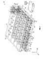
FIG. 1 is an illustration of the disclosed micro-concentrator solar array including a plurality of solar cells arranged on a coverglass and a plurality of micro-electromechanical systems (MEMS) based reflectors arranged on a substrate; -
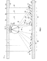
FIG. 2 is a cross-section of the micro-concentrator solar array taken along section line A-A inFIG. 1 ; -
FIG. 3 is a perspective view of a portion of the coverglass shown inFIG. 1 , where receivers may be used to mount the solar cells to the coverglass; -
FIG. 4 is an exemplary process flow diagram illustrating a method of adjusting the reflectors shown inFIG. 1 ; and -
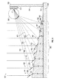
FIG. 5 is an illustration of an alternative aspect of the micro-concentrator solar array. - As shown in
FIG. 1 , the micro-concentratorsolar array 10 according to an aspect of the disclosure may include acoverglass 20, a plurality ofsolar cells 22, asubstrate 24, a plurality of micro-electromechanical systems (MEMS) based mirrors orreflectors 30, and acontrol module 32. In the exemplary aspect as shown, thesolar cells 22 may be arranged in a 5x5 array upon thecoverglass 20, which results in a total of twenty-fivesolar cells 22 included within the micro-concentratorsolar array 10. However, those skilled in the art will appreciate that thesolar array 10 may include any number ofsolar cells 22. Anarray 40 ofreflectors 30 may be associated with eachsolar cell 22. Eachreflector 30 included within thearray 40 may be positioned relative to the associatedsolar cell 22 in order to focus or reflect a plurality oflight beams 42 generated by a light source (not illustrated) onto thesolar cell 22. - The light source may be any type of radiating energy source such as, for example, man-made lighting in a building, or the sun. Each
reflector 30 may be selectively tiltable such that if the position of the light source changes, eachreflector 30 located within theassociated array 40 may be tilted accordingly in order to track the changed position of the light source relative to the associatedsolar cell 22. For example, if the light source is the sun, then eachreflector 30 located within the associatedarray 40 may be tilted accordingly in order to track the changing position of the sun throughout the day. The tilting of thereflectors 30 relative to the light source is described in greater detailed below. - The micro-concentrator
solar array 10 may be used in any application where light energy, typically from the sun, may be converted into electrical energy. For example,FIG. 1 illustrates a single micro-concentratorsolar array 10 for purposes of convenience and clarity. The single micro-concentratorsolar array 10 inFIG. 1 may be used in relatively compact applications such as, for example, a slim-line pocket-sized portable power generator. However, the single micro-concentratorsolar array 10 may be electrically connected or ganged with other micro-concentrator solar arrays in order to create a two-dimensional or tiled array of multiple micro-concentrator arrays (not illustrated). The two-dimensional array of multiple micro-concentrator arrays may be used in relatively large-scale applications such as, for example, a terrestrial portable power generator, an unmanned aerial vehicle (UAV), or a satellite. - The
coverglass 20 may be constructed of any transparent material that allows for the light beams 42 to pass through such as, for example, glass, plastic, or silicon dioxide. Thesubstrate 24 may be used to support or mount thereflectors 30. In one non-limiting aspect, thesubstrate 24 may be constructed of fused silica. -
FIG. 2 is a cross-section of a portion of thecoverglass 20, a singlesolar cell 22, thesubstrate 24, and thereflectors 30 associated with the singlesolar cell 22, taken along section line A-A inFIG. 1 . Referring generally toFIGS. 1-2 , thecoverglass 20 may include anouter surface 50 and aninner surface 52, and thesubstrate 24 may also include anouter surface 54 and aninner surface 56. In one aspect, an optional anti-reflection coating may be applied to the inner andouter surfaces coverglass 20. Theinner surface 52 of thecoverglass 20 generally opposes theinner surface 56 of thesubstrate 24. Eachsolar cell 22 may include afront surface 60 and a back surface 63 (seen inFIG. 2 ). Theback surface 63 of thesolar cell 22 may be affixed to or carried by theinner surface 52 of thecoverglass 20. - Although
FIGS. 1-2 show thecoverglass 20 located above thesubstrate 24, it is to be understood that this illustration is merely exemplary in nature. Those skilled in the art will appreciate that thecoverglass 20 may be located relative to thesubstrate 24 in any position where the light beams 42 may be directed upon thereflectors 30 and onto thesolar cells 22. For example, in another aspect, the micro-concentratorsolar array 10 may be rotated by ninety degrees, and thecoverglass 20 may be located to the right of thesubstrate 24. Moreover, in some aspects thecoverglass 20 may be omitted. Instead, thesolar cells 22 may be mounted on acorresponding support member 320 shown inFIG. 5 , and is described in greater detail below. - Referring to
FIG. 1 , in one aspect thereflectors 30 may be arranged in a two-dimensional pattern upon theinner surface 56 of thesubstrate 24. Specifically, eacharray 40 may includemultiple sub-arrays 64 ofreflectors 30. In the aspect as shown inFIG. 1 , each sub-array 64 may include fourreflectors 30, however it is to be understood that any number ofreflectors 30 may be included within the sub-array 64 as well. In the non-limiting aspect as shown inFIG. 1 , each sub-array 64 ofreflectors 30 may be arranged in a radially outward direction with respect to a central point C of thearray 40. The specificsolar cell 22 associated with thearray 40 may be positioned along theinner surface 52 of thecoverglass 20 to generally oppose the central point C. AlthoughFIG. 1 illustrates each sub-array 64 ofreflectors 30 arranged in a radially outward direction, those skilled in the art will appreciate that this illustration is merely exemplary in nature. For example, in another aspect, thereflectors 30 may be arranged in a rectangular pattern. - The
solar cells 22 may also be referred to as photovoltaic cells. Thesolar cells 22 may be any device configured to convert solar radiation into electrical energy. In one exemplary aspect, the micro-concentratorsolar array 10 may include a secondaryoptical device 62 associated with eachsolar cell 22. However, it is to be understood that the secondaryoptical device 62 may be omitted in some aspects. Referring toFIG. 2 , the secondaryoptical device 62 may be positioned along thefront surface 60 of thesolar cell 22. The secondaryoptical device 62 may be used to focus the light beams 42 reflected off of each reflection surface 58 of thereflectors 30 and onto a focal point F located on thesolar cell 22. Thus, thesolar cell 22 may receive an increased amount of light energy if the secondaryoptical device 62 is included. The secondaryoptical device 62 may be any type of concentrator or lens for focusing light from thereflectors 30 onto the focal point F of thesolar cell 22 such as, for example, a concave lens, a convex lens, a parabolic lens, or a Fresnel lens. -
FIG. 3 illustrates a portion of theinner surface 52 of thecoverglass 20, where thecoverglass 20 has been rotated one hundred and eighty degrees such that theinner surface 52 of thecoverglass 20 is facing upwardly. In the aspect as shown inFIG. 3 , thesolar cells 22 are each mounted to and electrically connected to a correspondingreceiver 70. Eachreceiver 70 may be mounted to theinner surface 52 of thecoverglass 20. Thereceivers 70 may be used as an alternative approach for mounting thesolar cells 22 to thecoverglass 20. In one aspect, thereceivers 70 may include a heat sink or other device (not illustrated) for dissipating heat generated by thesolar cell 22. - A plurality of
interconnects 72 may be used to electrically connect two or more of thereceivers 70 to one another. In one aspect, theinterconnects 72 may be constructed from an electrically conductive material such as, for example, metal. Theinterconnects 72 may be located along theinner surface 52 of thecoverglass 20, and may be used to electrically connect thereceivers 70 in any number of configurations in order to provide the voltage and current required for a specific application. For example, in the aspect as shown inFIG. 3 , theinterconnects 72 may be used to connect thereceivers 70 located in asingle row 75 to one another in a series configuration. However, theinterconnects 72 may also be used to connect eachrow 75 ofreceivers 70 to one another in a parallel configuration (the parallel connection is not illustrated inFIG. 3 ). AlthoughFIG. 3 illustrates thereceivers 70 located in eachrow 75 connected to one another in a series configuration, it is to be understood that thereceivers 70 may be connected to one another in a parallel configuration as well. Moreover, although eachrow 75 ofreceivers 70 are described as being connected to one another in a parallel configuration, it is to be understood that therows 75 ofreceivers 70 may be connected together in a series configuration as well. - Referring to
FIG. 2 , thereflectors 30 may be any type of MEMS-based device having an elliptical, cylindrical, rectangular, square, or randomly shaped micro-mirror or micro-reflector configured to reflect light. An actuation device (not illustrated) may be provided for eachreflector 30. The actuation device may be used to adjust an amount of tilt of an associatedreflector 30. Specifically, as seen inFIG. 2 , the amount of tilt of each reflector may be measured by an angle α. The angle α may be measured between thereflection surface 58 of thereflector 30 and an axis A-A. The axis A-A may be oriented generally parallel with respect to thesubstrate 24. A reflectedlight beam 80 may represent the light reflected off of thereflection surface 58 of thereflector 30 and directed towards the secondaryoptical device 62. If the secondaryoptical device 62 is omitted, then the reflectedlight beam 80 may be directed towards the focal point F located on thesolar cell 22. It should be noted that while thereflector 30 is described as being tiltable or rotatable in the x-axis direction (the x-axis is illustrated inFIG. 1 ), thereflector 30 may be tilted about a second axis of rotation as well. Specifically, in one aspect, the angle α of thereflector 30 may be tilted in the z-axis direction (the z-axis is illustrated inFIG. 1 ) as well. Thus, thereflector 30 may be tilted using either single-axis tracking (i.e., adjusted in either the x-axis or the z-axis) or dual-axis tracking (i.e., adjusted in both the x-axis and the z-axis). In other words, the reflectors may be tiltable or rotatable about either one axis of rotation or two axes of rotation. - The actuation device (not illustrated) may be any type of device capable of adjusting the angle α of the associated
reflector 30. For example, in one non-limiting aspect, the actuating devices may be comb-drive actuators that use static electromagnetic potential for actuation. In another aspect, the actuating devices may be a rotational actuator. One commercially available example of the rotational actuator is the 4-quadrant 2-axis actuators manufactured by Mirrorcle Technologies of Richmond, California. - Referring to both
FIGS. 1-2 , the angle α of thereflectors 30 may be adjusted by applying a specific or unique amount of voltage to each of the actuation devices (not illustrated). For example, with reference toFIG. 2 , the reflector R1 located to the far right may be tilted at a different angle α when compared to the angles α of the remaining reflectors R2, R3 and R4 located within the sub-array 64. Eachreflector 30 may be tilted at a different angle α based on the reflector's 30 position relative to the focal point F of the correspondingsolar cell 22. Thus, a unique amount of voltage may be applied to the actuation device associated with eachreflector 30 in order to tilt eachreflector 30 by a specific amount. - In one approach, the
control module 32 may have a voltage-tilt curve stored in memory. In one aspect, the voltage-tilt curve may be stored in memory as either a lookup table or a polynomial fit to voltage-tilt data. The voltage-tilt curve may include a plurality of unique voltage values that are each associated with different values of the angle α of thereflector 30. It should be noted that the voltage-tilt curve may be common to all of thereflectors 30 located within the micro-concentratorsolar array 10. The memory of thecontrol module 32 may also store the position of all of thereflectors 30 relative to the correspondingsolar cell 22 as well. - The
control module 32 may determine the unique amount of voltage applied to eachreflector 30 using the using the following approach. First, thecontrol module 32 may calculate the angle α of thereflectors 30. In the example as described, thecontrol module 32 calculates the angle α of the reflector R1 to the far right as shown inFIG. 2 . Thecontrol module 32 may calculate the angle α of the reflector R1 based on the position of the reflector R1 relative to the corresponding solar cell 22 (stored in memory of the control module 32), and an angle θ of the light beams 42. The angle θ of the light beams 42 may be measured with respect to thecoverglass 20. The angle θ of the light beams 42 may be a known value stored in memory of thecontrol module 32. The value of the angle θ of the light beams 42 stored in memory may be updated as the position of a light source (e.g., the sun) changes. Once thecontrol module 32 calculates the angle α of the reflector R1, thecontrol module 32 may then obtain the unique amount of voltage applied to the reflector R1 using the voltage tilt-curve. For example, if thecontrol module 32 determines that the angle α of the reflector R1 should be fifteen degrees, then thecontrol module 32 obtains the unique amount of voltage associated with an angle of fifteen degrees from the voltage-tilt curve stored in memory of thecontrol module 32. Finally, thecontrol module 32 may apply the unique amount of voltage obtained from the voltage-tilt curve to the actuation device associated with the reflector R1. - Referring to
FIGS. 1-3 , thecontrol module 32 may refer to, or be part of, an application specific integrated circuit (ASIC), an electronic circuit, a combinational logic circuit, a field programmable gate array (FPGA), a processor (shared, dedicated, or group) that executes code, or a combination of some or all of the above, such as in a system-on-chip. Thecontrol module 32 may be in operative communication with each of thesolar cells 22 and thereflectors 30. Specifically, thecontrol module 32 may be in communication with all of thesolar cells 22 located within the micro-concentratorsolar array 10 through theinterconnects 72 located along thecoverglass 20 shown inFIG. 3 (the connection between theinterconnects 72 and thecontrol module 32 is not illustrated in the figures). - The
control module 32 may include control logic for monitoring the electrical output generated by all of thesolar cells 22 located within the micro-concentratorsolar array 10. The electrical output measured by thecontrol module 32 may be, for example, voltage, current, or power generated by thesolar cells 22. Thecontrol module 32 may monitor the electrical output generated by all of thesolar cells 22 located within the micro-concentratorsolar array 10 at a predetermined time interval. The predetermined time interval may be any set amount of time such as, for example, every thirty seconds, every minute, or every five minutes. - In the illustration as shown in
FIG. 2 , thereflectors 30 are tilted at their ideal angles α such that the reflected light beams 80 are each directed towards the focal point F located on thesolar cell 22. Thecontrol module 32 may store an ideal output value within memory. The ideal output value represents the electrical output of the solar cells 22 (e.g., voltage, current, power, etc.) when thereflectors 30 are tilted at their ideal angles.FIG. 2 illustrates the light source (e.g., the sun) directing the light beams 42 in a direction generally perpendicular to thecoverglass 20 and thesubstrate 24. However, as the sun moves throughout the sky throughout the day, the direction of the light beams 42 change accordingly. Thus, the position of the light beams 80 reflected off of thereflection surface 58 of eachreflector 30 may also change. As a result, the reflected light beams 80 are eventually reflected away from the focal point F of the correspondingsolar cell 22. Focusing light upon the focal point F of a correspondingsolar cell 22 may maximize the amount of electrical output generated by thesolar cell 22. As the reflected light beams 80 are directed away from the focal point F of the correspondingsolar cell 22, less light energy may be received by thesolar cell 22. As a result, the electrical output generated by thesolar cell 22 is decreased. - Referring to
FIGS. 1-2 , thecontrol module 32 monitors the electrical output generated by all of thesolar cells 22 located within the micro-concentratorsolar array 10 at the predetermined time interval. Thecontrol module 32 also includes control logic for comparing the electrical output generated by thesolar cells 22 with a threshold value. The threshold value may represent an electrical output generated by all of thesolar cells 22 that is less than the ideal output value. For example, in one non-limiting aspect, the threshold value may be about ninety-five percent of the ideal output value. - The
control module 32 may include circuitry or control logic for applying the unique amount of voltage to each of the actuation devices (not illustrated) associated with thereflectors 30 if the electrical output generated by all of thesolar cells 22 is below the threshold value. Specifically, once the electrical output generated by thesolar cells 22 drops below a threshold value, then thecontrol module 32 may apply the unique amount of voltage to each of the actuation devices (not illustrated). Thereflectors 30 may be repositioned such that the light beams 80 reflected off of thereflection surface 58 of eachreflector 30 may be directed back towards the focal point F of the correspondingsolar cell 22. In one aspect, thecontrol module 32 may include control logic for re-positioning thereflectors 30 towards the focal point F of the correspondingsolar cell 22 by first stepping through a plurality of pre-programmed reflector positions stored in memory. Each pre-programmed reflector position corresponds with a specific position of the light source. For example, if the light source is the sun, then each pre-programmed reflector position stored in memory of thecontrol module 32 may correspond with the different positions of the sun in the sky. Thecontrol module 32 may step though the pre-programmed reflector positions until thereflectors 30 align and focus the light beams 80 towards the focal point F of thesolar cell 22. -
FIG. 4 is a process flow diagram illustrating anexemplary method 200 of adjusting the tilt of thereflectors 30. Referring generally toFIGS. 1-4 ,method 200 may begin atblock 202, where thecontrol module 32 monitors the electrical output generated by all of thesolar cells 22 located within the micro-concentratorsolar array 10. The electrical output measured by thecontrol module 32 may be, for example, voltage, current, or power generated by thesolar cells 22.Method 200 may then proceed to block 204. - In
block 204, thecontrol module 32 compares the electrical output generated by all of thesolar cells 22 located within the micro-concentratorsolar array 10 with the threshold value. If the electrical output is equal to or greater than the threshold value, thenmethod 200 may then terminate. However, if the electrical output is less than the threshold value, thenmethod 200 may proceed to block 206. - In
block 206, thecontrol module 32 may apply the unique amount of voltage to each of the actuation devices (not illustrated). As discussed above, applying the unique amount of voltage to each of the actuation devices may re-position each of thereflectors 30 such that the light beams 80 reflected off of thereflection surface 58 of eachreflector 30 may be directed back towards the focal point F of the correspondingsolar cell 22.Method 200 may then return to block 202. -
FIG. 5 is a cross-section of an alternative aspect of a micro-concentratorsolar array 300, illustrating a singlesolar cell 322 and a sub-array 364 ofreflectors 330 associated with thesolar cell 322. In the aspect as shown inFIG. 5 , thereflectors 330 may be supported by asubstrate 324. Acorresponding support member 320 may be attached or otherwise affixed to thesubstrate 324. Specifically, thesupport member 320 includes afirst end 350 and asecond end 352. Thefirst end 350 of thesupport member 320 may be affixed to thesubstrate 324. Thesolar cell 322 may be affixed to thesecond end 352 of thesupport member 320. It should be noted that the aspect as shown inFIG. 5 does not require a coverglass, and instead thesupport member 320 may be used to carry thesolar cell 322. AlthoughFIG. 5 illustrates a singlesolar cell 322, those skilled in the art will appreciate that thesolar cell 322 may be part of an array of multiple solar cells. For example, thesubstrate 324 may includemultiple support members 320. Eachsupport member 320 may carry asolar cell 322. Also, whileFIG. 5 illustrates asingle sub-array 364 of thereflectors 330, it is to be understood thatmultiple sub-arrays 364 ofreflectors 330 may surround thesolar cell 322. - The
substrate 324 may include a ramped or inclinedinner surface 360. Thereflectors 330 may be positioned along theinner surface 360 of thesubstrate 324. In the non-limiting aspect as shown, the sub-array 364 includes eight reflectors R1'-R8', where the reflector R1' may be thereflector 330 located the furthest away from thesolar cell 322, and the reflector R8' may be thereflector 330 located closest to thesolar cell 322. Theinner surface 360 of thesubstrate 324 may be angled such that the reflector R1' may be positioned at a vertical height H1, the reflector R2' may be positioned at a vertical height H2, and the remaining reflectors R3'-R8' may be positioned accordingly. - The vertical heights H1-H8 of the reflectors R1'-R8' may be graduated accordingly such that light reflected off of one of the
reflectors 330 in the sub-array 364 does not generally interfere with anotherreflector 330 located downstream. For example, the vertical height H1 of the reflector R1' is greater than the vertical heights of the remaining reflectors R2'-R8'. Thus, the reflector R1' may be elevated such that a beam oflight 380 reflected off areflection surface 358 of the reflector R1' does not interfere or intersect with any of the remaining reflectors R2'-R8' located within the sub-array 364. Instead, the beam oflight 380 reflected off thereflection surface 358 may be directed towards a secondaryoptical device 362 and onto a focal point F' located on thesolar cell 322. - Referring generally to
FIG. 1-5 , the disclosed micro-concentratorsolar array 10 provides a relatively compact and efficient approach for converting light into electrical energy. In particular, the disclosed micro-concentratorsolar array 10 provides an approach for adjusting the MEMS based reflectors (e.g., thereflectors 30 shown inFIGS. 1-3 or thereflectors 330 shown inFIG. 5 ) based on the position of a moving light source (not illustrated). For example, if the light source is the sun, the reflectors may track the position of the sun throughout the sky. The reflectors may then reflect the light from the sun onto the focal point of a corresponding solar cell. Therefore, if the micro-concentratorsolar array 10 is part of a solar power generator, then a user does not generally need to re-position the solar power generator periodically during the day in order to accommodate the changing position of the sun within the sky. Moreover, many solar power generators currently available employ flat-plate technologies, where the solar cells operate under 1-sun concentration. In contrast, the disclosed micro-concentratorsolar array 10 uses the reflectors in order to concentrate light onto the solar cells. In one aspect, the disclosed solar cells may operate between about 5-suns to about 500-suns concentration. Thus, the disclosed micro-concentratorsolar array 10 may employ smaller solar cells that require less space. The disclosedmicro-concentrator array 10 may also provide higher solar-to-power conversion efficiencies, and transform less of light energy into heat when compared to the technologies currently available. - While the forms of apparatus and methods herein described constitute preferred aspects of this invention, it is to be understood that the invention is not limited to these precise forms of apparatus and methods, and the changes may be made therein without departing from the scope of the invention.
Claims (15)
- A micro-concentrator solar array, comprising:a plurality of solar cells 22, wherein each solar cell 22 includes a focal point; anda plurality of micro-electromechanical systems (MEMS) based reflectors 30, wherein the MEMS based reflectors 30 are each selectively tiltable about at least one axis to reflect a beam of light onto the focal point of one of the solar cells 22.
- The micro-concentrator solar array of claim 1, further comprising a control module 32 in operative communication with the solar cells 22 and the MEMS based reflectors 30.
- The micro-concentrator solar array of claim 2, wherein the control module 32 includes control logic for monitoring an electrical output generated by the solar cells 22.
- The micro-concentrator solar array of claim 3, wherein the control module 32 includes control logic for determining if the electrical output generated by the solar cells 22 is below a threshold value.
- The micro-concentrator solar array of claim 4, wherein the control module 32 includes control logic for re-positioning the MEMS based reflectors 30 about the at least one axis if the electrical output generated by the solar cells 22 is below the threshold value.
- The micro-concentrator solar array of claim 1, wherein the solar cells 22 are mounted upon a coverglass 20.
- The micro-concentrator solar array of claim 6, comprising a plurality of receivers 70 mounted to the coverglass 20, wherein the receivers are each associated with one of the solar cells 22, and wherein the solar cells 22 are each mounted to and electrically connected to a corresponding receiver 70.
- The micro-concentrator solar array of claim 1, wherein the MEMS based reflectors 30 are mounted upon a substrate 24.
- The micro-concentrator solar array of claim 8, optionally comprising a plurality of support members 320 affixed to the substrate 324, wherein each solar cell is supported by a corresponding support member 320.
- The micro-concentrator solar array of claim 1, wherein the MEMS based reflectors 30 are each selectively tiltable about two axes of rotation to reflect a beam of light onto the focal point of a corresponding solar cell 22.
- A method of tracking light onto a solar cell, wherein the solar cell is part of a micro-concentrator solar array, the method comprising:monitoring an electrical output generated by a plurality of solar cells by a control module [process 202];determining if the electrical output generated by the solar cells is below a threshold value by the control module [process 204]; andre-positioning a plurality of micro-electromechanical systems (MEMS) based reflectors about at least one axis if the electrical output generated by the solar cells is below the threshold value by the control module, wherein each of the MEMS based reflectors are selectively tiltable about the at least one axis to reflect a beam of light onto a focal point of one of the solar cells [process 206].
- The method as recited in claim 11, comprising mounting the solar cells 22 upon a coverglass 20.
- The method as recited in claim 12, wherein a plurality of receivers 70 are mounted to the coverglass 20, wherein the receivers 70 are each associated with one of the solar cells 22, and wherein the solar cells 22 are each mounted to and electrically connected to a corresponding receiver 70.
- The method as recited in claim 11, optionally comprising mounting the MEMS based reflectors 330 and a plurality of support members 320 upon a substrate 324, wherein each solar cell 322 is supported by a corresponding support member 320.
- The method as recited in claim 11, comprising applying a unique amount of voltage by the control module 32 in order to re-position the MEMS based reflectors 30, wherein the unique amount of voltage is based on a voltage-tilt curve stored in a memory of the control module 32.
Applications Claiming Priority (1)
| Application Number | Priority Date | Filing Date | Title |
|---|---|---|---|
| US14/186,703 US10693028B2 (en) | 2014-02-21 | 2014-02-21 | Micro-concentrator solar array using micro-electromechanical systems (MEMS) based reflectors |
Publications (2)
| Publication Number | Publication Date |
|---|---|
| EP2911208A1 true EP2911208A1 (en) | 2015-08-26 |
| EP2911208B1 EP2911208B1 (en) | 2018-08-29 |
Family
ID=52339044
Family Applications (1)
| Application Number | Title | Priority Date | Filing Date |
|---|---|---|---|
| EP15150912.2A Active EP2911208B1 (en) | 2014-02-21 | 2015-01-13 | Micro-concentrator solar array using micro-electromechanical systems (MEMS) based reflectors |
Country Status (4)
| Country | Link |
|---|---|
| US (1) | US10693028B2 (en) |
| EP (1) | EP2911208B1 (en) |
| JP (1) | JP6591753B2 (en) |
| CA (1) | CA2878660C (en) |
Cited By (6)
| Publication number | Priority date | Publication date | Assignee | Title |
|---|---|---|---|---|
| EP3018822A1 (en) * | 2014-11-04 | 2016-05-11 | The Boeing Company | Micro-concentrator solar array using micro- electromechanical systems (mems) based |
| EP3208853A1 (en) * | 2016-02-18 | 2017-08-23 | The Boeing Company | Micro-concentrator module and deployment method |
| US9813022B2 (en) | 2014-02-21 | 2017-11-07 | The Boeing Company | Dynamically setting a threshold output level for a solar array |
| CN107643769A (en) * | 2017-07-31 | 2018-01-30 | 东南大学 | A solar focus tracking device and sun position monitoring method |
| US10236822B2 (en) | 2014-02-21 | 2019-03-19 | The Boeing Company | Method and apparatus for calibrating a micro-concentrator solar array |
| US10250182B2 (en) | 2014-02-21 | 2019-04-02 | The Boeing Company | Micro-concentrator solar array using micro-electromechanical systems (MEMS) based reflectors |
Families Citing this family (6)
| Publication number | Priority date | Publication date | Assignee | Title |
|---|---|---|---|---|
| US10790776B2 (en) | 2016-02-01 | 2020-09-29 | The Boeing Company | System and method for controlling the power ratio of a solar concentrator array |
| CN106202837B (en) * | 2016-08-26 | 2019-07-12 | 哈尔滨工业大学深圳研究生院 | A method of the small satellite constellation remote sensing system model based on unmanned plane auxiliary covering |
| US10930806B2 (en) | 2016-12-05 | 2021-02-23 | The Boeing Company | Thermal management system for controlling the temperature of a reflective surface having a solar concentrator array |
| CN108928479A (en) * | 2018-06-28 | 2018-12-04 | 山东浩坤安全技术咨询有限公司 | A kind of rotor wing unmanned aerial vehicle with solar recharging |
| US20220407453A1 (en) * | 2021-01-29 | 2022-12-22 | Purdue Research Foundation | Lightweight passive radiative cooling to enhance concentrating photovoltaics |
| CN113377132A (en) * | 2021-05-07 | 2021-09-10 | 青岛科技大学 | Intelligent glass plate of MEMS (micro-electromechanical system) micro-mirror array for tracking and condensing light |
Citations (6)
| Publication number | Priority date | Publication date | Assignee | Title |
|---|---|---|---|---|
| DE29615560U1 (en) * | 1996-08-27 | 1997-02-20 | Waldorf, Volker, 56599 Leutesdorf | Solar module consisting of the combination of solar cells from photovoltaics and the collector (absorber) of solar thermal systems, as well as the light supply via mirrors |
| US20090188545A1 (en) * | 2008-01-30 | 2009-07-30 | Mario Rabinowitz | Tracking and focusing adjustable fresnel lens array solar concentrator |
| WO2009126263A1 (en) * | 2008-04-08 | 2009-10-15 | Cornell University | Multi-axis, large tilt angle, wafer level micromirror array for large scale beam steering applications |
| WO2010065794A2 (en) * | 2008-12-03 | 2010-06-10 | James Hoffman | Solar energy collection system |
| US20100192941A1 (en) * | 2009-01-30 | 2010-08-05 | Stoia Michael F | Solar Concentration System With Micro-Mirror Array |
| DE102009037083A1 (en) * | 2009-08-11 | 2011-02-17 | Bayerische Solar Ag | Photovoltaic device for use in solar system utilized for converting solar energy into electrical energy, has mirrors provided with reflected surfaces, respectively, and control unit controlling rotation of mirrors about rotational axis |
Family Cites Families (72)
| Publication number | Priority date | Publication date | Assignee | Title |
|---|---|---|---|---|
| US412724A (en) | 1889-10-15 | William calver | ||
| US503004A (en) | 1893-08-08 | severy | ||
| US629122A (en) | 1899-03-20 | 1899-07-18 | Charles A Davis | Solar water-heater. |
| US811274A (en) | 1904-01-06 | 1906-01-30 | Solar Furnace And Power Co | Solar furnace. |
| US2846724A (en) | 1956-07-13 | 1958-08-12 | Thomas C Aylwin | Solar reflection device and means for producing the same |
| US2987961A (en) | 1958-04-17 | 1961-06-13 | Eugene S Cotton | Solar furnace |
| US3466119A (en) | 1965-04-10 | 1969-09-09 | Giovanni Francia | Multiple mirrored apparatus utilizing solar heat |
| US3713727A (en) | 1971-04-22 | 1973-01-30 | Erevanskoe Otdel V Ni P Konstr | Solar unit |
| US3905352A (en) | 1973-08-31 | 1975-09-16 | Arnold Jahn | System for collecting and transferring usable solar heat |
| US3861379A (en) | 1974-03-05 | 1975-01-21 | Jr Henry Anderson | Low profile solar ray concentrator |
| GB1513402A (en) | 1974-06-21 | 1978-06-07 | Kume T | Solar boilers |
| US3964464A (en) | 1975-04-08 | 1976-06-22 | Oak Ridge Solar Engineering, Inc. | Solar radiation collector and concentrator |
| US4038971A (en) | 1975-10-22 | 1977-08-02 | Bezborodko Joseph A I B | Concave, mirrored solar collector |
| US4106480A (en) | 1975-12-15 | 1978-08-15 | Halm Instrument Co., Inc. | Reflective solar heat collector |
| US4044753A (en) | 1976-04-28 | 1977-08-30 | Nasa | Solar energy collection system |
| US4198826A (en) | 1976-10-26 | 1980-04-22 | Edsel Chromie | Solar powered engine and tracking system |
| US4046411A (en) | 1976-12-01 | 1977-09-06 | General Motors Corporation | Impact energy absorbing mounting unit for mounting an automotive vehicle bumper assembly |
| US4318393A (en) | 1976-12-06 | 1982-03-09 | The Regents Of The University Of Minnesota | Porous surface solar energy receiver |
| US4110010A (en) | 1977-07-07 | 1978-08-29 | Hilton Richard D | Ganged heliostat |
| US4263895A (en) | 1977-10-17 | 1981-04-28 | Sanders Associates, Inc. | Solar energy receiver |
| US4249514A (en) | 1978-03-09 | 1981-02-10 | Westinghouse Electric Corp. | Tracking solar energy concentrator |
| US4405010A (en) | 1978-06-28 | 1983-09-20 | Sanders Associates, Inc. | Sensible heat storage unit |
| US4235224A (en) | 1978-09-20 | 1980-11-25 | Bunk Edward R | Solar heat collector block |
| US4243019A (en) | 1978-10-25 | 1981-01-06 | Honeywell Inc. | Light-weight-trough type solar concentrator shell |
| US4262660A (en) | 1979-08-02 | 1981-04-21 | Ilich Daniel F | Solar cooker |
| US4343294A (en) | 1979-10-26 | 1982-08-10 | Daniel Jack H | Solar collector assembly |
| US4463749A (en) | 1982-03-08 | 1984-08-07 | Ford Aerospace & Communications Corporation | Modular solar concentrator |
| IL65238A (en) | 1982-03-14 | 1987-01-30 | Naaman Ben Aharon | Linear concentrating solar collector |
| US4599995A (en) | 1984-11-07 | 1986-07-15 | Dane John A | Linear collector for a parabolic reflector |
| US4784700A (en) | 1987-05-26 | 1988-11-15 | General Dynamics Corp./Space Systems Div. | Point focus solar concentrator using reflector strips of various geometries to form primary and secondary reflectors |
| US4825062A (en) | 1987-10-29 | 1989-04-25 | Kaman Aerospace Corporation | Extendable large aperture phased array mirror system |
| US5109349A (en) | 1990-01-23 | 1992-04-28 | Kaman Aerospace Corporation | Actively controlled segmented mirror |
| US5071243A (en) | 1990-03-19 | 1991-12-10 | Bronstein Allen I | Tensioned cover for parabolic reflector |
| US5325844A (en) | 1992-02-11 | 1994-07-05 | Power Kinetics, Inc. | Lightweight, distributed force, two-axis tracking, solar radiation collector structures |
| US5269288A (en) | 1993-06-02 | 1993-12-14 | Stirbl Robert C | Method and apparatus for generating atmospheric solar energy concentrator |
| IL114261A0 (en) | 1995-06-22 | 1995-10-31 | Yeda Res & Dev | System for control of heliostat field |
| US6028689A (en) | 1997-01-24 | 2000-02-22 | The United States Of America As Represented By The Secretary Of The Air Force | Multi-motion micromirror |
| JP2951297B2 (en) | 1997-10-15 | 1999-09-20 | 三鷹光器株式会社 | Solar concentrator system |
| US6091050A (en) | 1997-11-17 | 2000-07-18 | Roxburgh Limited | Thermal microplatform |
| US6458231B1 (en) | 1999-03-17 | 2002-10-01 | The United States Of America As Represented By The Secretary Of The Air Force | Method of making microtubes with axially variable geometries |
| US6356383B1 (en) | 1999-04-02 | 2002-03-12 | Corvis Corporation | Optical transmission systems including optical amplifiers apparatuses and methods |
| US6225551B1 (en) | 1999-09-02 | 2001-05-01 | Midwest Research Institute | Multi-facet concentrator of solar setup for irradiating the objects placed in a target plane with solar light |
| US6231197B1 (en) | 2000-03-20 | 2001-05-15 | Mitaka Kohkico., Ltd. | Heliostat for sunlight collecting system |
| US6542657B2 (en) | 2000-12-20 | 2003-04-01 | Network Photonics, Inc. | Binary switch for an optical wavelength router |
| JP3701264B2 (en) | 2002-07-05 | 2005-09-28 | 三鷹光器株式会社 | Heliostat for solar condensing system and control method thereof |
| AU2002950582A0 (en) | 2002-08-05 | 2002-09-12 | Robert Edgar Whelan | Dish assembly |
| US7019434B2 (en) | 2002-11-08 | 2006-03-28 | Iris Ao, Inc. | Deformable mirror method and apparatus including bimorph flexures and integrated drive |
| US6906848B2 (en) | 2003-02-24 | 2005-06-14 | Exajoule, Llc | Micromirror systems with concealed multi-piece hinge structures |
| US6959993B2 (en) * | 2003-07-10 | 2005-11-01 | Energy Innovations, Inc. | Solar concentrator array with individually adjustable elements |
| DE10358967B4 (en) | 2003-12-15 | 2006-11-16 | Universität Kassel | Micromirror array |
| US6988809B2 (en) | 2004-01-16 | 2006-01-24 | Mario Rabinowitz | Advanced micro-optics solar energy collection system |
| JP2005217171A (en) | 2004-01-29 | 2005-08-11 | Daido Steel Co Ltd | Method for adjusting angle of reflector in condensation type photovoltaic power generation apparatus |
| KR100583745B1 (en) | 2004-01-30 | 2006-06-08 | (주)솔레이텍 | Charging method and device using portable multi-power solar cell |
| US7905227B2 (en) | 2004-03-30 | 2011-03-15 | Energy Innovations, Inc. | Self-ballasting solar collector |
| US7777959B2 (en) | 2004-05-27 | 2010-08-17 | Angstrom, Inc. | Micromirror array lens with fixed focal length |
| US7677241B2 (en) | 2004-09-22 | 2010-03-16 | Energy Innovations, Inc. | Apparatus for redirecting parallel rays using rigid translation |
| JP4335114B2 (en) | 2004-10-18 | 2009-09-30 | 日本碍子株式会社 | Micromirror device |
| JP4721255B2 (en) * | 2004-11-04 | 2011-07-13 | 株式会社リコー | Optical deflection device array and image projection display device |
| US8528541B2 (en) | 2005-01-31 | 2013-09-10 | Seesean, Inc. | Solar collection apparatus and methods |
| US7741557B2 (en) * | 2005-12-19 | 2010-06-22 | Corning Incorporated | Apparatus for obtaining radiant energy |
| US20070236773A1 (en) | 2006-04-06 | 2007-10-11 | Pan Shaoher X | High-resolution scanning display system |
| US7782514B2 (en) | 2006-07-18 | 2010-08-24 | Jds Uniphase Corporation | Pivoting micro-mirror MEMS device with a sandwiched structure and a closed cellular core |
| WO2008050354A2 (en) | 2006-10-25 | 2008-05-02 | Hilaal Alam | A nanopositioner and method to nano position an object thereof |
| US20080137172A1 (en) | 2006-12-06 | 2008-06-12 | Glimmerglass Networks, Inc. | Array of graduated pre-tilted mems mirrors |
| US8071873B2 (en) * | 2007-11-03 | 2011-12-06 | Mario Rabinowitz | Solar concentrator with induced dipole alignment of pivoted mirrors |
| US7866836B2 (en) | 2008-03-10 | 2011-01-11 | Mario Rabinowitz | Fresnel solar concentrator array with centered universal pivots |
| JP2010139991A (en) | 2008-12-15 | 2010-06-24 | Olympus Corp | Optical switch |
| DE102009004195A1 (en) * | 2009-01-09 | 2010-08-05 | Energetica Holding Gmbh | Solar module in an insulating glass composite and method of manufacture and application |
| CN106449805B (en) * | 2009-02-09 | 2019-03-12 | 艾克斯瑟乐普林特有限公司 | Concentrator type photovoltaic (CPV) module, receiver and sub-receiver and method of forming the same |
| US8238018B2 (en) | 2009-06-01 | 2012-08-07 | Zhou Tiansheng | MEMS micromirror and micromirror array |
| JP5507375B2 (en) | 2010-07-27 | 2014-05-28 | テクノナレッジ・システム有限会社 | Solar power plant |
| TWI441372B (en) | 2011-11-29 | 2014-06-11 | 沈弘濱 | Extended Mobile Power Supply |
-
2014
- 2014-02-21 US US14/186,703 patent/US10693028B2/en active Active
-
2015
- 2015-01-13 EP EP15150912.2A patent/EP2911208B1/en active Active
- 2015-01-15 CA CA2878660A patent/CA2878660C/en active Active
- 2015-01-19 JP JP2015007554A patent/JP6591753B2/en active Active
Patent Citations (6)
| Publication number | Priority date | Publication date | Assignee | Title |
|---|---|---|---|---|
| DE29615560U1 (en) * | 1996-08-27 | 1997-02-20 | Waldorf, Volker, 56599 Leutesdorf | Solar module consisting of the combination of solar cells from photovoltaics and the collector (absorber) of solar thermal systems, as well as the light supply via mirrors |
| US20090188545A1 (en) * | 2008-01-30 | 2009-07-30 | Mario Rabinowitz | Tracking and focusing adjustable fresnel lens array solar concentrator |
| WO2009126263A1 (en) * | 2008-04-08 | 2009-10-15 | Cornell University | Multi-axis, large tilt angle, wafer level micromirror array for large scale beam steering applications |
| WO2010065794A2 (en) * | 2008-12-03 | 2010-06-10 | James Hoffman | Solar energy collection system |
| US20100192941A1 (en) * | 2009-01-30 | 2010-08-05 | Stoia Michael F | Solar Concentration System With Micro-Mirror Array |
| DE102009037083A1 (en) * | 2009-08-11 | 2011-02-17 | Bayerische Solar Ag | Photovoltaic device for use in solar system utilized for converting solar energy into electrical energy, has mirrors provided with reflected surfaces, respectively, and control unit controlling rotation of mirrors about rotational axis |
Cited By (8)
| Publication number | Priority date | Publication date | Assignee | Title |
|---|---|---|---|---|
| US9813022B2 (en) | 2014-02-21 | 2017-11-07 | The Boeing Company | Dynamically setting a threshold output level for a solar array |
| US10236822B2 (en) | 2014-02-21 | 2019-03-19 | The Boeing Company | Method and apparatus for calibrating a micro-concentrator solar array |
| US10250182B2 (en) | 2014-02-21 | 2019-04-02 | The Boeing Company | Micro-concentrator solar array using micro-electromechanical systems (MEMS) based reflectors |
| EP3018822A1 (en) * | 2014-11-04 | 2016-05-11 | The Boeing Company | Micro-concentrator solar array using micro- electromechanical systems (mems) based |
| EP3208853A1 (en) * | 2016-02-18 | 2017-08-23 | The Boeing Company | Micro-concentrator module and deployment method |
| US10367449B2 (en) | 2016-02-18 | 2019-07-30 | The Boeing Company | Micro-concentrator module and deployment method |
| CN107643769A (en) * | 2017-07-31 | 2018-01-30 | 东南大学 | A solar focus tracking device and sun position monitoring method |
| CN107643769B (en) * | 2017-07-31 | 2021-05-11 | 东南大学 | A solar focusing sun chasing device and a sun position monitoring method |
Also Published As
| Publication number | Publication date |
|---|---|
| JP6591753B2 (en) | 2019-10-16 |
| US10693028B2 (en) | 2020-06-23 |
| US20150243819A1 (en) | 2015-08-27 |
| JP2015159713A (en) | 2015-09-03 |
| CA2878660A1 (en) | 2015-08-21 |
| CA2878660C (en) | 2019-06-04 |
| EP2911208B1 (en) | 2018-08-29 |
Similar Documents
| Publication | Publication Date | Title |
|---|---|---|
| EP2911208B1 (en) | Micro-concentrator solar array using micro-electromechanical systems (MEMS) based reflectors | |
| US9813022B2 (en) | Dynamically setting a threshold output level for a solar array | |
| US10236822B2 (en) | Method and apparatus for calibrating a micro-concentrator solar array | |
| US10250182B2 (en) | Micro-concentrator solar array using micro-electromechanical systems (MEMS) based reflectors | |
| Davies et al. | Design of the quartermaster solar furnace | |
| EP3018822B1 (en) | Micro-concentrator solar array using micro- electromechanical systems (mems) based | |
| US9709771B2 (en) | Light concentrator alignment system | |
| CN101496272A (en) | Planar concentrating photovoltaic solar panel with individually bonded concentrating devices | |
| AU2011270838A1 (en) | Optical control system for heliostats | |
| AU2012101946A6 (en) | Energy convertor/concentrator system | |
| EP3330635A1 (en) | Thermal management system for controlling the temperature of a reflective surface having a solar concentration array | |
| US10790776B2 (en) | System and method for controlling the power ratio of a solar concentrator array | |
| US20150236639A1 (en) | Solar receiver module for a concentrated photovoltaic (cpv) power plant | |
| US9859842B2 (en) | Device and method for testing a concentrated photovoltaic module | |
| EP3068041B1 (en) | Dynamically setting a threshold output level for a solar array | |
| WO2015104729A1 (en) | Solar concentrator and method for optimizing the irradiance of such solar concentrator | |
| KR20100046337A (en) | Condensing device for solar energy generation system and solar energy generation system using same | |
| CN101345496A (en) | Spherical mirror combination type concentration power generation apparatus | |
| EP3067938B1 (en) | Method and apparatus for calibrating a micro-concentrator solar array | |
| EP2580617A2 (en) | Low cost focussing system giving high concentrations | |
| GB2489219A (en) | Solar concentrator with orthogonal elements | |
| Liu et al. | Design of Optical Elements for Low Profile CPV Panel with Sun Tracking for Rooftop Installation | |
| Chong et al. | Optical characterization of solar furnace system using fixed geometry nonimaging focusing heliostat and secondary parabolic concentrator |
Legal Events
| Date | Code | Title | Description |
|---|---|---|---|
| PUAI | Public reference made under article 153(3) epc to a published international application that has entered the european phase |
Free format text: ORIGINAL CODE: 0009012 |
|
| AK | Designated contracting states |
Kind code of ref document: A1 Designated state(s): AL AT BE BG CH CY CZ DE DK EE ES FI FR GB GR HR HU IE IS IT LI LT LU LV MC MK MT NL NO PL PT RO RS SE SI SK SM TR |
|
| AX | Request for extension of the european patent |
Extension state: BA ME |
|
| 17P | Request for examination filed |
Effective date: 20160212 |
|
| RBV | Designated contracting states (corrected) |
Designated state(s): AL AT BE BG CH CY CZ DE DK EE ES FI FR GB GR HR HU IE IS IT LI LT LU LV MC MK MT NL NO PL PT RO RS SE SI SK SM TR |
|
| 17Q | First examination report despatched |
Effective date: 20160919 |
|
| STAA | Information on the status of an ep patent application or granted ep patent |
Free format text: STATUS: EXAMINATION IS IN PROGRESS |
|
| GRAP | Despatch of communication of intention to grant a patent |
Free format text: ORIGINAL CODE: EPIDOSNIGR1 |
|
| STAA | Information on the status of an ep patent application or granted ep patent |
Free format text: STATUS: GRANT OF PATENT IS INTENDED |
|
| INTG | Intention to grant announced |
Effective date: 20180406 |
|
| RIN1 | Information on inventor provided before grant (corrected) |
Inventor name: KRUT, DIMITRI D. Inventor name: SINGER, SCOTT B. Inventor name: KARAM, NASSER H. |
|
| GRAJ | Information related to disapproval of communication of intention to grant by the applicant or resumption of examination proceedings by the epo deleted |
Free format text: ORIGINAL CODE: EPIDOSDIGR1 |
|
| STAA | Information on the status of an ep patent application or granted ep patent |
Free format text: STATUS: EXAMINATION IS IN PROGRESS |
|
| INTC | Intention to grant announced (deleted) | ||
| GRAR | Information related to intention to grant a patent recorded |
Free format text: ORIGINAL CODE: EPIDOSNIGR71 |
|
| GRAS | Grant fee paid |
Free format text: ORIGINAL CODE: EPIDOSNIGR3 |
|
| STAA | Information on the status of an ep patent application or granted ep patent |
Free format text: STATUS: GRANT OF PATENT IS INTENDED |
|
| GRAA | (expected) grant |
Free format text: ORIGINAL CODE: 0009210 |
|
| STAA | Information on the status of an ep patent application or granted ep patent |
Free format text: STATUS: THE PATENT HAS BEEN GRANTED |
|
| INTG | Intention to grant announced |
Effective date: 20180719 |
|
| AK | Designated contracting states |
Kind code of ref document: B1 Designated state(s): AL AT BE BG CH CY CZ DE DK EE ES FI FR GB GR HR HU IE IS IT LI LT LU LV MC MK MT NL NO PL PT RO RS SE SI SK SM TR |
|
| REG | Reference to a national code |
Ref country code: GB Ref legal event code: FG4D |
|
| REG | Reference to a national code |
Ref country code: CH Ref legal event code: EP |
|
| REG | Reference to a national code |
Ref country code: AT Ref legal event code: REF Ref document number: 1036175 Country of ref document: AT Kind code of ref document: T Effective date: 20180915 |
|
| REG | Reference to a national code |
Ref country code: IE Ref legal event code: FG4D |
|
| REG | Reference to a national code |
Ref country code: DE Ref legal event code: R096 Ref document number: 602015015298 Country of ref document: DE |
|
| REG | Reference to a national code |
Ref country code: NL Ref legal event code: MP Effective date: 20180829 |
|
| REG | Reference to a national code |
Ref country code: LT Ref legal event code: MG4D |
|
| PG25 | Lapsed in a contracting state [announced via postgrant information from national office to epo] |
Ref country code: NO Free format text: LAPSE BECAUSE OF FAILURE TO SUBMIT A TRANSLATION OF THE DESCRIPTION OR TO PAY THE FEE WITHIN THE PRESCRIBED TIME-LIMIT Effective date: 20181129 Ref country code: BG Free format text: LAPSE BECAUSE OF FAILURE TO SUBMIT A TRANSLATION OF THE DESCRIPTION OR TO PAY THE FEE WITHIN THE PRESCRIBED TIME-LIMIT Effective date: 20181129 Ref country code: SE Free format text: LAPSE BECAUSE OF FAILURE TO SUBMIT A TRANSLATION OF THE DESCRIPTION OR TO PAY THE FEE WITHIN THE PRESCRIBED TIME-LIMIT Effective date: 20180829 Ref country code: NL Free format text: LAPSE BECAUSE OF FAILURE TO SUBMIT A TRANSLATION OF THE DESCRIPTION OR TO PAY THE FEE WITHIN THE PRESCRIBED TIME-LIMIT Effective date: 20180829 Ref country code: LT Free format text: LAPSE BECAUSE OF FAILURE TO SUBMIT A TRANSLATION OF THE DESCRIPTION OR TO PAY THE FEE WITHIN THE PRESCRIBED TIME-LIMIT Effective date: 20180829 Ref country code: GR Free format text: LAPSE BECAUSE OF FAILURE TO SUBMIT A TRANSLATION OF THE DESCRIPTION OR TO PAY THE FEE WITHIN THE PRESCRIBED TIME-LIMIT Effective date: 20181130 Ref country code: FI Free format text: LAPSE BECAUSE OF FAILURE TO SUBMIT A TRANSLATION OF THE DESCRIPTION OR TO PAY THE FEE WITHIN THE PRESCRIBED TIME-LIMIT Effective date: 20180829 Ref country code: RS Free format text: LAPSE BECAUSE OF FAILURE TO SUBMIT A TRANSLATION OF THE DESCRIPTION OR TO PAY THE FEE WITHIN THE PRESCRIBED TIME-LIMIT Effective date: 20180829 Ref country code: IS Free format text: LAPSE BECAUSE OF FAILURE TO SUBMIT A TRANSLATION OF THE DESCRIPTION OR TO PAY THE FEE WITHIN THE PRESCRIBED TIME-LIMIT Effective date: 20181229 |
|
| REG | Reference to a national code |
Ref country code: AT Ref legal event code: MK05 Ref document number: 1036175 Country of ref document: AT Kind code of ref document: T Effective date: 20180829 |
|
| PG25 | Lapsed in a contracting state [announced via postgrant information from national office to epo] |
Ref country code: AL Free format text: LAPSE BECAUSE OF FAILURE TO SUBMIT A TRANSLATION OF THE DESCRIPTION OR TO PAY THE FEE WITHIN THE PRESCRIBED TIME-LIMIT Effective date: 20180829 Ref country code: HR Free format text: LAPSE BECAUSE OF FAILURE TO SUBMIT A TRANSLATION OF THE DESCRIPTION OR TO PAY THE FEE WITHIN THE PRESCRIBED TIME-LIMIT Effective date: 20180829 Ref country code: LV Free format text: LAPSE BECAUSE OF FAILURE TO SUBMIT A TRANSLATION OF THE DESCRIPTION OR TO PAY THE FEE WITHIN THE PRESCRIBED TIME-LIMIT Effective date: 20180829 |
|
| PG25 | Lapsed in a contracting state [announced via postgrant information from national office to epo] |
Ref country code: EE Free format text: LAPSE BECAUSE OF FAILURE TO SUBMIT A TRANSLATION OF THE DESCRIPTION OR TO PAY THE FEE WITHIN THE PRESCRIBED TIME-LIMIT Effective date: 20180829 Ref country code: IT Free format text: LAPSE BECAUSE OF FAILURE TO SUBMIT A TRANSLATION OF THE DESCRIPTION OR TO PAY THE FEE WITHIN THE PRESCRIBED TIME-LIMIT Effective date: 20180829 Ref country code: AT Free format text: LAPSE BECAUSE OF FAILURE TO SUBMIT A TRANSLATION OF THE DESCRIPTION OR TO PAY THE FEE WITHIN THE PRESCRIBED TIME-LIMIT Effective date: 20180829 Ref country code: RO Free format text: LAPSE BECAUSE OF FAILURE TO SUBMIT A TRANSLATION OF THE DESCRIPTION OR TO PAY THE FEE WITHIN THE PRESCRIBED TIME-LIMIT Effective date: 20180829 Ref country code: CZ Free format text: LAPSE BECAUSE OF FAILURE TO SUBMIT A TRANSLATION OF THE DESCRIPTION OR TO PAY THE FEE WITHIN THE PRESCRIBED TIME-LIMIT Effective date: 20180829 Ref country code: PL Free format text: LAPSE BECAUSE OF FAILURE TO SUBMIT A TRANSLATION OF THE DESCRIPTION OR TO PAY THE FEE WITHIN THE PRESCRIBED TIME-LIMIT Effective date: 20180829 Ref country code: ES Free format text: LAPSE BECAUSE OF FAILURE TO SUBMIT A TRANSLATION OF THE DESCRIPTION OR TO PAY THE FEE WITHIN THE PRESCRIBED TIME-LIMIT Effective date: 20180829 |
|
| PG25 | Lapsed in a contracting state [announced via postgrant information from national office to epo] |
Ref country code: SK Free format text: LAPSE BECAUSE OF FAILURE TO SUBMIT A TRANSLATION OF THE DESCRIPTION OR TO PAY THE FEE WITHIN THE PRESCRIBED TIME-LIMIT Effective date: 20180829 Ref country code: SM Free format text: LAPSE BECAUSE OF FAILURE TO SUBMIT A TRANSLATION OF THE DESCRIPTION OR TO PAY THE FEE WITHIN THE PRESCRIBED TIME-LIMIT Effective date: 20180829 Ref country code: DK Free format text: LAPSE BECAUSE OF FAILURE TO SUBMIT A TRANSLATION OF THE DESCRIPTION OR TO PAY THE FEE WITHIN THE PRESCRIBED TIME-LIMIT Effective date: 20180829 |
|
| REG | Reference to a national code |
Ref country code: DE Ref legal event code: R097 Ref document number: 602015015298 Country of ref document: DE |
|
| PLBE | No opposition filed within time limit |
Free format text: ORIGINAL CODE: 0009261 |
|
| STAA | Information on the status of an ep patent application or granted ep patent |
Free format text: STATUS: NO OPPOSITION FILED WITHIN TIME LIMIT |
|
| 26N | No opposition filed |
Effective date: 20190531 |
|
| PG25 | Lapsed in a contracting state [announced via postgrant information from national office to epo] |
Ref country code: MC Free format text: LAPSE BECAUSE OF FAILURE TO SUBMIT A TRANSLATION OF THE DESCRIPTION OR TO PAY THE FEE WITHIN THE PRESCRIBED TIME-LIMIT Effective date: 20180829 Ref country code: SI Free format text: LAPSE BECAUSE OF FAILURE TO SUBMIT A TRANSLATION OF THE DESCRIPTION OR TO PAY THE FEE WITHIN THE PRESCRIBED TIME-LIMIT Effective date: 20180829 |
|
| REG | Reference to a national code |
Ref country code: CH Ref legal event code: PL |
|
| PG25 | Lapsed in a contracting state [announced via postgrant information from national office to epo] |
Ref country code: LU Free format text: LAPSE BECAUSE OF NON-PAYMENT OF DUE FEES Effective date: 20190113 |
|
| REG | Reference to a national code |
Ref country code: BE Ref legal event code: MM Effective date: 20190131 |
|
| REG | Reference to a national code |
Ref country code: IE Ref legal event code: MM4A |
|
| PG25 | Lapsed in a contracting state [announced via postgrant information from national office to epo] |
Ref country code: BE Free format text: LAPSE BECAUSE OF NON-PAYMENT OF DUE FEES Effective date: 20190131 |
|
| PG25 | Lapsed in a contracting state [announced via postgrant information from national office to epo] |
Ref country code: CH Free format text: LAPSE BECAUSE OF NON-PAYMENT OF DUE FEES Effective date: 20190131 Ref country code: LI Free format text: LAPSE BECAUSE OF NON-PAYMENT OF DUE FEES Effective date: 20190131 |
|
| PG25 | Lapsed in a contracting state [announced via postgrant information from national office to epo] |
Ref country code: IE Free format text: LAPSE BECAUSE OF NON-PAYMENT OF DUE FEES Effective date: 20190113 |
|
| PG25 | Lapsed in a contracting state [announced via postgrant information from national office to epo] |
Ref country code: TR Free format text: LAPSE BECAUSE OF FAILURE TO SUBMIT A TRANSLATION OF THE DESCRIPTION OR TO PAY THE FEE WITHIN THE PRESCRIBED TIME-LIMIT Effective date: 20180829 |
|
| PG25 | Lapsed in a contracting state [announced via postgrant information from national office to epo] |
Ref country code: MT Free format text: LAPSE BECAUSE OF NON-PAYMENT OF DUE FEES Effective date: 20190113 Ref country code: PT Free format text: LAPSE BECAUSE OF FAILURE TO SUBMIT A TRANSLATION OF THE DESCRIPTION OR TO PAY THE FEE WITHIN THE PRESCRIBED TIME-LIMIT Effective date: 20181229 |
|
| PG25 | Lapsed in a contracting state [announced via postgrant information from national office to epo] |
Ref country code: CY Free format text: LAPSE BECAUSE OF FAILURE TO SUBMIT A TRANSLATION OF THE DESCRIPTION OR TO PAY THE FEE WITHIN THE PRESCRIBED TIME-LIMIT Effective date: 20180829 |
|
| PG25 | Lapsed in a contracting state [announced via postgrant information from national office to epo] |
Ref country code: HU Free format text: LAPSE BECAUSE OF FAILURE TO SUBMIT A TRANSLATION OF THE DESCRIPTION OR TO PAY THE FEE WITHIN THE PRESCRIBED TIME-LIMIT; INVALID AB INITIO Effective date: 20150113 |
|
| PG25 | Lapsed in a contracting state [announced via postgrant information from national office to epo] |
Ref country code: MK Free format text: LAPSE BECAUSE OF FAILURE TO SUBMIT A TRANSLATION OF THE DESCRIPTION OR TO PAY THE FEE WITHIN THE PRESCRIBED TIME-LIMIT Effective date: 20180829 |
|
| P01 | Opt-out of the competence of the unified patent court (upc) registered |
Effective date: 20230516 |
|
| REG | Reference to a national code |
Ref country code: DE Ref legal event code: R079 Ref document number: 602015015298 Country of ref document: DE Free format text: PREVIOUS MAIN CLASS: H01L0031054000 Ipc: H10F0077420000 |
|
| PGFP | Annual fee paid to national office [announced via postgrant information from national office to epo] |
Ref country code: GB Payment date: 20260127 Year of fee payment: 12 |
|
| PGFP | Annual fee paid to national office [announced via postgrant information from national office to epo] |
Ref country code: DE Payment date: 20260128 Year of fee payment: 12 |
|
| PGFP | Annual fee paid to national office [announced via postgrant information from national office to epo] |
Ref country code: FR Payment date: 20260126 Year of fee payment: 12 |