EP2911166A1 - Power receiving device and power transmitting device - Google Patents
Power receiving device and power transmitting device Download PDFInfo
- Publication number
- EP2911166A1 EP2911166A1 EP15152280.2A EP15152280A EP2911166A1 EP 2911166 A1 EP2911166 A1 EP 2911166A1 EP 15152280 A EP15152280 A EP 15152280A EP 2911166 A1 EP2911166 A1 EP 2911166A1
- Authority
- EP
- European Patent Office
- Prior art keywords
- power
- unit
- power receiving
- spiral coil
- power transmitting
- Prior art date
- Legal status (The legal status is an assumption and is not a legal conclusion. Google has not performed a legal analysis and makes no representation as to the accuracy of the status listed.)
- Withdrawn
Links
Images



Classifications
-
- H—ELECTRICITY
- H01—ELECTRIC ELEMENTS
- H01F—MAGNETS; INDUCTANCES; TRANSFORMERS; SELECTION OF MATERIALS FOR THEIR MAGNETIC PROPERTIES
- H01F38/00—Adaptations of transformers or inductances for specific applications or functions
- H01F38/14—Inductive couplings
-
- H—ELECTRICITY
- H01—ELECTRIC ELEMENTS
- H01F—MAGNETS; INDUCTANCES; TRANSFORMERS; SELECTION OF MATERIALS FOR THEIR MAGNETIC PROPERTIES
- H01F27/00—Details of transformers or inductances, in general
- H01F27/28—Coils; Windings; Conductive connections
- H01F27/2823—Wires
- H01F27/2828—Construction of conductive connections, of leads
-
- H—ELECTRICITY
- H01—ELECTRIC ELEMENTS
- H01F—MAGNETS; INDUCTANCES; TRANSFORMERS; SELECTION OF MATERIALS FOR THEIR MAGNETIC PROPERTIES
- H01F27/00—Details of transformers or inductances, in general
- H01F27/28—Coils; Windings; Conductive connections
- H01F27/2871—Pancake coils
-
- H—ELECTRICITY
- H02—GENERATION; CONVERSION OR DISTRIBUTION OF ELECTRIC POWER
- H02J—ELECTRIC POWER NETWORKS; CIRCUIT ARRANGEMENTS OR SYSTEMS FOR SUPPLYING OR DISTRIBUTING ELECTRIC POWER; SYSTEMS FOR STORING ELECTRIC ENERGY
- H02J50/00—Circuit arrangements or systems for wireless supply or distribution of electric power
- H02J50/10—Circuit arrangements or systems for wireless supply or distribution of electric power using inductive coupling
- H02J50/12—Circuit arrangements or systems for wireless supply or distribution of electric power using inductive coupling of the resonant type
-
- H—ELECTRICITY
- H01—ELECTRIC ELEMENTS
- H01F—MAGNETS; INDUCTANCES; TRANSFORMERS; SELECTION OF MATERIALS FOR THEIR MAGNETIC PROPERTIES
- H01F27/00—Details of transformers or inductances, in general
- H01F27/28—Coils; Windings; Conductive connections
- H01F27/30—Fastening or clamping coils, windings, or parts thereof together; Fastening or mounting coils or windings on core, casing, or other support
- H01F27/306—Fastening or mounting coils or windings on core, casing or other support
-
- H—ELECTRICITY
- H04—ELECTRIC COMMUNICATION TECHNIQUE
- H04B—TRANSMISSION
- H04B5/00—Near-field transmission systems, e.g. inductive or capacitive transmission systems
- H04B5/70—Near-field transmission systems, e.g. inductive or capacitive transmission systems specially adapted for specific purposes
- H04B5/79—Near-field transmission systems, e.g. inductive or capacitive transmission systems specially adapted for specific purposes for data transfer in combination with power transfer
Definitions
- the present invention relates to a power receiving device that contactlessly receives electric power from a power transmitting device.
- Japanese Patent Laying-Open No. 2013-154815 Japanese Patent Laying-Open No. 2013-146154 , Japanese Patent Laying-Open No. 2013-146148 , Japanese Patent Laying-Open No. 2013-110822 , Japanese Patent Laying-Open No. 2013-126327 , Japanese Patent Laying-Open No. 2011-258807 , and Japanese Patent Laying-Open No. 2013-175734
- a power transfer system that employs a power transmitting device and a power receiving device in order to transmit and receive electric power contactlessly.
- a ferrite core formed to have a shape of plate and a spiral coil provided on a surface of the ferrite core are used as the power receiving device.
- a spiral coil is used for a power receiving device provided in a mobile phone and receiving electric power contactlessly.
- Such a spiral coil is formed by winding a coil wire such that the diameter thereof becomes larger as it extends from one end to the other end.
- the coil wire is externally drawn from an inner end portion, and the wire thus drawn passes over the upper surface of the coil. As a result, the power receiving device becomes thick in thickness.
- the drawn wire is disposed to transverse magnetic fluxes provided from the coil, with the result that heat may be generated due to magnetic fluxes crossing the drawn wire.
- the same problem arises also in a power transmitting device.
- the present invention has been made in view of the foregoing problem, and provides a power receiving device and a power transmitting device, both of which include configurations capable of suppressing increase in the thicknesses of the power receiving device and the power transmitting device.
- a power receiving device has a power receiving unit that contactlessly receives electric power from a power transmitting unit having a power transmitting coil when facing the power transmitting unit, the power receiving unit including a core unit formed to have a shape of plate, a spiral coil disposed at the power transmitting unit side of the core unit, and a drawn wire externally drawn from an inner end portion of the spiral coil, the core unit having a groove portion formed to extend in a radial direction of the spiral coil, the drawn wire being routed through the groove portion and being externally drawn.
- the substantial thickness of the power receiving unit corresponds to only a total of the thickness of the core unit and the thickness of the spiral coil, whereby the thickness of the drawn wire is not included in the substantial thickness of the power receiving unit.
- the thickness of the power receiving unit can be suppressed from being increased, thereby suppressing increase in the thickness of the power receiving device.
- the groove portion is formed to extend in the radial direction of the spiral coil, so that the drawn wire routed through the groove portion does not transverse the magnetic fluxes provided from the coil. As a result, generation of heat caused by the magnetic fluxes can be suppressed.
- a power transmitting device has a power transmitting unit that contactlessly transmits electric power to a power receiving unit having a power receiving coil when facing the power receiving unit, the power transmitting unit including a core unit formed to have a shape of plate, a spiral coil disposed at the power receiving unit side of the core unit, and a drawn wire externally drawn from an inner end portion of the spiral coil, the core unit having a groove portion formed to extend in a radial direction of the spiral coil, the drawn wire being routed through the groove portion and being externally drawn.
- the substantial thickness of the power transmitting unit corresponds to only a total of the thickness of the core unit and the thickness of the spiral coil, whereby the thickness of the drawn wire is not included in the substantial thickness of the power transmitting unit.
- the thickness of the power transmitting unit can be suppressed from being increased, thereby suppressing increase in the thickness of the power transmitting device.
- the groove portion is formed to extend in the radial direction of the spiral coil, so that the drawn wire routed through the groove portion does not transverse the magnetic fluxes provided from the coil. As a result, generation of heat caused by the magnetic fluxes can be suppressed.
- FIG. 1 schematically shows the entire configuration of power transfer system 1000.
- Power transfer system 1000 includes an electrically powered vehicle 100 (vehicle) and an external power feeding device 300.
- electrically powered vehicle 100 includes a vehicle main body 110 and a power receiving device 200.
- vehicle main body 110 Provided in vehicle main body 110 are a vehicle ECU 120 (control unit), a rectifier 130, a DC/DC converter (hereinafter, simply referred to as “converter”) 140, a battery 150, a power control unit (hereinafter, simply referred to as "PCU”) 160, a motor unit 170, a communication unit 180, and the like.
- Power receiving device 200 has a power receiving coil 250, and is disposed on the bottom surface of vehicle main body 110.
- External power feeding device 300 includes a power transmitting device 400, and power transmitting device 400 has a power transmitting coil 450.
- power receiving device 200 receives electric power contactlessly from power transmitting device 400.
- Power receiving device 200 has a power receiving unit 210, a capacitor 220 connected to power receiving unit 210, and a shield described below.
- Power receiving unit 210 has a solenoid type core unit 260 and power receiving coil 250.
- Power receiving coil 250 has a stray capacitance, and is connected to rectifier 130.
- An electric circuit is formed by a coefficient of induction of power receiving coil 250, the stray capacitance of power receiving coil 250, and the electric capacitance of capacitor 220.
- Capacitor 220 and power receiving coil 250 are connected to each other in series, but they may be connected to each other in parallel.
- vehicle ECU 120 when vehicle ECU 120 detects that a power feeding button is set to the ON state while vehicle main body 110 is non-operational, the operation mode of the vehicle is switched to a charging mode. Via communication unit 180, vehicle ECU 120 instructs external power feeding device 300 to perform charging control for battery 150.
- External power feeding device 300 includes power transmitting device 400, a high-frequency power device 310, and a power transmitting ECU 320 and a communication unit 322.
- High-frequency power device 310 is connected to an AC power source 330.
- AC power source 330 is a commercial power source, an independent power source device, or the like.
- Power transmitting device 400 is provided in a parking space, and is connected to high-frequency power device 310.
- Power transmitting ECU 320 controls driving of high-frequency power device 310 or the like.
- Communication unit 322 is a communication interface for performing wireless communication between external power feeding device 300 and electrically powered vehicle 100. From communication unit 180 of electrically powered vehicle 100, communication unit 322 receives battery information, a signal for instructing start, continuation, and stop of power transmission, and a signal for instructing increase or decrease of power to be transmitted, and outputs these pieces of information to power transmitting ECU 320.
- Power transmitting device 400 has a power transmitting unit 410, a capacitor 420 connected to power transmitting unit 410, and a shield described below.
- Power transmitting unit 410 has a solenoid type core unit 440 and power transmitting coil 450.
- Power transmitting coil 450 has a stray capacitance, and is connected to high-frequency power device 310.
- An electric circuit is formed by a coefficient of induction of power transmitting coil 450, a stray capacitance of power transmitting coil 450, and an electric capacity of capacitor 420.
- Capacitor 420 and power transmitting coil 450 are connected to each other in series, but they may be connected to each other in parallel.
- High-frequency power device 310 receives electric power from AC power source 330, converts it to high-frequency electric power, and supplies the converted high-frequency electric power to power transmitting coil 450.
- Power transmitting coil 450 contactlessly transmits electric power to power receiving coil 250 of power receiving unit 210 by means of electromagnetic induction.
- high-frequency power device 310 converts, into the high-frequency electric power, the electric power received from AC power source 330, and supplies the converted high-frequency power to power transmitting coil 450.
- Each of power transmitting unit 410 and power receiving unit 210 includes the coil (450, 250) and the capacitor (420, 220), and is designed to resonate at a transmission frequency. It is preferable that a Q value indicating the resonance strength of each of power transmitting unit 410 and power receiving unit 210 is equal to or higher than 100.
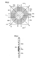
- Fig. 2 is a plan view showing the structure of power receiving unit 210
- Fig. 3 is a cross sectional view taken along a line III-III in Fig. 2 .
- Power receiving unit 210 in the present embodiment includes: a core unit 260 formed to have a shape of plate; a spiral coil 250 disposed at the power transmitting unit 410 side of core unit 260; a drawn wire 250a externally drawn from an outer end portion of spiral coil 250; and a drawn wire 250b externally drawn from an inner end portion of spiral coil 250.
- Core unit 260 has a shape of plate as a whole.
- core unit 260 a plurality of split cores are combined and are surrounded by insulating paper.
- ferrite is used for each of the split cores.
- core unit 260 of the present embodiment four ferrite cores 260a, 260b, 260c, 260d are used, and a groove g is provided between adjacent ones of ferrite cores 260a, 260b, 260c, 260d. It should be noted that one ferrite core may be used for core unit 260 and groove g may be provided in the surface thereof. Groove g is provided to coincide with the radial direction of spiral coil 250. In the present embodiment, center C of the groove having a shape of cross and center C of spiral coil 250 substantially coincide with each other.
- Drawn wire 250a externally drawn from the outer end portion of spiral coil 250 is directly connected to capacitor 220 externally provided.
- Drawn wire 250b externally drawn from the inner end portion of spiral coil 250 is routed through groove portion g and is externally drawn.
- the substantial thickness of power receiving unit 210 corresponds to only a total (W1) of the thickness of core unit 260 and the thickness of spiral coil 250 as shown in Fig. 3 , whereby the thickness of drawn wire 250b is not included in the substantial thickness of power receiving unit 210.
- the thickness of power receiving unit 210 can be suppressed from being increased, thereby suppressing increase in the thickness of power receiving device 200.
- groove portion g extends in the radial direction of spiral coil 250, so that drawn wire 250b also extends in the radial direction of spiral coil 250.
- magnetic fluxes from spiral coil 250 are emitted radially from center C as indicated by arrows M in Fig. 2 , so that the direction in which the magnetic fluxes are emitted and the direction in which drawn wire 250b is routed become substantially parallel to each other.
- an amount of the magnetic fluxes crossing drawn wire 250b can be reduced. Accordingly, generation of heat caused by the magnetic fluxes can be suppressed.
- Fig. 4 and Fig. 5 show a case where drawn wire 250b is routed over spiral coil 250.
- Drawn wire 250b passes over spiral coil 250, so that the substantial thickness of power receiving unit 210 corresponds to a thickness (W2) including not only the thickness of core unit 260 and the thickness of spiral coil 250 but also the thickness of drawn wire 250b, with the result that the thickness of power receiving unit 210 becomes thick.
- W2 thickness
- drawn wire 250b crosses the magnetic fluxes from spiral coil 250, thereby causing generation of heat by the magnetic fluxes.
- Fig. 6 is a plan view showing the structure of power transmitting unit 410
- Fig. 7 is a cross sectional view taken along a line VII-VII in Fig. 6 .
- Power transmitting unit 410 in the present embodiment includes: a core unit 460 formed to have a shape of plate; a spiral coil 450 disposed at the power receiving unit 210 side of core unit 460; a drawn wire 450a externally drawn from the outer end portion of spiral coil 450; and a drawn wire 450b externally drawn from the inner end portion of spiral coil 450.
- Core unit 460 has a shape of plate as a whole.
- core unit 460 a plurality of split cores are combined and are surrounded by insulating paper.
- ferrite is used for each of the split cores.
- core unit 460 of the present embodiment four ferrite cores 460a, 460b, 460c, 460d are used, and a groove g is provided between adjacent ones of ferrite cores 460a, 460b, 460c, 460d. It should be noted that one ferrite core may be used for core unit 460 and groove g may be provided in the surface thereof. Groove g is provided to coincide with the radial direction of spiral coil 450. In the present embodiment, center C of the groove having a shape of cross and center C of spiral coil 450 substantially coincide with each other.
- Drawn wire 450a externally drawn from the outer end portion of spiral coil 450 is directly connected to capacitor 420 externally provided.
- Drawn wire 450b externally drawn from the inner end portion of spiral coil 450 is routed through groove portion g and is externally drawn.
- the substantial thickness of power transmitting unit 410 corresponds to only a total (W1) of the thickness of core unit 460 and the thickness of spiral coil 450 as shown in Fig. 7 , whereby the thickness of drawn wire 450b is not included in the substantial thickness of power transmitting unit 410.
- the thickness of power transmitting unit 410 can be suppressed from being increased, thereby suppressing increase in the thickness of power transmitting device 400.
- groove portion g extends in the radial direction of spiral coil 450, so that drawn wire 450b also extends in the radial direction of spiral coil 450.
- magnetic fluxes from spiral coil 450 are emitted radially from center C as indicated by arrows M in Fig. 6 , so that the direction in which the magnetic fluxes are emitted and the direction in which drawn wire 450b is routed become substantially parallel to each other.
- an amount of the magnetic fluxes crossing drawn wire 450b can be reduced. Accordingly, generation of heat caused by the magnetic fluxes can be suppressed.
- a power receiving unit (210) of the present power receiving device includes: a core unit (260) formed to have a shape of plate; a spiral coil (250) disposed at the power transmitting unit (410) side of the core unit (260); and a drawn wire (250b) externally drawn from an inner end portion of the spiral coil (250), the core unit (260) having a groove portion (g) formed to extend in a radial direction of the spiral coil (250), the drawn wire (250b) being routed through the groove portion (g) and being drawn externally.
Landscapes
- Engineering & Computer Science (AREA)
- Power Engineering (AREA)
- Computer Networks & Wireless Communication (AREA)
- Current-Collector Devices For Electrically Propelled Vehicles (AREA)
- Electric Propulsion And Braking For Vehicles (AREA)
Abstract
Description
- This nonprovisional application is based on Japanese Patent Application No.
2014-014198 filed on January 29, 2014 - The present invention relates to a power receiving device that contactlessly receives electric power from a power transmitting device.
- As disclosed in Japanese Patent Laying-Open No.
2013-154815 2013-146154 2013-146148 2013-110822 2013-126327 2011-258807 2013-175734 2011-258807 2013-175734 - Such a spiral coil is formed by winding a coil wire such that the diameter thereof becomes larger as it extends from one end to the other end. The coil wire is externally drawn from an inner end portion, and the wire thus drawn passes over the upper surface of the coil. As a result, the power receiving device becomes thick in thickness.
- Furthermore, the drawn wire is disposed to transverse magnetic fluxes provided from the coil, with the result that heat may be generated due to magnetic fluxes crossing the drawn wire. The same problem arises also in a power transmitting device.
- The present invention has been made in view of the foregoing problem, and provides a power receiving device and a power transmitting device, both of which include configurations capable of suppressing increase in the thicknesses of the power receiving device and the power transmitting device.
- A power receiving device has a power receiving unit that contactlessly receives electric power from a power transmitting unit having a power transmitting coil when facing the power transmitting unit, the power receiving unit including a core unit formed to have a shape of plate, a spiral coil disposed at the power transmitting unit side of the core unit, and a drawn wire externally drawn from an inner end portion of the spiral coil, the core unit having a groove portion formed to extend in a radial direction of the spiral coil, the drawn wire being routed through the groove portion and being externally drawn.
- According to this configuration, since the drawn wire of the spiral coil is routed through the groove portion and is externally drawn, the substantial thickness of the power receiving unit corresponds to only a total of the thickness of the core unit and the thickness of the spiral coil, whereby the thickness of the drawn wire is not included in the substantial thickness of the power receiving unit. As a result, the thickness of the power receiving unit can be suppressed from being increased, thereby suppressing increase in the thickness of the power receiving device.
- Moreover, the groove portion is formed to extend in the radial direction of the spiral coil, so that the drawn wire routed through the groove portion does not transverse the magnetic fluxes provided from the coil. As a result, generation of heat caused by the magnetic fluxes can be suppressed.
- A power transmitting device has a power transmitting unit that contactlessly transmits electric power to a power receiving unit having a power receiving coil when facing the power receiving unit, the power transmitting unit including a core unit formed to have a shape of plate, a spiral coil disposed at the power receiving unit side of the core unit, and a drawn wire externally drawn from an inner end portion of the spiral coil, the core unit having a groove portion formed to extend in a radial direction of the spiral coil, the drawn wire being routed through the groove portion and being externally drawn.
- According to this configuration, since the drawn wire of the spiral coil is routed through the groove portion and is externally drawn, the substantial thickness of the power transmitting unit corresponds to only a total of the thickness of the core unit and the thickness of the spiral coil, whereby the thickness of the drawn wire is not included in the substantial thickness of the power transmitting unit. As a result, the thickness of the power transmitting unit can be suppressed from being increased, thereby suppressing increase in the thickness of the power transmitting device.
- Moreover, the groove portion is formed to extend in the radial direction of the spiral coil, so that the drawn wire routed through the groove portion does not transverse the magnetic fluxes provided from the coil. As a result, generation of heat caused by the magnetic fluxes can be suppressed.
- The foregoing and other objects, features, aspects and advantages of the present invention will become more apparent from the following detailed description of the present invention when taken in conjunction with the accompanying drawings.
-
-
Fig. 1 schematically shows a power transfer system of an embodiment. -
Fig. 2 is a plan view showing a structure of a power receiving unit of the embodiment. -
Fig. 3 is a cross sectional view taken along a line III-III inFig. 2 . -
Fig. 4 is a plan view showing a structure of a power receiving unit in a background art. -
Fig. 5 is a cross sectional view taken along a line V-V inFig. 4 . -
Fig. 6 is a plan view showing a structure of a power transmitting unit of the embodiment. -
Fig. 7 is a cross sectional view taken along a line VII-VII inFig. 6 . - The following describes an embodiment based on the present invention with reference to figures. When referring to the number, an amount, or the like in the description of the embodiment, the scope of the present invention is not necessarily limited to the number, the amount, or the like unless otherwise stated particularly. In the description of the embodiment, the same components and corresponding components are given the same reference characters and may not be described repeatedly.
- With reference to
Fig. 1 , apower transfer system 1000 in a first embodiment will be described.Fig. 1 schematically shows the entire configuration ofpower transfer system 1000.Power transfer system 1000 includes an electrically powered vehicle 100 (vehicle) and an externalpower feeding device 300. - With reference to
Fig. 1 , electrically poweredvehicle 100 includes a vehiclemain body 110 and apower receiving device 200. Provided in vehiclemain body 110 are a vehicle ECU 120 (control unit), arectifier 130, a DC/DC converter (hereinafter, simply referred to as "converter") 140, abattery 150, a power control unit (hereinafter, simply referred to as "PCU") 160, amotor unit 170, acommunication unit 180, and the like.Power receiving device 200 has apower receiving coil 250, and is disposed on the bottom surface of vehiclemain body 110. - External
power feeding device 300 includes apower transmitting device 400, and power transmittingdevice 400 has a power transmittingcoil 450. Whenpower receiving coil 250 ofpower receiving device 200 facespower transmitting coil 450 of power transmittingdevice 400,power receiving device 200 receives electric power contactlessly from power transmittingdevice 400.Power receiving device 200 has apower receiving unit 210, acapacitor 220 connected topower receiving unit 210, and a shield described below.Power receiving unit 210 has a solenoidtype core unit 260 andpower receiving coil 250. -
Power receiving coil 250 has a stray capacitance, and is connected to rectifier 130. An electric circuit is formed by a coefficient of induction ofpower receiving coil 250, the stray capacitance ofpower receiving coil 250, and the electric capacitance ofcapacitor 220. Capacitor 220 andpower receiving coil 250 are connected to each other in series, but they may be connected to each other in parallel. - In
power transfer system 1000, whenvehicle ECU 120 detects that a power feeding button is set to the ON state while vehiclemain body 110 is non-operational, the operation mode of the vehicle is switched to a charging mode. Viacommunication unit 180, vehicle ECU 120 instructs externalpower feeding device 300 to perform charging control forbattery 150. - External
power feeding device 300 includespower transmitting device 400, a high-frequency power device 310, and apower transmitting ECU 320 and acommunication unit 322. High-frequency power device 310 is connected to anAC power source 330. ACpower source 330 is a commercial power source, an independent power source device, or the like. Power transmittingdevice 400 is provided in a parking space, and is connected to high-frequency power device 310. Power transmitting ECU 320 controls driving of high-frequency power device 310 or the like. -
Communication unit 322 is a communication interface for performing wireless communication between externalpower feeding device 300 and electrically poweredvehicle 100. Fromcommunication unit 180 of electrically poweredvehicle 100,communication unit 322 receives battery information, a signal for instructing start, continuation, and stop of power transmission, and a signal for instructing increase or decrease of power to be transmitted, and outputs these pieces of information to power transmittingECU 320. -
Power transmitting device 400 has a power transmittingunit 410, acapacitor 420 connected topower transmitting unit 410, and a shield described below.Power transmitting unit 410 has a solenoid type core unit 440 andpower transmitting coil 450.Power transmitting coil 450 has a stray capacitance, and is connected to high-frequency power device 310. An electric circuit is formed by a coefficient of induction ofpower transmitting coil 450, a stray capacitance ofpower transmitting coil 450, and an electric capacity ofcapacitor 420.Capacitor 420 andpower transmitting coil 450 are connected to each other in series, but they may be connected to each other in parallel. - High-
frequency power device 310 receives electric power fromAC power source 330, converts it to high-frequency electric power, and supplies the converted high-frequency electric power to power transmittingcoil 450.Power transmitting coil 450 contactlessly transmits electric power to power receivingcoil 250 ofpower receiving unit 210 by means of electromagnetic induction. - Thus, in
power transmitting device 400, high-frequency power device 310 converts, into the high-frequency electric power, the electric power received fromAC power source 330, and supplies the converted high-frequency power to power transmittingcoil 450. Each ofpower transmitting unit 410 andpower receiving unit 210 includes the coil (450, 250) and the capacitor (420, 220), and is designed to resonate at a transmission frequency. It is preferable that a Q value indicating the resonance strength of each ofpower transmitting unit 410 andpower receiving unit 210 is equal to or higher than 100. - With reference to
Fig. 2 , the following describes a structure ofpower receiving unit 210.Fig. 2 is a plan view showing the structure ofpower receiving unit 210, andFig. 3 is a cross sectional view taken along a line III-III inFig. 2 . -
Power receiving unit 210 in the present embodiment includes: acore unit 260 formed to have a shape of plate; aspiral coil 250 disposed at thepower transmitting unit 410 side ofcore unit 260; a drawnwire 250a externally drawn from an outer end portion ofspiral coil 250; and a drawnwire 250b externally drawn from an inner end portion ofspiral coil 250. -
Core unit 260 has a shape of plate as a whole. Incore unit 260, a plurality of split cores are combined and are surrounded by insulating paper. For each of the split cores, ferrite is used. - For
core unit 260 of the present embodiment, fourferrite cores ferrite cores core unit 260 and groove g may be provided in the surface thereof. Groove g is provided to coincide with the radial direction ofspiral coil 250. In the present embodiment, center C of the groove having a shape of cross and center C ofspiral coil 250 substantially coincide with each other. -
Drawn wire 250a externally drawn from the outer end portion ofspiral coil 250 is directly connected tocapacitor 220 externally provided.Drawn wire 250b externally drawn from the inner end portion ofspiral coil 250 is routed through groove portion g and is externally drawn. - Since drawn
wire 250b ofspiral coil 250 is thus routed through groove portion g and is externally drawn, the substantial thickness ofpower receiving unit 210 corresponds to only a total (W1) of the thickness ofcore unit 260 and the thickness ofspiral coil 250 as shown inFig. 3 , whereby the thickness of drawnwire 250b is not included in the substantial thickness ofpower receiving unit 210. As a result, the thickness ofpower receiving unit 210 can be suppressed from being increased, thereby suppressing increase in the thickness ofpower receiving device 200. - Furthermore, groove portion g extends in the radial direction of
spiral coil 250, so that drawnwire 250b also extends in the radial direction ofspiral coil 250. When viewed in a plan view, magnetic fluxes fromspiral coil 250 are emitted radially from center C as indicated by arrows M inFig. 2 , so that the direction in which the magnetic fluxes are emitted and the direction in which drawnwire 250b is routed become substantially parallel to each other. As a result, an amount of the magnetic fluxes crossing drawnwire 250b can be reduced. Accordingly, generation of heat caused by the magnetic fluxes can be suppressed. -
Fig. 4 and Fig. 5 show a case where drawnwire 250b is routed overspiral coil 250.Drawn wire 250b passes overspiral coil 250, so that the substantial thickness ofpower receiving unit 210 corresponds to a thickness (W2) including not only the thickness ofcore unit 260 and the thickness ofspiral coil 250 but also the thickness of drawnwire 250b, with the result that the thickness ofpower receiving unit 210 becomes thick. - Moreover, drawn
wire 250b crosses the magnetic fluxes fromspiral coil 250, thereby causing generation of heat by the magnetic fluxes. - With reference to
Fig. 6 and Fig. 7 , the structure ofpower transmitting unit 410 will be described. It is possible to apply the structure ofpower receiving unit 210 shown inFig. 2 and Fig. 3 topower transmitting unit 410.Fig. 6 is a plan view showing the structure ofpower transmitting unit 410, andFig. 7 is a cross sectional view taken along a line VII-VII inFig. 6 . -
Power transmitting unit 410 in the present embodiment includes: acore unit 460 formed to have a shape of plate; aspiral coil 450 disposed at thepower receiving unit 210 side ofcore unit 460; a drawnwire 450a externally drawn from the outer end portion ofspiral coil 450; and a drawnwire 450b externally drawn from the inner end portion ofspiral coil 450. -
Core unit 460 has a shape of plate as a whole. Incore unit 460, a plurality of split cores are combined and are surrounded by insulating paper. For each of the split cores, ferrite is used. - For
core unit 460 of the present embodiment, fourferrite cores ferrite cores core unit 460 and groove g may be provided in the surface thereof. Groove g is provided to coincide with the radial direction ofspiral coil 450. In the present embodiment, center C of the groove having a shape of cross and center C ofspiral coil 450 substantially coincide with each other. -
Drawn wire 450a externally drawn from the outer end portion ofspiral coil 450 is directly connected tocapacitor 420 externally provided.Drawn wire 450b externally drawn from the inner end portion ofspiral coil 450 is routed through groove portion g and is externally drawn. - Since drawn
wire 450b ofspiral coil 450 is thus routed through groove portion g and is externally drawn, the substantial thickness ofpower transmitting unit 410 corresponds to only a total (W1) of the thickness ofcore unit 460 and the thickness ofspiral coil 450 as shown inFig. 7 , whereby the thickness of drawnwire 450b is not included in the substantial thickness ofpower transmitting unit 410. As a result, the thickness ofpower transmitting unit 410 can be suppressed from being increased, thereby suppressing increase in the thickness ofpower transmitting device 400. - Furthermore, groove portion g extends in the radial direction of
spiral coil 450, so that drawnwire 450b also extends in the radial direction ofspiral coil 450. When viewed in a plan view, magnetic fluxes fromspiral coil 450 are emitted radially from center C as indicated by arrows M inFig. 6 , so that the direction in which the magnetic fluxes are emitted and the direction in which drawnwire 450b is routed become substantially parallel to each other. As a result, an amount of the magnetic fluxes crossing drawnwire 450b can be reduced. Accordingly, generation of heat caused by the magnetic fluxes can be suppressed. - Although the present invention has been described and illustrated in detail, it is clearly understood that the same is by way of illustration and example only and is not to be taken by way of limitation, the scope of the present invention being interpreted by the terms of the appended claims.
- A power receiving unit (210) of the present power receiving device includes: a core unit (260) formed to have a shape of plate; a spiral coil (250) disposed at the power transmitting unit (410) side of the core unit (260); and a drawn wire (250b) externally drawn from an inner end portion of the spiral coil (250), the core unit (260) having a groove portion (g) formed to extend in a radial direction of the spiral coil (250), the drawn wire (250b) being routed through the groove portion (g) and being drawn externally.
Claims (8)
- A power receiving device (200) having a power receiving unit (210) that contactlessly receives electric power from a power transmitting unit (410) having a power transmitting coil (450) when facing said power transmitting unit (410),
said power receiving unit (210) including
a core unit (260) formed to have a shape of plate,
a spiral coil (250) disposed at the power transmitting unit (410) side of said core unit (260), and
a drawn wire (250b) externally drawn from an inner end portion of said spiral coil (250),
said core unit (260) having a groove portion (g) formed to extend in a radial direction of said spiral coil (250),
said drawn wire (250b) being routed through said groove portion (g) and being externally drawn. - The power receiving device according to claim 1, wherein said groove portion is a groove (g) having a shape of cross.
- The power receiving device according to claim 2, wherein a center of said groove (g) having the shape of cross and a center of said spiral coil (250) coincide with each other.
- The power receiving device according to claim 1, wherein
in said core unit (260), a plurality of split cores (260a, 260b, 260c, 260d) are combined, and
said groove (g) is provided between adjacent ones of said split cores (260a, 260b, 260c, 260d). - A power transmitting device having a power transmitting unit (410) that contactlessly transmits electric power to a power receiving unit (210) having a power receiving coil (250) when facing said power receiving unit (210),
said power transmitting unit (410) including
a core unit (460) formed to have a shape of plate,
a spiral coil (450) disposed at the power receiving unit (210) side of said core unit (460), and
a drawn wire (450b) externally drawn from an inner end portion of said spiral coil (450),
said core unit (460) having a groove portion (g) formed to extend in a radial direction of said spiral coil (450),
said drawn wire (450b) being routed through said groove portion (g) and being externally drawn. - The power transmitting device according to claim 5, wherein said groove portion is a groove (g) having a shape of cross.
- The power transmitting device according to claim 6, wherein a center of said groove (g) having the shape of cross and a center of said spiral coil (450) coincide with each other.
- The power transmitting device according to claim 5, wherein
in said core unit (460), a plurality of split cores (460a, 460b, 460c, 460d) are combined, and
said groove (g) is provided between adjacent ones of said split cores (460a, 460b, 460c, 460d).
Applications Claiming Priority (1)
| Application Number | Priority Date | Filing Date | Title |
|---|---|---|---|
| JP2014014198A JP2015142019A (en) | 2014-01-29 | 2014-01-29 | Power receiving device |
Publications (1)
| Publication Number | Publication Date |
|---|---|
| EP2911166A1 true EP2911166A1 (en) | 2015-08-26 |
Family
ID=52358704
Family Applications (1)
| Application Number | Title | Priority Date | Filing Date |
|---|---|---|---|
| EP15152280.2A Withdrawn EP2911166A1 (en) | 2014-01-29 | 2015-01-23 | Power receiving device and power transmitting device |
Country Status (4)
| Country | Link |
|---|---|
| US (1) | US20150213950A1 (en) |
| EP (1) | EP2911166A1 (en) |
| JP (1) | JP2015142019A (en) |
| CN (1) | CN104802657A (en) |
Cited By (1)
| Publication number | Priority date | Publication date | Assignee | Title |
|---|---|---|---|---|
| CN106856357A (en) * | 2015-12-09 | 2017-06-16 | 丰田自动车株式会社 | Current-collecting device and power transmission device |
Families Citing this family (5)
| Publication number | Priority date | Publication date | Assignee | Title |
|---|---|---|---|---|
| JP6160083B2 (en) * | 2013-01-08 | 2017-07-12 | 株式会社Ihi | Foreign object detection device |
| JP6743432B2 (en) | 2016-03-14 | 2020-08-19 | 株式会社Ihi | Coil device |
| JP6610583B2 (en) * | 2017-03-09 | 2019-11-27 | Tdk株式会社 | Wireless power transmission system |
| JP7330348B1 (en) * | 2022-07-01 | 2023-08-21 | 大日本印刷株式会社 | coil unit |
| JP2025026087A (en) * | 2023-08-10 | 2025-02-21 | 大日本印刷株式会社 | Coil unit, power transmitting device, power receiving device, power transmission system, and mobile body |
Citations (20)
| Publication number | Priority date | Publication date | Assignee | Title |
|---|---|---|---|---|
| GB2239424A (en) * | 1989-11-28 | 1991-07-03 | Mitsubishi Electric Corp | Non-contact type IC card |
| US20040119576A1 (en) * | 2001-02-14 | 2004-06-24 | Fumiaki Nakao | Noncontact coupler |
| EP1998342A2 (en) * | 2007-05-29 | 2008-12-03 | Sony Ericsson Mobile Communications Japan, Inc. | Coil module apparatus |
| US20100007215A1 (en) * | 2008-07-10 | 2010-01-14 | Nec Tokin Corporation | Soft magnetic sheet, module including the sheet and non-contact power transmission system including the module |
| US20110210617A1 (en) * | 2009-08-28 | 2011-09-01 | Pure Energy Solutions, Inc. | Power transmission across a substantially planar interface by magnetic induction and geometrically-complimentary magnetic field structures |
| JP2011258807A (en) | 2010-06-10 | 2011-12-22 | Showa Aircraft Ind Co Ltd | Non-contact power feeding device |
| US20120049991A1 (en) * | 2010-08-25 | 2012-03-01 | Access Business Group International Llc | Wireless power supply system and multi-layer shim assembly |
| JP2012191739A (en) * | 2011-03-10 | 2012-10-04 | Hitachi Metals Ltd | Transmission coil device, and power receiving device and power feeding device using the same |
| WO2012172813A1 (en) * | 2011-06-14 | 2012-12-20 | パナソニック株式会社 | Communication device |
| WO2013036146A1 (en) * | 2011-09-07 | 2013-03-14 | Auckland Uniservices Limited | Magnetic field shaping for inductive power transfer |
| WO2013035282A1 (en) * | 2011-09-08 | 2013-03-14 | パナソニック株式会社 | Non-contact charging module, electronic apparatus, and non-contact charging apparatus |
| WO2013035281A1 (en) * | 2011-09-09 | 2013-03-14 | パナソニック株式会社 | Non-contact charging module, electronic apparatus, and non-contact charging apparatus |
| JP2013110822A (en) | 2011-11-18 | 2013-06-06 | Toyota Motor Corp | Power transmission system, vehicle, and power supply facility |
| JP2013126327A (en) | 2011-12-15 | 2013-06-24 | Toyota Motor Corp | Power receiving apparatus, vehicle including the same, power transmission apparatus, and power transmission system |
| US20130181668A1 (en) * | 2010-12-01 | 2013-07-18 | Panasonic Corporation | Non-contact charging module and non-contact charging instrument |
| JP2013146148A (en) | 2012-01-16 | 2013-07-25 | Toyota Motor Corp | Vehicle |
| JP2013146154A (en) | 2012-01-16 | 2013-07-25 | Toyota Motor Corp | Power receiving device, power transmitting device, and power transmission system |
| JP2013154815A (en) | 2012-01-31 | 2013-08-15 | Toyota Motor Corp | Vehicle and power transmission system |
| US20130270921A1 (en) * | 2010-08-05 | 2013-10-17 | Auckland Uniservices Limited | Inductive power transfer apparatus |
| EP2669913A1 (en) * | 2011-03-09 | 2013-12-04 | Panasonic Corporation | Contactless charging module, contactless charging device, and method of manufacturing contactless charging module |
Family Cites Families (4)
| Publication number | Priority date | Publication date | Assignee | Title |
|---|---|---|---|---|
| JP2008198872A (en) * | 2007-02-14 | 2008-08-28 | Sumida Corporation | Magnetic element |
| JP4835786B1 (en) * | 2010-12-01 | 2011-12-14 | パナソニック株式会社 | Non-contact charging module and non-contact charging device |
| JP4835794B1 (en) * | 2011-01-26 | 2011-12-14 | パナソニック株式会社 | Receiving side non-contact charging module and receiving side non-contact charging device |
| JP4835801B1 (en) * | 2011-03-09 | 2011-12-14 | パナソニック株式会社 | Non-contact charging module and non-contact charging device |
-
2014
- 2014-01-29 JP JP2014014198A patent/JP2015142019A/en active Pending
-
2015
- 2015-01-16 US US14/598,501 patent/US20150213950A1/en not_active Abandoned
- 2015-01-23 EP EP15152280.2A patent/EP2911166A1/en not_active Withdrawn
- 2015-01-28 CN CN201510042016.3A patent/CN104802657A/en active Pending
Patent Citations (21)
| Publication number | Priority date | Publication date | Assignee | Title |
|---|---|---|---|---|
| GB2239424A (en) * | 1989-11-28 | 1991-07-03 | Mitsubishi Electric Corp | Non-contact type IC card |
| US20040119576A1 (en) * | 2001-02-14 | 2004-06-24 | Fumiaki Nakao | Noncontact coupler |
| EP1998342A2 (en) * | 2007-05-29 | 2008-12-03 | Sony Ericsson Mobile Communications Japan, Inc. | Coil module apparatus |
| US20100007215A1 (en) * | 2008-07-10 | 2010-01-14 | Nec Tokin Corporation | Soft magnetic sheet, module including the sheet and non-contact power transmission system including the module |
| US20110210617A1 (en) * | 2009-08-28 | 2011-09-01 | Pure Energy Solutions, Inc. | Power transmission across a substantially planar interface by magnetic induction and geometrically-complimentary magnetic field structures |
| JP2011258807A (en) | 2010-06-10 | 2011-12-22 | Showa Aircraft Ind Co Ltd | Non-contact power feeding device |
| US20130270921A1 (en) * | 2010-08-05 | 2013-10-17 | Auckland Uniservices Limited | Inductive power transfer apparatus |
| US20120049991A1 (en) * | 2010-08-25 | 2012-03-01 | Access Business Group International Llc | Wireless power supply system and multi-layer shim assembly |
| US20130181668A1 (en) * | 2010-12-01 | 2013-07-18 | Panasonic Corporation | Non-contact charging module and non-contact charging instrument |
| EP2669913A1 (en) * | 2011-03-09 | 2013-12-04 | Panasonic Corporation | Contactless charging module, contactless charging device, and method of manufacturing contactless charging module |
| JP2012191739A (en) * | 2011-03-10 | 2012-10-04 | Hitachi Metals Ltd | Transmission coil device, and power receiving device and power feeding device using the same |
| WO2012172813A1 (en) * | 2011-06-14 | 2012-12-20 | パナソニック株式会社 | Communication device |
| JP2013175734A (en) | 2011-06-14 | 2013-09-05 | Panasonic Corp | Communication device |
| WO2013036146A1 (en) * | 2011-09-07 | 2013-03-14 | Auckland Uniservices Limited | Magnetic field shaping for inductive power transfer |
| WO2013035282A1 (en) * | 2011-09-08 | 2013-03-14 | パナソニック株式会社 | Non-contact charging module, electronic apparatus, and non-contact charging apparatus |
| WO2013035281A1 (en) * | 2011-09-09 | 2013-03-14 | パナソニック株式会社 | Non-contact charging module, electronic apparatus, and non-contact charging apparatus |
| JP2013110822A (en) | 2011-11-18 | 2013-06-06 | Toyota Motor Corp | Power transmission system, vehicle, and power supply facility |
| JP2013126327A (en) | 2011-12-15 | 2013-06-24 | Toyota Motor Corp | Power receiving apparatus, vehicle including the same, power transmission apparatus, and power transmission system |
| JP2013146148A (en) | 2012-01-16 | 2013-07-25 | Toyota Motor Corp | Vehicle |
| JP2013146154A (en) | 2012-01-16 | 2013-07-25 | Toyota Motor Corp | Power receiving device, power transmitting device, and power transmission system |
| JP2013154815A (en) | 2012-01-31 | 2013-08-15 | Toyota Motor Corp | Vehicle and power transmission system |
Cited By (4)
| Publication number | Priority date | Publication date | Assignee | Title |
|---|---|---|---|---|
| CN106856357A (en) * | 2015-12-09 | 2017-06-16 | 丰田自动车株式会社 | Current-collecting device and power transmission device |
| EP3179493A3 (en) * | 2015-12-09 | 2017-06-28 | Toyota Jidosha Kabushiki Kaisha | Electric power receiving device and electric power transmission device |
| RU2650881C1 (en) * | 2015-12-09 | 2018-04-18 | Тойота Дзидося Кабусики Кайся | Electric energy reception device and electric energy transmission device |
| CN106856357B (en) * | 2015-12-09 | 2019-12-31 | 丰田自动车株式会社 | Power receiving device and power transmitting device |
Also Published As
| Publication number | Publication date |
|---|---|
| CN104802657A (en) | 2015-07-29 |
| US20150213950A1 (en) | 2015-07-30 |
| JP2015142019A (en) | 2015-08-03 |
Similar Documents
| Publication | Publication Date | Title |
|---|---|---|
| EP2911166A1 (en) | Power receiving device and power transmitting device | |
| JP6384991B2 (en) | Power transmission device and wireless power transmission system | |
| CN102870315B (en) | Power receiving system and power reception method | |
| US9533592B2 (en) | Vehicle | |
| EP2571134A1 (en) | Resonance-type non-contact power supply system | |
| US10279691B2 (en) | Contactless feeding pad and contactless feeding device | |
| US8948275B2 (en) | Power line communication system for vehicle | |
| JP2010239777A (en) | Wireless power device and wireless power receiving method | |
| WO2018222429A1 (en) | Transmitting assembly for a universal wireless charging device and a method thereof | |
| US20170126059A1 (en) | Contactless power supply system supplying power using power supply pad in contact less manner | |
| JP2012060812A (en) | Non-contact power transmission device | |
| US20200144870A1 (en) | Multi-mode wireless charging system | |
| JP2021093883A (en) | Non-contact power supply system | |
| EP3217514B1 (en) | Coil device, wireless power transfer system, and auxiliary magnetic member | |
| CN111667995B (en) | Coil unit, wireless power supply device, wireless power receiving device and wireless power transmission system | |
| JP6164490B2 (en) | Non-contact power feeding device | |
| JP6040510B2 (en) | Power transmission system | |
| JP2016018802A (en) | Coil unit | |
| JP6085817B2 (en) | Power transmission system | |
| JP6394123B2 (en) | Coil unit | |
| JP2015115580A (en) | Power transmission system | |
| JP2015156780A (en) | power transmission system | |
| JP6164491B2 (en) | Non-contact power feeding device | |
| JP2015084366A (en) | Power receiving device | |
| JP2015115579A (en) | Power transmission system |
Legal Events
| Date | Code | Title | Description |
|---|---|---|---|
| PUAI | Public reference made under article 153(3) epc to a published international application that has entered the european phase |
Free format text: ORIGINAL CODE: 0009012 |
|
| 17P | Request for examination filed |
Effective date: 20150123 |
|
| AK | Designated contracting states |
Kind code of ref document: A1 Designated state(s): AL AT BE BG CH CY CZ DE DK EE ES FI FR GB GR HR HU IE IS IT LI LT LU LV MC MK MT NL NO PL PT RO RS SE SI SK SM TR |
|
| AX | Request for extension of the european patent |
Extension state: BA ME |
|
| RIN1 | Information on inventor provided before grant (corrected) |
Inventor name: YUASA, HIROAKI |
|
| GRAP | Despatch of communication of intention to grant a patent |
Free format text: ORIGINAL CODE: EPIDOSNIGR1 |
|
| INTG | Intention to grant announced |
Effective date: 20160720 |
|
| STAA | Information on the status of an ep patent application or granted ep patent |
Free format text: STATUS: THE APPLICATION IS DEEMED TO BE WITHDRAWN |
|
| 18D | Application deemed to be withdrawn |
Effective date: 20161201 |