EP2910813A2 - Damping system with energy recovery for a motor vehicle and drive device using such a damping system - Google Patents
Damping system with energy recovery for a motor vehicle and drive device using such a damping system Download PDFInfo
- Publication number
- EP2910813A2 EP2910813A2 EP14004206.0A EP14004206A EP2910813A2 EP 2910813 A2 EP2910813 A2 EP 2910813A2 EP 14004206 A EP14004206 A EP 14004206A EP 2910813 A2 EP2910813 A2 EP 2910813A2
- Authority
- EP
- European Patent Office
- Prior art keywords
- shaft
- rotor
- damper
- damping system
- pendulum
- Prior art date
- Legal status (The legal status is an assumption and is not a legal conclusion. Google has not performed a legal analysis and makes no representation as to the accuracy of the status listed.)
- Granted
Links
- 238000013016 damping Methods 0.000 title claims abstract description 87
- 238000011084 recovery Methods 0.000 title claims abstract description 9
- 230000033001 locomotion Effects 0.000 claims abstract description 34
- 230000008878 coupling Effects 0.000 claims description 14
- 238000010168 coupling process Methods 0.000 claims description 14
- 238000005859 coupling reaction Methods 0.000 claims description 14
- 238000002485 combustion reaction Methods 0.000 claims description 13
- 230000005284 excitation Effects 0.000 claims description 12
- 238000001514 detection method Methods 0.000 claims description 7
- 230000000694 effects Effects 0.000 claims description 6
- 230000006698 induction Effects 0.000 claims description 4
- 230000003993 interaction Effects 0.000 claims description 3
- 230000010355 oscillation Effects 0.000 abstract description 4
- 229920001971 elastomer Polymers 0.000 description 5
- 239000000806 elastomer Substances 0.000 description 5
- 239000012530 fluid Substances 0.000 description 5
- 230000004913 activation Effects 0.000 description 4
- 230000001939 inductive effect Effects 0.000 description 3
- 230000009467 reduction Effects 0.000 description 3
- 230000001172 regenerating effect Effects 0.000 description 3
- 239000006096 absorbing agent Substances 0.000 description 2
- 230000001419 dependent effect Effects 0.000 description 2
- 238000011161 development Methods 0.000 description 2
- 230000018109 developmental process Effects 0.000 description 2
- 230000001965 increasing effect Effects 0.000 description 2
- 239000002918 waste heat Substances 0.000 description 2
- 230000003044 adaptive effect Effects 0.000 description 1
- 230000002238 attenuated effect Effects 0.000 description 1
- 238000006243 chemical reaction Methods 0.000 description 1
- 238000011217 control strategy Methods 0.000 description 1
- 238000010304 firing Methods 0.000 description 1
- 230000004048 modification Effects 0.000 description 1
- 238000012986 modification Methods 0.000 description 1
- 230000000638 stimulation Effects 0.000 description 1
Images

Classifications
-
- F—MECHANICAL ENGINEERING; LIGHTING; HEATING; WEAPONS; BLASTING
- F16—ENGINEERING ELEMENTS AND UNITS; GENERAL MEASURES FOR PRODUCING AND MAINTAINING EFFECTIVE FUNCTIONING OF MACHINES OR INSTALLATIONS; THERMAL INSULATION IN GENERAL
- F16F—SPRINGS; SHOCK-ABSORBERS; MEANS FOR DAMPING VIBRATION
- F16F15/00—Suppression of vibrations in systems; Means or arrangements for avoiding or reducing out-of-balance forces, e.g. due to motion
- F16F15/10—Suppression of vibrations in rotating systems by making use of members moving with the system
- F16F15/18—Suppression of vibrations in rotating systems by making use of members moving with the system using electric, magnetic or electromagnetic means
-
- F—MECHANICAL ENGINEERING; LIGHTING; HEATING; WEAPONS; BLASTING
- F16—ENGINEERING ELEMENTS AND UNITS; GENERAL MEASURES FOR PRODUCING AND MAINTAINING EFFECTIVE FUNCTIONING OF MACHINES OR INSTALLATIONS; THERMAL INSULATION IN GENERAL
- F16F—SPRINGS; SHOCK-ABSORBERS; MEANS FOR DAMPING VIBRATION
- F16F15/00—Suppression of vibrations in systems; Means or arrangements for avoiding or reducing out-of-balance forces, e.g. due to motion
- F16F15/10—Suppression of vibrations in rotating systems by making use of members moving with the system
- F16F15/14—Suppression of vibrations in rotating systems by making use of members moving with the system using masses freely rotating with the system, i.e. uninvolved in transmitting driveline torque, e.g. rotative dynamic dampers
- F16F15/1485—Suppression of vibrations in rotating systems by making use of members moving with the system using masses freely rotating with the system, i.e. uninvolved in transmitting driveline torque, e.g. rotative dynamic dampers the rotation being unlimited with respect to driving means
-
- F—MECHANICAL ENGINEERING; LIGHTING; HEATING; WEAPONS; BLASTING
- F16—ENGINEERING ELEMENTS AND UNITS; GENERAL MEASURES FOR PRODUCING AND MAINTAINING EFFECTIVE FUNCTIONING OF MACHINES OR INSTALLATIONS; THERMAL INSULATION IN GENERAL
- F16F—SPRINGS; SHOCK-ABSORBERS; MEANS FOR DAMPING VIBRATION
- F16F15/00—Suppression of vibrations in systems; Means or arrangements for avoiding or reducing out-of-balance forces, e.g. due to motion
- F16F15/30—Flywheels
Landscapes
- Engineering & Computer Science (AREA)
- General Engineering & Computer Science (AREA)
- Physics & Mathematics (AREA)
- Acoustics & Sound (AREA)
- Aviation & Aerospace Engineering (AREA)
- Mechanical Engineering (AREA)
- Electromagnetism (AREA)
- Vibration Prevention Devices (AREA)
- Arrangement Or Mounting Of Propulsion Units For Vehicles (AREA)
Abstract
Die Erfindung betrifft ein Dämpfungssystem, vorzugsweise für ein Fahrzeug, zur Schwingungsdämpfung, vorzugsweise Torsionsschwingungsdämpfung, und zur Energierückgewinnung aus der Schwingungsdämpfung. Das Dämpfungssystem umfasst einen Dämpfer (D) und eine Welle (1), wobei der Dämpfer (D) zumindest einen mittels der Welle (1) drehbaren Läufer (4.1-4.3) zum Zusammenwirken mit zumindest einem mittels der Welle (1) drehbaren Dämpfer-Läufer (3.1-3.3) umfasst, wobei der zumindest eine Läufer (4.1-4.3) pendelbar ausgeführt ist, so dass mittels einer Relativbewegung zwischen dem zumindest einen Läufer (4.1-4.3) und dem zumindest einen Dämpfer-Läufer (3.1-3.3) die Schwingung der Welle (1) dämpfbar und Energie zurückgewinnbar ist. Ferner betrifft die Erfindung eine Antriebsvorrichtung mit einem derartigen Dämpfungssystem.The invention relates to a damping system, preferably for a vehicle, for vibration damping, preferably torsional vibration damping, and energy recovery from the vibration damping. The damping system comprises a damper (D) and a shaft (1), wherein the damper (D) at least one by means of the shaft (1) rotatable rotor (4.1-4.3) for cooperation with at least one by means of the shaft (1) rotatable damper Runner (3.1-3.3) comprises, wherein the at least one rotor (4.1-4.3) is designed to be pendulum, so that by means of a relative movement between the at least one rotor (4.1-4.3) and the at least one damper rotor (3.1-3.3) Oscillation of the shaft (1) can be damped and energy can be recovered. Furthermore, the invention relates to a drive device with such a damping system.
Description
Die Erfindung betrifft ein Dämpfungssystem zur Schwingungsdämpfung und zur Energierückgewinnung aus der Schwingungsdämpfung, zweckmäßig für ein Kraftfahrzeug und eine Antriebsvorrichtung mit einem derartigen Dämpfungssystem.The invention relates to a damping system for vibration damping and energy recovery from the vibration damping, suitable for a motor vehicle and a drive device with such a damping system.
Stand der Technik ist, dass die Verringerung von Torsionsschwingungen von Fahrzeugwellen durch Dämpfer und/oder Tilger geschieht, die die Schwingungsenergie in Wärme umsetzen, die als Abwärme ungenutzt in die Umgebung abgegeben wird. Zum allgemeinen Stand der Technik kann z. B. auf die
Eine Aufgabe der Erfindung ist es, die Energieeffizienz eines Kraftfahrzeugs zu verbessern.An object of the invention is to improve the energy efficiency of a motor vehicle.
Diese Aufgabe kann mit den Merkmalen des Anspruchs 1 gelöst werden. Vorteilhafte Weiterbildungen der Erfindung können den Unteransprüchen und der folgenden Beschreibung entnommen werden.This object can be achieved with the features of
Die Erfindung schafft ein Dämpfungssystem, vorzugsweise für ein Kraftfahrzeug, zur Schwingungsdämpfung, zweckmäßig Torsionsschwingungsdämpfung, und zur Rückgewinnung von Energie, vorzugsweise in elektrischer Form, aus der Schwingungsdämpfung, insbesondere mittels Umwandlung von mechanischer Energie in elektrische Energie.The invention provides a damping system, preferably for a motor vehicle, for vibration damping, suitable torsional vibration damping, and for the recovery of energy, preferably in electrical form, from the vibration damping, in particular by converting mechanical energy into electrical energy.
Das Dämpfungssystem umfasst eine Welle, die im Betrieb Schwingungen aufweist. Das Dämpfungssystem umfasst einen Dämpfer, wobei der Dämpfer zumindest einen mittels der Welle drehbaren Läufer und zumindest einen mittels der Welle drehbaren Dämpfer-Läufer umfasst. Der zumindest eine Läufer und der zumindest eine Dämpfer-Läufer sind zum vorzugsweise induktiven Zusammenwirken ausgeführt.The damping system comprises a shaft which has vibrations during operation. The damping system comprises a damper, wherein the damper at least one rotatable by means of the shaft rotor and at least one rotatable by means of the shaft Damper rotor includes. The at least one rotor and the at least one damper rotor are designed for preferably inductive interaction.
Der zumindest eine Läufer ist pendelbar ausgeführt, um zweckmäßig als Pendel zu wirken und/oder die Pendelbewegung der Drehbewegung der Welle zu überlagern, so dass mittels einer Relativbewegung (z. B. einer Verdreh- oder Verschwenkung, zweckmäßig größer 0°) zwischen dem pendelbaren Läufer und dem Dämpfer-Läufer die Schwingung der Welle gedämpft und Energie vorzugsweise mittels Induktion und/oder in elektrischer Form zurückgewonnen werden kann. Die Relativbewegung findet zweckmäßig innerhalb eines Magnetfelds statt.The at least one rotor is designed to be pendulum in order to function as a pendulum and / or to superimpose the pendulum motion of the rotational movement of the shaft, so that by means of a relative movement (eg a twisting or pivoting, advantageously greater than 0 °) between the pendulum Runner and the damper rotor damped the vibration of the shaft and energy preferably by induction and / or in electrical form can be recovered. The relative movement expediently takes place within a magnetic field.
Das Dämpfungssystem kann zweckmäßig die Amplituden der Schwingungen der Welle dadurch verringern, dass die entzogene Schwingungsenergie als zusätzliche Antriebs- oder Nutzenergie zurückgeführt werden kann.The damping system can expediently reduce the amplitudes of the oscillations of the shaft by virtue of the fact that the extracted oscillation energy can be returned as additional drive or useful energy.
Die Schwingungsenergie kann vorzugsweise dem kritischen Bereich der Welle entzogen und dem kraftabgebenden Bereich als Nutz- oder Antriebsenergie zurückgeführt werden.The vibration energy can preferably be removed from the critical region of the shaft and returned to the force-emitting region as useful or driving energy.
Auch auf der kraftabgebenden Seite können schädigende Frequenzanteile der Schwingung der Welle entzogen und in einem unschädlichen Frequenzbereich als Nutz- oder Antriebsenergie zurückgeführt werden.Damaging frequency components can also be removed from the oscillation of the shaft on the force-emitting side and returned as useful or driving energy in a harmless frequency range.
Die Energie kann stetig oder temporär zurückgeführt werden. Dabei ist es z. B. möglich, zumindest einen Teil der zurückgewonnenen Energie zwischenzuspeichern.The energy can be returned steadily or temporarily. It is z. B. possible to buffer at least a portion of the recovered energy.
Das Dämpfungssystem kann derart steuerbar ausgeführt werden, dass in quasi jedem Betriebspunkt eine maximale Dämpfung erreicht wird, was in der Folge zu einem Maximum an zurückgewonnener Antriebs- oder Nutzenergie führt.The damping system can be designed to be controllable so that maximum damping is achieved in virtually every operating point, resulting in the result in a maximum of recovered drive or useful energy.
Zweckmäßig können der dämpfende und/oder energiegewinnende Teil und der einspeisende Teil des Dämpfungssystems ineinander integriert sein.Suitably, the damping and / or energy-generating part and the feeding part of the damping system can be integrated with each other.
Die zurückgewonnene Energie kann auch anderen Aggregaten des Kraftfahrzeugs zumindest teilweise zurückgeführt werden.The recovered energy can also be at least partially attributed to other units of the motor vehicle.
Es ist möglich, dass der zumindest eine pendelbare Läufer und der zumindest eine Dämpfer-Läufer unterschiedlich steif an die Drehbewegung der Welle gekoppelt sind. Daraus folgt, dass sich die Drehbewegung der Welle unterschiedlich auf die Drehbewegung des pendelbaren Läufers und die Drehbewegung des Dämpfer-Läufers auswirkt.It is possible that the at least one pendulous rotor and the at least one damper rotor are coupled differently rigidly to the rotational movement of the shaft. It follows that the rotational movement of the shaft has different effects on the rotational movement of the pendulum runner and the rotational movement of the damper rotor.
Der zumindest eine Dämpfer-Läufer ist vorzugsweise starr an die Drehbewegung der Welle gekoppelt, so dass zweckmäßig die Drehbewegung der Welle zumindest nahezu der Drehbewegung des Dämpfer-Läufers entspricht.The at least one damper rotor is preferably rigidly coupled to the rotational movement of the shaft, so that suitably corresponds to the rotational movement of the shaft at least almost the rotational movement of the damper rotor.
Der zumindest eine Dämpfer-Läufer und der zumindest eine pendelbare Läufer bilden vorzugsweise eine Stator-Rotor-Kombination, mit zumindest einem an die Drehbewegung der Welle starr gekoppeltem Dämpfer-Läufer und zumindest einem nichtstarr und/oder pendelbar an die Drehbewegung der Welle gekoppeltem Läufer.The at least one damper rotor and the at least one pendulous rotor preferably form a stator-rotor combination with at least one damper rotor rigidly coupled to the rotary motion of the shaft and at least one rotor non-rigid and / or pendulum-coupled to the rotary motion of the shaft.
Der zumindest eine pendelbare Läufer kann eine Spule oder einen Magneten, zweckmäßig einen Permanentmagneten, umfassen. Der zumindest eine Dämpfer-Läufer kann ebenfalls eine Spule oder einen Magneten, zweckmäßig einen Permanentmagneten, umfassen. Der zumindest eine pendelbare Läufer und/oder der zumindest eine Dämpfer-Läufer stellen somit zweckmäßig einen als Generatorläufer ausgeführten Rotor dar.The at least one pendulous rotor may comprise a coil or a magnet, suitably a permanent magnet. The at least one damper rotor may also comprise a coil or a magnet, suitably a permanent magnet. The at least one pendulum runner and / or the at least one damper rotor thus expediently represent a rotor designed as a generator rotor.
Es ist möglich, dass zumindest ein Läufer mittels einer Pendellagerung gelagert ist und/oder zumindest abschnittsweise elastisch ausgeführt ist. Mittels geeigneter Elastizität können z. B. relativ weiche oder z. B. relativ steife Läufer ausgebildet werden.It is possible that at least one runner is mounted by means of a pendulum bearing and / or at least partially elastic. By means of suitable elasticity z. B. relatively soft or z. B. relatively stiff rotor can be formed.
Die Pendellagerung kann vorzugsweise als zumindest eines von Folgenden ausgeführt sein: Drehlagerung, Federlagerung, Elastomerlagerung, Hydrauliklagerung und/oder Piezo-Effekt nutzende Lagerung.The self-aligning bearing can preferably be embodied as at least one of the following: pivot bearing, spring bearing, elastomer bearing, hydraulic bearing and / or bearing utilizing piezo effect.
Der zumindest eine pendelbare Läufer umfasst vorzugsweise einen sich relativ zur Welle radial nach außen erstreckenden Drehpendelarm.The at least one pendulous rotor preferably comprises a rotary pendulum arm extending radially outward relative to the shaft.
Der zumindest eine Läufer kann, vorzugsweise mittels der Pendellagerung, mit der Welle oder einem an die Drehbewegung der Welle gekoppelten Kopplungsteil verbunden sein. Die Pendellagerung kann quasi direkt an der Welle oder dem Kopplungsteil gelagert sein oder in Radialrichtung der Welle vom Außenumfang der Welle beabstandet sein oder in Radialrichtung des Kopplungsteils vom Außenumfang des Kopplungsteils beabstandet sein.The at least one rotor can be connected, preferably by means of the pendulum bearing, to the shaft or to a coupling part coupled to the rotational movement of the shaft. The pendulum bearing can be stored virtually directly on the shaft or the coupling part or spaced in the radial direction of the shaft from the outer circumference of the shaft or be spaced in the radial direction of the coupling part of the outer periphery of the coupling part.
Vorzugsweise sind zumindest zwei Läufer und/oder zumindest zwei Dämpfer-Läufer in Längsrichtung der Welle hintereinander und vorzugsweise separiert voneinander angeordnet. Alternativ oder ergänzend können zumindest zwei Läufer aneinandergekoppelt sein und zweckmäßig über ein und dieselbe Pendellagerung an die Drehbewegung der Welle gekoppelt sein.Preferably, at least two runners and / or at least two damper runners are arranged one behind the other in the longitudinal direction of the shaft and preferably separated from one another. Alternatively or additionally, at least two runners can be coupled to one another and expediently coupled to the rotary movement of the shaft via one and the same pendulum bearing.
Es ist möglich, dass zumindest zwei Läufer, vorzugsweise inklusive der Pendellagerungen, identisch ausgeführt sind und/oder zumindest zwei Läufer sich durch zumindest eines von Folgenden voneinander unterscheiden: Sie sind unterschiedlich steif pendelbar gelagert, sie weisen eine unterschiedliche Pendelmasse (Massenträgheitsmoment) auf, sie weisen eine unterschiedliche Länge auf, sie weisen eine unterschiedliche Elastizität auf, und/oder sie weisen in deren Längsrichtung unterschiedlich große Luftdistanzen zu den Dämpfer-Läufern auf.It is possible for at least two runners, preferably including the self-aligning bearings, to be designed identically and / or for at least two runners to differ from each other by at least one of the following: they are mounted with different stiffness, they have a different pendulum mass (mass moment of inertia) have a different length, they have a different elasticity, and / or they have in the longitudinal direction of different sized air distances to the damper-runners on.
Der zumindest eine Läufer und/oder der zumindest eine Dämpfer-Läufer sind zweckmäßig mit einem Elektroterminal versehen, um ein Magnetfeld zu erzeugen. Das Elektroterminal des zumindest einen Läufers kann alternativ oder ergänzend dazu genutzt werden, um ein Überschwingen oder eine Pendelanregung des zumindest einen Läufers zur Krafteinleitung in die Welle zu erzeugen.The at least one runner and / or the at least one damper runner are expediently provided with an electrical terminal in order to generate a magnetic field. The electroterminal of the at least one rotor can alternatively or additionally be used to generate an overshoot or a pendulum excitation of the at least one rotor for introducing force into the shaft.
Vorzugsweise verfügen zumindest zwei Läufer und/oder zumindest zwei Dämpfer-Läufer über eigene, separate Elektroterminals, um örtlich unterschiedliche Magnetfelder zu erzeugen.Preferably, at least two runners and / or at least two damper runners have their own separate electrical terminals in order to generate locally different magnetic fields.
Das Dämpfungssystem umfasst vorzugsweise ein Dämpfer-Gehäuse, das drehfest, insbesondere starr, mit der Welle verbunden ist, den zumindest einen Dämpfer-Läufer trägt und den zumindest einen Läufer trägt und zugleich in seinem Innenraum aufnimmt. Alternativ oder ergänzend kann der Dämpfer-Läufer an oder in einer Wand des Dämpfer-Gehäuses angeordnet sein.The damping system preferably comprises a damper housing which is non-rotatably, in particular rigidly, connected to the shaft which carries at least one damper rotor and which carries at least one rotor and at the same time accommodates it in its interior. Alternatively or additionally, the damper rotor can be arranged on or in a wall of the damper housing.
Das Dämpfer-Gehäuse kann vorzugsweise an einem Ende der Welle angeordnet sein.The damper housing may preferably be arranged at one end of the shaft.
Es ist möglich, dass zumindest ein pendelbarer Läufer mittels einer Starrlagerung gelagert ist, allerdings wie schon zuvor erwähnt elastisch ausgeführt ist, um trotzdem als Pendel zu wirken.It is possible that at least one pendulum runner is mounted by means of a rigid bearing, however, as already mentioned, is designed to be elastic, in order nevertheless to act as a pendulum.
Es ist möglich, dass zumindest zwei Läufer relativ zueinander pendelbar und/oder verdrehbar sind und folglich quasi phasenversetzt und/oder mit unterschiedlicher Frequenz schwingen können.It is possible for at least two runners to be able to be displaced and / or rotated relative to one another, and consequently to oscillate in phase out of phase and / or at different frequencies.
Das Dämpfungssystem kann ferner eine Steuereinrichtung aufweisen, mittels der ein Erregerstrom und/oder eine Erregerspannung auf den zumindest einen Läufer und/oder den zumindest einen Dämpfer-Läufer so steuerbar ist, insbesondere erhöhbar oder maximierbar ist, dass eine zweckmäßig maximale Induktion und folglich eine zweckmäßig maximale Schwingungsdämpfung erzielbar ist.The damping system may further comprise a control device, by means of which an exciter current and / or an excitation voltage on the at least one rotor and / or the at least one damper rotor is controllable, in particular can be increased or maximized, that a suitably maximum induction and consequently a functional maximum vibration damping can be achieved.
Das Dämpfungssystem kann eine Erfassungseinrichtung zum Erfassen von Drehungleichförmigkeiten (zum Beispiel Schwingungen) der Welle und/oder eines Wellen-Antriebsmotors umfassen, wobei die Steuereinrichtung den Erregerstrom, die Erregerspannung und/oder die Energie-Rückführung in Abhängigkeit der mittels der Erfassungseinrichtung erfassten Drehungleichförmigkeiten steuern kann.The damping system may comprise a detection device for detecting rotational nonuniformities (for example vibrations) of the shaft and / or a shaft drive motor, wherein the control device may control the excitation current, the excitation voltage and / or the energy feedback in dependence on the rotational irregularities detected by the detection device ,
Die zurückgewonnene Energie kann in einem Akkumulator zwischengespeichert werden und/oder einem Fahrzeug-Aggregat als Antrieb- oder Nutzenergie zur Verfügung gestellt werden.The recovered energy can be cached in an accumulator and / or provided to a vehicle aggregate as drive or useful energy.
Die mittels des Dämpfungssystems zurückgewonnene Energie kann an die antreibende Seite der Welle zurückgeführt werden, z. B. stetig oder temporär.The energy recovered by the damping system can be returned to the driving side of the shaft, e.g. B. steady or temporary.
Die Steuereinrichtung kann die Rückführung der zurückgewonnenen Energie so steuern, zum Beispiel phasenversetzt und/oder moduliert, dass auf der abtreibenden Seite der Welle ein Minimum an Drehschwingungen entsteht.The controller may control the feedback of the recovered energy, for example out of phase and / or modulated, to produce a minimum of torsional vibration on the driven side of the shaft.
Das Merkmal "Steuern" ist im Rahmen der Erfindung breit auszulegen und kann zweckgemäß auch ein "Regeln" umfassen.The term "control" is to be interpreted broadly in the context of the invention and may suitably also include a "rules".
Zu erwähnen ist, dass z. B. ein elektromotorisch wirkender Aktuator zur Energierückspeisung verwendet werden kann, der optional so steuerbar ist, dass sich auf der kraftabgebenden Seite ein dämpfender und/oder tilgender Effekt einstellt.It should be mentioned that z. B. an electric motor acting actuator for energy recovery can be used, which is optionally controllable so that adjusts a damping and / or eradicating effect on the force-emitting side.
Zu erwähnen ist ferner, dass die Erfindung vorzugsweise Ausführungsformen mit mehreren pendelbaren Läufern und mehreren Dämpfer-Läufern umfasst.It should also be mentioned that the invention preferably comprises embodiments with a plurality of pendulum runners and a plurality of damper runners.
Zu erwähnen ist außerdem, dass die Pendelbewegung des zumindest einen pendelbaren Läufers der Drehbewegung der Welle überlagerbar ist und dadurch insbesondere die Relativbewegung zwischen dem zumindest einen Läufer und dem zumindest einem Dämpfer-Läufer ermöglichbar ist.It should also be mentioned that the pendulum movement of the at least one pendulous rotor of the rotational movement of the shaft is superimposed and thereby in particular the relative movement between the at least one rotor and the at least one damper rotor is possible.
Zu erwähnen ist des Weiteren, dass der zumindest eine Läufer und/der der zumindest eine Dämpfer-Läufer vorzugsweise mittelbar mit der Welle verbunden sind, z. B. über das Dämpfer-Gehäuse oder ein anderes Verbindungselement. Es sind allerdings auch Ausführungsformen mit direkter Verbindung möglich.It should also be mentioned that the at least one rotor and / or the at least one damper rotor are preferably connected indirectly with the shaft, z. B. via the damper housing or other connection element. However, embodiments with direct connection are also possible.
Die Aufgabe der Erfindung kann ferner gelöst werden durch die Merkmale des Anspruchs 15.The object of the invention can be further solved by the features of claim 15.
Demnach umfasst die erfindungsgemäße Antriebsvorrichtung, vorzugsweise für ein Fahrzeug, einen als Brennkraftmaschine ausgebildeten Wellenantriebsmotor mit einer als Kurbelwelle ausgebildeten Welle, ein auf der kraftabgebenden Seite der Brennkraftmaschine im Bereich eines axialen Endes der Brennkraftmaschine angeordnetes Schwungrad und ein vorstehend beschriebenes Dämpfungssystem. Dabei ist der Dämpfer des Dämpfungssystems im Bereich eines dem Schwungrad gegenüberliegenden axialen Endes der Kurbelwelle angeordnet.Accordingly, the drive device according to the invention, preferably for a vehicle, designed as an internal combustion engine shaft drive motor with a crankshaft designed as a shaft, arranged on the force-emitting side of the internal combustion engine in the region of an axial end of the internal combustion engine flywheel and a damping system described above. In this case, the damper of the damping system is arranged in the region of the flywheel opposite axial end of the crankshaft.
Durch die Anordnung des Dämpfers eines derartigen Dämpfungssystems im Bereich des dem Schwungrad gegenüberliegenden axialen Endes der Kurbelwelle können insbesondere Torsionsschwingungen der Kurbelwelle reduziert und somit auch Torsionsbrüche vermieden werden. Zudem wird die Drehschwingungsanregung eines Steuerrädertriebs der Brennkraftmaschine minimiert. Dies reduziert die Lautstärke der Brennkraftmaschine. Darüber hinaus wird eine Verringerung der Drehungleichförmigkeit der Kurbelwelle sowie der aus der Massendynamik resultierenden Massenkräfte, welche als Drehmomentschwankungen auf die Kurbelwelle wirken, erreicht..Due to the arrangement of the damper of such a damping system in the region of the flywheel opposite axial end of the crankshaft in particular torsional vibrations of the crankshaft can be reduced and thus torsional fractures are avoided. In addition, the torsional vibration excitation of a Steuerrädertriebs the internal combustion engine is minimized. This reduces the volume of the internal combustion engine. In addition, a reduction in the rotational nonuniformity of the crankshaft and the mass forces resulting from the mass dynamics, which act as torque fluctuations on the crankshaft, is achieved.
Zweckmäßigerweise ist der Dämpfer an dem axialen Ende der Kurbelwelle angeordnet.Conveniently, the damper is arranged at the axial end of the crankshaft.
Die Erfindung ist nicht auf ein Dämpfungssystem und eine Antriebsvorrichtung mit einem derartigen Dämpfungssystem beschränkt, sondern umfasst auch ein Fahrzeug, insbesondere ein Kraft- oder Nutzfahrzeug (z. B. einen Omnibus oder Lastkraftwagen), mit einer Antriebsvorrichtung umfassend ein Dämpfungssystem wie hierin beschrieben.The invention is not limited to a damping system and a drive device with such a damping system, but also includes a vehicle, in particular a motor vehicle or utility vehicle (eg a bus or a motor vehicle) Truck) comprising a drive device comprising a damping system as described herein.
Die zuvor beschriebenen bevorzugten Ausführungsformen und Merkmale der Erfindung sind beliebig miteinander kombinierbar. Andere vorteilhafte Weiterbildungen der Erfindung sind in den Unteransprüchen offenbart oder ergeben sich aus der folgenden Beschreibung bevorzugter Ausführungsformen der Erfindung in Verbindung mit den beigefügten Figuren.
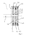
Figur 1- zeigt eine schematische Ansicht eines Dämpfungssystems gemäß einer Ausführungsform der Erfindung,
Figuren 2 bis 6- zeigen unterschiedliche Läufer-Pendellagerungen gemäß Ausführungsformen der Erfindung,
- Figur 7
- zeigt eine Querschnittsansicht eines Teils des Dämpfungssystems der
Figur 1 , - Figur 8
- zeigt eine Detailansicht aus
Figur 7 , und - Figur 9
- zeigt eine schematische Ansicht einer Antriebsvorrichtung mit dem
Dämpfungssystem der Figur 1 mit zugehöriger Verschaltung gemäß einer Ausführungsform der Erfindung.
- FIG. 1
- shows a schematic view of a damping system according to an embodiment of the invention,
- FIGS. 2 to 6
- show different rotor pendulum bearings according to embodiments of the invention,
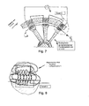
- FIG. 7
- shows a cross-sectional view of a part of the damping system of
FIG. 1 . - FIG. 8
- shows a detailed view
FIG. 7 , and - FIG. 9
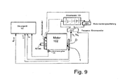
- shows a schematic view of a drive device with the damping system of
FIG. 1 with associated interconnection according to an embodiment of the invention.
Die in den Figuren gezeigten Ausführungsformen stimmen teilweise überein, so dass für gleiche oder ähnliche Teile die gleichen Bezugszeichen verwendet sind und zu deren Erläuterung auch auf die Beschreibung der anderen Ausführungsformen verwiesen wird, um Wiederholungen zu vermeiden.The embodiments shown in the figures are partially identical, so that the same reference numerals are used for the same or similar parts and reference is also made to the explanation of the other embodiments in order to avoid repetition.
Das Dämpfungssystem umfasst die Welle 1 (z. B. eine Antriebs- oder Kurbelwelle) und einen Dämpfer (D), wobei der Dämpfer (D) mittels der Welle 1 drehbare Dämpfer-Läufer 3.1 bis 3.3 und mittels der Welle 1 drehbare Läufer 4.1 bis 4.3 umfasst. Die Dämpfer-Läufer 3.1 bis 3.3 und die Läufer 4.1 bis 4.3 stellen Rotoren dar, die als Generatorläufer wirken.The damping system comprises the shaft 1 (eg a drive or crankshaft) and a damper (D), wherein the damper (D) by means of the
Die Läufer 4.1 bis 4.3 und die Dämpfer-Läufer 3.1 bis 3.3 sind zum induktiven Zusammenwirken ausgeführt, wozu sie wahlweise Spulen oder (Permanent-)Magnete und wahlweise Elektroterminals zur Erzeugung eins Magnetfelds umfassen können.The runners 4.1 to 4.3 and the damper rotor 3.1 to 3.3 are designed for inductive interaction, to which they may optionally comprise coils or (permanent) magnets and optionally electric terminals for generating a magnetic field.
Die Dämpfer-Läufer 3.1 bis 3.3 werden von einem Dämpfer-Gehäuse 2 getragen. Das Dämpfer-Gehäuse 2 ist starr an die Welle 1 und somit starr an die Drehbewegung der Welle 1 gekoppelt. Daraus folgt, dass die Dämpfer-Läufer 3.1 bis 3.3 ebenfalls starr an die Drehbewegung der Welle 1 gekoppelt sind und sich somit zumindest nahezu identisch zur Welle 1 drehen.The damper rotor 3.1 to 3.3 are supported by a
Die Läufer 4.1 bis 4.3 sind ebenfalls an die Drehbewegung der Welle 1 gekoppelt. Die Läufer 4.1 bis 4.3 umfassen allerdings Drehpendelarme und sind mittels Pendellagerungen 5.1 bis 5.3 pendelbar gelagert, um als Pendel wirken zu können. Dadurch kann die Drehbewegung der Welle 1 durch die Pendelbewegung der Läufer 4.1 bis 4.3 überlagert werden. Die Drehpendelarme erstrecken sich relativ zu der Welle 1 radial nach außen. Die Pendellagerungen 5.1 bis 5.3 sind auf einem starr mit der Welle 1 verbundenen Kopplungsteil 1' gelagert. Das Kopplungsteil 1' stellt eine axiale Verlängerung der Welle 1 und einen Teil des Dämpfer-Gehäuses 2 dar. Die Läufer 4.1 bis 4.3 sind im Innenraum des Dämpfer-Gehäuses 2 untergebracht. Das Kopplungsteil 1' kann ein zur Welle 1 separates Teil sein. Allerdings sind ebenso Ausführungsformen möglich, in denen zumindest eine Pendellagerung 5.1 bis 5.3 quasi direkt auf der Welle 1 gelagert ist. Im Rahmen der Erfindung können die Läufer 4.1 bis 4.3, insbesondere die Pendellagerungen 5.1 bis 5.3, somit direkt oder indirekt mit der Welle 1 verbunden sein.The runners 4.1 to 4.3 are also coupled to the rotational movement of the
Die Läufer 4.1 bis 4.3 wirken als Drehpendel und beeinflussen zusammen mit den Dämpfer-Läufern 3.1 bis 3.3 die Drehbewegung der Welle 1. Mittels einer in einem Magnetfeld stattfindenden Relativbewegung zwischen den Läufern 4.1 bis 4.3 und den Dämpfer-Läufern 3.1 bis 3.3, insbesondere der Auslenkung der pendelbaren Läufer 4.1 bis 4.3 innerhalb des Magnetfelds relativ zu den Dämpfer-Läufern 3.1 bis 3.3, kann die Schwingung der Welle 1 gedämpft und zugleich elektrische Energie mittels Induktion zurückgewonnen werden. Die Auslenkung der Läufer 4.1 bis 4.3 innerhalb des Magnetfelds führt somit zu einer dämpfenden Beeinflussung der Drehbewegung der Welle 1 und einer induktiven Energierückgewinnung. Mechanische Energie kann somit in elektrische Energie umgewandelt werden, anstatt als Abwärme oder Verlustenergie verloren zu gehen. Selbst ein Anregen und ein damit verbundenes Überschwingen der Läufer 4.1 bis 4.3 zur Krafteinleitung in die Welle 1 ist möglich.The runners 4.1 to 4.3 act as torsion pendulum and, together with the damper sliders 3.1 to 3.3, influence the rotational movement of the
Die Läufer 4.1 bis 4.3 und/oder die Dämpfer-Läufer 3.1 bis 3.3 können mittels eines Erregerstroms zum Aufbau des Magnetfelds veranlasst werden. Der Erregerstrom kann jede beliebige Zeitfunktion annehmen. Die Erreger-Zeitfunktion kann zumindest teilweise so gesteuert werden, dass sich eine maximale Drehschwingungsdämpfung und damit eine maximal rückführbare Energie ergeben. Ebenso kann die Steuerung der rückgeführten Energie diese Maximierung übernehmen. Kombinationen aus beiden Regel-/Steuerstrategien sind möglich.The rotor 4.1 to 4.3 and / or the damper rotor 3.1 to 3.3 can be caused by means of an excitation current to build up the magnetic field. The excitation current can take on any time function. The exciter-time function can be at least partially controlled so that there is a maximum torsional vibration damping and thus a maximum traceable energy. Likewise, the control of the recirculated energy can take over this maximization. Combinations of both control strategies are possible.
Die Pendellagerungen 5.1 bis 5.3 verfügen über eine Federsteifigkeit, so dass, in Zusammenhang mit den beteiligten Massenträgheitsmomenten, ein zusätzlicher Tilgereffekt in mindestens einem speziellem Frequenzbereich erzeugt werden kann.The pendulum bearings 5.1 to 5.3 have a spring stiffness, so that, in connection with the mass moments of inertia involved, an additional Tilgereffekt can be generated in at least one specific frequency range.
Als energierückspeisendes Teil des Dämpfungssystems kann ein in
Die zurückgewonnene Energie aus dem Dämpfungssystem kann in andere Energieformen umgewandelt werden, sie kann zumindest teilweise gespeichert werden oder dem Dämpfungssystem oder allgemein dem Kraftfahrzeug als zusätzliche Nutzoder Antriebsenergie oder anderen Aggregaten zur Verfügung gestellt werden.The recovered energy from the damping system may be converted to other forms of energy, at least partially stored, or provided to the damping system or generally to the motor vehicle as additional useful or propulsion energy or other aggregates.
In dem in
Die Läufer 4.1 bis 4.3 sind allesamt über die Pendellagerungen 5.1 bis 5.3 an das Kopplungsteil 1' gekoppelt. In einem nicht gezeigten Ausführungsbeispiel ist es allerdings möglich, dass ein Läufer an einen pendelbaren Läufer gekoppelt ist und letztgenannte Läufer-Kombination über ein und dieselbe Pendellagerung an die Drehbewegung der Welle 1 gekoppelt ist.The runners 4.1 to 4.3 are all coupled via the pendulum bearings 5.1 to 5.3 to the coupling part 1 '. In an embodiment, not shown, however, it is possible that a runner is coupled to a pendulum runner and the latter Runner combination is coupled via one and the same pendulum bearing to the rotational movement of the
Die Läufer 4.1 bis 4.3 bzw. die Dämpfer-Läufer 3.1 bis 3.3 können über ein und dasselbe Elektroterminal mit elektrischer Energie (Strom und/oder Spannung) versorgt werden oder über verschiedene Elektroterminals, wodurch Magnetfelder örtlich unterschiedlich ausgebildet werden können.The runners 4.1 to 4.3 or the damper runners 3.1 to 3.3 can be supplied via one and the same electrical terminal with electrical energy (power and / or voltage) or via various electrical terminals, whereby magnetic fields can be locally formed differently.
Dem Dämpfungssystem kann ferner über das oder die Elektroterminal(s) ein Energieeintrag zugeführt werden, durch einen Impuls, der zu einem Überschwingen der Läufer 4.1 bis 4.3 führt und der Welle 1 damit eine Kraft aufprägt oder induziert.The damping system can also be supplied via the or the electric terminal (s) an energy input, by a pulse that leads to an overshoot of the rotor 4.1 to 4.3 and the
Mittels der unterschiedlichen und/oder variablen Gestaltung der Magnetfelder kann der Wirkungsgrad der Umwandlung der unerwünschten Drehschwingungen in elektrische Energie verändert oder optimiert werden. Dazu kann grundsätzlich gelten:
- Höhere Wellen- oder Motordrehzahl führt zur Aktivierung der steiferen Läufer (Pendel) 4.1 bis 4.3,
- Niedrigere Wellen- oder Motordrehzahl führt zur Aktivierung der weicheren Läufer (Pendel) 4.1 bis 4.3,
- Höhere Wellen- oder Motordrehzahl führt zur Aktivierung der Läufer (Pendel) 4.1 bis 4.3 mit geringerer Masse,
- Niedrigere Wellen- oder Motordrehzahl führt zur Aktivierung der Läufer (Pendel) 4.1 bis 4.3 mit höherer Masse.
- Higher shaft or engine speed leads to the activation of the stiffer rotor (pendulum) 4.1 to 4.3,
- Lower shaft or engine speed leads to activation of the softer runners (pendulum) 4.1 to 4.3,
- Higher shaft or motor speed leads to the activation of the pendulum (pendulum) 4.1 to 4.3 with lower mass,
- Lower shaft or motor speed activates the pendulum (pendulum) 4.1 to 4.3 with higher mass.
Diese Verhältnisse gelten sowohl bei Energieeintrag als auch bei Energieaustrag.These conditions apply to both energy input and energy discharge.
Die Bestromung und/oder Aktivierung der zweckmäßig unterschiedlichen Magnetfelder kann über eine Regelung oder Steuerung erfolgen, welche zumindest einenThe energization and / or activation of the appropriately different magnetic fields can be done via a control or control, which at least one
Sensor für die segmentzeitabhängige Drehzahlerfassung verwendet. Letztgenannter Sensor kann zweckmäßig ein "Unrundlaufen oder Drehschwingungen" detektieren und folglich auch die Wirkungsweise des Dämpfungssystems überwachen und/oder steuern.
-
Figur 2 -
Figur 3 zeigt eine als Federlagerung ausgeführte Pendellagerung. Die Federlagerung zeichnet sich durch Folgendes aus: angekoppelt über Drehfedern der Steifigkeit C > 0, Dämpfung D gering. -
Figur 4 -
Figur 5 zeigt eine als Hydrauliklagerung ausgeführte Pendellagerung. Die Hydrauliklagerung zeichnet sich durch Folgendes aus: hydraulisch angekoppelt, Steifigkeit C und Dämpfung D über (Spalt-)Maß S und Viskosität des Fluids einstellbar, Steifigkeit C und Dämpfung D können durch Verdrängen des Fluids und/oder Fluidscherung erzeugt werden. -
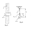
Figur 6 zeigt eine Pendellagerung, die inRadialrichtung der Welle 1 oder des Kopplungsteils 1' vom Außenumfang derselben beabstandet ist. Diese Pendellagerung zeichnet sich durch zumindest eines von Folgenden aus: drehzahladaptiv, Tilgerfrequenz folgt der Rotationsfrequenz derWelle 1 und damit des Dämpfer-Gehäuses 2 mit Faktor f, wobei f durch das Verhältnis L2/L1 sowie DI, CI (Dämpfung und Steifigkeit der Pendellagerung) einstellbar ist. -
Figur 7 zeigt eine Querschnittsansicht eines Teils des Dämpfungssystems derFigur 1 , währendFigur 8 die Detailansicht A ausFigur 7 darstellt.
-
FIG. 2 shows a designed as a rotary bearing pendulum bearing. The pivot bearing is characterized by the following: freely rotatable, rigidity C = 0, damping D = 0 or at least low, no damping effect due to the pendulum bearing. -
FIG. 3 shows a designed as a spring bearing pendulum bearing. The spring bearing is characterized by the following: Coupled via torsion springs of stiffness C> 0, damping D low. -
FIG. 4 shows a designed as an elastomeric bearing pendulum bearing. The self-aligning bearing is characterized by the following: Coupling by elastomer torsion springs, stiffness C> 0 and adjustable via the shape and / or Shore hardness of the elastomer torsion springs, damping D adjustable via loss factor of the elastomer. -
FIG. 5 shows a running as a hydraulic bearing pendulum bearing. The hydraulic bearing is characterized by the following: hydraulically coupled, stiffness C and damping D adjustable via (gap) dimension S and viscosity of the fluid, stiffness C and damping D can be generated by displacing the fluid and / or fluid shear. -
FIG. 6 shows a pendulum bearing, which is spaced in the radial direction of theshaft 1 or the coupling part 1 'from the outer periphery thereof. This pendulum bearing is characterized by at least one of the following: speed adaptive, absorber frequency follows the rotation frequency of theshaft 1 and thus thedamper housing 2 with factor f, where f by the ratio L 2 / L 1 and D I , C I (damping and Stiffness of the pendulum bearing) is adjustable. -
FIG. 7 shows a cross-sectional view of a part of the damping system ofFIG. 1 , whileFIG. 8 the detail view A fromFIG. 7 represents.
Unter Bezugnahme auf die
Die Antriebsvorrichtung für ein Fahrzeug umfasst einen als Brennkraftmaschine ausgebildeten Wellenantriebsmotor (102) mit einer als Kurbelwelle ausgebildeten Welle (1), ein auf der kraftabgebenden Seite der Brennkraftmaschine im Bereich eines axialen Endes der Brennkraftmaschine angeordnetes Schwungrad (nicht dargestellt) und ein Dämpfungssystem. Der Dämpfer (D) des Dämpfungssystems ist an dem dem Schwungrad gegenüberliegenden axialen Ende der Kurbelwelle angeordnet. Ein Steuergerät 101 bekommt von einer Erfassungseinrichtung 103 zum Erfassen einer Drehungleichförmigkeit der Kurbelwelle oder der Brennkraftmaschine Informationen über die Drehungleichförmigkeit. Die Erfassungseinrichtung 103 kann als Impuls- oder Inkrementgeber ausgeführt sein. Das Steuergerät 101 steuert danach die Spannung Uer und den Strom Ier so, dass die Stromstärke Iab und die Spannung Uab im zugehörigen Betriebspunkt zweckmäßig maximal werden. Damit kann auch die Dämpfung des Dämpfungssystems zweckmäßig maximiert werden. Ein Frequenz-/Stromwandler 105 passt den Spannungs-/Stromverlauf so an, dass ein Akkumulator 104 und ein Energie-Rückspeisungsmodul 106 optimal gespeist werden. Eine Einrichtung 107 zur Leistungsaufteilung steuert die Energiebilanz auf den Akkumulator 104 und das Rückspeisungsmodul 106 und kann aktiv, durch Phasenversatz, Drehschwingungen am Abtrieb und/oder durch modulierte Leistungsabgabe auf das Rückspeisemodul 106 zusätzlich wirksam reduziert werden.The drive device for a vehicle comprises a shaft drive motor (102) designed as an internal combustion engine with a shaft (1) designed as a crankshaft, a flywheel (not shown) arranged on the force-emitting side of the internal combustion engine in the region of an axial end of the internal combustion engine and a damping system. The damper (D) of the damping system is arranged on the axial end of the crankshaft opposite the flywheel. A controller 101 obtains information about the rotational nonuniformity from a detection means 103 for detecting rotational nonuniformity of the crankshaft or the engine. The
Durch die Anordnung des Dämpfers (D) eines derartigen Dämpfungssystems im Bereich des dem Schwungrad gegenüberliegenden axialen Endes der Kurbelwelle werden Torsionsschwingungen der Kurbelwelle reduziert, wodurch auch Torsionsbrüche vermieden werden. Zudem wird die Drehschwingungsanregung des Steuerrädertriebs (nicht dargestellt) der Brennkraftmaschine minimiert. Dies reduziert die Lautstärke der Brennkraftmaschine. Darüber hinaus wird eine Verringerung der Drehungleichförmigkeit der Kurbelwelle sowie der aus der Massendynamik resultierenden Massenkräfte, welche als Drehmomentschwankungen auf die Kurbelwelle wirken, erreicht.The arrangement of the damper (D) of such a damping system in the region of the flywheel opposite axial end of the crankshaft torsional vibrations of the crankshaft are reduced, whereby torsional fractures are avoided. In addition, the torsional vibration excitation of the Steuerrädertriebs (not shown) of the internal combustion engine is minimized. This reduces the volume of the internal combustion engine. In addition, a reduction in the Nonuniformity of the crankshaft and the mass forces resulting from the mass dynamics, which act as torque fluctuations on the crankshaft reached.
Mittels der Drehschwingungsdämpfung des Dämpfungssystems kann ferner z. B. Folgendes realisiert werden: eine leichter gebaute Kurbelwelle, eine Entlastung von Riemenspannern im Riementrieb und/oder akustische Verbesserungen durch gleichmäßigere Befeuerung der Kraftfahrzeug-Zylinder.By means of the torsional vibration damping of the damping system can also z. For example, the following can be realized: a lighter-built crankshaft, a relief of belt tensioners in the belt drive and / or acoustic improvements by more uniform firing of the motor vehicle cylinder.
Die Erfindung ist nicht auf die oben beschriebenen bevorzugten Ausführungsformen beschränkt. Vielmehr ist eine Vielzahl von Varianten und Abwandlungen möglich, die ebenfalls von dem Erfindungsgedanken Gebrauch machen und deshalb in den Schutzbereich fallen. Darüber hinaus beansprucht die Erfindung auch Schutz für den Gegenstand und die Merkmale der Unteransprüche, unabhängig von den in Bezug genommenen Merkmalen und Ansprüchen.The invention is not limited to the preferred embodiments described above. Rather, a variety of variants and modifications are possible, which also make use of the concept of the invention and therefore fall within the scope. Moreover, the invention also claims protection for the subject matter and the features of the subclaims, independently of the features and claims referred to.
- 11
- Wellewave
- 1'1'
- Kopplungsteil, z. B. WellenverlängerungCoupling part, z. B. shaft extension
- 22
- Dämpfer-GehäuseDamper housing
- 3.1 bis 3.33.1 to 3.3
- Dämpfer-LäuferDamper Runner
- 4.1 bis 4.34.1 to 4.3
- Pendelbarer LäuferPendulum runner
- 5.1 bis 5.35.1 to 5.3
- Pendellagerungself-aligning bearing
- 6.1 bis 6.36.1 to 6.3
- Luftspaltair gap
- 101101
- Steuergerätcontrol unit
- 102102
- Wellen-AntriebsmotorShaft drive motor
- 103103
- Erfassungseinrichtungdetector
- 104104
- Akkumulatoraccumulator
- 105105
- Frequenz-/StromwandlerFrequency / CT
- 106106
- Energie-RückspeisemodulEnergy recovery module
- 107107
- Einrichtung zur LeistungsaufteilungDevice for power distribution
- DD
- Dämpferdamper
- UU
- Spannungtension
- II
- Stromstärkeamperage
Claims (17)
Applications Claiming Priority (1)
| Application Number | Priority Date | Filing Date | Title |
|---|---|---|---|
| DE102014001425.8A DE102014001425A1 (en) | 2014-02-05 | 2014-02-05 | Damping system with energy recovery for a motor vehicle |
Publications (3)
| Publication Number | Publication Date |
|---|---|
| EP2910813A2 true EP2910813A2 (en) | 2015-08-26 |
| EP2910813A3 EP2910813A3 (en) | 2016-02-24 |
| EP2910813B1 EP2910813B1 (en) | 2019-07-17 |
Family
ID=52144345
Family Applications (1)
| Application Number | Title | Priority Date | Filing Date |
|---|---|---|---|
| EP14004206.0A Active EP2910813B1 (en) | 2014-02-05 | 2014-12-12 | Damping system with energy recovery for a motor vehicle and drive device using such a damping system |
Country Status (2)
| Country | Link |
|---|---|
| EP (1) | EP2910813B1 (en) |
| DE (1) | DE102014001425A1 (en) |
Cited By (1)
| Publication number | Priority date | Publication date | Assignee | Title |
|---|---|---|---|---|
| ITUB20156847A1 (en) * | 2015-12-11 | 2017-06-11 | Fpt Motorenforschung Ag | DAMPER TO DAMPEN VIBRATIONS OF A CRANKSHAFT |
Citations (1)
| Publication number | Priority date | Publication date | Assignee | Title |
|---|---|---|---|---|
| DE102009011084A1 (en) | 2008-12-19 | 2010-06-24 | Robert Bosch Gmbh | Stationary power generation plant with a device for damping mechanical vibrations |
Family Cites Families (2)
| Publication number | Priority date | Publication date | Assignee | Title |
|---|---|---|---|---|
| DE4447537B4 (en) * | 1994-02-28 | 2006-04-20 | Temic Automotive Electric Motors Gmbh | Method and system for active vibration damping |
| DE102010029844A1 (en) * | 2010-06-09 | 2011-12-15 | Robert Bosch Gmbh | Device for damping and energy recovery for internal combustion engines |
-
2014
- 2014-02-05 DE DE102014001425.8A patent/DE102014001425A1/en not_active Withdrawn
- 2014-12-12 EP EP14004206.0A patent/EP2910813B1/en active Active
Patent Citations (1)
| Publication number | Priority date | Publication date | Assignee | Title |
|---|---|---|---|---|
| DE102009011084A1 (en) | 2008-12-19 | 2010-06-24 | Robert Bosch Gmbh | Stationary power generation plant with a device for damping mechanical vibrations |
Cited By (2)
| Publication number | Priority date | Publication date | Assignee | Title |
|---|---|---|---|---|
| ITUB20156847A1 (en) * | 2015-12-11 | 2017-06-11 | Fpt Motorenforschung Ag | DAMPER TO DAMPEN VIBRATIONS OF A CRANKSHAFT |
| EP3179131A1 (en) * | 2015-12-11 | 2017-06-14 | FPT Motorenforschung AG | Damper for damping torsional vibrations of a crankshaft |
Also Published As
| Publication number | Publication date |
|---|---|
| DE102014001425A1 (en) | 2015-08-06 |
| EP2910813B1 (en) | 2019-07-17 |
| EP2910813A3 (en) | 2016-02-24 |
Similar Documents
| Publication | Publication Date | Title |
|---|---|---|
| EP3233601B1 (en) | Actuator arrangement for applying a torque to a shaft, in particular a crankshaft of a reciprocating piston engine, and a corresponding method | |
| EP0916040B2 (en) | Electric machine in a driving train, for example of a motor vehicle, and process for driving the same | |
| EP0845088B1 (en) | System for actively reducing radial vibrations in a rotating shaft, and method of operating the system to achieve this | |
| EP2726353B1 (en) | Hybrid drive train having an active torsional vibration damping and method for carrying out the active torsional vibration damping | |
| EP1687887B1 (en) | Electric motor for an electrical small-scale unit | |
| EP2911928B1 (en) | Method for damping torsional vibration in a drive train | |
| DE10213595A1 (en) | Vehicle center bearing arrangement including a piezo-based device for vibration damping | |
| EP3243011B1 (en) | Integrated double elastic active part disconnection | |
| WO1997021560A1 (en) | Motor vehicle with electrical generator | |
| DE102009001163A1 (en) | Piezoelectric generator for drive device of vehicle, particularly motor vehicle for electricity generation, has piezo unit which is tensed for generating alternating current periodically | |
| EP2910813B1 (en) | Damping system with energy recovery for a motor vehicle and drive device using such a damping system | |
| EP3021007A1 (en) | Device and method for reducing gear wheel noise | |
| EP0429785A2 (en) | Test bench for a torsional vibration absorber | |
| DE102013100964B4 (en) | Method for the active damping of torsional vibrations of a shaft of a machine, in particular a crankshaft of a reciprocating piston machine, | |
| WO2005119085A1 (en) | Method and device for damping torsional vibrations and rotational irregularities in drive trains | |
| AT512516A4 (en) | Vibration damping for a range extender | |
| DE102014219604A1 (en) | Lifting system, electrical testing method, vibration damper and machine unit | |
| DE102012113035A1 (en) | Device for optimization of noise in interior of vehicle, has engine mounting element comprising actuator which is controlled as vibration generator such that it generates vibration | |
| EP0603527B1 (en) | Vibration motor | |
| WO2021110203A1 (en) | Electric axial-flow machine and drive system | |
| DE102012208285B3 (en) | Energy recovery system for vehicle i.e. motor car, has hydraulic cylinder provided as power supply, and oscillator comprising dielectric elastomer converting pressure into electrical power and actuated in range of natural frequency | |
| DE102014217363B4 (en) | METHOD AND DEVICE ON ROTOR SYSTEMS | |
| DE10053114C1 (en) | Device for damping the vibration of an oscillating unit | |
| DE10010095B4 (en) | Crankshaft with high vibration damping | |
| WO2012065796A1 (en) | Device for actively reducing mechanical oscillation |
Legal Events
| Date | Code | Title | Description |
|---|---|---|---|
| PUAI | Public reference made under article 153(3) epc to a published international application that has entered the european phase |
Free format text: ORIGINAL CODE: 0009012 |
|
| AK | Designated contracting states |
Kind code of ref document: A2 Designated state(s): AL AT BE BG CH CY CZ DE DK EE ES FI FR GB GR HR HU IE IS IT LI LT LU LV MC MK MT NL NO PL PT RO RS SE SI SK SM TR |
|
| AX | Request for extension of the european patent |
Extension state: BA ME |
|
| PUAL | Search report despatched |
Free format text: ORIGINAL CODE: 0009013 |
|
| AK | Designated contracting states |
Kind code of ref document: A3 Designated state(s): AL AT BE BG CH CY CZ DE DK EE ES FI FR GB GR HR HU IE IS IT LI LT LU LV MC MK MT NL NO PL PT RO RS SE SI SK SM TR |
|
| AX | Request for extension of the european patent |
Extension state: BA ME |
|
| RIC1 | Information provided on ipc code assigned before grant |
Ipc: F16F 15/14 20060101AFI20160115BHEP Ipc: F16F 15/30 20060101ALI20160115BHEP Ipc: F16F 15/18 20060101ALI20160115BHEP |
|
| 17P | Request for examination filed |
Effective date: 20160606 |
|
| GRAP | Despatch of communication of intention to grant a patent |
Free format text: ORIGINAL CODE: EPIDOSNIGR1 |
|
| STAA | Information on the status of an ep patent application or granted ep patent |
Free format text: STATUS: GRANT OF PATENT IS INTENDED |
|
| INTG | Intention to grant announced |
Effective date: 20190122 |
|
| GRAS | Grant fee paid |
Free format text: ORIGINAL CODE: EPIDOSNIGR3 |
|
| GRAJ | Information related to disapproval of communication of intention to grant by the applicant or resumption of examination proceedings by the epo deleted |
Free format text: ORIGINAL CODE: EPIDOSDIGR1 |
|
| GRAL | Information related to payment of fee for publishing/printing deleted |
Free format text: ORIGINAL CODE: EPIDOSDIGR3 |
|
| STAA | Information on the status of an ep patent application or granted ep patent |
Free format text: STATUS: REQUEST FOR EXAMINATION WAS MADE |
|
| GRAR | Information related to intention to grant a patent recorded |
Free format text: ORIGINAL CODE: EPIDOSNIGR71 |
|
| STAA | Information on the status of an ep patent application or granted ep patent |
Free format text: STATUS: GRANT OF PATENT IS INTENDED |
|
| GRAA | (expected) grant |
Free format text: ORIGINAL CODE: 0009210 |
|
| STAA | Information on the status of an ep patent application or granted ep patent |
Free format text: STATUS: THE PATENT HAS BEEN GRANTED |
|
| INTC | Intention to grant announced (deleted) | ||
| INTG | Intention to grant announced |
Effective date: 20190605 |
|
| AK | Designated contracting states |
Kind code of ref document: B1 Designated state(s): AL AT BE BG CH CY CZ DE DK EE ES FI FR GB GR HR HU IE IS IT LI LT LU LV MC MK MT NL NO PL PT RO RS SE SI SK SM TR |
|
| RAP1 | Party data changed (applicant data changed or rights of an application transferred) |
Owner name: MAN TRUCK & BUS SE |
|
| REG | Reference to a national code |
Ref country code: GB Ref legal event code: FG4D Free format text: NOT ENGLISH |
|
| REG | Reference to a national code |
Ref country code: CH Ref legal event code: EP |
|
| REG | Reference to a national code |
Ref country code: IE Ref legal event code: FG4D Free format text: LANGUAGE OF EP DOCUMENT: GERMAN |
|
| REG | Reference to a national code |
Ref country code: DE Ref legal event code: R096 Ref document number: 502014012208 Country of ref document: DE |
|
| REG | Reference to a national code |
Ref country code: AT Ref legal event code: REF Ref document number: 1156143 Country of ref document: AT Kind code of ref document: T Effective date: 20190815 |
|
| REG | Reference to a national code |
Ref country code: NL Ref legal event code: FP |
|
| REG | Reference to a national code |
Ref country code: SE Ref legal event code: TRGR |
|
| REG | Reference to a national code |
Ref country code: LT Ref legal event code: MG4D |
|
| PG25 | Lapsed in a contracting state [announced via postgrant information from national office to epo] |
Ref country code: NO Free format text: LAPSE BECAUSE OF FAILURE TO SUBMIT A TRANSLATION OF THE DESCRIPTION OR TO PAY THE FEE WITHIN THE PRESCRIBED TIME-LIMIT Effective date: 20191017 Ref country code: BG Free format text: LAPSE BECAUSE OF FAILURE TO SUBMIT A TRANSLATION OF THE DESCRIPTION OR TO PAY THE FEE WITHIN THE PRESCRIBED TIME-LIMIT Effective date: 20191017 Ref country code: LT Free format text: LAPSE BECAUSE OF FAILURE TO SUBMIT A TRANSLATION OF THE DESCRIPTION OR TO PAY THE FEE WITHIN THE PRESCRIBED TIME-LIMIT Effective date: 20190717 Ref country code: PT Free format text: LAPSE BECAUSE OF FAILURE TO SUBMIT A TRANSLATION OF THE DESCRIPTION OR TO PAY THE FEE WITHIN THE PRESCRIBED TIME-LIMIT Effective date: 20191118 Ref country code: HR Free format text: LAPSE BECAUSE OF FAILURE TO SUBMIT A TRANSLATION OF THE DESCRIPTION OR TO PAY THE FEE WITHIN THE PRESCRIBED TIME-LIMIT Effective date: 20190717 Ref country code: FI Free format text: LAPSE BECAUSE OF FAILURE TO SUBMIT A TRANSLATION OF THE DESCRIPTION OR TO PAY THE FEE WITHIN THE PRESCRIBED TIME-LIMIT Effective date: 20190717 |
|
| PG25 | Lapsed in a contracting state [announced via postgrant information from national office to epo] |
Ref country code: AL Free format text: LAPSE BECAUSE OF FAILURE TO SUBMIT A TRANSLATION OF THE DESCRIPTION OR TO PAY THE FEE WITHIN THE PRESCRIBED TIME-LIMIT Effective date: 20190717 Ref country code: ES Free format text: LAPSE BECAUSE OF FAILURE TO SUBMIT A TRANSLATION OF THE DESCRIPTION OR TO PAY THE FEE WITHIN THE PRESCRIBED TIME-LIMIT Effective date: 20190717 Ref country code: GR Free format text: LAPSE BECAUSE OF FAILURE TO SUBMIT A TRANSLATION OF THE DESCRIPTION OR TO PAY THE FEE WITHIN THE PRESCRIBED TIME-LIMIT Effective date: 20191018 Ref country code: IS Free format text: LAPSE BECAUSE OF FAILURE TO SUBMIT A TRANSLATION OF THE DESCRIPTION OR TO PAY THE FEE WITHIN THE PRESCRIBED TIME-LIMIT Effective date: 20191117 Ref country code: RS Free format text: LAPSE BECAUSE OF FAILURE TO SUBMIT A TRANSLATION OF THE DESCRIPTION OR TO PAY THE FEE WITHIN THE PRESCRIBED TIME-LIMIT Effective date: 20190717 Ref country code: LV Free format text: LAPSE BECAUSE OF FAILURE TO SUBMIT A TRANSLATION OF THE DESCRIPTION OR TO PAY THE FEE WITHIN THE PRESCRIBED TIME-LIMIT Effective date: 20190717 |
|
| PG25 | Lapsed in a contracting state [announced via postgrant information from national office to epo] |
Ref country code: TR Free format text: LAPSE BECAUSE OF FAILURE TO SUBMIT A TRANSLATION OF THE DESCRIPTION OR TO PAY THE FEE WITHIN THE PRESCRIBED TIME-LIMIT Effective date: 20190717 |
|
| PG25 | Lapsed in a contracting state [announced via postgrant information from national office to epo] |
Ref country code: RO Free format text: LAPSE BECAUSE OF FAILURE TO SUBMIT A TRANSLATION OF THE DESCRIPTION OR TO PAY THE FEE WITHIN THE PRESCRIBED TIME-LIMIT Effective date: 20190717 Ref country code: DK Free format text: LAPSE BECAUSE OF FAILURE TO SUBMIT A TRANSLATION OF THE DESCRIPTION OR TO PAY THE FEE WITHIN THE PRESCRIBED TIME-LIMIT Effective date: 20190717 Ref country code: EE Free format text: LAPSE BECAUSE OF FAILURE TO SUBMIT A TRANSLATION OF THE DESCRIPTION OR TO PAY THE FEE WITHIN THE PRESCRIBED TIME-LIMIT Effective date: 20190717 Ref country code: PL Free format text: LAPSE BECAUSE OF FAILURE TO SUBMIT A TRANSLATION OF THE DESCRIPTION OR TO PAY THE FEE WITHIN THE PRESCRIBED TIME-LIMIT Effective date: 20190717 |
|
| PG25 | Lapsed in a contracting state [announced via postgrant information from national office to epo] |
Ref country code: CZ Free format text: LAPSE BECAUSE OF FAILURE TO SUBMIT A TRANSLATION OF THE DESCRIPTION OR TO PAY THE FEE WITHIN THE PRESCRIBED TIME-LIMIT Effective date: 20190717 Ref country code: SK Free format text: LAPSE BECAUSE OF FAILURE TO SUBMIT A TRANSLATION OF THE DESCRIPTION OR TO PAY THE FEE WITHIN THE PRESCRIBED TIME-LIMIT Effective date: 20190717 Ref country code: SM Free format text: LAPSE BECAUSE OF FAILURE TO SUBMIT A TRANSLATION OF THE DESCRIPTION OR TO PAY THE FEE WITHIN THE PRESCRIBED TIME-LIMIT Effective date: 20190717 Ref country code: IS Free format text: LAPSE BECAUSE OF FAILURE TO SUBMIT A TRANSLATION OF THE DESCRIPTION OR TO PAY THE FEE WITHIN THE PRESCRIBED TIME-LIMIT Effective date: 20200224 |
|
| REG | Reference to a national code |
Ref country code: DE Ref legal event code: R097 Ref document number: 502014012208 Country of ref document: DE |
|
| PLBE | No opposition filed within time limit |
Free format text: ORIGINAL CODE: 0009261 |
|
| STAA | Information on the status of an ep patent application or granted ep patent |
Free format text: STATUS: NO OPPOSITION FILED WITHIN TIME LIMIT |
|
| PG2D | Information on lapse in contracting state deleted |
Ref country code: IS |
|
| REG | Reference to a national code |
Ref country code: CH Ref legal event code: PL |
|
| 26N | No opposition filed |
Effective date: 20200603 |
|
| REG | Reference to a national code |
Ref country code: BE Ref legal event code: MM Effective date: 20191231 |
|
| PG25 | Lapsed in a contracting state [announced via postgrant information from national office to epo] |
Ref country code: SI Free format text: LAPSE BECAUSE OF FAILURE TO SUBMIT A TRANSLATION OF THE DESCRIPTION OR TO PAY THE FEE WITHIN THE PRESCRIBED TIME-LIMIT Effective date: 20190717 Ref country code: MC Free format text: LAPSE BECAUSE OF FAILURE TO SUBMIT A TRANSLATION OF THE DESCRIPTION OR TO PAY THE FEE WITHIN THE PRESCRIBED TIME-LIMIT Effective date: 20190717 |
|
| GBPC | Gb: european patent ceased through non-payment of renewal fee |
Effective date: 20191212 |
|
| PG25 | Lapsed in a contracting state [announced via postgrant information from national office to epo] |
Ref country code: IE Free format text: LAPSE BECAUSE OF NON-PAYMENT OF DUE FEES Effective date: 20191212 Ref country code: GB Free format text: LAPSE BECAUSE OF NON-PAYMENT OF DUE FEES Effective date: 20191212 Ref country code: LU Free format text: LAPSE BECAUSE OF NON-PAYMENT OF DUE FEES Effective date: 20191212 |
|
| PG25 | Lapsed in a contracting state [announced via postgrant information from national office to epo] |
Ref country code: LI Free format text: LAPSE BECAUSE OF NON-PAYMENT OF DUE FEES Effective date: 20191231 Ref country code: BE Free format text: LAPSE BECAUSE OF NON-PAYMENT OF DUE FEES Effective date: 20191231 Ref country code: CH Free format text: LAPSE BECAUSE OF NON-PAYMENT OF DUE FEES Effective date: 20191231 |
|
| REG | Reference to a national code |
Ref country code: AT Ref legal event code: MM01 Ref document number: 1156143 Country of ref document: AT Kind code of ref document: T Effective date: 20191212 |
|
| PG25 | Lapsed in a contracting state [announced via postgrant information from national office to epo] |
Ref country code: AT Free format text: LAPSE BECAUSE OF NON-PAYMENT OF DUE FEES Effective date: 20191212 Ref country code: CY Free format text: LAPSE BECAUSE OF FAILURE TO SUBMIT A TRANSLATION OF THE DESCRIPTION OR TO PAY THE FEE WITHIN THE PRESCRIBED TIME-LIMIT Effective date: 20190717 |
|
| PG25 | Lapsed in a contracting state [announced via postgrant information from national office to epo] |
Ref country code: HU Free format text: LAPSE BECAUSE OF FAILURE TO SUBMIT A TRANSLATION OF THE DESCRIPTION OR TO PAY THE FEE WITHIN THE PRESCRIBED TIME-LIMIT; INVALID AB INITIO Effective date: 20141212 Ref country code: MT Free format text: LAPSE BECAUSE OF FAILURE TO SUBMIT A TRANSLATION OF THE DESCRIPTION OR TO PAY THE FEE WITHIN THE PRESCRIBED TIME-LIMIT Effective date: 20190717 |
|
| PG25 | Lapsed in a contracting state [announced via postgrant information from national office to epo] |
Ref country code: MK Free format text: LAPSE BECAUSE OF FAILURE TO SUBMIT A TRANSLATION OF THE DESCRIPTION OR TO PAY THE FEE WITHIN THE PRESCRIBED TIME-LIMIT Effective date: 20190717 |
|
| PGFP | Annual fee paid to national office [announced via postgrant information from national office to epo] |
Ref country code: DE Payment date: 20221227 Year of fee payment: 9 |
|
| PGFP | Annual fee paid to national office [announced via postgrant information from national office to epo] |
Ref country code: SE Payment date: 20231222 Year of fee payment: 10 Ref country code: NL Payment date: 20231226 Year of fee payment: 10 Ref country code: IT Payment date: 20231221 Year of fee payment: 10 Ref country code: FR Payment date: 20231226 Year of fee payment: 10 |
|
| PGFP | Annual fee paid to national office [announced via postgrant information from national office to epo] |
Ref country code: DE Payment date: 20231227 Year of fee payment: 10 |