EP2910740A1 - Variable vane sychronization ring transmission mechanisms - Google Patents
Variable vane sychronization ring transmission mechanisms Download PDFInfo
- Publication number
- EP2910740A1 EP2910740A1 EP15156166.9A EP15156166A EP2910740A1 EP 2910740 A1 EP2910740 A1 EP 2910740A1 EP 15156166 A EP15156166 A EP 15156166A EP 2910740 A1 EP2910740 A1 EP 2910740A1
- Authority
- EP
- European Patent Office
- Prior art keywords
- ring
- sun gear
- gear teeth
- gear
- teeth
- Prior art date
- Legal status (The legal status is an assumption and is not a legal conclusion. Google has not performed a legal analysis and makes no representation as to the accuracy of the status listed.)
- Granted
Links
Images


Classifications
-
- F—MECHANICAL ENGINEERING; LIGHTING; HEATING; WEAPONS; BLASTING
- F01—MACHINES OR ENGINES IN GENERAL; ENGINE PLANTS IN GENERAL; STEAM ENGINES
- F01D—NON-POSITIVE DISPLACEMENT MACHINES OR ENGINES, e.g. STEAM TURBINES
- F01D17/00—Regulating or controlling by varying flow
- F01D17/10—Final actuators
- F01D17/12—Final actuators arranged in stator parts
-
- F—MECHANICAL ENGINEERING; LIGHTING; HEATING; WEAPONS; BLASTING
- F01—MACHINES OR ENGINES IN GENERAL; ENGINE PLANTS IN GENERAL; STEAM ENGINES
- F01D—NON-POSITIVE DISPLACEMENT MACHINES OR ENGINES, e.g. STEAM TURBINES
- F01D17/00—Regulating or controlling by varying flow
- F01D17/10—Final actuators
- F01D17/12—Final actuators arranged in stator parts
- F01D17/14—Final actuators arranged in stator parts varying effective cross-sectional area of nozzles or guide conduits
- F01D17/16—Final actuators arranged in stator parts varying effective cross-sectional area of nozzles or guide conduits by means of nozzle vanes
- F01D17/162—Final actuators arranged in stator parts varying effective cross-sectional area of nozzles or guide conduits by means of nozzle vanes for axial flow, i.e. the vanes turning around axes which are essentially perpendicular to the rotor centre line
-
- F—MECHANICAL ENGINEERING; LIGHTING; HEATING; WEAPONS; BLASTING
- F01—MACHINES OR ENGINES IN GENERAL; ENGINE PLANTS IN GENERAL; STEAM ENGINES
- F01D—NON-POSITIVE DISPLACEMENT MACHINES OR ENGINES, e.g. STEAM TURBINES
- F01D9/00—Stators
- F01D9/02—Nozzles; Nozzle boxes; Stator blades; Guide conduits, e.g. individual nozzles
- F01D9/04—Nozzles; Nozzle boxes; Stator blades; Guide conduits, e.g. individual nozzles forming ring or sector
- F01D9/041—Nozzles; Nozzle boxes; Stator blades; Guide conduits, e.g. individual nozzles forming ring or sector using blades
-
- F—MECHANICAL ENGINEERING; LIGHTING; HEATING; WEAPONS; BLASTING
- F16—ENGINEERING ELEMENTS AND UNITS; GENERAL MEASURES FOR PRODUCING AND MAINTAINING EFFECTIVE FUNCTIONING OF MACHINES OR INSTALLATIONS; THERMAL INSULATION IN GENERAL
- F16H—GEARING
- F16H1/00—Toothed gearings for conveying rotary motion
- F16H1/28—Toothed gearings for conveying rotary motion with gears having orbital motion
- F16H1/36—Toothed gearings for conveying rotary motion with gears having orbital motion with two central gears coupled by intermeshing orbital gears
-
- F—MECHANICAL ENGINEERING; LIGHTING; HEATING; WEAPONS; BLASTING
- F16—ENGINEERING ELEMENTS AND UNITS; GENERAL MEASURES FOR PRODUCING AND MAINTAINING EFFECTIVE FUNCTIONING OF MACHINES OR INSTALLATIONS; THERMAL INSULATION IN GENERAL
- F16H—GEARING
- F16H19/00—Gearings comprising essentially only toothed gears or friction members and not capable of conveying indefinitely-continuing rotary motion
- F16H19/001—Gearings comprising essentially only toothed gears or friction members and not capable of conveying indefinitely-continuing rotary motion for conveying reciprocating or limited rotary motion
-
- F—MECHANICAL ENGINEERING; LIGHTING; HEATING; WEAPONS; BLASTING
- F05—INDEXING SCHEMES RELATING TO ENGINES OR PUMPS IN VARIOUS SUBCLASSES OF CLASSES F01-F04
- F05D—INDEXING SCHEME FOR ASPECTS RELATING TO NON-POSITIVE-DISPLACEMENT MACHINES OR ENGINES, GAS-TURBINES OR JET-PROPULSION PLANTS
- F05D2220/00—Application
- F05D2220/30—Application in turbines
- F05D2220/32—Application in turbines in gas turbines
-
- F—MECHANICAL ENGINEERING; LIGHTING; HEATING; WEAPONS; BLASTING
- F16—ENGINEERING ELEMENTS AND UNITS; GENERAL MEASURES FOR PRODUCING AND MAINTAINING EFFECTIVE FUNCTIONING OF MACHINES OR INSTALLATIONS; THERMAL INSULATION IN GENERAL
- F16H—GEARING
- F16H1/00—Toothed gearings for conveying rotary motion
- F16H1/28—Toothed gearings for conveying rotary motion with gears having orbital motion
- F16H1/2809—Toothed gearings for conveying rotary motion with gears having orbital motion with means for equalising the distribution of load on the planet gears
- F16H1/2836—Toothed gearings for conveying rotary motion with gears having orbital motion with means for equalising the distribution of load on the planet gears by allowing limited movement of the planet gears relative to the planet carrier or by using free floating planet gears
-
- Y—GENERAL TAGGING OF NEW TECHNOLOGICAL DEVELOPMENTS; GENERAL TAGGING OF CROSS-SECTIONAL TECHNOLOGIES SPANNING OVER SEVERAL SECTIONS OF THE IPC; TECHNICAL SUBJECTS COVERED BY FORMER USPC CROSS-REFERENCE ART COLLECTIONS [XRACs] AND DIGESTS
- Y02—TECHNOLOGIES OR APPLICATIONS FOR MITIGATION OR ADAPTATION AGAINST CLIMATE CHANGE
- Y02T—CLIMATE CHANGE MITIGATION TECHNOLOGIES RELATED TO TRANSPORTATION
- Y02T50/00—Aeronautics or air transport
- Y02T50/60—Efficient propulsion technologies, e.g. for aircraft
-
- Y—GENERAL TAGGING OF NEW TECHNOLOGICAL DEVELOPMENTS; GENERAL TAGGING OF CROSS-SECTIONAL TECHNOLOGIES SPANNING OVER SEVERAL SECTIONS OF THE IPC; TECHNICAL SUBJECTS COVERED BY FORMER USPC CROSS-REFERENCE ART COLLECTIONS [XRACs] AND DIGESTS
- Y10—TECHNICAL SUBJECTS COVERED BY FORMER USPC
- Y10T—TECHNICAL SUBJECTS COVERED BY FORMER US CLASSIFICATION
- Y10T74/00—Machine element or mechanism
- Y10T74/18—Mechanical movements
- Y10T74/18856—Oscillating to oscillating
- Y10T74/1888—Geared connections
Definitions
- the present disclosure relates to transmission mechanisms, and more particularly to transmission mechanisms, such as in synchronization rings for variable vanes in gas turbine engines.
- turbo fan engines for aircraft can include multiple stages of variable vanes to condition and guide airflow through the compressor and/or turbine sections.
- Variable vanes are configured to be pivoted about their respective vane axis to alter the angle of attack in order to optimize airflow characteristics for various operating conditions.
- Variable vanes can be connected to a synchronization ring (sync ring), each by a respective vane arm connected to the stem of the respective vane.
- the sync ring can drive each variable vane counter-clockwise and/or clockwise around its respective longitudinal axis in order to adjust vane stage angle for a particular operating condition.
- Bell-crank style mechanisms are commonly used to convert the linear or rotational force and displacement of an actuator output shaft into an equivalent force and displacement suitable for driving the sync ring over the desired range of angular rotation.
- the limitation on input angle for bell-crank style mechanisms can limit the mechanical advantage that can be achieved through the bell-crank mechanism. This can ultimately limit the accuracy of angle of attack for traditional variable vane systems.
- a transmission mechanism includes a planet gear, a set of sun gear teeth and a set of ring gear teeth.
- the planet gear is configurable to be mounted to a synchronization ring (sync ring) for rotation relative to the sync ring about a planet gear axis.
- the set of sun gear teeth are meshed with teeth of the planet gear.
- the set of sun gear teeth is configured to rotate and drive motion of the planet gear in a circumferential direction about an axis of the set of sun gear teeth.
- the set of ring gear teeth are meshed with the teeth of the planet gear.
- the set of sun gear teeth and the set of ring gear teeth are spaced apart from one another.
- a center of the planet gear can be configured to move along an arcuate path.
- a circle defined by the arcuate path can be concentric with the set of sun gear teeth.
- the transmission mechanism can include an input shaft configured to extend in a radially outward direction with respect to a sync ring.
- the input shaft can have a first end and a second end and can define an actuator axis therebetween.
- the set of sun gear teeth can be defined proximate to the first end of the input shaft and can operatively connect the input shaft to the planet gear.
- the input shaft can be configured to rotate the set of sun gear teeth about the actuator axis.
- the set of sun gear teeth can be concentric with the input shaft.
- the input shaft can be configured to be normal to a rotation axis of a sync ring and to be mounted to the sun gear.
- the transmission mechanism can include a housing that can be operatively connected to the set of ring gear teeth.
- the housing can surround at least a portion of the set of sun gear teeth and/or the planet gear.
- the housing can be configured to be disposed radially outward of a sync ring mounted to the planet gear and can be configured to be stationary with respect to the set of ring gear teeth and an axis of the set of sun gear teeth.
- the planet gear can be configured to connect to a sync ring through a spherical joint.
- An end surface of the housing can define a gear plane.
- the spherical joint can be configured to allow the planet gear to remain parallel with respect to the gear plane throughout an arc of motion.
- the spherical joint can be configured to allow a sync ring to rotate about and move axially with respect to a centerline axis to follow the arc of motion of the planet gear.
- the set of ring gear teeth can be disposed on a partial ring gear defining a segment of a full ring gear.
- the set of sun gear teeth can be circumferentially disposed on a periphery of a partial sun gear defining a segment of a full sun gear.
- a variable vane system includes a sync ring defining a centerline axis, a plurality of variable vanes, and a transmission mechanism similar to the transmission mechanism described above.
- the transmission mechanism is configured to drive motion of sync ring in an axial and rotational direction with respect to the centerline axis.
- the plurality of variable vanes are operatively connected to the sync ring such that the axial and rotational motion of the sync ring drives the rotation of the variable vanes to adjust the angle of attack of the variable vanes.
- the variable vane system can include a plurality of vane arms operatively connecting an end of each variable vane to the sync ring.
- the housing can surround at least a portion of the transmission mechanism.
- FIG. 1 a cross-sectional view of an exemplary embodiment of the gas turbine engine constructed in accordance with the disclosure is shown in Fig. 1 and is designated generally by reference character 100.
- variable vane system 102 includes a case 104 and a plurality of variable vanes 106.
- Variable vane system 102 is disposed in a turbine section 103 of gas turbine engine 100.
- Variable vanes 106 are stator vanes and project radially inward from case 104.
- Variable vane system 102 is shown in a high pressure turbine section 105 but could also be applied in a low pressure turbine section 107.
- variable vane system 102 can also be disposed in a compressor section 101 of gas turbine engine 100, or can be used in any other suitable application.
- variable vane system 102 includes a synchronization ring 108 (sync ring) disposed radially inward of case 104 defining a centerline axis A and a transmission mechanism 110. While sync ring 108 is shown and described herein as being disposed radially inward of case 104, those skilled in the art will readily appreciate that, depending on the application, sync ring 108 can be disposed radially outward of case 104. Variable vanes 106 project radially inward from case 104.
- the sync ring 108 is operatively connected to the variable vanes 106 such that the axial and rotational motion of sync ring 108 drives the rotation of variable vanes 106 about a vane axis B to adjust their angle of attack.
- the rotation of sync ring 108 about centerline axis A is indicated schematically by a double-headed arrow.
- the rotation of variable vanes 106 about vane axis B is also indicated schematically by a separate double-headed arrow.
- Variable vane system 102 includes a plurality of vane arms 114 operatively connecting a vane stem of each variable vane 106 to sync ring 108.
- transmission mechanism 110 includes a planet gear 116, a set of sun gear teeth 118 and a set of ring gear teeth 120.
- Planet gear 116 is mounted to sync ring 108 for rotation relative to sync ring 108 about a planet gear axis C.
- Transmission mechanism 110 includes a ring gear segment 122.
- the set of ring gear teeth 120 is disposed on a partial ring gear 121 defining ring gear segment 122.
- Transmission mechanism 110 converts the rotational motion of an input shaft 124, described below, into curvilinear motion for driving sync ring 108.
- transmission mechanism 110 includes a full sun gear 117.
- the set of sun gear teeth 118 is circumferentially disposed on a periphery of a partial sun gear 119 defining a segment of full sun gear 117.
- the sun gear teeth 118 mesh with teeth 112 of planet gear 116.
- the sun gear teeth 118 are configured to rotate and drive the motion of planet gear 116 in a circumferential direction, about an axis D of the set of sun gear teeth 118.
- the ring gear teeth 120 are meshed with teeth 112 of planet gear 116.
- the sun gear teeth 118 and the ring gear teeth 120 are spaced apart from one another, so as not to interfere with one another.
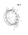
- the sun gear teeth 118 are configured to rotate and drive motion of sync ring 108 in an axial and rotational direction with respect to the centerline axis A, indicated by the double-headed arrow in Fig. 2 .
- a center 115 of planet gear 116 is configured to move along an arcuate path indicated schematically by the arrows in Fig. 3 .
- a circle defined by the arcuate path is concentric with sun gear 117 and the set of sun gear teeth 118.
- sync ring 108 due to the connection of sync ring 108 and vane arms 114, a single point on the surface of sync ring 108 moves in a curvilinear path as sync ring 108 is moved through its incremental range of positive and negative angular rotation about centerline axis A.
- this displacement path is viewed from any plane whose normal intersects centerline axis A, the path of sync ring 108 displacement appears as a simple arc, similar to the arcuate path traveled by center 115 of planet gear 116.
- the radius of this simple arc of travel of planet gear 116 is equal to one half of the sum of the pitch diameters of sun gear 117 and planet gear 116.
- transmission mechanism 110 includes an input shaft 124 extending in a radially outward direction with respect to case 104.
- Input shaft 124 has a first end 125 and a second end 127 and defines an actuator axis therebetween.
- the actuator axis is the same as axis D of the set of sun gear teeth 118 because sun gear 117 is concentric with input shaft 124.
- Sun gear 117 is positioned proximate to first end 125 of input shaft 124 and operatively connects input shaft 124 to planet gear 116.
- Input shaft 124 is configured to rotate sun gear 117 about actuator axis D.
- Input shaft 124 is mounted normal relative to the centerline axis A of sync ring 108.
- transmission mechanism 110 includes a housing 126 that is connected to ring gear segment 122.
- Housing 126 surrounds at least a portion of sun gear 117 and/or a portion of planet gear 116.
- housing 126 is mounted radially outward of sync ring 108 and case 104 and is configured to be stationary with respect to ring gear segment 122 and an axis of sun gear 117 and to case 104.
- Axis D of sun gear 117 is coincident with actuator axis D.
- the diameter of sun gear 117 (and consequently, the diameter of planet gear 116) can be varied such the gear ratio of sun gear 117 to planet gear 116 can be set to any suitable value for a given application.
- the distance between the center of sun gear 117 and center 115 of planet gear 116 for any given application depends on the radius at which planet gear 116 is attached to sync ring 108.
- the diametral pitch of the gear set can be chosen such that there are an integral number of teeth on planet gear 116.
- sun gear 117 will make less than a full turn when the system is operated over the total required range of operation, then a full sun gear, e.g. sun gear 117, is not required and only sun gear teeth 118, e.g. a portion of full sun gear 117, is required to have an integral number of teeth, as will be described below.
- planet gear 116 is connected to sync ring 108 through a spherical joint 128.
- An end surface 129 of housing 126 defines a gear plane E, which extends in and out of the page, as shown in Fig. 4 .
- gear plane E which extends in and out of the page, as shown in Fig. 4 .
- radial line F shown in Fig. 4
- Radial line F is normal to gear plane E while radial line G is not normal to gear plane E due to the rotation of sync ring 108 about centerline axis A.
- spherical joint 128 is configured to allow planet gear 116 remain substantially parallel to gear plane E while allowing sync ring 108 to rotate about and move axially with respect to centerline axis A.
- spherical joint 128 to absorb the misalignment brought about by rotating sync ring 108 about centerline axis A, there can be a displacement of planet gear 116 relative to the gear plane E, i.e. planet gear 116 will move vertically with respect to gear plane E, as oriented in Fig. 4 .
- the thickness of planet gear 116, sun gear 117, and ring gear segment 122 can be configured to allow for this vertical motion.
- a transmission mechanism 210 is similar to transmission mechanism 110, described above.
- a partial sun gear 219 makes less than a full turn when the system is operated over the total required range of operation, therefore a full sun gear, e.g. sun gear 117, is not required.
- a set of sun gear teeth 218 are circumferentially disposed on a periphery of partial sun gear 219, while a portion 230 of partial sun gear 219 remains without sun gear teeth 218.
- transmission mechanisms e.g. transmission mechanisms 110 and 210
- transmission mechanisms 110 and 210 tend to provide an increased mechanical advantage compared to that of a traditional bell-crank mechanism.
- the limitation on input angle means that a maximum mechanical advantage of 3:1 can be achieved.
- This 90 degree limitation on the input angle of a bell-crank mechanism is generally imposed to maintain an approximately linear correlation between the input angle and the output displacement of the bell-crank mechanism. Any other suitable mechanical advantage can be used for a given application without departing from the scope of this disclosure.
- variable vane position is generally measured implicitly by measuring the angular position of an actuator output shaft.
- transmission mechanisms e.g. transmission mechanisms 110 and 210
- the vane position measurement tends to be more accurate than transmission systems having lower mechanical advantage and correspondingly smaller actuator output shaft displacement ranges.
- a bell-crank mechanism in order for a bell-crank mechanism to achieve a similar displacement to that of transmission mechanisms, e.g. transmission mechanisms 110 and 210, a bell-crank mechanism tends to require input from a larger actuator, capable of generating larger actuation forces, than is required for transmission mechanisms.
- larger actuation forces such as those used in traditional bell-crank mechanisms tend to require larger linkage components between the actuator and the bell-crank mechanism than those required for transmission mechanisms, tending to make the actuator system using the bell-crank mechanism heavier than one using transmission mechanisms.
Landscapes
- Engineering & Computer Science (AREA)
- General Engineering & Computer Science (AREA)
- Mechanical Engineering (AREA)
- Retarders (AREA)
Abstract
Description
- The present disclosure relates to transmission mechanisms, and more particularly to transmission mechanisms, such as in synchronization rings for variable vanes in gas turbine engines.
- Traditionally, turbo fan engines for aircraft can include multiple stages of variable vanes to condition and guide airflow through the compressor and/or turbine sections. Variable vanes are configured to be pivoted about their respective vane axis to alter the angle of attack in order to optimize airflow characteristics for various operating conditions.
- Variable vanes can be connected to a synchronization ring (sync ring), each by a respective vane arm connected to the stem of the respective vane. The sync ring can drive each variable vane counter-clockwise and/or clockwise around its respective longitudinal axis in order to adjust vane stage angle for a particular operating condition. Bell-crank style mechanisms are commonly used to convert the linear or rotational force and displacement of an actuator output shaft into an equivalent force and displacement suitable for driving the sync ring over the desired range of angular rotation. Depending on the desired range of angular displacement of the variable vanes, the limitation on input angle for bell-crank style mechanisms can limit the mechanical advantage that can be achieved through the bell-crank mechanism. This can ultimately limit the accuracy of angle of attack for traditional variable vane systems.
- Such conventional methods and systems have generally been considered satisfactory for their intended purpose. However, there is still a need in the art for improved transmission mechanisms. The present disclosure provides a solution for this need.
- A transmission mechanism includes a planet gear, a set of sun gear teeth and a set of ring gear teeth. The planet gear is configurable to be mounted to a synchronization ring (sync ring) for rotation relative to the sync ring about a planet gear axis. The set of sun gear teeth are meshed with teeth of the planet gear. The set of sun gear teeth is configured to rotate and drive motion of the planet gear in a circumferential direction about an axis of the set of sun gear teeth. The set of ring gear teeth are meshed with the teeth of the planet gear. The set of sun gear teeth and the set of ring gear teeth are spaced apart from one another.
- It is contemplated that a center of the planet gear can be configured to move along an arcuate path. A circle defined by the arcuate path can be concentric with the set of sun gear teeth. The transmission mechanism can include an input shaft configured to extend in a radially outward direction with respect to a sync ring. The input shaft can have a first end and a second end and can define an actuator axis therebetween. The set of sun gear teeth can be defined proximate to the first end of the input shaft and can operatively connect the input shaft to the planet gear. The input shaft can be configured to rotate the set of sun gear teeth about the actuator axis. The set of sun gear teeth can be concentric with the input shaft. The input shaft can be configured to be normal to a rotation axis of a sync ring and to be mounted to the sun gear.
- The transmission mechanism can include a housing that can be operatively connected to the set of ring gear teeth. The housing can surround at least a portion of the set of sun gear teeth and/or the planet gear. In addition, the housing can be configured to be disposed radially outward of a sync ring mounted to the planet gear and can be configured to be stationary with respect to the set of ring gear teeth and an axis of the set of sun gear teeth.
- The planet gear can be configured to connect to a sync ring through a spherical joint. An end surface of the housing can define a gear plane. The spherical joint can be configured to allow the planet gear to remain parallel with respect to the gear plane throughout an arc of motion. In addition, the spherical joint can be configured to allow a sync ring to rotate about and move axially with respect to a centerline axis to follow the arc of motion of the planet gear.
- It is also contemplated the set of ring gear teeth can be disposed on a partial ring gear defining a segment of a full ring gear. The set of sun gear teeth can be circumferentially disposed on a periphery of a partial sun gear defining a segment of a full sun gear.
- A variable vane system includes a sync ring defining a centerline axis, a plurality of variable vanes, and a transmission mechanism similar to the transmission mechanism described above. The transmission mechanism is configured to drive motion of sync ring in an axial and rotational direction with respect to the centerline axis. The plurality of variable vanes are operatively connected to the sync ring such that the axial and rotational motion of the sync ring drives the rotation of the variable vanes to adjust the angle of attack of the variable vanes. It is contemplated that the variable vane system can include a plurality of vane arms operatively connecting an end of each variable vane to the sync ring. It is also contemplated that the housing can surround at least a portion of the transmission mechanism.
- These and other features of the systems and methods of the subject disclosure will become more readily apparent to those skilled in the art from the following detailed description of the preferred embodiments taken in conjunction with the drawings.
- So that those skilled in the art to which the subject disclosure appertains will readily understand how to make and use the devices and methods of the subject disclosure without undue experimentation, preferred embodiments thereof will be described in detail herein below by way of example only, and with reference to certain figures, wherein:
-
Fig. 1 is a schematic cross-sectional side elevation view of an exemplary embodiment of a gas turbine engine constructed in accordance with the present disclosure, showing a location of a variable vane system; -
Fig. 2 is a schematic partial perspective view of a portion of the gas turbine engine shown inFig. 1 , showing an engine case and a synchronization ring surrounding the turbine; -
Fig. 3 is a cut-away perspective view of a portion of a variable vane system of the gas turbine engine shown inFig. 1 , showing a synchronization ring, a transmission mechanism, and a vane arm; -
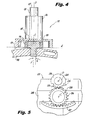
Fig. 4 is a partial cross-sectional view of an exemplary embodiment of the transmission mechanism ofFig. 3 , showing a spherical joint and a planet gear; and -
Fig. 5 is a schematic partial plan view of an exemplary embodiment of a transmission mechanism constructed in accordance with the present disclosure, showing a partial sun gear. - Reference will now be made to the drawings wherein like reference numerals identify similar structural features or aspects of the subject disclosure. For purposes of explanation and illustration, and not limitation, a cross-sectional view of an exemplary embodiment of the gas turbine engine constructed in accordance with the disclosure is shown in
Fig. 1 and is designated generally byreference character 100. Other embodiments of gas turbine engines constructed in accordance with the disclosure, or aspects thereof, are provided inFigs. 2-5 , as will be described. - As shown in
Fig. 1 , avariable vane system 102 includes acase 104 and a plurality ofvariable vanes 106.Variable vane system 102 is disposed in aturbine section 103 ofgas turbine engine 100.Variable vanes 106 are stator vanes and project radially inward fromcase 104.Variable vane system 102 is shown in a highpressure turbine section 105 but could also be applied in a lowpressure turbine section 107. Those skilled in the art will also readily appreciate thatvariable vane system 102 can also be disposed in acompressor section 101 ofgas turbine engine 100, or can be used in any other suitable application. - As shown in
Fig. 2 ,variable vane system 102 includes a synchronization ring 108 (sync ring) disposed radially inward ofcase 104 defining a centerline axis A and atransmission mechanism 110. Whilesync ring 108 is shown and described herein as being disposed radially inward ofcase 104, those skilled in the art will readily appreciate that, depending on the application,sync ring 108 can be disposed radially outward ofcase 104.Variable vanes 106 project radially inward fromcase 104. Thesync ring 108 is operatively connected to thevariable vanes 106 such that the axial and rotational motion ofsync ring 108 drives the rotation ofvariable vanes 106 about a vane axis B to adjust their angle of attack. The rotation ofsync ring 108 about centerline axis A is indicated schematically by a double-headed arrow. The rotation ofvariable vanes 106 about vane axis B is also indicated schematically by a separate double-headed arrow.Variable vane system 102 includes a plurality ofvane arms 114 operatively connecting a vane stem of eachvariable vane 106 to syncring 108. Those skilled in the art will readily appreciate that whilevariable vane system 102 is shown with twotransmission mechanisms 110, any suitable number of transmission mechanisms may be used. - With reference now to
Fig. 3 ,transmission mechanism 110 includes aplanet gear 116, a set ofsun gear teeth 118 and a set of ring gear teeth 120.Planet gear 116 is mounted to syncring 108 for rotation relative to syncring 108 about a planet gear axisC. Transmission mechanism 110 includes aring gear segment 122. The set of ring gear teeth 120 is disposed on a partial ring gear 121 definingring gear segment 122.Transmission mechanism 110 converts the rotational motion of aninput shaft 124, described below, into curvilinear motion for drivingsync ring 108. - With continued reference to
Fig. 3 ,transmission mechanism 110 includes afull sun gear 117. The set ofsun gear teeth 118 is circumferentially disposed on a periphery of apartial sun gear 119 defining a segment offull sun gear 117. Thesun gear teeth 118 mesh withteeth 112 ofplanet gear 116. Thesun gear teeth 118 are configured to rotate and drive the motion ofplanet gear 116 in a circumferential direction, about an axis D of the set ofsun gear teeth 118. The ring gear teeth 120 are meshed withteeth 112 ofplanet gear 116. Thesun gear teeth 118 and the ring gear teeth 120 are spaced apart from one another, so as not to interfere with one another. Thesun gear teeth 118 are configured to rotate and drive motion ofsync ring 108 in an axial and rotational direction with respect to the centerline axis A, indicated by the double-headed arrow inFig. 2 . Acenter 115 ofplanet gear 116 is configured to move along an arcuate path indicated schematically by the arrows inFig. 3 . A circle defined by the arcuate path is concentric withsun gear 117 and the set ofsun gear teeth 118. - With continued reference to
Fig. 3 , those skilled in the art will readily appreciate that due to the connection ofsync ring 108 andvane arms 114, a single point on the surface ofsync ring 108 moves in a curvilinear path assync ring 108 is moved through its incremental range of positive and negative angular rotation about centerline axis A. When this displacement path is viewed from any plane whose normal intersects centerline axis A, the path ofsync ring 108 displacement appears as a simple arc, similar to the arcuate path traveled bycenter 115 ofplanet gear 116. Those skilled in the art will readily appreciate that the radius of this simple arc of travel ofplanet gear 116 is equal to one half of the sum of the pitch diameters ofsun gear 117 andplanet gear 116. By establishing the pitch diameters ofsun gear 117 andplanet gear 116 such that the distance between their centers exactly matches the radius of the arc of displacement ofsync ring 108,planet gear 116 can drivesync ring 108 by attachingsync ring 108 to a bore ofplanet gear 116. - As shown in
Figs. 2 and3 ,transmission mechanism 110 includes aninput shaft 124 extending in a radially outward direction with respect tocase 104.Input shaft 124 has afirst end 125 and asecond end 127 and defines an actuator axis therebetween. The actuator axis is the same as axis D of the set ofsun gear teeth 118 becausesun gear 117 is concentric withinput shaft 124.Sun gear 117 is positioned proximate tofirst end 125 ofinput shaft 124 and operatively connectsinput shaft 124 toplanet gear 116.Input shaft 124 is configured to rotatesun gear 117 about actuator axisD. Input shaft 124 is mounted normal relative to the centerline axis A ofsync ring 108. - With continued reference to
Figs. 2 and3 ,transmission mechanism 110 includes ahousing 126 that is connected to ringgear segment 122.Housing 126 surrounds at least a portion ofsun gear 117 and/or a portion ofplanet gear 116. In addition,housing 126 is mounted radially outward ofsync ring 108 andcase 104 and is configured to be stationary with respect toring gear segment 122 and an axis ofsun gear 117 and tocase 104. Axis D ofsun gear 117 is coincident with actuator axis D. - Those skilled in the art will readily appreciate that the diameter of sun gear 117 (and consequently, the diameter of planet gear 116) can be varied such the gear ratio of
sun gear 117 toplanet gear 116 can be set to any suitable value for a given application. Those skilled in the art will also readily appreciate that the distance between the center ofsun gear 117 andcenter 115 ofplanet gear 116 for any given application depends on the radius at whichplanet gear 116 is attached to syncring 108. - Those skilled in the art will also readily appreciate that the diametral pitch of the gear set can be chosen such that there are an integral number of teeth on
planet gear 116. In addition, those skilled in the art will readily appreciate that it is not necessary that a full ring gear have an integral number of teeth, because onlyring gear segment 122 is required. Likewise, it is contemplated that if the gear ratio is such thatsun gear 117 will make less than a full turn when the system is operated over the total required range of operation, then a full sun gear,e.g. sun gear 117, is not required and onlysun gear teeth 118, e.g. a portion offull sun gear 117, is required to have an integral number of teeth, as will be described below. Those skilled in the art will readily appreciate that the mechanical advantage of the system can be easily modified by changing the relative diameters ofsun gear 117 andplanet gear 116. This allows the total operating range ofinput shaft 124 to be independently optimized for either a linear actuator or a rotary actuator. - As shown in
Fig. 4 ,planet gear 116 is connected to syncring 108 through a spherical joint 128. Anend surface 129 ofhousing 126 defines a gear plane E, which extends in and out of the page, as shown inFig. 4 . Those skilled in the art will readily appreciate thatsync ring 108 and spherical joint 128 are rotated away from its initial starting position designated by radial line F, shown inFig. 4 , the middle of its angular range of operation, to a radial line G. Radial line F is normal to gear plane E while radial line G is not normal to gear plane E due to the rotation ofsync ring 108 about centerline axis A. - In order to accommodate for this misalignment, spherical joint 128 is configured to allow
planet gear 116 remain substantially parallel to gear plane E while allowingsync ring 108 to rotate about and move axially with respect to centerline axis A. Those skilled in the art will readily appreciate that even with the incorporation of spherical joint 128 to absorb the misalignment brought about by rotatingsync ring 108 about centerline axis A, there can be a displacement ofplanet gear 116 relative to the gear plane E, i.e.planet gear 116 will move vertically with respect to gear plane E, as oriented inFig. 4 . The thickness ofplanet gear 116,sun gear 117, andring gear segment 122 can be configured to allow for this vertical motion. - With reference now to
Fig. 5 , atransmission mechanism 210 is similar totransmission mechanism 110, described above. Intransmission mechanism 210, apartial sun gear 219 makes less than a full turn when the system is operated over the total required range of operation, therefore a full sun gear,e.g. sun gear 117, is not required. A set ofsun gear teeth 218 are circumferentially disposed on a periphery ofpartial sun gear 219, while aportion 230 ofpartial sun gear 219 remains withoutsun gear teeth 218. - Those skilled in the art will readily appreciate that transmission mechanisms,
e.g. transmission mechanisms - Those skilled in the art will also readily appreciate that variable vane position is generally measured implicitly by measuring the angular position of an actuator output shaft. By virtue of the increased mechanical advantage of transmission mechanisms,
e.g. transmission mechanisms - In addition, those skilled in the art will readily appreciate that in order for a bell-crank mechanism to achieve a similar displacement to that of transmission mechanisms,
e.g. transmission mechanisms - Those skilled in the art will readily appreciate that for a given input shaft rotation angle, the arrangement described herein has the potential to provide a greater degree of mechanical advantage than a simple bellcrank arrangement and would therefore reduce actuator torque requirements and actuation linkage loads, potentially reducing actuation system weight while improving accuracy.
- The methods and systems of the present disclosure, as described above and shown in the drawings, provide for transmission mechanisms and variable vane systems with superior properties including potentially improved mechanical advantage, potentially increased accuracy and potentially reduced weight. While the apparatus and methods of the subject disclosure have been shown and described with reference to preferred embodiments, those skilled in the art will readily appreciate that changes and/or modifications may be made thereto without departing from the scope of the subject disclosure as set out in the claims.
- Further features of the invention are given below in the following numbered clauses:
- 1. A transmission mechanism comprising:
- a planet gear configured to be mounted to a synchronization ring for rotation relative to the synchronization ring about a planet gear axis;
- a set of sun gear teeth meshed with teeth of the planet gear, wherein the set of sun gear teeth is configured to rotate and drive motion of the planet gear in a circumferential direction about an axis of the set of sun gear teeth; and
- a set of ring gear teeth meshed with the teeth of the planet gear, wherein the set of sun gear teeth and the set of ring gear teeth are spaced apart from one another.
- 2. A transmission mechanism as recited in
clause 1, wherein a center of the planet gear is configured to move along an arcuate path, wherein a circle defined by the arcuate path is concentric with the set of sun gear teeth. - 3. A transmission mechanism as recited in
clause 1, further comprising an input shaft configured to extend in a radially outward direction with respect to a synchronization ring, the input shaft having a first end and a second end, defining an actuator axis therebetween, wherein the set of sun gear teeth is defined proximate to the first end of the input shaft operatively connecting the input shaft to the planet gear. - 4. A transmission mechanism as recited in
clause 3, wherein the input shaft is configured to rotate the set of sun gear teeth about the actuator axis. - 5. A transmission mechanism as recited in
clause 3, wherein the set of sun gear teeth is concentric with the input shaft. - 6. A transmission mechanism as recited in
clause 3, wherein the input shaft is configured to be mounted to the sun gear and to be normal to a centerline axis of a synchronization ring. - 7. A transmission mechanism as recited in
clause 1, further comprising a housing operatively connected to the set of ring gear teeth and surrounding at least a portion of at least one of the set of sun gear teeth and the planet gear, wherein the housing is configured to be disposed radially outward of a synchronization ring and configured to be stationary with respect to the set of ring gear teeth and an axis of the set of sun gear teeth. - 8. A transmission mechanism as recited in
clause 1, wherein the planet gear is configured to connect to a synchronization ring through a spherical joint, wherein an end surface of a housing defines a gear plane, wherein the spherical joint is configured to allow the planet gear to remain parallel with respect to the gear plane throughout an arc of motion, and wherein the spherical joint is configured to allow a synchronization ring to rotate about and move axially with respect to a centerline axis to follow an arc of motion of the planet gear. - 9. A transmission mechanism as recited in
clause 1, wherein the set of ring gear teeth is disposed on a partial ring gear defining a segment of a full ring gear. - 10. A transmission mechanism as recited in
clause 1, wherein the set of sun gear teeth is circumferentially disposed on a periphery of a partial sun gear defining a segment of a full sun gear. - 11. A variable vane system, comprising:
- a synchronization ring defining a centerline axis;
- a transmission mechanism including:
- a planet gear mounted radially outward of the synchronization ring for rotation relative to the synchronization ring about a planet gear axis;
- a set of sun gear teeth meshed with teeth of the planet gear, wherein the set of sun gear teeth is configured to rotate and drive motion of the planet gear in a circumferential direction about an axis of the set of sun gear teeth, actuating the synchronization ring for axial and rotational motion with respect to the centerline axis; and
- a set of ring gear teeth meshed with the teeth of the planet gear, wherein the set of sun gear teeth and the set of ring gear teeth are spaced apart from one another; and
- a plurality of variable vanes operatively connected to the synchronization ring such that the axial and rotational motion of the synchronization ring drives the rotation of the variable vanes to adjust the angle of attack of the variable vanes.
- 12. A variable vane system as recited in clause 11, wherein a center of the planet gear is configured to move along an arcuate path, wherein a circle defined by the arcuate path is concentric with the set of sun gear teeth.
- 13. A variable vane system as recited in clause 11, further comprising a plurality of vane arms operatively connecting an end of each variable vane to the synchronization ring.
- 14. A variable vane system as recited in clause 11, further comprising an input shaft extending in a radially outward direction with respect to the synchronization ring, the input shaft having a first end and a second end, defining an actuator axis therebetween, wherein the set of sun gear teeth is defined proximate to the first end of the input shaft operatively connecting the input shaft to the planet gear.
- 15. A variable vane system as recited in clause 14, wherein the input shaft is configured to rotate the set of sun gear teeth about the actuator axis.
- 16. A variable vane system as recited in clause 14, wherein the input shaft is normal to the centerline axis of the synchronization ring.
- 17. A variable vane system as recited in clause 11, further comprising a housing disposed radially outward of the synchronization ring operatively connected to the set of ring gear teeth and surrounding at least a portion of the transmission mechanism, wherein the housing is configured to be stationary with respect to the set of ring gear teeth and an axis of the set of sun gear teeth.
- 18. A variable vane system as recited in clause 11, wherein the planet gear is connected to the synchronization ring through a spherical joint, wherein an end surface of a housing defines a gear plane, wherein the spherical joint is configured to allow the planet gear to remain parallel with respect to the gear plane throughout an arc of motion, and wherein the spherical joint is configured to allow a synchronization ring to rotate about and move axially with respect to the centerline axis to follow an arc of motion of the planet gear.
- 19. A variable vane system as recited in clause 11, wherein the set of ring gear teeth is disposed on a partial ring gear defining a segment of a full ring gear.
- 20. A variable vane system as recited in clause 11, wherein the set of sun gear teeth is circumferentially disposed on a periphery of a partial sun gear defining a segment of a full sun gear.
Claims (15)
- A transmission mechanism (110; 210) comprising:a planet gear (116; 216) configured to be mounted to a synchronization ring (108) for rotation relative to the synchronization ring about a planet gear axis (C);a set of sun gear teeth (118; 218) meshed with teeth (112) of the planet gear, wherein the set of sun gear teeth is configured to rotate and drive motion of the planet gear in a circumferential direction about an axis (D) of the set of sun gear teeth; anda set of ring gear teeth (120) meshed with the teeth of the planet gear, wherein the set of sun gear teeth and the set of ring gear teeth are spaced apart from one another.
- A transmission mechanism as recited in claim 1, wherein a center (115) of the planet gear is configured to move along an arcuate path, wherein a circle defined by the arcuate path is concentric with the set of sun gear teeth.
- A transmission mechanism as recited in claims 1 or 2, further comprising an input shaft (124) configured to extend in a radially outward direction with respect to the synchronization ring, the input shaft having a first end (125) and a second end (127), defining an actuator axis (D) therebetween, wherein the set of sun gear teeth is defined proximate to the first end of the input shaft operatively connecting the input shaft to the planet gear.
- A transmission mechanism as recited in claim 3, wherein the input shaft is configured to rotate the set of sun gear teeth about the actuator axis.
- A transmission mechanism as recited in claims 3 or 4, wherein the set of sun gear teeth is concentric with the input shaft.
- A transmission mechanism as recited in claim 3, wherein the input shaft is configured to be mounted to the sun gear and to be normal to a centerline axis (A) of the synchronization ring.
- A transmission mechanism as recited in any preceding claim, further comprising a housing (126) operatively connected to the set of ring gear teeth and surrounding at least a portion of at least one of the set of sun gear teeth and the planet gear, wherein the housing is configured to be disposed radially outward of the synchronization ring and configured to be stationary with respect to the set of ring gear teeth and an axis (D) of the set of sun gear teeth.
- A transmission mechanism as recited in any preceding claim, wherein the planet gear is configured to connect to the synchronization ring through a spherical joint (128; 228), wherein an end surface (129) of a housing (126) defines a gear plane (E), wherein the spherical joint is configured to allow the planet gear to remain parallel with respect to the gear plane throughout an arc of motion, and wherein the spherical joint is configured to allow the synchronization ring to rotate about and move axially with respect to a centerline axis (A) to follow an arc of motion of the planet gear; and/or
wherein the set of ring gear teeth is disposed on a partial ring gear (121) defining a segment (122; 222) of a full ring gear; and/or
wherein the set of sun gear teeth is circumferentially disposed on a periphery of a partial sun gear (119; 219) defining a segment of a full sun gear (117). - A variable vane system, comprising:the transmission mechanism as recited in claim 1, wherein:the synchronization ring defines a centerline axis (A);the planet gear is mounted radially outward of the synchronization ring; andthe set of sun gear teeth actuates the synchronization ring for axial and rotationalmotion with respect to the centerline axis; anda plurality of variable vanes (106) operatively connected to the synchronization ring such that the axial and rotational motion of the synchronization ring drives the rotation of the variable vanes to adjust the angle of attack of the variable vanes.
- A variable vane system as recited in claim 9, wherein a center (115) of the planet gear is configured to move along an arcuate path, wherein a circle defined by the arcuate path is concentric with the set of sun gear teeth.
- A variable vane system as recited in claims 9 or 10, further comprising a plurality of vane arms (114) operatively connecting an end of each variable vane to the synchronization ring.
- A variable vane system as recited in any of claims 9 to 11, further comprising an input shaft (124) extending in a radially outward direction with respect to the synchronization ring, the input shaft having a first end (125) and a second end (127), defining an actuator axis (D) therebetween, wherein the set of sun gear teeth is defined proximate to the first end of the input shaft operatively connecting the input shaft to the planet gear.
- A variable vane system as recited in claim 12, wherein the input shaft is configured to rotate the set of sun gear teeth about the actuator axis; and/or
wherein the input shaft is normal to the centerline axis of the synchronization ring. - A variable vane system as recited in any of claims 9 to 13, further comprising a housing (126) disposed radially outward of the synchronization ring operatively connected to the set of ring gear teeth and surrounding at least a portion of the transmission mechanism, wherein the housing is configured to be stationary with respect to the set of ring gear teeth and an axis (D) of the set of sun gear teeth.
- A variable vane system as recited in any of claims 9 to 14, wherein the planet gear is connected to the synchronization ring through a spherical joint (128; 228), wherein an end surface (129) of a housing (126) defines a gear plane (E), wherein the spherical joint is configured to allow the planet gear to remain parallel with respect to the gear plane throughout an arc of motion, and wherein the spherical joint is configured to allow the synchronization ring to rotate about and move axially with respect to the centerline axis to follow an arc of motion of the planet gear; and/or
wherein the set of ring gear teeth is disposed on a partial ring gear (121) defining a segment (122; 222) of a full ring gear; and/or
wherein the set of sun gear teeth is circumferentially disposed on a periphery of a partial sun gear (119; 219) defining a segment of a full sun gear (117).
Priority Applications (2)
| Application Number | Priority Date | Filing Date | Title |
|---|---|---|---|
| EP17185912.7A EP3266988B1 (en) | 2014-02-21 | 2015-02-23 | Variable vane synchronization ring transmission mechanisms |
| EP19168258.2A EP3530886B1 (en) | 2014-02-21 | 2015-02-23 | Variable vane synchronization ring transmission mechanisms |
Applications Claiming Priority (1)
| Application Number | Priority Date | Filing Date | Title |
|---|---|---|---|
| US201461942770P | 2014-02-21 | 2014-02-21 |
Related Child Applications (2)
| Application Number | Title | Priority Date | Filing Date |
|---|---|---|---|
| EP19168258.2A Division EP3530886B1 (en) | 2014-02-21 | 2015-02-23 | Variable vane synchronization ring transmission mechanisms |
| EP17185912.7A Division EP3266988B1 (en) | 2014-02-21 | 2015-02-23 | Variable vane synchronization ring transmission mechanisms |
Publications (2)
| Publication Number | Publication Date |
|---|---|
| EP2910740A1 true EP2910740A1 (en) | 2015-08-26 |
| EP2910740B1 EP2910740B1 (en) | 2017-08-23 |
Family
ID=52577684
Family Applications (3)
| Application Number | Title | Priority Date | Filing Date |
|---|---|---|---|
| EP15156166.9A Active EP2910740B1 (en) | 2014-02-21 | 2015-02-23 | Variable vane sychronization ring transmission mechanisms |
| EP17185912.7A Active EP3266988B1 (en) | 2014-02-21 | 2015-02-23 | Variable vane synchronization ring transmission mechanisms |
| EP19168258.2A Active EP3530886B1 (en) | 2014-02-21 | 2015-02-23 | Variable vane synchronization ring transmission mechanisms |
Family Applications After (2)
| Application Number | Title | Priority Date | Filing Date |
|---|---|---|---|
| EP17185912.7A Active EP3266988B1 (en) | 2014-02-21 | 2015-02-23 | Variable vane synchronization ring transmission mechanisms |
| EP19168258.2A Active EP3530886B1 (en) | 2014-02-21 | 2015-02-23 | Variable vane synchronization ring transmission mechanisms |
Country Status (2)
| Country | Link |
|---|---|
| US (1) | US10012102B2 (en) |
| EP (3) | EP2910740B1 (en) |
Cited By (2)
| Publication number | Priority date | Publication date | Assignee | Title |
|---|---|---|---|---|
| GB2589098A (en) * | 2019-11-19 | 2021-05-26 | Rolls Royce Plc | Variable vane mechanism |
| US20220403920A1 (en) * | 2021-06-18 | 2022-12-22 | Schlage Lock Company Llc | Rotation converter |
Families Citing this family (6)
| Publication number | Priority date | Publication date | Assignee | Title |
|---|---|---|---|---|
| US10358934B2 (en) * | 2016-04-11 | 2019-07-23 | United Technologies Corporation | Method and apparatus for adjusting variable vanes |
| GB201613029D0 (en) * | 2016-07-28 | 2016-09-14 | Rolls Royce Plc | A sun gear drive arrangement |
| US10557371B2 (en) | 2017-07-14 | 2020-02-11 | United Technologies Corporation | Gas turbine engine variable vane end wall insert |
| CN108179969B (en) * | 2017-12-18 | 2019-12-13 | 绍兴卓亚装饰材料有限公司 | Curtain guide rail |
| US11480111B2 (en) * | 2019-05-15 | 2022-10-25 | Honeywell International Inc. | Variable area turbine nozzle and method |
| CN113202621B (en) * | 2021-06-14 | 2022-04-01 | 中国航发沈阳发动机研究所 | Stator blade rotation angle adjusting mechanism |
Citations (2)
| Publication number | Priority date | Publication date | Assignee | Title |
|---|---|---|---|---|
| EP2626521A1 (en) * | 2012-02-13 | 2013-08-14 | Rolls-Royce plc | A unison ring gear assembly for a gas turbine |
| WO2013177785A1 (en) * | 2012-05-31 | 2013-12-05 | Robert Bosch Gmbh | Planetary gear transmission and electric vehicle |
Family Cites Families (8)
| Publication number | Priority date | Publication date | Assignee | Title |
|---|---|---|---|---|
| US5205712A (en) * | 1991-05-13 | 1993-04-27 | Allied-Signal Inc. | Variable pitch fan gas turbine engine |
| JP3646966B2 (en) | 1998-02-03 | 2005-05-11 | 富士重工業株式会社 | Hybrid car |
| JP2001043940A (en) | 1999-07-30 | 2001-02-16 | Fci Japan Kk | Electric connector |
| CN2661479Y (en) | 2003-04-24 | 2004-12-08 | 北京理工大学 | Single planet row two-gear transmission case for electric automobile |
| CN2875938Y (en) | 2005-11-25 | 2007-03-07 | 天津清源电动车辆有限责任公司 | Full automatic two axle uncontinuous speed change device of electrically driven vehicle |
| GB2465997A (en) | 2008-12-05 | 2010-06-09 | Gm Global Tech Operations Inc | A dual clutch transmission with Ravigneaux type planetary gearsets |
| CN101544181B (en) | 2009-05-15 | 2011-04-20 | 新奥科技发展有限公司 | Power assembly system |
| CN102182801A (en) | 2011-05-19 | 2011-09-14 | 苏州安远新能源动力有限公司 | Two-gear automatic transmission of planet wheel type electric automobile |
-
2015
- 2015-02-16 US US14/623,296 patent/US10012102B2/en active Active
- 2015-02-23 EP EP15156166.9A patent/EP2910740B1/en active Active
- 2015-02-23 EP EP17185912.7A patent/EP3266988B1/en active Active
- 2015-02-23 EP EP19168258.2A patent/EP3530886B1/en active Active
Patent Citations (2)
| Publication number | Priority date | Publication date | Assignee | Title |
|---|---|---|---|---|
| EP2626521A1 (en) * | 2012-02-13 | 2013-08-14 | Rolls-Royce plc | A unison ring gear assembly for a gas turbine |
| WO2013177785A1 (en) * | 2012-05-31 | 2013-12-05 | Robert Bosch Gmbh | Planetary gear transmission and electric vehicle |
Cited By (3)
| Publication number | Priority date | Publication date | Assignee | Title |
|---|---|---|---|---|
| GB2589098A (en) * | 2019-11-19 | 2021-05-26 | Rolls Royce Plc | Variable vane mechanism |
| US20220403920A1 (en) * | 2021-06-18 | 2022-12-22 | Schlage Lock Company Llc | Rotation converter |
| US12006734B2 (en) * | 2021-06-18 | 2024-06-11 | Schlage Lock Company Llc | Rotation converter |
Also Published As
| Publication number | Publication date |
|---|---|
| EP3266988B1 (en) | 2019-04-10 |
| EP2910740B1 (en) | 2017-08-23 |
| US10012102B2 (en) | 2018-07-03 |
| EP3530886B1 (en) | 2020-07-22 |
| US20150354400A1 (en) | 2015-12-10 |
| EP3530886A1 (en) | 2019-08-28 |
| EP3266988A1 (en) | 2018-01-10 |
Similar Documents
| Publication | Publication Date | Title |
|---|---|---|
| EP3266988B1 (en) | Variable vane synchronization ring transmission mechanisms | |
| US8435000B2 (en) | Variable vane actuation system | |
| US9797265B2 (en) | Stator vane adjusting device of a gas turbine | |
| US10577078B2 (en) | Systems and methods for electronic measurement of propeller blade angle | |
| US10669882B2 (en) | Variable stator blade operating device | |
| US10837307B2 (en) | System of variable stator vanes for a turbine engine | |
| US9617922B2 (en) | Jet engine actuation system | |
| US8905887B2 (en) | Unison ring gear assembly | |
| US10279889B2 (en) | Device for supplying hydraulic fluid to a ram and mechanism for controlling the pitch of the blades of a turbine engine propeller comprising the ram | |
| US20160032740A1 (en) | Variable-pitch rotor with remote counterweights | |
| EP3266981A1 (en) | Gas turbine engine having a turbine rotor with torque transfer and balance features | |
| US10774672B2 (en) | Rotary actuator for variable vane adjustment system | |
| US20180017080A1 (en) | Variable stator vane mechanism | |
| CN103291383B (en) | Gas-compressor multistage stationary-blade regulating mechanism allowing gear transmission | |
| US10766603B2 (en) | Pitch-change system equipped with means for adjusting blade pitch and corresponding turbine engine | |
| JP2017100701A (en) | Propeller pitch control system and method | |
| JP6078103B2 (en) | Variable pitch rotor with remote counterweight | |
| US10330021B2 (en) | System for controlling variable-pitch vanes for a turbine engine | |
| US11359511B2 (en) | Pivot for a sliding bearing | |
| US20200040759A1 (en) | Variable Vane Actuation System for a Turbo Machine | |
| CN109844371B (en) | Mechanism for driving a blade-orientation regulating body and aircraft turbomachine comprising such a mechanism | |
| US9695703B2 (en) | Fan having a variable setting by means of differential rotation of the fan disks | |
| RU2674227C1 (en) | Mechanism of regulation of paddles of the guide device of the stator multistage compressor of a gas turbine engine |
Legal Events
| Date | Code | Title | Description |
|---|---|---|---|
| PUAI | Public reference made under article 153(3) epc to a published international application that has entered the european phase |
Free format text: ORIGINAL CODE: 0009012 |
|
| AK | Designated contracting states |
Kind code of ref document: A1 Designated state(s): AL AT BE BG CH CY CZ DE DK EE ES FI FR GB GR HR HU IE IS IT LI LT LU LV MC MK MT NL NO PL PT RO RS SE SI SK SM TR |
|
| AX | Request for extension of the european patent |
Extension state: BA ME |
|
| 17P | Request for examination filed |
Effective date: 20160226 |
|
| RBV | Designated contracting states (corrected) |
Designated state(s): AL AT BE BG CH CY CZ DE DK EE ES FI FR GB GR HR HU IE IS IT LI LT LU LV MC MK MT NL NO PL PT RO RS SE SI SK SM TR |
|
| RIC1 | Information provided on ipc code assigned before grant |
Ipc: F01D 17/16 20060101AFI20160627BHEP Ipc: F16H 19/00 20060101ALI20160627BHEP Ipc: F16H 1/28 20060101ALI20160627BHEP |
|
| GRAP | Despatch of communication of intention to grant a patent |
Free format text: ORIGINAL CODE: EPIDOSNIGR1 |
|
| INTG | Intention to grant announced |
Effective date: 20160919 |
|
| RAP1 | Party data changed (applicant data changed or rights of an application transferred) |
Owner name: UNITED TECHNOLOGIES CORPORATION |
|
| STAA | Information on the status of an ep patent application or granted ep patent |
Free format text: STATUS: GRANT OF PATENT IS INTENDED |
|
| GRAS | Grant fee paid |
Free format text: ORIGINAL CODE: EPIDOSNIGR3 |
|
| GRAJ | Information related to disapproval of communication of intention to grant by the applicant or resumption of examination proceedings by the epo deleted |
Free format text: ORIGINAL CODE: EPIDOSDIGR1 |
|
| GRAL | Information related to payment of fee for publishing/printing deleted |
Free format text: ORIGINAL CODE: EPIDOSDIGR3 |
|
| STAA | Information on the status of an ep patent application or granted ep patent |
Free format text: STATUS: REQUEST FOR EXAMINATION WAS MADE |
|
| GRAP | Despatch of communication of intention to grant a patent |
Free format text: ORIGINAL CODE: EPIDOSNIGR1 |
|
| STAA | Information on the status of an ep patent application or granted ep patent |
Free format text: STATUS: GRANT OF PATENT IS INTENDED |
|
| INTC | Intention to grant announced (deleted) | ||
| INTG | Intention to grant announced |
Effective date: 20170306 |
|
| GRAA | (expected) grant |
Free format text: ORIGINAL CODE: 0009210 |
|
| STAA | Information on the status of an ep patent application or granted ep patent |
Free format text: STATUS: THE PATENT HAS BEEN GRANTED |
|
| AK | Designated contracting states |
Kind code of ref document: B1 Designated state(s): AL AT BE BG CH CY CZ DE DK EE ES FI FR GB GR HR HU IE IS IT LI LT LU LV MC MK MT NL NO PL PT RO RS SE SI SK SM TR |
|
| REG | Reference to a national code |
Ref country code: GB Ref legal event code: FG4D |
|
| REG | Reference to a national code |
Ref country code: CH Ref legal event code: EP |
|
| REG | Reference to a national code |
Ref country code: AT Ref legal event code: REF Ref document number: 921580 Country of ref document: AT Kind code of ref document: T Effective date: 20170915 |
|
| REG | Reference to a national code |
Ref country code: IE Ref legal event code: FG4D |
|
| REG | Reference to a national code |
Ref country code: DE Ref legal event code: R096 Ref document number: 602015004199 Country of ref document: DE |
|
| REG | Reference to a national code |
Ref country code: NL Ref legal event code: MP Effective date: 20170823 |
|
| REG | Reference to a national code |
Ref country code: LT Ref legal event code: MG4D |
|
| REG | Reference to a national code |
Ref country code: AT Ref legal event code: MK05 Ref document number: 921580 Country of ref document: AT Kind code of ref document: T Effective date: 20170823 |
|
| REG | Reference to a national code |
Ref country code: FR Ref legal event code: PLFP Year of fee payment: 4 |
|
| PG25 | Lapsed in a contracting state [announced via postgrant information from national office to epo] |
Ref country code: NO Free format text: LAPSE BECAUSE OF FAILURE TO SUBMIT A TRANSLATION OF THE DESCRIPTION OR TO PAY THE FEE WITHIN THE PRESCRIBED TIME-LIMIT Effective date: 20171123 Ref country code: LT Free format text: LAPSE BECAUSE OF FAILURE TO SUBMIT A TRANSLATION OF THE DESCRIPTION OR TO PAY THE FEE WITHIN THE PRESCRIBED TIME-LIMIT Effective date: 20170823 Ref country code: SE Free format text: LAPSE BECAUSE OF FAILURE TO SUBMIT A TRANSLATION OF THE DESCRIPTION OR TO PAY THE FEE WITHIN THE PRESCRIBED TIME-LIMIT Effective date: 20170823 Ref country code: FI Free format text: LAPSE BECAUSE OF FAILURE TO SUBMIT A TRANSLATION OF THE DESCRIPTION OR TO PAY THE FEE WITHIN THE PRESCRIBED TIME-LIMIT Effective date: 20170823 Ref country code: AT Free format text: LAPSE BECAUSE OF FAILURE TO SUBMIT A TRANSLATION OF THE DESCRIPTION OR TO PAY THE FEE WITHIN THE PRESCRIBED TIME-LIMIT Effective date: 20170823 Ref country code: NL Free format text: LAPSE BECAUSE OF FAILURE TO SUBMIT A TRANSLATION OF THE DESCRIPTION OR TO PAY THE FEE WITHIN THE PRESCRIBED TIME-LIMIT Effective date: 20170823 Ref country code: HR Free format text: LAPSE BECAUSE OF FAILURE TO SUBMIT A TRANSLATION OF THE DESCRIPTION OR TO PAY THE FEE WITHIN THE PRESCRIBED TIME-LIMIT Effective date: 20170823 |
|
| PG25 | Lapsed in a contracting state [announced via postgrant information from national office to epo] |
Ref country code: BG Free format text: LAPSE BECAUSE OF FAILURE TO SUBMIT A TRANSLATION OF THE DESCRIPTION OR TO PAY THE FEE WITHIN THE PRESCRIBED TIME-LIMIT Effective date: 20171123 Ref country code: ES Free format text: LAPSE BECAUSE OF FAILURE TO SUBMIT A TRANSLATION OF THE DESCRIPTION OR TO PAY THE FEE WITHIN THE PRESCRIBED TIME-LIMIT Effective date: 20170823 Ref country code: IS Free format text: LAPSE BECAUSE OF FAILURE TO SUBMIT A TRANSLATION OF THE DESCRIPTION OR TO PAY THE FEE WITHIN THE PRESCRIBED TIME-LIMIT Effective date: 20171223 Ref country code: GR Free format text: LAPSE BECAUSE OF FAILURE TO SUBMIT A TRANSLATION OF THE DESCRIPTION OR TO PAY THE FEE WITHIN THE PRESCRIBED TIME-LIMIT Effective date: 20171124 Ref country code: PL Free format text: LAPSE BECAUSE OF FAILURE TO SUBMIT A TRANSLATION OF THE DESCRIPTION OR TO PAY THE FEE WITHIN THE PRESCRIBED TIME-LIMIT Effective date: 20170823 Ref country code: RS Free format text: LAPSE BECAUSE OF FAILURE TO SUBMIT A TRANSLATION OF THE DESCRIPTION OR TO PAY THE FEE WITHIN THE PRESCRIBED TIME-LIMIT Effective date: 20170823 Ref country code: LV Free format text: LAPSE BECAUSE OF FAILURE TO SUBMIT A TRANSLATION OF THE DESCRIPTION OR TO PAY THE FEE WITHIN THE PRESCRIBED TIME-LIMIT Effective date: 20170823 |
|
| PG25 | Lapsed in a contracting state [announced via postgrant information from national office to epo] |
Ref country code: RO Free format text: LAPSE BECAUSE OF FAILURE TO SUBMIT A TRANSLATION OF THE DESCRIPTION OR TO PAY THE FEE WITHIN THE PRESCRIBED TIME-LIMIT Effective date: 20170823 Ref country code: CZ Free format text: LAPSE BECAUSE OF FAILURE TO SUBMIT A TRANSLATION OF THE DESCRIPTION OR TO PAY THE FEE WITHIN THE PRESCRIBED TIME-LIMIT Effective date: 20170823 Ref country code: DK Free format text: LAPSE BECAUSE OF FAILURE TO SUBMIT A TRANSLATION OF THE DESCRIPTION OR TO PAY THE FEE WITHIN THE PRESCRIBED TIME-LIMIT Effective date: 20170823 |
|
| REG | Reference to a national code |
Ref country code: DE Ref legal event code: R097 Ref document number: 602015004199 Country of ref document: DE |
|
| PG25 | Lapsed in a contracting state [announced via postgrant information from national office to epo] |
Ref country code: IT Free format text: LAPSE BECAUSE OF FAILURE TO SUBMIT A TRANSLATION OF THE DESCRIPTION OR TO PAY THE FEE WITHIN THE PRESCRIBED TIME-LIMIT Effective date: 20170823 Ref country code: EE Free format text: LAPSE BECAUSE OF FAILURE TO SUBMIT A TRANSLATION OF THE DESCRIPTION OR TO PAY THE FEE WITHIN THE PRESCRIBED TIME-LIMIT Effective date: 20170823 Ref country code: SK Free format text: LAPSE BECAUSE OF FAILURE TO SUBMIT A TRANSLATION OF THE DESCRIPTION OR TO PAY THE FEE WITHIN THE PRESCRIBED TIME-LIMIT Effective date: 20170823 Ref country code: SM Free format text: LAPSE BECAUSE OF FAILURE TO SUBMIT A TRANSLATION OF THE DESCRIPTION OR TO PAY THE FEE WITHIN THE PRESCRIBED TIME-LIMIT Effective date: 20170823 |
|
| PLBE | No opposition filed within time limit |
Free format text: ORIGINAL CODE: 0009261 |
|
| STAA | Information on the status of an ep patent application or granted ep patent |
Free format text: STATUS: NO OPPOSITION FILED WITHIN TIME LIMIT |
|
| 26N | No opposition filed |
Effective date: 20180524 |
|
| PG25 | Lapsed in a contracting state [announced via postgrant information from national office to epo] |
Ref country code: SI Free format text: LAPSE BECAUSE OF FAILURE TO SUBMIT A TRANSLATION OF THE DESCRIPTION OR TO PAY THE FEE WITHIN THE PRESCRIBED TIME-LIMIT Effective date: 20170823 |
|
| REG | Reference to a national code |
Ref country code: CH Ref legal event code: PL |
|
| PG25 | Lapsed in a contracting state [announced via postgrant information from national office to epo] |
Ref country code: MC Free format text: LAPSE BECAUSE OF FAILURE TO SUBMIT A TRANSLATION OF THE DESCRIPTION OR TO PAY THE FEE WITHIN THE PRESCRIBED TIME-LIMIT Effective date: 20170823 |
|
| REG | Reference to a national code |
Ref country code: IE Ref legal event code: MM4A |
|
| REG | Reference to a national code |
Ref country code: BE Ref legal event code: MM Effective date: 20180228 |
|
| PG25 | Lapsed in a contracting state [announced via postgrant information from national office to epo] |
Ref country code: LU Free format text: LAPSE BECAUSE OF NON-PAYMENT OF DUE FEES Effective date: 20180223 Ref country code: LI Free format text: LAPSE BECAUSE OF NON-PAYMENT OF DUE FEES Effective date: 20180228 Ref country code: CH Free format text: LAPSE BECAUSE OF NON-PAYMENT OF DUE FEES Effective date: 20180228 |
|
| PG25 | Lapsed in a contracting state [announced via postgrant information from national office to epo] |
Ref country code: IE Free format text: LAPSE BECAUSE OF NON-PAYMENT OF DUE FEES Effective date: 20180223 |
|
| PG25 | Lapsed in a contracting state [announced via postgrant information from national office to epo] |
Ref country code: BE Free format text: LAPSE BECAUSE OF NON-PAYMENT OF DUE FEES Effective date: 20180228 |
|
| PG25 | Lapsed in a contracting state [announced via postgrant information from national office to epo] |
Ref country code: MT Free format text: LAPSE BECAUSE OF NON-PAYMENT OF DUE FEES Effective date: 20180223 |
|
| PG25 | Lapsed in a contracting state [announced via postgrant information from national office to epo] |
Ref country code: TR Free format text: LAPSE BECAUSE OF FAILURE TO SUBMIT A TRANSLATION OF THE DESCRIPTION OR TO PAY THE FEE WITHIN THE PRESCRIBED TIME-LIMIT Effective date: 20170823 |
|
| PG25 | Lapsed in a contracting state [announced via postgrant information from national office to epo] |
Ref country code: PT Free format text: LAPSE BECAUSE OF FAILURE TO SUBMIT A TRANSLATION OF THE DESCRIPTION OR TO PAY THE FEE WITHIN THE PRESCRIBED TIME-LIMIT Effective date: 20170823 |
|
| PG25 | Lapsed in a contracting state [announced via postgrant information from national office to epo] |
Ref country code: CY Free format text: LAPSE BECAUSE OF FAILURE TO SUBMIT A TRANSLATION OF THE DESCRIPTION OR TO PAY THE FEE WITHIN THE PRESCRIBED TIME-LIMIT Effective date: 20170823 Ref country code: MK Free format text: LAPSE BECAUSE OF NON-PAYMENT OF DUE FEES Effective date: 20170823 Ref country code: HU Free format text: LAPSE BECAUSE OF FAILURE TO SUBMIT A TRANSLATION OF THE DESCRIPTION OR TO PAY THE FEE WITHIN THE PRESCRIBED TIME-LIMIT; INVALID AB INITIO Effective date: 20150223 |
|
| PG25 | Lapsed in a contracting state [announced via postgrant information from national office to epo] |
Ref country code: AL Free format text: LAPSE BECAUSE OF FAILURE TO SUBMIT A TRANSLATION OF THE DESCRIPTION OR TO PAY THE FEE WITHIN THE PRESCRIBED TIME-LIMIT Effective date: 20170823 |
|
| REG | Reference to a national code |
Ref country code: DE Ref legal event code: R081 Ref document number: 602015004199 Country of ref document: DE Owner name: RAYTHEON TECHNOLOGIES CORPORATION (N.D.GES.D.S, US Free format text: FORMER OWNER: UNITED TECHNOLOGIES CORPORATION, FARMINGTON, CONN., US Ref country code: DE Ref legal event code: R081 Ref document number: 602015004199 Country of ref document: DE Owner name: RTX CORPORATION (N.D.GES.D. STAATES DELAWARE),, US Free format text: FORMER OWNER: UNITED TECHNOLOGIES CORPORATION, FARMINGTON, CONN., US |
|
| P01 | Opt-out of the competence of the unified patent court (upc) registered |
Effective date: 20230520 |
|
| REG | Reference to a national code |
Ref country code: DE Ref legal event code: R081 Ref document number: 602015004199 Country of ref document: DE Owner name: RTX CORPORATION (N.D.GES.D. STAATES DELAWARE),, US Free format text: FORMER OWNER: RAYTHEON TECHNOLOGIES CORPORATION (N.D.GES.D.STAATES DELAWARE), ARLINGTON, VA, US |
|
| PGFP | Annual fee paid to national office [announced via postgrant information from national office to epo] |
Ref country code: GB Payment date: 20260121 Year of fee payment: 12 |
|
| PGFP | Annual fee paid to national office [announced via postgrant information from national office to epo] |
Ref country code: DE Payment date: 20260121 Year of fee payment: 12 |
|
| PGFP | Annual fee paid to national office [announced via postgrant information from national office to epo] |
Ref country code: FR Payment date: 20260121 Year of fee payment: 12 |