EP2910732A1 - Mining machine filtration unit with minimised sound emission - Google Patents
Mining machine filtration unit with minimised sound emission Download PDFInfo
- Publication number
- EP2910732A1 EP2910732A1 EP14156350.2A EP14156350A EP2910732A1 EP 2910732 A1 EP2910732 A1 EP 2910732A1 EP 14156350 A EP14156350 A EP 14156350A EP 2910732 A1 EP2910732 A1 EP 2910732A1
- Authority
- EP
- European Patent Office
- Prior art keywords
- unit
- fan
- fan unit
- sound absorber
- region
- Prior art date
- Legal status (The legal status is an assumption and is not a legal conclusion. Google has not performed a legal analysis and makes no representation as to the accuracy of the status listed.)
- Withdrawn
Links
- 238000001914 filtration Methods 0.000 title claims abstract description 58
- 238000005065 mining Methods 0.000 title claims abstract description 28
- 230000008878 coupling Effects 0.000 claims abstract description 45
- 238000010168 coupling process Methods 0.000 claims abstract description 45
- 238000005859 coupling reaction Methods 0.000 claims abstract description 45
- 239000000428 dust Substances 0.000 claims abstract description 18
- 239000000356 contaminant Substances 0.000 claims abstract description 9
- 239000006096 absorbing agent Substances 0.000 claims description 45
- 238000002955 isolation Methods 0.000 claims description 28
- 239000000463 material Substances 0.000 claims description 12
- 239000011358 absorbing material Substances 0.000 claims description 9
- 230000005540 biological transmission Effects 0.000 claims description 8
- 230000007423 decrease Effects 0.000 claims description 5
- 238000007667 floating Methods 0.000 abstract description 4
- 229910052500 inorganic mineral Inorganic materials 0.000 description 13
- 239000011707 mineral Substances 0.000 description 13
- 230000003068 static effect Effects 0.000 description 7
- 238000011144 upstream manufacturing Methods 0.000 description 6
- 238000000034 method Methods 0.000 description 4
- 239000002245 particle Substances 0.000 description 4
- 230000003584 silencer Effects 0.000 description 4
- 229910000831 Steel Inorganic materials 0.000 description 2
- 238000010276 construction Methods 0.000 description 2
- 239000012530 fluid Substances 0.000 description 2
- 238000009434 installation Methods 0.000 description 2
- 238000012423 maintenance Methods 0.000 description 2
- 239000010959 steel Substances 0.000 description 2
- 238000010521 absorption reaction Methods 0.000 description 1
- 230000009471 action Effects 0.000 description 1
- 238000013459 approach Methods 0.000 description 1
- 230000004323 axial length Effects 0.000 description 1
- 238000009412 basement excavation Methods 0.000 description 1
- 239000003245 coal Substances 0.000 description 1
- 238000004891 communication Methods 0.000 description 1
- 239000002131 composite material Substances 0.000 description 1
- 238000011161 development Methods 0.000 description 1
- 230000018109 developmental process Effects 0.000 description 1
- RUZYUOTYCVRMRZ-UHFFFAOYSA-N doxazosin Chemical compound C1OC2=CC=CC=C2OC1C(=O)N(CC1)CCN1C1=NC(N)=C(C=C(C(OC)=C2)OC)C2=N1 RUZYUOTYCVRMRZ-UHFFFAOYSA-N 0.000 description 1
- 239000013536 elastomeric material Substances 0.000 description 1
- 238000000605 extraction Methods 0.000 description 1
- 230000036541 health Effects 0.000 description 1
- 239000002184 metal Substances 0.000 description 1
- 239000000203 mixture Substances 0.000 description 1
- 238000005192 partition Methods 0.000 description 1
- 238000011045 prefiltration Methods 0.000 description 1
- 230000008569 process Effects 0.000 description 1
- 238000011084 recovery Methods 0.000 description 1
- 230000009467 reduction Effects 0.000 description 1
- 230000008439 repair process Effects 0.000 description 1
- 238000007665 sagging Methods 0.000 description 1
- 239000000725 suspension Substances 0.000 description 1
Images



Classifications
-
- E—FIXED CONSTRUCTIONS
- E21—EARTH OR ROCK DRILLING; MINING
- E21C—MINING OR QUARRYING
- E21C35/00—Details of, or accessories for, machines for slitting or completely freeing the mineral from the seam, not provided for in groups E21C25/00 - E21C33/00, E21C37/00 or E21C39/00
- E21C35/22—Equipment for preventing the formation of, or for removal of, dust
- E21C35/223—Equipment associated with mining machines for sucking dust-laden air from the cutting area, with or without cleaning of the air
Definitions
- the present invention relates to a dust filtration unit mountable at a mining machine, and in particular although not exclusively, to a mining machine having a dust filtration unit configured to minimise transmission of vibration forces between operative components of the filtration unit and/or mining machine.
- a mobile mining machine comprises a rotatable cutting or mining head having cutting bits provided on rotating drums to contact the mineral face.
- the cutting head is conventionally mounted at a moveable boom so as to be adjustable in height relative to the mine floor. As the cutting head is rotated and advanced into the seam, the extracted mineral is gathered and conveyed rearwardly by the mobile machine for stock piling and extraction from the mine.
- Example mining machines having dust collecting or filtration units are disclosed in US 3,387,889 ; US 3,712,678 ; US 3,743,356 ; US 5,597,393 ; GB 2263294 , EP 1486642 and EP 13162808.3 .
- Conventional filtration units for mining machines comprise a filtration duct having a scrubber unit and demister.
- An exhaust unit that comprises a fan and a silencer is coupled to the filter duct and drives the airflow through the scrubber and demister in an attempt to separate the air-entrained particulate contaminant and to exhaust a stream of purified air and collect the dust particles.
- the exhaust fan unit is bolted directly to the filter duct (scrubber unit) and is additionally mounted at the machine via direct coupling to the machine frame.
- EP 1503033 and DE 10334600 both disclose the positionally adjustable mounting of a fan unit to a silencer or other upstream component via a flexible duct to accommodate different sized upstream components.
- EP 13162806.7 discloses a mining machine in which an exhaust unit is elastically mounted to an upstream filter duct that is also elastically mounted to the machine frame in an attempt to reduce noise emission created by the exhaust unit.
- an exhaust unit is elastically mounted to an upstream filter duct that is also elastically mounted to the machine frame in an attempt to reduce noise emission created by the exhaust unit.
- Such a system is limited for use with specific sizes and configurations of rear silencer that are typically attached to the rearward end of machine frame.
- Enhanced noise emission is problematic due, in part, to the direct mounting of the rear silencer via rigid coupling to both the upstream exhaust unit and/or the machine frame. Accordingly what is required is a filtration unit that is better optimised for noise reduction.
- a dust filtration unit mountable at a mining machine having a main frame, the unit comprising: a filter duct having at least one filter to filter airborne contaminants generated by the machine, the filter duct having an inlet to receive an air flow containing the airborne contaminants and an outlet to discharge a filtered airflow; a fan unit to drive the airflow through the filter duct, the fan unit coupled to a region of the outlet of the filter duct; a sound absorber unit positioned at an exhaust end of the fan unit configured to dampened sound emission from the fan unit; characterised by: a first flexible coupling positioned axially between the fan unit and the sound absorber unit to inhibit the transmission of vibrational forces from the fan unit to the sound absorber unit.
- the dust filtration unit comprising a second flexible coupling positioned between the fan unit and the frame to inhibit the transmission of vibrational forces from the fan unit to the frame; and/or a third flexible coupling positioned axially between the filter duct and the fan unit to inhibit the transmission of vibrational forces from the fan unit to the filter duct.
- the rearward sound absorber unit is mounted and suspended exclusively from the fan unit (or an intermediate mounting component) and is not mounted directly to or supported at the machine frame.
- the sound absorber unit is cantilevered by attachment to the fan unit via the first flexible coupling.
- additional attachments may be provided between the sound absorber unit and the fan unit to provide a secure attachment and to avoid 'sagging' of the sound absorber unit.
- the sound absorber unit may be mounted at the machine frame via a further flexible coupling.
- the third flexible coupling provides a direct couple between the filter duct and the fan unit.
- the third flexible coupling provides an indirect couple between the filter duct and the fan unit.
- the first flexible coupling is positioned to couple directly the fan unit with the sound absorber.
- the first flexible coupling provides an indirect couple between the fan unit and the sound absorber.
- the second flexible coupling is positioned to mount the fan unit at the frame either directly or indirectly.
- the fan unit is encased and mounted within an isolation box or cover.
- the isolation box is formed as a casing for the fan unit and is mounted to the machine frame.
- a cut-out or opening or hole can be formed on the wall of the isolation box, through which the isolation box is coupled/connected to the filter duct or the sound absorber respectively.
- the isolation box is able to prevent/block noise transmitting through the air to outside of the isolation box.
- the fan unit is suspended within the isolation box via the first, second and third flexible couplings. That is, the first and third flexible couplings are positioned axially at either end of the fan unit and attach the fan unit to opposite respective ends of the isolation box.
- the second flexible coupling provides a couple between a radially outer region of the fan unit and a region e.g., a side, roof or base, of the isolation box that extends between the two opposed ends to which are attached the respective first and third flexible couplings.
- the mounting of the fan unit within the isolation box is advantageous to allow rapid and convenient interchange of the fan unit by removing and reinstalling the isolation box as a complete unit.
- the filtration unit further comprises sound absorbing material positioned between the isolation box (that encases the fan unit) and the fan unit.
- the sound absorbing material may extend completely or partially around the fan unit.
- the sound absorbing material may be provided in sections so as to be conveniently removed and interchanged as necessary.
- the isolation box is rigidly mounted to the machine frame.
- the isolation box may be mounted at the machine frame via a further flexible coupling.
- first, second and third flexible coupling encompass a coupling configured to deform elastically and to return to its original shape and configuration. These terms also encompass a coupling having sound absorbing characteristics.
- the present couplings refer to an interconnecting member that is more flexible than the components between which it is positioned, in the present specification such components are typically metal (steel) whilst the present couplings are typically formed from a second and different material to these adjacent components.
- the first, second and third flexible couplings comprise a resiliently deformable material.
- the couplings comprise a rubber, an elastomeric, a polymeric or other material having a non-rigid physical and mechanical property and being less hard than the steel components between which the couplings are positioned.
- an internal volume of the sound absorber unit is substantially equal to or greater than an internal volume of the fan unit.
- the present configuration to isolate in a 'floating' mounting position the fan unit at the machine, is advantageous to isolate the vibration of the fan unit during use such that these vibrations do not propagate to the other components of the filtration unit at the machine and in particular to the rear sound absorber.
- the present coupling arrangement is particularly advantageous where the sound absorber comprises an appreciably large volume being equal to or greater than the volume of the fan unit that would otherwise act to amplify sound emission from the fan unit.
- Reference within the specification to the ' fan unit' encompasses alternative terms such as exhaust unit, ventilator, airflow drive unit and the like.
- fan unit encompasses an assembly that comprises an outer shell or drum that mounts an inner hydraulic drive motor, fan blades (or wheels) and additional components such as nose and tail cones.
- the fan unit is an axial exhaust unit in which blades rotate around the axis of the airflow.
- the filtration unit comprises a plurality of air flow directing vanes housed internally within the sound absorber unit and extending in a lengthwise direction between an inlet and an outlet of the sound absorber unit; wherein each vane comprises a curved or bent region along its length configured to absorb sound as the air flows through the sound absorber unit.
- the vanes are advantageous to both control and direct the flow of air from the filtration unit and to absorb sound and reduce noise emission as the airflow is exhausted from the filtration unit.
- the vanes also act to direct the airflow along a predetermined exhaust path that may be advantageous for health and safety with regard to personnel occupying the space behind the mining machine.
- each vane comprises a forward end and a rearward end and a thickness of each vane perpendicular to a length of each vane is non-uniform between the forward and rearward end.
- a thickness of each vane between the forward and rearward ends increases to maximum and then decreases.
- each vane comprises a generally hump-shaped profile between the forward and rearward ends. The inventors have identified that a variable thickness along the axial length of each vane significantly reduces sound emission by absorbing noise at a range of different frequencies.
- each vane in combination with the variable thickness to provide a hump-shaped profile in which a middle or central region (in the axial direction) of each vane comprises a thickness that is greater than a corresponding thickness at the axially forward and rearward ends.
- a region of the filter duct comprises air flow directing blades extending generally in a lengthwise direction between the inlet and outlet of the filter duct.
- each blade comprises a forward end and a rearward end and a thickness of each blade perpendicular to a length between the forward and rearward ends decreases from a forward region at the forward end to a rearward region at the rearward end.
- the filtration unit comprises two blades positioned above and below one another. Mounting blades within the filter duct upstream of the fan unit is advantageous to control and selectively configure the airflow speed, pressure and direction within the filter duct and in particular how this air is then drawn into the fan unit.
- the blades may be configured to partition the airflow within the outlet end of the filter duct into regions of airflow having different pressure and/or velocity.
- Such configurations may be advantageous to optimise the airflow path as it is drawn into the fan unit to direct the airflow over the centrally positioned fan motor so as to reduce turbulence and accordingly reduce noise emission.
- the blades are also advantageous in combination with one or a plurality of pressure transmitters or sensors configured to capture a static pressure at one or a plurality of regions within the filter duct in the vicinity of the blades.
- measuring a plurality of static pressures at different regions within the filtration duct enables the determination of a pressure drop within such regions so as to determine the airflow and allow both manual and automatic control.
- the airflow, based on the pressure sensor readings may be optimised to reduce or mitigate damage to components of the filtration units and to affect dust concentrations within the unit.
- the filtration unit comprises at least two sensor mounted at a region of the blades to monitor any one of a combination of: air pressure within the filter duct; air flow velocity within the duct; air flow velocity between the blades; air pressure at a region between the blades; air pressure at a region above or below the spaced-apart blades to anable the determination of an air flow through the unit.
- a plurality of static pressure sensors are mounted and positioned between the upper and lower blades.
- each vane and/or each blade is coated with a sound absorbing material.
- each vane and/or each blade comprises a composite structure optionally having an internal skeleton (or frame), a sound absorbing material supported on the skeleton and an outer skin.
- the outer skin comprises a perforated material.
- the first and third flexible couplings are generally tubular and the fan unit, the sound absorber unit and the first and third flexible couplings are mounted to be aligned substantially coaxially.
- Such a configuration is advantageous to maintain the axial airflow through the filtration unit, to reduce turbulence and minimise noise emission.
- Axial positioning of the first and third couplings is further advantageous to minimise the overall size of the filtration unit so as to provide a compact construction which is advantageous for installation on mining machines.
- the fan unit comprises a fan body mounted internally within the fan unit, the fan body mounting a plurality of fan blades and comprising a domed or conical nose at a forward end and a domed or conical tail at an opposite rearward end.
- the nose and tail may be conical, frusto-conical, part spherical or hemi-spherical.
- the nose and tail may be dish- or bowl-shaped and comprise a continuously curved external surface. Such an arrangement is advantageous to direct the airflow over the central fan body whilst minimising airflow turbulence and noise emission.
- a mining machine comprising: a main frame; a movable boom pivotally attached to the main frame and mounting a cutting head at or towards one end of the boom; and a filtration unit as claimed herein.
- a dust filtration unit mountable at a mining machine having a main frame, the unit comprising: a filter duct having at least one filter to filter airborne contaminants generated by the machine, the filter duct having an inlet to receive an air flow containing the airborne contaminants and an outlet to discharge a filtered airflow; a fan unit to drive the airflow through the filter duct; a sound absorber unit positioned at an exhaust end of the fan unit configured to dampened sound emission from the fan unit; wherein a region of the filter duct comprises air flow directing blades extending generally in a lengthwise direction between the inlet and outlet of the duct; and at least one sensor mounted at a region of the blades to monitor any one of a combination of: air pressure within the filter duct; air flow velocity within the duct; air flow velocity between the blades; air pressure at a region between the blades; air pressure at a region above or below the blades.
- the present filtration unit is described with reference to a preferred embodiment by way of example mounted upon a continuous miner being an electrically powered, track mounted mining machine optimised to cut mineral from a mineral deposit.
- the present filtration unit may be mounted at a variety of different mining machines not restricted to continuous miners.
- a mining machine 100 comprises a main frame 101 that provides support for an undercarriage or chassis 113 that supports a pair of endless tracks 110 for propelling the machine 100 over the ground within a mine.
- Main frame 101 comprises a generally forward end 102 in a generally rearward end 103.
- a conveyor 104 extends substantially from forward end 102 to rearward end 103 and is adapted to carry material dislodged from the cutting face for subsequent discharge and stock piling at a remote location.
- a movable boom 105 is pivotally mounted at one end 107 to main frame 101 and comprises a second end 106 mounting a cutting head indicated generally by reference 108.
- Cutting head 108 comprises a plurality of rotatable drums that mount cutting bits 109 being specifically adapted to cut into and dislodge the mineral material.
- Boom 105 and in particular cutting head 108 is configured to be raised and lowered relative to frame 101 and endless tracks 110 to enable machine 100 to cut the mineral face over a varying height range above the ground of a mine tunnel.
- the cut material is gathered by a gathering head 111 and is then fed and transferred to conveyor 104.
- machine 100 comprises a dust filtration unit indicated generally by reference 112.
- Filtration unit 112 comprises a series of ducts into which is drawn the contaminant-laden air for filtration and collection of the entrained dust particles.
- Filtration unit 112 comprises a forward inlet end 114 and a rearward exhaust end 115 orientated at or towards the respective forward and rearward ends 102, 103 of machine 100.
- Filtration unit 112 is mounted substantially centrally on the machine 100 between ends 102, 103 and generally above tracks 110.
- filtration unit 112 comprises three primary components including a fan unit indicated generally by reference 200, a filter duct indicated generally by a reference 201 and a sound absorber indicated generally by reference 202.
- the fan unit 200 is positioned axially between the forward duct 201 and the rearward sound absorber 202.
- duct 201 houses a conventional scrubber unit 611 positioned upstream of a plurality of demister units 608 that effectively wet the contaminated airflow and then to separate the moistened airstream from the entrained dust particles.
- An inlet section 204 of duct 201 comprises an inlet opening 212 to receive the dust laden airflow immediately behind the cutting head 108.
- Inlet 212 comprises a pre-filter screen 205 formed from a mesh-like grid.
- An exhaust section 203 of duct 201 comprises a corresponding outlet 612 provided in fluid communication with the fan unit 200 such that the unit 200 is configured to draw-in air through inlet 212 and outlet 612.
- Filtration unit 112 is mounted at machine 100 via rigid mounts 206, 207 positioned respectively at filter duct 201 and a region in close proximity to fan unit 200.
- fan unit 200 is housed within an isolation box indicated generally by reference 209.
- Box 209 comprises a front and rear plate 306, 312 respectively, a roof and base plate 211, 317 respectively and a pair of side plates 210 that collectively define an internal cavity within which is housed fan unit 200.
- Front plate 306 is connected to a rearward part 307 of duct 201 whilst rearward plate 312 is connected to a forward part 316 of sound absorber 202.
- front plate 306 is hingebly mounted to duct part 307 via a pair of hinges 313 so as to allow the entire fan unit 200 and isolation box 209 to hinge outwardly from the outlet end of duct 201 so as to expose duct outlet 612.
- the rearward sound absorber 202 comprises a mount plate 314 that is hingebly mounted to isolation box rear plate 312 by a pair of hinges 315. Accordingly, the sound absorber 202 may be hinged laterally outward relative to isolation box 209 to expose the internal chamber of fan unit 200. Hinges 315 are isolated via locking bolts 309 that releasably couple sound absorber mount plate 314 and rear isolation box plate 312. Corresponding locking bolts are also provided between forward box plate 306 and duct part 307. Such bolts 309 may be conveniently removed to allow the various components 202, 200 to then hinge laterally outward from the central axis extending through filtration unit 112.
- Fan unit 200 comprises a generally cylindrical drum-shaped housing 300 having radially extending connection flange 303 at an axially forward end and a corresponding flange 303 at an axially rearward end.
- Each annular flange 303 is secured to a corresponding annular flange 304 of a respective axially forward flexible coupling 301 and an identical axially rearward flexible coupling 302.
- Each flexible coupling 301, 302 is formed from an elastomeric material and comprises a corresponding connecting flange 305 attached respectively to forward and rearward plates 306, 312.
- a geometry of housing 300 and flexible couplings 301, 302 are substantially equal so as to be aligned coaxially to define an elongate drum-like assembly mounted internally within isolation box 209.
- housing 300 is suspended in 'floating' coupled relationship between the flexible couplings 301, 302 such that housing 300 is not rigidly mounted to isolation box 209, rigid mount 207 and/or machine frame 101.
- Fan unit 200 and in particular housing 300 is supported further by an additional elastomeric coupling 319 in a form of plurality of elastically compressible annular bushings.
- Each bushing 319 is mounted at a lower end at a base mount 320 that is rigidly connected to base plate 317.
- An upper end of each bushing 319 is connected to a wing plate 318 that projects laterally from a lower region of housing 300 a short distance above base plate 317.
- housing 300 and in particular fan unit 200 is suspended in the floating coupled relationship within the isolation box 209 via elastically deformable couplings 301, 302 and 319. That is, housing 300 and the internal components within the fan unit (identified below) are mounted and supported exclusively via the flexible couplings 301, 302, 319.
- fan unit 200 and in particular housing 300 is elastically suspended within the isolation box 209 which is then in turn coupled to the forward duct 201 and the rearward sound absorber 202.
- axial couplings 301, 302 may be coupled directly to the duct 201 and sound absorber 202 via flanges 305 or similar.
- the present implementation is advantageous to allow the entire fan unit 200 to be conveniently removed and reinstalled at machine 100.
- the hinge mountings of the fan unit 200 at duct 201 and the rear sound absorber 202 at isolation box 209 facilitates maintenance and repair of the internal components within the filtration unit 112 as access may be gained to the internal components without having to decouple completely the various components 201, 200 and 202.
- Isolation box 209 is specifically adapted at base plate 317 to receive hose ends 321 that supply hydraulic fluid to the fan motor accommodated within housing 300.
- the hoses and/or hose ends 321 may be flexible so as to be compatible with the flexible suspension of the housing 300 within the filtration unit 112.
- Each block 400 comprises a generally wedge-shaped profile that is accommodated in the cavity region between fan housing 300 and the internal surfaces of isolation box 209. Handles 402 may be provided at each block 400 to allow convenient removal and installation. Blocks 400 are conveniently wedged in position to surround the housing 300 and may be accessed by removal of side and roof panels 210, 211.
- duct exhaust section 203 comprises an upper airflow directing blade 500 and a lower airflow directing blade 501.
- Blades 500, 501 are separated by a distance approximately equal to a width of each blade 500, 501 extending between the side panels that define duct section 203.
- Each blade 500, 501 comprises a leading edge 504 orientated towards duct inlet 212 and a trailing edge 505 orientated towards outlet 612.
- Each blade 500, 501 is curved along its length between ends 504, 505. The curvature is convex in the upward direction such that leading end 504 is lower than trailing end 505.
- each blade comprises a multi-component composition having an internal skeleton 507 formed from a sheet material surrounded by a sound absorbing material 506.
- Each blade 500, 501 further comprises an external skin of perforated sheet like material. Blades 500, 501 acts to direct and control the airflow path through duct exhaust section 203 and to absorb sound as the airflow passes above, below and between the pair of vertically separated blades 500, 501.
- a first pressure sensor 502 and a second pressure sensor 503 are positioned at a region between blades 500, 501 in a vertical direction where the rearward sensor 503 is positioned slightly higher than the forward sensor 502.
- Each sensor 502, 501 is connected to a control and transmitter unit 322 mounted within isolation box 209. Suitable cabling 323 extends to couple sensors 502, 503 to control unit 322.
- Sensors 502, 503 are configured to capture static pressure data which may then be used to calculate airflow based on the pressure drop between sensors 502 and 503.
- Fan unit 200 comprises a hollow fan body 600 that houses an internal hydraulic motor 601.
- An axel 613 extends rearwardly from motor 601 to mount a fan wheel comprising a plurality of fan blades (not shown) that extend radially between fan body 600 and the internal surface of fan housing 300.
- Fan body 600 comprises a nose cone 602 having a generally semi-spherical configuration that acts to control and guide the airflow axially past body 600.
- a set of fan static wings (not shown) are mounted immediately downstream of fan blades.
- the rotatably mounted fan wheel is mounted at housing region 604 and the static wings are mounted at housing region 605.
- a conical tail section 603 projects rearwardly from the static wings mounted at region 605 so as to enhance the aerodynamics of the fan body 600 as the flow of air is exhausted into the sound absorber 202.
- conical tail 603 extends axially from the rearward end of fan unit 200 and into the internal chamber of sound absorber 202.
- Sound absorber 202 is generally hollow and is defined by a roof plate 614, a base plate 615 and a pair of opposed sidewalls 806.
- a plurality of airflow directing vanes 609 are accommodated within absorber 202 to extend lengthwise between an inlet and outlet of the absorber 202.
- each vane 609 is curved along its length (in a direction of the absorber inlet and outlet) with each vane 609 extending in a vertical direction between the roof and base plates 614, 615.
- a plurality of exhaust baffles 610 are positioned between each vane 609 and the sidewalls 806 so as to direct and control the exhaust airflow from outlet 213.
- each vane 609 comprises a thickness in a direction between walls 806 that is tapered to increase from a leading end 800 to reach a maximum and then to decrease towards a trailing end 801.
- the variable thickness of each vane 609 along its length is configured to assist with directing the airflow within absorber 202 and to specifically absorb sound of different frequencies.
- three blades are suspended between sidewalls 806 and are spaced apart substantially evenly in a widthwise direction between walls 806.
- Each vane 609 is generally thicker (in the widthwise direction) at an axially forward half closest to leading end 800 than a corresponding rearward half.
- two of the vanes 609 comprise generally planar rearward sections positioned closest to trailing ends 801.
- Each sidewall 806 comprises a curved internal shape profile matching the curved shaped profile of the adjacent vane 609.
- Each vane 609 comprises a modular construction having an internal support 804 in the form of a sheet like plate.
- Plate 804 is surrounded by a sound absorbing material 805 which is in turn coated by an outer skin or layer 802, 803.
- Layer 802, 803 is preferably perforated to further enhance the sound absorbing characteristic of each vane 609.
- the internal facing surfaces of filter duct 201 and sound absorber 202 are coated with a sound absorbing material such as a perforated sheet like material.
Landscapes
- Engineering & Computer Science (AREA)
- Mining & Mineral Resources (AREA)
- Mechanical Engineering (AREA)
- Life Sciences & Earth Sciences (AREA)
- General Life Sciences & Earth Sciences (AREA)
- Geochemistry & Mineralogy (AREA)
- Geology (AREA)
- Filtering Of Dispersed Particles In Gases (AREA)
- Structures Of Non-Positive Displacement Pumps (AREA)
Abstract
Description
- The present invention relates to a dust filtration unit mountable at a mining machine, and in particular although not exclusively, to a mining machine having a dust filtration unit configured to minimise transmission of vibration forces between operative components of the filtration unit and/or mining machine.
- A variety of different methods and machines have been developed to extract minerals and other valuable materials at and below the Earth's surface. Such machines typically operate in mines at great depths.
- In order to maximise excavation and mineral recovery efficiency, mining machines have been developed for specific purposes. Whilst some machines are configured exclusively to cut the mineral from a deposit or seam, other machines are configured to tunnel within the subterranean depth to effectively create the mine and provide passageways for the mineral cutters. In particular, mobile mining machines have emerged as successful apparatus to both provide direct cutting at the seam and as a means of rapid entry roadway development. Typically a mobile mining machine comprises a rotatable cutting or mining head having cutting bits provided on rotating drums to contact the mineral face. The cutting head is conventionally mounted at a moveable boom so as to be adjustable in height relative to the mine floor. As the cutting head is rotated and advanced into the seam, the extracted mineral is gathered and conveyed rearwardly by the mobile machine for stock piling and extraction from the mine.
- As will be appreciated, as the cutting bits engage the mineral, such as coal, fine airborne particulate contaminants are created which pollute the environment surrounding the machine creating a dangerous and harmful environment for mining personnel. Different methods and apparatus have been developed to control and supress such dust. One particularly successful approach involves a machine mounted filter unit that is configured to capture and process the dust laden air immediately behind the cutting head.
- Example mining machines having dust collecting or filtration units are disclosed in
US 3,387,889 ;US 3,712,678 ;US 3,743,356 ;US 5,597,393 ;GB 2263294 EP 1486642 andEP 13162808.3 - Conventional filtration units for mining machines comprise a filtration duct having a scrubber unit and demister. An exhaust unit that comprises a fan and a silencer is coupled to the filter duct and drives the airflow through the scrubber and demister in an attempt to separate the air-entrained particulate contaminant and to exhaust a stream of purified air and collect the dust particles. Typically, the exhaust fan unit is bolted directly to the filter duct (scrubber unit) and is additionally mounted at the machine via direct coupling to the machine frame.
EP 1503033 andDE 10334600 both disclose the positionally adjustable mounting of a fan unit to a silencer or other upstream component via a flexible duct to accommodate different sized upstream components.EP 13162806.7 - It is an objective of the present invention to provide a filtration unit for a mining machine and in particular a mining machine having a duct filtration unit that is configured to minimise noise emission created principally by the fan unit that drives the airflow through the filtration unit. It is a further specific objective to minimise, as far as possible, the transmission of vibrational forces from the fan unit to other components of the filtration assembly that amplify and/or contribute to the total noise emission from the machine.
- It is a further specific objective to provide a filtration unit in which the component parts of the unit may be accessed and interchanged during servicing and maintenance procedures quickly and conveniently without the need to dismantle large sections of the unit.
- According to a first aspect of the present invention there is provided a dust filtration unit mountable at a mining machine having a main frame, the unit comprising: a filter duct having at least one filter to filter airborne contaminants generated by the machine, the filter duct having an inlet to receive an air flow containing the airborne contaminants and an outlet to discharge a filtered airflow; a fan unit to drive the airflow through the filter duct, the fan unit coupled to a region of the outlet of the filter duct; a sound absorber unit positioned at an exhaust end of the fan unit configured to dampened sound emission from the fan unit; characterised by: a first flexible coupling positioned axially between the fan unit and the sound absorber unit to inhibit the transmission of vibrational forces from the fan unit to the sound absorber unit. Preferably, the dust filtration unit comprising a second flexible coupling positioned between the fan unit and the frame to inhibit the transmission of vibrational forces from the fan unit to the frame; and/or a third flexible coupling positioned axially between the filter duct and the fan unit to inhibit the transmission of vibrational forces from the fan unit to the filter duct.
- Preferably, the rearward sound absorber unit is mounted and suspended exclusively from the fan unit (or an intermediate mounting component) and is not mounted directly to or supported at the machine frame. Preferably, the sound absorber unit is cantilevered by attachment to the fan unit via the first flexible coupling. Optionally, additional attachments may be provided between the sound absorber unit and the fan unit to provide a secure attachment and to avoid 'sagging' of the sound absorber unit. Optionally, the sound absorber unit may be mounted at the machine frame via a further flexible coupling.
- Optionally, the third flexible coupling provides a direct couple between the filter duct and the fan unit. Optionally, the third flexible coupling provides an indirect couple between the filter duct and the fan unit. Optionally, the first flexible coupling is positioned to couple directly the fan unit with the sound absorber. Optionally, the first flexible coupling provides an indirect couple between the fan unit and the sound absorber. Optionally, the second flexible coupling is positioned to mount the fan unit at the frame either directly or indirectly.
- Optionally, the fan unit is encased and mounted within an isolation box or cover. The isolation box is formed as a casing for the fan unit and is mounted to the machine frame. A cut-out or opening or hole can be formed on the wall of the isolation box, through which the isolation box is coupled/connected to the filter duct or the sound absorber respectively. Advantageously the isolation box is able to prevent/block noise transmitting through the air to outside of the isolation box. Optionally, the fan unit is suspended within the isolation box via the first, second and third flexible couplings. That is, the first and third flexible couplings are positioned axially at either end of the fan unit and attach the fan unit to opposite respective ends of the isolation box. Optionally, the second flexible coupling provides a couple between a radially outer region of the fan unit and a region e.g., a side, roof or base, of the isolation box that extends between the two opposed ends to which are attached the respective first and third flexible couplings. The mounting of the fan unit within the isolation box is advantageous to allow rapid and convenient interchange of the fan unit by removing and reinstalling the isolation box as a complete unit.
- Optionally, the filtration unit further comprises sound absorbing material positioned between the isolation box (that encases the fan unit) and the fan unit. The sound absorbing material may extend completely or partially around the fan unit. Optionally, the sound absorbing material may be provided in sections so as to be conveniently removed and interchanged as necessary.
- Optionally, the isolation box is rigidly mounted to the machine frame. Optionally, the isolation box may be mounted at the machine frame via a further flexible coupling.
- Reference within this specification to a first, second and third flexible coupling encompass a coupling configured to deform elastically and to return to its original shape and configuration. These terms also encompass a coupling having sound absorbing characteristics. The present couplings refer to an interconnecting member that is more flexible than the components between which it is positioned, in the present specification such components are typically metal (steel) whilst the present couplings are typically formed from a second and different material to these adjacent components. Preferably, the first, second and third flexible couplings comprise a resiliently deformable material. Preferably, the couplings comprise a rubber, an elastomeric, a polymeric or other material having a non-rigid physical and mechanical property and being less hard than the steel components between which the couplings are positioned.
- Optionally, an internal volume of the sound absorber unit is substantially equal to or greater than an internal volume of the fan unit. The present configuration to isolate in a 'floating' mounting position the fan unit at the machine, is advantageous to isolate the vibration of the fan unit during use such that these vibrations do not propagate to the other components of the filtration unit at the machine and in particular to the rear sound absorber. The present coupling arrangement is particularly advantageous where the sound absorber comprises an appreciably large volume being equal to or greater than the volume of the fan unit that would otherwise act to amplify sound emission from the fan unit. Reference within the specification to the 'fan unit' encompasses alternative terms such as exhaust unit, ventilator, airflow drive unit and the like. The reference to fan unit encompasses an assembly that comprises an outer shell or drum that mounts an inner hydraulic drive motor, fan blades (or wheels) and additional components such as nose and tail cones. Preferably, the fan unit is an axial exhaust unit in which blades rotate around the axis of the airflow.
- Optionally, the filtration unit comprises a plurality of air flow directing vanes housed internally within the sound absorber unit and extending in a lengthwise direction between an inlet and an outlet of the sound absorber unit; wherein each vane comprises a curved or bent region along its length configured to absorb sound as the air flows through the sound absorber unit. The vanes are advantageous to both control and direct the flow of air from the filtration unit and to absorb sound and reduce noise emission as the airflow is exhausted from the filtration unit. The vanes also act to direct the airflow along a predetermined exhaust path that may be advantageous for health and safety with regard to personnel occupying the space behind the mining machine.
- Preferably, each vane comprises a forward end and a rearward end and a thickness of each vane perpendicular to a length of each vane is non-uniform between the forward and rearward end. Preferably, a thickness of each vane between the forward and rearward ends increases to maximum and then decreases. Preferably, each vane comprises a generally hump-shaped profile between the forward and rearward ends. The inventors have identified that a variable thickness along the axial length of each vane significantly reduces sound emission by absorbing noise at a range of different frequencies. This is due, in part, to the curved configuration of each vane in combination with the variable thickness to provide a hump-shaped profile in which a middle or central region (in the axial direction) of each vane comprises a thickness that is greater than a corresponding thickness at the axially forward and rearward ends.
- Preferably, a region of the filter duct comprises air flow directing blades extending generally in a lengthwise direction between the inlet and outlet of the filter duct. Preferably, each blade comprises a forward end and a rearward end and a thickness of each blade perpendicular to a length between the forward and rearward ends decreases from a forward region at the forward end to a rearward region at the rearward end. Optionally, the filtration unit comprises two blades positioned above and below one another. Mounting blades within the filter duct upstream of the fan unit is advantageous to control and selectively configure the airflow speed, pressure and direction within the filter duct and in particular how this air is then drawn into the fan unit. In particular, the blades may be configured to partition the airflow within the outlet end of the filter duct into regions of airflow having different pressure and/or velocity. Such configurations may be advantageous to optimise the airflow path as it is drawn into the fan unit to direct the airflow over the centrally positioned fan motor so as to reduce turbulence and accordingly reduce noise emission.
- The blades are also advantageous in combination with one or a plurality of pressure transmitters or sensors configured to capture a static pressure at one or a plurality of regions within the filter duct in the vicinity of the blades. Advantageously, measuring a plurality of static pressures at different regions within the filtration duct enables the determination of a pressure drop within such regions so as to determine the airflow and allow both manual and automatic control. For example, the airflow, based on the pressure sensor readings may be optimised to reduce or mitigate damage to components of the filtration units and to affect dust concentrations within the unit. Optionally, the filtration unit comprises at least two sensor mounted at a region of the blades to monitor any one of a combination of: air pressure within the filter duct; air flow velocity within the duct; air flow velocity between the blades; air pressure at a region between the blades; air pressure at a region above or below the spaced-apart blades to anable the determination of an air flow through the unit. Preferably, a plurality of static pressure sensors are mounted and positioned between the upper and lower blades.
- Optionally, each vane and/or each blade is coated with a sound absorbing material. Optionally, each vane and/or each blade comprises a composite structure optionally having an internal skeleton (or frame), a sound absorbing material supported on the skeleton and an outer skin. Optionally, the outer skin comprises a perforated material.
- Preferably, the first and third flexible couplings are generally tubular and the fan unit, the sound absorber unit and the first and third flexible couplings are mounted to be aligned substantially coaxially. Such a configuration is advantageous to maintain the axial airflow through the filtration unit, to reduce turbulence and minimise noise emission. Axial positioning of the first and third couplings is further advantageous to minimise the overall size of the filtration unit so as to provide a compact construction which is advantageous for installation on mining machines.
- Optionally, and according to the preferred specific implementation, the fan unit comprises a fan body mounted internally within the fan unit, the fan body mounting a plurality of fan blades and comprising a domed or conical nose at a forward end and a domed or conical tail at an opposite rearward end. The nose and tail may be conical, frusto-conical, part spherical or hemi-spherical. Optionally, the nose and tail may be dish- or bowl-shaped and comprise a continuously curved external surface. Such an arrangement is advantageous to direct the airflow over the central fan body whilst minimising airflow turbulence and noise emission.
- According to a further aspect of the present invention there is provided a mining machine comprising: a main frame; a movable boom pivotally attached to the main frame and mounting a cutting head at or towards one end of the boom; and a filtration unit as claimed herein.
- According to a further aspect of the present invention there is provided a dust filtration unit mountable at a mining machine having a main frame, the unit comprising: a filter duct having at least one filter to filter airborne contaminants generated by the machine, the filter duct having an inlet to receive an air flow containing the airborne contaminants and an outlet to discharge a filtered airflow; a fan unit to drive the airflow through the filter duct; a sound absorber unit positioned at an exhaust end of the fan unit configured to dampened sound emission from the fan unit; wherein a region of the filter duct comprises air flow directing blades extending generally in a lengthwise direction between the inlet and outlet of the duct; and at least one sensor mounted at a region of the blades to monitor any one of a combination of: air pressure within the filter duct; air flow velocity within the duct; air flow velocity between the blades; air pressure at a region between the blades; air pressure at a region above or below the blades.
- A specific implementation of the present invention will now be described, by way of example only, and with reference to the accompanying drawings in which:
-
Figure 1 is an external perspective view of a continuous mining machine configured for mineral cutting having an airflow filtration unit to filter the dust laden air at a position immediately behind a cutting head according to a specific implementation of the present invention; -
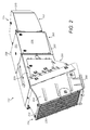
Figure 2 is an external perspective view of the filtration unit offigure 1 ; -
Figure 3 is an external perspective view of a fan unit of the filtration unit offigure 2 with selected parts of the filtration unit removed for illustrative purposes; -
Figure 4 is a further external perspective view of the fan unit offigure 3 from an opposite side with selected parts of the filtration unit removed for illustrative purposes; -
Figure 5 is a further external perspective view of the central region of the filtration unit offigure 2 with selected parts of the filtration unit removed for illustrative purposes; -
Figure 6 is a perspective cross sectional view along the length of the filtration unit offigure 2 ; -
Figure 7 is a rear perspective view of the filtration unit offigure 2 with selected components removed for illustrative purposed; -
Figure 8 is a further cross sectional perspective view from above of the filtration unit offigure 2 ; -
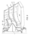
Figure 9 is a magnified cross sectional perspective view from above of the rear sound absorber unit of the filtration unit offigure 2 . - The present filtration unit is described with reference to a preferred embodiment by way of example mounted upon a continuous miner being an electrically powered, track mounted mining machine optimised to cut mineral from a mineral deposit. As will be appreciated, the present filtration unit may be mounted at a variety of different mining machines not restricted to continuous miners.
- Referring to
figure 1 , amining machine 100 comprises amain frame 101 that provides support for an undercarriage orchassis 113 that supports a pair ofendless tracks 110 for propelling themachine 100 over the ground within a mine.Main frame 101 comprises a generallyforward end 102 in a generallyrearward end 103. Aconveyor 104 extends substantially fromforward end 102 torearward end 103 and is adapted to carry material dislodged from the cutting face for subsequent discharge and stock piling at a remote location. Amovable boom 105 is pivotally mounted at oneend 107 tomain frame 101 and comprises asecond end 106 mounting a cutting head indicated generally byreference 108. Cuttinghead 108 comprises a plurality of rotatable drums that mount cuttingbits 109 being specifically adapted to cut into and dislodge the mineral material.Boom 105 and inparticular cutting head 108 is configured to be raised and lowered relative to frame 101 andendless tracks 110 to enablemachine 100 to cut the mineral face over a varying height range above the ground of a mine tunnel. The cut material is gathered by agathering head 111 and is then fed and transferred toconveyor 104. - To inhibit permeation of fine dust particles from the mineral face created by the cutting action of
bits 109 that would otherwise pollute the air surrounding themining machine 100,machine 100 comprises a dust filtration unit indicated generally byreference 112.Filtration unit 112 comprises a series of ducts into which is drawn the contaminant-laden air for filtration and collection of the entrained dust particles.Filtration unit 112 comprises aforward inlet end 114 and a rearwardexhaust end 115 orientated at or towards the respective forward and rearward ends 102, 103 ofmachine 100.Filtration unit 112 is mounted substantially centrally on themachine 100 betweenends - Referring to
figures 2 and3 ,filtration unit 112 comprises three primary components including a fan unit indicated generally byreference 200, a filter duct indicated generally by areference 201 and a sound absorber indicated generally byreference 202. Thefan unit 200 is positioned axially between theforward duct 201 and therearward sound absorber 202. - Referring to
figure 6 ,duct 201 houses aconventional scrubber unit 611 positioned upstream of a plurality ofdemister units 608 that effectively wet the contaminated airflow and then to separate the moistened airstream from the entrained dust particles. Aninlet section 204 ofduct 201 comprises aninlet opening 212 to receive the dust laden airflow immediately behind the cuttinghead 108.Inlet 212 comprises apre-filter screen 205 formed from a mesh-like grid. Anexhaust section 203 ofduct 201 comprises acorresponding outlet 612 provided in fluid communication with thefan unit 200 such that theunit 200 is configured to draw-in air throughinlet 212 andoutlet 612.Filtration unit 112 is mounted atmachine 100 viarigid mounts filter duct 201 and a region in close proximity tofan unit 200. - Referring to
figures 2 and3 fan unit 200 is housed within an isolation box indicated generally byreference 209.Box 209 comprises a front andrear plate base plate side plates 210 that collectively define an internal cavity within which is housedfan unit 200.Front plate 306 is connected to arearward part 307 ofduct 201 whilstrearward plate 312 is connected to aforward part 316 ofsound absorber 202. In particularfront plate 306 is hingebly mounted toduct part 307 via a pair ofhinges 313 so as to allow theentire fan unit 200 andisolation box 209 to hinge outwardly from the outlet end ofduct 201 so as to exposeduct outlet 612. Similarly, therearward sound absorber 202 comprises amount plate 314 that is hingebly mounted to isolation boxrear plate 312 by a pair ofhinges 315. Accordingly, thesound absorber 202 may be hinged laterally outward relative toisolation box 209 to expose the internal chamber offan unit 200.Hinges 315 are isolated via lockingbolts 309 that releasably couple soundabsorber mount plate 314 and rearisolation box plate 312. Corresponding locking bolts are also provided betweenforward box plate 306 andduct part 307.Such bolts 309 may be conveniently removed to allow thevarious components filtration unit 112. -
Fan unit 200 comprises a generally cylindrical drum-shapedhousing 300 having radially extendingconnection flange 303 at an axially forward end and acorresponding flange 303 at an axially rearward end. Eachannular flange 303 is secured to a correspondingannular flange 304 of a respective axially forwardflexible coupling 301 and an identical axially rearwardflexible coupling 302. Eachflexible coupling flange 305 attached respectively to forward andrearward plates housing 300 andflexible couplings isolation box 209. In particular,housing 300 is suspended in 'floating' coupled relationship between theflexible couplings housing 300 is not rigidly mounted toisolation box 209,rigid mount 207 and/ormachine frame 101. -
Fan unit 200 and inparticular housing 300 is supported further by an additionalelastomeric coupling 319 in a form of plurality of elastically compressible annular bushings. Eachbushing 319 is mounted at a lower end at abase mount 320 that is rigidly connected tobase plate 317. An upper end of eachbushing 319 is connected to awing plate 318 that projects laterally from a lower region of housing 300 a short distance abovebase plate 317. Accordingly,housing 300 and inparticular fan unit 200 is suspended in the floating coupled relationship within theisolation box 209 via elasticallydeformable couplings housing 300 and the internal components within the fan unit (identified below) are mounted and supported exclusively via theflexible couplings fan unit 200 and inparticular housing 300 is elastically suspended within theisolation box 209 which is then in turn coupled to theforward duct 201 and therearward sound absorber 202. According to further specific implementations,axial couplings duct 201 andsound absorber 202 viaflanges 305 or similar. However, the present implementation is advantageous to allow theentire fan unit 200 to be conveniently removed and reinstalled atmachine 100. Additionally, the hinge mountings of thefan unit 200 atduct 201 and therear sound absorber 202 atisolation box 209 facilitates maintenance and repair of the internal components within thefiltration unit 112 as access may be gained to the internal components without having to decouple completely thevarious components -
Isolation box 209 is specifically adapted atbase plate 317 to receive hose ends 321 that supply hydraulic fluid to the fan motor accommodated withinhousing 300. The hoses and/or hose ends 321 may be flexible so as to be compatible with the flexible suspension of thehousing 300 within thefiltration unit 112. - Referring to
figure 4 noise emission fromfan unit 200 is further suppressed via the surround mounting of a plurality of sound absorption blocks 400. Eachblock 400 comprises a generally wedge-shaped profile that is accommodated in the cavity region betweenfan housing 300 and the internal surfaces ofisolation box 209.Handles 402 may be provided at eachblock 400 to allow convenient removal and installation.Blocks 400 are conveniently wedged in position to surround thehousing 300 and may be accessed by removal of side androof panels - Referring to
figures 5 and6 ,duct exhaust section 203 comprises an upperairflow directing blade 500 and a lowerairflow directing blade 501.Blades blade duct section 203. Eachblade leading edge 504 orientated towardsduct inlet 212 and a trailingedge 505 orientated towardsoutlet 612. Eachblade leading end 504 is lower than trailingend 505. Air flows above, below and betweenblades blade internal skeleton 507 formed from a sheet material surrounded by asound absorbing material 506. Eachblade Blades duct exhaust section 203 and to absorb sound as the airflow passes above, below and between the pair of vertically separatedblades - A
first pressure sensor 502 and asecond pressure sensor 503 are positioned at a region betweenblades rearward sensor 503 is positioned slightly higher than theforward sensor 502. Eachsensor transmitter unit 322 mounted withinisolation box 209.Suitable cabling 323 extends to couplesensors unit 322.Sensors sensors -
Fan unit 200 comprises ahollow fan body 600 that houses an internalhydraulic motor 601. Anaxel 613 extends rearwardly frommotor 601 to mount a fan wheel comprising a plurality of fan blades (not shown) that extend radially betweenfan body 600 and the internal surface offan housing 300.Fan body 600 comprises anose cone 602 having a generally semi-spherical configuration that acts to control and guide the airflow axiallypast body 600. A set of fan static wings (not shown) are mounted immediately downstream of fan blades. The rotatably mounted fan wheel is mounted athousing region 604 and the static wings are mounted athousing region 605. Aconical tail section 603 projects rearwardly from the static wings mounted atregion 605 so as to enhance the aerodynamics of thefan body 600 as the flow of air is exhausted into thesound absorber 202. According to the specific implementation,conical tail 603 extends axially from the rearward end offan unit 200 and into the internal chamber ofsound absorber 202. -
Sound absorber 202 is generally hollow and is defined by aroof plate 614, abase plate 615 and a pair ofopposed sidewalls 806. A plurality ofairflow directing vanes 609 are accommodated withinabsorber 202 to extend lengthwise between an inlet and outlet of theabsorber 202. In particular, and referring tofigures 8 and9 , eachvane 609 is curved along its length (in a direction of the absorber inlet and outlet) with eachvane 609 extending in a vertical direction between the roof andbase plates vane 609 and thesidewalls 806 so as to direct and control the exhaust airflow fromoutlet 213. - Referring to
figures 8 and9 eachvane 609 comprises a thickness in a direction betweenwalls 806 that is tapered to increase from aleading end 800 to reach a maximum and then to decrease towards a trailingend 801. The variable thickness of eachvane 609 along its length is configured to assist with directing the airflow withinabsorber 202 and to specifically absorb sound of different frequencies. According to the specific implementation, three blades are suspended betweensidewalls 806 and are spaced apart substantially evenly in a widthwise direction betweenwalls 806. Eachvane 609 is generally thicker (in the widthwise direction) at an axially forward half closest to leadingend 800 than a corresponding rearward half. Additionally, two of thevanes 609 comprise generally planar rearward sections positioned closest to trailing ends 801. Eachsidewall 806 comprises a curved internal shape profile matching the curved shaped profile of theadjacent vane 609. - Each
vane 609 comprises a modular construction having aninternal support 804 in the form of a sheet like plate.Plate 804 is surrounded by asound absorbing material 805 which is in turn coated by an outer skin orlayer Layer vane 609. - To further enhance the sound absorbing characteristic of the
filtration unit 112, the internal facing surfaces offilter duct 201 andsound absorber 202 are coated with a sound absorbing material such as a perforated sheet like material.
Claims (15)
- A dust filtration unit (112) mountable at a mining machine (100) having a main frame (101), the unit (112) comprising:a filter duct (201) having at least one filter (608) to filter airborne contaminants generated by the machine (100), the filter duct (201) having an inlet (212) to receive an air flow containing the airborne contaminants and an outlet (612) to discharge a filtered airflow;a fan unit (200) to drive the airflow through the filter duct (201), the fan unit (200) coupled to a region of the outlet (612) of the filter duct (201);a sound absorber unit (202) positioned at an exhaust end of the fan unit (200) configured to dampened sound emission from the fan unit (200);characterised by:a first flexible coupling (302) positioned axially between the fan unit (200) and the sound absorber unit (202) to inhibit the transmission of vibrational forces from the fan unit (200) to the sound absorber unit (202).
- The unit as claimed in claim 1 comprising a second flexible coupling (319) positioned between the fan unit (200) and the frame (101) to inhibit the transmission of vibrational forces from the fan unit (200) to the frame (101); and/or
a third flexible coupling (301) positioned axially between the filter duct (201) and the fan unit (200) to inhibit the transmission of vibrational forces from the fan unit (200) to the filter duct (201). - The unit as claimed in claim 1 or 2 wherein an internal volume of the sound absorber unit (202) is substantially equal to or greater than an internal volume of the fan unit (200).
- The unit as claimed in any one of claims 1 to 3 comprising a plurality of air flow directing vanes (609) housed internally within the sound absorber unit (202) and extending in a lengthwise direction between an inlet (616) and an outlet (213) of the sound absorber unit (202);
wherein each vane (609) comprises a curved or bent region along its length configured to absorb sound as the air flows through the sound absorber unit (202). - The unit as claimed in claim 4 wherein each vane (609) comprises a forward end (800) and a rearward end (801) and a thickness of each vane (609) perpendicular to a length of each vane (609) is non-uniform between the forward (800) and rearward (801) end.
- The unit as claimed in claim 5 wherein a thickness of each vane (609) between the forward (800) and rearward (801) ends increases to maximum and then decreases.
- The unit as claimed in any preceding claim wherein a region of the filter duct (201) comprises air flow directing blades (500, 501) extending generally in a lengthwise direction between the inlet (212) and outlet (612) of the filter duct (201).
- The unit as claimed in claim 7 wherein each blade (500, 501) comprises a forward end (504) and a rearward end (505) and a thickness of each blade (500, 501) perpendicular to a length between the forward (504) and rearward (505) ends decreases from a forward region at the forward end (504) to a rearward region at the rearward end (505).
- The unit as claimed in any one of claims 4 to 8 wherein each vane (609) and/or each blade (500, 501) is coated with a sound absorbing material.
- The unit as claimed in any preceding claim wherein the first (302) and third (301) flexible couplings are generally tubular and the fan unit (200), the sound absorber unit (202) and the first (302) and third (301) flexible couplings are mounted to be aligned substantially coaxially.
- The unit as claimed in any preceding claim wherein the first (302), second (319) and/or third (301) flexible couplings comprise a resiliently deformable material.
- The unit as claimed in any preceding claim wherein the fan unit (200) comprises a fan body (600) mounted internally within the fan unit (200), the fan body (600) mounting a plurality of fan blades and comprising a domed or conical nose (602) at a forward end and a domed or conical tail (603) at an opposite rearward end.
- The unit as claimed in any one of claims 7 to 8 comprising at least two pressure sensors (502, 503) mounted at or at a region of the blades (500, 501) to monitor any one of a combination of:• air pressure within the filter duct (201)• air pressure at a region between the blades (500, 501)• air pressure at a region above or below the blades (500, 501); to determine an airflow through the unit.
- The unit as claimed in any preceding claim comprising an isolation box (209) that is formed as a casing for the fan unit (200) and is mounted to the frame (101).
- A mining machine (100) comprising:a main frame (101);a movable boom (105) pivotally attached to the main frame (101) and mounting a cutting head (108) at or towards one end (106) of the boom (105); anda filtration unit (112) as claimed in any preceding claim.
Priority Applications (3)
| Application Number | Priority Date | Filing Date | Title |
|---|---|---|---|
| EP14156350.2A EP2910732A1 (en) | 2014-02-24 | 2014-02-24 | Mining machine filtration unit with minimised sound emission |
| PCT/EP2015/053182 WO2015124516A2 (en) | 2014-02-24 | 2015-02-16 | Mining machine filtration unit with minimised sound emission |
| CN201580004442.6A CN105917076A (en) | 2014-02-24 | 2015-02-16 | Mining machine filter unit with minimized sound emissions |
Applications Claiming Priority (1)
| Application Number | Priority Date | Filing Date | Title |
|---|---|---|---|
| EP14156350.2A EP2910732A1 (en) | 2014-02-24 | 2014-02-24 | Mining machine filtration unit with minimised sound emission |
Publications (1)
| Publication Number | Publication Date |
|---|---|
| EP2910732A1 true EP2910732A1 (en) | 2015-08-26 |
Family
ID=50193225
Family Applications (1)
| Application Number | Title | Priority Date | Filing Date |
|---|---|---|---|
| EP14156350.2A Withdrawn EP2910732A1 (en) | 2014-02-24 | 2014-02-24 | Mining machine filtration unit with minimised sound emission |
Country Status (3)
| Country | Link |
|---|---|
| EP (1) | EP2910732A1 (en) |
| CN (1) | CN105917076A (en) |
| WO (1) | WO2015124516A2 (en) |
Cited By (1)
| Publication number | Priority date | Publication date | Assignee | Title |
|---|---|---|---|---|
| US9873142B2 (en) * | 2015-05-04 | 2018-01-23 | Caterpillar Paving Products Inc. | Cold planer exhaust system with access doors |
Families Citing this family (5)
| Publication number | Priority date | Publication date | Assignee | Title |
|---|---|---|---|---|
| RU2765174C2 (en) * | 2017-05-02 | 2022-01-26 | Джой Глобал Серфейс Майнинг Инк | Air filtration for a self-propelled mining machine |
| CN107605478A (en) * | 2017-09-27 | 2018-01-19 | 辽宁工程技术大学 | A kind of continuous mining machine |
| CN113217069B (en) * | 2021-06-15 | 2023-12-01 | 云南滇东雨汪能源有限公司 | Ventilation device for preventing coal mine gas from exceeding limit |
| CN114017027B (en) * | 2021-10-27 | 2024-07-09 | 中国煤炭科工集团太原研究院有限公司 | Intelligent dust removing robot suitable for continuous miner and tunneling and anchoring integrated machine |
| WO2024020400A1 (en) * | 2022-07-18 | 2024-01-25 | Virginia Tech Intellectual Properties Inc. | Filter system for removing dust particles from underground mining and methods of use thereof |
Citations (17)
| Publication number | Priority date | Publication date | Assignee | Title |
|---|---|---|---|---|
| US2030367A (en) * | 1933-12-11 | 1936-02-11 | Grave Otto | Electric vacuum cleaner |
| US3387889A (en) | 1966-11-03 | 1968-06-11 | Stanley C. Ziemba | Coal dust removal and conveyance system |
| US3712678A (en) | 1971-03-18 | 1973-01-23 | Lee Noise Co | Mining machine having dust collecting means |
| US3743356A (en) | 1972-01-27 | 1973-07-03 | G Sheets | Coal dust removal and coal transportation system |
| US4248611A (en) * | 1979-05-10 | 1981-02-03 | Dresser Industries, Inc. | Mining machine |
| US4330047A (en) * | 1979-10-05 | 1982-05-18 | Centro Ricerche Fiat S.P.A. | Sound-attenuating ventilation |
| US4348057A (en) * | 1980-08-25 | 1982-09-07 | B & J Manufacturing Company | Blower and dust collecting machine and method of operation |
| DE3137746A1 (en) * | 1981-09-23 | 1983-06-09 | Volkswagenwerk Ag, 3180 Wolfsburg | Exhaust system for the internal combustion engine of a vehicle |
| GB2263294A (en) | 1992-01-17 | 1993-07-21 | Tamrock World Corp | Method and apparatus for collecting and removing dust on a mining machine |
| US5597393A (en) | 1994-07-06 | 1997-01-28 | Joy Mm Delaware Inc. | Displaceable filtering apparatus for airborne contaminates |
| US5983888A (en) * | 1999-04-07 | 1999-11-16 | Whirlpool Corporation | Low noise cooker hood |
| JP2004198271A (en) * | 2002-12-19 | 2004-07-15 | Yamatake Corp | Duct flow measurement device |
| EP1486642A2 (en) | 2003-06-13 | 2004-12-15 | Cft Gmbh Compact Filter Technic | Dust remover with multi-jet nozzles |
| EP1503033A1 (en) | 2003-07-29 | 2005-02-02 | Cft Gmbh Compact Filter Technic | Apparatus for generating an air current in a sound-isolated dust remover |
| DE10334600A1 (en) | 2003-07-29 | 2005-02-24 | Cft Gmbh Compact Filter Technic | Dust removal and ventilation unit to be used in mining and tunneling, comprising housings to be joined and noise absorbing units at inlet and outlet |
| US20060104028A1 (en) * | 2004-11-16 | 2006-05-18 | Patel Chandrakant D | Ventilated casing for an electronic device |
| JP2009155996A (en) * | 2007-12-28 | 2009-07-16 | Ryuki Engineering:Kk | Drilling system |
Family Cites Families (2)
| Publication number | Priority date | Publication date | Assignee | Title |
|---|---|---|---|---|
| AU2010220816B2 (en) * | 2009-03-03 | 2015-05-14 | Particular Engineering Pty Ltd | Dust scrubber |
| EP2789796A1 (en) * | 2013-04-08 | 2014-10-15 | Sandvik Intellectual Property AB | Mining machine filtering unit with sound absorber |
-
2014
- 2014-02-24 EP EP14156350.2A patent/EP2910732A1/en not_active Withdrawn
-
2015
- 2015-02-16 WO PCT/EP2015/053182 patent/WO2015124516A2/en not_active Ceased
- 2015-02-16 CN CN201580004442.6A patent/CN105917076A/en active Pending
Patent Citations (17)
| Publication number | Priority date | Publication date | Assignee | Title |
|---|---|---|---|---|
| US2030367A (en) * | 1933-12-11 | 1936-02-11 | Grave Otto | Electric vacuum cleaner |
| US3387889A (en) | 1966-11-03 | 1968-06-11 | Stanley C. Ziemba | Coal dust removal and conveyance system |
| US3712678A (en) | 1971-03-18 | 1973-01-23 | Lee Noise Co | Mining machine having dust collecting means |
| US3743356A (en) | 1972-01-27 | 1973-07-03 | G Sheets | Coal dust removal and coal transportation system |
| US4248611A (en) * | 1979-05-10 | 1981-02-03 | Dresser Industries, Inc. | Mining machine |
| US4330047A (en) * | 1979-10-05 | 1982-05-18 | Centro Ricerche Fiat S.P.A. | Sound-attenuating ventilation |
| US4348057A (en) * | 1980-08-25 | 1982-09-07 | B & J Manufacturing Company | Blower and dust collecting machine and method of operation |
| DE3137746A1 (en) * | 1981-09-23 | 1983-06-09 | Volkswagenwerk Ag, 3180 Wolfsburg | Exhaust system for the internal combustion engine of a vehicle |
| GB2263294A (en) | 1992-01-17 | 1993-07-21 | Tamrock World Corp | Method and apparatus for collecting and removing dust on a mining machine |
| US5597393A (en) | 1994-07-06 | 1997-01-28 | Joy Mm Delaware Inc. | Displaceable filtering apparatus for airborne contaminates |
| US5983888A (en) * | 1999-04-07 | 1999-11-16 | Whirlpool Corporation | Low noise cooker hood |
| JP2004198271A (en) * | 2002-12-19 | 2004-07-15 | Yamatake Corp | Duct flow measurement device |
| EP1486642A2 (en) | 2003-06-13 | 2004-12-15 | Cft Gmbh Compact Filter Technic | Dust remover with multi-jet nozzles |
| EP1503033A1 (en) | 2003-07-29 | 2005-02-02 | Cft Gmbh Compact Filter Technic | Apparatus for generating an air current in a sound-isolated dust remover |
| DE10334600A1 (en) | 2003-07-29 | 2005-02-24 | Cft Gmbh Compact Filter Technic | Dust removal and ventilation unit to be used in mining and tunneling, comprising housings to be joined and noise absorbing units at inlet and outlet |
| US20060104028A1 (en) * | 2004-11-16 | 2006-05-18 | Patel Chandrakant D | Ventilated casing for an electronic device |
| JP2009155996A (en) * | 2007-12-28 | 2009-07-16 | Ryuki Engineering:Kk | Drilling system |
Cited By (1)
| Publication number | Priority date | Publication date | Assignee | Title |
|---|---|---|---|---|
| US9873142B2 (en) * | 2015-05-04 | 2018-01-23 | Caterpillar Paving Products Inc. | Cold planer exhaust system with access doors |
Also Published As
| Publication number | Publication date |
|---|---|
| WO2015124516A3 (en) | 2015-11-05 |
| WO2015124516A2 (en) | 2015-08-27 |
| CN105917076A (en) | 2016-08-31 |
Similar Documents
| Publication | Publication Date | Title |
|---|---|---|
| WO2015124516A2 (en) | Mining machine filtration unit with minimised sound emission | |
| AU2010220816B2 (en) | Dust scrubber | |
| CN102003200A (en) | Small mining combined dust remover | |
| CN103476996A (en) | Local Dust Extraction Systems for Excavators | |
| AU539609B2 (en) | Cowl-like scrubber for a long-wall shearer | |
| US9856834B2 (en) | Filter pre-cleaner system | |
| CN112360459B (en) | Comprehensive dustproof method for rapid tunneling working face | |
| CN206144595U (en) | Dust pelletizing system for tunnel boring machine | |
| CN107559007A (en) | A kind of digging laneway dust goes out except device | |
| CN116398217A (en) | A Controlled Dust Reduction System for Excavation Working Face | |
| EP2789796A1 (en) | Mining machine filtering unit with sound absorber | |
| CN104968891B (en) | mining machine filter | |
| CN216654682U (en) | A kind of crushing device for mining machinery | |
| CN214403430U (en) | Down-the-hole hammer drill for down-the-hole hammer drilling | |
| CN203879504U (en) | Continuous dust removal device of coal mining machine | |
| CN216566674U (en) | Coal mine ventilation device with external protection structure | |
| CN117900027B (en) | An air circulation filter for shotcrete in underground coal mine tunnels | |
| CN119982037A (en) | A dust suppression device based on underground tunnel development and excavation | |
| CN113908911A (en) | Energy-efficient type mineral screening equipment | |
| CN209752397U (en) | Mine dust collecting equipment for environmental protection | |
| CN118997757A (en) | Coal-winning machine airborne dust pelletizing system and coal-winning machine | |
| CN115288766B (en) | A dust-free coal roadway excavation method | |
| CN211474054U (en) | Protective device for crawler drill | |
| CN224174138U (en) | Dry-type drilling three-proofing pneumatic curve conveying device | |
| CN201972724U (en) | Small-sized combined mining dust collector |
Legal Events
| Date | Code | Title | Description |
|---|---|---|---|
| PUAI | Public reference made under article 153(3) epc to a published international application that has entered the european phase |
Free format text: ORIGINAL CODE: 0009012 |
|
| 17P | Request for examination filed |
Effective date: 20140224 |
|
| AK | Designated contracting states |
Kind code of ref document: A1 Designated state(s): AL AT BE BG CH CY CZ DE DK EE ES FI FR GB GR HR HU IE IS IT LI LT LU LV MC MK MT NL NO PL PT RO RS SE SI SK SM TR |
|
| AX | Request for extension of the european patent |
Extension state: BA ME |
|
| RBV | Designated contracting states (corrected) |
Designated state(s): AL AT BE BG CH CY CZ DE DK EE ES FI FR GB GR HR HU IE IS IT LI LT LU LV MC MK MT NL NO PL PT RO RS SE SI SK SM TR |
|
| STAA | Information on the status of an ep patent application or granted ep patent |
Free format text: STATUS: THE APPLICATION IS DEEMED TO BE WITHDRAWN |
|
| 18D | Application deemed to be withdrawn |
Effective date: 20160625 |