EP2910731A1 - Monitoring well effluent plunger lift operations - Google Patents
Monitoring well effluent plunger lift operations Download PDFInfo
- Publication number
- EP2910731A1 EP2910731A1 EP14156297.5A EP14156297A EP2910731A1 EP 2910731 A1 EP2910731 A1 EP 2910731A1 EP 14156297 A EP14156297 A EP 14156297A EP 2910731 A1 EP2910731 A1 EP 2910731A1
- Authority
- EP
- European Patent Office
- Prior art keywords
- plunger
- well
- wellbore
- production
- deposits
- Prior art date
- Legal status (The legal status is an assumption and is not a legal conclusion. Google has not performed a legal analysis and makes no representation as to the accuracy of the status listed.)
- Pending
Links
- 238000012544 monitoring process Methods 0.000 title claims abstract description 15
- 238000004519 manufacturing process Methods 0.000 claims abstract description 81
- 239000004215 Carbon black (E152) Substances 0.000 claims abstract description 43
- 229930195733 hydrocarbon Natural products 0.000 claims abstract description 43
- 150000002430 hydrocarbons Chemical class 0.000 claims abstract description 43
- 239000012530 fluid Substances 0.000 claims abstract description 40
- 239000000835 fiber Substances 0.000 claims abstract description 25
- 230000003287 optical effect Effects 0.000 claims abstract description 25
- 239000007787 solid Substances 0.000 claims abstract description 17
- 239000007788 liquid Substances 0.000 claims abstract description 16
- VNWKTOKETHGBQD-UHFFFAOYSA-N methane Chemical compound C VNWKTOKETHGBQD-UHFFFAOYSA-N 0.000 claims description 32
- 238000000034 method Methods 0.000 claims description 26
- 239000003345 natural gas Substances 0.000 claims description 16
- 238000009825 accumulation Methods 0.000 claims description 12
- 239000007789 gas Substances 0.000 claims description 10
- -1 condensates Substances 0.000 claims description 7
- 230000001788 irregular Effects 0.000 claims description 6
- 230000004044 response Effects 0.000 claims description 6
- 238000013459 approach Methods 0.000 claims description 5
- 230000008021 deposition Effects 0.000 claims description 5
- 239000002245 particle Substances 0.000 claims description 5
- 230000005534 acoustic noise Effects 0.000 claims description 4
- 239000000203 mixture Substances 0.000 claims description 4
- 239000002244 precipitate Substances 0.000 claims description 4
- XLYOFNOQVPJJNP-UHFFFAOYSA-N water Substances O XLYOFNOQVPJJNP-UHFFFAOYSA-N 0.000 claims description 4
- 230000005012 migration Effects 0.000 claims description 3
- 238000013508 migration Methods 0.000 claims description 3
- 239000013307 optical fiber Substances 0.000 claims description 3
- 125000004122 cyclic group Chemical group 0.000 claims description 2
- 230000001939 inductive effect Effects 0.000 claims description 2
- 230000001960 triggered effect Effects 0.000 abstract 1
- 238000004140 cleaning Methods 0.000 description 5
- 230000004907 flux Effects 0.000 description 4
- 230000015572 biosynthetic process Effects 0.000 description 2
- 238000001514 detection method Methods 0.000 description 2
- 230000004941 influx Effects 0.000 description 2
- 230000000712 assembly Effects 0.000 description 1
- 238000000429 assembly Methods 0.000 description 1
- 239000004568 cement Substances 0.000 description 1
- 239000004927 clay Substances 0.000 description 1
- 230000005484 gravity Effects 0.000 description 1
- 238000007689 inspection Methods 0.000 description 1
- 238000012423 maintenance Methods 0.000 description 1
- 230000007246 mechanism Effects 0.000 description 1
- 238000012986 modification Methods 0.000 description 1
- 230000004048 modification Effects 0.000 description 1
- 238000005457 optimization Methods 0.000 description 1
- 239000003208 petroleum Substances 0.000 description 1
- 238000012545 processing Methods 0.000 description 1
- 239000011435 rock Substances 0.000 description 1
- 239000004576 sand Substances 0.000 description 1
- 238000006748 scratching Methods 0.000 description 1
- 230000002393 scratching effect Effects 0.000 description 1
Images


Classifications
-
- E—FIXED CONSTRUCTIONS
- E21—EARTH OR ROCK DRILLING; MINING
- E21B—EARTH OR ROCK DRILLING; OBTAINING OIL, GAS, WATER, SOLUBLE OR MELTABLE MATERIALS OR A SLURRY OF MINERALS FROM WELLS
- E21B47/00—Survey of boreholes or wells
- E21B47/008—Monitoring of down-hole pump systems, e.g. for the detection of "pumped-off" conditions
-
- E—FIXED CONSTRUCTIONS
- E21—EARTH OR ROCK DRILLING; MINING
- E21B—EARTH OR ROCK DRILLING; OBTAINING OIL, GAS, WATER, SOLUBLE OR MELTABLE MATERIALS OR A SLURRY OF MINERALS FROM WELLS
- E21B43/00—Methods or apparatus for obtaining oil, gas, water, soluble or meltable materials or a slurry of minerals from wells
- E21B43/12—Methods or apparatus for controlling the flow of the obtained fluid to or in wells
- E21B43/121—Lifting well fluids
-
- E—FIXED CONSTRUCTIONS
- E21—EARTH OR ROCK DRILLING; MINING
- E21B—EARTH OR ROCK DRILLING; OBTAINING OIL, GAS, WATER, SOLUBLE OR MELTABLE MATERIALS OR A SLURRY OF MINERALS FROM WELLS
- E21B47/00—Survey of boreholes or wells
- E21B47/12—Means for transmitting measuring-signals or control signals from the well to the surface, or from the surface to the well, e.g. for logging while drilling
- E21B47/13—Means for transmitting measuring-signals or control signals from the well to the surface, or from the surface to the well, e.g. for logging while drilling by electromagnetic energy, e.g. radio frequency
- E21B47/135—Means for transmitting measuring-signals or control signals from the well to the surface, or from the surface to the well, e.g. for logging while drilling by electromagnetic energy, e.g. radio frequency using light waves, e.g. infrared or ultraviolet waves
-
- E—FIXED CONSTRUCTIONS
- E21—EARTH OR ROCK DRILLING; MINING
- E21B—EARTH OR ROCK DRILLING; OBTAINING OIL, GAS, WATER, SOLUBLE OR MELTABLE MATERIALS OR A SLURRY OF MINERALS FROM WELLS
- E21B47/00—Survey of boreholes or wells
- E21B47/10—Locating fluid leaks, intrusions or movements
- E21B47/107—Locating fluid leaks, intrusions or movements using acoustic means
Definitions
- the invention relates to a method and system for monitoring well effluent plunger lift operations, wherein a plunger moves cyclically up and down through an underground wellbore to remove well effluent deposits therefrom.
- US patent 6,634,426 discloses a method for optimizing plunger lift operations by "Counting Collars", wherein acoustic noise generated when the plunger passes an irregular tubing joint is monitored using an acoustic sensor in the wellhead assembly, which sensor also counts the number of joints passed by the plunger to determine the depth of the plunger in the well.
- This known technique requires the presence of irregular tubing joints and cannot be used in wells equipped with coiled production tubing assemblies.
- US patent application 20120323493 discloses the use of magnetic detectors in a wellhead assembly for detecting plunger arrival.
- US patent application 20120193091 discloses the use of a sound-generating plunger to monitor plunger velocity in the wellbore.
- a method for monitoring well effluent plunger lift operations wherein well effluent deposits are removed from a hydrocarbon fluid production well by a plunger that cyclically moves up and down through the wellbore comprising:
- the method may further comprise optimizing the plunger lift operation and associated production of hydrocarbon fluid and well deposits in response to the acoustic signals recorded by the fiber optical Distributed Vibration Sensing (DVS)assembly relating to at least one of the vibration triggering events a)-j).
- DVD Distributed Vibration Sensing
- the hydrocarbon production well may be a natural gas production well and the fiber optical Distributed Vibration Sensing(DVS) assembly may comprise an optical fiber which extends along at least a substantial part of length of the wellbore, and is in acoustic contact with, an outer surface of a production tubing through which a multiphase well effluent mixture comprising natural gas and at least some liquid, viscous and/or solid well effluent components, such as water, condensates, wax, asphaltenes, precipitates and/or solid particles, are produced, and the plunger moves cyclically up and down through the production tubing to remove any well effluent deposits comprising the liquid, viscous and/or solid components from the interior of the production tubing.
- a multiphase well effluent mixture comprising natural gas and at least some liquid, viscous and/or solid well effluent components, such as water, condensates, wax, asphaltenes, precipitates and/or solid particles
- the production tubing comprises a permeable inflow region above a bottom of the well and the wellhead comprises a lubricator located above a well effluent outlet provided with a production choke and the plunger is cyclically moved up and down between the bottom of the well and the lubricator.
- cyclic motion of the plunger may comprise the following phases:
- the production of well effluents may be controlled by varying the opening of the production choke in response to information provided by the DVS assembly about the location and upward velocity of the plunger through the production tubing.
- the fiber optical Distributed Vibration Sensing (DVS) assembly may be configured to monitor a location of a liquid-gas interface above a deposition of well effluents in the production tubing by monitoring noise associated by migration of the plunger and/or natural gas through the deposition and/or any temperature differences between the plunger, the natural gas and the deposition and the thus monitored location of the liquid-gas interface may be subsequently used as an input to a production choke control system to control the position of the production choke and the position and movement of the plunger within the production tubing, and/or to optimize the liquid unloading phase of the well, and/or a duration of the after-flow phase during which the plunger is arranged in a surface lubricator in the wellhead above the production choke and and/or a duration of the shut-in phase during which the production choke is closed and the plunger falls from the wellhead to a bottom of the well.
- a production choke control system to control the position of the production choke and the position and movement of the plunger within the production tubing, and
- a system for monitoring well effluent plunger lift operations wherein well effluent deposits are removed from a hydrocarbon fluid production well by a plunger that cyclically moves up and down through the wellbore comprising:
- the system may further comprise means for optimizing the plunger lift operation and associated production of hydrocarbon fluid and well deposits in response to the vibrations recorded by the fiber optical Distributed Vibration Sensing (DVS)assembly relating to at least one of the vibration triggering events a)-j).
- DVD Distributed Vibration Sensing
- the plunger may comprise an acoustic source that is configured to transmit an acoustic noise that is detectable by the fiber optical Distributed Vibration Sensing (DVS) assembly.
- DVD Fiber optical Distributed Vibration Sensing
- the Distributed Vibration Sensing (DVS) assembly may be configured to monitor acoustic events with frequencies of less than 50 Hz, optionally frequencies of less than 20 Hz, in particular frequencies below 10 Hz.
- Figures 1-4 show a hydrocarbon fluid production well that is cleaned by a plunger lift well cleaning operation wherein a plunger 1 is moved up and down through a production tubing 2 within the wellbore 3 to lift liquid and solid deposits 4 to hydrocarbon fluid processing facilities (not shown) at the earth surface 5.
- the plunger 1 is located at the bottom 6 of the wellbore 3 below a perforated well effluent influx zone 7 in which the perforations 15 have been shot through the production tubing 2, and through the gravel pack 8, the well casing or liner 9 and the surrounding hydrocarbon bearing formation 10 to permit influx, as illustrated by arrows 11 of a multiphase mixture of well effluents comprising natural gas and solid and/or liquid components, such as water, condensates, wax, asphaltenes and/or other precipitates and/or formation particles, such as rock, sand and/or clay particles, flow into the production tubing 2.
- natural gas and solid and/or liquid components such as water, condensates, wax, asphaltenes and/or other precipitates and/or formation particles, such as rock, sand and/or clay particles
- At least a fraction of the solid and/or liquid components may be dragged by the flux of natural gas illustrated by arrows 11 to the wellhead 12 and at least another fraction of the solid and/or liquid components may accumulate in a gradually increasing pool 13 of well deposits through which natural gas bubbles 14 travel in upward direction as illustrated by arrows 11.
- a fiber optical Distributed Vibration Sensing (DVS) cable 16 is bonded to the outer surface of the production tubing 2 and is connected to a DVS interrogation assembly 17, which is configured to monitor vibrations resulting from acoustic and/or thermal events within the wellbore 3, such as the noise generated by the flux of natural gas bubbles 14 through the pool 13 of well deposits.
- DVS interrogation assembly 17 which is configured to monitor vibrations resulting from acoustic and/or thermal events within the wellbore 3, such as the noise generated by the flux of natural gas bubbles 14 through the pool 13 of well deposits.
- the DVS interrogation assembly 17 indicates that the level of the pool 13 of well deposit reaches a level at which production of natural gas is inhibited then the production choke 31 may be fully opened so that the well effluents drag the plunger 1 to surface.
- Figure 2 shows the well onloading phase during which the thus released plunger 1 is further pushed up, as illustrated by arrow 20, by the flux of well effluents 11 through the production tubing 2 and thereby also pushes the pool 13 of well deposits up towards the wellhead 12.
- the plunger 1 may or may not be equipped with fins 21 that may not fully seal off the annular space between the plunger 1 and the inner surface of the production tubing 2, so that a residual fraction of the produced natural gas still migrates as gas bubbles 14 through the annular space and the pool of well deposits 13 above the plunger, thereby allowing the DVS interrogation assembly 17 to monitor the upward migration and size of the pool of well deposits 13 as it is pushed by the plunger 1 towards the wellhead 12.
- the DVS interrogation assembly 17 is also configured to monitor acoustic events associated with the upward movement of the plunger 1 through the production tubing 2, such as the scratching of the fins 21 and/or other parts of the outer surface of the plunger 1 along the inner surface and/or tubing joints of the production tubing 2, and/or whistling noise generated by the residual fraction of natural gas flowing through any remaining gaps between the fins 21 and/or other parts of the outer surface of the plunger 1 and the inner surface of the production tubing 2.
- Figure 3 shows the well during an afterflow phase during which the plunger 1 is located within a lubricator 30 in the wellhead assembly 12.
- the DVS interrogation assembly 17 monitors the position and upward velocity of the plunger 1 and induces, if the upward velocity of the plunger is too high when it approaches the wellhead assembly 12, a gradual closing of the production choke 31 and/or bypass valve 32 at the wellhead outlet conduits 33 and 34, thereby reducing the flux of well effluents 35 and the associated upward velocity of the plunger 1.
- the bypass valve 32 and a lubricator valve 36 are closed, so that the lubricator 30 is isolated from the wellbore 3 and may be opened to retrieve the plunger 1 from the well for maintenance, inspection or replacement wherein the plunger 1 may be cleaned, worn fins 21 may be replaced and/or a spring and/or bladder actuated plunger release mechanism may be re-activated.
- the production choke 31 is closed and the lubricator valve 36 is opened to allow the plunger 1 to be lowered by gravity forces to the bottom 6 of the wellbore 3 as illustrated in Figure 4 .
- noise 40 When the plunger 1 descends through the wellbore 3 noise 40 will be generated by friction between the fins 21 and/or other parts of the outer surface of the plunger 1 and the inner surface of the tubing 3 tubing joints and/or perforations 15. This noise 40 is monitored by the fiber optical DVS cable 16 and associated DVS interrogation assembly 17, so that the position and downward motion of the plunger 1 are accurately monitored. Once the DVS interrogation assembly 17 indicates that the plunger 1 reaches the bottom 6 of the wellbore 3 the production choke 31 or bypass valve 32 is opened so that well effluent production is re-started and the produced well effluents drag the plunger 1 to surface.
- the plunger 1 may be equipped with an acoustic source, such as a whistle and/or battery powered microphone that transmits a noise 40 that can be accurately monitored by the fiber optical DVS cable 16 and associated DVS interrogation assembly 17.
- an acoustic source such as a whistle and/or battery powered microphone that transmits a noise 40 that can be accurately monitored by the fiber optical DVS cable 16 and associated DVS interrogation assembly 17.
- the DVS cable may be embedded in a cement annulus surrounding the well casing or liner 9 instead of an annular space between the production tubing 2 and well casing or liner 9.
Landscapes
- Engineering & Computer Science (AREA)
- Life Sciences & Earth Sciences (AREA)
- Mining & Mineral Resources (AREA)
- Geology (AREA)
- Physics & Mathematics (AREA)
- Environmental & Geological Engineering (AREA)
- Fluid Mechanics (AREA)
- General Life Sciences & Earth Sciences (AREA)
- Geochemistry & Mineralogy (AREA)
- Remote Sensing (AREA)
- Geophysics (AREA)
- Electromagnetism (AREA)
- Measurement Of Mechanical Vibrations Or Ultrasonic Waves (AREA)
Abstract
Well effluent plunger lift operations, wherein a plunger (1) cyclically moves up and down through a hydrocarbon fluid production well to remove solid, viscous and/or liquid well effluent deposits (13) therefrom, are monitored by a fiber optical Distributed Vibration Sensing(DVS) assembly (16,17) which is arranged along at least part of the length of the wellbore(3) and is configured to monitor the movement of the plunger (1), well effluents and/or deposits (13) by monitoring vibrations (40), which may be triggered by thermal events, such as temperature differences between gaseous well effluents, deposits (13) and/or the plunger (1), and/or acoustic events, such as noise resulting from a motion and/or position of the plunger (1) and/or of the deposits (13) within the wellbore(3).
Description
- The invention relates to a method and system for monitoring well effluent plunger lift operations, wherein a plunger moves cyclically up and down through an underground wellbore to remove well effluent deposits therefrom.
- Various techniques exist to monitor, control and/or optimize well effluent plunger lift operations.
- A known plunger lift optimizing technique is described in SPE paper 71083 "Plunger-lift optimization by monitoring and analyzing well high frequency acoustic signals, tubing pressure and casing pressure", which paper was presented in May 2001 by J McCoy and L Rowlan at the SPE Rocky Mountain Petroleum Conference in Keystone, Colorado, USA.
-
US patent 6,634,426 discloses a method for optimizing plunger lift operations by "Counting Collars", wherein acoustic noise generated when the plunger passes an irregular tubing joint is monitored using an acoustic sensor in the wellhead assembly, which sensor also counts the number of joints passed by the plunger to determine the depth of the plunger in the well. This known technique requires the presence of irregular tubing joints and cannot be used in wells equipped with coiled production tubing assemblies. -
US patent application 20120323493 discloses the use of magnetic detectors in a wellhead assembly for detecting plunger arrival. -
US patent application 20120193091 discloses the use of a sound-generating plunger to monitor plunger velocity in the wellbore. - Other techniques for monitoring and optimizing well effluent plunger lift operations are disclosed in
US patent applications 20080164024 ,20040129428 ,20020074118 ,20070261845 ,20090200020 and20080202746 . - The known techniques for monitoring and optimizing well effluent plunger lift operations require use of complex downhole monitoring equipment with limited and rather inaccurate plunger detection ranges and which do not provide accurate information about the location of the plunger at any depth in the well and/or the requirement and/or efficiency of the removal of liquid and/or solid deposits by the plunger.
- Thus, there is a need for an improved technique for monitoring and/or optimizing well effluent lift operations that provides accurate information about the location of the plunger at substantially any depth in the well, even if the well is equipped with a coiled production tubing,
- Furthermore there is a need for an improved technique to accurately monitor the requirement and/or efficiency of the removal of liquid, viscous and/or solid deposits by well effluent plunger lift operations.
- In accordance with the invention there is provided a method for monitoring well effluent plunger lift operations wherein well effluent deposits are removed from a hydrocarbon fluid production well by a plunger that cyclically moves up and down through the wellbore, the method comprising:
- arranging a fiber optical Distributed Vibration Sensing(DVS) assembly along at least part of the length of the wellbore; and
- inducing the fiber optical DVS assembly to record vibrations indicative of at least one of the following vibration triggering events:
- a) a motion and/or position of the plunger within the wellbore;
- b) a motion of the plunger through a fluid interface and/or along an irregular surface, such as a curvature and/or a joint between a pair of adjacent well tubulars;
- c) an approach or arrival of the plunger at a bottom or a wellhead of the wellbore;
- d) a motion of the hydrocarbon fluid and/or well effluent deposits through the wellbore;
- e) a motion of the hydrocarbon fluid through an accumulation of the well effluent deposits in the wellbore;
- f) a motion of the hydrocarbon fluid through an accumulation of the well effluent deposits in a well effluent inflow region at the bottom of the wellbore;
- g) a motion of the hydrocarbon fluid through an annular space between the plunger and the wellbore;
- h) a motion of the hydrocarbon fluid passing from the annular space between the plunger and the wellbore through an accumulation of the well effluent deposits above the plunger;
- i) a variation and/or interruption of motion of the hydrocarbon fluid and/or of the well effluent deposits in the annular space and/or other parts of the well;and/or j) a temperature difference between the well effluent deposits, the produced hydrocarbon fluid and/or the plunger.
- The method may further comprise optimizing the plunger lift operation and associated production of hydrocarbon fluid and well deposits in response to the acoustic signals recorded by the fiber optical Distributed Vibration Sensing (DVS)assembly relating to at least one of the vibration triggering events a)-j).
- The hydrocarbon production well may be a natural gas production well and the fiber optical Distributed Vibration Sensing(DVS) assembly may comprise an optical fiber which extends along at least a substantial part of length of the wellbore, and is in acoustic contact with, an outer surface of a production tubing through which a multiphase well effluent mixture comprising natural gas and at least some liquid, viscous and/or solid well effluent components, such as water, condensates, wax, asphaltenes, precipitates and/or solid particles, are produced, and the plunger moves cyclically up and down through the production tubing to remove any well effluent deposits comprising the liquid, viscous and/or solid components from the interior of the production tubing.
- Optionally, the production tubing comprises a permeable inflow region above a bottom of the well and the wellhead comprises a lubricator located above a well effluent outlet provided with a production choke and the plunger is cyclically moved up and down between the bottom of the well and the lubricator.
- In such case the cyclic motion of the plunger may comprise the following phases:
- an unloading phase during which the plunger is pushed in upward direction through the production tubing towards the wellhead by the pressure of the well effluents in the section of the production tubing below the plunger;
- an afterflow phase during which the plunger is located in the lubricator above the well effluent outlet, while well effluents are produced through the well effluent outlet; and
- a shut-in phase during which production of well effluents is interrupted and the plunger is released from the lubricator and is allowed to descend through the production tubing to the bottom of the well.
- During at least part of the unloading phase the production of well effluents may be controlled by varying the opening of the production choke in response to information provided by the DVS assembly about the location and upward velocity of the plunger through the production tubing.
- The fiber optical Distributed Vibration Sensing (DVS) assembly may be configured to monitor a location of a liquid-gas interface above a deposition of well effluents in the production tubing by monitoring noise associated by migration of the plunger and/or natural gas through the deposition and/or any temperature differences between the plunger, the natural gas and the deposition and the thus monitored location of the liquid-gas interface may be subsequently used as an input to a production choke control system to control the position of the production choke and the position and movement of the plunger within the production tubing, and/or to optimize the liquid unloading phase of the well, and/or a duration of the after-flow phase during which the plunger is arranged in a surface lubricator in the wellhead above the production choke and and/or a duration of the shut-in phase during which the production choke is closed and the plunger falls from the wellhead to a bottom of the well.
- In accordance with the invention there is further provided a system for monitoring well effluent plunger lift operations wherein well effluent deposits are removed from a hydrocarbon fluid production well by a plunger that cyclically moves up and down through the wellbore, the system comprising:
- a fiber optical Distributed Vibration Sensing(DVS) assembly arranged along at least part of the length of the wellbore, which fiber optical DVS assembly is configured to record vibrations indicative of at least one of the following vibration triggering events:
- a) a motion and/or position of the plunger within the wellbore;
- b) a motion of the plunger along an irregular surface, such as a curvature and/or a joint between a pair of adjacent well tubulars;
- c) an approach or arrival of the plunger at a bottom or a wellhead of the wellbore;
- d) a motion of the hydrocarbon fluid and/or well effluent deposits through the wellbore;
- e) a motion of the hydrocarbon fluid through an accumulation of the well effluent deposits in the wellbore;
- f) a motion of the hydrocarbon fluid through an accumulation of the well effluent deposits in a well effluent inflow region at the bottom of the wellbore;
- g) a motion of the hydrocarbon fluid through an annular space between the plunger and the wellbore;
- h) a motion of the hydrocarbon fluid passing from the annular space between the plunger and the wellbore through an accumulation of the well effluent deposits above the plunger;
- i) a variation and/or interruption of motion of the hydrocarbon fluid and/or of the well effluent deposits in the annular space and/or other parts of the well;and/or j) a temperature difference between the well effluent deposits, the produced hydrocarbon fluid and/or the plunger.
- The system may further comprise means for optimizing the plunger lift operation and associated production of hydrocarbon fluid and well deposits in response to the vibrations recorded by the fiber optical Distributed Vibration Sensing (DVS)assembly relating to at least one of the vibration triggering events a)-j).
- Furthermore, the plunger may comprise an acoustic source that is configured to transmit an acoustic noise that is detectable by the fiber optical Distributed Vibration Sensing (DVS) assembly.
- The Distributed Vibration Sensing (DVS) assembly may be configured to monitor acoustic events with frequencies of less than 50 Hz, optionally frequencies of less than 20 Hz, in particular frequencies below 10 Hz.
- These and other features, embodiments and advantages of the method and/or system according to the invention are described in the accompanying claims, abstract and the following detailed description of non-limiting embodiments depicted in the accompanying drawings, in which description reference numerals are used which refer to corresponding reference numerals that are depicted in the drawings.
- Similar reference numerals in different figures denote the same or similar objects.
-
-
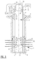
Figure 1 is a schematic longitudinal sectional view of a wet gas production well in which a well cleaning plunger has been lowered to the bottom of the well; -
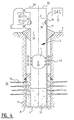
Figure 2 is a schematic longitudinal sectional view of the wet gas production well ofFigure 1 during an unloading phase wherein the well cleaning plunger is pushed towards the wellhead and thereby lifts solid and liquid well deposits from the well; -
Figure 3 is a schematic longitudinal sectional view of the wet gas production well ofFigures 1 and2 during an afterflow phase wherein the well cleaning plunger is located in a lubricator within the wellhead assembly; and -
Figure 4 is a schematic longitudinal sectional view of the wet gas production well ofFigures 1-3 during a shut-in phase wherein production is interrupted to allow the cleaning plunger to descend back from the wellhead to the bottom of the well. -
Figures 1-4 show a hydrocarbon fluid production well that is cleaned by a plunger lift well cleaning operation wherein aplunger 1 is moved up and down through aproduction tubing 2 within thewellbore 3 to lift liquid and solid deposits 4 to hydrocarbon fluid processing facilities (not shown) at the earth surface 5. - In
Figure 1 theplunger 1 is located at thebottom 6 of thewellbore 3 below a perforated welleffluent influx zone 7 in which theperforations 15 have been shot through theproduction tubing 2, and through thegravel pack 8, the well casing or liner 9 and the surroundinghydrocarbon bearing formation 10 to permit influx, as illustrated byarrows 11 of a multiphase mixture of well effluents comprising natural gas and solid and/or liquid components, such as water, condensates, wax, asphaltenes and/or other precipitates and/or formation particles, such as rock, sand and/or clay particles, flow into theproduction tubing 2. - At least a fraction of the solid and/or liquid components may be dragged by the flux of natural gas illustrated by
arrows 11 to thewellhead 12 and at least another fraction of the solid and/or liquid components may accumulate in a gradually increasingpool 13 of well deposits through which natural gas bubbles 14 travel in upward direction as illustrated byarrows 11. - A fiber optical Distributed Vibration Sensing (DVS)
cable 16 is bonded to the outer surface of theproduction tubing 2 and is connected to aDVS interrogation assembly 17, which is configured to monitor vibrations resulting from acoustic and/or thermal events within thewellbore 3, such as the noise generated by the flux of natural gas bubbles 14 through thepool 13 of well deposits. - If the
DVS interrogation assembly 17 indicates that the level of thepool 13 of well deposit reaches a level at which production of natural gas is inhibited then theproduction choke 31 may be fully opened so that the well effluents drag theplunger 1 to surface. -
Figure 2 shows the well onloading phase during which the thus releasedplunger 1 is further pushed up, as illustrated by arrow 20, by the flux of welleffluents 11 through theproduction tubing 2 and thereby also pushes thepool 13 of well deposits up towards thewellhead 12. - The
plunger 1 may or may not be equipped withfins 21 that may not fully seal off the annular space between theplunger 1 and the inner surface of theproduction tubing 2, so that a residual fraction of the produced natural gas still migrates asgas bubbles 14 through the annular space and the pool ofwell deposits 13 above the plunger, thereby allowing theDVS interrogation assembly 17 to monitor the upward migration and size of the pool ofwell deposits 13 as it is pushed by theplunger 1 towards thewellhead 12. - The
DVS interrogation assembly 17 is also configured to monitor acoustic events associated with the upward movement of theplunger 1 through theproduction tubing 2, such as the scratching of thefins 21 and/or other parts of the outer surface of theplunger 1 along the inner surface and/or tubing joints of theproduction tubing 2, and/or whistling noise generated by the residual fraction of natural gas flowing through any remaining gaps between thefins 21 and/or other parts of the outer surface of theplunger 1 and the inner surface of theproduction tubing 2. -
Figure 3 shows the well during an afterflow phase during which theplunger 1 is located within alubricator 30 in thewellhead assembly 12.
When theplunger 1 reaches thewellhead assembly 12 there is the risk that its upward velocity is too high and that theplunger 1 andwellhead assembly 12 are damaged by the impact of the collision between theplunger 1 andwellhead assembly 12. - To avoid such collision and associated damage the
DVS interrogation assembly 17 monitors the position and upward velocity of theplunger 1 and induces, if the upward velocity of the plunger is too high when it approaches thewellhead assembly 12, a gradual closing of theproduction choke 31 and/orbypass valve 32 at thewellhead outlet conduits plunger 1. - Once the
plunger 1 is located within thelubricator 30 in thewellhead assembly 12 thebypass valve 32 and alubricator valve 36 are closed, so that thelubricator 30 is isolated from thewellbore 3 and may be opened to retrieve theplunger 1 from the well for maintenance, inspection or replacement wherein theplunger 1 may be cleaned,worn fins 21 may be replaced and/or a spring and/or bladder actuated plunger release mechanism may be re-activated. - During the afterflow phase production of well effluents is continued and a
pool 13 of well deposits starts again to accumulate at thebottom 6 of the well. When theupper level 37 of thepool 13 reaches thelower perforations 15 gas bubbles will migrate through thepool 13, and the associated noise will be detected by theDVS interrogation assembly 17. - After such detection the
production choke 31 is closed and thelubricator valve 36 is opened to allow theplunger 1 to be lowered by gravity forces to thebottom 6 of thewellbore 3 as illustrated inFigure 4 . - When the
plunger 1 descends through thewellbore 3noise 40 will be generated by friction between thefins 21 and/or other parts of the outer surface of theplunger 1 and the inner surface of thetubing 3 tubing joints and/orperforations 15. Thisnoise 40 is monitored by the fiberoptical DVS cable 16 and associatedDVS interrogation assembly 17, so that the position and downward motion of theplunger 1 are accurately monitored. Once theDVS interrogation assembly 17 indicates that theplunger 1 reaches thebottom 6 of thewellbore 3 the production choke 31 orbypass valve 32 is opened so that well effluent production is re-started and the produced well effluents drag theplunger 1 to surface. - The
plunger 1 may be equipped with an acoustic source, such as a whistle and/or battery powered microphone that transmits anoise 40 that can be accurately monitored by the fiberoptical DVS cable 16 and associatedDVS interrogation assembly 17. - It will be understood that a skilled person may identify other features, embodiments and advantages of the method and system according to the present invention that are not identified in this specification. For example, the DVS cable may be embedded in a cement annulus surrounding the well casing or liner 9 instead of an annular space between the
production tubing 2 and well casing or liner 9. - It will also be understood that a skilled person may make modifications to the fiber optical DVS plunger lift monitoring method and system according to the invention that do not go beyond the inventive concept described herein and that the non-limiting examples described with reference to the accompanying drawings therefore do not limit the scope of the accompanying claims.
Claims (15)
- A method for monitoring well effluent plunger lift operations wherein well effluent deposits are removed from a hydrocarbon fluid production well by a plunger that cyclically moves up and down through the wellbore, the method comprising:- arranging a fiber optical Distributed Vibration Sensing(DVS) assembly along at least part of the length of the wellbore; and- inducing the fiber optical DVS assembly to record vibrations indicative of at least one of the following vibration triggering events:a) a motion and/or position of the plunger within the wellbore;b) a motion of the plunger along an irregular surface, such as a curvature and/or a joint between a pair of adjacent well tubulars;c) an approach or arrival of the plunger at a bottom or a wellhead of the wellbore;d) a motion of the hydrocarbon fluid and/or well effluent deposits through the wellbore;e) a motion of the hydrocarbon fluid through an accumulation of the well effluent deposits in the wellbore;f) a motion of the hydrocarbon fluid through an accumulation of the well effluent deposits in a well effluent inflow region at the bottom of the wellbore;g) a motion of the hydrocarbon fluid through an annular space between the plunger and the wellbore;h) a motion of the hydrocarbon fluid passing from the annular space between the plunger and the wellbore through an accumulation of the well effluent deposits above the plunger;i) a variation and/or interruption of motion of the hydrocarbon fluid and/or of the well effluent deposits in the annular space and/or other parts of the well;and/orj) a temperature difference between the well effluent deposits, the produced hydrocarbon fluid and/or the plunger.
- The method of claim 1, wherein the method further comprises optimizing the plunger lift operation and associated production of hydrocarbon fluid and well deposits in response to the vibrations recorded by the fiber optical Distributed Vibration Sensing (DVS)assembly relating to at least one of the vibration triggering events (a)-(j).
- The method of claim 2, wherein the hydrocarbon production well is a natural gas production well and the fiber optical Distributed Vibration Sensing(DVS) assembly comprises an optical fiber which extends along at least a substantial part of length of the wellbore, and is in acoustic contact with, an outer surface of a production tubing through which a multiphase well effluent mixture comprising natural gas and at least some liquid, viscous and/or solid well effluent components, such as water, condensates, wax, asphaltenes, precipitates and/or solid particles, are produced, and the plunger moves cyclically up and down through the production tubing to remove any well effluent deposits comprising the liquid, viscous and/or solid components from the interior of the production tubing.
- The method of claim 3, wherein the production tubing comprises a permeable inflow region above a bottom of the well and the wellhead comprises a lubricator located above a well effluent outlet provided with a production choke and the plunger is cyclically moved up and down between the bottom of the well and the lubricator.
- The method of claim 4, wherein the cyclic motion of the plunger comprises the following phases:- an unloading phase during which the plunger is pushed in upward direction through the production tubing towards the wellhead by the pressure of the well effluents in the section of the production tubing below the plunger;- an afterflow phase during which the plunger is located in the lubricator above the well effluent outlet, while well effluents are produced through the well effluent outlet; and- a shut-in phase during which production of well effluents is interrupted and the plunger is released from the lubricator and is allowed to descend through the production tubing to the bottom of the well.
- The method of claim 5, wherein at least during at least part of the unloading phase the production of well effluents is controlled by varying the opening of the production choke in response to information provided by the DVS assembly about the location and upward velocity of the plunger through the production tubing.
- The method of claim 6, wherein the production choke is gradually at least partially closed if the DVS assembly indicates that the plunger reaches an upper part of the production tubing in the vicinity of the wellhead, thereby reducing the velocity of the plunger as it enters the wellhead and lubricator.
- The method of claim 7, wherein the fiber optical Distributed Vibration Sensing (DVS) assembly is configured to monitor a location of a liquid-gas interface above a deposition of well effluents in the production tubing by monitoring noise associated by migration of natural gas through the deposition and the thus monitored location of the liquid-gas interface is subsequently used as an input to a production choke control system to control the position of the production choke and the position and movement of the plunger within the production tubing, and/or to optimize the liquid unloading phase of the well, and/or a duration of the after-flow phase during which the plunger is arranged in a surface lubricator in the wellhead above the production choke and and/or a duration of the shut-in phase during which the production choke is closed and the plunger is lowered from the wellhead to a bottom of the well.
- The method of any one of claims 1-8, wherein the plunger comprises an acoustic source that transmits an acoustic noise that is detected by the fiber optical Distributed Vibration Sensing (DVS) assembly.
- A system for monitoring well effluent plunger lift operations wherein well effluent deposits are removed from a hydrocarbon fluid production well by a plunger that cyclically moves up and down through the wellbore, the system comprising:- a fiber optical Distributed Vibration Sensing(DVS) assembly arranged along at least part of the length of the wellbore, which fiber optical DVAS assembly is configured to record vibrations indicative of at least one of the following vibration triggering events:a) a motion and/or position of the plunger within the wellbore;b) a motion of the plunger along an irregular surface, such as a curvature and/or a joint between a pair of adjacent well tubulars;c) an approach or arrival of the plunger at a bottom or a wellhead of the wellbore;d) a motion of the hydrocarbon fluid and/or well effluent deposits through the wellbore;e) a motion of the hydrocarbon fluid through an accumulation of the well effluent deposits in the wellbore;f) a motion of the hydrocarbon fluid through an accumulation of the well effluent deposits in a well effluent inflow region at the bottom of the wellbore;g) a motion of the hydrocarbon fluid through an annular space between the plunger and the wellbore;h) a motion of the hydrocarbon fluid passing from the annular space between the plunger and the wellbore through an accumulation of the well effluent deposits above the plunger;i) a variation and/or interruption of motion of the hydrocarbon fluid and/or of the well effluent deposits in the annular space and/or other parts of the well;and/orj) a temperature difference between the well effluent deposits, the produced hydrocarbon fluid and/or the plunger.
- The system of claim 10, wherein the system further comprises means for optimizing the plunger lift operation and associated production of hydrocarbon fluid and well deposits in response to the acoustic signals recorded by the fiber optical Distributed Vibration Sensing (DVS)assembly relating to at least one of the acoustic signal triggering events (a)-(j).
- The system of claim 11, wherein the hydrocarbon production well is a natural gas production well and the fiber optical Distributed Vibration Sensing(DVS) assembly comprises an optical fiber which extends along at least a substantial part of length of the wellbore, and is in acoustic contact with, an outer surface of a production tubing through which a multiphase well effluent mixture comprising natural gas and at least some liquid, viscous and/or solid well effluent components, such as water, condensates, wax, asphaltenes, precipitates and/or solid particles, are produced, and the plunger moves cyclically up and down through the production tubing to remove any well effluent deposits comprising the liquid, viscous and/or solid components from the interior of the production tubing.
- The system of any one of claims 10-12, wherein the plunger comprises an acoustic source that is configured to transmit an acoustic noise that is detectable by the fiber optical Distributed Vibration Sensing (DVS) assembly.
- The system of any one of claims 10-13, wherein the Distributed Vibration Sensing (DVS) assembly is configured to monitor acoustic events with frequencies of less than 50 Hz, optionally frequencies of less than 20 Hz.
- The system of claim 14, wherein the DVS is configured to monitor acoustic events with frequencies below 10 Hz.
Priority Applications (2)
| Application Number | Priority Date | Filing Date | Title |
|---|---|---|---|
| EP14156297.5A EP2910731A1 (en) | 2014-02-24 | 2014-02-24 | Monitoring well effluent plunger lift operations |
| PCT/US2015/017020 WO2015127336A1 (en) | 2014-02-24 | 2015-02-23 | Monitoring well effluent plunger lift operations |
Applications Claiming Priority (1)
| Application Number | Priority Date | Filing Date | Title |
|---|---|---|---|
| EP14156297.5A EP2910731A1 (en) | 2014-02-24 | 2014-02-24 | Monitoring well effluent plunger lift operations |
Publications (1)
| Publication Number | Publication Date |
|---|---|
| EP2910731A1 true EP2910731A1 (en) | 2015-08-26 |
Family
ID=50150656
Family Applications (1)
| Application Number | Title | Priority Date | Filing Date |
|---|---|---|---|
| EP14156297.5A Pending EP2910731A1 (en) | 2014-02-24 | 2014-02-24 | Monitoring well effluent plunger lift operations |
Country Status (2)
| Country | Link |
|---|---|
| EP (1) | EP2910731A1 (en) |
| WO (1) | WO2015127336A1 (en) |
Cited By (3)
| Publication number | Priority date | Publication date | Assignee | Title |
|---|---|---|---|---|
| EP3532704A4 (en) * | 2016-10-29 | 2020-06-10 | Kelvin Inc. | ESTIMATION AND OPTIMIZATION OF PLUNGER PISTON PUMP CONDITIONS USING ACOUSTIC DATA |
| CN112504430A (en) * | 2020-11-26 | 2021-03-16 | 南京大学 | Tower structure health monitoring method based on vibration sensitive optical fiber sensing technology |
| CN118520401A (en) * | 2024-07-19 | 2024-08-20 | 陕西天和乳业有限公司 | Dairy product production monitoring system based on data processing |
Citations (12)
| Publication number | Priority date | Publication date | Assignee | Title |
|---|---|---|---|---|
| US20020074118A1 (en) | 2000-10-06 | 2002-06-20 | Danny Fisher | Auto adjusting well control system |
| US20020084071A1 (en) * | 2000-10-31 | 2002-07-04 | Mccoy James N. | Determination of plunger location and well performance parameters in a borehole plunger lift system |
| US20040129428A1 (en) | 2002-12-20 | 2004-07-08 | Kelley Terry Earl | Plunger lift deliquefying system for increased recovery from oil and gas wells |
| US20070261845A1 (en) | 2006-04-03 | 2007-11-15 | Time Products, Inc. | Methods and apparatus for enhanced production of plunger lift wells |
| US20080164024A1 (en) | 2006-12-18 | 2008-07-10 | Giacomino Jeffrey L | Method and Apparatus for Utilizing Pressure Signature in Conjunction with Fall Time As Indicator in Oil and Gas Wells |
| US20080202746A1 (en) | 2007-02-28 | 2008-08-28 | Vinson Process Controls Company, L.P. | Plunger Lift Controller and Method |
| US20090200020A1 (en) | 2005-07-13 | 2009-08-13 | William Hearn | Methods and apparatus for optimizing well production |
| US20100207019A1 (en) * | 2009-02-17 | 2010-08-19 | Schlumberger Technology Corporation | Optical monitoring of fluid flow |
| US20110088462A1 (en) * | 2009-10-21 | 2011-04-21 | Halliburton Energy Services, Inc. | Downhole monitoring with distributed acoustic/vibration, strain and/or density sensing |
| US20120092960A1 (en) * | 2010-10-19 | 2012-04-19 | Graham Gaston | Monitoring using distributed acoustic sensing (das) technology |
| US20120193091A1 (en) | 2005-02-24 | 2012-08-02 | Bender Robert E | Plunger lift control system arrangement |
| US20130167628A1 (en) * | 2007-02-15 | 2013-07-04 | Hifi Engineering Inc. | Method and apparatus for detecting an acoustic event along a channel |
Family Cites Families (1)
| Publication number | Priority date | Publication date | Assignee | Title |
|---|---|---|---|---|
| US9181768B2 (en) | 2011-06-15 | 2015-11-10 | Pcs Ferguson, Inc. | Method and apparatus for detecting plunger arrival |
-
2014
- 2014-02-24 EP EP14156297.5A patent/EP2910731A1/en active Pending
-
2015
- 2015-02-23 WO PCT/US2015/017020 patent/WO2015127336A1/en not_active Ceased
Patent Citations (13)
| Publication number | Priority date | Publication date | Assignee | Title |
|---|---|---|---|---|
| US20020074118A1 (en) | 2000-10-06 | 2002-06-20 | Danny Fisher | Auto adjusting well control system |
| US20020084071A1 (en) * | 2000-10-31 | 2002-07-04 | Mccoy James N. | Determination of plunger location and well performance parameters in a borehole plunger lift system |
| US6634426B2 (en) | 2000-10-31 | 2003-10-21 | James N. McCoy | Determination of plunger location and well performance parameters in a borehole plunger lift system |
| US20040129428A1 (en) | 2002-12-20 | 2004-07-08 | Kelley Terry Earl | Plunger lift deliquefying system for increased recovery from oil and gas wells |
| US20120193091A1 (en) | 2005-02-24 | 2012-08-02 | Bender Robert E | Plunger lift control system arrangement |
| US20090200020A1 (en) | 2005-07-13 | 2009-08-13 | William Hearn | Methods and apparatus for optimizing well production |
| US20070261845A1 (en) | 2006-04-03 | 2007-11-15 | Time Products, Inc. | Methods and apparatus for enhanced production of plunger lift wells |
| US20080164024A1 (en) | 2006-12-18 | 2008-07-10 | Giacomino Jeffrey L | Method and Apparatus for Utilizing Pressure Signature in Conjunction with Fall Time As Indicator in Oil and Gas Wells |
| US20130167628A1 (en) * | 2007-02-15 | 2013-07-04 | Hifi Engineering Inc. | Method and apparatus for detecting an acoustic event along a channel |
| US20080202746A1 (en) | 2007-02-28 | 2008-08-28 | Vinson Process Controls Company, L.P. | Plunger Lift Controller and Method |
| US20100207019A1 (en) * | 2009-02-17 | 2010-08-19 | Schlumberger Technology Corporation | Optical monitoring of fluid flow |
| US20110088462A1 (en) * | 2009-10-21 | 2011-04-21 | Halliburton Energy Services, Inc. | Downhole monitoring with distributed acoustic/vibration, strain and/or density sensing |
| US20120092960A1 (en) * | 2010-10-19 | 2012-04-19 | Graham Gaston | Monitoring using distributed acoustic sensing (das) technology |
Non-Patent Citations (3)
| Title |
|---|
| HALLIBURTON: "Artificial Lift systems and the 5P's", 14 November 2012 (2012-11-14), pages 1 - 6, XP007922645, Retrieved from the Internet <URL:http://halliburtonblog.com/artificial-lift-and-the-5-ps/> [retrieved on 20140415] * |
| HALLIBURTON: "Fiberwatch services", 31 December 2012 (2012-12-31), pages 1 - 2, XP007922646, Retrieved from the Internet <URL:http://www.halliburton.com/public/pe/contents/Data_Sheets/web/H/H07778.pdf> [retrieved on 20140415] * |
| J MCCOY; L ROWLAN: "Plunger-lift optimization by monitoring and analyzing well high frequency acoustic signals, tubing pressure and casing pressure", SPE PAPER 71083, May 2001 (2001-05-01) |
Cited By (4)
| Publication number | Priority date | Publication date | Assignee | Title |
|---|---|---|---|---|
| EP3532704A4 (en) * | 2016-10-29 | 2020-06-10 | Kelvin Inc. | ESTIMATION AND OPTIMIZATION OF PLUNGER PISTON PUMP CONDITIONS USING ACOUSTIC DATA |
| US10883491B2 (en) | 2016-10-29 | 2021-01-05 | Kelvin Inc. | Plunger lift state estimation and optimization using acoustic data |
| CN112504430A (en) * | 2020-11-26 | 2021-03-16 | 南京大学 | Tower structure health monitoring method based on vibration sensitive optical fiber sensing technology |
| CN118520401A (en) * | 2024-07-19 | 2024-08-20 | 陕西天和乳业有限公司 | Dairy product production monitoring system based on data processing |
Also Published As
| Publication number | Publication date |
|---|---|
| WO2015127336A1 (en) | 2015-08-27 |
Similar Documents
| Publication | Publication Date | Title |
|---|---|---|
| RU2562295C2 (en) | System and methods for detection and monitoring of erosion | |
| CN110168191B (en) | Methods of plugging and pressure testing wells | |
| US8899339B2 (en) | Systems and methods for regulating flow in a wellbore | |
| CN103154426B (en) | Use the method that sliding-sleeve valve assembly carries out multilamellar producing well completion | |
| US10689971B2 (en) | Bridge plug sensor for bottom-hole measurements | |
| JP2019178602A (en) | Method and device for obtaining measurements of downhole properties in a subterranean well | |
| CA2913882C (en) | Closed loop deployment of a work string including a composite plug in a wellbore | |
| US8706463B2 (en) | System and method for completion optimization | |
| US20120046866A1 (en) | Oilfield applications for distributed vibration sensing technology | |
| US10519761B2 (en) | System and methodology for monitoring in a borehole | |
| AU2014315152B2 (en) | Method and system for monitoring fluid flux in a well | |
| US11339627B2 (en) | Method of establishing a cement plug in an annular region between a first and a second casing | |
| US20080164024A1 (en) | Method and Apparatus for Utilizing Pressure Signature in Conjunction with Fall Time As Indicator in Oil and Gas Wells | |
| WO2015127336A1 (en) | Monitoring well effluent plunger lift operations | |
| EP2964873B1 (en) | Wireline assisted coiled tubing portion and method for operation of such a coiled tubing portion | |
| WO2015005998A1 (en) | Well fluid treatment apparatus | |
| US11248432B2 (en) | Method and apparatus for suspending a well | |
| EP2823140B1 (en) | Method for zone isolation in a subterranean well | |
| Dale et al. | A case history of reservoir subsidence and wellbore damage management in the South Belridge diatomite field | |
| Richard | Sand & fines in multiphase oil and gas production | |
| GB2561120A (en) | Method of plugging and pressure testing a well |
Legal Events
| Date | Code | Title | Description |
|---|---|---|---|
| PUAI | Public reference made under article 153(3) epc to a published international application that has entered the european phase |
Free format text: ORIGINAL CODE: 0009012 |
|
| STAA | Information on the status of an ep patent application or granted ep patent |
Free format text: STATUS: THE APPLICATION HAS BEEN PUBLISHED |
|
| AK | Designated contracting states |
Kind code of ref document: A1 Designated state(s): AL AT BE BG CH CY CZ DE DK EE ES FI FR GB GR HR HU IE IS IT LI LT LU LV MC MK MT NL NO PL PT RO RS SE SI SK SM TR |
|
| AX | Request for extension of the european patent |
Extension state: BA ME |