EP2910684A1 - Pneumatic fender - Google Patents
Pneumatic fender Download PDFInfo
- Publication number
- EP2910684A1 EP2910684A1 EP13844770.1A EP13844770A EP2910684A1 EP 2910684 A1 EP2910684 A1 EP 2910684A1 EP 13844770 A EP13844770 A EP 13844770A EP 2910684 A1 EP2910684 A1 EP 2910684A1
- Authority
- EP
- European Patent Office
- Prior art keywords
- hollow body
- flexible hollow
- casing
- inner space
- pneumatic fender
- Prior art date
- Legal status (The legal status is an assumption and is not a legal conclusion. Google has not performed a legal analysis and makes no representation as to the accuracy of the status listed.)
- Granted
Links
- 238000004891 communication Methods 0.000 claims abstract description 9
- 230000006835 compression Effects 0.000 claims description 49
- 238000007906 compression Methods 0.000 claims description 49
- 238000004873 anchoring Methods 0.000 claims description 10
- 230000000694 effects Effects 0.000 abstract description 7
- 238000010521 absorption reaction Methods 0.000 description 8
- 238000007789 sealing Methods 0.000 description 7
- XEEYBQQBJWHFJM-UHFFFAOYSA-N Iron Chemical compound [Fe] XEEYBQQBJWHFJM-UHFFFAOYSA-N 0.000 description 4
- 230000002159 abnormal effect Effects 0.000 description 4
- 238000004519 manufacturing process Methods 0.000 description 4
- 230000003014 reinforcing effect Effects 0.000 description 4
- 230000002093 peripheral effect Effects 0.000 description 3
- 229910000831 Steel Inorganic materials 0.000 description 2
- 229910052742 iron Inorganic materials 0.000 description 2
- 239000000463 material Substances 0.000 description 2
- 238000000034 method Methods 0.000 description 2
- 239000000203 mixture Substances 0.000 description 2
- 230000007935 neutral effect Effects 0.000 description 2
- 239000010959 steel Substances 0.000 description 2
- 230000008961 swelling Effects 0.000 description 2
Images




Classifications
-
- E—FIXED CONSTRUCTIONS
- E02—HYDRAULIC ENGINEERING; FOUNDATIONS; SOIL SHIFTING
- E02B—HYDRAULIC ENGINEERING
- E02B3/00—Engineering works in connection with control or use of streams, rivers, coasts, or other marine sites; Sealings or joints for engineering works in general
- E02B3/20—Equipment for shipping on coasts, in harbours or on other fixed marine structures, e.g. bollards
- E02B3/26—Fenders
-
- B—PERFORMING OPERATIONS; TRANSPORTING
- B63—SHIPS OR OTHER WATERBORNE VESSELS; RELATED EQUIPMENT
- B63B—SHIPS OR OTHER WATERBORNE VESSELS; EQUIPMENT FOR SHIPPING
- B63B59/00—Hull protection specially adapted for vessels; Cleaning devices specially adapted for vessels
- B63B59/02—Fenders integral with waterborne vessels or specially adapted therefor, e.g. fenders forming part of the hull or incorporated in the hull; Rubbing-strakes
- B63B2059/025—Fenders integral with waterborne vessels or specially adapted therefor, e.g. fenders forming part of the hull or incorporated in the hull; Rubbing-strakes pneumatic, e.g. inflatable
-
- Y—GENERAL TAGGING OF NEW TECHNOLOGICAL DEVELOPMENTS; GENERAL TAGGING OF CROSS-SECTIONAL TECHNOLOGIES SPANNING OVER SEVERAL SECTIONS OF THE IPC; TECHNICAL SUBJECTS COVERED BY FORMER USPC CROSS-REFERENCE ART COLLECTIONS [XRACs] AND DIGESTS
- Y02—TECHNOLOGIES OR APPLICATIONS FOR MITIGATION OR ADAPTATION AGAINST CLIMATE CHANGE
- Y02A—TECHNOLOGIES FOR ADAPTATION TO CLIMATE CHANGE
- Y02A30/00—Adapting or protecting infrastructure or their operation
- Y02A30/30—Adapting or protecting infrastructure or their operation in transportation, e.g. on roads, waterways or railways
Definitions
- the present invention relates to a pneumatic fender, and, more specifically, to a pneumatic fender that suppresses damage to a flexible hollow body and an energy-absorbing body and exhibits improved ship sway reduction effects.
- pneumatic fender is a pneumatic fender comprising a flexible hollow body provided between two mounting plates.
- the flexible hollow body is formed from rubber in which a reinforcing layer is embedded, and is connected to the mounting plates in an airtight manner.
- a rear surface side of one mounting plate is mounted to a quay or the like, and a front side of the other of the mounting plates contacts a ship via a shock-receiving plate.
- the flexible hollow body is compressed when the ship contacts the shock-receiving plate, causing the energy from the ship to be absorbed.
- an excessive amount of energy is imparted by the ship, such as when the ship forcefully collides with the shock-receiving plate, the flexible hollow body may be excessively compressed, causing damage thereto.
- a pneumatic fender in which a honeycomb-structured energy-absorbing body is provided within a flexible hollow body has been proposed (see Patent Document 1).
- the mounting plate on the front side contacts the energy-absorbing body and absorbs the energy from the ship before the flexible hollow body is excessively compressed, thereby allowing for a reduction in disadvantages such as damage to the flexible hollow body due to excess compression.
- the energy-absorbing body is deformed and damaged by absorbing energy, it will cease functioning as an energy-absorbing body if the degree of damage is too great, requiring the pneumatic fender to be replaced.
- Patent Document 1 Japanese Unexamined Patent Application Publication No. H11-152728A
- An object of the present invention is to provide a pneumatic fender that suppresses damage to a flexible hollow body and an energy-absorbing body and exhibits improved ship sway reduction effects.
- a pneumatic fender is a pneumatic fender comprising a flexible hollow body provided between facing mounting plates, the fender comprising: an orifice that allows for communication between an interior space of the flexible hollow body and an interior space of a rigid casing that is provided on a surface of one of the mounting plates; and a safety valve that opens and allows for communication between the interior space of the flexible hollow body and the interior space of the casing by opening when the internal pressure of the flexible hollow body reaches a predetermined pressure.
- the safety valve opens when the internal pressure of the flexible hollow body reaches a predetermined pressure, allowing for communication between the interior space of the flexible hollow body and the interior space of the casing via the safety valve; thus, when the internal pressure of the flexible hollow body reaches a certain degree, air can flow into the inner space of the casing, suppressing increases in the internal pressure of the flexible hollow body. Damage to the flexible hollow body due to excessive compression can thus be suppressed.
- the flexible hollow body is thus restored to its pre-compression state, allowing for repeated use over extended periods of time without causing damage to the casing functioning as an energy-absorbing body.
- the flexible hollow body is restored to its pre-compression state at a slow speed, reducing the counter force produced by this restoration. As a result, swaying of the ship contacting the pneumatic fender during this restoration can be further reduced.
- the pneumatic fender 1 according to the present invention illustrated in FIG. 1 (hereinafter, referred to as "the fender 1") is provided with a mounting plate 2a, a mounting plate 2b, and a flexible hollow body 4.
- the one mounting plate 2a is mounted on a quay 11 or the like, and a shock-receiving plate 3 is mounted on a front side of the other mounting plate 2b.
- the shock-receiving plate 3 contacts a side of a ship or the like.
- the flexible hollow body 4 is interposed between the mounting plate 2a and the mounting plate 2b and is joined to the mounting plates 2a, 2b in an airtight manner.
- the flexible hollow body 4 has a cylindrical shape provided with flanges 4a on both ends, and is constituted by rubber 5 in which a reinforcing layer 6 has been embedded.
- the spacing H between the mounting plate 2a and the mounting plate 2b, i.e., the height dimension of the flexible hollow body 4 is set on the basis of the energy absorption performance and the like required for the fender 1.
- a casing 7 having a projection height h is provided on a surface of the one mounting plate 2a positioned within the interior of the flexible hollow body 4, and is disposed within an inner space 4A of the flexible hollow body 4.
- the casing 7 is a rigid structure formed from a rigid material such as steel or iron. The casing 7 prevents damage caused by excess compression of the flexible hollow body 4.
- the casing 7 can also be disposed projecting from a surface of the other mounting plate 2b within the inner space 4A of the flexible hollow body 4. If the casing 7 is mounted on the other mounting plate 2b, the weight of the casing 7 acts upon the flexible hollow body 4, which is cantileveringly disposed with respect to the quay 11. Thus, it is preferable to mount the casing 7 to the one mounting plate 2a anchored to the quay 11 in order to eliminate the load applied to the flexible hollow body 4 by the weight of the casing 7.
- the casing 7 is provided with an orifice 10 and a safety valve 8.
- the orifice 10 allows for communication between the space outside the casing 7 within the interior space 4A of the flexible hollow body 4 and an interior space 7A of the casing 7.
- a small hole (having, for example, an opening area of about 0.5 mm 2 to 80 mm 2 or an opening diameter of about 1 mm to 10 mm) formed in a wall of the casing 7 can be used as the orifice 10.
- the orifice 10 is not limited to being a small hole; any structure that yields the same effects as a small hole can be used. There is no particular limitation upon the number of orifices 10, but it is preferable to provide a plurality thereof as they can conceivably become blocked for various reasons.
- the safety valve 8 opens when the internal pressure P of the flexible hollow body 4 (i.e., the pressure of the space within the inner space 4A and outside the casing 7) reaches a predetermined pressure P1.
- the space in the inner space 4A outside the casing 7 and the inner space 7A of the casing 7 communicate through the open safety valve 8.
- the safety valve 8 of the present embodiment is constituted by a through-hole 9a formed in a wall of the casing 7, a valve body 9b, a biasing member 9c such as a spring, and a sealing member 9d.
- the valve body 9b is biased by the biasing member 9c toward the wall in which the through-hole 9a is formed.
- the sealing member 9d which is mounted to the valve body 9b, is compression bonded to the wall so as to surround the periphery of the through-hole 9a, thereby closing the safety valve 8 closes to block the through-hole 9a.
- the safety valve 8 is not limited to the structure described in the present embodiment; any structure in which the safety valve 8 opens when the internal pressure P of the flexible hollow body 4 reaches the predetermined pressure P1 is acceptable.
- the shock-receiving plate 3 of the fender 1 When a ship contacts the shock-receiving plate 3 of the fender 1 in the state illustrated in FIG. 1 , in which the flexible hollow body 4 is not compressed, the shock-receiving plate 3 is pressed down, as illustrated in FIG. 2 , and the flexible hollow body 4 enters a compressed state.
- the casing 7 of the fender 1 is disposed within the inner space 4A of the flexible hollow body 4; thus, the initial pre-compression volume of the flexible hollow body 4 is that of the inner space 4A less the volume of the casing 7.
- Increased counter force R is advantageous in preventing damage as it impedes the flexible hollow body 4 to be excessively compressed.
- the flexible hollow body 4 As illustrated in FIGS. 3 and 4 , as the shock-receiving plate 3 is further pressed down, the flexible hollow body 4 is further compressed, and, when the internal pressure P of the flexible hollow body 4 reaches the predetermined pressure P1, the valve body 9b upon which the predetermined pressure P1 has been placed moves against the biasing force of the biasing member 9c in a direction away from the wall in which the through-hole 9a is formed. As a result, the sealing member 9d moves away from the wall and the safety valve 8 opens.
- the predetermined pressure P1 at which the safety valve 8 opens is set, for example, to about 20% to 90% of the rated withstand pressure of the fender 1.
- Rated withstand pressure is the internal pressure of the flexible hollow body 4 when the flexible hollow body 4 is compressed at a maximum compression rate, to be described below.
- the air A that has flowed into the inner space 7A of the casing 7 is gradually expelled through the orifice 10 to the inner space 4A of the flexible hollow body 4 outside of the casing 7.
- the expulsion of the air A from the inner space 7A of the casing 7 restores the flexible hollow body 4 to its pre-compression state.
- the casing 7 is made to function as an energy-absorbing body without being damaged, allowing for repeated use over extended periods of time.
- the flexible hollow body 4 can also be used repeatedly over extended periods of time without damage.
- the orifice 10 through which the air A is expelled from the inner space 7A of the casing 7 is a small hole, the speed at which the flexible hollow body 4 is restored to its pre-compression state is reduced. This reduces the counter force R produced by this restoration, allowing for further reduction in swaying of the ship in contact with the shock-receiving plate 3 during the restoration process.
- the total opening area of the plurality of orifices 10 is selected as appropriate; for example, the total opening area of the total orifices 10 is set to 1% to 30%, preferably 2% to 15%, of the area of the wall of the casing 7.
- This causes the flexible hollow body 4 to be gradually compressed when the ship berths at a low speed, which in turn ensures that the diameter and total area of the orifices 10 are suitably large with respect to the increase in the pressure in the inner space 4A and the pressure is equalized between the inner space 4A and the inner space 7A of the casing 7, thus eliminating the effects of the casing 7 and allowing the berthing energy of the ship to be absorbed at the soft counter force initially possessed by the fender 1.
- the flexible hollow body 4 is dynamically compressed, causing the diameter and total opening area of the orifices 10 to be sufficiently small with respect to increases in the pressure in the inner space 4A and the volume of the flexible hollow body 4 to become that of the inner space 4A less the volume of the casing 7, allowing for increased counter force R.
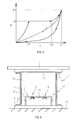
- FIG. 5 schematically shows the relationship between compression level X and counter force R in one cycle of the flexible hollow body 4 being compressed and restored.
- the solid lines represent the fender 1 of the present embodiment
- the single-dashed lines represent a conventional fender in which a casing 7 is not disposed within the inner space 4A of the flexible hollow body 4.
- the volume of the compressed flexible hollow body 4 is less than that of a conventional fender, as described above. This allows the fender 1 to yield greater counter force R compared to the conventional fender.
- the safety valve 8 opens and air A flows into the inner space 7A of the casing 7.
- the flexible hollow body 4 remains at a generally constant internal pressure P1 until the compression level X reaches X2, suppressing increases in internal pressure and yielding a generally constant counter force R1 for the counter force R.
- the flexible hollow body 4 When the flexible hollow body 4 is further compressed so that the compression level X reaches X2, and the inflowing air A causes the pressure in the inner space 7A to become equal to the internal pressure of the flexible hollow body 4, the counter force R increases. After the flexible hollow body 4 has been compressed to the point that counter force R2 is reached, the flexible hollow body 4 is restored to its pre-compression state when the compression is released. The restoration occurs at a slow speed as described above, thereby reducing the counter force R. This is advantageous in reducing ship swaying compared to a conventional fender.
- the projection height h of the casing 7 it is preferable to set the projection height h of the casing 7 to 40% or less of the spacing H between the mounting plate 2a and the mounting plate 2b, and the volume of the inner space 7A of the casing 7 to 10% to 35% of the volume of the inner space 4A of the flexible hollow body 4. This is because the casing 7 and the pressed mounting plate 2b tend to interfere with each other if the projection height h exceeds 40% of the spacing H.
- the wall of the casing 7 facing the mounting plate 2b may be in a planar shape parallel with the mounting plate 2b.
- the safety valve 8 may conceivable fail for some reason or another; thus, it is preferable to provide a plurality of valves, as illustrated in FIG. 6 .
- the plurality of safety valves 8 can all be set to open at the same predetermined pressure P1.
- at least one of the plurality of safety valves 8 can be set to open at a different predetermined pressure P1.
- the casing 7 can be divided into multiple casings as illustrated in FIG. 7 .
- the inner spaces 7A of the divided casings 7 can be set all to the same volume or to different volumes.
- the volume of the inner space 7A of a casing 7 having a safety valve 8 that opens at a low predetermined pressure P1 is less than the volume of the inner space 7A of a casing 7 having a safety valve 8 that opens at a high predetermined pressure P1 according to the energy absorption performance required for the fender 1.
- the volume of the inner space 7A of a casing 7 having a safety valve 8 that opens at a low predetermined pressure P1 is greater than the inner space 7A of a casing 7 having a safety valve 8 that opens at a high predetermined pressure P1. In this way, the pressure in the respective inner spaces 7A of the casings 7 can be controlled independently of the pressure in the other inner spaces 7A of the casings 7.
- the safety valve 8 can also have a variable-pressure structure allowing the predetermined pressure P1 at which the valve opens to be altered.
- the pressure at which the safety valve 8 opens can easily be altered by replacing the biasing member 9c with another having a different biasing force.
- Adopting a variable-pressure structure of this sort allows for various fenders 1 of different energy absorption performance to be easily manufactured simply by changing the safety valve 8. This minimizes the cost of manufacturing fenders 1 capable of handling ships of various sizes at an early stage, and is advantageous for manufacturing.
- the embodiment of a fender 1 illustrated in FIG. 8 is provided with a mounting plate 2a, a mounting plate 2b, and a flexible hollow body 4.
- the one mounting plate 2a is mounted on a quay 11 or the like
- a shock-receiving plate 3 is mounted on a front side of the other mounting plate 2b, and the side of a ship or the like contacts the shock-receiving plate 3.
- the flexible hollow body 4 is interposed between the mounting plate 2a and the mounting plate 2b and is joined to the mounting plates 2a, 2b in an airtight manner.
- the spacing H between the mounting plate 2a and the mounting plate 2b, i.e., the height dimension of the flexible hollow body 4, is set on the basis of the energy absorption performance and the like required for the fender 1.
- the flexible hollow body 4 has a cylindrical shape provided with flanges 4a on both ends, and is constituted by rubber 5 in which a reinforcing layer 6 has been embedded.
- Mounting holes 4b are formed in each of the flanges 4a at intervals along the circumferential direction.
- Anchoring members B such as bolts are embedded in the mounting holes 4b so that the heads thereof do not protrude out of the mounting holes 4b.
- Each of the flanges 4a is anchored to the mounting plates 2a, 2b by these anchoring members B.
- corner supports 4c are provided extending in an annular shape at the corners of the flanges 4a.
- the casing 7 is provided projecting from the rear surface side of the one mounting plate 2a. Specifically, the casing 7 is mounted on an outside surface of the one mounting plate 2a opposite a side in the interior of the flexible hollow body 4. In the present embodiment, the casing 7 is disposed within a space formed in the quay 11.
- the casing 7 is a rigid structure formed from a rigid material such as steel or iron.
- the mounting plate 2a is provided with an orifice 10 and a safety valve 8.
- the orifice 10 allows for communication between the inner space 4A of the flexible hollow body 4 and the interior space 7A of the casing 7.
- a small hole (having, for example, an opening area of about 0.5 mm 2 to 80 mm 2 or an opening diameter of about 1 mm to 10 mm) formed in the mounting plate 2a can be used as the orifice 10.
- the orifice 10 is not limited to being a small hole; any structure that yields the same effects as a small hole can be used. There is no particular limitation upon the number of orifices 10, but it is preferable to provide a plurality thereof as they can conceivably become blocked for various reasons.
- the safety valve 8 provided in the mounting plate 2a opens when the internal pressure P of the flexible hollow body 4 reaches the predetermined pressure P1.
- the inner space 4A and the inner space 7A of the casing 7 communicate through the open safety valve 8.
- the safety valve 8 of the present embodiment is constituted by a through-hole 9a formed in the mounting plate 2a, a valve body 9b, a biasing member 9c such as a spring, and a sealing member 9d.
- the valve body 9b is biased by the biasing member 9c toward the rear surface of the mounting plate 2a.
- the sealing member 9d which is mounted on the valve body 9b, is compression bonded to the rear surface of the mounting plate 2a so as to surround the periphery of the through-hole 9a, thereby closing the safety valve 8 to block the through-hole 9a.
- the safety valve 8 is not limited to the structure described in the present embodiment; any structure in which the safety valve 8 opens when the internal pressure P of the flexible hollow body 4 reaches the predetermined pressure P1 is acceptable.
- the flexible hollow body 4 is further compressed, and, when the internal pressure P of the flexible hollow body 4 reaches the predetermined pressure P1, the valve body 9b upon which the predetermined pressure P1 has been placed moves against the biasing force of the biasing member 9c in a direction away from the rear surface of the mounting plate 2a. As a result, the sealing member 9d moves away from the rear surface of the mounting plate 2a, and the safety valve 8 opens.
- the predetermined pressure P1 at which the safety valve 8 opens is set, for example, to about 20% to 90% of the rated withstand pressure of the fender 1.
- Rated withstand pressure is the internal pressure of the flexible hollow body 4 when the flexible hollow body 4 is compressed at a maximum compression rate, to be described below.
- the opening of the safety valve 8 causes the compressed volume when the fender 1 is pressed down to increase by the volume of the inner space 7A of the casing 7, greatly increasing energy absorption performance.
- the flexible hollow body 4 is thus capable of handling abrupt increases in the berthing energy from a ship without the need to increase the size of the flexible hollow body 4. Concomitantly, it is also possible to suppress damage to the flexible hollow body 4 caused by excessive compression.
- the safety valve 8 closes as illustrated in FIG. 12 .
- the air A that has flowed into the inner space 7A of the casing 7 gradually flows through the orifice 10 back into the inner space 4A of the flexible hollow body 4.
- the flowing back of the air A restores the flexible hollow body 4 to its pre-compression state.
- the casing 7 is made to function as an energy-absorbing body without being damaged, allowing for repeated use over extended periods of time.
- the flexible hollow body 4 can also be used repeatedly over extended periods of time without damage.
- the orifice 10 through which the air A is allowed to flow back from the inner space 7A of the casing 7 is a small hole, the speed at which the flexible hollow body 4 is restored to its pre-compression state is reduced. This reduces the counter force R produced by this restoration, allowing for further reduction in swaying of the ship in contact with the shock-receiving plate 3 during the restoration process.
- the total orifice 10 opening area is selected as appropriate; for example, the total opening area of a plurality of orifices 10 is set to 1% to 30%, preferably 2% to 15%, of the area of the mounting plate 2a within the range of the inner radius of the flexible hollow body 4.
- This causes the flexible hollow body 4 to be gradually compressed when the ship berths at a low speed, which in turn ensures that the diameter and total area of the orifices 10 are sufficiently large with respect to the increase in the pressure in the inner space 4A and the pressure is equalized between the inner space 4A and the inner space 7A of the casing 7, thus allowing the berthing energy of the ship to be absorbed at the soft counter force R initially possessed by the fender 1.
- the flexible hollow body 4 is dynamically compressed, causing the diameter and total opening area of the orifices 10 to be sufficiently small with respect to increases in the pressure in the inner space 4A and allowing the counter force R to be increased until the safety valve 8 opens.
- the flexible hollow body 4 is dynamically compressed, causing the diameter and total opening area of the orifices 10 to be sufficiently small with respect to increases in the pressure in the inner space 4A and allowing the counter force R to be increased until the safety valve 8 opens.
- FIG. 13 schematically shows the relationship between compression level X and counter force R in one cycle of the flexible hollow body 4 being compressed and restored.
- the solid lines represent the fender 1 of the present embodiment
- the single-dashed lines represent a conventional fender in which a casing 7 is not disposed.
- the flexible hollow body 4 When the flexible hollow body 4 is further compressed so that the compression level X reaches X2, and the inflowing air A causes the pressure in the inner space 7A to become equal to the internal pressure of the flexible hollow body 4, the counter force R increases. After the flexible hollow body 4 has been compressed to the point that counter force R2 is reached, the flexible hollow body 4 is restored to its pre-compression state when the compression is released. The restoration occurs at a slow speed as described above, thereby reducing the counter force R. This is advantageous in reducing ship swaying compared to a conventional fender.
- the inner space 7A of the casing 7 can be any desired volume; for example, the volume thereof is about 20% to 100% of the volume of the inner space 4A of the flexible hollow body 4. There will be less improvement in the energy absorption performance of the fender 1 if the volume is less than 20% of the volume of the inner space 4A of the flexible hollow body 4, and excessive space will be required for the casing 7 if the volume exceeds 100% of the volume of the inner space 4A of the flexible hollow body 4.
- the compression volume can be increased by the volume of the inner space 7A of the casing 7.
- the maximum compression rate of a conventional flexible hollow body 4 is about 60% to 70%, a maximum compression rate of about 80% to 90% is possible in the present invention.
- the maximum compression rate is calculated using the spacing H between the mounting plate 2a and the mounting plate 2b (not including the thickness of the mounting plates 2a, 2b) when the fender 1 is in an uncompressed neutral state, and a spacing ha between the mounting plate 2a and the mounting plate 2b (not including the thickness of the mounting plates 2a, 2b) when the flexible hollow body 4 is in a state of maximum compression according to the formula ((H-ha)/H) x 100 (%).
- the maximum compression rate can also be defined taking as H1 the spacing between the mounting plate 2a and the mounting plate 2b (not including the thickness of the mounting plates 2a, 2b) in a neutral state and as h1 the spacing between the mounting plate 2a and the mounting plate 2b (not including the thickness of the mounting plates 2a, 2b) when the flexible hollow body 4 is in a state of maximum compression.
- the maximum compression rate as calculated according to the formula ((H1-h1)/H1) x 100 (%) is about 80% to 85%.
- the anchoring members B are embedded in the mounting holes 4b, preventing the outer peripheral surface of the outwardly swelling flexible hollow body 4 from contacting the anchoring members B even if the flexible hollow body 4 is greatly compressed as illustrated in FIG. 10 .
- disadvantage such as the outer peripheral surface of the flexible hollow body 4 rubbing against and being damaged by the anchoring members B can be eliminated.
- the corner supports 4c it is possible to more reliably impede the outer peripheral surface of the outwardly swelling flexible hollow body 4 from contacting the anchoring members B.
- the flanges 4a can be anchored to the facing mounting plates 2a, 2b by the anchoring members B, which are embedded in the mounting holes 4b.
- the safety valve 8 may conceivable fail for some reason or another; thus, it is preferable to provide a plurality of valves, as illustrated in FIG. 14 .
- the plurality of safety valves 8 can all be set to open at the same predetermined pressure P1.
- at least one of the plurality of safety valves 8 can be set to open at a different predetermined pressure P1.
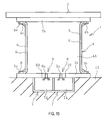
- the casing 7 can be divided into multiple casings as illustrated in FIG. 15 .
- the inner spaces 7A of the divided casings 7 can be set all to the same volume or to different volumes.
- the volume of the inner space 7A of a casing 7 having a safety valve 8 that opens at a low predetermined pressure P1 is less than the volume of the inner space 7A of a casing 7 having a safety valve 8 that opens at a high predetermined pressure P1 according to the energy absorption performance required for the fender 1.
- the volume of the inner space 7A of a casing 7 having a safety valve 8 that opens at a low predetermined pressure P1 is greater than the inner space 7A of a casing 7 having a safety valve 8 that opens at a high predetermined pressure P1. In this way, the pressure in the respective inner spaces 7A of the casings 7 can be controlled independently of the pressure in the other inner spaces 7A of the casings 7.
- the safety valve 8 can also have a variable-pressure structure allowing the predetermined pressure P1 at which the valve opens to be altered.
- the pressure at which the safety valve 8 opens can easily be altered by replacing the biasing member 9c with another having a different biasing force.
- Adopting a variable-pressure structure of this sort allows for various fenders 1 of different energy absorption performance to be easily manufactured simply by changing the safety valve 8. This minimizes the cost of manufacturing fenders 1 capable of handling ships of various sizes at an early stage, and is advantageous for manufacturing.
Landscapes
- Engineering & Computer Science (AREA)
- General Engineering & Computer Science (AREA)
- Ocean & Marine Engineering (AREA)
- Environmental & Geological Engineering (AREA)
- Mechanical Engineering (AREA)
- Civil Engineering (AREA)
- Structural Engineering (AREA)
- Safety Valves (AREA)
Abstract
Description
- The present invention relates to a pneumatic fender, and, more specifically, to a pneumatic fender that suppresses damage to a flexible hollow body and an energy-absorbing body and exhibits improved ship sway reduction effects.
- One type of pneumatic fender is a pneumatic fender comprising a flexible hollow body provided between two mounting plates. The flexible hollow body is formed from rubber in which a reinforcing layer is embedded, and is connected to the mounting plates in an airtight manner. A rear surface side of one mounting plate is mounted to a quay or the like, and a front side of the other of the mounting plates contacts a ship via a shock-receiving plate. The flexible hollow body is compressed when the ship contacts the shock-receiving plate, causing the energy from the ship to be absorbed. When an excessive amount of energy is imparted by the ship, such as when the ship forcefully collides with the shock-receiving plate, the flexible hollow body may be excessively compressed, causing damage thereto.
- A pneumatic fender in which a honeycomb-structured energy-absorbing body is provided within a flexible hollow body has been proposed (see Patent Document 1). In accordance with this pneumatic fender, the mounting plate on the front side contacts the energy-absorbing body and absorbs the energy from the ship before the flexible hollow body is excessively compressed, thereby allowing for a reduction in disadvantages such as damage to the flexible hollow body due to excess compression. However, because the energy-absorbing body is deformed and damaged by absorbing energy, it will cease functioning as an energy-absorbing body if the degree of damage is too great, requiring the pneumatic fender to be replaced.
- In addition, when the compressed flexible hollow body is restored to its original state, the ship, which had been in contact with the pneumatic fender, sways; thus, it is necessary to reduce the swaying of the ship as much as possible. Thus, there is a demand for a pneumatic fender that suppresses damage to a flexible hollow body and an energy-absorbing body and allows for further reduction in ship sway.
- Patent Document 1: Japanese Unexamined Patent Application Publication No.
H11-152728A - An object of the present invention is to provide a pneumatic fender that suppresses damage to a flexible hollow body and an energy-absorbing body and exhibits improved ship sway reduction effects.
- In order to achieve the object proposed above, a pneumatic fender according to the present invention is a pneumatic fender comprising a flexible hollow body provided between facing mounting plates, the fender comprising: an orifice that allows for communication between an interior space of the flexible hollow body and an interior space of a rigid casing that is provided on a surface of one of the mounting plates; and a safety valve that opens and allows for communication between the interior space of the flexible hollow body and the interior space of the casing by opening when the internal pressure of the flexible hollow body reaches a predetermined pressure.
- In accordance with the present invention, the safety valve opens when the internal pressure of the flexible hollow body reaches a predetermined pressure, allowing for communication between the interior space of the flexible hollow body and the interior space of the casing via the safety valve; thus, when the internal pressure of the flexible hollow body reaches a certain degree, air can flow into the inner space of the casing, suppressing increases in the internal pressure of the flexible hollow body. Damage to the flexible hollow body due to excessive compression can thus be suppressed.
- Air having flowed into the inner space of the casing then gradually returns to the inner space of the flexible hollow body through the orifice, which has a narrow opening area. The flexible hollow body is thus restored to its pre-compression state, allowing for repeated use over extended periods of time without causing damage to the casing functioning as an energy-absorbing body. In addition, the flexible hollow body is restored to its pre-compression state at a slow speed, reducing the counter force produced by this restoration. As a result, swaying of the ship contacting the pneumatic fender during this restoration can be further reduced.
-
- FIG. 1
- is a cross-sectional view illustrating an embodiment of a pneumatic fender according to the present invention in which a casing is provided within an inner space of a flexible hollow body.
- FIG. 2
- is a cross-sectional view illustrating the pneumatic fender depicted in
FIG. 1 in a state in which the flexible hollow body is beginning to compress. - FIG. 3
- is a cross-sectional view illustrating the pneumatic fender depicted in
FIG. 1 in a state in which a safety valve has opened. - FIG. 4
- is a magnified view of the casing depicted in
FIG. 3 . - FIG. 5
- is a graph showing the relationship between the level of compression of the flexible hollow body depicted in
FIG. 1 and counter force. - FIG. 6
- is a cross-sectional view illustrating another embodiment.
- FIG. 7
- is a cross-sectional view illustrating yet another embodiment.
- FIG. 8
- is a cross-sectional view illustrating an embodiment in which a casing is provided outside the flexible hollow body.
- FIG. 9
- is a cross-sectional view illustrating the pneumatic fender depicted in
FIG. 8 in a state in which the flexible hollow body is beginning to compress. - FIG. 10
- is a cross-sectional view illustrating the pneumatic fender depicted in
FIG. 8 in a state in which a safety valve has opened. - FIG. 11
- is a magnified view of the vicinity of the casing depicted in
FIG. 10 . - FIG. 12
- is a cross-sectional view illustrating a state in which air having flowed into the interior of the casing flows back to the interior of the flexible hollow body.
- FIG. 13
- is a graph showing the relationship between the level of compression of the flexible hollow body depicted in
FIG. 8 and counter force. - FIG. 14
- is a cross-sectional view illustrating another embodiment.
- FIG. 15
- is a cross-sectional view illustrating yet another embodiment.
- The pneumatic fender according to the present invention will now be described on the basis of the embodiments illustrated in the drawings.
- The
pneumatic fender 1 according to the present invention illustrated inFIG. 1 (hereinafter, referred to as "thefender 1") is provided with amounting plate 2a, amounting plate 2b, and a flexiblehollow body 4. The onemounting plate 2a is mounted on aquay 11 or the like, and a shock-receivingplate 3 is mounted on a front side of theother mounting plate 2b. The shock-receivingplate 3 contacts a side of a ship or the like. - The flexible
hollow body 4 is interposed between themounting plate 2a and themounting plate 2b and is joined to themounting plates hollow body 4 has a cylindrical shape provided withflanges 4a on both ends, and is constituted byrubber 5 in which a reinforcinglayer 6 has been embedded. The spacing H between the mountingplate 2a and the mountingplate 2b, i.e., the height dimension of the flexiblehollow body 4, is set on the basis of the energy absorption performance and the like required for thefender 1. - A
casing 7 having a projection height h is provided on a surface of the one mountingplate 2a positioned within the interior of the flexiblehollow body 4, and is disposed within aninner space 4A of the flexiblehollow body 4. Thecasing 7 is a rigid structure formed from a rigid material such as steel or iron. Thecasing 7 prevents damage caused by excess compression of the flexiblehollow body 4. - The
casing 7 can also be disposed projecting from a surface of the other mountingplate 2b within theinner space 4A of the flexiblehollow body 4. If thecasing 7 is mounted on the other mountingplate 2b, the weight of thecasing 7 acts upon the flexiblehollow body 4, which is cantileveringly disposed with respect to thequay 11. Thus, it is preferable to mount thecasing 7 to the one mountingplate 2a anchored to thequay 11 in order to eliminate the load applied to the flexiblehollow body 4 by the weight of thecasing 7. - The
casing 7 is provided with anorifice 10 and asafety valve 8. Theorifice 10 allows for communication between the space outside thecasing 7 within theinterior space 4A of the flexiblehollow body 4 and aninterior space 7A of thecasing 7. A small hole (having, for example, an opening area of about 0.5 mm2 to 80 mm2 or an opening diameter of about 1 mm to 10 mm) formed in a wall of thecasing 7 can be used as theorifice 10. Theorifice 10 is not limited to being a small hole; any structure that yields the same effects as a small hole can be used. There is no particular limitation upon the number oforifices 10, but it is preferable to provide a plurality thereof as they can conceivably become blocked for various reasons. - The
safety valve 8 opens when the internal pressure P of the flexible hollow body 4 (i.e., the pressure of the space within theinner space 4A and outside the casing 7) reaches a predetermined pressure P1. The space in theinner space 4A outside thecasing 7 and theinner space 7A of thecasing 7 communicate through theopen safety valve 8. - The
safety valve 8 of the present embodiment is constituted by a through-hole 9a formed in a wall of thecasing 7, avalve body 9b, a biasingmember 9c such as a spring, and a sealingmember 9d. Thevalve body 9b is biased by the biasingmember 9c toward the wall in which the through-hole 9a is formed. The sealingmember 9d, which is mounted to thevalve body 9b, is compression bonded to the wall so as to surround the periphery of the through-hole 9a, thereby closing thesafety valve 8 closes to block the through-hole 9a. Thesafety valve 8 is not limited to the structure described in the present embodiment; any structure in which thesafety valve 8 opens when the internal pressure P of the flexiblehollow body 4 reaches the predetermined pressure P1 is acceptable. - When a ship contacts the shock-receiving
plate 3 of thefender 1 in the state illustrated inFIG. 1 , in which the flexiblehollow body 4 is not compressed, the shock-receivingplate 3 is pressed down, as illustrated inFIG. 2 , and the flexiblehollow body 4 enters a compressed state. Thecasing 7 of thefender 1 is disposed within theinner space 4A of the flexiblehollow body 4; thus, the initial pre-compression volume of the flexiblehollow body 4 is that of theinner space 4A less the volume of thecasing 7. This allows the counter force R when the flexiblehollow body 4 first begins to be compressed to be greater than it would be if thecasing 7 were not disposed in theinner space 4A of the flexiblehollow body 4. Increased counter force R is advantageous in preventing damage as it impedes the flexiblehollow body 4 to be excessively compressed. - As illustrated in
FIGS. 3 and 4 , as the shock-receivingplate 3 is further pressed down, the flexiblehollow body 4 is further compressed, and, when the internal pressure P of the flexiblehollow body 4 reaches the predetermined pressure P1, thevalve body 9b upon which the predetermined pressure P1 has been placed moves against the biasing force of the biasingmember 9c in a direction away from the wall in which the through-hole 9a is formed. As a result, the sealingmember 9d moves away from the wall and thesafety valve 8 opens. The predetermined pressure P1 at which thesafety valve 8 opens is set, for example, to about 20% to 90% of the rated withstand pressure of thefender 1. Rated withstand pressure is the internal pressure of the flexiblehollow body 4 when the flexiblehollow body 4 is compressed at a maximum compression rate, to be described below. - The space in the
inner space 4A of the flexiblehollow body 4 outside thecasing 7 and theinner space 7A of thecasing 7 communicate through theopen safety valve 8. In this way, air A flows into theinner space 7A of thecasing 7, suppressing increases in the internal pressure P of the flexiblehollow body 4, when the internal pressure P of the flexiblehollow body 4 reaches a certain degree. - The air A that has flowed into the
inner space 7A of thecasing 7 is gradually expelled through theorifice 10 to theinner space 4A of the flexiblehollow body 4 outside of thecasing 7. The expulsion of the air A from theinner space 7A of thecasing 7 restores the flexiblehollow body 4 to its pre-compression state. In this way, thecasing 7 is made to function as an energy-absorbing body without being damaged, allowing for repeated use over extended periods of time. The flexiblehollow body 4 can also be used repeatedly over extended periods of time without damage. - In addition, because the
orifice 10 through which the air A is expelled from theinner space 7A of thecasing 7 is a small hole, the speed at which the flexiblehollow body 4 is restored to its pre-compression state is reduced. This reduces the counter force R produced by this restoration, allowing for further reduction in swaying of the ship in contact with the shock-receivingplate 3 during the restoration process. - The total opening area of the plurality of
orifices 10 is selected as appropriate; for example, the total opening area of thetotal orifices 10 is set to 1% to 30%, preferably 2% to 15%, of the area of the wall of thecasing 7. This causes the flexiblehollow body 4 to be gradually compressed when the ship berths at a low speed, which in turn ensures that the diameter and total area of theorifices 10 are suitably large with respect to the increase in the pressure in theinner space 4A and the pressure is equalized between theinner space 4A and theinner space 7A of thecasing 7, thus eliminating the effects of thecasing 7 and allowing the berthing energy of the ship to be absorbed at the soft counter force initially possessed by thefender 1. - If, on the other hand, the ship makes an abnormal berthing due to a typhoon or other type of strong winds, the flexible
hollow body 4 is dynamically compressed, causing the diameter and total opening area of theorifices 10 to be sufficiently small with respect to increases in the pressure in theinner space 4A and the volume of the flexiblehollow body 4 to become that of theinner space 4A less the volume of thecasing 7, allowing for increased counter force R. As a result, it is possible to obtain both soft counter force drawing upon the properties of the pneumatic fender according to the berthing speed of the ship and high counter force in response to abnormal berthings. -
FIG. 5 schematically shows the relationship between compression level X and counter force R in one cycle of the flexiblehollow body 4 being compressed and restored. InFIG. 5 , the solid lines represent thefender 1 of the present embodiment, and the single-dashed lines represent a conventional fender in which acasing 7 is not disposed within theinner space 4A of the flexiblehollow body 4. - During a state when compression is beginning in which the compression level X is at least 0 and less than X1, the volume of the compressed flexible
hollow body 4 is less than that of a conventional fender, as described above. This allows thefender 1 to yield greater counter force R compared to the conventional fender. - When the flexible
hollow body 4 is further compressed so that the compression level X reaches X1 and the internal pressure P of the flexiblehollow body 4 reaches a predetermined pressure P1 (the counter force R at which point being R1), thesafety valve 8 opens and air A flows into theinner space 7A of thecasing 7. The flexiblehollow body 4 remains at a generally constant internal pressure P1 until the compression level X reaches X2, suppressing increases in internal pressure and yielding a generally constant counter force R1 for the counter force R. - When the flexible
hollow body 4 is further compressed so that the compression level X reaches X2, and the inflowing air A causes the pressure in theinner space 7A to become equal to the internal pressure of the flexiblehollow body 4, the counter force R increases. After the flexiblehollow body 4 has been compressed to the point that counter force R2 is reached, the flexiblehollow body 4 is restored to its pre-compression state when the compression is released. The restoration occurs at a slow speed as described above, thereby reducing the counter force R. This is advantageous in reducing ship swaying compared to a conventional fender. - It is preferable to set the projection height h of the
casing 7 to 40% or less of the spacing H between the mountingplate 2a and the mountingplate 2b, and the volume of theinner space 7A of thecasing 7 to 10% to 35% of the volume of theinner space 4A of the flexiblehollow body 4. This is because thecasing 7 and the pressed mountingplate 2b tend to interfere with each other if the projection height h exceeds 40% of the spacing H. In addition, it is difficult to sufficiently increase the counter force R produced when the flexiblehollow body 4 begins to be compressed if the volume of theinner space 7A of thecasing 7 is less than 10% of the volume of theinner space 4A of the flexiblehollow body 4, and thecasing 7 and the pressed mountingplate 2b tend to interfere with each other if the volume of theinner space 7A of thecasing 7 exceeds 35% of the volume of theinner space 4A of the flexiblehollow body 4. - In order to impede interference between the
casing 7 and the pressed mountingplate 2b, the wall of thecasing 7 facing the mountingplate 2b may be in a planar shape parallel with the mountingplate 2b. Providing thesafety valve 8 on theinner space 7A side of thecasing 7 as in the present embodiment allows interference between thesafety valve 8 and the pressed mountingplate 2b to be prevented. - The
safety valve 8 may conceivable fail for some reason or another; thus, it is preferable to provide a plurality of valves, as illustrated inFIG. 6 . The plurality ofsafety valves 8 can all be set to open at the same predetermined pressure P1. Alternatively, at least one of the plurality ofsafety valves 8 can be set to open at a different predetermined pressure P1. - If all the
safety valves 8 are set to open at the same predetermined pressure P1, when the internal pressure P of the flexiblehollow body 4 reaches the predetermined pressure P1 (counter force R1) as shown inFIG. 5 , the compression level X of the flexiblehollow body 4 comparatively rapidly changes from X1 to X2 while maintaining a constant counter force R1, increasing compression speed. - On the other hand, if there is a mixture of
safety valves 8 that open at different timings, the horizontal linear section at which counter force R is constant shown inFIG. 5 is divided into multiple sections. This allows the compression speed of the flexiblehollow body 4 to be reduced over the former case. - If a plurality of
safety valves 8 is provided, thecasing 7 can be divided into multiple casings as illustrated inFIG. 7 . Theinner spaces 7A of the dividedcasings 7 can be set all to the same volume or to different volumes. - For example, the volume of the
inner space 7A of acasing 7 having asafety valve 8 that opens at a low predetermined pressure P1 is less than the volume of theinner space 7A of acasing 7 having asafety valve 8 that opens at a high predetermined pressure P1 according to the energy absorption performance required for thefender 1. Alternatively, the volume of theinner space 7A of acasing 7 having asafety valve 8 that opens at a low predetermined pressure P1 is greater than theinner space 7A of acasing 7 having asafety valve 8 that opens at a high predetermined pressure P1. In this way, the pressure in the respectiveinner spaces 7A of thecasings 7 can be controlled independently of the pressure in the otherinner spaces 7A of thecasings 7. - The
safety valve 8 can also have a variable-pressure structure allowing the predetermined pressure P1 at which the valve opens to be altered. In the present embodiment, the pressure at which thesafety valve 8 opens can easily be altered by replacing the biasingmember 9c with another having a different biasing force. Adopting a variable-pressure structure of this sort allows forvarious fenders 1 of different energy absorption performance to be easily manufactured simply by changing thesafety valve 8. This minimizes the cost ofmanufacturing fenders 1 capable of handling ships of various sizes at an early stage, and is advantageous for manufacturing. - The embodiment of a
fender 1 illustrated inFIG. 8 is provided with a mountingplate 2a, a mountingplate 2b, and a flexiblehollow body 4. The onemounting plate 2a is mounted on aquay 11 or the like, a shock-receivingplate 3 is mounted on a front side of the other mountingplate 2b, and the side of a ship or the like contacts the shock-receivingplate 3. - The flexible
hollow body 4 is interposed between the mountingplate 2a and the mountingplate 2b and is joined to the mountingplates plate 2a and the mountingplate 2b, i.e., the height dimension of the flexiblehollow body 4, is set on the basis of the energy absorption performance and the like required for thefender 1. - The flexible
hollow body 4 has a cylindrical shape provided withflanges 4a on both ends, and is constituted byrubber 5 in which a reinforcinglayer 6 has been embedded. Mountingholes 4b are formed in each of theflanges 4a at intervals along the circumferential direction. Anchoring members B such as bolts are embedded in the mountingholes 4b so that the heads thereof do not protrude out of the mountingholes 4b. Each of theflanges 4a is anchored to the mountingplates flanges 4a. - The
casing 7 is provided projecting from the rear surface side of the one mountingplate 2a. Specifically, thecasing 7 is mounted on an outside surface of the one mountingplate 2a opposite a side in the interior of the flexiblehollow body 4. In the present embodiment, thecasing 7 is disposed within a space formed in thequay 11. Thecasing 7 is a rigid structure formed from a rigid material such as steel or iron. - The mounting
plate 2a is provided with anorifice 10 and asafety valve 8. Theorifice 10 allows for communication between theinner space 4A of the flexiblehollow body 4 and theinterior space 7A of thecasing 7.
A small hole (having, for example, an opening area of about 0.5 mm2 to 80 mm2 or an opening diameter of about 1 mm to 10 mm) formed in the mountingplate 2a can be used as theorifice 10. Theorifice 10 is not limited to being a small hole; any structure that yields the same effects as a small hole can be used. There is no particular limitation upon the number oforifices 10, but it is preferable to provide a plurality thereof as they can conceivably become blocked for various reasons. - The
safety valve 8 provided in the mountingplate 2a opens when the internal pressure P of the flexiblehollow body 4 reaches the predetermined pressure P1. Theinner space 4A and theinner space 7A of thecasing 7 communicate through theopen safety valve 8. - The
safety valve 8 of the present embodiment is constituted by a through-hole 9a formed in the mountingplate 2a, avalve body 9b, a biasingmember 9c such as a spring, and a sealingmember 9d. Thevalve body 9b is biased by the biasingmember 9c toward the rear surface of the mountingplate 2a. The sealingmember 9d, which is mounted on thevalve body 9b, is compression bonded to the rear surface of the mountingplate 2a so as to surround the periphery of the through-hole 9a, thereby closing thesafety valve 8 to block the through-hole 9a. Thesafety valve 8 is not limited to the structure described in the present embodiment; any structure in which thesafety valve 8 opens when the internal pressure P of the flexiblehollow body 4 reaches the predetermined pressure P1 is acceptable. - When a ship contacts the other mounting
plate 2b of thefender 1 illustrated inFIG. 8 , in which the flexiblehollow body 4 is in an uncompressed state, with the shock-receivingplate 3 interposed therebetween, the mountingplate 2b is pressed down, and the flexiblehollow body 4 enters a compressed state, as illustrated inFIG. 9 . Because the internal pressure P of the flexiblehollow body 4 has not reached the predetermined pressure P1, thesafety valve 8 is not open. - As illustrated in
FIGS. 10 and 11 , as the mountingplate 2b is further pressed down, the flexiblehollow body 4 is further compressed, and, when the internal pressure P of the flexiblehollow body 4 reaches the predetermined pressure P1, thevalve body 9b upon which the predetermined pressure P1 has been placed moves against the biasing force of the biasingmember 9c in a direction away from the rear surface of the mountingplate 2a. As a result, the sealingmember 9d moves away from the rear surface of the mountingplate 2a, and thesafety valve 8 opens. The predetermined pressure P1 at which thesafety valve 8 opens is set, for example, to about 20% to 90% of the rated withstand pressure of thefender 1. Rated withstand pressure is the internal pressure of the flexiblehollow body 4 when the flexiblehollow body 4 is compressed at a maximum compression rate, to be described below. - The
inner space 4A of the flexiblehollow body 4 and theinner space 7A of thecasing 7 communicate through theopen safety valve 8. In this way, air A flows into theinner space 7A of thecasing 7, suppressing increases in the internal pressure P of the flexiblehollow body 4, when the internal pressure P of the flexiblehollow body 4 reaches a certain degree. - The opening of the
safety valve 8 causes the compressed volume when thefender 1 is pressed down to increase by the volume of theinner space 7A of thecasing 7, greatly increasing energy absorption performance. The flexiblehollow body 4 is thus capable of handling abrupt increases in the berthing energy from a ship without the need to increase the size of the flexiblehollow body 4. Concomitantly, it is also possible to suppress damage to the flexiblehollow body 4 caused by excessive compression. - Subsequently, when the ship pulls away from the shock-receiving
plate 3, the compression upon the mountingplate 2b is released, and the internal pressure P of the flexiblehollow body 4 falls below less than the predetermined internal pressure P1, thesafety valve 8 closes as illustrated inFIG. 12 . The air A that has flowed into theinner space 7A of thecasing 7 gradually flows through theorifice 10 back into theinner space 4A of the flexiblehollow body 4. The flowing back of the air A restores the flexiblehollow body 4 to its pre-compression state. In this way, thecasing 7 is made to function as an energy-absorbing body without being damaged, allowing for repeated use over extended periods of time. The flexiblehollow body 4 can also be used repeatedly over extended periods of time without damage. - In addition, because the
orifice 10 through which the air A is allowed to flow back from theinner space 7A of thecasing 7 is a small hole, the speed at which the flexiblehollow body 4 is restored to its pre-compression state is reduced. This reduces the counter force R produced by this restoration, allowing for further reduction in swaying of the ship in contact with the shock-receivingplate 3 during the restoration process. - The
total orifice 10 opening area is selected as appropriate; for example, the total opening area of a plurality oforifices 10 is set to 1% to 30%, preferably 2% to 15%, of the area of the mountingplate 2a within the range of the inner radius of the flexiblehollow body 4. This causes the flexiblehollow body 4 to be gradually compressed when the ship berths at a low speed, which in turn ensures that the diameter and total area of theorifices 10 are sufficiently large with respect to the increase in the pressure in theinner space 4A and the pressure is equalized between theinner space 4A and theinner space 7A of thecasing 7, thus allowing the berthing energy of the ship to be absorbed at the soft counter force R initially possessed by thefender 1. - If, on the other hand, the ship makes an abnormal berthing due to a typhoon or other type of strong winds, the flexible
hollow body 4 is dynamically compressed, causing the diameter and total opening area of theorifices 10 to be sufficiently small with respect to increases in the pressure in theinner space 4A and allowing the counter force R to be increased until thesafety valve 8 opens. As a result, it is possible to obtain both soft counter force drawing upon the properties of the pneumatic fender according to the berthing speed of the ship and high counter force in response to abnormal berthings. -
FIG. 13 schematically shows the relationship between compression level X and counter force R in one cycle of the flexiblehollow body 4 being compressed and restored. InFIG. 13 , the solid lines represent thefender 1 of the present embodiment, and the single-dashed lines represent a conventional fender in which acasing 7 is not disposed. - In an initial state of compression in which the compression level X is at least 0 and less than X1, counter force R similar to that of a conventional fender can be obtained. When the flexible
hollow body 4 is further compressed so that the compression level X reaches X1 and the internal pressure P of the flexiblehollow body 4 reaches a predetermined pressure P1 (the counter force R at which point being R1), thesafety valve 8 opens and air A flows into theinner space 7A of thecasing 7. The flexiblehollow body 4 remains at a generally constant internal pressure P1 until the compression level X reaches X2, suppressing increases in internal pressure and yielding a generally constant counter force R1 for the counter force R. - When the flexible
hollow body 4 is further compressed so that the compression level X reaches X2, and the inflowing air A causes the pressure in theinner space 7A to become equal to the internal pressure of the flexiblehollow body 4, the counter force R increases. After the flexiblehollow body 4 has been compressed to the point that counter force R2 is reached, the flexiblehollow body 4 is restored to its pre-compression state when the compression is released. The restoration occurs at a slow speed as described above, thereby reducing the counter force R. This is advantageous in reducing ship swaying compared to a conventional fender. - The
inner space 7A of thecasing 7 can be any desired volume; for example, the volume thereof is about 20% to 100% of the volume of theinner space 4A of the flexiblehollow body 4. There will be less improvement in the energy absorption performance of thefender 1 if the volume is less than 20% of the volume of theinner space 4A of the flexiblehollow body 4, and excessive space will be required for thecasing 7 if the volume exceeds 100% of the volume of theinner space 4A of the flexiblehollow body 4. - In the present embodiment, the compression volume can be increased by the volume of the
inner space 7A of thecasing 7. Thus, although the maximum compression rate of a conventional flexiblehollow body 4 is about 60% to 70%, a maximum compression rate of about 80% to 90% is possible in the present invention. The maximum compression rate is calculated using the spacing H between the mountingplate 2a and the mountingplate 2b (not including the thickness of the mountingplates fender 1 is in an uncompressed neutral state, and a spacing ha between the mountingplate 2a and the mountingplate 2b (not including the thickness of the mountingplates hollow body 4 is in a state of maximum compression according to the formula ((H-ha)/H) x 100 (%). Alternatively, the maximum compression rate can also be defined taking as H1 the spacing between the mountingplate 2a and the mountingplate 2b (not including the thickness of the mountingplates plate 2a and the mountingplate 2b (not including the thickness of the mountingplates hollow body 4 is in a state of maximum compression. In this case, the maximum compression rate as calculated according to the formula ((H1-h1)/H1) x 100 (%) is about 80% to 85%. - In the present embodiment, the anchoring members B are embedded in the mounting
holes 4b, preventing the outer peripheral surface of the outwardly swelling flexiblehollow body 4 from contacting the anchoring members B even if the flexiblehollow body 4 is greatly compressed as illustrated inFIG. 10 . As a result, disadvantage such as the outer peripheral surface of the flexiblehollow body 4 rubbing against and being damaged by the anchoring members B can be eliminated. By providing the corner supports 4c, it is possible to more reliably impede the outer peripheral surface of the outwardly swelling flexiblehollow body 4 from contacting the anchoring members B. As in the previously described embodiment, theflanges 4a can be anchored to the facing mountingplates holes 4b. - The
safety valve 8 may conceivable fail for some reason or another; thus, it is preferable to provide a plurality of valves, as illustrated inFIG. 14 . The plurality ofsafety valves 8 can all be set to open at the same predetermined pressure P1. Alternatively, at least one of the plurality ofsafety valves 8 can be set to open at a different predetermined pressure P1. - If all the
safety valves 8 are set to open at the same predetermined pressure P1, when the internal pressure P of the flexiblehollow body 4 reaches the predetermined pressure P1 (counter force R1) as shown inFIG. 13 , the compression level X of the flexiblehollow body 4 comparatively rapidly changes from X1 to X2 while maintaining a constant counter force R1, increasing compression speed. - On the other hand, if there is a mixture of
safety valves 8 that open at different timings, the horizontal linear section at which counter force R is constant shown inFIG. 13 is divided into multiple sections. This allows the compression speed of the flexiblehollow body 4 to be reduced over the former case. - If a plurality of
safety valves 8 is provided, thecasing 7 can be divided into multiple casings as illustrated inFIG. 15 . Theinner spaces 7A of the dividedcasings 7 can be set all to the same volume or to different volumes. - For example, the volume of the
inner space 7A of acasing 7 having asafety valve 8 that opens at a low predetermined pressure P1 is less than the volume of theinner space 7A of acasing 7 having asafety valve 8 that opens at a high predetermined pressure P1 according to the energy absorption performance required for thefender 1. Alternatively, the volume of theinner space 7A of acasing 7 having asafety valve 8 that opens at a low predetermined pressure P1 is greater than theinner space 7A of acasing 7 having asafety valve 8 that opens at a high predetermined pressure P1. In this way, the pressure in the respectiveinner spaces 7A of thecasings 7 can be controlled independently of the pressure in the otherinner spaces 7A of thecasings 7. - The
safety valve 8 can also have a variable-pressure structure allowing the predetermined pressure P1 at which the valve opens to be altered. In the present embodiment, the pressure at which thesafety valve 8 opens can easily be altered by replacing the biasingmember 9c with another having a different biasing force. Adopting a variable-pressure structure of this sort allows forvarious fenders 1 of different energy absorption performance to be easily manufactured simply by changing thesafety valve 8. This minimizes the cost ofmanufacturing fenders 1 capable of handling ships of various sizes at an early stage, and is advantageous for manufacturing. -
- 1 Pneumatic fender
- 2a, 2b Mounting plate
- 3 Shock-receiving plate
- 4 Flexible hollow body
- 4a Flange
- 4b Mounting hole
- 4c Corner support
- 4A inner space
- 5 Rubber
- 6 Reinforcing layer
- 7 Casing
- 7A Internal space
- 8 Safety valve
- 9a Through-hole
- 9b Valve body
- 9c Biasing member
- 9d Sealing member
- 10 Orifice
- 11 Quay
- B Anchoring member
Claims (10)
- A pneumatic fender comprising
a flexible hollow body provided between facing mounting plates, the fender comprising: an orifice that allows for communication between an interior space of the flexible hollow body and an interior space of a rigid casing that is provided on a surface of one of the mounting plates; and
a safety valve that opens and allows for communication between the interior space of the flexible hollow body and the interior space of the casing by opening when the internal pressure of the flexible hollow body reaches a predetermined pressure. - The pneumatic fender according to claim 1, wherein
the casing is provided on a surface of the one mounting plate positioned within the interior of the flexible hollow body. - The pneumatic fender according to claim 2, wherein
the height to which the casing projects is set to 40% or less of a spacing between the mounting plates, and the volume of the inner space of the casing is set to 10% to 35% of the volume of the inner space of the flexible hollow body. - The pneumatic fender according to claim 1, wherein
the casing is provided on an external surface of the one mounting plate on a side opposite a side in the interior of the flexible hollow body. - The pneumatic fender according to claim 4, wherein
the maximum compression rate of the flexible hollow body is set to 80% to 90%. - The pneumatic fender according to any of claims 1 to 5, wherein
a plurality of safety valves is provided. - The pneumatic fender according to claim 6, wherein
at least one of the plurality of safety valves opens at a different predetermined pressure. - The pneumatic fender according to claim 6, wherein
all of the plurality of safety valves open at the same predetermined pressure. - The pneumatic fender according to any of claims 1 to 8, wherein
the safety valve has a variable-pressure structure allowing the predetermined pressure at which the valve opens to be altered. - The pneumatic fender according to any of claims 1 to 9, wherein
anchoring members for anchoring each of flanges at both ends of the flexible hollow body to the facing mounting plates are embedded in the flanges.
Applications Claiming Priority (3)
| Application Number | Priority Date | Filing Date | Title |
|---|---|---|---|
| JP2012225814A JP5880384B2 (en) | 2012-10-11 | 2012-10-11 | Pneumatic fender |
| JP2013104184A JP6179186B2 (en) | 2013-05-16 | 2013-05-16 | Pneumatic fender |
| PCT/JP2013/077723 WO2014058044A1 (en) | 2012-10-11 | 2013-10-11 | Pneumatic fender |
Publications (4)
| Publication Number | Publication Date |
|---|---|
| EP2910684A1 true EP2910684A1 (en) | 2015-08-26 |
| EP2910684A4 EP2910684A4 (en) | 2016-08-17 |
| EP2910684B1 EP2910684B1 (en) | 2019-01-16 |
| EP2910684B9 EP2910684B9 (en) | 2019-05-15 |
Family
ID=50477506
Family Applications (1)
| Application Number | Title | Priority Date | Filing Date |
|---|---|---|---|
| EP13844770.1A Not-in-force EP2910684B9 (en) | 2012-10-11 | 2013-10-11 | Pneumatic fender |
Country Status (5)
| Country | Link |
|---|---|
| US (1) | US9428875B2 (en) |
| EP (1) | EP2910684B9 (en) |
| KR (1) | KR20150053820A (en) |
| CN (1) | CN104641044B (en) |
| WO (1) | WO2014058044A1 (en) |
Families Citing this family (2)
| Publication number | Priority date | Publication date | Assignee | Title |
|---|---|---|---|---|
| US9816241B2 (en) * | 2014-03-31 | 2017-11-14 | The Yokohama Rubber Co., Ltd. | Pneumatic fender and mouth piece metal for pneumatic fender |
| CN118372943B (en) * | 2024-06-27 | 2024-08-16 | 山东航宇船业集团股份有限公司 | Anti-collision component for ship and use method thereof |
Family Cites Families (13)
| Publication number | Priority date | Publication date | Assignee | Title |
|---|---|---|---|---|
| US3854706A (en) * | 1973-03-16 | 1974-12-17 | Stanray Corp | Shock absorbing apparatus for heavy loads |
| US4176858A (en) * | 1974-01-04 | 1979-12-04 | Safety Consultants | Energy absorbing bumper system |
| JPS5770750A (en) * | 1980-10-15 | 1982-05-01 | Michio Yoshikawa | Collision impact absorber and mpact absorbing method therefor |
| JPS6033915A (en) * | 1983-08-05 | 1985-02-21 | Yokohama Rubber Co Ltd:The | Pneumatic type fender |
| JPS60223513A (en) * | 1984-04-18 | 1985-11-08 | Yokohama Rubber Co Ltd:The | Pneumatic fender device |
| CN2036158U (en) * | 1988-07-09 | 1989-04-19 | 沈阳胶管厂 | Inflating cap type rubber fender for ship |
| JPH0438314A (en) | 1990-05-31 | 1992-02-07 | Taisei Corp | Fender device |
| JPH04208660A (en) * | 1990-08-20 | 1992-07-30 | Tsutomu Masujima | Impact cushioning bumper for vehicle |
| JPH0626022A (en) * | 1992-07-06 | 1994-02-01 | Bridgestone Corp | Gas enclosing type fender |
| JPH101928A (en) | 1996-06-17 | 1998-01-06 | Masaki Yamamoto | Low reaction type pneumatic fender |
| JP3969813B2 (en) | 1997-11-25 | 2007-09-05 | 横浜ゴム株式会社 | Pneumatic fender |
| JP4121636B2 (en) * | 1998-06-11 | 2008-07-23 | 横浜ゴム株式会社 | Pneumatic fender |
| JP5097591B2 (en) | 2008-03-27 | 2012-12-12 | 大成建設株式会社 | How to reinforce existing fenders |
-
2013
- 2013-10-11 KR KR1020157010930A patent/KR20150053820A/en not_active Ceased
- 2013-10-11 EP EP13844770.1A patent/EP2910684B9/en not_active Not-in-force
- 2013-10-11 WO PCT/JP2013/077723 patent/WO2014058044A1/en not_active Ceased
- 2013-10-11 US US14/435,147 patent/US9428875B2/en not_active Expired - Fee Related
- 2013-10-11 CN CN201380048472.8A patent/CN104641044B/en not_active Expired - Fee Related
Also Published As
| Publication number | Publication date |
|---|---|
| EP2910684B9 (en) | 2019-05-15 |
| EP2910684B1 (en) | 2019-01-16 |
| WO2014058044A1 (en) | 2014-04-17 |
| US20150345092A1 (en) | 2015-12-03 |
| CN104641044B (en) | 2016-06-08 |
| KR20150053820A (en) | 2015-05-18 |
| CN104641044A (en) | 2015-05-20 |
| EP2910684A4 (en) | 2016-08-17 |
| US9428875B2 (en) | 2016-08-30 |
Similar Documents
| Publication | Publication Date | Title |
|---|---|---|
| CN108999884B (en) | Variable-rigidity spherical hinge and variable-rigidity design method thereof | |
| US8210507B2 (en) | Hydraulically prestressed elastomer spring element and the use thereof in wind turbine bearings | |
| EP2251562A1 (en) | Air spring device | |
| CN106090103B (en) | A kind of miniature Accumulator for damper | |
| GB2087511A (en) | Self-leveling fluid damped elastomeric spring unit | |
| EP2910684B9 (en) | Pneumatic fender | |
| JP2009235782A (en) | Fender and reinforcing method of fender | |
| JP5069974B2 (en) | Vehicle suspension system | |
| CN212225854U (en) | Annular damping groove piston air spring | |
| US9845795B2 (en) | Dampening apparatus | |
| CN106523569B (en) | Oil gas shock mitigation system | |
| KR100640030B1 (en) | Fender | |
| US12037210B2 (en) | Dock bumper having progressive spring rate | |
| JP2025500679A (en) | Stopper Device | |
| CN211820170U (en) | A hydraulic cylinder with buffer function | |
| CN222169726U (en) | High-strength photovoltaic module frame corner connector | |
| JP5214299B2 (en) | Sloshing inhibitor | |
| JP6179186B2 (en) | Pneumatic fender | |
| CN206554021U (en) | A kind of rubber dam body anchor | |
| CN212297386U (en) | Shock absorber and vehicle | |
| CN205841605U (en) | The vehicle guided for the equipment and rail that weaken pressure | |
| CN109854669A (en) | A kind of combination damper and its installation method | |
| KR101874648B1 (en) | Accumulator of High Reduction Top Bracing Apparatus for Ship Engine | |
| CN208981148U (en) | A kind of Novel bracing cable explosion-proof surge guard structure | |
| KR100430645B1 (en) | Two Step Shock Absorber for Unseating Prevention |
Legal Events
| Date | Code | Title | Description |
|---|---|---|---|
| PUAI | Public reference made under article 153(3) epc to a published international application that has entered the european phase |
Free format text: ORIGINAL CODE: 0009012 |
|
| 17P | Request for examination filed |
Effective date: 20150511 |
|
| AK | Designated contracting states |
Kind code of ref document: A1 Designated state(s): AL AT BE BG CH CY CZ DE DK EE ES FI FR GB GR HR HU IE IS IT LI LT LU LV MC MK MT NL NO PL PT RO RS SE SI SK SM TR |
|
| AX | Request for extension of the european patent |
Extension state: BA ME |
|
| DAX | Request for extension of the european patent (deleted) | ||
| RA4 | Supplementary search report drawn up and despatched (corrected) |
Effective date: 20160714 |
|
| RIC1 | Information provided on ipc code assigned before grant |
Ipc: E02B 3/26 20060101AFI20160708BHEP |
|
| STAA | Information on the status of an ep patent application or granted ep patent |
Free format text: STATUS: EXAMINATION IS IN PROGRESS |
|
| 17Q | First examination report despatched |
Effective date: 20170518 |
|
| GRAP | Despatch of communication of intention to grant a patent |
Free format text: ORIGINAL CODE: EPIDOSNIGR1 |
|
| STAA | Information on the status of an ep patent application or granted ep patent |
Free format text: STATUS: GRANT OF PATENT IS INTENDED |
|
| INTG | Intention to grant announced |
Effective date: 20180726 |
|
| GRAS | Grant fee paid |
Free format text: ORIGINAL CODE: EPIDOSNIGR3 |
|
| GRAA | (expected) grant |
Free format text: ORIGINAL CODE: 0009210 |
|
| STAA | Information on the status of an ep patent application or granted ep patent |
Free format text: STATUS: THE PATENT HAS BEEN GRANTED |
|
| AK | Designated contracting states |
Kind code of ref document: B1 Designated state(s): AL AT BE BG CH CY CZ DE DK EE ES FI FR GB GR HR HU IE IS IT LI LT LU LV MC MK MT NL NO PL PT RO RS SE SI SK SM TR |
|
| REG | Reference to a national code |
Ref country code: GB Ref legal event code: FG4D |
|
| REG | Reference to a national code |
Ref country code: CH Ref legal event code: EP |
|
| REG | Reference to a national code |
Ref country code: IE Ref legal event code: FG4D |
|
| REG | Reference to a national code |
Ref country code: DE Ref legal event code: R096 Ref document number: 602013050029 Country of ref document: DE |
|
| REG | Reference to a national code |
Ref country code: AT Ref legal event code: REF Ref document number: 1089786 Country of ref document: AT Kind code of ref document: T Effective date: 20190215 |
|
| GRAT | Correction requested after decision to grant or after decision to maintain patent in amended form |
Free format text: ORIGINAL CODE: EPIDOSNCDEC |
|
| REG | Reference to a national code |
Ref country code: CH Ref legal event code: PK Free format text: BERICHTIGUNG B9 |
|
| REG | Reference to a national code |
Ref country code: NL Ref legal event code: FP |
|
| REG | Reference to a national code |
Ref country code: LT Ref legal event code: MG4D |
|
| REG | Reference to a national code |
Ref country code: NO Ref legal event code: T2 Effective date: 20190116 |
|
| REG | Reference to a national code |
Ref country code: AT Ref legal event code: MK05 Ref document number: 1089786 Country of ref document: AT Kind code of ref document: T Effective date: 20190116 |
|
| PG25 | Lapsed in a contracting state [announced via postgrant information from national office to epo] |
Ref country code: FI Free format text: LAPSE BECAUSE OF FAILURE TO SUBMIT A TRANSLATION OF THE DESCRIPTION OR TO PAY THE FEE WITHIN THE PRESCRIBED TIME-LIMIT Effective date: 20190116 Ref country code: PT Free format text: LAPSE BECAUSE OF FAILURE TO SUBMIT A TRANSLATION OF THE DESCRIPTION OR TO PAY THE FEE WITHIN THE PRESCRIBED TIME-LIMIT Effective date: 20190516 Ref country code: SE Free format text: LAPSE BECAUSE OF FAILURE TO SUBMIT A TRANSLATION OF THE DESCRIPTION OR TO PAY THE FEE WITHIN THE PRESCRIBED TIME-LIMIT Effective date: 20190116 Ref country code: PL Free format text: LAPSE BECAUSE OF FAILURE TO SUBMIT A TRANSLATION OF THE DESCRIPTION OR TO PAY THE FEE WITHIN THE PRESCRIBED TIME-LIMIT Effective date: 20190116 Ref country code: LT Free format text: LAPSE BECAUSE OF FAILURE TO SUBMIT A TRANSLATION OF THE DESCRIPTION OR TO PAY THE FEE WITHIN THE PRESCRIBED TIME-LIMIT Effective date: 20190116 Ref country code: ES Free format text: LAPSE BECAUSE OF FAILURE TO SUBMIT A TRANSLATION OF THE DESCRIPTION OR TO PAY THE FEE WITHIN THE PRESCRIBED TIME-LIMIT Effective date: 20190116 |
|
| PG25 | Lapsed in a contracting state [announced via postgrant information from national office to epo] |
Ref country code: LV Free format text: LAPSE BECAUSE OF FAILURE TO SUBMIT A TRANSLATION OF THE DESCRIPTION OR TO PAY THE FEE WITHIN THE PRESCRIBED TIME-LIMIT Effective date: 20190116 Ref country code: HR Free format text: LAPSE BECAUSE OF FAILURE TO SUBMIT A TRANSLATION OF THE DESCRIPTION OR TO PAY THE FEE WITHIN THE PRESCRIBED TIME-LIMIT Effective date: 20190116 Ref country code: BG Free format text: LAPSE BECAUSE OF FAILURE TO SUBMIT A TRANSLATION OF THE DESCRIPTION OR TO PAY THE FEE WITHIN THE PRESCRIBED TIME-LIMIT Effective date: 20190416 Ref country code: IS Free format text: LAPSE BECAUSE OF FAILURE TO SUBMIT A TRANSLATION OF THE DESCRIPTION OR TO PAY THE FEE WITHIN THE PRESCRIBED TIME-LIMIT Effective date: 20190516 Ref country code: GR Free format text: LAPSE BECAUSE OF FAILURE TO SUBMIT A TRANSLATION OF THE DESCRIPTION OR TO PAY THE FEE WITHIN THE PRESCRIBED TIME-LIMIT Effective date: 20190417 Ref country code: RS Free format text: LAPSE BECAUSE OF FAILURE TO SUBMIT A TRANSLATION OF THE DESCRIPTION OR TO PAY THE FEE WITHIN THE PRESCRIBED TIME-LIMIT Effective date: 20190116 |
|
| REG | Reference to a national code |
Ref country code: DE Ref legal event code: R097 Ref document number: 602013050029 Country of ref document: DE |
|
| PG25 | Lapsed in a contracting state [announced via postgrant information from national office to epo] |
Ref country code: AT Free format text: LAPSE BECAUSE OF FAILURE TO SUBMIT A TRANSLATION OF THE DESCRIPTION OR TO PAY THE FEE WITHIN THE PRESCRIBED TIME-LIMIT Effective date: 20190116 Ref country code: DK Free format text: LAPSE BECAUSE OF FAILURE TO SUBMIT A TRANSLATION OF THE DESCRIPTION OR TO PAY THE FEE WITHIN THE PRESCRIBED TIME-LIMIT Effective date: 20190116 Ref country code: EE Free format text: LAPSE BECAUSE OF FAILURE TO SUBMIT A TRANSLATION OF THE DESCRIPTION OR TO PAY THE FEE WITHIN THE PRESCRIBED TIME-LIMIT Effective date: 20190116 Ref country code: CZ Free format text: LAPSE BECAUSE OF FAILURE TO SUBMIT A TRANSLATION OF THE DESCRIPTION OR TO PAY THE FEE WITHIN THE PRESCRIBED TIME-LIMIT Effective date: 20190116 Ref country code: RO Free format text: LAPSE BECAUSE OF FAILURE TO SUBMIT A TRANSLATION OF THE DESCRIPTION OR TO PAY THE FEE WITHIN THE PRESCRIBED TIME-LIMIT Effective date: 20190116 Ref country code: IT Free format text: LAPSE BECAUSE OF FAILURE TO SUBMIT A TRANSLATION OF THE DESCRIPTION OR TO PAY THE FEE WITHIN THE PRESCRIBED TIME-LIMIT Effective date: 20190116 Ref country code: AL Free format text: LAPSE BECAUSE OF FAILURE TO SUBMIT A TRANSLATION OF THE DESCRIPTION OR TO PAY THE FEE WITHIN THE PRESCRIBED TIME-LIMIT Effective date: 20190116 Ref country code: SK Free format text: LAPSE BECAUSE OF FAILURE TO SUBMIT A TRANSLATION OF THE DESCRIPTION OR TO PAY THE FEE WITHIN THE PRESCRIBED TIME-LIMIT Effective date: 20190116 |
|
| PLBE | No opposition filed within time limit |
Free format text: ORIGINAL CODE: 0009261 |
|
| STAA | Information on the status of an ep patent application or granted ep patent |
Free format text: STATUS: NO OPPOSITION FILED WITHIN TIME LIMIT |
|
| PG25 | Lapsed in a contracting state [announced via postgrant information from national office to epo] |
Ref country code: SM Free format text: LAPSE BECAUSE OF FAILURE TO SUBMIT A TRANSLATION OF THE DESCRIPTION OR TO PAY THE FEE WITHIN THE PRESCRIBED TIME-LIMIT Effective date: 20190116 |
|
| 26N | No opposition filed |
Effective date: 20191017 |
|
| PG25 | Lapsed in a contracting state [announced via postgrant information from national office to epo] |
Ref country code: SI Free format text: LAPSE BECAUSE OF FAILURE TO SUBMIT A TRANSLATION OF THE DESCRIPTION OR TO PAY THE FEE WITHIN THE PRESCRIBED TIME-LIMIT Effective date: 20190116 |
|
| PG25 | Lapsed in a contracting state [announced via postgrant information from national office to epo] |
Ref country code: TR Free format text: LAPSE BECAUSE OF FAILURE TO SUBMIT A TRANSLATION OF THE DESCRIPTION OR TO PAY THE FEE WITHIN THE PRESCRIBED TIME-LIMIT Effective date: 20190116 |
|
| REG | Reference to a national code |
Ref country code: DE Ref legal event code: R119 Ref document number: 602013050029 Country of ref document: DE |
|
| REG | Reference to a national code |
Ref country code: NO Ref legal event code: MMEP |
|
| PG25 | Lapsed in a contracting state [announced via postgrant information from national office to epo] |
Ref country code: MC Free format text: LAPSE BECAUSE OF FAILURE TO SUBMIT A TRANSLATION OF THE DESCRIPTION OR TO PAY THE FEE WITHIN THE PRESCRIBED TIME-LIMIT Effective date: 20190116 |
|
| REG | Reference to a national code |
Ref country code: CH Ref legal event code: PL |
|
| REG | Reference to a national code |
Ref country code: NL Ref legal event code: MM Effective date: 20191101 |
|
| PG25 | Lapsed in a contracting state [announced via postgrant information from national office to epo] |
Ref country code: DE Free format text: LAPSE BECAUSE OF NON-PAYMENT OF DUE FEES Effective date: 20200501 Ref country code: NO Free format text: LAPSE BECAUSE OF NON-PAYMENT OF DUE FEES Effective date: 20191031 Ref country code: LU Free format text: LAPSE BECAUSE OF NON-PAYMENT OF DUE FEES Effective date: 20191011 Ref country code: LI Free format text: LAPSE BECAUSE OF NON-PAYMENT OF DUE FEES Effective date: 20191031 Ref country code: CH Free format text: LAPSE BECAUSE OF NON-PAYMENT OF DUE FEES Effective date: 20191031 |
|
| REG | Reference to a national code |
Ref country code: BE Ref legal event code: MM Effective date: 20191031 |
|
| PG25 | Lapsed in a contracting state [announced via postgrant information from national office to epo] |
Ref country code: BE Free format text: LAPSE BECAUSE OF NON-PAYMENT OF DUE FEES Effective date: 20191031 Ref country code: NL Free format text: LAPSE BECAUSE OF NON-PAYMENT OF DUE FEES Effective date: 20191101 |
|
| GBPC | Gb: european patent ceased through non-payment of renewal fee |
Effective date: 20191011 |
|
| PG25 | Lapsed in a contracting state [announced via postgrant information from national office to epo] |
Ref country code: GB Free format text: LAPSE BECAUSE OF NON-PAYMENT OF DUE FEES Effective date: 20191011 Ref country code: IE Free format text: LAPSE BECAUSE OF NON-PAYMENT OF DUE FEES Effective date: 20191011 Ref country code: FR Free format text: LAPSE BECAUSE OF NON-PAYMENT OF DUE FEES Effective date: 20191031 |
|
| PG25 | Lapsed in a contracting state [announced via postgrant information from national office to epo] |
Ref country code: CY Free format text: LAPSE BECAUSE OF FAILURE TO SUBMIT A TRANSLATION OF THE DESCRIPTION OR TO PAY THE FEE WITHIN THE PRESCRIBED TIME-LIMIT Effective date: 20190116 |
|
| PG25 | Lapsed in a contracting state [announced via postgrant information from national office to epo] |
Ref country code: HU Free format text: LAPSE BECAUSE OF FAILURE TO SUBMIT A TRANSLATION OF THE DESCRIPTION OR TO PAY THE FEE WITHIN THE PRESCRIBED TIME-LIMIT; INVALID AB INITIO Effective date: 20131011 Ref country code: MT Free format text: LAPSE BECAUSE OF FAILURE TO SUBMIT A TRANSLATION OF THE DESCRIPTION OR TO PAY THE FEE WITHIN THE PRESCRIBED TIME-LIMIT Effective date: 20190116 |
|
| PG25 | Lapsed in a contracting state [announced via postgrant information from national office to epo] |
Ref country code: MK Free format text: LAPSE BECAUSE OF FAILURE TO SUBMIT A TRANSLATION OF THE DESCRIPTION OR TO PAY THE FEE WITHIN THE PRESCRIBED TIME-LIMIT Effective date: 20190116 |