EP2910430A1 - System for performing electrical tests to electrical wiring harnesses - Google Patents
System for performing electrical tests to electrical wiring harnesses Download PDFInfo
- Publication number
- EP2910430A1 EP2910430A1 EP14382061.1A EP14382061A EP2910430A1 EP 2910430 A1 EP2910430 A1 EP 2910430A1 EP 14382061 A EP14382061 A EP 14382061A EP 2910430 A1 EP2910430 A1 EP 2910430A1
- Authority
- EP
- European Patent Office
- Prior art keywords
- test terminals
- connectors
- adapter modules
- test
- wiring harness
- Prior art date
- Legal status (The legal status is an assumption and is not a legal conclusion. Google has not performed a legal analysis and makes no representation as to the accuracy of the status listed.)
- Granted
Links
Images

Classifications
-
- G—PHYSICS
- G01—MEASURING; TESTING
- G01R—MEASURING ELECTRIC VARIABLES; MEASURING MAGNETIC VARIABLES
- G01R31/00—Arrangements for testing electric properties; Arrangements for locating electric faults; Arrangements for electrical testing characterised by what is being tested not provided for elsewhere
- G01R31/50—Testing of electric apparatus, lines, cables or components for short-circuits, continuity, leakage current or incorrect line connections
- G01R31/58—Testing of lines, cables or conductors
-
- B—PERFORMING OPERATIONS; TRANSPORTING
- B60—VEHICLES IN GENERAL
- B60R—VEHICLES, VEHICLE FITTINGS, OR VEHICLE PARTS, NOT OTHERWISE PROVIDED FOR
- B60R16/00—Electric or fluid circuits specially adapted for vehicles and not otherwise provided for; Arrangement of elements of electric or fluid circuits specially adapted for vehicles and not otherwise provided for
- B60R16/02—Electric or fluid circuits specially adapted for vehicles and not otherwise provided for; Arrangement of elements of electric or fluid circuits specially adapted for vehicles and not otherwise provided for electric constitutive elements
- B60R16/0207—Wire harnesses
-
- G—PHYSICS
- G01—MEASURING; TESTING
- G01R—MEASURING ELECTRIC VARIABLES; MEASURING MAGNETIC VARIABLES
- G01R31/00—Arrangements for testing electric properties; Arrangements for locating electric faults; Arrangements for electrical testing characterised by what is being tested not provided for elsewhere
- G01R31/50—Testing of electric apparatus, lines, cables or components for short-circuits, continuity, leakage current or incorrect line connections
- G01R31/66—Testing of connections, e.g. of plugs or non-disconnectable joints
- G01R31/68—Testing of releasable connections, e.g. of terminals mounted on a printed circuit board
- G01R31/69—Testing of releasable connections, e.g. of terminals mounted on a printed circuit board of terminals at the end of a cable or a wire harness; of plugs; of sockets, e.g. wall sockets or power sockets in appliances
-
- H—ELECTRICITY
- H01—ELECTRIC ELEMENTS
- H01R—ELECTRICALLY-CONDUCTIVE CONNECTIONS; STRUCTURAL ASSOCIATIONS OF A PLURALITY OF MUTUALLY-INSULATED ELECTRICAL CONNECTING ELEMENTS; COUPLING DEVICES; CURRENT COLLECTORS
- H01R43/00—Apparatus or processes specially adapted for manufacturing, assembling, maintaining, or repairing of line connectors or current collectors or for joining electric conductors
- H01R43/28—Apparatus or processes specially adapted for manufacturing, assembling, maintaining, or repairing of line connectors or current collectors or for joining electric conductors for wire processing before connecting to contact members, not provided for in groups H01R43/02 - H01R43/26
Definitions
- the present invention relates to a system for performing electrical tests to electrical wiring harnesses of any size, number of components and spatial distribution, such as those designed for the aeronautical industry, the naval industry or the automotive industry.
- An electrical wiring harness is formed by a bundle of wires of different types arranged in a particular order which are bound together in order to facilitate the installation, repair and maintenance of the wires and the connection of a plurality of equipment distant from each other.
- the electrical wiring harnesses used in particular in the aeronautic industry are quite complex by the number of wires and connectors that they have. They are manufactured in workbenches such as those described in US 6,272,387 , US 6,625,299 , US 7,507,113 and EP 2 575 147 A2 that include computer systems that provide information to assist the workers involved in the manufacturing process.
- One of the problems raised by said tests is the connection of the connectors of the electrical wiring harnesses to the test machines because the general purpose of the wire testing machines, on the one hand, and the specific typology of the connectors of the wiring harnesses of each particular industry, on the other hand, shall be combined.
- the object of the present invention is to provide a system to perform electrical tests quickly and accurately to any electrical wiring harness regardless of the position, number and type of components that conform it.
- a system comprising a workstation equipped with an electrical test machine provided with test terminals disposed on the end of extendable hoses, a connection interface between harness connectors and terminals tests, a working board to perform on it the electrical tests to a harness, one or more projection devices arranged to project images onto the working board and a computer system to supply such projection devices with images to assist the operators performing the tests.
- Said connection interface is formed by adapter modules connectable by one face to the wiring harness connectors and by other face to the test terminals. Test terminals and adapter modules comprise electronic circuits and external identification labels holding identification information of them.
- This system simplifies and facilitates the preparation and execution of the test of any electrical wiring harness regardless of its size, number and distribution of components.
- the ability to approach the test points of the machine to the space point where the harness component is located, as well as the possibility of increasing the number and type of adapter modules, depending on the existing needs, allows configuring the system for performing the test of any typology of electrical wiring harness.
- the system assists the end-user in the preparation and execution operations of the electrical test, guiding step by step the connection of the wiring harness to the test machine, indicating visually to the operator the position of the harness connector and the mobile test terminal and showing additionally the identification code of the adapter module associated with each component of the harness in each preparation task and allow checking the correct connection of the equipment processing the identification codes housed in said electronic circuits,
- the system also includes cameras to take images of the operations in the working board that can allow the identification of, in particular, the adapter modules placed on the working board processing the identifier codes contained in their external labels.
- the test terminals comprise connectors with a predetermined number of connection points and the connection interface between harness connectors and test terminals comprise different adapter modules for each type of harness connector having the corresponding counter-connector disposed on one face and. on the opposite face, a connector with the same number and configuration of connection points than the connectors of the test terminals.
- the main components of the system for testing electrical wiring harnesses according to the invention are:
- Test terminals 19 and adapter modules 41 include cards with electronic circuits that are connected via a bus to a communication card installed in the computer of the computer system 31, which may be located next to the electrical testing machine 12.
- the software of the computer system 31 is also adapted to record in memory units of said electronic circuits identification codes of test terminals 19 and adapter modules 41.
- the software can also be adapted to identify the adapter modules 41 located on the working board 10 by processing their external identification codes, which can be, for example, bi-dimensional barcodes included in their identification labels taken from images captured by said cameras 25, 25'.
- Figure 2b shows schematically an example of an image 40 that would be projected by the projecting devices 21, 21', 21" on the working board 10 and which would overlap the electrical wiring harness 11 shown in Figure 2a .
- image 40 the adapter modules 41 and test terminals 19 arranged at the end of extensible hoses 17 that shall be used for each connector 13 of the electrical wiring harness 11 are shown.
- the representations of all elements included in image 40 would include their identification although, for simplicity, are not shown in Figure 2b . With this information, the operator can perform the connection operation of the electrical wiring harness 11 to the electrical testing machine 12 quickly and accurately.
- the generation of images such as image 40 may be done adapting known software.
- the computer system 31 may also provide sequentially images with, only, the relevant information for each step of the connecting process of the electrical wiring harness 11 to the electrical testing machine 12.
- the computer system 31 can also provide images identifying elements in which a connecting error has been detected during a test performed with said purpose. For its generation the computer system 31 not only processes information contained in the documentation repository 33 but also information received from the electrical testing machine 12 by means of the identification system formed by the electronic circuitry incorporated in the test terminals 19 and the adapter modules 41.
- connection faces between the adapter modules 41 and the test terminals 19 are configured to facilitate coupling.
- the main features of this configuration are the following:
- test terminals 19 have in the rear face a strain relief device 69 of extensible hoses 17 entering into them formed by two pieces that are screwed one on top of the other as a clamp.
- the test terminals 19 may be configured with a lighting device therein, such as, for example, a LED arranged so that its light can propagate through a slot 62 suitably shaped as a waveguide (see Figure 3b ).
- a lighting device such as, for example, a LED arranged so that its light can propagate through a slot 62 suitably shaped as a waveguide (see Figure 3b ).
Landscapes
- Physics & Mathematics (AREA)
- General Physics & Mathematics (AREA)
- Testing Of Short-Circuits, Discontinuities, Leakage, Or Incorrect Line Connections (AREA)
Abstract
Description
- The present invention relates to a system for performing electrical tests to electrical wiring harnesses of any size, number of components and spatial distribution, such as those designed for the aeronautical industry, the naval industry or the automotive industry.
- An electrical wiring harness is formed by a bundle of wires of different types arranged in a particular order which are bound together in order to facilitate the installation, repair and maintenance of the wires and the connection of a plurality of equipment distant from each other.
- The electrical wiring harnesses used in particular in the aeronautic industry are quite complex by the number of wires and connectors that they have. They are manufactured in workbenches such as those described in
US 6,272,387 ,US 6,625,299 ,US 7,507,113 andEP 2 575 147 A2 that include computer systems that provide information to assist the workers involved in the manufacturing process. - After being manufactured an electrical wiring harness must be subject to continuity and insulation electrical tests to ensure it meets the electrical specifications required and that has been correctly assembled.
- One of the problems raised by said tests is the connection of the connectors of the electrical wiring harnesses to the test machines because the general purpose of the wire testing machines, on the one hand, and the specific typology of the connectors of the wiring harnesses of each particular industry, on the other hand, shall be combined.
- To solve this problem, interfaces for connecting wiring harnesses to electrical test machines such as those described in
US 5,072,185 andUS 7,112,969 have been proposed. However, for complex electrical wiring harnesses as those used in the aircraft industry, the connection operation to the test machine is laborious and prone to making mistakes even using interface elements such as the abovementioned. - The object of the present invention is to provide a system to perform electrical tests quickly and accurately to any electrical wiring harness regardless of the position, number and type of components that conform it.
- This object is achieved by a system comprising a workstation equipped with an electrical test machine provided with test terminals disposed on the end of extendable hoses, a connection interface between harness connectors and terminals tests, a working board to perform on it the electrical tests to a harness, one or more projection devices arranged to project images onto the working board and a computer system to supply such projection devices with images to assist the operators performing the tests. Said connection interface is formed by adapter modules connectable by one face to the wiring harness connectors and by other face to the test terminals. Test terminals and adapter modules comprise electronic circuits and external identification labels holding identification information of them.
- This system simplifies and facilitates the preparation and execution of the test of any electrical wiring harness regardless of its size, number and distribution of components. The ability to approach the test points of the machine to the space point where the harness component is located, as well as the possibility of increasing the number and type of adapter modules, depending on the existing needs, allows configuring the system for performing the test of any typology of electrical wiring harness.
- Moreover, the system assists the end-user in the preparation and execution operations of the electrical test, guiding step by step the connection of the wiring harness to the test machine, indicating visually to the operator the position of the harness connector and the mobile test terminal and showing additionally the identification code of the adapter module associated with each component of the harness in each preparation task and allow checking the correct connection of the equipment processing the identification codes housed in said electronic circuits,
- Advantageously, the system also includes cameras to take images of the operations in the working board that can allow the identification of, in particular, the adapter modules placed on the working board processing the identifier codes contained in their external labels.
- In one embodiment of the invention, the test terminals comprise connectors with a predetermined number of connection points and the connection interface between harness connectors and test terminals comprise different adapter modules for each type of harness connector having the corresponding counter-connector disposed on one face and. on the opposite face, a connector with the same number and configuration of connection points than the connectors of the test terminals. This structuring of the test terminals and adapter modules contributes positively to simplify the tasks of preparation and execution of tests.
- Other desirable features and advantages of this invention will become apparent from the subsequent detailed description of the invention and the appended claims, in relation with the enclosed drawings.
-
-
Figure 1 is a schematic representation of an electrical wiring harness disposed on a working board to perform electrical tests illustrating some of the components of the system of the invention. -
Figure 2a is a schematic plan view of a wiring harness disposed on a working board andFigure 2b is a schematic image illustrating the support information projected on said board, overlapped over the wiring harness, to facilitate the realization of the operations necessary to perform said electrical tests. -
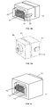
Figures 3a and 3b are perspective views of a test terminal of the test machine showing, respectively, its front and rear faces. -
Figure 4 is a perspective view of an adapter module that is used as an interface between the connectors of the electrical wiring harnesses and the test terminals. -
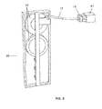
Figure 5 is a perspective view of an extension-collecting device of a hose having mounted in its end a test terminal with an adapter module coupled thereto. - The main components of the system for testing electrical wiring harnesses according to the invention are:
- A
workstation 15 including anelectrical testing machine 12 with a plurality ofmobile test terminals 19 for approaching the machine points to the use points and a workingboard 10. Thetest terminals 19 are attached toextendable hoses 17 actuated by means ofdevices 35 based onpulleys 37 integrated in theworkstation 15 to enable their movement away from it to perform the tests and their retreat once the tests have been ended. Theelectrical testing machine 12 generates electrical stimuli (voltage and current) and receives responses so that resistance values can be measured to perform continuity and insulation tests. It has stimulation and acquisition cards capable of holding thousands of possible test points. -
Adapter modules 41 as interface elements between theconnectors 13 of theelectrical wiring harnesses 11 and thetests terminals 19. For each type ofconnector 13 of an electrical wiring harness, anadapter module 41 with one face configured as itscorresponding counter-connector 77 is available. Theelectrical wiring harness 11 subject to testing is fixed on the workingboard 10. To perform the electrical tests eachconnector 13 of theelectrical wiring harness 11 must be connected to anadapter module 41 and the later to atest terminal 19 on the workingboard 10. - Several projecting
devices board 10 images that display information concerning the electrical test operations and particularly the connecting operation of theelectrical wiring harness 11 to theelectrical testing machine 12 and to the checking operation to asses that that the connection has been properly made. In the embodiment shown inFigure 1 thedevices projectors board 10 andmirrors board 10. In other embodiments where ahorizontal working board 10 is not used theprojecting devices board 10. The projectingdevices board 10. Their number depends, among other factors, the size of the workingboard 10. - Optionally
several cameras 25, 25' to capture images of the operations performed on the workingboard 10. - A
computer system 31 comprising a computer, connected to the abovementioned devices and components and to adocumentation repository 33 containing information about theelectrical wiring harness 11 and the operations to be performed during the electrical tests, and software adapted to generate images with support information on such operations so that the operator can perform them quickly and accurately. -
Test terminals 19 andadapter modules 41 include cards with electronic circuits that are connected via a bus to a communication card installed in the computer of thecomputer system 31, which may be located next to theelectrical testing machine 12. The software of thecomputer system 31 is also adapted to record in memory units of said electronic circuits identification codes oftest terminals 19 andadapter modules 41. Optionally, the software can also be adapted to identify theadapter modules 41 located on the workingboard 10 by processing their external identification codes, which can be, for example, bi-dimensional barcodes included in their identification labels taken from images captured bysaid cameras 25, 25'. -
Figure 2b shows schematically an example of animage 40 that would be projected by theprojecting devices board 10 and which would overlap theelectrical wiring harness 11 shown inFigure 2a . In theimage 40 theadapter modules 41 andtest terminals 19 arranged at the end ofextensible hoses 17 that shall be used for eachconnector 13 of theelectrical wiring harness 11 are shown. The representations of all elements included inimage 40 would include their identification although, for simplicity, are not shown inFigure 2b . With this information, the operator can perform the connection operation of theelectrical wiring harness 11 to theelectrical testing machine 12 quickly and accurately. The generation of images such asimage 40 may be done adapting known software. - The
computer system 31 may also provide sequentially images with, only, the relevant information for each step of the connecting process of theelectrical wiring harness 11 to theelectrical testing machine 12. - The
computer system 31 can also provide images identifying elements in which a connecting error has been detected during a test performed with said purpose. For its generation thecomputer system 31 not only processes information contained in thedocumentation repository 33 but also information received from theelectrical testing machine 12 by means of the identification system formed by the electronic circuitry incorporated in thetest terminals 19 and theadapter modules 41. - In the embodiment illustrated in
Figures 3a and 4 , the respective connection faces between theadapter modules 41 and thetest terminals 19 are configured to facilitate coupling. The main features of this configuration are the following: - The
connectors test terminals 19 and theadapter modules 41 have the same number of connection points, for example 70. They are, preferably, quick coupling connectors of retractable pins. - The
connectors 71 of theadapter modules 41 are arranged in arecessed space 73 so that theconnectors 61 of thetest terminals 19 can be housed in it. Their coupling is facilitated by theframes 63 of thetest terminals 19 which are arranged to fit into saidrecess space 73. - The
test terminals 19 include anelement 67 of a flange device to be locked when connected to theadapter modules 41 cooperating with aspring 75 disposed therein. Thetest terminals 19 include abutton 65 that allows unlocking the flange device. - Moreover, in the embodiment illustrated in
Figures 3b and5 , thetest terminals 19 have in the rear face astrain relief device 69 ofextensible hoses 17 entering into them formed by two pieces that are screwed one on top of the other as a clamp. - The
test terminals 19 may be configured with a lighting device therein, such as, for example, a LED arranged so that its light can propagate through aslot 62 suitably shaped as a waveguide (seeFigure 3b ). - Among the advantages of the present invention the following can be mentioned:
- Testing of electrical wiring harnesses 11 can be performed with support information provided sequentially for the various steps involved in their execution.
- Ease to connect without error the
adapter modules 41 to theconnectors 13 of the electrical wiring harnesses 11 and thetest terminals 19 to theadapter modules 41. - Radical decrease of the time required to perform the connection operations.
- Absence of errors thanks to the built-in identification system included in
test terminals 19 andadapter modules 41. - Although the present invention has been described in connection with various embodiments, it will be appreciated from the specification that various combinations of elements, variations or improvements therein may be made, and are within the scope of the invention.
Claims (7)
- System for performing electrical tests to an electrical wiring harness (11) comprising a workstation (15) with an electrical testing machine (12) provided with test terminals (19) and a connection interface between harness connectors (13) and test terminals (19), characterized in that:- the test terminals (19) are arranged at the end of expandable hoses (17) from the electrical testing machine (12) so that they can move away from it;- the connection interface is formed by adapter modules (41) connectable by one face to the wiring harness connectors (13) and by other face to the test terminals (19);- the test terminals (19) and the adapter modules (41) comprise electronic circuits with at least memory units to hold identification information of them;- the workstation (15) also comprises a working board (10) to perform on it, firstly, the connection of the adapter modules (41) to the wiring harness connectors (13) and to the test terminals (19) and, secondly, the testing of the electrical wiring harness (11) and one or more projecting devices (21, 21', 21") arranged to project images onto the working board (10);- the system also comprises a computer system (31) including a computer connected to said projecting devices (21, 21', 21"), to the mentioned components for testing an electrical wiring harness (11) and to a documentation repository (33) concerning the electrical wiring harness (11) subject of test, and a software adapted to supply to said projecting devices (21, 21', 21") images (40) concerning the test of the electrical wiring harness (11) allowing operators to perform it using only the support information provided by said images (40).
- The system of claim 1 further comprising one or more cameras (25, 25') arranged to capture images of the operations performed on the working board (10) and connected to the computer of the computer system (31) and wherein said software is adapted for processing the external identification labels of the adapter modules (41) contained in the images captured by said cameras (25, 25') to identify them.
- System according to any of claims 1-2, wherein:- the test terminals (19) comprise connectors (61) with a predetermined number of connection points;- the connection interface between harness connectors (13) and the test terminals (19) comprises different adapter modules (41) for each type of harness connector (13) with the corresponding counter-connector (77) arranged in one face and with a connector (71) with the same number and the same configuration of connection points of the connectors (61) of test terminals (19) on an opposite face.
- System according to claim 3, wherein:- the connectors (61) of the test terminals (19) are arranged protruding from his connection face with the adapter modules (41);- the connectors (71) of the adapter modules (41) are disposed in a recessed space (73) of the connecting face with the test terminals (19);- the test terminals (19) comprise a frame (63) protruding from its connection face with the adapter modules (41) arranged to fit on the inner edge of said recess space (73) of the adapter modules (41) facilitating the coupling of the connectors (61) of the test terminals (19) with the connectors (71) of the adapter modules (41);- the test terminals (19) and the adapter modules (41) comprise cooperating elements (67, 75) of a flange device that allows locking them when they are coupled and the test terminals (19) also comprise actuating means (65) of said flange device for unlocking them.
- System according to any of claims 1-4, wherein the test terminals (19) comprise at least one lighting means arranged inside a slot (62) configured as a waveguide for the light emitted by said means.
- System according to any of claims 1-5, wherein the test terminals (19) comprise on their connecting face with the extendable hoses (17) a strain relief device (69) of the extendable hoses (17).
- System according to any of claims 1-6, wherein the workstation (15) includes devices (35) with pulleys (37) to extend/retract said expandable hoses (17).
Priority Applications (5)
| Application Number | Priority Date | Filing Date | Title |
|---|---|---|---|
| ES14382061T ES2751372T3 (en) | 2014-02-24 | 2014-02-24 | System for conducting electrical tests on electrical harnesses |
| EP14382061.1A EP2910430B1 (en) | 2014-02-24 | 2014-02-24 | System for performing electrical tests to electrical wiring harnesses |
| CN201510132974.XA CN104865460B (en) | 2014-02-24 | 2015-02-17 | System for carrying out electrical testing to wirning harness |
| CA2882174A CA2882174C (en) | 2014-02-24 | 2015-02-17 | System for performing electrical tests to electrical wiring harnesses |
| US14/630,207 US9664722B2 (en) | 2014-02-24 | 2015-02-24 | System for performing electrical tests to electrical wiring harnesses |
Applications Claiming Priority (1)
| Application Number | Priority Date | Filing Date | Title |
|---|---|---|---|
| EP14382061.1A EP2910430B1 (en) | 2014-02-24 | 2014-02-24 | System for performing electrical tests to electrical wiring harnesses |
Publications (2)
| Publication Number | Publication Date |
|---|---|
| EP2910430A1 true EP2910430A1 (en) | 2015-08-26 |
| EP2910430B1 EP2910430B1 (en) | 2019-05-15 |
Family
ID=50239566
Family Applications (1)
| Application Number | Title | Priority Date | Filing Date |
|---|---|---|---|
| EP14382061.1A Active EP2910430B1 (en) | 2014-02-24 | 2014-02-24 | System for performing electrical tests to electrical wiring harnesses |
Country Status (5)
| Country | Link |
|---|---|
| US (1) | US9664722B2 (en) |
| EP (1) | EP2910430B1 (en) |
| CN (1) | CN104865460B (en) |
| CA (1) | CA2882174C (en) |
| ES (1) | ES2751372T3 (en) |
Cited By (7)
| Publication number | Priority date | Publication date | Assignee | Title |
|---|---|---|---|---|
| WO2018178847A1 (en) * | 2017-03-29 | 2018-10-04 | Divmac - Projectos, Automatismos E Periféricos Industriais, S.A | Wire harness test system and method of operation thereof |
| DE102017126491A1 (en) * | 2017-11-10 | 2019-05-16 | Engberts Mess-, Steuer- Und Regelsysteme Gmbh | Method for configuring a test table and a test system for carrying out the method |
| JP2020145783A (en) * | 2019-03-04 | 2020-09-10 | 日立金属株式会社 | Wire harness inspection device and wire harness inspection method |
| CN113281679A (en) * | 2021-05-20 | 2021-08-20 | 上海贝恩科电缆有限公司 | Wire harness continuity electrical performance test system and method supporting MES system |
| EP3872512A1 (en) * | 2020-02-27 | 2021-09-01 | Aptiv Technologies Limited | Wiring assembly board and method for verifying connections when assembling a wire harness |
| US11543464B2 (en) | 2020-02-27 | 2023-01-03 | Aptiv Technologies Limited | Wire harness test device and method for verifying connections when assembling a wire harness |
| US11954252B2 (en) | 2020-02-27 | 2024-04-09 | Aptiv Technologies AG | Component connection verification device and method |
Families Citing this family (14)
| Publication number | Priority date | Publication date | Assignee | Title |
|---|---|---|---|---|
| JP6483046B2 (en) * | 2016-04-14 | 2019-03-13 | 日立オートモティブシステムズ株式会社 | Verification system and verification method for vehicle electronic control device |
| JP2018087750A (en) * | 2016-11-29 | 2018-06-07 | 住友電装株式会社 | Method and device for inspecting wire harness |
| DE102018113989B4 (en) * | 2018-06-12 | 2020-01-16 | Lisa Dräxlmaier GmbH | MANUFACTURING DEVICE AND METHOD |
| US10996286B2 (en) * | 2018-11-29 | 2021-05-04 | The Boeing Company | Test system and method for a wiring harness |
| JP7180529B2 (en) | 2019-05-10 | 2022-11-30 | 日立金属株式会社 | Wire harness manufacturing equipment |
| CN113687268B (en) * | 2021-09-15 | 2024-10-08 | 济南友丰电子有限公司 | Automobile wiring harness detection device |
| CN115902712B (en) * | 2022-12-27 | 2025-06-10 | 无锡吉兴汽车声学部件科技有限公司 | Automobile roof harness detection device and detection method |
| CN117110760B (en) * | 2023-09-14 | 2024-10-18 | 成都飞机工业(集团)有限责任公司 | Aviation harness distributed detection method |
| US12578359B2 (en) | 2023-09-15 | 2026-03-17 | Lockheed Martin Corporation | Wireless harness automated measurement systems and methods |
| US12413098B2 (en) | 2023-09-15 | 2025-09-09 | Lockheed Martin Corporation | Systems and methods for a charging cart of a wireless harness automated measurement system |
| US12607668B2 (en) | 2023-09-15 | 2026-04-21 | Lockheed Martin Corporation | Systems and methods for wireless test modules of a wireless harness automated measurement system |
| US12498399B2 (en) | 2023-09-15 | 2025-12-16 | Lockheed Martin Corporation | Systems and methods for calibrating a wireless harness automated measurement system |
| US20250155519A1 (en) * | 2023-11-13 | 2025-05-15 | Volex Plc | Automated testing techniques for wire harness assembly |
| US20250155521A1 (en) * | 2023-11-13 | 2025-05-15 | Volex Plc | Automated testing for wire harness assembly stations |
Citations (5)
| Publication number | Priority date | Publication date | Assignee | Title |
|---|---|---|---|---|
| US20030144817A1 (en) * | 2002-01-30 | 2003-07-31 | Smith Paul S. | Smart module and adapter apparatus |
| US20100010758A1 (en) * | 2008-07-14 | 2010-01-14 | Kinahan William P | Wireless wireharness testing system |
| EP2575147A2 (en) * | 2012-08-16 | 2013-04-03 | EADS Construcciones Aeronauticas, S.A. | Workbench for manufacturing or checking electrical wiring harnesses |
| US8442664B1 (en) * | 2010-09-10 | 2013-05-14 | Enovation Controls, Inc. | Integrated wire harness batch production systems and methods |
| US20140002101A1 (en) * | 2010-11-24 | 2014-01-02 | Ziota Technology Inc. | Universal mate-in cable interface system |
Family Cites Families (9)
| Publication number | Priority date | Publication date | Assignee | Title |
|---|---|---|---|---|
| US5072185A (en) * | 1990-11-13 | 1991-12-10 | Cablescan, Inc. | Wire harness modular interface adapter system and testing apparatus |
| US6077108A (en) * | 1997-12-31 | 2000-06-20 | Krone Gmbh | Patch panel with retractable patch cord |
| US6625299B1 (en) * | 1998-04-08 | 2003-09-23 | Jeffrey Meisner | Augmented reality technology |
| US6272387B1 (en) * | 1998-11-06 | 2001-08-07 | The Boeing Company | Wire harness system |
| CN2833621Y (en) * | 2005-10-26 | 2006-11-01 | 青岛三元集团股份有限公司 | Wire bundle testing apparatus |
| US7112969B1 (en) | 2006-02-17 | 2006-09-26 | Thomas Geoffrey L | Electrical interconnect interface and wire harness test and test development system and method |
| CN101118270A (en) * | 2007-05-10 | 2008-02-06 | 何伟斌 | Wire harness tester |
| CN201083804Y (en) * | 2007-08-06 | 2008-07-09 | 上海元一电子有限公司 | Multipurpose wire harness conducting test device |
| CN203133218U (en) * | 2013-03-06 | 2013-08-14 | 江南大学 | Automatic testing apparatus for wire harness |
-
2014
- 2014-02-24 ES ES14382061T patent/ES2751372T3/en active Active
- 2014-02-24 EP EP14382061.1A patent/EP2910430B1/en active Active
-
2015
- 2015-02-17 CN CN201510132974.XA patent/CN104865460B/en active Active
- 2015-02-17 CA CA2882174A patent/CA2882174C/en active Active
- 2015-02-24 US US14/630,207 patent/US9664722B2/en active Active
Patent Citations (5)
| Publication number | Priority date | Publication date | Assignee | Title |
|---|---|---|---|---|
| US20030144817A1 (en) * | 2002-01-30 | 2003-07-31 | Smith Paul S. | Smart module and adapter apparatus |
| US20100010758A1 (en) * | 2008-07-14 | 2010-01-14 | Kinahan William P | Wireless wireharness testing system |
| US8442664B1 (en) * | 2010-09-10 | 2013-05-14 | Enovation Controls, Inc. | Integrated wire harness batch production systems and methods |
| US20140002101A1 (en) * | 2010-11-24 | 2014-01-02 | Ziota Technology Inc. | Universal mate-in cable interface system |
| EP2575147A2 (en) * | 2012-08-16 | 2013-04-03 | EADS Construcciones Aeronauticas, S.A. | Workbench for manufacturing or checking electrical wiring harnesses |
Cited By (9)
| Publication number | Priority date | Publication date | Assignee | Title |
|---|---|---|---|---|
| WO2018178847A1 (en) * | 2017-03-29 | 2018-10-04 | Divmac - Projectos, Automatismos E Periféricos Industriais, S.A | Wire harness test system and method of operation thereof |
| DE102017126491A1 (en) * | 2017-11-10 | 2019-05-16 | Engberts Mess-, Steuer- Und Regelsysteme Gmbh | Method for configuring a test table and a test system for carrying out the method |
| JP2020145783A (en) * | 2019-03-04 | 2020-09-10 | 日立金属株式会社 | Wire harness inspection device and wire harness inspection method |
| JP7310172B2 (en) | 2019-03-04 | 2023-07-19 | 株式会社プロテリアル | Wire harness inspection device and wire harness inspection method |
| EP3872512A1 (en) * | 2020-02-27 | 2021-09-01 | Aptiv Technologies Limited | Wiring assembly board and method for verifying connections when assembling a wire harness |
| US11452203B2 (en) | 2020-02-27 | 2022-09-20 | Aptiv Technologies Limited | Wiring assembly board |
| US11543464B2 (en) | 2020-02-27 | 2023-01-03 | Aptiv Technologies Limited | Wire harness test device and method for verifying connections when assembling a wire harness |
| US11954252B2 (en) | 2020-02-27 | 2024-04-09 | Aptiv Technologies AG | Component connection verification device and method |
| CN113281679A (en) * | 2021-05-20 | 2021-08-20 | 上海贝恩科电缆有限公司 | Wire harness continuity electrical performance test system and method supporting MES system |
Also Published As
| Publication number | Publication date |
|---|---|
| CN104865460B (en) | 2019-01-18 |
| CN104865460A (en) | 2015-08-26 |
| CA2882174C (en) | 2022-05-31 |
| EP2910430B1 (en) | 2019-05-15 |
| CA2882174A1 (en) | 2015-08-24 |
| US20150241473A1 (en) | 2015-08-27 |
| ES2751372T3 (en) | 2020-03-31 |
| US9664722B2 (en) | 2017-05-30 |
Similar Documents
| Publication | Publication Date | Title |
|---|---|---|
| CA2882174C (en) | System for performing electrical tests to electrical wiring harnesses | |
| RU2660940C2 (en) | Bench for the cable harnesses manufacturing | |
| US12174219B2 (en) | Universal mate-in cable interface system | |
| ES2775276T3 (en) | Electric harness manufacturing or verification bench | |
| KR102657309B1 (en) | Method for mounting an electrical switching system and assembly support device for simplifying assembly of such switching system | |
| US20120126823A1 (en) | Universal mate-in cable interface system | |
| US9810732B2 (en) | Universal mate-in cable interface system | |
| US9482594B2 (en) | Diagnostic module | |
| EP2169413B1 (en) | Automatic test equipment self test | |
| EP3460495B1 (en) | Test module for a test bench and method for forming a test bench | |
| CN108072855B (en) | Testing device and testing system | |
| US10161991B2 (en) | System and computer program product for performing comprehensive functional and diagnostic circuit card assembly (CCA) testing | |
| EP3075219B1 (en) | Automated module for assembly lines and method to actuate and control thereof | |
| RU2554658C1 (en) | Method of automated monitoring of electric circuits of complex technical products | |
| CN215952936U (en) | Camera inspection frock | |
| JP2014135673A (en) | Optical wiring board work supporting system and optical wiring board work method | |
| CN113284108B (en) | Method, device and equipment for testing lighting performance of electronic paper | |
| US20250306569A1 (en) | Method for error-minimized stack contacting | |
| KR101754875B1 (en) | Vision inspector having pressing part and vision inspecting method using the same | |
| US9804218B2 (en) | Systems and methods for testing point to point contact of customer specific cables | |
| Eberle et al. | The OBC Internal Harness | |
| EA041528B1 (en) | DIRECTIONAL SYSTEM FOR CABLE NETWORK PRODUCTION | |
| Lecklider | What else can it do besides test? |
Legal Events
| Date | Code | Title | Description |
|---|---|---|---|
| PUAI | Public reference made under article 153(3) epc to a published international application that has entered the european phase |
Free format text: ORIGINAL CODE: 0009012 |
|
| AK | Designated contracting states |
Kind code of ref document: A1 Designated state(s): AL AT BE BG CH CY CZ DE DK EE ES FI FR GB GR HR HU IE IS IT LI LT LU LV MC MK MT NL NO PL PT RO RS SE SI SK SM TR |
|
| AX | Request for extension of the european patent |
Extension state: BA ME |
|
| RAP1 | Party data changed (applicant data changed or rights of an application transferred) |
Owner name: AIRBUS DEFENCE AND SPACE SA |
|
| 17P | Request for examination filed |
Effective date: 20160224 |
|
| RBV | Designated contracting states (corrected) |
Designated state(s): AL AT BE BG CH CY CZ DE DK EE ES FI FR GB GR HR HU IE IS IT LI LT LU LV MC MK MT NL NO PL PT RO RS SE SI SK SM TR |
|
| GRAP | Despatch of communication of intention to grant a patent |
Free format text: ORIGINAL CODE: EPIDOSNIGR1 |
|
| STAA | Information on the status of an ep patent application or granted ep patent |
Free format text: STATUS: GRANT OF PATENT IS INTENDED |
|
| INTG | Intention to grant announced |
Effective date: 20181128 |
|
| GRAS | Grant fee paid |
Free format text: ORIGINAL CODE: EPIDOSNIGR3 |
|
| GRAA | (expected) grant |
Free format text: ORIGINAL CODE: 0009210 |
|
| STAA | Information on the status of an ep patent application or granted ep patent |
Free format text: STATUS: THE PATENT HAS BEEN GRANTED |
|
| AK | Designated contracting states |
Kind code of ref document: B1 Designated state(s): AL AT BE BG CH CY CZ DE DK EE ES FI FR GB GR HR HU IE IS IT LI LT LU LV MC MK MT NL NO PL PT RO RS SE SI SK SM TR |
|
| REG | Reference to a national code |
Ref country code: CH Ref legal event code: EP |
|
| REG | Reference to a national code |
Ref country code: DE Ref legal event code: R096 Ref document number: 602014046741 Country of ref document: DE |
|
| REG | Reference to a national code |
Ref country code: IE Ref legal event code: FG4D |
|
| REG | Reference to a national code |
Ref country code: NL Ref legal event code: MP Effective date: 20190515 |
|
| REG | Reference to a national code |
Ref country code: LT Ref legal event code: MG4D |
|
| PG25 | Lapsed in a contracting state [announced via postgrant information from national office to epo] |
Ref country code: HR Free format text: LAPSE BECAUSE OF FAILURE TO SUBMIT A TRANSLATION OF THE DESCRIPTION OR TO PAY THE FEE WITHIN THE PRESCRIBED TIME-LIMIT Effective date: 20190515 Ref country code: NL Free format text: LAPSE BECAUSE OF FAILURE TO SUBMIT A TRANSLATION OF THE DESCRIPTION OR TO PAY THE FEE WITHIN THE PRESCRIBED TIME-LIMIT Effective date: 20190515 Ref country code: LT Free format text: LAPSE BECAUSE OF FAILURE TO SUBMIT A TRANSLATION OF THE DESCRIPTION OR TO PAY THE FEE WITHIN THE PRESCRIBED TIME-LIMIT Effective date: 20190515 Ref country code: FI Free format text: LAPSE BECAUSE OF FAILURE TO SUBMIT A TRANSLATION OF THE DESCRIPTION OR TO PAY THE FEE WITHIN THE PRESCRIBED TIME-LIMIT Effective date: 20190515 Ref country code: NO Free format text: LAPSE BECAUSE OF FAILURE TO SUBMIT A TRANSLATION OF THE DESCRIPTION OR TO PAY THE FEE WITHIN THE PRESCRIBED TIME-LIMIT Effective date: 20190815 Ref country code: PT Free format text: LAPSE BECAUSE OF FAILURE TO SUBMIT A TRANSLATION OF THE DESCRIPTION OR TO PAY THE FEE WITHIN THE PRESCRIBED TIME-LIMIT Effective date: 20190915 Ref country code: AL Free format text: LAPSE BECAUSE OF FAILURE TO SUBMIT A TRANSLATION OF THE DESCRIPTION OR TO PAY THE FEE WITHIN THE PRESCRIBED TIME-LIMIT Effective date: 20190515 Ref country code: SE Free format text: LAPSE BECAUSE OF FAILURE TO SUBMIT A TRANSLATION OF THE DESCRIPTION OR TO PAY THE FEE WITHIN THE PRESCRIBED TIME-LIMIT Effective date: 20190515 |
|
| PG25 | Lapsed in a contracting state [announced via postgrant information from national office to epo] |
Ref country code: GR Free format text: LAPSE BECAUSE OF FAILURE TO SUBMIT A TRANSLATION OF THE DESCRIPTION OR TO PAY THE FEE WITHIN THE PRESCRIBED TIME-LIMIT Effective date: 20190816 Ref country code: RS Free format text: LAPSE BECAUSE OF FAILURE TO SUBMIT A TRANSLATION OF THE DESCRIPTION OR TO PAY THE FEE WITHIN THE PRESCRIBED TIME-LIMIT Effective date: 20190515 Ref country code: BG Free format text: LAPSE BECAUSE OF FAILURE TO SUBMIT A TRANSLATION OF THE DESCRIPTION OR TO PAY THE FEE WITHIN THE PRESCRIBED TIME-LIMIT Effective date: 20190815 Ref country code: LV Free format text: LAPSE BECAUSE OF FAILURE TO SUBMIT A TRANSLATION OF THE DESCRIPTION OR TO PAY THE FEE WITHIN THE PRESCRIBED TIME-LIMIT Effective date: 20190515 |
|
| REG | Reference to a national code |
Ref country code: AT Ref legal event code: MK05 Ref document number: 1133045 Country of ref document: AT Kind code of ref document: T Effective date: 20190515 |
|
| PG25 | Lapsed in a contracting state [announced via postgrant information from national office to epo] |
Ref country code: EE Free format text: LAPSE BECAUSE OF FAILURE TO SUBMIT A TRANSLATION OF THE DESCRIPTION OR TO PAY THE FEE WITHIN THE PRESCRIBED TIME-LIMIT Effective date: 20190515 Ref country code: AT Free format text: LAPSE BECAUSE OF FAILURE TO SUBMIT A TRANSLATION OF THE DESCRIPTION OR TO PAY THE FEE WITHIN THE PRESCRIBED TIME-LIMIT Effective date: 20190515 Ref country code: DK Free format text: LAPSE BECAUSE OF FAILURE TO SUBMIT A TRANSLATION OF THE DESCRIPTION OR TO PAY THE FEE WITHIN THE PRESCRIBED TIME-LIMIT Effective date: 20190515 Ref country code: SK Free format text: LAPSE BECAUSE OF FAILURE TO SUBMIT A TRANSLATION OF THE DESCRIPTION OR TO PAY THE FEE WITHIN THE PRESCRIBED TIME-LIMIT Effective date: 20190515 Ref country code: RO Free format text: LAPSE BECAUSE OF FAILURE TO SUBMIT A TRANSLATION OF THE DESCRIPTION OR TO PAY THE FEE WITHIN THE PRESCRIBED TIME-LIMIT Effective date: 20190515 Ref country code: CZ Free format text: LAPSE BECAUSE OF FAILURE TO SUBMIT A TRANSLATION OF THE DESCRIPTION OR TO PAY THE FEE WITHIN THE PRESCRIBED TIME-LIMIT Effective date: 20190515 |
|
| REG | Reference to a national code |
Ref country code: DE Ref legal event code: R097 Ref document number: 602014046741 Country of ref document: DE |
|
| PG25 | Lapsed in a contracting state [announced via postgrant information from national office to epo] |
Ref country code: SM Free format text: LAPSE BECAUSE OF FAILURE TO SUBMIT A TRANSLATION OF THE DESCRIPTION OR TO PAY THE FEE WITHIN THE PRESCRIBED TIME-LIMIT Effective date: 20190515 Ref country code: IT Free format text: LAPSE BECAUSE OF FAILURE TO SUBMIT A TRANSLATION OF THE DESCRIPTION OR TO PAY THE FEE WITHIN THE PRESCRIBED TIME-LIMIT Effective date: 20190515 |
|
| PLBE | No opposition filed within time limit |
Free format text: ORIGINAL CODE: 0009261 |
|
| STAA | Information on the status of an ep patent application or granted ep patent |
Free format text: STATUS: NO OPPOSITION FILED WITHIN TIME LIMIT |
|
| PG25 | Lapsed in a contracting state [announced via postgrant information from national office to epo] |
Ref country code: TR Free format text: LAPSE BECAUSE OF FAILURE TO SUBMIT A TRANSLATION OF THE DESCRIPTION OR TO PAY THE FEE WITHIN THE PRESCRIBED TIME-LIMIT Effective date: 20190515 |
|
| REG | Reference to a national code |
Ref country code: ES Ref legal event code: FG2A Ref document number: 2751372 Country of ref document: ES Kind code of ref document: T3 Effective date: 20200331 |
|
| 26N | No opposition filed |
Effective date: 20200218 |
|
| PG25 | Lapsed in a contracting state [announced via postgrant information from national office to epo] |
Ref country code: PL Free format text: LAPSE BECAUSE OF FAILURE TO SUBMIT A TRANSLATION OF THE DESCRIPTION OR TO PAY THE FEE WITHIN THE PRESCRIBED TIME-LIMIT Effective date: 20190515 |
|
| PG25 | Lapsed in a contracting state [announced via postgrant information from national office to epo] |
Ref country code: SI Free format text: LAPSE BECAUSE OF FAILURE TO SUBMIT A TRANSLATION OF THE DESCRIPTION OR TO PAY THE FEE WITHIN THE PRESCRIBED TIME-LIMIT Effective date: 20190515 |
|
| REG | Reference to a national code |
Ref country code: CH Ref legal event code: PL |
|
| REG | Reference to a national code |
Ref country code: BE Ref legal event code: MM Effective date: 20200229 |
|
| PG25 | Lapsed in a contracting state [announced via postgrant information from national office to epo] |
Ref country code: LU Free format text: LAPSE BECAUSE OF NON-PAYMENT OF DUE FEES Effective date: 20200224 Ref country code: MC Free format text: LAPSE BECAUSE OF FAILURE TO SUBMIT A TRANSLATION OF THE DESCRIPTION OR TO PAY THE FEE WITHIN THE PRESCRIBED TIME-LIMIT Effective date: 20190515 |
|
| PG25 | Lapsed in a contracting state [announced via postgrant information from national office to epo] |
Ref country code: LI Free format text: LAPSE BECAUSE OF NON-PAYMENT OF DUE FEES Effective date: 20200229 Ref country code: CH Free format text: LAPSE BECAUSE OF NON-PAYMENT OF DUE FEES Effective date: 20200229 |
|
| PG25 | Lapsed in a contracting state [announced via postgrant information from national office to epo] |
Ref country code: IE Free format text: LAPSE BECAUSE OF NON-PAYMENT OF DUE FEES Effective date: 20200224 |
|
| PG25 | Lapsed in a contracting state [announced via postgrant information from national office to epo] |
Ref country code: BE Free format text: LAPSE BECAUSE OF NON-PAYMENT OF DUE FEES Effective date: 20200229 |
|
| PG25 | Lapsed in a contracting state [announced via postgrant information from national office to epo] |
Ref country code: MT Free format text: LAPSE BECAUSE OF FAILURE TO SUBMIT A TRANSLATION OF THE DESCRIPTION OR TO PAY THE FEE WITHIN THE PRESCRIBED TIME-LIMIT Effective date: 20190515 Ref country code: CY Free format text: LAPSE BECAUSE OF FAILURE TO SUBMIT A TRANSLATION OF THE DESCRIPTION OR TO PAY THE FEE WITHIN THE PRESCRIBED TIME-LIMIT Effective date: 20190515 |
|
| PG25 | Lapsed in a contracting state [announced via postgrant information from national office to epo] |
Ref country code: MK Free format text: LAPSE BECAUSE OF FAILURE TO SUBMIT A TRANSLATION OF THE DESCRIPTION OR TO PAY THE FEE WITHIN THE PRESCRIBED TIME-LIMIT Effective date: 20190515 Ref country code: IS Free format text: LAPSE BECAUSE OF FAILURE TO SUBMIT A TRANSLATION OF THE DESCRIPTION OR TO PAY THE FEE WITHIN THE PRESCRIBED TIME-LIMIT Effective date: 20190915 |
|
| PGFP | Annual fee paid to national office [announced via postgrant information from national office to epo] |
Ref country code: ES Payment date: 20250331 Year of fee payment: 12 |
|
| PGFP | Annual fee paid to national office [announced via postgrant information from national office to epo] |
Ref country code: GB Payment date: 20260219 Year of fee payment: 13 |
|
| PGFP | Annual fee paid to national office [announced via postgrant information from national office to epo] |
Ref country code: DE Payment date: 20260218 Year of fee payment: 13 |
|
| PGFP | Annual fee paid to national office [announced via postgrant information from national office to epo] |
Ref country code: FR Payment date: 20260218 Year of fee payment: 13 |