EP2910410A1 - Seat apparatus for vehicle - Google Patents
Seat apparatus for vehicle Download PDFInfo
- Publication number
- EP2910410A1 EP2910410A1 EP15154136.4A EP15154136A EP2910410A1 EP 2910410 A1 EP2910410 A1 EP 2910410A1 EP 15154136 A EP15154136 A EP 15154136A EP 2910410 A1 EP2910410 A1 EP 2910410A1
- Authority
- EP
- European Patent Office
- Prior art keywords
- seat
- seatback
- unlocking lever
- control switch
- folded
- Prior art date
- Legal status (The legal status is an assumption and is not a legal conclusion. Google has not performed a legal analysis and makes no representation as to the accuracy of the status listed.)
- Granted
Links
- 238000006073 displacement reaction Methods 0.000 description 8
- 230000004308 accommodation Effects 0.000 description 5
- 230000000694 effects Effects 0.000 description 3
- 230000007704 transition Effects 0.000 description 1
Images


Classifications
-
- B—PERFORMING OPERATIONS; TRANSPORTING
- B60—VEHICLES IN GENERAL
- B60N—SEATS SPECIALLY ADAPTED FOR VEHICLES; VEHICLE PASSENGER ACCOMMODATION NOT OTHERWISE PROVIDED FOR
- B60N2/00—Seats specially adapted for vehicles; Arrangement or mounting of seats in vehicles
- B60N2/24—Seats specially adapted for vehicles; Arrangement or mounting of seats in vehicles for particular purposes or particular vehicles
- B60N2/30—Non-dismountable or dismountable seats storable in a non-use position, e.g. foldable spare seats
- B60N2/3072—Non-dismountable or dismountable seats storable in a non-use position, e.g. foldable spare seats on a lower level of a multi-level vehicle floor
- B60N2/3075—Non-dismountable or dismountable seats storable in a non-use position, e.g. foldable spare seats on a lower level of a multi-level vehicle floor stowed in recess
-
- B—PERFORMING OPERATIONS; TRANSPORTING
- B60—VEHICLES IN GENERAL
- B60N—SEATS SPECIALLY ADAPTED FOR VEHICLES; VEHICLE PASSENGER ACCOMMODATION NOT OTHERWISE PROVIDED FOR
- B60N2/00—Seats specially adapted for vehicles; Arrangement or mounting of seats in vehicles
- B60N2/02—Seats specially adapted for vehicles; Arrangement or mounting of seats in vehicles the seat or part thereof being movable, e.g. adjustable
- B60N2/0224—Non-manual adjustments, e.g. with electrical operation
- B60N2/0226—User interfaces specially adapted for seat adjustment
- B60N2/0228—Hand-activated mechanical switches
-
- B—PERFORMING OPERATIONS; TRANSPORTING
- B60—VEHICLES IN GENERAL
- B60N—SEATS SPECIALLY ADAPTED FOR VEHICLES; VEHICLE PASSENGER ACCOMMODATION NOT OTHERWISE PROVIDED FOR
- B60N2/00—Seats specially adapted for vehicles; Arrangement or mounting of seats in vehicles
- B60N2/02—Seats specially adapted for vehicles; Arrangement or mounting of seats in vehicles the seat or part thereof being movable, e.g. adjustable
- B60N2/20—Seats specially adapted for vehicles; Arrangement or mounting of seats in vehicles the seat or part thereof being movable, e.g. adjustable the back-rest being tiltable, e.g. to permit easy access
- B60N2/206—Seats specially adapted for vehicles; Arrangement or mounting of seats in vehicles the seat or part thereof being movable, e.g. adjustable the back-rest being tiltable, e.g. to permit easy access to a position in which it can be used as a support for objects, e.g. as a tray
-
- B—PERFORMING OPERATIONS; TRANSPORTING
- B60—VEHICLES IN GENERAL
- B60N—SEATS SPECIALLY ADAPTED FOR VEHICLES; VEHICLE PASSENGER ACCOMMODATION NOT OTHERWISE PROVIDED FOR
- B60N2/00—Seats specially adapted for vehicles; Arrangement or mounting of seats in vehicles
- B60N2/24—Seats specially adapted for vehicles; Arrangement or mounting of seats in vehicles for particular purposes or particular vehicles
- B60N2/30—Non-dismountable or dismountable seats storable in a non-use position, e.g. foldable spare seats
- B60N2/3002—Non-dismountable or dismountable seats storable in a non-use position, e.g. foldable spare seats back-rest movements
- B60N2/3004—Non-dismountable or dismountable seats storable in a non-use position, e.g. foldable spare seats back-rest movements by rotation only
- B60N2/3009—Non-dismountable or dismountable seats storable in a non-use position, e.g. foldable spare seats back-rest movements by rotation only about transversal axis
- B60N2/3011—Non-dismountable or dismountable seats storable in a non-use position, e.g. foldable spare seats back-rest movements by rotation only about transversal axis the back-rest being hinged on the cushion, e.g. "portefeuille movement"
-
- B—PERFORMING OPERATIONS; TRANSPORTING
- B60—VEHICLES IN GENERAL
- B60N—SEATS SPECIALLY ADAPTED FOR VEHICLES; VEHICLE PASSENGER ACCOMMODATION NOT OTHERWISE PROVIDED FOR
- B60N2/00—Seats specially adapted for vehicles; Arrangement or mounting of seats in vehicles
- B60N2/24—Seats specially adapted for vehicles; Arrangement or mounting of seats in vehicles for particular purposes or particular vehicles
- B60N2/30—Non-dismountable or dismountable seats storable in a non-use position, e.g. foldable spare seats
- B60N2/3038—Cushion movements
- B60N2/3054—Cushion movements by translation only
-
- B—PERFORMING OPERATIONS; TRANSPORTING
- B60—VEHICLES IN GENERAL
- B60N—SEATS SPECIALLY ADAPTED FOR VEHICLES; VEHICLE PASSENGER ACCOMMODATION NOT OTHERWISE PROVIDED FOR
- B60N2/00—Seats specially adapted for vehicles; Arrangement or mounting of seats in vehicles
- B60N2/24—Seats specially adapted for vehicles; Arrangement or mounting of seats in vehicles for particular purposes or particular vehicles
- B60N2/30—Non-dismountable or dismountable seats storable in a non-use position, e.g. foldable spare seats
- B60N2/3038—Cushion movements
- B60N2/3063—Cushion movements by composed movement
- B60N2/3065—Cushion movements by composed movement in a longitudinal-vertical plane
-
- B—PERFORMING OPERATIONS; TRANSPORTING
- B60—VEHICLES IN GENERAL
- B60N—SEATS SPECIALLY ADAPTED FOR VEHICLES; VEHICLE PASSENGER ACCOMMODATION NOT OTHERWISE PROVIDED FOR
- B60N2/00—Seats specially adapted for vehicles; Arrangement or mounting of seats in vehicles
- B60N2/24—Seats specially adapted for vehicles; Arrangement or mounting of seats in vehicles for particular purposes or particular vehicles
- B60N2/30—Non-dismountable or dismountable seats storable in a non-use position, e.g. foldable spare seats
- B60N2/3088—Non-dismountable or dismountable seats storable in a non-use position, e.g. foldable spare seats characterised by the mechanical link
- B60N2/309—Non-dismountable or dismountable seats storable in a non-use position, e.g. foldable spare seats characterised by the mechanical link rods
-
- B—PERFORMING OPERATIONS; TRANSPORTING
- B60—VEHICLES IN GENERAL
- B60N—SEATS SPECIALLY ADAPTED FOR VEHICLES; VEHICLE PASSENGER ACCOMMODATION NOT OTHERWISE PROVIDED FOR
- B60N2/00—Seats specially adapted for vehicles; Arrangement or mounting of seats in vehicles
- B60N2/24—Seats specially adapted for vehicles; Arrangement or mounting of seats in vehicles for particular purposes or particular vehicles
- B60N2/32—Seats specially adapted for vehicles; Arrangement or mounting of seats in vehicles for particular purposes or particular vehicles convertible for other use
- B60N2/36—Seats specially adapted for vehicles; Arrangement or mounting of seats in vehicles for particular purposes or particular vehicles convertible for other use into a loading platform
-
- B—PERFORMING OPERATIONS; TRANSPORTING
- B60—VEHICLES IN GENERAL
- B60N—SEATS SPECIALLY ADAPTED FOR VEHICLES; VEHICLE PASSENGER ACCOMMODATION NOT OTHERWISE PROVIDED FOR
- B60N2/00—Seats specially adapted for vehicles; Arrangement or mounting of seats in vehicles
- B60N2/90—Details or parts not otherwise provided for
- B60N2/919—Positioning and locking mechanisms
- B60N2002/948—Positioning and locking mechanisms the actuation of the positioning or locking mechanism for one seat part being dependent on the position of another seat part, e.g. the seats floor lock being unlocked when the back-rest is inclined or the backrest can be tilted only when the seat is in its rear position
Definitions
- This disclosure relates to a seat apparatus for a vehicle.
- a seat apparatus that can retract a seat in a concave retraction portion in a vehicle floor in a state where the seat is folded.
- a seat apparatus disclosed in JP 2007-186105A (Reference 1) has an operation member for retracting a seat and an operation member for folding a seatback forward in a back surface of the seatback.
- a user can manually deploy the seat on a vehicle floor, and fold the seat in the concave retraction portion by unfixing the seat from the vehicle floor, and releasing restriction of the tilting of the seatback via the operation of both of the operation members.
- a seat apparatus disclosed in Japanese Patent No. 4602874 includes a seatback motor for tilting a seatback; a lock release motor for unfixing a seat from the vehicle floor; and a seat cushion motor for driving a seat (seat cushion) support member. It is possible to switch the seat between a deployed state in which the seat is supported on the vehicle floor, and a folded state in which the seat is retracted in the concave retraction portion using a drive force of each of the motors.
- an unlocking lever of a locking device is preferably provided on the seat which is a moving body. Accordingly, in a case where the control switch of the actuator and the unlocking lever of the locking device are disposed separately from each other, there is a problem in that it may be difficult for a user to verify an unlocked state when a deployment operation and a folding operation start by the driving of the motor. Therefore, there is room for improvement in this regard.
- a seat apparatus for a vehicle includes: an unlocking lever that is operated so as to unfix a seat from a vehicle floor; and a control switch that is operated in order for the seat to switch between a deployed state in which the seat is supported on the vehicle floor and a folded state in which the seat is retracted in a concave retraction portion of the vehicle floor, when a support member of the seat is driven via the driving of an actuator, in which the unlocking lever is preferably provided in a back surface of a seatback which is disposed at an opening end of the concave retraction portion when the seatback is folded forward and the seat is retracted and the control switch is provided integrally with the unlocking lever.
- a locking device may be locked (be brought into a teeth engagement state) again due to the weight of the seat or the like.
- control switch is a momentary switch.
- the unlocking lever is provided with a grip portion that a user grips so as to operate the unlocking lever, and the control switch is provided at a position in which a user can operate the control switch while gripping the grip portion.
- control switch is provided at the position in which a user can operate the control switch while gripping the grip portion, it is possible to improve user-friendliness of the control switch.
- the unlocking lever extends along the back surface of the seatback, and can unfix the seat from the vehicle floor via the turning, the pulling or the gripping of the unlocking lever.
- the unlocking lever is disposed substantially orthogonal to the direction in which the seatback is folded and is pulled upright. Accordingly, a user's hand can easily follow a displacement of the unlocking lever associated with the deployment operation and the folding operation of the seat. As a result, it is possible to realize better user-friendliness.
- the seatback is manually folded forward and pulled upright.
- unlocking lever is used as an operation handle, it is possible to easily perform the forward folding operation and the upright pulling operation.
- the seat apparatus further includes a forward folding mechanism that can fold the seatback forward while the seat is on the way to the concave retraction portion by releasing restriction of the tilting of the seatback in interconnection with the support member, when the seat is folded.
- the support member forms a link mechanism that moves the seat to the concave retraction portion while the seat makes an arc-shaped locus as the seat moves rearward, when the seat is folded, and the forward folding mechanism preferably releases the restriction of the tilting of the seatback at an apex position of the locus of the seat.
- the seatback After the seatback passes the apex position of the locus of the seat, the seatback is folded forward in a movement region in which the seat (the seat cushion) supported by the support member is considerably displaced rearward. Accordingly, a rearward displacement of the unlocking lever associated with the rearward movement of the seat can be cancelled out by a forward displacement of the seatback associated with the forward folding operation thereof. That is, it is possible to prevent a change in the position of the unlocking lever in a longitudinal direction of a vehicle, and a user's hand can easily follow the unlocking lever. As a result, it is possible to more smoothly fold the seatback forward via a manual operation in which the unlocking lever is used as an operation handle.
- the seat apparatus further includes a limiting mechanism that can limit the operation of the control switch until an unlocking operation of the unlocking lever is performed.
- a seat for a vehicle 1 includes a seat cushion 2, and a seatback 3 that is provided in a rear end portion of the seat cushion 2.
- seat legs 5a and 5b are provided below the seat cushion 2, and support the seat cushion 2 above a vehicle floor 4.
- a head rest 6 is provided in an upper end portion of the seatback 3.
- a reclining device 7 is provided between the seat cushion 2 and the seatback 3, and can adjust the tilt angle of the seatback 3 with respect to the seat cushion 2 using a motor (not illustrated) as a drive source.
- the seat 1 is provided with a locking device 8 that can fix and unfix the seat 1 from the vehicle floor 4.
- the locking device 8 has a well-known configuration including a latch mechanism (not illustrated) that engages and disengages with respect to a striker (not illustrated), and is provided in a lower end portion of each of the seat legs 5a and 5b.
- a seat apparatus 10 is formed, which can retract the seat 1 in a concave retraction portion 9 of the vehicle floor 4 in a state where the seat 1 is folded, based on the function of the locking device 8.
- the seat apparatus 10 includes a turning link 11 that is turnably connected to each of a bottom portion 9a of the concave retraction portion 9 and the seat cushion 2.
- the concave retraction portion 9 is formed on a rear side (on the right side in Figs. 1 and 2 ) of a seat deployment portion 12 that is set in the vehicle floor 4.
- An end of the turning link 11 is connected to a rear end of the seat cushion 2, and the other end of the turning link 11 is connected to the bottom portion 9a of the concave retraction portion 9, specifically, a front end portion of the bottom portion 9a.
- an actuator 13 is provided inside the seat cushion 2, and drives the turning link 11 using a motor (not illustrated) as a drive source.
- a forward folding mechanism 15 is provided in the reclining device 7 that is provided between the seat cushion 2 and the seatback 3 as described above, and the forward folding mechanism 15 can release restriction of the tilting of the seatback 3, and fold the seatback 3 forward.
- the forward folding mechanism 15 is connected to the turning link 11 via a wire cable (not illustrated). Accordingly, the forward folding mechanism 15 is configured in such a manner as to release the restriction of the tilting of the seatback 3 during a folding operation in which the seat 1 is retracted in the concave retraction portion 9.
- the seat cushion 2 moves into the concave retraction portion 9
- the respective base ends of the seat legs 5a and 5b turn, and the seat legs 5a and 5b are folded inside the seat cushion 2.
- the seatback 3 is manually folded forward and pulled upright.
- the seatback 3 is disposed at an opening end of the concave retraction portion 9 when being folded forward and being folded on the seat cushion 2.
- the seat apparatus 10 includes an unlocking lever 21 that is operated so as to unfix the seat 1 fixed by the locking device 8, and a control switch 22 of the actuator 13, which is operated in order for the seat 1 to switch between the deployed state in which the seat 1 is supported on the vehicle floor 4 and the folded state in which the seat 1 is retracted in the concave retraction portion 9.
- the unlocking lever 21 is provided on a back surface 3s of the seatback 3.
- the control switch 22 is provided integrally with the unlocking lever 21.
- the unlocking lever 21 has a substantially quadrangular bar (shaft)-shaped appearance.
- the unlocking lever 21 has a grip portion 24 at an end thereof, which a user grips so as to operate the unlocking lever 21.
- the control switch 22 is provided on an end surface 24a of the grip portion 24.
- a concave accommodation portion 25 for accommodating the unlocking lever 21 is formed on an inner side of the back surface 3s of the seatback 3.
- the concave accommodation portion 25 is formed at a position higher than a vertical middle position on the back surface 3s of the seatback 3.
- the unlocking lever 21 is disposed inside the concave accommodation portion 25 in a state where the grip portion 24 extends vertically along the back surface 3s of the seatback 3.
- a base end portion of the unlocking lever 21 passes through a lower side wall of the concave accommodation portion 25, and is connected to the locking device 8 via a wire cable (not illustrated) built into the seat 1.
- a wire cable not illustrated
- a turning operation (in a counter-clockwise direction in Fig. 7 ) of the unlocking lever 21 is performed in such a manner that the grip portion 24 disposed inside the concave accommodation portion 25 is tilted along the back surface 3s of the seatback 3. Accordingly, the wire cable connected to the base end portion of the unlocking lever 21 is pulled, and thereby the locking device 8 is unlocked. That is, the seat 1 is unfixed from the vehicle floor 4.
- the control switch 22 is a push switch which has two independent operation portions 22a and 22b in end portions that are respectively positioned on a front side and a rear side (a lower end portion and an upper end portion respectively illustrated in Figs. 6B and 6C ), when a user faces the back surface 3s of the seatback 3 in which the unlocking lever 21 is provided.
- the control switch 22 when a user presses the first operation portion 22a that is positioned on the front side (the lower side in Fig. 6B ) when facing the back surface 3s of the seatback 3, the control switch 22 outputs a control signal to the actuator 13, the control signal being indicative of driving the turning link 11 and folding the seat 1.
- the control switch 22 when a user presses the second operation portion 22b that is positioned on the rear side (the upper side in Fig. 6C ) when facing the back surface 3s of the seatback 3, the control switch 22 outputs a control signal to the actuator 13, the control signal being indicative of deploying the seat 1.
- the control switch 22 is a momentary switch that continuously outputs (is turned ON) the related control signal only during the continued pressing operation.
- the seat apparatus 10 controls the actuator 13 based on the operation of the control switch 22.
- the seat 1 (the seat cushion 2) supported by the turning link 11 is folded (and is deployed) while making an arc-shaped locus.
- a wire cable (not illustrated) is pulled, which is interposed between the forward folding mechanism 15 and the turning link 11, and thereby the restriction of the tilting of the seatback 3 is released at an apex position (a movement position illustrated by the solid line in Fig. 8 ) of the locus of the seat.
- the user presses the control switch 22 on the end surface 24a of the grip portion 24, and thereby the turning link (a support member) 11 turns by virtue of a drive force of the actuator 13, and the seat cushion 2 supported by the turning link 11 moves from the seat deployment portion 12 to the concave retraction portion 9.
- the first operation portion 22a is pressed (refer to Fig. 6B ).
- the seat cushion 2 supported by the turning link 11 is retracted in the concave retraction portion 9.
- each of points P1 to P7 indicate the position of the upper end of the seatback 3 (the head rest 6) when the seat 1 is folded (and is deployed).
- the forward folding mechanism 15 releases the restriction of the tilting of the seatback 3 at the apex position of the locus of the seat. That is, the seat cushion 2 supported by the turning link 11 is accommodated in the concave retraction portion 9 while moving rearward. Accordingly, after the seatback 3 passes the apex position of the locus of the seat, the seatback 3 is folded forward in a movement region in which the seat cushion 2 supported by the turning link 11 is considerably displaced rearward, and thereby a rearward displacement of the unlocking lever 21 associated with the rearward movement of the seat cushion 2 can be cancelled out by a forward displacement of the seatback 3 associated with the forward folding operation. Accordingly, in the embodiment, it is possible to prevent a change in the position of the unlocking lever 21 in a longitudinal direction of the vehicle.
- the forward folding mechanism 15 is configured in such a manner as to assist in folding the seatback 3 forward by biasing the seatback 3 forward using a spring member (not illustrated).
- the seatback 3 is folded on the seat cushion 2 via the forward folding operation, and is disposed at the opening end of the concave retraction portion 9. Accordingly, in the seat apparatus 10 of the embodiment, the seat 1 is retracted in the concave retraction portion 9 while the unlocking lever 21 faces the interior of the vehicle, the unlocking lever 21 being provided in the back surface 3s of the seatback 3.
- a user presses the second operation portion 22b of the control switch 22 provided in the unlocking lever 21, when deploying the seat 1 on the vehicle floor 4, the seat 1 being retracted in the concave retraction portion 9 while being in a folded state (refer to Fig. 6C ).
- the turning link 11 turns by virtue of a drive force of the actuator 13 (in a counter-clockwise direction in Figs. 1 to 3B ), and thereby the seat cushion 2 supported by the turning link 11 moves from the concave retraction portion 9 to the seat deployment portion 12.
- the seatback 3 is manually pulled upright, and the tilting of the seatback 3 is limited at a stage in which the seatback 3 is pulled upright to a predetermined position.
- the second operation portion 22b of the control switch 22 is continuously pressed, and the seat cushion 2 supported by the turning link 11 moves to the seat deployment portion 12. Accordingly, in the configuration of the seat apparatus 10 of the embodiment, the locking device 8 at each of the seat legs 5a and 5b is locked, and the seat 1 is fixed to the vehicle floor 4. As a result, the seat 1 is deployed so that an occupant can sit on the seat 1.
- the locking device 8 may be locked (be brought into a teeth engagement state) again due to the weight of the seat 1 or the like.
- the control switch 22 it is possible to operate the control switch 22 in a state where the unlocking lever 21 is unlocked.
- the actuator 13 stops quickly. Accordingly, it is possible to prevent an occurrence of pinching of the seat associated with the deployment operation and the folding operation of the seat. Since the control switch 22 is provided integrally with the unlocking lever 21, it is possible to operate the control switch 22 continuously from the unlocking operation without a pause. Accordingly, it is possible to smoothly complete the switching of the seat 1 between a deployed state and a folded state.
- control switch 22 is provided at the position in which a user can operate the control switch 22 while gripping the grip portion 24, it is possible to improve user-friendliness of the control switch 22. In addition, it is possible to continuously operate the control switch 22 that is a momentary switch.
- the unlocking lever 21 is disposed substantially orthogonal to a direction in which the seatback 3 is folded and is pulled upright. Accordingly, a user's hand can easily follow a displacement of the unlocking lever 21 associated with the deployment operation and the folding operation of the seat 1. As a result, it is possible to realize better user-friendliness.
- the unlocking lever 21 since the unlocking lever 21 is used as an operation handle, it is possible to easily perform the forward folding operation and the upright pulling operation. Since the unlocking lever 21 is disposed substantially orthogonal to the direction in which the seatback 3 is folded and is pulled upright, it is possible to more easily perform the forward folding operation and the upright pulling operation. Since the unlocking lever 21 is provided with the grip portion 24, it is possible to more easily perform the forward folding operation and the upright pulling operation.
- control switch 22 is provided integrally with the unlocking lever 21, it is possible to continuously operate the control switch 22 even during the course of the manual forward folding operation and the manual upright pulling operation. That is, it is possible to manually perform the forward folding operation and the upright pulling operation in parallel with the driving of the seat via the actuator 13. Accordingly, it is possible to realize good user-friendliness.
- the seat apparatus 10 includes the forward folding mechanism 15 that can fold the seatback 3 forward while the seat 1 (the seat cushion 2) is on the way to the concave retraction portion 9 by releasing the restriction of the tilting of the seatback 3 in interconnection with the turning link 11 when the seat 1 is folded.
- the turning link 11 moves the seat 1 to the concave retraction portion 9 while the seat 1 makes an arc-shaped locus along with the rearward movement of the seat 1.
- the forward folding mechanism 15 releases the restriction of the tilting of the seatback 3 at the apex position of the locus of the seat.
- the locking device 8 and the unlocking lever 21 are connected to each other via the wire cable, and the turning link 11 and the forward folding mechanism 15 are connected to each other via the wire cable.
- the connection structure may be arbitrarily changed, and for example, a rod or a link may be used for connection therebetween.
- the configuration of the locking device 8 may be arbitrarily changed.
- the locking device 8 may not include the latch mechanism.
- the seat cushion 2 may not necessarily be fixed by the seat legs 5a and 5b, and for example, the seat cushion 2 (a frame of the seat cushion 2) may be directly fixed to the vehicle floor 4.
- the configuration of the forward folding mechanism 15 may be arbitrarily changed, and for example, the forward folding mechanism 15 may not have a forward biasing mechanism via a spring member.
- the forward folding mechanism 15 is provided in the reclining device 7 that uses the motor as a drive source.
- the drive source is not limited to the motor, and the reclining device 7 may be manually operated.
- the seatback 3 may be folded forward by changing a tilt angle via the driving of the motor.
- the unlocking lever 21 when the folding operation is performed, the unlocking lever 21 is operated so as to unfix the seat 1 from the seat deployment portion 12 that is provided in the vehicle floor 4.
- this disclosure is not limited to that configuration in the embodiment, and also when the seat 1 is retracted in the concave retraction portion 9 while being in a folded state, the seat 1 is fixed to the concave retraction portion 9 via the locking device 8.
- the unlocking lever 21 may be operated so as to unfix the seat 1 from the concave retraction portion 9.
- a push type momentary switch is used as the control switch 22 that has the two independent operation portions 22a and 22b.
- this disclosure is not limited to that type in the embodiment, and the type of the control switch 22 may be arbitrarily changed.
- a slide switch, or a capacitance type touch switch may be used.
- the control switch 22 may not necessarily be a momentary switch.
- the control switch 22 when the control switch 22 is operated once, the control switch 22 may be turned ON until the deployment operation and the folding operation of the seat 1 are completed.
- the control switch 22 may not have a plurality of operation portions. The disposition of the control switch 22 on the unlocking lever 21 may be arbitrarily changed.
- the unlocking lever 21 is a turning lever which extends vertically along the back surface 3s of the seatback 3, and a turning operation of which is performed in such a manner that the grip portion 24 is tilted along the back surface 3s of the seatback 3.
- the control switch 22 is provided on the end surface 24a of the grip portion 24.
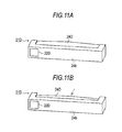
- an unlocking lever 21 B has a grip portion 24B that extends along the back surface 3s of the seatback 3 in a lateral direction of the seat.
- the unlocking lever 21 B has a turning axis L that extends vertically along the back surface 3s of the seatback 3.
- a control switch 22B is provided on a design surface 24b of the grip portion 24B of the unlocking lever 21 B.
- a pull type unlocking lever 21C may be used, a grip portion 24C of which is pulled toward the front side during an unlocking operation.
- a grip type unlocking lever 21 D may be used, in which when a grip portion 24D is squeezed, the shape of the grip portion 24D is changed, and as a result, an unlocking operation is completed.
- a control switch 22C of the unlocking lever 21C is provided on the design surface 24b of the grip portion 24C
- a control switch 22D of the unlocking lever 21 D is provided on the design surface 24b of the grip portion 24D. Since the grip portions 24C and 24D are disposed in such a manner as to extend along the back surface 3s of the seatback 3, it is possible to obtain the same effects as in the above-mentioned embodiment.
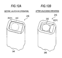
- an unlocking lever 21 E may include a limiting mechanism 30 that can limit the operation of a control switch 22E until an unlocking operation of the unlocking lever 21 E is performed. That is, in the configuration of the unlocking lever 21 E, when the unlocking lever 21 E is not operated, the control switch 22E is covered and hidden with a flexible plate-like cover member 31. When an unlocking operation of the unlocking lever 21 E is performed, the cover member 31 is drawn into a grip portion 24E.
- the limiting mechanism 30 is configured in such a manner that the control switch 22E is brought into an operable state as a result.
- a push switch is used as the control switch, it is possible to obtain the limiting mechanism 30 having the same function by locking a push portion (a push button) into a non-displaceable state until an unlocking operation of the unlocking lever is performed.
- the turning link 11 is provided as a support member for the seat 1.
- the turning link 11 is driven by the actuator 13.
- this disclosure is not limited to that configuration in the embodiment, and for example, the rear seat leg 5b may also act as the turning link.
- the type of the link mechanism formed by the support member is not necessarily limited to the turning link.
Landscapes
- Engineering & Computer Science (AREA)
- Aviation & Aerospace Engineering (AREA)
- Transportation (AREA)
- Mechanical Engineering (AREA)
- Human Computer Interaction (AREA)
- Seats For Vehicles (AREA)
Abstract
Description
- This disclosure relates to a seat apparatus for a vehicle.
- In the related art, there is a seat apparatus that can retract a seat in a concave retraction portion in a vehicle floor in a state where the seat is folded. For example, a seat apparatus disclosed in
JP 2007-186105A - For example, a seat apparatus disclosed in Japanese Patent No.
4602874 - A large amount of force is required for deploying and folding the seat, and in contrast, it is possible to unfix (unlock) the seat from the vehicle floor with a relatively small amount of force. For this reason, it is considered that the size of the apparatus is reduced by implementing a manual release of the locking. However, in the related art, a control switch of an actuator is provided on a vehicle body in many cases. For this reason, there is a problem in that when a manual release of the locking is simply implemented, user-friendliness deteriorates.
- That is, when the simplification of a configuration is taken into consideration, an unlocking lever of a locking device is preferably provided on the seat which is a moving body. Accordingly, in a case where the control switch of the actuator and the unlocking lever of the locking device are disposed separately from each other, there is a problem in that it may be difficult for a user to verify an unlocked state when a deployment operation and a folding operation start by the driving of the motor. Therefore, there is room for improvement in this regard.
- Thus, a need exists for a retractable seat apparatus for a vehicle with a simple configuration, which provides good user-friendliness.
- It is preferable that a seat apparatus for a vehicle according to an aspect of this disclosure includes: an unlocking lever that is operated so as to unfix a seat from a vehicle floor; and a control switch that is operated in order for the seat to switch between a deployed state in which the seat is supported on the vehicle floor and a folded state in which the seat is retracted in a concave retraction portion of the vehicle floor, when a support member of the seat is driven via the driving of an actuator, in which the unlocking lever is preferably provided in a back surface of a seatback which is disposed at an opening end of the concave retraction portion when the seatback is folded forward and the seat is retracted and the control switch is provided integrally with the unlocking lever.
- After an unlocking operation is performed, when a user takes their hands off the unlocking lever, a locking device may be locked (be brought into a teeth engagement state) again due to the weight of the seat or the like. However, in this configuration, it is possible to operate the control switch in a state where the unlocking lever is unlocked. As a result, it is possible to more reliably start the driving of the seat via an actuator in a state where the seat is unfixed from the vehicle floor. Accordingly, it is possible to prevent a retry operation originating from the teeth engagement of the locking device, and it is possible to realize good user-friendliness.
- In the seat apparatus for a vehicle according to the aspect of this disclosure, it is preferable that the control switch is a momentary switch.
- In this configuration, when the operation of the control switch is stopped, the actuator stops quickly. Accordingly, it is possible to prevent an occurrence of pinching of the seat associated with a deployment operation and a folding operation of the seat. Since the control switch is provided integrally with the unlocking lever, it is possible to operate the control switch continuously from the unlocking operation without a pause. Accordingly, it is possible to smoothly complete the switching of the seat between the deployed state and the folded state.
- In the seat apparatus for a vehicle according to the aspect of this disclosure, it is preferable that the unlocking lever is provided with a grip portion that a user grips so as to operate the unlocking lever, and the control switch is provided at a position in which a user can operate the control switch while gripping the grip portion.
- In this configuration, it is possible to improve user-friendliness of the unlocking lever. Since the control switch is provided at the position in which a user can operate the control switch while gripping the grip portion, it is possible to improve user-friendliness of the control switch.
- In the seat apparatus for a vehicle according to the aspect of this disclosure, it is preferable that the unlocking lever extends along the back surface of the seatback, and can unfix the seat from the vehicle floor via the turning, the pulling or the gripping of the unlocking lever.
- In this configuration, the unlocking lever is disposed substantially orthogonal to the direction in which the seatback is folded and is pulled upright. Accordingly, a user's hand can easily follow a displacement of the unlocking lever associated with the deployment operation and the folding operation of the seat. As a result, it is possible to realize better user-friendliness.
- In the seat apparatus for a vehicle according to the aspect of this disclosure, it is preferable that the seatback is manually folded forward and pulled upright.
- In this configuration, since the unlocking lever is used as an operation handle, it is possible to easily perform the forward folding operation and the upright pulling operation.
- In the seat apparatus for a vehicle according to the aspect of this disclosure, it is preferable that the seat apparatus further includes a forward folding mechanism that can fold the seatback forward while the seat is on the way to the concave retraction portion by releasing restriction of the tilting of the seatback in interconnection with the support member, when the seat is folded.
- In this configuration, a specific unlocking operation is not required to be performed, and the seatback can be folded on a seat cushion while being folded forward. Since the restriction of tilt is released during the movement of the seat, it is possible to decrease a change in the position of the unlocking lever (and the control switch) when the folding operation starts. Accordingly, after the unlocking lever is unlocked, it is possible to smoothly operate the control switch. As a result, it is possible to realize better user-friendliness.
- In the seat apparatus for a vehicle according to the aspect of this disclosure, it is preferable that the support member forms a link mechanism that moves the seat to the concave retraction portion while the seat makes an arc-shaped locus as the seat moves rearward, when the seat is folded, and the forward folding mechanism preferably releases the restriction of the tilting of the seatback at an apex position of the locus of the seat.
- In this configuration, after the seatback passes the apex position of the locus of the seat, the seatback is folded forward in a movement region in which the seat (the seat cushion) supported by the support member is considerably displaced rearward. Accordingly, a rearward displacement of the unlocking lever associated with the rearward movement of the seat can be cancelled out by a forward displacement of the seatback associated with the forward folding operation thereof. That is, it is possible to prevent a change in the position of the unlocking lever in a longitudinal direction of a vehicle, and a user's hand can easily follow the unlocking lever. As a result, it is possible to more smoothly fold the seatback forward via a manual operation in which the unlocking lever is used as an operation handle.
- In the seat apparatus for a vehicle according to the aspect of this disclosure, it is preferable that the seat apparatus further includes a limiting mechanism that can limit the operation of the control switch until an unlocking operation of the unlocking lever is performed.
- In this configuration, it is possible to more reliably start the driving of the seat via the actuator in a state where the seat is unfixed from the vehicle floor. Accordingly, it is possible to prevent a retry operation originating from the teeth engagement of the locking device, and it is possible to realize good user-friendliness.
- According to the aspect of this disclosure, it is possible to simplify the configuration by implementing a manual release of the locking, and to ensure good user-friendliness.
- The foregoing and additional features and characteristics of this disclosure will become more apparent from the following detailed description considered with the reference to the accompanying drawings, wherein:
-
Fig. 1 is a side view of a seat apparatus (in a deployed state); -
Fig. 2 is a side view of the seat apparatus (in a folded state); -
Figs. 3A and 3B are views illustrating a transition of the state of the seat apparatus; -
Fig. 4 is a perspective view of the seat apparatus (in a deployed state); -
Fig. 5 is a perspective view of the seat apparatus (in a folded state); -
Fig. 6A is a perspective view of an unlocking lever, andFigs. 6B and 6C are plan views of the unlocking lever; -
Fig. 7 is a side view of the unlocking lever; -
Fig. 8 is a view illustrating a locus of a seat during a folding operation; -
Fig. 9 is a perspective view illustrating another example of the unlocking lever; -
Fig. 10 is a perspective view illustrating another example of the unlocking lever; -
Figs. 11A and 11B are perspective views illustrating another example of the unlocking lever; and -
Figs. 12A and 12B are perspective views illustrating another example of the unlocking lever. - Hereinafter, an embodiment of a seat apparatus for a vehicle will be described with reference to the accompanying drawings.
- As illustrated in
Figs. 1 and2 , a seat for avehicle 1 includes aseat cushion 2, and aseatback 3 that is provided in a rear end portion of theseat cushion 2. In the embodiment,seat legs seat cushion 2, and support theseat cushion 2 above avehicle floor 4. Ahead rest 6 is provided in an upper end portion of theseatback 3. Areclining device 7 is provided between theseat cushion 2 and theseatback 3, and can adjust the tilt angle of theseatback 3 with respect to theseat cushion 2 using a motor (not illustrated) as a drive source. - In the embodiment, the
seat 1 is provided with alocking device 8 that can fix and unfix theseat 1 from thevehicle floor 4. Specifically, thelocking device 8 has a well-known configuration including a latch mechanism (not illustrated) that engages and disengages with respect to a striker (not illustrated), and is provided in a lower end portion of each of theseat legs seat apparatus 10 is formed, which can retract theseat 1 in aconcave retraction portion 9 of thevehicle floor 4 in a state where theseat 1 is folded, based on the function of thelocking device 8. - Specifically, in the embodiment, the
seat apparatus 10 includes a turninglink 11 that is turnably connected to each of abottom portion 9a of theconcave retraction portion 9 and theseat cushion 2. In a vehicle of the embodiment, theconcave retraction portion 9 is formed on a rear side (on the right side inFigs. 1 and2 ) of aseat deployment portion 12 that is set in thevehicle floor 4. An end of the turninglink 11 is connected to a rear end of theseat cushion 2, and the other end of the turninglink 11 is connected to thebottom portion 9a of theconcave retraction portion 9, specifically, a front end portion of thebottom portion 9a. - In the embodiment, an
actuator 13 is provided inside theseat cushion 2, and drives the turninglink 11 using a motor (not illustrated) as a drive source. Aforward folding mechanism 15 is provided in thereclining device 7 that is provided between theseat cushion 2 and theseatback 3 as described above, and theforward folding mechanism 15 can release restriction of the tilting of theseatback 3, and fold theseatback 3 forward. - That is, in the configuration of the
seat apparatus 10 of the embodiment, as illustrated inFigs. 1 to 3B , when the turninglink 11 turns by virtue of a drive force of theactuator 13, theseat cushion 2 supported by the turninglink 11 moves between theseat deployment portion 12 and theconcave retraction portion 9. In the embodiment, theforward folding mechanism 15 is connected to the turninglink 11 via a wire cable (not illustrated). Accordingly, theforward folding mechanism 15 is configured in such a manner as to release the restriction of the tilting of theseatback 3 during a folding operation in which theseat 1 is retracted in theconcave retraction portion 9. - In the embodiment, when the
seat cushion 2 moves into theconcave retraction portion 9, the respective base ends of theseat legs seat legs seat cushion 2. Theseatback 3 is manually folded forward and pulled upright. In the embodiment, as illustrated inFig. 2 , theseatback 3 is disposed at an opening end of theconcave retraction portion 9 when being folded forward and being folded on theseat cushion 2. - In the embodiment, as illustrated in
Figs. 4 and5 , theseat apparatus 10 includes an unlockinglever 21 that is operated so as to unfix theseat 1 fixed by thelocking device 8, and acontrol switch 22 of theactuator 13, which is operated in order for theseat 1 to switch between the deployed state in which theseat 1 is supported on thevehicle floor 4 and the folded state in which theseat 1 is retracted in theconcave retraction portion 9. In the embodiment, the unlockinglever 21 is provided on aback surface 3s of theseatback 3. Thecontrol switch 22 is provided integrally with the unlockinglever 21. - Specifically, in the embodiment, as illustrated in
Fig. 6A , the unlockinglever 21 has a substantially quadrangular bar (shaft)-shaped appearance. The unlockinglever 21 has agrip portion 24 at an end thereof, which a user grips so as to operate the unlockinglever 21. Thecontrol switch 22 is provided on anend surface 24a of thegrip portion 24. - As illustrated in
Figs. 4 and5 , aconcave accommodation portion 25 for accommodating the unlockinglever 21 is formed on an inner side of theback surface 3s of theseatback 3. In the embodiment, theconcave accommodation portion 25 is formed at a position higher than a vertical middle position on theback surface 3s of theseatback 3. In the embodiment, the unlockinglever 21 is disposed inside theconcave accommodation portion 25 in a state where thegrip portion 24 extends vertically along theback surface 3s of theseatback 3. In addition, a base end portion of the unlockinglever 21 passes through a lower side wall of theconcave accommodation portion 25, and is connected to thelocking device 8 via a wire cable (not illustrated) built into theseat 1. In theseat apparatus 10 of the embodiment, an unlocking operation of the unlockinglever 21 is transmitted to thelocking device 8 via this wire cable. - Specifically, in the embodiment, as illustrated in
Fig. 7 , a turning operation (in a counter-clockwise direction inFig. 7 ) of the unlockinglever 21 is performed in such a manner that thegrip portion 24 disposed inside theconcave accommodation portion 25 is tilted along theback surface 3s of theseatback 3. Accordingly, the wire cable connected to the base end portion of the unlockinglever 21 is pulled, and thereby thelocking device 8 is unlocked. That is, theseat 1 is unfixed from thevehicle floor 4. - In the embodiment, as illustrated in
Figs. 6B and 6C , thecontrol switch 22 is a push switch which has twoindependent operation portions Figs. 6B and 6C ), when a user faces theback surface 3s of theseatback 3 in which the unlockinglever 21 is provided. - Specifically, in the embodiment, as illustrated in
Fig. 6B , when a user presses thefirst operation portion 22a that is positioned on the front side (the lower side inFig. 6B ) when facing theback surface 3s of theseatback 3, thecontrol switch 22 outputs a control signal to theactuator 13, the control signal being indicative of driving theturning link 11 and folding theseat 1. As illustrated inFig. 6C , when a user presses thesecond operation portion 22b that is positioned on the rear side (the upper side inFig. 6C ) when facing theback surface 3s of theseatback 3, thecontrol switch 22 outputs a control signal to theactuator 13, the control signal being indicative of deploying theseat 1. In addition, in the embodiment, thecontrol switch 22 is a momentary switch that continuously outputs (is turned ON) the related control signal only during the continued pressing operation. In the embodiment, theseat apparatus 10 controls theactuator 13 based on the operation of thecontrol switch 22. - More specifically, in the configuration of the
seat apparatus 10 of the embodiment, as illustrated inFig. 8 , due to the turning of the turninglink 11, the seat 1 (the seat cushion 2) supported by the turninglink 11 is folded (and is deployed) while making an arc-shaped locus. In the configuration of theforward folding mechanism 15 of the embodiment, while a folding operation is performed, a wire cable (not illustrated) is pulled, which is interposed between theforward folding mechanism 15 and the turninglink 11, and thereby the restriction of the tilting of theseatback 3 is released at an apex position (a movement position illustrated by the solid line inFig. 8 ) of the locus of the seat. - Subsequently, an operation of the
seat apparatus 10 with this configuration will be described. - When the deployed seat 1 (refer to
Fig. 1 ) supported on thevehicle floor 4 is retracted in theconcave retraction portion 9 while being folded (refer toFig. 2 ), first, a user turns the unlockinglever 21 that is provided in theback surface 3s of the seatback 3 (refer toFig. 7 ). The user turns the unlockinglever 21 while gripping thegrip portion 24. Accordingly, in the embodiment, thelocking device 8 at each of theseat legs seat 1 is unfixed from thevehicle floor 4. - After the unlocking operation is performed, the user presses the
control switch 22 on theend surface 24a of thegrip portion 24, and thereby the turning link (a support member) 11 turns by virtue of a drive force of theactuator 13, and theseat cushion 2 supported by the turninglink 11 moves from theseat deployment portion 12 to theconcave retraction portion 9. Specifically, thefirst operation portion 22a is pressed (refer toFig. 6B ). In theseat apparatus 10 of the embodiment, when thefirst operation portion 22a of thecontrol switch 22 is continuously pressed, theseat cushion 2 supported by the turninglink 11 is retracted in theconcave retraction portion 9. - In the embodiment, since the turning
link 11 and theforward folding mechanism 15 are interconnected with each other, the restriction of the tilting of theseatback 3 is released while theseat cushion 2 is on the way to theconcave retraction portion 9. Accordingly, it is possible to manually fold theseatback 3 forward. - Here, as illustrated in
Fig. 8 , when theseatback 3 is folded forward, an upper end of theseatback 3 moves forward. InFig. 8 , each of points P1 to P7 indicate the position of the upper end of the seatback 3 (the head rest 6) when theseat 1 is folded (and is deployed). - In the
seat apparatus 10 of the embodiment, this point is taken into consideration, theforward folding mechanism 15 releases the restriction of the tilting of theseatback 3 at the apex position of the locus of the seat. That is, theseat cushion 2 supported by the turninglink 11 is accommodated in theconcave retraction portion 9 while moving rearward. Accordingly, after theseatback 3 passes the apex position of the locus of the seat, theseatback 3 is folded forward in a movement region in which theseat cushion 2 supported by the turninglink 11 is considerably displaced rearward, and thereby a rearward displacement of the unlockinglever 21 associated with the rearward movement of theseat cushion 2 can be cancelled out by a forward displacement of theseatback 3 associated with the forward folding operation. Accordingly, in the embodiment, it is possible to prevent a change in the position of the unlockinglever 21 in a longitudinal direction of the vehicle. - In the embodiment, the
forward folding mechanism 15 is configured in such a manner as to assist in folding theseatback 3 forward by biasing theseatback 3 forward using a spring member (not illustrated). Theseatback 3 is folded on theseat cushion 2 via the forward folding operation, and is disposed at the opening end of theconcave retraction portion 9. Accordingly, in theseat apparatus 10 of the embodiment, theseat 1 is retracted in theconcave retraction portion 9 while the unlockinglever 21 faces the interior of the vehicle, the unlockinglever 21 being provided in theback surface 3s of theseatback 3. - In contrast, a user presses the
second operation portion 22b of thecontrol switch 22 provided in the unlockinglever 21, when deploying theseat 1 on thevehicle floor 4, theseat 1 being retracted in theconcave retraction portion 9 while being in a folded state (refer toFig. 6C ). Accordingly, the turninglink 11 turns by virtue of a drive force of the actuator 13 (in a counter-clockwise direction inFigs. 1 to 3B ), and thereby theseat cushion 2 supported by the turninglink 11 moves from theconcave retraction portion 9 to theseat deployment portion 12. - At this time, the
seatback 3 is manually pulled upright, and the tilting of theseatback 3 is limited at a stage in which theseatback 3 is pulled upright to a predetermined position. Thesecond operation portion 22b of thecontrol switch 22 is continuously pressed, and theseat cushion 2 supported by the turninglink 11 moves to theseat deployment portion 12. Accordingly, in the configuration of theseat apparatus 10 of the embodiment, thelocking device 8 at each of theseat legs seat 1 is fixed to thevehicle floor 4. As a result, theseat 1 is deployed so that an occupant can sit on theseat 1. - According to the embodiment, it is possible to obtain the following effects.
- (1) The
seat apparatus 10 includes the unlockinglever 21 that is operated so as to unfix theseat 1 from thevehicle floor 4. Theseat apparatus 10 includes thecontrol switch 22 that is operated in order for the seat 1 (theseat 1 being supported by the turning link 11) to switch between the deployed state in which theseat 1 is supported on thevehicle floor 4 and the folded state in which theseat 1 is retracted in theconcave retraction portion 9, via the turning of the turninglink 11 using a drive force of theactuator 13. The unlockinglever 21 is provided in theback surface 3s of theseatback 3 which is disposed at the opening end of theconcave retraction portion 9 when theseatback 3 is folded forward and theseat 1 is retracted. Thecontrol switch 22 is provided integrally with the unlockinglever 21. - After an unlocking operation is performed, when a user takes their hands off the unlocking
lever 21, thelocking device 8 may be locked (be brought into a teeth engagement state) again due to the weight of theseat 1 or the like. However, in this configuration, it is possible to operate thecontrol switch 22 in a state where the unlockinglever 21 is unlocked. As a result, it is possible to more reliably start the driving of the seat via theactuator 13 in a state where theseat 1 is unfixed from thevehicle floor 4. Accordingly, it is possible to prevent a retry operation originating from the teeth engagement of thelocking device 8, and it is possible to realize good user-friendliness. - (2) The
control switch 22 is a momentary switch that is continuously turned ON only while thecontrol switch 22 is continuously operated. - In this configuration, when the operation of the
control switch 22 is stopped, theactuator 13 stops quickly. Accordingly, it is possible to prevent an occurrence of pinching of the seat associated with the deployment operation and the folding operation of the seat. Since thecontrol switch 22 is provided integrally with the unlockinglever 21, it is possible to operate thecontrol switch 22 continuously from the unlocking operation without a pause. Accordingly, it is possible to smoothly complete the switching of theseat 1 between a deployed state and a folded state. - (3) The unlocking
lever 21 is provided with thegrip portion 24 that a user grips so as to operate the unlockinglever 21. Thecontrol switch 22 is provided on theend surface 24a of thegrip portion 24. - In this configuration, it is possible to improve user-friendliness of the unlocking
lever 21. Since thecontrol switch 22 is provided at the position in which a user can operate thecontrol switch 22 while gripping thegrip portion 24, it is possible to improve user-friendliness of thecontrol switch 22. In addition, it is possible to continuously operate thecontrol switch 22 that is a momentary switch. - (4) The unlocking
lever 21 is a turning lever that extends along theback surface 3s of theseatback 3. - In this configuration, the unlocking
lever 21 is disposed substantially orthogonal to a direction in which theseatback 3 is folded and is pulled upright. Accordingly, a user's hand can easily follow a displacement of the unlockinglever 21 associated with the deployment operation and the folding operation of theseat 1. As a result, it is possible to realize better user-friendliness. - (5) The
seatback 3 is manually folded forward and pulled upright. - That is, in this configuration, since the unlocking
lever 21 is used as an operation handle, it is possible to easily perform the forward folding operation and the upright pulling operation. Since the unlockinglever 21 is disposed substantially orthogonal to the direction in which theseatback 3 is folded and is pulled upright, it is possible to more easily perform the forward folding operation and the upright pulling operation. Since the unlockinglever 21 is provided with thegrip portion 24, it is possible to more easily perform the forward folding operation and the upright pulling operation. - Since the
control switch 22 is provided integrally with the unlockinglever 21, it is possible to continuously operate thecontrol switch 22 even during the course of the manual forward folding operation and the manual upright pulling operation. That is, it is possible to manually perform the forward folding operation and the upright pulling operation in parallel with the driving of the seat via theactuator 13. Accordingly, it is possible to realize good user-friendliness. - (6) The
seat apparatus 10 includes theforward folding mechanism 15 that can fold theseatback 3 forward while the seat 1 (the seat cushion 2) is on the way to theconcave retraction portion 9 by releasing the restriction of the tilting of theseatback 3 in interconnection with the turninglink 11 when theseat 1 is folded. - In this configuration, a specific unlocking operation is not required to be performed, and the
seatback 3 can be folded on theseat cushion 2 while being folded forward. Since the restriction of tilt is released during the movement of theseat 1, it is possible to decrease a change in the position of the unlocking lever 21 (and the control switch 22) when the folding operation starts. Accordingly, after the unlockinglever 21 is unlocked, it is possible to smoothly operate thecontrol switch 22. As a result, it is possible to realize better user-friendliness. - (7) When the folding operation is performed, the turning
link 11 moves theseat 1 to theconcave retraction portion 9 while theseat 1 makes an arc-shaped locus along with the rearward movement of theseat 1. Theforward folding mechanism 15 releases the restriction of the tilting of theseatback 3 at the apex position of the locus of the seat. - In this configuration, after the
seatback 3 passes the apex position of the locus of the seat, theseatback 3 is folded forward in the movement region in which theseat cushion 2 supported by the turninglink 11 is considerably displaced rearward. Accordingly, a rearward displacement of the unlockinglever 21 associated with the rearward movement of theseat cushion 2 can be cancelled out by a forward displacement of theseatback 3 associated with the forward folding operation thereof. That is, it is possible to prevent a change in the position of the unlockinglever 21 in the longitudinal direction of the vehicle, and a user's hand can easily follow the unlockinglever 21. As a result, it is possible to more smoothly fold theseatback 3 forward and operate thecontrol switch 22 via a manual operation in which the unlockinglever 21 is used as an operation handle. - (8) The unlocking
lever 21 is provided at a position higher than the vertical middle position on theback surface 3s of theseatback 3. In this configuration, it is possible to more easily fold theseatback 3 forward and pull theseatback 3 upright via a manual operation in which the unlockinglever 21 is used as an operation handle. - (9) In the
control switch 22, when a user faces theback surface 3s of theseatback 3, thefirst operation portion 22a for a folding operation is disposed on the front side, and thesecond operation portion 22b for a deployment operation is disposed on the rear side. In this configuration, it is possible to intuitively perform an appropriate control of the actuator corresponding to the intended deployment and folding operations. Accordingly, it is possible to realize good user-friendliness. - The following changes may be made to this embodiment.
- In the above-mentioned embodiment, the
locking device 8 and the unlockinglever 21 are connected to each other via the wire cable, and the turninglink 11 and theforward folding mechanism 15 are connected to each other via the wire cable. However, the connection structure may be arbitrarily changed, and for example, a rod or a link may be used for connection therebetween. In addition, the configuration of thelocking device 8 may be arbitrarily changed. For example, thelocking device 8 may not include the latch mechanism. Theseat cushion 2 may not necessarily be fixed by theseat legs vehicle floor 4. The configuration of theforward folding mechanism 15 may be arbitrarily changed, and for example, theforward folding mechanism 15 may not have a forward biasing mechanism via a spring member. - In the above-mentioned embodiment, the
forward folding mechanism 15 is provided in thereclining device 7 that uses the motor as a drive source. However, the drive source is not limited to the motor, and thereclining device 7 may be manually operated. Theseatback 3 may be folded forward by changing a tilt angle via the driving of the motor. - In the above-mentioned embodiment, when the folding operation is performed, the unlocking
lever 21 is operated so as to unfix theseat 1 from theseat deployment portion 12 that is provided in thevehicle floor 4. However, this disclosure is not limited to that configuration in the embodiment, and also when theseat 1 is retracted in theconcave retraction portion 9 while being in a folded state, theseat 1 is fixed to theconcave retraction portion 9 via thelocking device 8. Also when the deployment operation is performed, the unlockinglever 21 may be operated so as to unfix theseat 1 from theconcave retraction portion 9. - In the above-mentioned embodiment, a push type momentary switch is used as the
control switch 22 that has the twoindependent operation portions control switch 22 may be arbitrarily changed. For example, a slide switch, or a capacitance type touch switch may be used. Thecontrol switch 22 may not necessarily be a momentary switch. In addition, when thecontrol switch 22 is operated once, thecontrol switch 22 may be turned ON until the deployment operation and the folding operation of theseat 1 are completed. Thecontrol switch 22 may not have a plurality of operation portions. The disposition of thecontrol switch 22 on the unlockinglever 21 may be arbitrarily changed. - In the above-mentioned embodiment, the unlocking
lever 21 is a turning lever which extends vertically along theback surface 3s of theseatback 3, and a turning operation of which is performed in such a manner that thegrip portion 24 is tilted along theback surface 3s of theseatback 3. Thecontrol switch 22 is provided on theend surface 24a of thegrip portion 24. - However, this disclosure is not limited to that configuration in the embodiment, and for example, as illustrated in
Fig. 9 , an unlockinglever 21 B has agrip portion 24B that extends along theback surface 3s of theseatback 3 in a lateral direction of the seat. The unlockinglever 21 B has a turning axis L that extends vertically along theback surface 3s of theseatback 3. In addition, acontrol switch 22B is provided on adesign surface 24b of thegrip portion 24B of the unlockinglever 21 B. When an unlocking operation is performed, thegrip portion 24B turns toward the front side, that is, in the direction in which theseatback 3 is pulled upright. It is possible to obtain the same effects as in the above-mentioned embodiment even using such a turning lever. - As illustrated in
Fig. 10 , a pulltype unlocking lever 21C may be used, agrip portion 24C of which is pulled toward the front side during an unlocking operation. As illustrated inFigs. 11A and 11B , a griptype unlocking lever 21 D may be used, in which when agrip portion 24D is squeezed, the shape of thegrip portion 24D is changed, and as a result, an unlocking operation is completed. Acontrol switch 22C of the unlockinglever 21C is provided on thedesign surface 24b of thegrip portion 24C, and acontrol switch 22D of the unlockinglever 21 D is provided on thedesign surface 24b of thegrip portion 24D. Since thegrip portions back surface 3s of theseatback 3, it is possible to obtain the same effects as in the above-mentioned embodiment. - As illustrated in
Figs. 12A and 12B , an unlockinglever 21 E may include a limitingmechanism 30 that can limit the operation of acontrol switch 22E until an unlocking operation of the unlockinglever 21 E is performed. That is, in the configuration of the unlockinglever 21 E, when the unlockinglever 21 E is not operated, thecontrol switch 22E is covered and hidden with a flexible plate-like cover member 31. When an unlocking operation of the unlockinglever 21 E is performed, thecover member 31 is drawn into agrip portion 24E. The limitingmechanism 30 is configured in such a manner that thecontrol switch 22E is brought into an operable state as a result. - For example, in a case where a push switch is used as the control switch, it is possible to obtain the limiting
mechanism 30 having the same function by locking a push portion (a push button) into a non-displaceable state until an unlocking operation of the unlocking lever is performed. - In this configuration, it is possible to more reliably start the driving of the seat via the
actuator 13 in a state where theseat 1 is unfixed from thevehicle floor 4. Accordingly, it is possible to prevent a retry operation originating from the teeth engagement of thelocking device 8, and it is possible to realize good user-friendliness. - In the above-mentioned embodiment, the turning
link 11 is provided as a support member for theseat 1. The turninglink 11 is driven by theactuator 13. However, this disclosure is not limited to that configuration in the embodiment, and for example, therear seat leg 5b may also act as the turning link. The type of the link mechanism formed by the support member is not necessarily limited to the turning link. - The following description is regarding technical ideas that can be obtained from the embodiments.
- (a) In the seat apparatus for a vehicle, the unlocking lever is provided at a position higher than the vertical middle position on the back surface of the seatback. In this configuration, it is possible to more easily fold the seatback forward and pull the seatback upright via a manual operation in which the unlocking lever is used as an operation handle.
- (b) In the seat apparatus for a vehicle, the control switch includes the first operation portion and the second operation portion which are respectively positioned on the front side and the rear side when a user faces the back surface of the seatback. When the first operation portion is operated, the actuator drives the support member in order for the seat to be folded, and when the second operation portion is operated, the actuator drives the support member in order for the seat to be deployed. In this configuration, it is possible to intuitively perform an appropriate control of the actuator corresponding to the intended deployment and folding operations. Accordingly, it is possible to realize good user-friendliness.
- The principles, preferred embodiment and mode of operation of the present invention have been described in the foregoing specification. However, the invention which is intended to be protected is not to be construed as limited to the particular embodiments disclosed. Further, the embodiments described herein are to be regarded as illustrative rather than restrictive. Variations and changes may be made by others, and equivalents employed. Accordingly, it is expressly intended that all such variations, changes and equivalents which fall within the scope of the present invention as defined in the claims, be embraced thereby.
Claims (10)
- A seat apparatus (10) for a vehicle comprising:an unlocking lever (21, 21B, 21C, 21D, 21E) configured to be operated so as to unfix a seat (1) from a vehicle floor (4); anda control switch (22, 22B, 22C, 22D, 22E) configured to be operated in order for the seat (1) to switch between a deployed state in which the seat (1) is supported on the vehicle floor (4) and a folded state in which the seat (1) is retracted in a concave retraction portion (9) of the vehicle floor (4), when a support member (11) of the seat is driven via the driving of an actuator (13),wherein the unlocking lever is provided in a back surface (3s) of a seatback (3) which is disposed at an opening end of the concave retraction portion (9) when the seatback (3) is folded forward and the seat (1) is retracted, and the control switch is provided integrally with the unlocking lever.
- The seat apparatus for a vehicle according to claim 1,
wherein the control switch (22, 22B, 22C, 22D, 22E) is a momentary switch. - The seat apparatus for a vehicle according to claim 1 or 2,
wherein the unlocking lever (21, 21B, 21C, 21D, 21E) is provided with a grip portion (24, 24B, 24C, 24D, 24E) configured to be gripped by a user so as to operate the unlocking lever, and
wherein the control switch (22, 22B, 22C, 22D, 22E) is provided at a position in which a user can operate the control switch while gripping the grip portion. - The seat apparatus for a vehicle according to any one of claims 1 to 3, wherein the unlocking lever (21, 21B, 21C, 21D, 21E) extends along the back surface (3s) of the seatback (3), and can unfix the seat (1) from the vehicle floor (4) via the turning, the pulling or the gripping of the unlocking lever.
- The seat apparatus for a vehicle according to any one of claims 1 to 4, wherein the seatback (3) is configured to be manually folded forward and pulled upright.
- The seat apparatus for a vehicle according to claim 5 further comprising:a forward folding mechanism (15) that can fold the seatback (3) forward while the seat (1) is on the way to the concave retraction portion (9) by releasing restriction of the tilting of the seatback (3) in interconnection with the support member (11), when the seat (1) is folded.
- The seat apparatus for a vehicle according to claim 6,
wherein the support member (11) forms a link mechanism configured to move the seat (1) to the concave retraction portion (9) while the seat (1) makes an arc-shaped locus as the seat (1) moves rearward, when the seat (1) is folded, and
wherein the forward folding mechanism (15) is configured to release the restriction of the tilting of the seatback (3) at an apex position of the locus of the seat (1). - The seat apparatus for a vehicle according to any one of claims 1 to 7 further comprising:a limiting mechanism (30) that can limit the operation of the control switch (22, 22B, 22C, 22D, 22E) until an unlocking operation of the unlocking lever (21, 21B, 21C, 21 D, 21 E) is performed.
- The seat apparatus for a vehicle according to any one of claims 1 to 8,
wherein the unlocking lever (21, 21 B, 21C, 21 D, 21 E) is provided at a position higher than a vertical middle position on the back surface (3s) of the seatback (3). - The seat apparatus for a vehicle according to any one of claims 1 to 9,
wherein the control switch (22, 22B, 22C, 22D, 22E) includes a first operation portion (22a) and a second operation portion (22b) which are respectively positioned on a front side and a rear side, when a user faces the back surface (3s) of the seatback (3), and
wherein when the first operation portion (22a) is operated, the actuator is configured to drive the support member (11) in order for the seat (1) to be folded, and when the second operation portion (22b) is operated, the actuator is configured to drive the support member (11) in order for the seat (1) to be deployed.
Applications Claiming Priority (1)
| Application Number | Priority Date | Filing Date | Title |
|---|---|---|---|
| JP2014021400A JP6287286B2 (en) | 2014-02-06 | 2014-02-06 | Vehicle seat device |
Publications (2)
| Publication Number | Publication Date |
|---|---|
| EP2910410A1 true EP2910410A1 (en) | 2015-08-26 |
| EP2910410B1 EP2910410B1 (en) | 2017-05-10 |
Family
ID=52446316
Family Applications (1)
| Application Number | Title | Priority Date | Filing Date |
|---|---|---|---|
| EP15154136.4A Not-in-force EP2910410B1 (en) | 2014-02-06 | 2015-02-06 | Seat apparatus for vehicle |
Country Status (4)
| Country | Link |
|---|---|
| US (1) | US9381837B2 (en) |
| EP (1) | EP2910410B1 (en) |
| JP (1) | JP6287286B2 (en) |
| CN (1) | CN204547850U (en) |
Cited By (1)
| Publication number | Priority date | Publication date | Assignee | Title |
|---|---|---|---|---|
| ES2780937A1 (en) * | 2019-02-25 | 2020-08-27 | Seat Sa | Seat for a vehicle (Machine-translation by Google Translate, not legally binding) |
Families Citing this family (6)
| Publication number | Priority date | Publication date | Assignee | Title |
|---|---|---|---|---|
| JP6721441B2 (en) * | 2016-07-14 | 2020-07-15 | 株式会社ニフコ | Table unit |
| GB2566012B (en) * | 2017-08-24 | 2020-05-06 | Ford Global Tech Llc | Vehicle furniture system |
| US11731546B1 (en) * | 2020-07-13 | 2023-08-22 | Waymo Llc | Seat back release blocker |
| US12427898B2 (en) * | 2021-03-30 | 2025-09-30 | Ts Tech Co., Ltd. | Vehicle seat |
| CN113561862A (en) * | 2021-07-27 | 2021-10-29 | 东风柳州汽车有限公司 | Seat skeleton, car seat and car |
| KR102928018B1 (en) | 2023-11-22 | 2026-02-19 | 대원산업 주식회사 | Semi power pop-up seat |
Citations (6)
| Publication number | Priority date | Publication date | Assignee | Title |
|---|---|---|---|---|
| EP1493611A1 (en) * | 2003-06-30 | 2005-01-05 | HONDA MOTOR CO., Ltd. | Electric vehicle seat stowing structure |
| US20070046088A1 (en) * | 2005-08-30 | 2007-03-01 | Aisin Seiki Kabushiki Kaisha | Seat apparatus |
| JP2007186105A (en) | 2006-01-13 | 2007-07-26 | Toyota Boshoku Corp | Operation member arrangement structure for vehicle seat |
| US20080093875A1 (en) * | 2006-10-17 | 2008-04-24 | Tachi-S Co., Ltd. | Retractable vehicle seat of laterally folding type |
| JP4602874B2 (en) | 2005-08-30 | 2010-12-22 | アイシン精機株式会社 | Sheet device |
| US20110080027A1 (en) * | 2009-10-01 | 2011-04-07 | Toyota Boshoku Kabushiki Kaisha | Retractable seat for vehicle |
Family Cites Families (10)
| Publication number | Priority date | Publication date | Assignee | Title |
|---|---|---|---|---|
| US2668076A (en) * | 1951-10-17 | 1954-02-02 | J H Holan Corp | Locking-bolt operating structure |
| JPH01168533A (en) * | 1987-12-23 | 1989-07-04 | Nissan Motor Co Ltd | Rear seat back for automobile |
| JP3100110B2 (en) * | 1995-05-24 | 2000-10-16 | 新キャタピラー三菱株式会社 | Control lever lock device for construction machinery |
| US6106066A (en) * | 1999-08-30 | 2000-08-22 | Freedman Seating Company | Stowable cantilevered seat |
| JP4948917B2 (en) * | 2006-06-26 | 2012-06-06 | 本田技研工業株式会社 | Operating device for seat lock mechanism |
| EP2108541B1 (en) * | 2007-01-31 | 2011-02-23 | Toyota Boshoku Kabushiki Kaisha | Automobile seat stowage structure |
| EP2186672B1 (en) * | 2007-09-06 | 2012-12-19 | Toyota Shatai Kabushiki Kaisha | Seat device for vehicle |
| WO2010125677A1 (en) | 2009-04-30 | 2010-11-04 | トヨタ車体 株式会社 | Stowable seat |
| JP4785011B2 (en) * | 2009-08-21 | 2011-10-05 | トヨタ紡織株式会社 | Vehicle seat |
| US8313147B2 (en) * | 2010-04-21 | 2012-11-20 | Honda Motor Co., Ltd. | Seat latch assembly for a vehicle seat |
-
2014
- 2014-02-06 JP JP2014021400A patent/JP6287286B2/en not_active Expired - Fee Related
-
2015
- 2015-02-04 CN CN201520079594.XU patent/CN204547850U/en not_active Expired - Fee Related
- 2015-02-04 US US14/613,813 patent/US9381837B2/en not_active Expired - Fee Related
- 2015-02-06 EP EP15154136.4A patent/EP2910410B1/en not_active Not-in-force
Patent Citations (6)
| Publication number | Priority date | Publication date | Assignee | Title |
|---|---|---|---|---|
| EP1493611A1 (en) * | 2003-06-30 | 2005-01-05 | HONDA MOTOR CO., Ltd. | Electric vehicle seat stowing structure |
| US20070046088A1 (en) * | 2005-08-30 | 2007-03-01 | Aisin Seiki Kabushiki Kaisha | Seat apparatus |
| JP4602874B2 (en) | 2005-08-30 | 2010-12-22 | アイシン精機株式会社 | Sheet device |
| JP2007186105A (en) | 2006-01-13 | 2007-07-26 | Toyota Boshoku Corp | Operation member arrangement structure for vehicle seat |
| US20080093875A1 (en) * | 2006-10-17 | 2008-04-24 | Tachi-S Co., Ltd. | Retractable vehicle seat of laterally folding type |
| US20110080027A1 (en) * | 2009-10-01 | 2011-04-07 | Toyota Boshoku Kabushiki Kaisha | Retractable seat for vehicle |
Cited By (1)
| Publication number | Priority date | Publication date | Assignee | Title |
|---|---|---|---|---|
| ES2780937A1 (en) * | 2019-02-25 | 2020-08-27 | Seat Sa | Seat for a vehicle (Machine-translation by Google Translate, not legally binding) |
Also Published As
| Publication number | Publication date |
|---|---|
| US20150217662A1 (en) | 2015-08-06 |
| US9381837B2 (en) | 2016-07-05 |
| JP2015147503A (en) | 2015-08-20 |
| CN204547850U (en) | 2015-08-12 |
| JP6287286B2 (en) | 2018-03-07 |
| EP2910410B1 (en) | 2017-05-10 |
Similar Documents
| Publication | Publication Date | Title |
|---|---|---|
| EP2910410B1 (en) | Seat apparatus for vehicle | |
| CN101959715B (en) | Stowable vehicle seat | |
| JP5746336B2 (en) | Electromechanical push button vehicle seat actuation mechanism | |
| CN101821124B (en) | Stowable vehicle seat | |
| CN101511633B (en) | Operating lever for vehicle seat | |
| CN102143862B (en) | Misoperation prevention device and stowable seat for vehicles | |
| US8678501B2 (en) | Backrest folding mechanism for a vehicle seat | |
| CN101541586B (en) | Seat device for vehicle | |
| JP5164514B2 (en) | Vehicle storage seat | |
| KR101583966B1 (en) | Device of folding a seat for vehicle | |
| EP2269864A1 (en) | Stowable vehicle seat | |
| JP2007284021A (en) | Vehicle seat device | |
| US20100225151A1 (en) | Vehicle seat actuation mechanism | |
| JP4566152B2 (en) | Vehicle seat device | |
| KR101601509B1 (en) | Device of folding a seat for vehicle | |
| KR100803067B1 (en) | Rear seat walk-in device | |
| JP4353969B2 (en) | Car | |
| KR101607206B1 (en) | Walk-in memory apparatus of asymmetric seat track | |
| JP5589368B2 (en) | Vehicle seat device | |
| JP2007106292A (en) | Seat device with automatic storage structure for headrest | |
| CN110386041B (en) | Seat device for vehicle | |
| JP6711143B2 (en) | Seat device | |
| JP2013001176A (en) | Vehicle seat | |
| JP2009234370A (en) | Vehicular stowable seat | |
| JP3517138B2 (en) | Variable position and attitude device for automotive seats |
Legal Events
| Date | Code | Title | Description |
|---|---|---|---|
| PUAI | Public reference made under article 153(3) epc to a published international application that has entered the european phase |
Free format text: ORIGINAL CODE: 0009012 |
|
| AK | Designated contracting states |
Kind code of ref document: A1 Designated state(s): AL AT BE BG CH CY CZ DE DK EE ES FI FR GB GR HR HU IE IS IT LI LT LU LV MC MK MT NL NO PL PT RO RS SE SI SK SM TR |
|
| AX | Request for extension of the european patent |
Extension state: BA ME |
|
| 17P | Request for examination filed |
Effective date: 20160211 |
|
| RBV | Designated contracting states (corrected) |
Designated state(s): AL AT BE BG CH CY CZ DE DK EE ES FI FR GB GR HR HU IE IS IT LI LT LU LV MC MK MT NL NO PL PT RO RS SE SI SK SM TR |
|
| GRAP | Despatch of communication of intention to grant a patent |
Free format text: ORIGINAL CODE: EPIDOSNIGR1 |
|
| INTG | Intention to grant announced |
Effective date: 20170103 |
|
| GRAS | Grant fee paid |
Free format text: ORIGINAL CODE: EPIDOSNIGR3 |
|
| GRAJ | Information related to disapproval of communication of intention to grant by the applicant or resumption of examination proceedings by the epo deleted |
Free format text: ORIGINAL CODE: EPIDOSDIGR1 |
|
| GRAL | Information related to payment of fee for publishing/printing deleted |
Free format text: ORIGINAL CODE: EPIDOSDIGR3 |
|
| GRAR | Information related to intention to grant a patent recorded |
Free format text: ORIGINAL CODE: EPIDOSNIGR71 |
|
| GRAA | (expected) grant |
Free format text: ORIGINAL CODE: 0009210 |
|
| INTC | Intention to grant announced (deleted) | ||
| AK | Designated contracting states |
Kind code of ref document: B1 Designated state(s): AL AT BE BG CH CY CZ DE DK EE ES FI FR GB GR HR HU IE IS IT LI LT LU LV MC MK MT NL NO PL PT RO RS SE SI SK SM TR |
|
| INTG | Intention to grant announced |
Effective date: 20170403 |
|
| REG | Reference to a national code |
Ref country code: GB Ref legal event code: FG4D |
|
| REG | Reference to a national code |
Ref country code: AT Ref legal event code: REF Ref document number: 891935 Country of ref document: AT Kind code of ref document: T Effective date: 20170515 Ref country code: CH Ref legal event code: EP |
|
| REG | Reference to a national code |
Ref country code: IE Ref legal event code: FG4D |
|
| REG | Reference to a national code |
Ref country code: DE Ref legal event code: R096 Ref document number: 602015002562 Country of ref document: DE |
|
| REG | Reference to a national code |
Ref country code: NL Ref legal event code: MP Effective date: 20170510 |
|
| REG | Reference to a national code |
Ref country code: LT Ref legal event code: MG4D |
|
| REG | Reference to a national code |
Ref country code: AT Ref legal event code: MK05 Ref document number: 891935 Country of ref document: AT Kind code of ref document: T Effective date: 20170510 |
|
| PG25 | Lapsed in a contracting state [announced via postgrant information from national office to epo] |
Ref country code: HR Free format text: LAPSE BECAUSE OF FAILURE TO SUBMIT A TRANSLATION OF THE DESCRIPTION OR TO PAY THE FEE WITHIN THE PRESCRIBED TIME-LIMIT Effective date: 20170510 Ref country code: ES Free format text: LAPSE BECAUSE OF FAILURE TO SUBMIT A TRANSLATION OF THE DESCRIPTION OR TO PAY THE FEE WITHIN THE PRESCRIBED TIME-LIMIT Effective date: 20170510 Ref country code: AT Free format text: LAPSE BECAUSE OF FAILURE TO SUBMIT A TRANSLATION OF THE DESCRIPTION OR TO PAY THE FEE WITHIN THE PRESCRIBED TIME-LIMIT Effective date: 20170510 Ref country code: GR Free format text: LAPSE BECAUSE OF FAILURE TO SUBMIT A TRANSLATION OF THE DESCRIPTION OR TO PAY THE FEE WITHIN THE PRESCRIBED TIME-LIMIT Effective date: 20170811 Ref country code: FI Free format text: LAPSE BECAUSE OF FAILURE TO SUBMIT A TRANSLATION OF THE DESCRIPTION OR TO PAY THE FEE WITHIN THE PRESCRIBED TIME-LIMIT Effective date: 20170510 Ref country code: NO Free format text: LAPSE BECAUSE OF FAILURE TO SUBMIT A TRANSLATION OF THE DESCRIPTION OR TO PAY THE FEE WITHIN THE PRESCRIBED TIME-LIMIT Effective date: 20170810 Ref country code: LT Free format text: LAPSE BECAUSE OF FAILURE TO SUBMIT A TRANSLATION OF THE DESCRIPTION OR TO PAY THE FEE WITHIN THE PRESCRIBED TIME-LIMIT Effective date: 20170510 |
|
| PG25 | Lapsed in a contracting state [announced via postgrant information from national office to epo] |
Ref country code: BG Free format text: LAPSE BECAUSE OF FAILURE TO SUBMIT A TRANSLATION OF THE DESCRIPTION OR TO PAY THE FEE WITHIN THE PRESCRIBED TIME-LIMIT Effective date: 20170810 Ref country code: SE Free format text: LAPSE BECAUSE OF FAILURE TO SUBMIT A TRANSLATION OF THE DESCRIPTION OR TO PAY THE FEE WITHIN THE PRESCRIBED TIME-LIMIT Effective date: 20170510 Ref country code: PL Free format text: LAPSE BECAUSE OF FAILURE TO SUBMIT A TRANSLATION OF THE DESCRIPTION OR TO PAY THE FEE WITHIN THE PRESCRIBED TIME-LIMIT Effective date: 20170510 Ref country code: LV Free format text: LAPSE BECAUSE OF FAILURE TO SUBMIT A TRANSLATION OF THE DESCRIPTION OR TO PAY THE FEE WITHIN THE PRESCRIBED TIME-LIMIT Effective date: 20170510 Ref country code: RS Free format text: LAPSE BECAUSE OF FAILURE TO SUBMIT A TRANSLATION OF THE DESCRIPTION OR TO PAY THE FEE WITHIN THE PRESCRIBED TIME-LIMIT Effective date: 20170510 Ref country code: IS Free format text: LAPSE BECAUSE OF FAILURE TO SUBMIT A TRANSLATION OF THE DESCRIPTION OR TO PAY THE FEE WITHIN THE PRESCRIBED TIME-LIMIT Effective date: 20170910 Ref country code: NL Free format text: LAPSE BECAUSE OF FAILURE TO SUBMIT A TRANSLATION OF THE DESCRIPTION OR TO PAY THE FEE WITHIN THE PRESCRIBED TIME-LIMIT Effective date: 20170510 |
|
| PG25 | Lapsed in a contracting state [announced via postgrant information from national office to epo] |
Ref country code: RO Free format text: LAPSE BECAUSE OF FAILURE TO SUBMIT A TRANSLATION OF THE DESCRIPTION OR TO PAY THE FEE WITHIN THE PRESCRIBED TIME-LIMIT Effective date: 20170510 Ref country code: EE Free format text: LAPSE BECAUSE OF FAILURE TO SUBMIT A TRANSLATION OF THE DESCRIPTION OR TO PAY THE FEE WITHIN THE PRESCRIBED TIME-LIMIT Effective date: 20170510 Ref country code: DK Free format text: LAPSE BECAUSE OF FAILURE TO SUBMIT A TRANSLATION OF THE DESCRIPTION OR TO PAY THE FEE WITHIN THE PRESCRIBED TIME-LIMIT Effective date: 20170510 Ref country code: CZ Free format text: LAPSE BECAUSE OF FAILURE TO SUBMIT A TRANSLATION OF THE DESCRIPTION OR TO PAY THE FEE WITHIN THE PRESCRIBED TIME-LIMIT Effective date: 20170510 Ref country code: SK Free format text: LAPSE BECAUSE OF FAILURE TO SUBMIT A TRANSLATION OF THE DESCRIPTION OR TO PAY THE FEE WITHIN THE PRESCRIBED TIME-LIMIT Effective date: 20170510 |
|
| REG | Reference to a national code |
Ref country code: DE Ref legal event code: R097 Ref document number: 602015002562 Country of ref document: DE |
|
| PG25 | Lapsed in a contracting state [announced via postgrant information from national office to epo] |
Ref country code: IT Free format text: LAPSE BECAUSE OF FAILURE TO SUBMIT A TRANSLATION OF THE DESCRIPTION OR TO PAY THE FEE WITHIN THE PRESCRIBED TIME-LIMIT Effective date: 20170510 Ref country code: SM Free format text: LAPSE BECAUSE OF FAILURE TO SUBMIT A TRANSLATION OF THE DESCRIPTION OR TO PAY THE FEE WITHIN THE PRESCRIBED TIME-LIMIT Effective date: 20170510 |
|
| PLBE | No opposition filed within time limit |
Free format text: ORIGINAL CODE: 0009261 |
|
| STAA | Information on the status of an ep patent application or granted ep patent |
Free format text: STATUS: NO OPPOSITION FILED WITHIN TIME LIMIT |
|
| 26N | No opposition filed |
Effective date: 20180213 |
|
| PG25 | Lapsed in a contracting state [announced via postgrant information from national office to epo] |
Ref country code: SI Free format text: LAPSE BECAUSE OF FAILURE TO SUBMIT A TRANSLATION OF THE DESCRIPTION OR TO PAY THE FEE WITHIN THE PRESCRIBED TIME-LIMIT Effective date: 20170510 |
|
| REG | Reference to a national code |
Ref country code: CH Ref legal event code: PL |
|
| PG25 | Lapsed in a contracting state [announced via postgrant information from national office to epo] |
Ref country code: MC Free format text: LAPSE BECAUSE OF FAILURE TO SUBMIT A TRANSLATION OF THE DESCRIPTION OR TO PAY THE FEE WITHIN THE PRESCRIBED TIME-LIMIT Effective date: 20170510 |
|
| REG | Reference to a national code |
Ref country code: IE Ref legal event code: MM4A |
|
| REG | Reference to a national code |
Ref country code: BE Ref legal event code: MM Effective date: 20180228 |
|
| PG25 | Lapsed in a contracting state [announced via postgrant information from national office to epo] |
Ref country code: LI Free format text: LAPSE BECAUSE OF NON-PAYMENT OF DUE FEES Effective date: 20180228 Ref country code: CH Free format text: LAPSE BECAUSE OF NON-PAYMENT OF DUE FEES Effective date: 20180228 Ref country code: LU Free format text: LAPSE BECAUSE OF NON-PAYMENT OF DUE FEES Effective date: 20180206 |
|
| REG | Reference to a national code |
Ref country code: FR Ref legal event code: ST Effective date: 20181031 |
|
| PG25 | Lapsed in a contracting state [announced via postgrant information from national office to epo] |
Ref country code: IE Free format text: LAPSE BECAUSE OF NON-PAYMENT OF DUE FEES Effective date: 20180206 |
|
| PG25 | Lapsed in a contracting state [announced via postgrant information from national office to epo] |
Ref country code: BE Free format text: LAPSE BECAUSE OF NON-PAYMENT OF DUE FEES Effective date: 20180228 Ref country code: FR Free format text: LAPSE BECAUSE OF NON-PAYMENT OF DUE FEES Effective date: 20180228 |
|
| GBPC | Gb: european patent ceased through non-payment of renewal fee |
Effective date: 20190206 |
|
| PG25 | Lapsed in a contracting state [announced via postgrant information from national office to epo] |
Ref country code: MT Free format text: LAPSE BECAUSE OF NON-PAYMENT OF DUE FEES Effective date: 20180206 Ref country code: GB Free format text: LAPSE BECAUSE OF NON-PAYMENT OF DUE FEES Effective date: 20190206 |
|
| PG25 | Lapsed in a contracting state [announced via postgrant information from national office to epo] |
Ref country code: TR Free format text: LAPSE BECAUSE OF FAILURE TO SUBMIT A TRANSLATION OF THE DESCRIPTION OR TO PAY THE FEE WITHIN THE PRESCRIBED TIME-LIMIT Effective date: 20170510 |
|
| PG25 | Lapsed in a contracting state [announced via postgrant information from national office to epo] |
Ref country code: PT Free format text: LAPSE BECAUSE OF FAILURE TO SUBMIT A TRANSLATION OF THE DESCRIPTION OR TO PAY THE FEE WITHIN THE PRESCRIBED TIME-LIMIT Effective date: 20170510 |
|
| PG25 | Lapsed in a contracting state [announced via postgrant information from national office to epo] |
Ref country code: CY Free format text: LAPSE BECAUSE OF FAILURE TO SUBMIT A TRANSLATION OF THE DESCRIPTION OR TO PAY THE FEE WITHIN THE PRESCRIBED TIME-LIMIT Effective date: 20170510 Ref country code: MK Free format text: LAPSE BECAUSE OF NON-PAYMENT OF DUE FEES Effective date: 20170510 Ref country code: HU Free format text: LAPSE BECAUSE OF FAILURE TO SUBMIT A TRANSLATION OF THE DESCRIPTION OR TO PAY THE FEE WITHIN THE PRESCRIBED TIME-LIMIT; INVALID AB INITIO Effective date: 20150206 |
|
| PG25 | Lapsed in a contracting state [announced via postgrant information from national office to epo] |
Ref country code: AL Free format text: LAPSE BECAUSE OF FAILURE TO SUBMIT A TRANSLATION OF THE DESCRIPTION OR TO PAY THE FEE WITHIN THE PRESCRIBED TIME-LIMIT Effective date: 20170510 |
|
| PGFP | Annual fee paid to national office [announced via postgrant information from national office to epo] |
Ref country code: DE Payment date: 20221229 Year of fee payment: 9 |
|
| REG | Reference to a national code |
Ref country code: DE Ref legal event code: R119 Ref document number: 602015002562 Country of ref document: DE |
|
| PG25 | Lapsed in a contracting state [announced via postgrant information from national office to epo] |
Ref country code: DE Free format text: LAPSE BECAUSE OF NON-PAYMENT OF DUE FEES Effective date: 20240903 |
|
| PG25 | Lapsed in a contracting state [announced via postgrant information from national office to epo] |
Ref country code: DE Free format text: LAPSE BECAUSE OF NON-PAYMENT OF DUE FEES Effective date: 20240903 |