EP2910229A1 - Muscular strength assisting device - Google Patents
Muscular strength assisting device Download PDFInfo
- Publication number
- EP2910229A1 EP2910229A1 EP13848039.7A EP13848039A EP2910229A1 EP 2910229 A1 EP2910229 A1 EP 2910229A1 EP 13848039 A EP13848039 A EP 13848039A EP 2910229 A1 EP2910229 A1 EP 2910229A1
- Authority
- EP
- European Patent Office
- Prior art keywords
- assisting
- user
- muscular strength
- detection unit
- unit
- Prior art date
- Legal status (The legal status is an assumption and is not a legal conclusion. Google has not performed a legal analysis and makes no representation as to the accuracy of the status listed.)
- Withdrawn
Links
- 230000003387 muscular Effects 0.000 title claims abstract description 101
- 238000001514 detection method Methods 0.000 claims abstract description 92
- 230000008602 contraction Effects 0.000 claims abstract description 6
- 230000001133 acceleration Effects 0.000 claims description 20
- 230000037396 body weight Effects 0.000 claims description 7
- 230000005540 biological transmission Effects 0.000 claims description 6
- 230000005484 gravity Effects 0.000 claims description 6
- XLYOFNOQVPJJNP-UHFFFAOYSA-N water Substances O XLYOFNOQVPJJNP-UHFFFAOYSA-N 0.000 claims description 4
- 230000000903 blocking effect Effects 0.000 claims 1
- 230000009471 action Effects 0.000 abstract description 27
- 230000008878 coupling Effects 0.000 description 25
- 238000010168 coupling process Methods 0.000 description 25
- 238000005859 coupling reaction Methods 0.000 description 25
- 210000000078 claw Anatomy 0.000 description 24
- 210000002414 leg Anatomy 0.000 description 23
- 210000003127 knee Anatomy 0.000 description 21
- 210000001624 hip Anatomy 0.000 description 18
- 239000012530 fluid Substances 0.000 description 13
- 238000005452 bending Methods 0.000 description 8
- 239000000945 filler Substances 0.000 description 8
- 210000000689 upper leg Anatomy 0.000 description 8
- 238000000034 method Methods 0.000 description 7
- 210000004394 hip joint Anatomy 0.000 description 6
- 210000003205 muscle Anatomy 0.000 description 6
- 238000010586 diagram Methods 0.000 description 5
- 239000002861 polymer material Substances 0.000 description 5
- 229920000128 polypyrrole Polymers 0.000 description 5
- 230000008569 process Effects 0.000 description 5
- 210000002683 foot Anatomy 0.000 description 4
- 230000007246 mechanism Effects 0.000 description 4
- 210000001217 buttock Anatomy 0.000 description 3
- 239000000835 fiber Substances 0.000 description 3
- 239000000463 material Substances 0.000 description 3
- 230000000717 retained effect Effects 0.000 description 3
- 229920003002 synthetic resin Polymers 0.000 description 3
- 239000000057 synthetic resin Substances 0.000 description 3
- IAZDPXIOMUYVGZ-UHFFFAOYSA-N Dimethylsulphoxide Chemical compound CS(C)=O IAZDPXIOMUYVGZ-UHFFFAOYSA-N 0.000 description 2
- 210000001015 abdomen Anatomy 0.000 description 2
- 230000004075 alteration Effects 0.000 description 2
- 230000008859 change Effects 0.000 description 2
- 229920001971 elastomer Polymers 0.000 description 2
- 239000000806 elastomer Substances 0.000 description 2
- 239000003792 electrolyte Substances 0.000 description 2
- 239000004744 fabric Substances 0.000 description 2
- 239000000126 substance Substances 0.000 description 2
- 239000004753 textile Substances 0.000 description 2
- 229920002595 Dielectric elastomer Polymers 0.000 description 1
- 239000004372 Polyvinyl alcohol Substances 0.000 description 1
- -1 acryl Chemical group 0.000 description 1
- 238000004026 adhesive bonding Methods 0.000 description 1
- 210000003423 ankle Anatomy 0.000 description 1
- 238000007599 discharging Methods 0.000 description 1
- 238000010030 laminating Methods 0.000 description 1
- 239000010985 leather Substances 0.000 description 1
- 239000007788 liquid Substances 0.000 description 1
- 239000000203 mixture Substances 0.000 description 1
- 229920003052 natural elastomer Polymers 0.000 description 1
- 229920001194 natural rubber Polymers 0.000 description 1
- 230000010355 oscillation Effects 0.000 description 1
- 229920001296 polysiloxane Polymers 0.000 description 1
- 229920002451 polyvinyl alcohol Polymers 0.000 description 1
- 239000012858 resilient material Substances 0.000 description 1
- 230000000630 rising effect Effects 0.000 description 1
- 230000015607 signal release Effects 0.000 description 1
- 239000002904 solvent Substances 0.000 description 1
- 229920003051 synthetic elastomer Polymers 0.000 description 1
- 239000012209 synthetic fiber Substances 0.000 description 1
- 229920002994 synthetic fiber Polymers 0.000 description 1
- 239000005061 synthetic rubber Substances 0.000 description 1
- 238000004804 winding Methods 0.000 description 1
Images







Classifications
-
- A—HUMAN NECESSITIES
- A61—MEDICAL OR VETERINARY SCIENCE; HYGIENE
- A61H—PHYSICAL THERAPY APPARATUS, e.g. DEVICES FOR LOCATING OR STIMULATING REFLEX POINTS IN THE BODY; ARTIFICIAL RESPIRATION; MASSAGE; BATHING DEVICES FOR SPECIAL THERAPEUTIC OR HYGIENIC PURPOSES OR SPECIFIC PARTS OF THE BODY
- A61H3/00—Appliances for aiding patients or disabled persons to walk about
-
- A—HUMAN NECESSITIES
- A61—MEDICAL OR VETERINARY SCIENCE; HYGIENE
- A61H—PHYSICAL THERAPY APPARATUS, e.g. DEVICES FOR LOCATING OR STIMULATING REFLEX POINTS IN THE BODY; ARTIFICIAL RESPIRATION; MASSAGE; BATHING DEVICES FOR SPECIAL THERAPEUTIC OR HYGIENIC PURPOSES OR SPECIFIC PARTS OF THE BODY
- A61H1/00—Apparatus for passive exercising; Vibrating apparatus; Chiropractic devices, e.g. body impacting devices, external devices for briefly extending or aligning unbroken bones
- A61H1/02—Stretching or bending or torsioning apparatus for exercising
-
- A—HUMAN NECESSITIES
- A61—MEDICAL OR VETERINARY SCIENCE; HYGIENE
- A61H—PHYSICAL THERAPY APPARATUS, e.g. DEVICES FOR LOCATING OR STIMULATING REFLEX POINTS IN THE BODY; ARTIFICIAL RESPIRATION; MASSAGE; BATHING DEVICES FOR SPECIAL THERAPEUTIC OR HYGIENIC PURPOSES OR SPECIFIC PARTS OF THE BODY
- A61H1/00—Apparatus for passive exercising; Vibrating apparatus; Chiropractic devices, e.g. body impacting devices, external devices for briefly extending or aligning unbroken bones
- A61H1/02—Stretching or bending or torsioning apparatus for exercising
- A61H1/0237—Stretching or bending or torsioning apparatus for exercising for the lower limbs
-
- A—HUMAN NECESSITIES
- A61—MEDICAL OR VETERINARY SCIENCE; HYGIENE
- A61H—PHYSICAL THERAPY APPARATUS, e.g. DEVICES FOR LOCATING OR STIMULATING REFLEX POINTS IN THE BODY; ARTIFICIAL RESPIRATION; MASSAGE; BATHING DEVICES FOR SPECIAL THERAPEUTIC OR HYGIENIC PURPOSES OR SPECIFIC PARTS OF THE BODY
- A61H1/00—Apparatus for passive exercising; Vibrating apparatus; Chiropractic devices, e.g. body impacting devices, external devices for briefly extending or aligning unbroken bones
- A61H1/02—Stretching or bending or torsioning apparatus for exercising
- A61H1/0292—Stretching or bending or torsioning apparatus for exercising for the spinal column
-
- A—HUMAN NECESSITIES
- A61—MEDICAL OR VETERINARY SCIENCE; HYGIENE
- A61H—PHYSICAL THERAPY APPARATUS, e.g. DEVICES FOR LOCATING OR STIMULATING REFLEX POINTS IN THE BODY; ARTIFICIAL RESPIRATION; MASSAGE; BATHING DEVICES FOR SPECIAL THERAPEUTIC OR HYGIENIC PURPOSES OR SPECIFIC PARTS OF THE BODY
- A61H2201/00—Characteristics of apparatus not provided for in the preceding codes
- A61H2201/01—Constructive details
- A61H2201/0103—Constructive details inflatable
-
- A—HUMAN NECESSITIES
- A61—MEDICAL OR VETERINARY SCIENCE; HYGIENE
- A61H—PHYSICAL THERAPY APPARATUS, e.g. DEVICES FOR LOCATING OR STIMULATING REFLEX POINTS IN THE BODY; ARTIFICIAL RESPIRATION; MASSAGE; BATHING DEVICES FOR SPECIAL THERAPEUTIC OR HYGIENIC PURPOSES OR SPECIFIC PARTS OF THE BODY
- A61H2201/00—Characteristics of apparatus not provided for in the preceding codes
- A61H2201/01—Constructive details
- A61H2201/0173—Means for preventing injuries
- A61H2201/0176—By stopping operation
-
- A—HUMAN NECESSITIES
- A61—MEDICAL OR VETERINARY SCIENCE; HYGIENE
- A61H—PHYSICAL THERAPY APPARATUS, e.g. DEVICES FOR LOCATING OR STIMULATING REFLEX POINTS IN THE BODY; ARTIFICIAL RESPIRATION; MASSAGE; BATHING DEVICES FOR SPECIAL THERAPEUTIC OR HYGIENIC PURPOSES OR SPECIFIC PARTS OF THE BODY
- A61H2201/00—Characteristics of apparatus not provided for in the preceding codes
- A61H2201/01—Constructive details
- A61H2201/0173—Means for preventing injuries
- A61H2201/0184—Means for preventing injuries by raising an alarm
-
- A—HUMAN NECESSITIES
- A61—MEDICAL OR VETERINARY SCIENCE; HYGIENE
- A61H—PHYSICAL THERAPY APPARATUS, e.g. DEVICES FOR LOCATING OR STIMULATING REFLEX POINTS IN THE BODY; ARTIFICIAL RESPIRATION; MASSAGE; BATHING DEVICES FOR SPECIAL THERAPEUTIC OR HYGIENIC PURPOSES OR SPECIFIC PARTS OF THE BODY
- A61H2201/00—Characteristics of apparatus not provided for in the preceding codes
- A61H2201/16—Physical interface with patient
- A61H2201/1602—Physical interface with patient kind of interface, e.g. head rest, knee support or lumbar support
- A61H2201/165—Wearable interfaces
- A61H2201/1652—Harness
-
- A—HUMAN NECESSITIES
- A61—MEDICAL OR VETERINARY SCIENCE; HYGIENE
- A61H—PHYSICAL THERAPY APPARATUS, e.g. DEVICES FOR LOCATING OR STIMULATING REFLEX POINTS IN THE BODY; ARTIFICIAL RESPIRATION; MASSAGE; BATHING DEVICES FOR SPECIAL THERAPEUTIC OR HYGIENIC PURPOSES OR SPECIFIC PARTS OF THE BODY
- A61H2201/00—Characteristics of apparatus not provided for in the preceding codes
- A61H2201/50—Control means thereof
- A61H2201/5058—Sensors or detectors
- A61H2201/5061—Force sensors
-
- A—HUMAN NECESSITIES
- A61—MEDICAL OR VETERINARY SCIENCE; HYGIENE
- A61H—PHYSICAL THERAPY APPARATUS, e.g. DEVICES FOR LOCATING OR STIMULATING REFLEX POINTS IN THE BODY; ARTIFICIAL RESPIRATION; MASSAGE; BATHING DEVICES FOR SPECIAL THERAPEUTIC OR HYGIENIC PURPOSES OR SPECIFIC PARTS OF THE BODY
- A61H2201/00—Characteristics of apparatus not provided for in the preceding codes
- A61H2201/50—Control means thereof
- A61H2201/5058—Sensors or detectors
- A61H2201/5084—Acceleration sensors
Definitions
- the present invention relates to a muscular strength assisting instrument.
- the lower attachment portion 220 has attachment instruments 222, coupling belts 226, a fixation belt 228, knee belts 230, heel belts 232, and a pants portion 234. Pairs of the attachment instruments 222, the coupling belts 226, the knee belts 230, and the heel belts 232 are provided on the left and right.
- These upper assisting belts 212 and lower assisting belts 252 are formed by covering, with an elastic synthetic resin, elastic belt-like cloth into which natural or synthetic rubber fibers are woven.
- the upper assisting belts 212 and the lower assisting belts 252 assist muscular strength of a waist part of the user 100 by using assisting force due to extension or contraction.
- the upper assisting belts 212 and the lower assisting belts 252 are one example of an assisting unit.
- the angular adjustment section 314 is configured with two members that can pivot relatively on an axis extending leftward and rightward.
- the ultrasonic sensor 312 is attached to one of the members, and the fixation belt 228 is attached to the other member.
- the angular adjustment section 314 By causing the angular adjustment section 314 to pivot, the direction to which ultrasonic waves of the ultrasonic sensor 312 are transmitted can be changed according to the user 100.
- the muscular strength assisting instrument 200 can direct the oscillation of ultrasonic waves toward an area ahead the tiptoes of the user 100 according to the step or height of the user 100.
- the detection unit 324 detects whether or not the user 100 is in a predetermined dangerous situation based on distance. In the present embodiment, the detection unit 324 detects, as one example of a dangerous situation, whether or not there is a step with predetermined height or higher in an area onto which the user 100 steps.
- Fig. 5 and Fig. 6 are cross-sectional views of the release unit 340.
- Fig. 5 illustrates a state where the upper assisting belt 212 and the lower assisting belt 252 are coupled by the release unit 340.
- Fig. 6 illustrates a state where the upper assisting belt 212 and the lower assisting belt 252 are uncoupled by the release unit 340.
- the lower assisting belt 252 is fixed to one end side of the engaging claw 342.
- Two saw blade-like claws are provided to the other end side of the engaging claw 342.
- the rod 350 penetrates the housing 352.
- One end side of the rod 350 is connected to the drive unit 354, and the other end side abuts on the engaging plate 344.
- the muscular strength assisting instrument 200 shown in the present embodiment unleashes the assisting force of the muscular strength assisting instrument 200 when a dangerous situation of the user 100 is detected by the detection unit 324. Thereby, the muscular strength assisting instrument 200 can prevent an action of the user 100 to evade a dangerous situation from being obstructed.
- the detection unit 324 detects a step with predetermined height or higher as a dangerous situation. That is, the detection unit 324 judges that it is a dangerous situation in both a case that a step is an upward step relative to the current position of the user 100 and a case that a step is a downward step relative to the current position of the user 100. Instead of this, the detection unit 324 may judge that it is a dangerous situation in either of the cases, in particular when a step is a downward step relative to the current position of the user 100, and may not judge that it is a dangerous situation when a step is an upward step relative to the current position of the user 100.
- the coupling instrument 214 and the attachment instrument 222, and the release unit 340 are provided separately.
- the release unit 340 may perform both coupling and uncoupling of the upper assisting belt 212 and the lower assisting belt 252 in wearing and removal of the muscular strength assisting instrument 200.
- control box 302 When a dangerous situation of the user 100 has been detected, the control box 302 outputs a drive signal for driving the pump 304. In contrast, when a dangerous situation of the user 100 is not detected, the control box 302 does not output a drive signal for driving the pump 304.
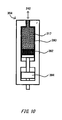
- Fig. 10 illustrates a cross-sectional view of the pump 304.
- the pump 304 has a cylinder 390, a piston 392, and an actuator 394.
- the pump 304 controls the filler content of the fluid 217 in the resilient portion 242 by: moving the piston 392 upward by the actuator 394; feeding the fluid 217 in the cylinder to the resilient portion 242; moving the piston 392 downward; and causing the fluid 217 to return from the resilient portion 242 into the cylinder 390.
- the muscular strength assisting instrument 202 can reduce the resilience of the resilient portion 242. Because of this, the muscular strength assisting instrument 202 can avoid giving the user 100 assisting force that obstructs an action of the user 100 to evade a dangerous situation.
- Fig. 13 is a schematic view of another muscular strength assisting instrument 204 worn by the user 100 as seen from a side.
- the configuration of members other than a shoe 330 is the same as that of the muscular strength assisting instrument 200 illustrated in Fig. 1 , and explanation of the same configuration is omitted.
- the shoe 330 detects the center of gravity of the user 100, and based on this, the detection unit 324 detects a dangerous posture of the user 100 as one example of a dangerous situation.
- Fig. 14 is a side view of the right shoe 330.
- the shoe 330 is worn on a foot of the user 100 in a manner similar to that for a normal shoe.
- the shoe 330 has a first load sensor 332, a second load sensor 334, and a cable 336.
- Fig. 16 is a schematic view of another muscular strength assisting instrument 206 worn by the user 100 as seen from the back.
- the upward, downward, leftward and rightward directions indicated with arrows in Fig. 16 are defined as the upward, downward, leftward and rightward directions of the muscular strength assisting instrument 206.
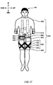
- Fig. 17 is a schematic view of the other muscular strength assisting instrument 206 worn by the user 100 as seen from the front.
- the upward, downward, leftward and rightward directions indicated with arrows in Fig. 17 are defined as the upward, downward, leftward and rightward directions of the muscular strength assisting instrument 206.
- the pants portion 402 is formed to cover the lower body of the user 100.
- the pants portion 402 may be short pants that cover halves of leg parts, or may be long pants that cover the leg parts entirely.
- the pants portion 402 is formed with elastic chemical fibers, etc..
- the pants portion 402 constricts the lower body of the user 100 with a certain degree of constraining force to contact closely thereto. Thereby, it becomes hard for the pants portion 402, when it is worn, to slip on the lower body of the user 100.
- the waist part actuator 410 has a first actuator 412 and a second actuator 414.
- the first actuator 412 is formed like a belt, and is provided on the right side of the user 100 and from a back part to a waist part.
- the first actuator 412 over its entire length, contacts the jacket portion 400 closely by being pasted to the jacket portion 400.
- the first actuator 412 includes a polymer material that extends and contracts when voltage is applied. When voltage is applied, the first actuator 412 extends or contracts in the longitudinal direction. The first actuator 412 extends or contracts to provide the assisting force to the user 100.
- the first actuator 412 is produced by winding a sheet member that is formed by sandwiching both surfaces of a planar polyrotaxane crosslinked body with elastic electrodes.
- the longitudinal direction of the first actuator 412 is parallel with the axial direction of the wound sheet member. Because the first actuator 412 is pliable, it is possible to reduce the sense of discomfort that is felt by the user when she/he walks with the first actuator 412 on.
- the first actuator 412 has a pair of outer electrodes, a mesh-like mesh electrode that is arranged between the pair of outer electrodes, and a non-ionic gel that is provided between the mesh electrode and each of the outer electrodes.
- a non-ionic gel is polyvinyl alcohol gel containing dimethylsulfoxide as a solvent.
- this first actuator 412 when voltage that is higher than voltage applied to the outer electrodes is applied to the mesh electrode, negative electric charges are introduced from the outer electrodes to the non-ionic gel, and the outer electrodes are attracted toward the mesh electrode. As a result, the distance between the pair of outer electrodes contracts.
- the distance of the pair of outer electrodes returns to the original state, and extends due to the elastic force of the non-ionic gel.
- the extension-contraction amount can be increased.
- the leg part actuator 420 has a third actuator 422, a fourth actuator 424, a fifth actuator 426, and a sixth actuator 428.
- the third actuator 422 is provided from the upper right to the lower left of the front surface of the pants portion 402 that covers a thigh part of the right leg.
- the third actuator 422 is formed like a belt.
- the wiring portion 404 applies voltage separately to a power source of the control box 500, the waist part actuator 410, and respective actuators of the leg part actuator 420 (hereinafter, referred to as the respective actuators).
- the control box 500 is provided on an upper portion on the front side of the pants portion 402.
- the control box 500 has a control apparatus 502, a power source unit 504, and an electric leakage sensor 506.
- the control apparatus 502 is in charge of the overall control of the muscular strength assisting instrument 206.
- the power source unit 504 applies voltage separately to the respective actuators through the wiring portion 404.
- the electric leakage sensor 506 detects electric leakage of the wiring portion 404 and the respective actuators.
- the action detection unit 508 is provided on a back part of the user 100, and detects an action of the upper body of the user 100.
- One example of the action detection unit 508 is a triaxial acceleration sensor. When the user 100 bends forward, the action detection unit 508 detects inclination of the upper body, and outputs inclination information about the upper body to the control apparatus 502.
- the power source switch 510 is provided at a central portion of a belly part of the user 100. By using the power source switch 510, the user 100 switches turning on and off of a main power source of the muscular strength assisting instrument 206.
- the control unit 518 Upon acquisition of a first power source signal from the power source switch 510, the control unit 518 turns on the main power source of the muscular strength assisting instrument 206. Upon acquisition of a next power source signal, the control unit 518 turns off the main power source of the muscular strength assisting instrument 206.
- the electric leakage sensor 506 detects, as one example of a dangerous situation, electric leakage at the wiring portion 404 and the respective actuators. In this case, when electric current that is higher than the electric current that is supposed to flow under control of the control unit 518 flows, the electric leakage sensor 506 judges that there has been electric leakage, and outputs, to the control unit 518, a notification indicating detection of electric leakage.
- the control unit 518 When the notification indicating that there has been electric leakage has been input from the electric leakage sensor 506, the control unit 518 forcibly turns off the main power source, and terminates supply of energy for extending or contracting the respective actuators. Thereby, when it is a dangerous situation due to electric leakage, the muscular strength assisting instrument 206 turns off the main power source, and the dangerous situation of the user 100 is avoided.
- the muscular strength assisting instrument 206 may apply voltage to the leg part actuator 420 and give the assisting force to obstruct raising of legs for a purpose of not allowing the user 100 to move forward.
- the muscular strength assisting instrument 206 can prevent the user 100 from falling into the large dent by not allowing the user 100 to move forward.
- the control unit 504 may cause the respective actuators to return to their natural length actively.
- a discharge circuit may be provided to an actuator to be driven electrically, such as the first actuator 412.
- the control unit 504 may cause the actuators to return to their natural length actively by discharging electrical charges accumulated in the actuators by means of the discharge circuit.
- the action detection unit 508 of the muscular strength assisting instrument 206 comprises an acceleration sensor
- the acceleration sensor outputs, to the control unit 504 via wiring, an acceleration signal about three directions from a waist part of the user.
- the action detection unit 508 acquires, from the acceleration sensor, an acceleration signal about three directions from a waist part of the user.
- the action detection unit 508 calculates acceleration based on the acquired acceleration signal, and creates a profile of acceleration changes in predetermined length of time. Note that one example of the predetermined length of time is two seconds.
- the detection unit judges that the user is falling down, and outputs, to the control apparatus 502, a state signal indicating that the user is not falling down.
- the control apparatus 502 Upon acquisition of the state signal, the control apparatus 502 performs voltage control processing.
- a pressure sensor may be provided as the detection unit to the waist or a buttocks part of the user, and detect that the user has sat down as a predetermined state.
- the detection unit acquires, from the pressure sensor, a signal about pressure applied to a waist part or a buttocks part of the user.
- the detection unit calculates pressure based on the acquired pressure signal, and when the calculated pressure exceeds a predetermined pressure threshold, judges that the user has sat down. Thereby, the detection unit detects that the user wearing the muscular strength assisting instrument 206 has sat down, and is not in a dangerous state.
- the detection unit When having detected that the user has sat down, the detection unit outputs, to the control apparatus 502, a state signal indicating that the user has sat down. Upon acquisition of the state signal, the control apparatus 502 performs muscular strength aid to the user without performing control that is to be performed when a dangerous situation has occurred.
- an image capturing apparatus may be used.
- the detection unit acquires an image of an area in front of the user that is captured by the image capturing apparatus.
- the detection unit may analyze the acquired image, and judge whether or not there is a step with predetermined height or higher in front of the user. Thereby, the detection unit detects presence of a step with predetermined height or higher in front of the user who is using the muscular strength assisting instrument 206.
- the detection unit judges that the user is going up stairs, and is not in a dangerous state, and outputs, to the control apparatus 502, a state signal indicating that the user is going up stairs.
- the control apparatus 502 Upon acquisition of the state signal, the control apparatus 502 performs voltage control processing.
- an angular sensor to measure the angle of the hip joint of the user may be provided.
- the detection unit acquires a bending angle signal of the hip joint of the user from the angular sensor.
- the detection unit for example calculates an angular change of the hip joint based on the angle signal, and acquires timing of bending and straightening of the legs of the user.
- the legs are bent at the hip joint and reach a stair, and then the hip joint is straightened to go up by the one stair; therefore, it may be detected that the user is going up stairs by comparing the timing of straightening of the hip joint and the timing of altitude changes of the user.
Landscapes
- Health & Medical Sciences (AREA)
- Public Health (AREA)
- General Health & Medical Sciences (AREA)
- Veterinary Medicine (AREA)
- Rehabilitation Therapy (AREA)
- Epidemiology (AREA)
- Pain & Pain Management (AREA)
- Animal Behavior & Ethology (AREA)
- Life Sciences & Earth Sciences (AREA)
- Physical Education & Sports Medicine (AREA)
- Biomedical Technology (AREA)
- Orthopedic Medicine & Surgery (AREA)
- Engineering & Computer Science (AREA)
- Neurology (AREA)
- Rehabilitation Tools (AREA)
- Manipulator (AREA)
Abstract
Description
- The present invention relates to a muscular strength assisting instrument.
- A muscular strength assisting instrument has been known, and such a muscular strength assisting instrument assists muscle of a user by means of a resilient member or the like (for example, please see Patent Literature 1).
[Patent Literature 1] Japanese Patent Application Publication No.2003-153928 - Such a muscular strength assisting instrument may give assisting force to prevent an action of a user who is trying to evade a dangerous situation when the user is in such a dangerous situation.
- A first aspect of the present invention provides a muscular strength assisting instrument comprising: an assisting unit that assists muscular strength of a user by using assisting force due to extension or contraction; a detection unit that detects a predetermined dangerous situation; and a control unit that adjusts the assisting force of the assisting unit when the dangerous situation is detected by the detection unit.
- The summary clause does not necessarily describe all necessary features of the embodiments of the present invention. The present invention may also be a subcombination of the features described above.
-
-
Fig. 1 is a rear schematic view of a muscular strength assisting instrument worn by a user. -
Fig. 2 is a side schematic view of a muscular strength assisting instrument worn by a user. -
Fig. 3 is a perspective view of a coupling instrument and an attachment instrument. -
Fig. 4 is a functional block diagram of a control box. -
Fig. 5 is a cross-sectional view of a release unit. -
Fig. 6 is a cross-sectional view of the release unit. -
Fig. 7 is a cross-sectional view of another unleashing unit. -
Fig. 8 is a cross-sectional view of another unleashing unit. -
Fig. 9 is a rear schematic view of another muscular strength assisting instrument worn by a user. -
Fig. 10 is a cross-sectional view of a pump. -
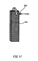
Fig. 11 is a schematic view of a resilient portion with a low filler content. -
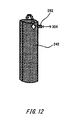
Fig. 12 is a schematic view of the resilient portion with a high filler content. -
Fig. 13 is a side schematic view of another muscular strength assisting instrument worn by a user. -
Fig. 14 is a side view of a shoe. -
Fig. 15 is a view illustrating an operation of a shoe. -
Fig. 16 is a rear schematic view of another muscular strength assisting instrument worn by a user. -
Fig. 17 is a front schematic view of another muscular strength assisting instrument worn by a user. -
Fig. 18 is a functional block diagram of the control box. -
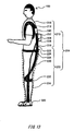
Fig. 19 is a view illustrating an operation of a muscular strength assisting instrument. - Hereinafter, (some) embodiment(s) of the present invention will be described. The embodiment(s) do(es) not limit the invention according to the claims, and all the combinations of the features described in the embodiment(s) are not necessarily essential to means provided by aspects of the invention.
-
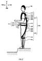
Fig. 1 is a schematic view of a muscularstrength assisting instrument 200 worn by auser 100 as seen from the back. The upward, downward, leftward and rightward directions indicated with arrows inFig. 1 are defined as the upward, downward, leftward and rightward directions of the muscularstrength assisting instrument 200.Fig. 2 is a schematic view of the muscularstrength assisting instrument 200 worn by the user as seen from a side. The upward, downward, forward and backward directions indicated with arrows inFig. 2 are defined as the upward, downward, forward and backward directions of the muscularstrength assisting instrument 200. - In
Fig. 1 andFig. 2 , the muscularstrength assisting instrument 200 comprises anupper attachment portion 210 and alower attachment portion 220. Theupper attachment portion 210 has upper assistingbelts 212, lower assistingbelts 252,coupling instruments 214, ajacket portion 218, acontrol box 300, ameasuring unit 310, andrelease units 340. Pairs of the upper assistingbelts 212, the lower assistingbelts 252, thecoupling instruments 214, and therelease units 340 are provided on the left and right. - The
lower attachment portion 220 hasattachment instruments 222,coupling belts 226, afixation belt 228,knee belts 230,heel belts 232, and apants portion 234. Pairs of theattachment instruments 222, thecoupling belts 226, theknee belts 230, and theheel belts 232 are provided on the left and right. - The right upper assisting
belt 212 is provided outside thejacket portion 218 and slidably at a part on the right shoulder. One end side of the right upper assistingbelt 212 is attached by being wrapped around a right shoulder part and an armpit part of theuser 100, and the right upper assistingbelt 212 is joined with itself at the shoulder part by a hook and pile fastener. The other end side of the right upper assistingbelt 212 is coupled to one end side of the right lower assistingbelt 252 by therelease unit 340. - The right lower assisting
belt 252 extends to a waist part on the back side of theuser 100. The other end side of the right lower assistingbelt 252 is provided with thecoupling instrument 214. The left upper assistingbelt 212 andlower assisting belt 252 also have similar configuration on the left side of theuser 100. Thecoupling instruments 214 are connected to a corresponding one of theattachment instruments 222 in thelower attachment portion 220 so that they can be attached to and detached from thecorresponding attachment instrument 222. - These upper assisting
belts 212 and lower assistingbelts 252 are formed by covering, with an elastic synthetic resin, elastic belt-like cloth into which natural or synthetic rubber fibers are woven. The upper assistingbelts 212 and the lower assistingbelts 252 assist muscular strength of a waist part of theuser 100 by using assisting force due to extension or contraction. The upper assistingbelts 212 and the lower assistingbelts 252 are one example of an assisting unit. - The
jacket portion 218 covers the upper body of theuser 100. Arm portions of thejacket portion 218 are not limited to a certain form, and may be short sleeves, long sleeves, sleeveless, etc.. A material of thejacket portion 218 is not particularly limited, and for example, textiles, webs, or the like are used. - The
fixation belt 228 is attached by being wrapped on a lower side part of a waist part of theuser 100. The two left andright coupling belts 226 are connected to upper parts of thefixation belt 228. Furthermore, the two left and right pairs of theknee belts 230 are connected to lower parts of thefixation belt 228. - Upper edges of the
coupling belts 226 are each provided with theattachment instrument 222. Theright attachment instrument 222 is connected with theright coupling instrument 214 of theupper attachment portion 210 so that it can be attached thereto and detached therefrom, and fixes the right lower assistingbelt 252 to thefixation belt 228. Theleft attachment instrument 222 has similar configuration. - The
measuring unit 310 is attached to thefixation belt 228, and is arranged so that it is at the center of a belly part of theuser 100. Themeasuring unit 310 has aultrasonic sensor 312, anangular adjustment section 314, and acable 316. - The
ultrasonic sensor 312 has a transmitter that transmits ultrasonic waves, and a receiver that receives sound waves reflected on the ground. Theultrasonic sensor 312 measures the length of time from transmission of ultrasonic waves by the transmitter to acquisition of reflected waves by the receiver. Theultrasonic sensor 312 outputs the measured length of time to thecontrol box 300 through thecable 316. - The
angular adjustment section 314 is configured with two members that can pivot relatively on an axis extending leftward and rightward. Theultrasonic sensor 312 is attached to one of the members, and thefixation belt 228 is attached to the other member. By causing theangular adjustment section 314 to pivot, the direction to which ultrasonic waves of theultrasonic sensor 312 are transmitted can be changed according to theuser 100. Thereby, for example, the muscularstrength assisting instrument 200 can direct the oscillation of ultrasonic waves toward an area ahead the tiptoes of theuser 100 according to the step or height of theuser 100. - The
control box 300 is electrically connected with the left andright release units 340 by thecable 260, and is retained by the left andright release units 340. Thereby, thecontrol box 300 is arranged at the center on a back part of theuser 100. Thecontrol box 300 judges whether or not theuser 100 is in a dangerous situation. When thecontrol box 300 judges that theuser 100 is in a dangerous situation, therelease unit 340 releases the resilience being generated by the upper assistingbelts 212 and the lower assistingbelts 252. To release the resilience is one example of adjustment of the assisting force by thecontrol box 300. - The
right knee belt 230 has two belts. These two belts intersect at a part that is below the front side of a knee after passing through left and right parts of a waist part, a buttock part, and a thigh part of the right leg of theuser 100, and attached by being joined with each other at a part that is below the back side of the knee by a hook and pile fastener. Both the edges of theright heel belt 232 are connected to left and right parts of a knee part of theright knee belt 230. Theheel belt 232 is attached from the left and right side surfaces of a lower thigh part at which theheel belt 232 is attached to theknee belt 230, to a heel part. Theleft knee belt 230 andheel belt 232 have similar configuration on the left leg side of theuser 100. - The
knee belts 230 and theheel belts 232 are non-elastic, and formed by covering, with a synthetic resin or the like, non-elastic, belt-like cloth into which natural or synthetic fibers are woven. A synthetic resin sheet or leather may be used as theknee belts 230 and theheel belts 232. - The
pants portion 234 covers both the legs of theuser 100 down to parts around the ankles. A material of thepants portion 234 is not particularly limited, and for example, textiles, webs, or the like are used. Thefixation belt 228 is wrapped outside an upper part of thepants portion 234, and theknee belts 230 and theheel belts 232 are sewed inside thepants portion 234. Thereby, upward movement of thefixation belt 228 is restricted by theknee belts 230 and theheel belts 232. -
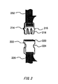
Fig. 3 is a perspective view of thecoupling instrument 214 and theattachment instrument 222. Thecoupling instrument 214 has: two engagingprojections 215 that each have an inclined surface on one side; and tworesilient claws 216. Theattachment instrument 222 has afitting portion 223 and engagingholes 224. When thecoupling instrument 214 is inserted to thefitting portion 223, the engagingprojections 215 are deformed inward due to the resilience of theresilient claws 216 and the inclined surfaces of the engagingprojections 215. When thecoupling instrument 214 is further inserted to thefitting portion 223 in the state, the engagingprojections 215 engage with the engagingholes 224 due to fitting of the engagingprojections 215 and the engagingholes 224, and thecoupling instrument 214 and theattachment instrument 222 are connected. - In contrast, the connection between the
coupling instrument 214 and theattachment instrument 222 can be released by bending the engagingprojections 215 inward through the engagingholes 224 of theattachment instrument 222. If they are separated in this state, the connection between thecoupling instrument 214 and theattachment instrument 222 can be released. -
Fig. 4 illustrates a functional block diagram of thecontrol box 300. Thecontrol box 300 has adetection unit 324 and acontrol unit 326. - The
detection unit 324 detects whether or not theuser 100 is in a predetermined dangerous situation based on distance. In the present embodiment, thedetection unit 324 detects, as one example of a dangerous situation, whether or not there is a step with predetermined height or higher in an area onto which theuser 100 steps. - In this case, the
detection unit 324 acquires the length of time output by the measuringunit 310, and calculates the distance by multiplying the length of time by the speed of sound. When the calculated distance is equal to or longer than predetermined distance, or equal to or shorter than predetermined distance, thedetection unit 324 judges that there is a step with predetermined height or higher. Thedetection unit 324 may detect that the muscularstrength assisting instrument 200 is worn by theuser 100, calculate the above-mentioned distance, stores the calculated distance as the reference distance, and compare distance calculated thereafter with the reference distance, and when their difference exceeds a predetermined value, may judge that there is a step with predetermined height or higher. - When having detected that there is the above-mentioned step, the
detection unit 324 outputs a release signal to thecontrol unit 326. In contrast, when having not detected that there is the above-mentioned step, thedetection unit 324 does not output a release signal. When having acquired the release signal from thedetection unit 324, thecontrol unit 326 outputs a drive signal for driving therelease unit 340 to therelease unit 340. -
Fig. 5 andFig. 6 are cross-sectional views of therelease unit 340.Fig. 5 illustrates a state where the upper assistingbelt 212 and the lower assistingbelt 252 are coupled by therelease unit 340. In contrast,Fig. 6 illustrates a state where the upper assistingbelt 212 and the lower assistingbelt 252 are uncoupled by therelease unit 340. - The
release unit 340 has anengaging claw 342, anengaging plate 344, asupport unit 346, a biasingmember 348, arod 350, ahousing 352, and adrive unit 354. Thehousing 352 is a hollow rectangular parallelepiped having a rectangular opening on its one surface. Thesupport unit 346 and the biasingmember 348 are provided inside thehousing 352. Thedrive unit 354 and the upper assistingbelt 212 are fixed to the outer surface of thehousing 352. - The lower assisting
belt 252 is fixed to one end side of the engagingclaw 342. Two saw blade-like claws are provided to the other end side of the engagingclaw 342. - A central portion of the
engaging plate 344 is supported pivotably by thesupport unit 346. One end of theengaging plate 344 is biased downward as seen in the figure by the biasingmember 348. Also, the other end of theengaging plate 344 abuts on therod 350. - The
rod 350 penetrates thehousing 352. One end side of therod 350 is connected to thedrive unit 354, and the other end side abuts on theengaging plate 344. - In the state as illustrated in
Fig. 5 , a drive signal has not been input to thedrive unit 354, and therod 350 is withdrawn toward to thedrive unit 354. Because the biasing force of the biasingmember 348 is in action in this state, the engagingplate 344 pivots counterclockwise as seen in the figure, and the above-mentioned one end of theengaging plate 344 is positioned at a lower part as seen in the figure. - Accordingly, the engaging
plate 344 engages with the engagingclaw 342, and restricts movement of the engagingclaw 342. Thereby, the upper assistingbelt 212 and the lower assistingbelt 252 are coupled, and the transmission path of assisting force of the upper assistingbelt 212 and the lower assistingbelt 252 is established. - In
Fig. 6 , due to a drive signal from thecontrol unit 326 being input to thedrive unit 354, thedrive unit 354 is pushing therod 350 downward. Thereby, therod 350 pushes down the above-mentioned other end of theengaging plate 344 against the biasing force of the biasingmember 348. - Accordingly, the engaging
plate 344 pivots clockwise as seen in the figure, the above-mentioned one end of theengaging plate 344 is lifted, and engagement between theengaging plate 344 and the engagingclaw 342 is released. Thereby, the upper assistingbelt 212 and the lower assistingbelt 252 are physically uncoupled, and the transmission path of the assisting force is physically blocked. In this manner, the assisting force for theuser 100 is unleashed. - The muscular
strength assisting instrument 200 shown in the present embodiment unleashes the assisting force of the muscularstrength assisting instrument 200 when a dangerous situation of theuser 100 is detected by thedetection unit 324. Thereby, the muscularstrength assisting instrument 200 can prevent an action of theuser 100 to evade a dangerous situation from being obstructed. - In the above-mentioned embodiment, the
detection unit 324 detects a step with predetermined height or higher as a dangerous situation. That is, thedetection unit 324 judges that it is a dangerous situation in both a case that a step is an upward step relative to the current position of theuser 100 and a case that a step is a downward step relative to the current position of theuser 100. Instead of this, thedetection unit 324 may judge that it is a dangerous situation in either of the cases, in particular when a step is a downward step relative to the current position of theuser 100, and may not judge that it is a dangerous situation when a step is an upward step relative to the current position of theuser 100. When the ground onto which theuser 100 is about to step is low, and theuser 100 does step onto the ground, it is more likely for theuser 100 to lose the balance of his/her body. In this case, unnecessary assisting force is not given to theuser 100, and falling can be prevented. In contrast, when the ground onto which theuser 100 steps is high, the assisting force is given to theuser 100, and a load on the muscle is reduced. - Also, the
detection unit 324 may detect that it is a dangerous situation when a prerecorded safety condition is not met. A safety condition is prerecorded in thedetection unit 324, and thedetection unit 324 detects whether the prerecorded safety condition is not fulfilled. When thedetection unit 324 judges that a detected result does not fulfill the safety condition, thedetection unit 324 judges that theuser 100 is in a dangerous situation. - Note that in the above-mentioned embodiment, the
coupling instrument 214 and theattachment instrument 222, and therelease unit 340 are provided separately. Instead of this, therelease unit 340 may perform both coupling and uncoupling of the upper assistingbelt 212 and the lower assistingbelt 252 in wearing and removal of the muscularstrength assisting instrument 200. -
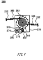
Fig. 7 andFig. 8 are cross-sectional views of another unleashingunit 360.Fig. 7 illustrates a state where the assisting force of the upper assistingbelt 212 and the lower assistingbelt 252 is in action. In contrast,Fig. 8 illustrates a state where the assisting force of the upper assistingbelt 212 and the lower assistingbelt 252 is unleashed. The unleashingunit 360 has arotary body 362, engagingprojections 364,adjustment belts claw 370, a biasingmember 372, arod 374, asupport unit 376, ahousing 378, and adrive unit 380. - The
rotary body 362 is retained by a rotation axis so that it is rotatable. The saw blade-likeengaging projections 364 are provided to the outer circumference of therotary body 362. - A central portion of the engaging
claw 370 is supported by thesupport unit 376 so that it is pivotable. One end of the engagingclaw 370 is provided with a projection to engage with the engagingprojections 364 of therotary body 362. The one end of the engagingclaw 370 is biased by the biasingmember 372 upward from below as seen in the figure. The other end of the engagingclaw 370 abuts on therod 374. - The
adjustment belts adjustment belt 366 is fixed to the rotation axis. The other end of theadjustment belt 366 is connected to the lower assistingbelt 252. - One end of the
adjustment belt 368 is fixed to a central portion of therotary body 362, and the fixed portion rotates integrally with therotary body 362. Furthermore, theadjustment belt 368 is wrapped around the fixed portion. The other end of theadjustment belt 368 is connected to the upper assistingbelt 212. - In the state as illustrated in
Fig. 7 , a drive signal has not been input to thedrive unit 380, and therod 374 is withdrawn toward to thedrive unit 380. Because the biasing force of the biasingmember 372 is in action in this state, the engagingclaw 370 pivots counterclockwise as seen in the figure, and the above-mentioned one end of the engagingclaw 370 is positioned at an upper part as seen in the figure. - Accordingly, the projection of the engaging
claw 370 engages with any one of the engagingprojections 364 to restrict rotation of therotary body 362. Thereby, extension of the upper assistingbelt 212 is restricted, and the assisting force of the upper assistingbelt 212 and the lower assistingbelt 252 are acting on theuser 100. - In
Fig. 8 , due to a drive signal from thecontrol unit 326 being input to thedrive unit 380, thedrive unit 380 is pushing therod 374 upward. Thereby, therod 374 pushes up the above-mentioned other end of the engagingclaw 370 against the biasing force of the biasingmember 372. - Accordingly, the engaging
claw 370 pivots clockwise as seen in the figure, the above-mentioned one end of the engagingclaw 370 is pulled downward, and engagement between the engagingclaw 370 and the engagingprojections 364 is released. Thereby, it becomes possible for therotary body 362 to rotate counterclockwise, and theadjustment belt 368 wrapped around therotary body 362 is pulled out by the resilience of the upper assistingbelt 212 and the lower assistingbelt 252. Due to theadjustment belt 368 being pulled out, there is no longer tension strength of the upper assistingbelt 212 and the lower assistingbelt 252, and the assisting force for theuser 100 is unleashed. Thereby, the muscularstrength assisting instrument 200 can prevent an action of theuser 100 to evade a dangerous situation from being obstructed. -
Fig. 9 is a schematic view of another muscularstrength assisting instrument 202 worn by theuser 100 as seen from the back. The upward, downward, leftward and rightward directions indicated with arrows inFig. 9 are defined as the upward, downward, leftward and rightward directions of the muscularstrength assisting instrument 202. In the muscularstrength assisting instrument 202 illustrated inFig. 9 , the configuration of members other than assistingbelts 213,resilient portions 242, acontrol box 302, and apump 304 is the same as that of the muscularstrength assisting instrument 200 illustrated inFig. 1 , and explanation of the same configuration is omitted. - The assisting
belts 213 are non-elastic. One end of the assistingbelt 213 on the back side is connected to a corresponding one of theresilient portions 242. - The
resilient portions 242 are arranged on left and right parts of a back part of theuser 100. One end of theresilient portion 242 is connected to a corresponding one of the upper assistingbelts 212, and the other end is fixed to a corresponding one of theattachment instruments 222 via thecoupling instrument 214. - The
resilient portions 242 are coupled with thepump 304 via acoupling tube 262. Thepump 304 is retained at the center of the back of theuser 100 by thecoupling tube 262. - When a dangerous situation of the
user 100 has been detected, thecontrol box 302 outputs a drive signal for driving thepump 304. In contrast, when a dangerous situation of theuser 100 is not detected, thecontrol box 302 does not output a drive signal for driving thepump 304. - The
resilient portion 242 is formed with a resilient material, and its cross-sectional shape is rectangular and hollow. The inside of theresilient portion 242 is filled withfluid 217. -
Fig. 10 illustrates a cross-sectional view of thepump 304. Thepump 304 has acylinder 390, apiston 392, and anactuator 394. Thepump 304 controls the filler content of the fluid 217 in theresilient portion 242 by: moving thepiston 392 upward by theactuator 394; feeding the fluid 217 in the cylinder to theresilient portion 242; moving thepiston 392 downward; and causing the fluid 217 to return from theresilient portion 242 into thecylinder 390. -
Fig. 11 illustrates a state where the filler content of the fluid 217 in theresilient portion 242 is low, andFig. 12 illustrates a state where the filler content of the fluid 217 in theresilient portion 242 is high. InFig. 11 , because the filler content of the fluid 217 in theresilient portion 242 is low, the cross-sectional shape of theresilient portion 242 remains rectangular, and the flexural rigidity is low. In contrast, inFig. 12 , because the filler content of the fluid 217 in theresilient portion 242 is high, the cross-sectional shape of theresilient portion 242 is deformed to become elliptical, and the flexural rigidity is high. Thereby, the higher the amount of the fluid 217 filling theresilient portion 242, the higher the assisting force for theuser 100. Note that any of gas and liquid, or a mixture of them can be used as thefluid 217. - Upon acquisition of a drive signal from the
control unit 326, thepump 304 drives theactuator 394 to move thepiston 392 downward. By moving thepiston 392 downward, the fluid 217 is caused to return from theresilient portion 242 into thecylinder 390. By reducing the filler content of the fluid 217 in theresilient portion 242, the resilience of theresilient portion 242 can be reduced. - In this manner, when the
detection unit 324 has detected a dangerous situation of theuser 100, the muscularstrength assisting instrument 202 can reduce the resilience of theresilient portion 242. Because of this, the muscularstrength assisting instrument 202 can avoid giving theuser 100 assisting force that obstructs an action of theuser 100 to evade a dangerous situation. - Although an example in which the
measuring unit 310 in the present embodiment uses theultrasonic sensor 312 has been shown, laser reflection may be used. Furthermore, instead of them, an image of an area onto which theuser 100 steps may be captured by using a camera, the image in front of theuser 100 may be analyzed, and it may be detected whether or not there is a step in the area onto which theuser 100 steps. -
Fig. 13 is a schematic view of another muscularstrength assisting instrument 204 worn by theuser 100 as seen from a side. In the muscularstrength assisting instrument 204 illustrated inFig. 13 , the configuration of members other than ashoe 330 is the same as that of the muscularstrength assisting instrument 200 illustrated inFig. 1 , and explanation of the same configuration is omitted. Theshoe 330 detects the center of gravity of theuser 100, and based on this, thedetection unit 324 detects a dangerous posture of theuser 100 as one example of a dangerous situation. -
Fig. 14 is a side view of theright shoe 330. Theshoe 330 is worn on a foot of theuser 100 in a manner similar to that for a normal shoe. Theshoe 330 has afirst load sensor 332, asecond load sensor 334, and acable 336. - The
first load sensor 332 is provided to theshoe 330 on the tiptoe side on the back side of the foot, and detects a load on the tiptoe side of theuser 100. Thesecond load sensor 334 is provided to theshoe 330 on the heel side of the backside of the foot, and detects a load on the heel side of theuser 100. Load detection values of both the load sensors are output to thecontrol box 306 through thecable 336. A left shoe has the same configuration. -
Fig. 15 illustrates a state where the body weight of theuser 100 is applied onto the heel side. When the body weight is applied onto the heel side of both the feet as illustrated inFig. 15 , it is inferred that theuser 100 is bending backward. If theuser 100 bends forward in this posture, the muscularstrength assisting instrument 204 gives theuser 100 force to return from the forward-bent posture, so theuser 100 may fall backward. Accordingly, in the backward-bent posture of theuser 100, the muscularstrength assisting instrument 204 desirably does not give theuser 100 the assisting force of the upper assistingbelt 212 and the lower assistingbelt 252. - The
detection unit 324 acquires load detection values of thefirst load sensor 332 and thesecond load sensor 334 from both the left andright shoes 330. When, for both the left andright shoes 330, a ratio of a load indicated by thesecond load sensor 334 relative to a load indicated by thefirst load sensor 332 becomes larger than a predetermined ratio, thedetection unit 324 judges that the center of gravity of the body weight of theuser 100 has moved backward. - When having judged that the center of gravity of the body weight of the
user 100 has moved backward, thedetection unit 324 outputs a release signal to thecontrol unit 326. When having not judged that the center of gravity pf the body weight of theuser 100 has moved backward, thedetection unit 324 does not output a release signal to thecontrol unit 326. Upon acquisition of a release signal from thedetection unit 324, thecontrol unit 326 outputs a drive signal for driving therelease unit 340. Then, therelease unit 340 that has acquired the drive signal releases engagement of the engagingclaw 342 to unleash the assisting force of the upper assistingbelt 212 and the lower assistingbelt 252. - The muscular
strength assisting instrument 204 may comprise a triaxial acceleration sensor in thecontrol box 302, in addition to two load sensors of theshoe 330. When comprising the triaxial acceleration sensor, the muscularstrength assisting instrument 204 can detect, in detail, a dangerous situation that is related to a posture of theuser 100 because a posture of a waist part of theuser 100 relative to the gravitational direction can also be detected. Instead of or in addition to the acceleration sensor, the muscularstrength assisting instrument 206 may use a muscle potential sensor to detect a dangerous situation of theuser 100. Because when theuser 100 falls down, a part of the body of theuser 100 stiffens instantly, the muscle potential sensor may judge that theuser 100 is in a dangerous situation when the stiffening force has exceeded a predetermined threshold. -
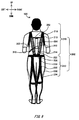
Fig. 16 is a schematic view of another muscularstrength assisting instrument 206 worn by theuser 100 as seen from the back. The upward, downward, leftward and rightward directions indicated with arrows inFig. 16 are defined as the upward, downward, leftward and rightward directions of the muscularstrength assisting instrument 206.Fig. 17 is a schematic view of the other muscularstrength assisting instrument 206 worn by theuser 100 as seen from the front. The upward, downward, leftward and rightward directions indicated with arrows inFig. 17 are defined as the upward, downward, leftward and rightward directions of the muscularstrength assisting instrument 206. - The muscular
strength assisting instrument 206 is worn on the upper body and the lower body of theuser 100, and assists the muscular strength of a waist part of theuser 100. The muscularstrength assisting instrument 206 has: ajacket portion 400 and apants portion 402; awiring portion 404; awaist part actuator 410, aleg part actuator 420; acontrol box 500; anaction detection unit 508; and apower source switch 510. - The
jacket portion 400 is formed to cover the upper body of theuser 100. Arm portions of thejacket portion 400 are not limited to a certain form, and may be short sleeves, long sleeves, sleeveless, etc.. Thejacket portion 400 is formed with elastic chemical fibers, etc. Thejacket portion 400 constricts the upper body of theuser 100 with a certain degree of constraining force to contact closely thereto. Thereby, it becomes hard for thejacket portion 400, when it is worn, to slip on the upper body of theuser 100. - The
pants portion 402 is formed to cover the lower body of theuser 100. Thepants portion 402 may be short pants that cover halves of leg parts, or may be long pants that cover the leg parts entirely. Thepants portion 402 is formed with elastic chemical fibers, etc.. Thepants portion 402 constricts the lower body of theuser 100 with a certain degree of constraining force to contact closely thereto. Thereby, it becomes hard for thepants portion 402, when it is worn, to slip on the lower body of theuser 100. - The
waist part actuator 410 has afirst actuator 412 and asecond actuator 414. Thefirst actuator 412 is formed like a belt, and is provided on the right side of theuser 100 and from a back part to a waist part. Thefirst actuator 412, over its entire length, contacts thejacket portion 400 closely by being pasted to thejacket portion 400. - The
first actuator 412 includes a polymer material that extends and contracts when voltage is applied. When voltage is applied, thefirst actuator 412 extends or contracts in the longitudinal direction. Thefirst actuator 412 extends or contracts to provide the assisting force to theuser 100. - One example of a polymer material is a polyrotaxane crosslinked body. The
first actuator 412 is produced by winding a sheet member that is formed by sandwiching both surfaces of a planar polyrotaxane crosslinked body with elastic electrodes. Here, the longitudinal direction of thefirst actuator 412 is parallel with the axial direction of the wound sheet member. Because thefirst actuator 412 is pliable, it is possible to reduce the sense of discomfort that is felt by the user when she/he walks with thefirst actuator 412 on. - Another example of a polymer material is a non-ionic gel. In this case, the
first actuator 412 has a pair of outer electrodes, a mesh-like mesh electrode that is arranged between the pair of outer electrodes, and a non-ionic gel that is provided between the mesh electrode and each of the outer electrodes. One example of a non-ionic gel is polyvinyl alcohol gel containing dimethylsulfoxide as a solvent. In thisfirst actuator 412, when voltage that is higher than voltage applied to the outer electrodes is applied to the mesh electrode, negative electric charges are introduced from the outer electrodes to the non-ionic gel, and the outer electrodes are attracted toward the mesh electrode. As a result, the distance between the pair of outer electrodes contracts. Conversely, when voltage application is terminated, the distance of the pair of outer electrodes returns to the original state, and extends due to the elastic force of the non-ionic gel. By laminating a plurality of the combination of the outer electrodes, the mesh electrode, and the non-ionic gel, the extension-contraction amount can be increased. - Another example of a polymer material is a polypyrrole film. A polypyrrole film immersed in an electrolyte expands or contracts when voltage is applied. For example, when positive voltage is applied, a polypyrrole film expands. When negative voltage is applied, a polypyrrole film contracts. Because the
first actuator 412, when containing a polypyrrole film, requires an electrolyte, thefirst actuator 412 needs to be sealed. - The
second actuator 414 is provided on the left side of the user and from a back part to a waist part. Because the other configuration of thesecond actuator 414 is similar to that of the first actuator, explanation of the similar configuration is omitted. - The
leg part actuator 420 has athird actuator 422, afourth actuator 424, afifth actuator 426, and asixth actuator 428. Thethird actuator 422 is provided from the upper right to the lower left of the front surface of thepants portion 402 that covers a thigh part of the right leg. Thethird actuator 422 is formed like a belt. Thethird actuator 422, over its entire length, contacts thepants portion 402 closely by being pasted to thepants portion 402. - The
third actuator 422 includes a polymer material that extends and contracts when voltage is applied, and when voltage is applied, extends or contracts in the longitudinal direction. Thethird actuator 422 extends and contracts to assist raising and lowering of the right leg of theuser 100 at a time of walking. Because the other configuration of the third actuator is similar to that of thefirst actuator 412, explanation of the similar configuration is omitted. - The
fourth actuator 424 is provided from the upper left to the lower right of the front surface of thepants portion 402 that covers the thigh part of the right leg. Accordingly, thethird actuator 422 and thefourth actuator 424 intersect on the front surface of a thigh part of the right leg. Thefifth actuator 426 is provided from the upper left to the lower right of the front surface of thepants portion 402 that covers a thigh part of the left leg. Thesixth actuator 428 is provided from the upper right to the lower left of the front surface of thepants portion 402 that covers the thigh part of the left leg. Thefifth actuator 426 and thesixth actuator 428 intersect on the front surface of a thigh part of the right leg. The other configuration of thefourth actuator 424, thefifth actuator 426, and thesixth actuator 428 is similar to that of thethird actuator 422, and explanation of the similar configuration is omitted. - The
wiring portion 404 applies voltage separately to a power source of thecontrol box 500, thewaist part actuator 410, and respective actuators of the leg part actuator 420 (hereinafter, referred to as the respective actuators). Thecontrol box 500 is provided on an upper portion on the front side of thepants portion 402. Thecontrol box 500 has acontrol apparatus 502, apower source unit 504, and anelectric leakage sensor 506. - The
control apparatus 502 is in charge of the overall control of the muscularstrength assisting instrument 206. Thepower source unit 504 applies voltage separately to the respective actuators through thewiring portion 404. Theelectric leakage sensor 506 detects electric leakage of thewiring portion 404 and the respective actuators. - The
action detection unit 508 is provided on a back part of theuser 100, and detects an action of the upper body of theuser 100. One example of theaction detection unit 508 is a triaxial acceleration sensor. When theuser 100 bends forward, theaction detection unit 508 detects inclination of the upper body, and outputs inclination information about the upper body to thecontrol apparatus 502. - The
power source switch 510 is provided at a central portion of a belly part of theuser 100. By using thepower source switch 510, theuser 100 switches turning on and off of a main power source of the muscularstrength assisting instrument 206. -
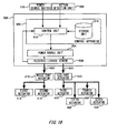
Fig. 18 is a functional block for explaining control of thecontrol box 500. As illustrated inFig. 18 , thecontrol apparatus 502 has acontrol unit 518 and astorage unit 514. - The
control unit 518 acquires the inclination information from theaction detection unit 508. Furthermore, thecontrol unit 518 acquires a power source signal from thepower source switch 510. By referring to thestorage unit 514 based on the acquired inclination information, thecontrol unit 518 controls thepower source unit 504 based on the relationship between the inclination information stored in thestorage unit 514 and power source control, and assists the muscular strength by applying voltage separately to the respective actuators. -
Fig. 19 is a view illustrating an operation of the muscularstrength assisting instrument 206. As illustrated inFig. 19 , when voltage is applied to thesecond actuator 414, thesecond actuator 414 contracts. Due to the contraction of thesecond actuator 414, the assisting force for raising the upper body is given to theuser 100. - Upon acquisition of a first power source signal from the
power source switch 510, thecontrol unit 518 turns on the main power source of the muscularstrength assisting instrument 206. Upon acquisition of a next power source signal, thecontrol unit 518 turns off the main power source of the muscularstrength assisting instrument 206. - The
electric leakage sensor 506 detects, as one example of a dangerous situation, electric leakage at thewiring portion 404 and the respective actuators. In this case, when electric current that is higher than the electric current that is supposed to flow under control of thecontrol unit 518 flows, theelectric leakage sensor 506 judges that there has been electric leakage, and outputs, to thecontrol unit 518, a notification indicating detection of electric leakage. - When the notification indicating that there has been electric leakage has been input from the
electric leakage sensor 506, thecontrol unit 518 forcibly turns off the main power source, and terminates supply of energy for extending or contracting the respective actuators. Thereby, when it is a dangerous situation due to electric leakage, the muscularstrength assisting instrument 206 turns off the main power source, and the dangerous situation of theuser 100 is avoided. - Instead of or in addition to this, also in the muscular
strength assisting instrument 206 provided with the respective actuators, a dangerous situation of theuser 100 may be detected by using themeasuring unit 310 shown inFig. 1 or theshoe 330 shown inFig. 14 , and thecontrol unit 518 may turn off the main power source. Also, when a dangerous situation of theuser 100 is detected, the muscularstrength assisting instrument 206 may give theuser 100 the assisting force from the respective actuators for avoiding the dangerous situation. To give the assisting force for avoiding a dangerous situation is one example of adjustment of the assisting force by thecontrol unit 518. - When a large dented step is detected in a forward area, the muscular
strength assisting instrument 206 may apply voltage to theleg part actuator 420 and give the assisting force to obstruct raising of legs for a purpose of not allowing theuser 100 to move forward. The muscularstrength assisting instrument 206 can prevent theuser 100 from falling into the large dent by not allowing theuser 100 to move forward. - In another example, when it is detected that the
user 100 stumbles on a downward slope, the muscularstrength assisting instrument 206 may apply voltage to theleg part actuator 420 and thewaist part actuator 410, give theuser 100 the assisting force to cause legs to stretch out further forward and the assisting force for raising the upper body, and give the assisting force to prevent falling. Furthermore, by providing, to the muscularstrength assisting instrument 206, an actuator to assist muscular strength of an arm portion, the muscularstrength assisting instrument 206 may give the arm portion of theuser 100 force to assist an action to keep balance for preventing falling. In this manner, the muscularstrength assisting instrument 206 can avoid a dangerous situation of theuser 100 by adjusting the assisting force for theuser 100. - Also, instead of or in addition to turning off the main power source, by providing the
release unit 340 shown inFig. 5 to one end of each of the respective actuators, the respective actuators may be uncoupled from thejacket portion 400 by driving therelease unit 340 when a dangerous situation of theuser 100 is detected. Although in the examples illustrated inFig. 16 andFig. 17 , a dangerous situation of theuser 100 is detected by theaction detection unit 508, instead of or in addition to this, the muscularstrength assisting instrument 206 may detect a dangerous situation of theuser 100 by using a muscle potential sensor. Because when theuser 100 falls down, a part of the body of theuser 100 stiffens instantly, the muscle potential sensor may judge that theuser 100 is in a dangerous situation when the stiffening force exceeds a predetermined threshold. - In a dangerous situation, instead of or in addition to turning off the main power source, the
control unit 504 may cause the respective actuators to return to their natural length actively. In this case, a discharge circuit may be provided to an actuator to be driven electrically, such as thefirst actuator 412. In a dangerous situation, in addition to termination of power supply from thepower source unit 504 to the actuators, thecontrol unit 504 may cause the actuators to return to their natural length actively by discharging electrical charges accumulated in the actuators by means of the discharge circuit. Thereby, when the actuators are caused to return to their natural length rapidly and the user avoids a danger, it becomes possible to surely prevent the actuators from obstructing an action of the user. - A dielectric elastomer actuator formed by gluing elastic sheet-like electrodes onto both the surfaces of an elastomer film such as silicone and acryl may be used as the
first actuator 412 and the like. The actuator extends in the planar direction by sandwiching and squashing the elastomer film with the Coulomb's force generated by voltage application to the electrodes. In a dangerous situation, in addition to controlling voltage to the actuator, thecontrol unit 504 may physically block the transmission path for the assisting force of the actuator by using therelease unit 340 shown inFig. 5 to Fig. 8 . - The
first actuator 412 and the like are preferably deformable due to external force at least when power is not being supplied. In this case, the rigidity or resilience at a time of non-supply of power is preferably lower than those at a time of supply. Thereby, because thefirst actuator 412 is easily deformed due to force received from the user when power supply is terminated in a dangerous situation, obstruction of an action of the user is prevented. When an actuator is a rotary motor, an oil hydraulic cylinder, or the like, a mechanism to free an action of the actuator, such as a clutch mechanism or an oil removing mechanism, in a dangerous situation is provided, but such a mechanism needs not be provided in a case of the above-mentioned actuator. Furthermore, due to the pliability of an actuator itself, the actuator can serve as a buffer material in a case of falling or the like. - Furthermore, as another example of a dangerous situation, the assisting force of the muscular
strength assisting instrument 200 and the like may be unleashed or reduced upon detection of pouring of water over theuser 100. Note that pouring of water over the muscularstrength assisting instrument 206 can be detected by detecting an electric current value, detecting an electric leakage amount, or detecting humidity around the respective actuators by a hygrometer. Thereby, when theuser 100 falls into water or in other cases, an electric shock of theuser 100 due to electric leakage of electric equipment such as an actuator can be prevented. Also, an electric leakage breaker may be provided to thecontrol box 500, and power supply to the respective actuators may be blocked when electric leakage has occurred. - Among the
detection unit 324 and thecontrol units control units - Also, when the
action detection unit 508 of the muscularstrength assisting instrument 206 comprises an acceleration sensor, the acceleration sensor outputs, to thecontrol unit 504 via wiring, an acceleration signal about three directions from a waist part of the user. - When it has been detected that output from the acceleration sensor corresponds to a state where the user is falling down, a state signal indicating that the user is falling down is output to the
control unit 504. Upon acquisition of the state signal, thecontrol apparatus 502 controls thepower source unit 504 to discontinue aid to walking by actuators such as thefirst actuator 412 and thesecond actuator 414. That is, a free state where there is no aid of the muscularstrength assisting instrument 206 to the user is provided. Note that instead of discontinuation of aid to walking, thecontrol apparatus 504 may lower output of the respective actuators by lowering applied voltage, thereby restricting the aid to walking. - The
action detection unit 508 acquires, from the acceleration sensor, an acceleration signal about three directions from a waist part of the user. Theaction detection unit 508 calculates acceleration based on the acquired acceleration signal, and creates a profile of acceleration changes in predetermined length of time. Note that one example of the predetermined length of time is two seconds. - It has been known that when a human falls down, a characteristic acceleration change is observed at his/her waist part. Accordingly, as a reference profile, a profile of acceleration changes measured when the user intentionally falls down is stored in advance in the
storage unit 514. Theaction detection unit 508 detects that the user who is using the muscularstrength assisting instrument 206 is falling down by comparing the reference profile stored in thestorage unit 514 and a profile calculated based on output from the acceleration sensor. - When the created profile and the reference profile match about a predetermined condition, the detection unit such as the
detection unit 324 that detects a dangerous situation judges that the user is falling down, and outputs, to thecontrol apparatus 502, a state signal indicating that the user is falling down. Upon acquisition of the state signal, thecontrol apparatus 502 terminates voltage control processing. Thecontrol apparatus 502 stops aid to walking by the respective actuators by terminating the voltage control processing. - In contrast, when a predetermined condition is not met, the detection unit judges that the user is falling down, and outputs, to the
control apparatus 502, a state signal indicating that the user is not falling down. Upon acquisition of the state signal, thecontrol apparatus 502 performs voltage control processing. - In this manner, the muscular
strength assisting instrument 206 stops walking aid when the detection unit has detected that the user is falling down. Thereby, when the user is falling down, it is possible to prompt the user to take an action to protect himself/herself by discontinuing the aid and allowing the user to be in a natural bodily state. - Also, instead of an acceleration sensor, a pressure sensor may be provided as the detection unit to the waist or a buttocks part of the user, and detect that the user has sat down as a predetermined state. In this case, the detection unit acquires, from the pressure sensor, a signal about pressure applied to a waist part or a buttocks part of the user. The detection unit calculates pressure based on the acquired pressure signal, and when the calculated pressure exceeds a predetermined pressure threshold, judges that the user has sat down. Thereby, the detection unit detects that the user wearing the muscular
strength assisting instrument 206 has sat down, and is not in a dangerous state. - When having detected that the user has sat down, the detection unit outputs, to the
control apparatus 502, a state signal indicating that the user has sat down. Upon acquisition of the state signal, thecontrol apparatus 502 performs muscular strength aid to the user without performing control that is to be performed when a dangerous situation has occurred. - Furthermore, instead of or in addition to a pressure sensor, an angular sensor that can detect the angles of knees may be provided to knee parts of the user. In this case, the detection unit acquires, from the angular sensor, a knee bending angle signal about the user. The detection unit calculates the knee bending angle based on the acquired knee bending angle signal, and when the calculated angle exceeds a predetermined angular threshold, or when length of time during which the knee bending angle is exceeding a predetermined angular threshold has exceeded predetermined length of time, judges that the user has sat down. Thereby, the detection unit may detect that the user who is using the muscular
strength assisting instrument 206 has sat down. - Also, when a ultrasonic sensor whose transmission direction is oriented to the ground onto which the user steps is provided instead of an acceleration sensor, as a predetermined state, presence of a step with predetermined height or higher in front of the user may be detected. In this case, the detection unit acquires length of time until reception of ultrasonic waves transmitted from the ultrasonic sensor to the ground after being reflected on the ground. The
action detection unit 508 calculates the height of a step on the ground by measuring the distance by multiplying the acquired length of time by the speed of sound. When the calculated height is equal to or higher than a threshold, the detection unit judges that there is a step with predetermined height or higher in front of the user. Thereby, the detection unit detects presence of a step with predetermined height or higher in front of the user who is using the muscularstrength assisting instrument 206. - When having detected presence of a step with predetermined height or higher in front of the user, the detection unit outputs, to the
control apparatus 502, a state signal indicating presence of a step with predetermined height or higher in front of the user. Upon acquisition of the state signal, thecontrol apparatus 502 terminates voltage control processing and stops walking aid. In this manner, by aiding walking in the presence of a step with predetermined height or higher in front of the user, it becomes possible to guide the user to the step and prevent the user from falling down due to the step. - Furthermore, in the presence of a step with predetermined height or higher in front of the user, the detection unit may judge that there is a step with predetermined height or higher in front of the user based on whether or not the ground onto which the user step is low. When the ground onto which the user steps has a downward step, it becomes more likely for the user to fall down due to the step. Accordingly, by aiding walking in a state where the ground onto which the user steps is low, it becomes possible to guide the user to the step and prevent the user from falling down due to the step.
- Furthermore, instead of or in addition to a ultrasonic sensor, an image capturing apparatus may be used. In this case, the detection unit acquires an image of an area in front of the user that is captured by the image capturing apparatus. The detection unit may analyze the acquired image, and judge whether or not there is a step with predetermined height or higher in front of the user. Thereby, the detection unit detects presence of a step with predetermined height or higher in front of the user who is using the muscular
strength assisting instrument 206. - Also, the muscular
strength assisting instrument 206 may comprise an atmospheric pressure sensor 72 instead of an acceleration sensor. In the muscularstrength assisting instrument 206, the detection unit detects that the user is going up stairs as a predetermined state. When the user holds a handrail while going up stairs, indication of intention from any of or both the right input unit 26 and the left input unit 28 cannot be input. - In contrast, because a load on the leg parts is large when going up stairs, many users want to have walking aid. For this reason, when having detected that the user is going up stairs, the detection unit outputs, to the
control apparatus 502, a state signal indicating that the user is going up stairs. Upon acquisition of the state signal, thecontrol apparatus 502 controls thepower source unit 504 and aids walking by means of the respective actuators even when indication of intention has not been input from any of the right input unit 26 and the left input unit 28. Thereby, walking of the user who is holding a handrail and going up stairs can be assisted. - The detection unit acquires an atmospheric pressure signal from the atmospheric pressure sensor 72. The detection unit calculates altitude of the user based on the acquired atmospheric pressure signal. The detection unit creates a profile of altitude changes of the user based on the calculated altitude. The detection unit judges that the user is going up stairs when the profile of altitude changes indicate gradual rises. Thereby, the detection unit detects that the user who is using the muscular
strength assisting instrument 206 is going up stairs. - When the
control apparatus 502 judges that the user has input a power source signal by means of the power source switch 29, theaction detection unit 508 acquires an atmospheric pressure signal from the atmospheric pressure sensor. The detection unit calculates altitude of the user based on the atmospheric pressure signal, and creates a profile of altitude changes. The detection unit judges whether or not the user is going up stairs based on the profile of altitude changes. - When the profile of altitude changes indicates that the user is going up stairs, for example when the altitude of the user is gently rising, the detection unit judges that the user is going up stairs, and is not in a dangerous state, and outputs, to the
control apparatus 502, a state signal indicating that the user is going up stairs. Upon acquisition of the state signal, thecontrol apparatus 502 performs voltage control processing. - Furthermore, in addition to the atmospheric pressure sensor, an angular sensor to measure the angle of the hip joint of the user may be provided. In this case, the detection unit acquires a bending angle signal of the hip joint of the user from the angular sensor. The detection unit for example calculates an angular change of the hip joint based on the angle signal, and acquires timing of bending and straightening of the legs of the user. When going up stairs, the legs are bent at the hip joint and reach a stair, and then the hip joint is straightened to go up by the one stair; therefore, it may be detected that the user is going up stairs by comparing the timing of straightening of the hip joint and the timing of altitude changes of the user.
- While the embodiment(s) of the present invention has (have) been described, the technical scope of the invention is not limited to the above described embodiment(s). It is apparent to persons skilled in the art that various alterations and improvements can be added to the above-described embodiment(s). It is also apparent from the scope of the claims that the embodiments added with such alterations or improvements can be included in the technical scope of the invention.
- The operations, procedures, steps, and stages of each process performed by an apparatus, system, program, and method shown in the claims, embodiments, or diagrams can be performed in any order as long as the order is not indicated by "prior to," "before," or the like and as long as the output from a previous process is not used in a later process. Even if the process flow is described using phrases such as "first" or "next" in the claims, embodiments, or diagrams, it does not necessarily mean that the process must be performed in this order.
-
- 100 user, 200, 202, 204, 206 muscular strength assisting instrument, 2 1 0 upper attachment portion, 2 1 2 upper assisting belt, 2 1 3 assisting belt, 2 1 4 coupling instrument, 2 1 5 engaging projection, 216 resilient claw, 2 1 7 fluid, 2 1 8 jacket portion, 2 2 0 lower attachment portion, 2 2 2 attachment instrument, 2 2 3 fitting portion, 2 2 4 engaging hole, 2 2 6 coupling belt, 2 2 8 fixation belt, 2 3 0 knee belt, 2 3 2 heel belt, 2 3 4 pants portion, 2 4 2 resilient portion, 2 5 2 lower assisting belt, 2 6 0 cable, 2 6 2 coupling tube, 300, 302, 306 control box, 3 0 4 pump, 3 1 0 measuring unit, 3 1 2 ultrasonic sensor, 314 angular adjustment section, 316, 336 cable, 3 2 4 detection unit, 3 2 6 control unit, 3 3 0 shoe, 3 3 2 first load sensor, 334 second load sensor, 3 4 0 release unit, 3 4 2,3 7 0 engaging claw, 344 engaging plate, 3 4 6,3 7 6 support unit, 348, 372 biasing member, 350, 374 rod, 352, 378 housing, 354, 3 8 0 drive unit, 3 6 0 unleashing unit, 3 6 2 rotary body, 3 6 4 engaging projection, 366, 368 adjustment belt, 3 9 0 cylinder, 3 9 2 piston, 394 actuator, 4 0 0 jacket portion, 4 0 2 pants portion, 4 0 4 wiring portion, 4 1 0 waist part actuator, 4 1 2 first actuator, 414 second actuator, 4 2 0 leg part actuator, 4 2 2 third actuator, 4 2 4 fourth actuator, 4 2 6 fifth actuator, 4 2 8 sixth actuator, 5 0 0 control box, 5 0 2 control apparatus, 5 0 4 power source unit, 506 electric leakage sensor, 508 action detection unit, 5 1 0 power source switch, 514 storage unit, 518 control unit
Claims (17)
- A muscular strength assisting instrument comprising:an assisting unit that assists muscular strength of a user by using assisting force due to extension or contraction;a detection unit that detects a predetermined dangerous situation; anda control unit that adjusts the assisting force of the assisting unit when the dangerous situation is detected by the detection unit.
- The muscular strength assisting instrument according to Claim 1, wherein the control unit unleashes the assisting force of the assisting unit.
- The muscular strength assisting instrument according to Claim 2, wherein the control unit unleashes the assisting force by terminating supply of energy of extension or contraction by the assisting unit.
- The muscular strength assisting instrument according to Claim 3, wherein the control unit unleashes assisting force so that length of the assisting unit becomes natural length.
- The muscular strength assisting instrument according to Claim 2, wherein the control unit unleashes the assisting force by physically blocking a transmission path of the assisting force between the assisting unit and the user.
- The muscular strength assisting instrument according to any one of Claims 2 to 5, wherein the assisting unit is deformable due to external force in a state where at least assisting force is unleashed.
- The muscular strength assisting instrument according to any one of Claims 1 to 6, wherein the detection unit detects water being poured, as the dangerous situation.
- The muscular strength assisting instrument according to any one of Claims 1 to 6, wherein the detection unit detects a step with predetermined height or higher, as the dangerous situation.
- The muscular strength assisting instrument according to Claim 8, wherein the detection unit detects the step based on whether or not the ground onto which the user steps is low.
- The muscular strength assisting instrument according to Claim 9, wherein the detection unit judges presence or absence of the step by measuring distance to the ground onto which the user steps.
- The muscular strength assisting instrument according to Claim 8, wherein the detection unit judges presence or absence of the step by analyzing an image of an area in front of the user.
- The muscular strength assisting instrument according to any one of Claims 1 to 6, wherein the detection unit detects a predetermined dangerous posture of the user, as the dangerous situation.
- The muscular strength assisting instrument according to Claim 12, wherein the detection unit detects backward movement of the center of gravity of body weight of the user, as the dangerous posture.
- The muscular strength assisting instrument according to Claim 12 or 13, wherein the detection unit has at least one of a load sensor, a myoelectricity sensor, and an acceleration sensor.
- The muscular strength assisting instrument according to Claim 14, wherein the detection unit judges whether or not the center of gravity of the body weight of the user has moved backward based on a load output by the load sensor.
- The muscular strength assisting instrument according to any one of Claims 1 to 15, wherein the detection unit judges that it is the dangerous situation when a prerecorded safety condition is not met.
- The muscular strength assisting instrument according to any one of Claims 1 to 16, wherein the control unit provides, by the assisting unit, assisting force for avoiding the dangerous situation.
Applications Claiming Priority (2)
| Application Number | Priority Date | Filing Date | Title |
|---|---|---|---|
| JP2012228956 | 2012-10-16 | ||
| PCT/JP2013/006137 WO2014061269A1 (en) | 2012-10-16 | 2013-10-16 | Muscular strength assisting device |
Publications (2)
| Publication Number | Publication Date |
|---|---|
| EP2910229A1 true EP2910229A1 (en) | 2015-08-26 |
| EP2910229A4 EP2910229A4 (en) | 2016-08-03 |
Family
ID=50487848
Family Applications (1)
| Application Number | Title | Priority Date | Filing Date |
|---|---|---|---|
| EP13848039.7A Withdrawn EP2910229A4 (en) | 2012-10-16 | 2013-10-16 | Muscular strength assisting device |
Country Status (3)
| Country | Link |
|---|---|
| EP (1) | EP2910229A4 (en) |
| JP (1) | JPWO2014061269A1 (en) |
| WO (1) | WO2014061269A1 (en) |
Cited By (3)
| Publication number | Priority date | Publication date | Assignee | Title |
|---|---|---|---|---|
| EP2977039A1 (en) * | 2014-07-24 | 2016-01-27 | Samsung Electronics Co., Ltd | Motion assistance apparatus and method of controlling the same |
| IT201700050753A1 (en) * | 2017-05-10 | 2018-11-10 | Scuola Superiore Di Studi Univ E Di Perfezionamento Santanna | AUSILIO'S WEARABLE DEVICE AGAINST FALLS |
| CN109429492A (en) * | 2017-06-26 | 2019-03-05 | 松下知识产权经营株式会社 | Auxiliary device and householder method |
Families Citing this family (19)
| Publication number | Priority date | Publication date | Assignee | Title |
|---|---|---|---|---|
| JP6529796B2 (en) * | 2014-04-14 | 2019-06-12 | 株式会社 Mtg | Massager |
| WO2016093038A1 (en) * | 2014-12-11 | 2016-06-16 | R.U.Technologies株式会社 | Assistance device, assistance garment, and assistance method |
| JP6760602B2 (en) * | 2016-02-19 | 2020-09-23 | 学校法人法政大学 | Operation assist device |
| JP2017170563A (en) * | 2016-03-23 | 2017-09-28 | パナソニック株式会社 | Operation support device |
| JP6722914B2 (en) * | 2016-06-17 | 2020-07-15 | 国立大学法人信州大学 | Wear for assist device installation and assist wear system |
| JP6866237B2 (en) * | 2017-05-31 | 2021-04-28 | 株式会社東芝 | Operation support device |
| JP6945145B2 (en) * | 2017-06-26 | 2021-10-06 | パナソニックIpマネジメント株式会社 | Assist device and how to operate the assist device |
| JP6941817B2 (en) * | 2017-07-10 | 2021-09-29 | パナソニックIpマネジメント株式会社 | Assist device and how to operate the assist device |
| JP7082780B2 (en) * | 2017-07-10 | 2022-06-09 | 国立大学法人信州大学 | Assist wear |
| JP7054801B2 (en) * | 2017-07-18 | 2022-04-15 | パナソニックIpマネジメント株式会社 | Assist device and assist method |
| JP6967717B2 (en) * | 2017-07-28 | 2021-11-17 | パナソニックIpマネジメント株式会社 | Assist device and how to operate the assist device |
| JP6957009B2 (en) * | 2017-08-30 | 2021-11-02 | 国立大学法人千葉大学 | Posture aid |
| CN107661193B (en) * | 2017-09-20 | 2020-04-07 | 深圳市行者机器人技术有限公司 | Walking-aid boots |
| JP7142252B2 (en) * | 2017-10-31 | 2022-09-27 | パナソニックIpマネジメント株式会社 | Assist device, operating method and program for assist device |
| WO2019087506A1 (en) * | 2017-10-31 | 2019-05-09 | パナソニックIpマネジメント株式会社 | Assistance device, assistance method, and program |
| JP7228830B2 (en) * | 2017-10-31 | 2023-02-27 | パナソニックIpマネジメント株式会社 | Assist device, operating method and program for assist device |
| JP2021045840A (en) * | 2019-09-12 | 2021-03-25 | 株式会社ジェイテクト | Assist device |
| CN111991194A (en) * | 2020-07-29 | 2020-11-27 | 义乌工商职业技术学院 | A leg exoskeleton device that assists the mobility of the elderly |
| KR20240053117A (en) * | 2022-10-14 | 2024-04-24 | 삼성전자주식회사 | Wearable device with blackbox function and operation method thereof |
Family Cites Families (13)
| Publication number | Priority date | Publication date | Assignee | Title |
|---|---|---|---|---|
| JPH02136023A (en) * | 1988-11-15 | 1990-05-24 | Matsushita Electric Works Ltd | Safety device of electrical machinery and apparatus |
| JP4000254B2 (en) | 2001-11-22 | 2007-10-31 | 株式会社ワコール | Lumbar burden relief device |
| JP4196058B2 (en) * | 2001-12-28 | 2008-12-17 | パナソニック電工株式会社 | Massage machine equipped with actuator and sphygmomanometer equipped with the actuator |
| JP4499508B2 (en) * | 2004-08-27 | 2010-07-07 | 本田技研工業株式会社 | Control device for walking assist device |
| JP4424269B2 (en) * | 2005-06-24 | 2010-03-03 | カシオ計算機株式会社 | Muscle strength control device |
| JP2007130234A (en) * | 2005-11-10 | 2007-05-31 | Matsushita Electric Ind Co Ltd | Human body motion assist device |
| JP2009112447A (en) * | 2007-11-05 | 2009-05-28 | Tokai Rika Co Ltd | Muscular strength assisting device |
| US8096965B2 (en) * | 2008-10-13 | 2012-01-17 | Argo Medical Technologies Ltd. | Locomotion assisting device and method |
| JP5120209B2 (en) * | 2008-11-04 | 2013-01-16 | トヨタ自動車株式会社 | Walking assist device |
| CN103037827B (en) * | 2010-03-17 | 2015-02-11 | 丰田自动车株式会社 | leg assist device |
| JP5515899B2 (en) * | 2010-03-17 | 2014-06-11 | トヨタ自動車株式会社 | Leg assist device |
| JP5578036B2 (en) * | 2010-11-08 | 2014-08-27 | トヨタ自動車株式会社 | Assist robot |
| JP2012115314A (en) * | 2010-11-29 | 2012-06-21 | Equos Research Co Ltd | Walking support device and walking support program |
-
2013
- 2013-10-16 JP JP2014541951A patent/JPWO2014061269A1/en active Pending
- 2013-10-16 WO PCT/JP2013/006137 patent/WO2014061269A1/en not_active Ceased
- 2013-10-16 EP EP13848039.7A patent/EP2910229A4/en not_active Withdrawn
Cited By (6)
| Publication number | Priority date | Publication date | Assignee | Title |
|---|---|---|---|---|
| EP2977039A1 (en) * | 2014-07-24 | 2016-01-27 | Samsung Electronics Co., Ltd | Motion assistance apparatus and method of controlling the same |
| IT201700050753A1 (en) * | 2017-05-10 | 2018-11-10 | Scuola Superiore Di Studi Univ E Di Perfezionamento Santanna | AUSILIO'S WEARABLE DEVICE AGAINST FALLS |
| WO2018207108A1 (en) * | 2017-05-10 | 2018-11-15 | Scuola Superiore Di Studi Universitari E Di Perfezionamento Sant'anna | A wearable device for preventing the fall of a user |
| CN109429492A (en) * | 2017-06-26 | 2019-03-05 | 松下知识产权经营株式会社 | Auxiliary device and householder method |
| EP3646999A4 (en) * | 2017-06-26 | 2020-06-24 | Panasonic Intellectual Property Management Co., Ltd. | ASSISTANCE DEVICE AND ASSISTANCE METHOD |
| CN109429492B (en) * | 2017-06-26 | 2022-09-16 | 松下知识产权经营株式会社 | Support device and support method |
Also Published As
| Publication number | Publication date |
|---|---|
| JPWO2014061269A1 (en) | 2016-09-05 |
| WO2014061269A1 (en) | 2014-04-24 |
| EP2910229A4 (en) | 2016-08-03 |
Similar Documents
| Publication | Publication Date | Title |
|---|---|---|
| WO2014061269A1 (en) | Muscular strength assisting device | |
| KR102339664B1 (en) | A motion assistance apparatus and a control method thereof | |
| CN116139454B (en) | Detection system, walking exercise system, detection method, and storage medium | |
| EP3040064B1 (en) | Joint movement assistance device | |
| KR102131277B1 (en) | A walk-assistive apparatus and a method for controlling the walk-assistive apparatus | |
| KR102122856B1 (en) | A walk-assistive apparatus and a method for controlling the walk-assistive apparatus | |
| US12083067B2 (en) | Modular artificial skeletal muscle actuators and exoskeletons powered thereby | |
| KR102550854B1 (en) | Method and device for assisting walking | |
| US20180177664A1 (en) | Motion assistance apparatus | |
| KR102253243B1 (en) | A walk-assistive apparatus and a method for controlling the walk-assistive apparatus | |
| EP2856997A2 (en) | Movement assist device | |
| US20190070059A1 (en) | Fall mitigation and recovery methods for a legged mobility exoskeleton device | |
| WO2003032833A1 (en) | Walking condition determining device and method | |
| KR101302364B1 (en) | Walking sensory cognitive device for orthoses | |
| KR20150039386A (en) | Walking assistance device and control method of walking assistance device | |
| KR20190056592A (en) | Ankle Assist Apparatus | |
| TW201417790A (en) | Assistance tool | |
| KR101703634B1 (en) | Gait training apparatus for hemiplegic patients | |
| JP2014087636A (en) | Walking support device | |
| US12076135B2 (en) | Soft hip extension device to aid hemiparetic gait | |
| Gu et al. | SMAFO: Stiffness modulated Ankle Foot Orthosis for a patient with foot drop | |
| Carrozza et al. | A novel wearable interface for robotic hand prostheses | |
| KR20170037341A (en) | Method and apparatus for adjusting clamping force | |
| KR20170025945A (en) | A seonsor module and a motion assist apparatus comprising thereof | |
| JP6712596B2 (en) | Knee joint control method and lower limb brace |
Legal Events
| Date | Code | Title | Description |
|---|---|---|---|
| PUAI | Public reference made under article 153(3) epc to a published international application that has entered the european phase |
Free format text: ORIGINAL CODE: 0009012 |
|
| 17P | Request for examination filed |
Effective date: 20150515 |
|
| AK | Designated contracting states |
Kind code of ref document: A1 Designated state(s): AL AT BE BG CH CY CZ DE DK EE ES FI FR GB GR HR HU IE IS IT LI LT LU LV MC MK MT NL NO PL PT RO RS SE SI SK SM TR |
|
| AX | Request for extension of the european patent |
Extension state: BA ME |
|
| RAP1 | Party data changed (applicant data changed or rights of an application transferred) |
Owner name: NIKON CORPORATION |
|
| DAX | Request for extension of the european patent (deleted) | ||
| RA4 | Supplementary search report drawn up and despatched (corrected) |
Effective date: 20160704 |
|
| RIC1 | Information provided on ipc code assigned before grant |
Ipc: B25J 11/00 20060101ALI20160628BHEP Ipc: A61H 3/00 20060101AFI20160628BHEP |
|
| GRAP | Despatch of communication of intention to grant a patent |
Free format text: ORIGINAL CODE: EPIDOSNIGR1 |
|
| INTG | Intention to grant announced |
Effective date: 20180508 |
|
| STAA | Information on the status of an ep patent application or granted ep patent |
Free format text: STATUS: THE APPLICATION IS DEEMED TO BE WITHDRAWN |
|
| 18D | Application deemed to be withdrawn |
Effective date: 20180919 |