EP2910098A1 - Agricultural machine and method for controlling a working device - Google Patents
Agricultural machine and method for controlling a working device Download PDFInfo
- Publication number
- EP2910098A1 EP2910098A1 EP14155904.7A EP14155904A EP2910098A1 EP 2910098 A1 EP2910098 A1 EP 2910098A1 EP 14155904 A EP14155904 A EP 14155904A EP 2910098 A1 EP2910098 A1 EP 2910098A1
- Authority
- EP
- European Patent Office
- Prior art keywords
- working
- row
- rows
- optical sensor
- sensor signal
- Prior art date
- Legal status (The legal status is an assumption and is not a legal conclusion. Google has not performed a legal analysis and makes no representation as to the accuracy of the status listed.)
- Granted
Links
Images


Classifications
-
- A—HUMAN NECESSITIES
- A01—AGRICULTURE; FORESTRY; ANIMAL HUSBANDRY; HUNTING; TRAPPING; FISHING
- A01B—SOIL WORKING IN AGRICULTURE OR FORESTRY; PARTS, DETAILS, OR ACCESSORIES OF AGRICULTURAL MACHINES OR IMPLEMENTS, IN GENERAL
- A01B79/00—Methods for working soil
- A01B79/005—Precision agriculture
-
- A—HUMAN NECESSITIES
- A01—AGRICULTURE; FORESTRY; ANIMAL HUSBANDRY; HUNTING; TRAPPING; FISHING
- A01B—SOIL WORKING IN AGRICULTURE OR FORESTRY; PARTS, DETAILS, OR ACCESSORIES OF AGRICULTURAL MACHINES OR IMPLEMENTS, IN GENERAL
- A01B39/00—Other machines specially adapted for working soil on which crops are growing
- A01B39/12—Other machines specially adapted for working soil on which crops are growing for special purposes, e.g. for special culture
- A01B39/18—Other machines specially adapted for working soil on which crops are growing for special purposes, e.g. for special culture for weeding
-
- A—HUMAN NECESSITIES
- A01—AGRICULTURE; FORESTRY; ANIMAL HUSBANDRY; HUNTING; TRAPPING; FISHING
- A01B—SOIL WORKING IN AGRICULTURE OR FORESTRY; PARTS, DETAILS, OR ACCESSORIES OF AGRICULTURAL MACHINES OR IMPLEMENTS, IN GENERAL
- A01B39/00—Other machines specially adapted for working soil on which crops are growing
- A01B39/20—Tools; Details
-
- A—HUMAN NECESSITIES
- A01—AGRICULTURE; FORESTRY; ANIMAL HUSBANDRY; HUNTING; TRAPPING; FISHING
- A01B—SOIL WORKING IN AGRICULTURE OR FORESTRY; PARTS, DETAILS, OR ACCESSORIES OF AGRICULTURAL MACHINES OR IMPLEMENTS, IN GENERAL
- A01B69/00—Steering of agricultural machines or implements; Guiding agricultural machines or implements on a desired track
- A01B69/001—Steering by means of optical assistance, e.g. television cameras
-
- A—HUMAN NECESSITIES
- A01—AGRICULTURE; FORESTRY; ANIMAL HUSBANDRY; HUNTING; TRAPPING; FISHING
- A01C—PLANTING; SOWING; FERTILISING
- A01C21/00—Methods of fertilising, sowing or planting
Definitions
- the present invention relates to an agricultural machine with a controllably moveable implement for working row cultures, and to a method for controlling an agricultural machine with an implement having at least one controllably moveable section.
- Agricultural machines for working row cultures usually comprise an implement, which is arranged transversely to a travelling direction or a longitudinal axis of the machine and a plurality of working devices for working the plants of the row culture arranged in rows.
- the working devices can be equipped for mechanically or contactlessly working the row culture, for example for outputting fertiliser or pesticides.
- the agricultural machines in this case frequently have a part width control, in which the working devices can be activated individually or in groups, so that with overlapping working strips plant rows or individual plants of the row culture are each worked only once in order to avoid for example over-fertilising or mechanically damaging the row culture.
- Controlling the part width shutoff can be effected manually by an operator of the agricultural machine or automatically, for example through a control unit that is coupled in particular to a navigation system.
- a section control of the implement can be provided, in which working devices combined into sections are moveable transversely to the travelling direction of the machine so that the working devices can be better guided along the plants of the row culture.
- a method and a machine for outputting an input, for example seeds or pesticides, on an agricultural field wherein a plurality of input dispensers for outputting the input are provided.
- the machine has a part width control in which the input dispensers are designed switchable individually or in groups. Controlling the part widths and/or the input dispensers is effected by means of a control system, wherein the machine furthermore comprises an automated, GPS-based locating and steering system, in order to avoid double outputting of the input on the surfaces which are passed by the machine twice.
- the corresponding input dispensers are deactivated, so that the input is only output on the area concerned upon the second pass in order to minimise or avoid interfering with the already output input during a second pass.
- the handling of the implement is facilitated for the operator and the precision of the output increased, but the operator is not supported in controlling the working devices along the plant rows of the row culture.
- An agricultural machine comprises an implement for working a row culture, wherein the row culture substantially comprises working rows arranged parallel to one another and/or interference rows arranged at an angle to the working rows and wherein the implement comprises at least one controllably moveable working section with at least one activatable working device for working the row culture, a control unit for controlling the at least one working section and/or working device relative to at least one working row, and at least one optical sensor unit connected to the control unit for generating an image of at least one part of the row culture, wherein based on the image of the row culture a sensor signal for controlling the working section and/or working device is generatable, wherein the control device is equipped and designed in such a manner as to evaluate a validity of the sensor signal for controlling the at least one working section and/or working device based on at least one evaluation parameter.
- the control unit valuates the extent to which a sensor signal is utilisable for a reliable control of the working section and/or of the working device.
- Validity of the sensor signal in this case is to mean the validity or accuracy of the sensor signal.
- Evaluation parameters for evaluating the validity of the sensor signal can be parameters such as exert an influence on the validity or accuracy of the sensor signal.
- the optical detection of the row culture with an optical sensor unit makes possible a highly precise guiding of the implement and/or of the working devices along at least one row culture.
- the evaluation of the validity of the sensor signal has the advantage that an interfering influence of an interference row on the control can be reduced, as a result of which the control of the working section and/or working device in the working of a row culture can be improved.
- An agricultural machine for example a tractor or a self-propelled pesticide sprayer, comprises an implement, which substantially extends transversely to the travelling direction and/or a longitudinal axis of the machine.
- the implement in this case can span a plurality or rows of the row culture to be worked, wherein the plants can be arranged in working rows and/or interference rows.
- the working rows are substantially arranged parallel to the travelling direction and/or longitudinal direction of the machine and are the plant rows to be worked at that time.
- the plants of the working rows can be worked for example with pesticide, and/or the soil between the working rows, be worked for example with an implement in the form of a mechanical hoe for the mechanical weeding in row cultures.
- Interference rows are arranged at an angle to the working rows, for example the plant rows arranged in a headland, and cannot be worked in the same operation as the working rows without being worked twice or damaged in the process.
- the plant rows in the headland to be processed then constitute the working rows and the plant rows which are arranged at an angle thereto, constitute the interference rows.
- the implement comprises at least one controllably moveable working section, wherein on the working section at least one working device for working the plants in the working rows and/or the soil between the working rows can be arranged.
- Moving the working section can be effected through a control unit substantially controlled perpendicularly to the travelling direction and/or longitudinal axis of the machine, as a result of which a guidance of the at least one working devices along a working row can be improved.
- the control of the working section and/or working device can take place based on a sensor signal, for the generation of which an optical sensor unit, which is connected to the control unit, generates an image of at least one part of the row culture.
- the sensor signal can be generated through the optical sensor unit and/or through the control unit.
- the sensor signal can for example contain information obtained for example through image evaluation with respect to the arrangement, in particular the working rows and interference rows, of the row culture, which are utilisable by the control unit for controlling the working section and/or working device.
- the control unit can be connected to the optical sensor unit and further sensor units, for example a navigation system and/or an automatic steering system, the signals of which are likewise utilisable by the control unit for controlling the working section and/or the working device.
- the control unit can precisely control the working section and/or working device in the case of a machine moving in travelling direction relative to the working rows detected through the image.
- the control unit evaluates a validity of the sensor signal for controlling the at least one working section and/or working device with the help of at least one evaluation parameter. With the validity, the control unit evaluates the extent to which the sensor signal is utilisable for a reliable control of the working section and/or the working device.
- the validity of the sensor signal in this case is to mean the validity or accuracy of the sensor signal.
- the control unit can control the working section and/or the working device along a working row based on the sensor signal.
- the control unit could take into account the sensor signal to a lesser degree and take into account further signals, for example from a navigation system, to a greater degree. If the evaluation produces a very low validity of the sensor signal, the sensor signal can be entirely neglected and/or the optical sensor unit deactivated.
- Evaluation parameters for evaluating the validity of the sensor signal can be such parameters as exert an influence on the validity or accuracy of the sensor signal, for example row culture-based and/or working machine-based parameters, the light conditions under which the optical sensor unit generates the image, an adequate optical contrast between the row culture and the soil, gaps in the plant rows, the size of the spacings between the working rows, or the spatial arrangement of the working rows.
- the evaluation parameters are a distance between the at least one optical sensor unit and at least one interference row and/or at least one end of a working row.
- the evaluation parameter can be the distance between the optical sensor unit and an end of a working row, wherein the distance between the optical sensor unit and an end of each working row can be determinable in the field of view of the optical sensor unit.
- the distance to the optical sensor unit in this case can correspond to the distance to the working section and/or the working device.
- the evaluation parameter can be the distance between the optical sensor unit and at least one interference row, wherein the interference row is arranged at an angle to a working row and can intersect the working row or working rows, for example at a headland, wherein the working rows can each end at the interference row.
- the distance between the optical sensor unit and the interference row located next to the sensor unit can correspond to the distance between the sensor unit and the end of the respective working row. Because the distance between the optical sensor unit and an end of a working row and/or an interference row is taken into account as evaluation parameter in the evaluation of the validity of the sensor signal it can be avoided that the working section and/or working device are wrongly activated.
- the interference rows because of their oblique arrangement to the working rows can lead to a distorted control signal, which in turn can lead to a defective activation of the working section and/or working device, since the control unit could attempt to align the working section and/or working device parallel to the interference rows, as a result of which the working rows which are still to be worked could be effectively worked or destroyed.
- the validity of the sensor signal with decreasing distance to an interference row or an end of a working row can be lowered in order to compensate for an increase of detected interference rows or missing rows, as at an end of a working row. It is particularly advantageous that by doing so the control can be improved in regions of irregularly arranged plant rows, for example interference rows of a headland.
- a limited distance between the optical sensor unit and at least one interference row and/or an end of a working row is adjustable for evaluating the sensor signal.
- a certain distance can be predetermined in the case of which the validity of the sensor signal can be significantly lowered or the sensor signal is disregarded by the control unit for the further control of the working section and/or working device. This has the advantage that the evaluation of the sensor signal through the control unit can be simplified.
- a part region of the image of the row culture in particular a distance-dependent one, can be evaluated through the control unit.
- the sensor signal can be generated based on the part region to be evaluated or merely the part of the sensor signal which corresponds to the part region to be considered be utilised for the evaluation.
- only a part region of the image which is arranged on the sensor side of the limit region can be considered for example by the sensor unit and/or the control unit.
- the machine comprises a navigation system connected to the control unit, wherein the distance between the optical sensor unit and at least one interference row and/or the end of at least one working row can be determined by means of the navigation system.
- the navigation system can for example be a satellite-supported navigation system for determining the current position of the agricultural machine, an optical sensor unit and/or the working device.
- the navigation system can be employed for activating the at least one working device, for example by providing current and/or stored position signals to the control unit for the position-dependent activation of the working devices.
- data for row cultures can be stored, for example the spatial arrangement of working rows and interference rows, as well as the positions of the ends of the working rows.
- the distance between the optical sensor unit and at least one interference row and/or the end of at least one working row can be determined by means of the optical sensor unit.
- An optical sensor unit that is present for controlling the working section and/or working device can be employed particularly cost-effectively for determining the distance for example by means of an image evaluation for detecting an interference row and/or an end of a working row.
- At least one second optical sensor unit for creating a second image is provided, wherein based on the second image a second sensor signal can be generated, and the, in particular evaluated, sensor signals can be utilised individually or in combination for controlling the at least one working section and/or working device.
- the second image can detect at least one part of the row culture.
- the first image and the second image can detect different, partly different or the same part of the row culture.
- a second sensor signal for controlling the at least one working section and/or working device can be provided through the optical sensor unit and/or the control unit.
- the first and the second, in particular evaluated, sensor signal can be jointly utilised for the control.
- the sensor signals can be evaluated differently and be incorporated in the control of the at least one working section and/or working device corresponding to their respective evaluation.
- a sensor signal with low validity can be disregarded, so that the control is based on the second sensor signal.
- the first sensor signal can be evaluated with a low validity because of an interference row, while the second sensor signal is evaluated with a very high validity, so that the control of the at least one working section and/or working device by means of a sensor signal is predominantly or exclusively based on the second sensor signal. Because of this, a sensor signal of low validity can be compensated for, as a result of which a reliable control can be ensured for longer.
- the invention relates to a method for controlling a working section and/or working device of an implement of an agricultural machine for working a row culture, wherein the row culture comprises working rows substantially arranged parallel to one another and/or interference rows arranged at an angle to the working rows, and wherein the implement comprises at least one controllably moveably working section with at least one activatable working device for working the row culture, a control unit for controlling the at least one working section and/or working device relative to at least one working row, and at least one optical sensor unit connected to the control unit for generating an image of at least one part of the row culture, wherein based on the image of the row culture a sensor signal for controlling the working section and/or working device is generated.
- the control unit evaluates the sensor signal for controlling the at least one working section and/or working device based on at least one evaluation parameter.
- the optical detecting of the row culture makes possible a highly precise guiding of the working machine and/or of the implement along at least one row culture.
- the evaluation of the validity of the sensor signal makes possible a further improvement of the control of the working section and/or working device during the working of a row culture.
- the sensor signal is evaluated based on a distance between the at least one optical sensor unit and at least one interference row and/or at least one end of a working row.
- the validity of the sensor signal can be lowered with decreasing distance to an interference row or an end of a working row in order to compensate for a rise of detected interference rows or missing rows, as at an end of a working row. It is particularly advantageous that because of this the control can be improved in regions of irregularly arranged plant rows, for example at a headland.
- a limit distance between the optical sensor unit and at least one interference row and/or an end of a working row is adjusted for evaluating the sensor signal.
- a certain distance can be predetermined at which for example the validity of the sensor signal can be significantly lowered or the sensor signal be disregarded by the control unit for the further control of the working section and/or working device. This has the advantage that the evaluation of the sensor signal through the control unit can be simplified.
- an, in particular distance-dependent, part region of the image of the row culture is evaluated through the control unit.
- an adjusted limit distance only a part region of the image which is arranged on the sensor side of the limit region can be taken into account by the sensor unit and/or the control unit.
- the distance between the optical sensor unit and an interference row and/or the end of at least one working row is determined by means of a navigation system and/or an optical sensor unit.
- a navigation system the distance between the optical sensor unit and an interference row and/or the end of a working row can be determined in a particularly simple manner.
- An optical sensor unit that is present for controlling the working section and/or working device can be particularly cost-effectively employed for determining the distance, for example by means of an image evaluation for detecting an interference row and/or an end of a working row.
- At least one second optical sensor unit is provided for generating a second image, wherein based on the second image a second sensor signal can be generated, and the, in particular evaluated, sensor signals are utilised individually and/or in combination for controlling the at least one working section and/or working device.
- the detected field of view of the optical sensor units can be enlarged, as a result of which the accuracy of the control can be improved, and a sensor signal of low validity can be compensated by a further, a second, sensor signal, as a result of which a reliable control can be ensured for longer.
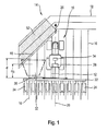
- Figure 1 shows an agricultural machine 10 in the form of a tractor with an implement 12 in a top view during the working or a row culture 14, wherein the implement 12 is arranged at the rear end of the agricultural machine 10.
- An agricultural machine 10 can for example also be a self-propelled sprayer, which outputs pesticide with its implement 12.
- the row culture 14 is arranged in working rows 16 and interference rows 18, wherein the working rows 16 represent the rows of the row culture, which are worked by the agricultural machine 10 and the implement 12, while the working rows 16 are substantially arranged parallel to one another.
- the working rows 16 are the rows of the row culture, which during the working are substantially arranged parallel to a travelling direction 20 of the agricultural machine 10.
- the interference rows 18 are arranged at an angle to the working rows 16, for example in the region of a headland, as a result of which the implement 12 on reaching the interference rows 18 and/or at each end of a working row 16 has to be brought out of engagement in order to avoid damaging the plants in the interference rows 18.
- these rows are the working rows 16, since they are then substantially arranged parallel to the travelling direction 20 of the agricultural machine 10.
- Working the row culture 14, in particular the working rows 16, can for example be effected by a sowing machine, or as shown in Figure 1 , by means of an implement 12 in the form of a mechanical hoe for the mechanical weeding between the working rows 16 of the row culture 14.
- the shown implement 12 comprises a controllably moveable working section 22, on which a multiplicity of working devices 24, for example duckfoot shares and/or disc shares for mechanical soil cultivation are arranged.
- the number of working devices 24 can be dependent on the width of the implement 12 and/or of the working section 22 as well as the working rows 16 to be worked simultaneously and/or intermediate spaces between the working rows 16.
- the working devices 24 can be activatable or deactivatable individually or in groups, for example for each working section.
- An activated working device 24 in this case is arranged for working the row culture and/or activatable, a deactivated working device 24 is not utilisable for working the row culture 14, wherein for example during mechanical soil cultivating a deactivated working device 24 can be pivoted in such a manner that the working devices 24 have no contact with the row culture 14 or the soil.
- the working section 22 can be moved transversely to a longitudinal axis 26 and/or the travelling direction 20 of the agricultural machine 10, as a result of which an improved orientation of the working section and/or of the working devices relative to the working rows 16 can be achieved.
- the agricultural working machine 10 comprises a control unit 28 for controlling the movement of the working section 22 relative to at least one working row 16.
- the control unit 28 can likewise control the working devices 24, in particular the activation, deactivation as well as a pivoting of the working devices 24.
- the control unit 28 is connected to an optical sensor unit 30, which is arranged on the implement 12 on the working section 22.
- the control unit 28 can also be integrated in an optical sensor unit 30.
- the optical sensor unit 30 can for example be a digital camera or a 3D-camera.
- the optical sensor unit 30 detects a part region of the row culture 14 in a field of view 32, in particular in travelling direction 20, wherein the optical sensor unit 30 generates an image of the detected part region of the row culture 14.
- the field of view 32 of the optical sensor unit 30 can be orientated looking ahead in travelling direction 20 of the agricultural machine 10 and detect a region in travelling direction in front of the actual working section 22.
- the generated image can for example be processed by means of an image detection, wherein a spatial orientation of the row culture 14, in particular of the working rows 16 and possibly present interference rows 18, can be detected.
- a sensor signal S for controlling the working section 22 and/or working devices 24 can be generated by the optical sensor unit 30 and/or the control unit 28. Because of this, an optical control of the working section 22 along at least one working row 16 can be ensured, wherein the working section 22 can be precisely guided along the actual position of the working row 16.
- the interference row 18 which is arranged at an angle to the working rows 16 to be worked, can increasingly enter the field of view 32 of the optical sensor unit 30.
- the sensor signal S which is generated based on the image of the field of view 32 of the optical sensor unit 30, can lead to a defective control of the working section 22 and/or of the working devices 24, since the control unit 28 can attempt for example to move the working section 22 corresponding to the orientation of the interference rows 18, when damages of the working rows 16 can occur.
- the generated sensor signal S can lead to an unfavourable control of the working section 22 and/or working device 24, since in travelling direction 20 beyond the end of the working rows 16 no optical orientation points for generating a reliable sensor signal S are present.
- the validity of the sensor signal S can be evaluated through the control unit 28 with the help of at least one evaluation parameter. If the validity, the control unit 28 in this case evaluates the extent to which the sensor signal S can be utilised for a reliable control of the working section 22 and/or of the working device 24, wherein the validity can be understood as the validity or accuracy of the sensor signal S. Thus, a very high validity of the sensor signal S can be given in the case that working rows 16 are exclusively detected and depicted in the field of view 32 of the optical sensor unit 30.
- the sensor signal S for example can be evaluated with a low validity since the sensor signal S for the control of the working section 22 and/or working device 24 becomes increasingly inaccurate because of the increasing component of interference rows 18.
- the control unit 28 can take into account a sensor signal S with a low validity to a lesser degree and consider further signals, for example from a navigation system, to a greater degree for the control.
- the sensor signal S can be completely disregarded and/or the optical sensor unit 30 can for example be switched off in order to avoid faulty controlling of the working section 22 and/or working device 24.
- the at least one evaluation parameter for evaluating the validity of the sensor signal S can be a parameter, which exerts influence on the validity, or accuracy of the sensor signal S.
- Evaluation parameters can for example be an adequate optical contrast between the row culture 14 and the ground, gaps in the working rows 16, the size of the distances between the working rows 16, or the spatial arrangement of the working rows 16 and/or interference rows 18.
- a distance d between the optical sensor unit 30 and an interference row 18 and/or an end of a working row 16 is employed as evaluation parameter for evaluating the validity of the sensor signal S.
- the agricultural machine 10 shown in Figure 1 with the attached implement 12 is moved in travelling direction 20 along the working rows 16, while the working machine 10 approaches interference rows 18 which can represent a headland.
- an optical sensor unit 30 is arranged on the in travelling direction 20 left side facing the interference rows, the field of view 32 of which detects the first interference row 18.
- the distance between the optical sensor unit and the end of a working row 16 substantially corresponds to the distance between the optical unit 30 and the closes interference row 18.
- the optical sensor unit 30 and the closest interference row 18 are spaced by a distance d along a working row 16. Along each working row 16, a distance d can thus be determined between the optical sensor 30 and an interference row 18 and/or an end of the respective working row 16.
- the validity of the sensor signal S can be evaluated through the distance d as evaluation parameter.
- a limit distance d G can be adjusted for example by an operator of the machine 10, with which the distance d can be in particular continuously compared.
- the limit distance d G can for example be stored in the control unit 28.
- the sensor signal S can be evaluated by the control unit 28 with a low validity or be disregarded for the control.
- a plurality of in particular stepped limit distances dg can also be adjustable, wherein each limit distance d G can correspond to another validity, for example the validity of the sensor signal S can be correspondingly decreased with decreasing limit distances d G .
- the optical sensor unit 30 can be switched off in order to avoid faulty controlling because of the influence of the interference rows 18 on the sensor signal S.
- the control unit 28 for example in the case that only a single optical sensor unit 30 is present, can fix the control of the working section 22 and/or working device 24 in the case of two low a validity of the sensor signal S, so that the working rows 16 can be finish-worked free of defects.
- Figure 2 shows an agricultural machine 10 with an implement 12, which comprises a working section 22 that can be moved transversely to the longitudinal axis 26 of the machine 10.
- a working section 22 that can be moved transversely to the longitudinal axis 26 of the machine 10.
- two optical sensor units 30 are arranged next to a plurality of working devices 24, wherein on each side of the longitudinal axis 26 an optical sensor unit 30 is arranged.
- the field of view 32 of the respective sensor unit 30 in travelling direction 20 is directed towards the front, wherein in each case a part region of the row culture 14 can be detected and depicted.
- the machine 10 is moved in travelling direction 20 along a plurality of working rows 16 and approaches interference rows 18, which for example can constitute a headland.
- the interference rows 18 are arranged at an angle that is smaller than 90° to the working rows 16 and in a region on the right-hand side at an angle of approximately 90° to the working rows 16. Because of this, the working machine 10 and the left-hand side optical sensor unit 30 approach the interference rows 18 faster on the left-hand side than on the right-hand side, so that the distance d of the optical sensor unit 30 which is arranged on the left-hand side of the longitudinal axis 26 decreases before the distance d of the optical sensor unit 30 arranged on the right-hand side. Owing to the arrangement of the interference rows 16, the distance d 1 initially decreases along the working row 16 located furthest, in this case left-hand, outside.
- the control unit 28 receives a sensor signal S each from the optical sensor units 30, which can be used for controlling the working section 22 and/or working device 24.
- the sensor unit 30 arranged on the left-hand side may generate a sensor signal S 1 and the sensor unit 30 arranged on the right-hand side may generate a sensor signal S 2 .
- the control unit 28 initially evaluates the validity of the sensor signals S 1,2 of the sensor unit 30 arranged on the left-hand side and right-hand side, wherein on reaching a preadjustable limit distance d G between an optical sensor unit 30 and an interference row 18, a sensor signal S 1,2 with a low validity can be evaluated or be entirely disregarded for the control. In the situation shown in Fig.
- the limit distance d G of the left optical sensor unit 30 would be initially undershot, so that the sensor signal S 1 of the left optical sensor unit 30 could be evaluated with a lower validity than the sensor signal S 2 of the right optical sensor unit 30, so that the control unit 28 would put more weight on the right sensor signal S 2 or utilise it exclusively for controlling the working section 22. Accordingly, in the case of more than two sensor signals S, the control unit 28 can put less weight on the low-evaluated sensor signals S for controlling or disregard them entirely.
- control unit 28 can for example disregard both control signals S 1,2 and fix the control and/or the working section 22 until the working devices 24 reach the interference rows 18 or the ends of the working rows 16 and are correspondingly deactivated by the control unit 28.
- the optical sensor unit 30 can also hide a region 52, in particular a region 52 that is arranged further distant from the sensor unit 30 than the limit distance d G , disregarding it for the generation of the sensor signal S, for example of the sensor signals S 1,2 .
- the hidden region 52 can extend along the interference rows 18, for example in the form of a headland. Through the hidden region 52, the influence of the interference rows 18 on the sensor signal S can be reduced. With increasing approach of the limit distance, the hidden region 52 can become continuously larger and the depicted region of the field of view 32 used for the sensor signal S can become continuously smaller so that the image information that is available for generating the sensor signal S becomes ever less so that the validity of the sensor signal S likewise decreases with decreasing distance.
- the sensor signals S 1,2 of the two optical sensor units 30 can be fused into one sensor signal S T after their respective evaluation, in particular by the control unit 28, on the basis of which the control unit 28 can control the working section 22.
- a plurality of in particular evaluated sensor signals S of a corresponding number of optical sensor units 30 can also be fused into a single sensor signal S T .
- the evaluated sensor signals S V can for example be averaged, while sensor signals S V with a validity below a limit value can be disregarded.
- the agricultural machine 10 can comprise an in particular satellite-supported navigation system 34, which is connected to the control unit 28.
- the navigation system 34 can for example be equipped in order to be usable for route planning and/or automatic control of the agricultural machine 10.
- the navigation system 34 can transmit position signals P for the position-dependent control of the working devices 24 for working the row culture 14 to the control unit 28. Because of this, the working devices 24 can be activated or deactivated individually or in groups dependent on position in a so-called part width control.
- data in particular position data, at least regarding the row culture 14 to be worked, can be stored.
- the stored data can for example be position information regarding a spatial arrangement of working rows 16, interference rows 18 and/or ends of the working rows 16.
- the navigation system 34 can transmit a position signal P to the control unit 28, from which the distance d for example of an optical sensor unit 30 to an interference row 18, in particular along a certain working row 18, can be determined.
- the distance d in this case can be measured perpendicularly to the working section 22 along one or a plurality of working rows 16 in each case.
- the distance d of an optical sensor unit 30 for example to an interference row 18 can be equal to the distance d of the working section 22 to the interference row 18.
- the geometrical configuration and the arrangement of the optical sensor unit 30 and of the working devices 24 can be stored in particular in the control unit 28.
- the distance d between an optical sensor unit 30 and an interference row 18 and/or the end of a working row 16 can also be determined with the optical sensor unit 30, for example with an optical sensor unit 30 in the form of a 3D-camera, which provides spatial distance data to objects in its field of view 32.
- the control unit 28 can also determine a length of the respective working rows 16 and/or distances d in particular from data regarding the respective activation of the working devices 24, for example the position in which these are to be activated and deactivated, stored in the control unit 28.
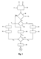
- Figure 3 shows a flow diagram, which exemplarily illustrates the evaluation of the validity of two sensor signals S 1,2 .
- the sensor signals S 1,2 in this case originate from two optical sensor units 30 shown in figure 2 , wherein the optical sensor unit 30 arranged on the left-hand side in the travelling direction may generate the sensor signal S 1 and the optical sensor unit 30 arranged on the right-hand side may generate the sensor signal S 2 .
- Shown is a simplified embodiment of the method according to the invention, wherein the evaluation of the validity of a sensor signal S takes place by means of the distance d as evaluation parameter, in order to generate an evaluated sensor signal S V .
- the distance d in this case is determined by means of at least one position signal P, which is provided by the navigation system 34 based on the current position and stored information.
- a first event step 36 the respective distance d between an optical sensor unit 30 and the ends of the working rows 16 located in front of it and/or the interference rows 18, in particular of the closest interference row 18, is determined from the at least one position signal P for evaluating the validity of the sensor signals S 1,2 .
- the determined distances d along the working rows 16 under consideration are each compared with at least one preadjusted limit distance d G . If no distance d is smaller than the adjusted limit distance d G , each sensor signal S 1,2 can each be assigned a corresponding, for example high value of the validity in a second event step 40.
- a high validity of the sensor signal S 1,2 may be assumed if the risk of a defective control of the working section 22 may be considered low because of the determined distances to interference rows 18 and/or ends of the working rows 16.
- further evaluation parameters for example the optical contrast between the recognised working rows 16 and the ground can be utilised for evaluating the validity of the sensor signals S 1,2 , in order to take into account further influences on the validity of a sensor signal S.
- the sensor unit 30 which is assigned the determined distance d which undershoots the limit distance d G is determined in a second decision step 42. This can be determined for example by determining the optical sensor unit 30 which is assigned the field of view 32, in which the respective working row 16 is arranged, along which the distance d is smaller than the limit distance d G .
- the limit distance d G is initially not undershot along any of the working rows 16 detected by the optical sensor units 30. However, if the machine 10 is moved further in travelling direction 20, the distance d along the working row 16 arranged on the left outside will first undershoot the limit distance d G , which is in the field of view 32 of the left optical sensor unit 30. It can thus be determined that the sensor signal S 1 of the left optical sensor unit 30 is affected.
- the optical sensor unit 30, for example in Figure 2 the left sensor unit 30, may hide the region 52 field of view 32 for generating the sensor signal S 1 , which is in the region of the detected interference rows 18 or in particular on the other side of the limit distance d G , in order to avoid interfering influences of the interference rows on the control of the working section.
- the image of the row culture used for generating the sensor signal S 1 of this optical sensor 30 is reduced in size because of this, as a result of which the validity of the corresponding sensor signal S 1 is reduced.
- the utilisable image in the field of view 32 of the optical sensor unit 30 is reduced further, so that the validity of the sensor signal S 1 likewise further decreases.
- the value of the validity of the affected sensor signal S 1,2 is assigned to the sensor signal S 1,2 in a fourth event step 46, in order to generate an accordingly evaluated sensor signal S V1,2 , while with a decreasing distance d the value of the validity may decrease.
- a third decision step 48 the values of the validity assigned to the sensor signals S V1,2 are compared with a validity limit value. If the validity limit value is undershot by an evaluated sensor signal S V1,2 , the validity of this sensor signal S V1,2 is set equal to zero, as a result of which this sensor signal S V1,2 is disregarded by the control unit for controlling the working section.
- the evaluated sensor signals S V1,2 which have a greater validity than the validity limit value, are fused into a single total sensor signal S T in a fifth event step 50.
- the sensor signals S V1,2 may be averaged into a total sensor signal S T for the control taking into account their respective validity.
- a cross track error which in particular in each case may be determined by the optical sensor units 30, may be additionally taken into account for generating a control signal S, S V in the fifth event step 50.
- the product with the corresponding validity of the sensor signal S V for example from the sensor signals S 1,2 , may be formed from each of the determined cross track errors. Owing to the validity limit value, cross track errors, which are assigned to a sensor signal S V with low validity, are disregarded by the control.
- the fused sensor signal S T so generated serves as basis for controlling the working section 22 and/or working devices 24 along the working rows 16 for the control unit 28.
- FIG 4 shows an agricultural machine 10, the implement 12 of which comprises three individually moveable working sections 22, wherein on each working section 22 an optical sensor unit 30 is arranged.
- each optical sensor unit 30 may generate a sensor signal S, for example the sensor signals S 1 , S 2 and S 3 , for controlling each respective working section 22, on which it is arranged.
- the sensor signals S of the three optical sensor units 30 may also be partly and/or jointly utilised by the control unit 28 for controlling individual and/or all working sections 22 and/or working devices 24.
- a reliable sensor signal S T for the control may be generated by the remaining two sensor units 30 and their evaluated sensor signals S V , for example sensor signals S V2,3 , when the validity of a sensor signal S of a sensor unit 30, for example sensor signal S 1 , is reduced.
- FIG. 5 An arrangement of a working device 24 each on a working section 22 is shown in Figure 5 .
- the working devices 24 are individually controllable along a working row 16 because of this, as a result of which a more precise working of the row culture 14 can be achieved.
- the control is effected via the control unit 28, which is connected to three optical sensor units 30, which generate a sensor signal S each.
- the sensor signals S 1,2 , 3 of the optical sensor units 30 may be used individually or combined for controlling certain or all working sections 22 and/or working devices 24.
Abstract
Description
- The present invention relates to an agricultural machine with a controllably moveable implement for working row cultures, and to a method for controlling an agricultural machine with an implement having at least one controllably moveable section.
- Agricultural machines for working row cultures usually comprise an implement, which is arranged transversely to a travelling direction or a longitudinal axis of the machine and a plurality of working devices for working the plants of the row culture arranged in rows. The working devices can be equipped for mechanically or contactlessly working the row culture, for example for outputting fertiliser or pesticides. The agricultural machines in this case frequently have a part width control, in which the working devices can be activated individually or in groups, so that with overlapping working strips plant rows or individual plants of the row culture are each worked only once in order to avoid for example over-fertilising or mechanically damaging the row culture. Controlling the part width shutoff can be effected manually by an operator of the agricultural machine or automatically, for example through a control unit that is coupled in particular to a navigation system. For improving the working of the row culture, a section control of the implement can be provided, in which working devices combined into sections are moveable transversely to the travelling direction of the machine so that the working devices can be better guided along the plants of the row culture.
- From
EP 2 342 963 A1 - It is therefore the object of the invention to provide an agricultural machine and a method which make possible an improvement of the control of a working section and/or working device of an implement of an agricultural machine in the working of a row culture, in particular in a region of irregularly arranged rows of plants.
- According to the invention, the object is solved through the characterising features of
patent claims 1 and 9. Advantageous configurations and further developments of the invention are obtained from the following subclaims and the following descriptions. - An agricultural machine according to the invention comprises an implement for working a row culture, wherein the row culture substantially comprises working rows arranged parallel to one another and/or interference rows arranged at an angle to the working rows and wherein the implement comprises at least one controllably moveable working section with at least one activatable working device for working the row culture, a control unit for controlling the at least one working section and/or working device relative to at least one working row, and at least one optical sensor unit connected to the control unit for generating an image of at least one part of the row culture, wherein based on the image of the row culture a sensor signal for controlling the working section and/or working device is generatable, wherein the control device is equipped and designed in such a manner as to evaluate a validity of the sensor signal for controlling the at least one working section and/or working device based on at least one evaluation parameter.
- With the validity, the control unit valuates the extent to which a sensor signal is utilisable for a reliable control of the working section and/or of the working device. Validity of the sensor signal in this case is to mean the validity or accuracy of the sensor signal. Evaluation parameters for evaluating the validity of the sensor signal can be parameters such as exert an influence on the validity or accuracy of the sensor signal. The optical detection of the row culture with an optical sensor unit makes possible a highly precise guiding of the implement and/or of the working devices along at least one row culture. The evaluation of the validity of the sensor signal has the advantage that an interfering influence of an interference row on the control can be reduced, as a result of which the control of the working section and/or working device in the working of a row culture can be improved.
- An agricultural machine, for example a tractor or a self-propelled pesticide sprayer, comprises an implement, which substantially extends transversely to the travelling direction and/or a longitudinal axis of the machine. The implement in this case can span a plurality or rows of the row culture to be worked, wherein the plants can be arranged in working rows and/or interference rows. The working rows are substantially arranged parallel to the travelling direction and/or longitudinal direction of the machine and are the plant rows to be worked at that time. Here, the plants of the working rows, can be worked for example with pesticide, and/or the soil between the working rows, be worked for example with an implement in the form of a mechanical hoe for the mechanical weeding in row cultures. Interference rows are arranged at an angle to the working rows, for example the plant rows arranged in a headland, and cannot be worked in the same operation as the working rows without being worked twice or damaged in the process. During the working of the plant rows in the headland, the plant rows in the headland to be processed then constitute the working rows and the plant rows which are arranged at an angle thereto, constitute the interference rows. The implement comprises at least one controllably moveable working section, wherein on the working section at least one working device for working the plants in the working rows and/or the soil between the working rows can be arranged. Moving the working section can be effected through a control unit substantially controlled perpendicularly to the travelling direction and/or longitudinal axis of the machine, as a result of which a guidance of the at least one working devices along a working row can be improved. The control of the working section and/or working device can take place based on a sensor signal, for the generation of which an optical sensor unit, which is connected to the control unit, generates an image of at least one part of the row culture. The sensor signal can be generated through the optical sensor unit and/or through the control unit. The sensor signal can for example contain information obtained for example through image evaluation with respect to the arrangement, in particular the working rows and interference rows, of the row culture, which are utilisable by the control unit for controlling the working section and/or working device. The control unit can be connected to the optical sensor unit and further sensor units, for example a navigation system and/or an automatic steering system, the signals of which are likewise utilisable by the control unit for controlling the working section and/or the working device. By means of the control signal, the control unit can precisely control the working section and/or working device in the case of a machine moving in travelling direction relative to the working rows detected through the image. Here, the control unit evaluates a validity of the sensor signal for controlling the at least one working section and/or working device with the help of at least one evaluation parameter. With the validity, the control unit evaluates the extent to which the sensor signal is utilisable for a reliable control of the working section and/or the working device. The validity of the sensor signal in this case is to mean the validity or accuracy of the sensor signal. In the case of an evaluation of the sensor signal, which produces for example a high validity of the sensor signal, the control unit can control the working section and/or the working device along a working row based on the sensor signal. For a sensor signal with a low validity, the control unit could take into account the sensor signal to a lesser degree and take into account further signals, for example from a navigation system, to a greater degree. If the evaluation produces a very low validity of the sensor signal, the sensor signal can be entirely neglected and/or the optical sensor unit deactivated. Evaluation parameters for evaluating the validity of the sensor signal can be such parameters as exert an influence on the validity or accuracy of the sensor signal, for example row culture-based and/or working machine-based parameters, the light conditions under which the optical sensor unit generates the image, an adequate optical contrast between the row culture and the soil, gaps in the plant rows, the size of the spacings between the working rows, or the spatial arrangement of the working rows.
- In a preferred configuration of the invention, the evaluation parameters are a distance between the at least one optical sensor unit and at least one interference row and/or at least one end of a working row. The evaluation parameter can be the distance between the optical sensor unit and an end of a working row, wherein the distance between the optical sensor unit and an end of each working row can be determinable in the field of view of the optical sensor unit. The distance to the optical sensor unit in this case can correspond to the distance to the working section and/or the working device. Furthermore, the evaluation parameter can be the distance between the optical sensor unit and at least one interference row, wherein the interference row is arranged at an angle to a working row and can intersect the working row or working rows, for example at a headland, wherein the working rows can each end at the interference row. Here, the distance between the optical sensor unit and the interference row located next to the sensor unit can correspond to the distance between the sensor unit and the end of the respective working row. Because the distance between the optical sensor unit and an end of a working row and/or an interference row is taken into account as evaluation parameter in the evaluation of the validity of the sensor signal it can be avoided that the working section and/or working device are wrongly activated. In the case of an increasing number of interference row in the field of view of the optical sensor unit, the interference rows because of their oblique arrangement to the working rows can lead to a distorted control signal, which in turn can lead to a defective activation of the working section and/or working device, since the control unit could attempt to align the working section and/or working device parallel to the interference rows, as a result of which the working rows which are still to be worked could be effectively worked or destroyed. By taking into account the distance, the validity of the sensor signal with decreasing distance to an interference row or an end of a working row can be lowered in order to compensate for an increase of detected interference rows or missing rows, as at an end of a working row. It is particularly advantageous that by doing so the control can be improved in regions of irregularly arranged plant rows, for example interference rows of a headland.
- In a particularly preferred configuration of the invention, a limited distance between the optical sensor unit and at least one interference row and/or an end of a working row is adjustable for evaluating the sensor signal. Through the adjustable limit distance, a certain distance can be predetermined in the case of which the validity of the sensor signal can be significantly lowered or the sensor signal is disregarded by the control unit for the further control of the working section and/or working device. This has the advantage that the evaluation of the sensor signal through the control unit can be simplified.
- Advantageously, a part region of the image of the row culture, in particular a distance-dependent one, can be evaluated through the control unit. For evaluating a part region of the image of the row culture, the sensor signal can be generated based on the part region to be evaluated or merely the part of the sensor signal which corresponds to the part region to be considered be utilised for the evaluation. In the case of an adjusted limit distance, only a part region of the image which is arranged on the sensor side of the limit region can be considered for example by the sensor unit and/or the control unit.
- In a particularly advantageous configuration of the invention, the machine comprises a navigation system connected to the control unit, wherein the distance between the optical sensor unit and at least one interference row and/or the end of at least one working row can be determined by means of the navigation system. The navigation system can for example be a satellite-supported navigation system for determining the current position of the agricultural machine, an optical sensor unit and/or the working device. The navigation system can be employed for activating the at least one working device, for example by providing current and/or stored position signals to the control unit for the position-dependent activation of the working devices. In the navigation system, data for row cultures can be stored, for example the spatial arrangement of working rows and interference rows, as well as the positions of the ends of the working rows. Through the navigation system, the distance between the optical sensor unit and an interference row and/or the end of a working row can be determined in a particularly simple manner.
- In a further advantageous configuration of the invention, the distance between the optical sensor unit and at least one interference row and/or the end of at least one working row can be determined by means of the optical sensor unit. An optical sensor unit that is present for controlling the working section and/or working device can be employed particularly cost-effectively for determining the distance for example by means of an image evaluation for detecting an interference row and/or an end of a working row.
- In an advantageous configuration, at least one second optical sensor unit for creating a second image is provided, wherein based on the second image a second sensor signal can be generated, and the, in particular evaluated, sensor signals can be utilised individually or in combination for controlling the at least one working section and/or working device. The second image can detect at least one part of the row culture. The first image and the second image can detect different, partly different or the same part of the row culture. Through the second image, a second sensor signal for controlling the at least one working section and/or working device can be provided through the optical sensor unit and/or the control unit. Advantageously, the first and the second, in particular evaluated, sensor signal can be jointly utilised for the control. Here, the sensor signals can be evaluated differently and be incorporated in the control of the at least one working section and/or working device corresponding to their respective evaluation. Here, a sensor signal with low validity can be disregarded, so that the control is based on the second sensor signal. For example, the first sensor signal can be evaluated with a low validity because of an interference row, while the second sensor signal is evaluated with a very high validity, so that the control of the at least one working section and/or working device by means of a sensor signal is predominantly or exclusively based on the second sensor signal. Because of this, a sensor signal of low validity can be compensated for, as a result of which a reliable control can be ensured for longer.
- Furthermore, the invention relates to a method for controlling a working section and/or working device of an implement of an agricultural machine for working a row culture, wherein the row culture comprises working rows substantially arranged parallel to one another and/or interference rows arranged at an angle to the working rows, and wherein the implement comprises at least one controllably moveably working section with at least one activatable working device for working the row culture, a control unit for controlling the at least one working section and/or working device relative to at least one working row, and at least one optical sensor unit connected to the control unit for generating an image of at least one part of the row culture, wherein based on the image of the row culture a sensor signal for controlling the working section and/or working device is generated. According to the invention, the control unit evaluates the sensor signal for controlling the at least one working section and/or working device based on at least one evaluation parameter. The optical detecting of the row culture makes possible a highly precise guiding of the working machine and/or of the implement along at least one row culture. The evaluation of the validity of the sensor signal makes possible a further improvement of the control of the working section and/or working device during the working of a row culture.
- In a preferred further development, the sensor signal is evaluated based on a distance between the at least one optical sensor unit and at least one interference row and/or at least one end of a working row. By detecting the distance between the at least one optical sensor unit and at least one interference row and/or an end of a working row, the validity of the sensor signal can be lowered with decreasing distance to an interference row or an end of a working row in order to compensate for a rise of detected interference rows or missing rows, as at an end of a working row. It is particularly advantageous that because of this the control can be improved in regions of irregularly arranged plant rows, for example at a headland.
- In a further configuration, a limit distance between the optical sensor unit and at least one interference row and/or an end of a working row is adjusted for evaluating the sensor signal. Through the adjustable limit distance, a certain distance can be predetermined at which for example the validity of the sensor signal can be significantly lowered or the sensor signal be disregarded by the control unit for the further control of the working section and/or working device. This has the advantage that the evaluation of the sensor signal through the control unit can be simplified.
- Preferentially, an, in particular distance-dependent, part region of the image of the row culture is evaluated through the control unit. In the case of an adjusted limit distance, only a part region of the image which is arranged on the sensor side of the limit region can be taken into account by the sensor unit and/or the control unit.
- Particularly preferably, the distance between the optical sensor unit and an interference row and/or the end of at least one working row is determined by means of a navigation system and/or an optical sensor unit. Through the navigation system, the distance between the optical sensor unit and an interference row and/or the end of a working row can be determined in a particularly simple manner. An optical sensor unit that is present for controlling the working section and/or working device can be particularly cost-effectively employed for determining the distance, for example by means of an image evaluation for detecting an interference row and/or an end of a working row.
- In a further preferred configuration of the invention, at least one second optical sensor unit is provided for generating a second image, wherein based on the second image a second sensor signal can be generated, and the, in particular evaluated, sensor signals are utilised individually and/or in combination for controlling the at least one working section and/or working device. Through the second optical sensor unit and the second sensor signal, the detected field of view of the optical sensor units can be enlarged, as a result of which the accuracy of the control can be improved, and a sensor signal of low validity can be compensated by a further, a second, sensor signal, as a result of which a reliable control can be ensured for longer.
- Further features and advantages of the invention are obtained from the following description of exemplary embodiments making reference to the attached figures.
- It shows:
- Fig. 1:
- a schematic top view of an agricultural machine with an implement having a moveable working section and two optical sensor units;
- Fig. 2:
- a schematic top view of a machine having a moveable working section and two optical sensor units;
- Fig. 3:
- a flow diagram, which exemplarily illustrates the evaluation of the validity of two sensor signals;
- Fig. 4:
- a top view of a machine having three working sections with an optical sensor unit each; and
- Fig. 5:
- a top view of a machine having three optical sensor units and more than three moveable working sections.
-
Figure 1 shows anagricultural machine 10 in the form of a tractor with an implement 12 in a top view during the working or arow culture 14, wherein the implement 12 is arranged at the rear end of theagricultural machine 10. Anagricultural machine 10 can for example also be a self-propelled sprayer, which outputs pesticide with its implement 12. Therow culture 14 is arranged in workingrows 16 andinterference rows 18, wherein the workingrows 16 represent the rows of the row culture, which are worked by theagricultural machine 10 and the implement 12, while the workingrows 16 are substantially arranged parallel to one another. The workingrows 16 are the rows of the row culture, which during the working are substantially arranged parallel to a travellingdirection 20 of theagricultural machine 10. Theinterference rows 18 are arranged at an angle to the workingrows 16, for example in the region of a headland, as a result of which the implement 12 on reaching theinterference rows 18 and/or at each end of a workingrow 16 has to be brought out of engagement in order to avoid damaging the plants in theinterference rows 18. When working the plants in the headland, these rows are the workingrows 16, since they are then substantially arranged parallel to the travellingdirection 20 of theagricultural machine 10. - Working the
row culture 14, in particular the workingrows 16, can for example be effected by a sowing machine, or as shown inFigure 1 , by means of an implement 12 in the form of a mechanical hoe for the mechanical weeding between the workingrows 16 of therow culture 14. The shown implement 12 comprises a controllably moveable workingsection 22, on which a multiplicity of workingdevices 24, for example duckfoot shares and/or disc shares for mechanical soil cultivation are arranged. The number of workingdevices 24 can be dependent on the width of the implement 12 and/or of the workingsection 22 as well as the workingrows 16 to be worked simultaneously and/or intermediate spaces between the workingrows 16. The workingdevices 24 can be activatable or deactivatable individually or in groups, for example for each working section. An activated workingdevice 24 in this case is arranged for working the row culture and/or activatable, a deactivated workingdevice 24 is not utilisable for working therow culture 14, wherein for example during mechanical soil cultivating a deactivated workingdevice 24 can be pivoted in such a manner that the workingdevices 24 have no contact with therow culture 14 or the soil. The workingsection 22 can be moved transversely to alongitudinal axis 26 and/or the travellingdirection 20 of theagricultural machine 10, as a result of which an improved orientation of the working section and/or of the working devices relative to the workingrows 16 can be achieved. The agricultural workingmachine 10 comprises acontrol unit 28 for controlling the movement of the workingsection 22 relative to at least one workingrow 16. Thecontrol unit 28 can likewise control the workingdevices 24, in particular the activation, deactivation as well as a pivoting of the workingdevices 24. - The
control unit 28 is connected to anoptical sensor unit 30, which is arranged on the implement 12 on the workingsection 22. Thecontrol unit 28 can also be integrated in anoptical sensor unit 30. Theoptical sensor unit 30 can for example be a digital camera or a 3D-camera. Theoptical sensor unit 30 detects a part region of therow culture 14 in a field ofview 32, in particular in travellingdirection 20, wherein theoptical sensor unit 30 generates an image of the detected part region of therow culture 14. The field ofview 32 of theoptical sensor unit 30 can be orientated looking ahead in travellingdirection 20 of theagricultural machine 10 and detect a region in travelling direction in front of the actual workingsection 22. The generated image can for example be processed by means of an image detection, wherein a spatial orientation of therow culture 14, in particular of the workingrows 16 and possiblypresent interference rows 18, can be detected. Based on the image of the part region of therow culture 14, a sensor signal S for controlling the workingsection 22 and/or workingdevices 24 can be generated by theoptical sensor unit 30 and/or thecontrol unit 28. Because of this, an optical control of the workingsection 22 along at least one workingrow 16 can be ensured, wherein the workingsection 22 can be precisely guided along the actual position of the workingrow 16. - When the
agricultural machine 10 with the implement 12 approaches aninterference row 18, for example in the region of a headland, theinterference row 18, which is arranged at an angle to the workingrows 16 to be worked, can increasingly enter the field ofview 32 of theoptical sensor unit 30. Through the arrangement of theinterference row 18 which is not parallel to the workingrows 16, the sensor signal S, which is generated based on the image of the field ofview 32 of theoptical sensor unit 30, can lead to a defective control of the workingsection 22 and/or of the workingdevices 24, since thecontrol unit 28 can attempt for example to move the workingsection 22 corresponding to the orientation of theinterference rows 18, when damages of the workingrows 16 can occur. Likewise, when theagricultural machine 10 with the implement 12 approaches one or a plurality of ends of the workingrows 16, in particular withoutinterference rows 18, the generated sensor signal S can lead to an unfavourable control of the workingsection 22 and/or workingdevice 24, since in travellingdirection 20 beyond the end of the workingrows 16 no optical orientation points for generating a reliable sensor signal S are present. - To improve the control of the working
section 22 and/or workingdevice 24, the validity of the sensor signal S can be evaluated through thecontrol unit 28 with the help of at least one evaluation parameter. If the validity, thecontrol unit 28 in this case evaluates the extent to which the sensor signal S can be utilised for a reliable control of the workingsection 22 and/or of the workingdevice 24, wherein the validity can be understood as the validity or accuracy of the sensor signal S. Thus, a very high validity of the sensor signal S can be given in the case that workingrows 16 are exclusively detected and depicted in the field ofview 32 of theoptical sensor unit 30. If, by contrast, the number of the detected and depictedinterference rows 18 increases, for example when the agricultural workingmachine 10 approaches theoptical sensor 30, the sensor signal S for example can be evaluated with a low validity since the sensor signal S for the control of the workingsection 22 and/or workingdevice 24 becomes increasingly inaccurate because of the increasing component ofinterference rows 18. Thus, thecontrol unit 28 can take into account a sensor signal S with a low validity to a lesser degree and consider further signals, for example from a navigation system, to a greater degree for the control. On undershooting an adjustable limit value of the validity, the sensor signal S can be completely disregarded and/or theoptical sensor unit 30 can for example be switched off in order to avoid faulty controlling of the workingsection 22 and/or workingdevice 24. - The at least one evaluation parameter for evaluating the validity of the sensor signal S can be a parameter, which exerts influence on the validity, or accuracy of the sensor signal S. Evaluation parameters can for example be an adequate optical contrast between the
row culture 14 and the ground, gaps in the workingrows 16, the size of the distances between the workingrows 16, or the spatial arrangement of the workingrows 16 and/orinterference rows 18. Preferably, a distance d between theoptical sensor unit 30 and aninterference row 18 and/or an end of a workingrow 16 is employed as evaluation parameter for evaluating the validity of the sensor signal S. - The
agricultural machine 10 shown inFigure 1 with the attached implement 12 is moved in travellingdirection 20 along the workingrows 16, while the workingmachine 10 approachesinterference rows 18 which can represent a headland. On the workingsection 22 of the implement 12 anoptical sensor unit 30 is arranged on the in travellingdirection 20 left side facing the interference rows, the field ofview 32 of which detects thefirst interference row 18. In the representation, the distance between the optical sensor unit and the end of a workingrow 16 substantially corresponds to the distance between theoptical unit 30 and thecloses interference row 18. Theoptical sensor unit 30 and theclosest interference row 18 are spaced by a distance d along a workingrow 16. Along each workingrow 16, a distance d can thus be determined between theoptical sensor 30 and aninterference row 18 and/or an end of the respective workingrow 16. The further themachine 10 moves on in travellingdirection 20, the smaller the distances d become, in particular in the field ofview 32 of theoptical sensor unit 30, along the workingrows 16 and the fewer workingrows 16 are available for generating a valid sensor S, as a result of which the validity of the sensor signal S likewise decreases with decreasing distances. Thus, the validity of the sensor signal S can be evaluated through the distance d as evaluation parameter. - For the distance d, a limit distance dG can be adjusted for example by an operator of the
machine 10, with which the distance d can be in particular continuously compared. The limit distance dG can for example be stored in thecontrol unit 28. On reaching the limit distance dG along a working row, or in the mean of all workingrows 16 detected by theoptical sensor 30, the sensor signal S can be evaluated by thecontrol unit 28 with a low validity or be disregarded for the control. A plurality of in particular stepped limit distances dg can also be adjustable, wherein each limit distance dG can correspond to another validity, for example the validity of the sensor signal S can be correspondingly decreased with decreasing limit distances dG. In addition, in the case of a very low validity or a negligible sensor signal S, theoptical sensor unit 30 can be switched off in order to avoid faulty controlling because of the influence of theinterference rows 18 on the sensor signal S. Thus, thecontrol unit 28, for example in the case that only a singleoptical sensor unit 30 is present, can fix the control of the workingsection 22 and/or workingdevice 24 in the case of two low a validity of the sensor signal S, so that the workingrows 16 can be finish-worked free of defects. -
Figure 2 shows anagricultural machine 10 with an implement 12, which comprises a workingsection 22 that can be moved transversely to thelongitudinal axis 26 of themachine 10. On the workingsection 22, twooptical sensor units 30 are arranged next to a plurality of workingdevices 24, wherein on each side of thelongitudinal axis 26 anoptical sensor unit 30 is arranged. The field ofview 32 of therespective sensor unit 30 in travellingdirection 20 is directed towards the front, wherein in each case a part region of therow culture 14 can be detected and depicted. Themachine 10 is moved in travellingdirection 20 along a plurality of workingrows 16 and approachesinterference rows 18, which for example can constitute a headland. On the left side of thelongitudinal axis 26 of themachine 10, theinterference rows 18 are arranged at an angle that is smaller than 90° to the workingrows 16 and in a region on the right-hand side at an angle of approximately 90° to the workingrows 16. Because of this, the workingmachine 10 and the left-hand sideoptical sensor unit 30 approach theinterference rows 18 faster on the left-hand side than on the right-hand side, so that the distance d of theoptical sensor unit 30 which is arranged on the left-hand side of thelongitudinal axis 26 decreases before the distance d of theoptical sensor unit 30 arranged on the right-hand side. Owing to the arrangement of theinterference rows 16, the distance d1 initially decreases along the workingrow 16 located furthest, in this case left-hand, outside. - The
control unit 28 receives a sensor signal S each from theoptical sensor units 30, which can be used for controlling the workingsection 22 and/or workingdevice 24. Thesensor unit 30 arranged on the left-hand side may generate a sensor signal S1 and thesensor unit 30 arranged on the right-hand side may generate a sensor signal S2. For this purpose, thecontrol unit 28 initially evaluates the validity of the sensor signals S1,2 of thesensor unit 30 arranged on the left-hand side and right-hand side, wherein on reaching a preadjustable limit distance dG between anoptical sensor unit 30 and aninterference row 18, a sensor signal S1,2 with a low validity can be evaluated or be entirely disregarded for the control. In the situation shown inFig. 2 , the limit distance dG of the leftoptical sensor unit 30 would be initially undershot, so that the sensor signal S1 of the leftoptical sensor unit 30 could be evaluated with a lower validity than the sensor signal S2 of the rightoptical sensor unit 30, so that thecontrol unit 28 would put more weight on the right sensor signal S2 or utilise it exclusively for controlling the workingsection 22. Accordingly, in the case of more than two sensor signals S, thecontrol unit 28 can put less weight on the low-evaluated sensor signals S for controlling or disregard them entirely. On undershooting the limit distance dG in the case of bothoptical sensor units 30, thecontrol unit 28 can for example disregard both control signals S1,2 and fix the control and/or the workingsection 22 until the workingdevices 24 reach theinterference rows 18 or the ends of the workingrows 16 and are correspondingly deactivated by thecontrol unit 28. - The
optical sensor unit 30 can also hide aregion 52, in particular aregion 52 that is arranged further distant from thesensor unit 30 than the limit distance dG, disregarding it for the generation of the sensor signal S, for example of the sensor signals S1,2. The hiddenregion 52 can extend along theinterference rows 18, for example in the form of a headland. Through the hiddenregion 52, the influence of theinterference rows 18 on the sensor signal S can be reduced. With increasing approach of the limit distance, the hiddenregion 52 can become continuously larger and the depicted region of the field ofview 32 used for the sensor signal S can become continuously smaller so that the image information that is available for generating the sensor signal S becomes ever less so that the validity of the sensor signal S likewise decreases with decreasing distance. - The sensor signals S1,2 of the two
optical sensor units 30 can be fused into one sensor signal ST after their respective evaluation, in particular by thecontrol unit 28, on the basis of which thecontrol unit 28 can control the workingsection 22. In addition, a plurality of in particular evaluated sensor signals S of a corresponding number ofoptical sensor units 30 can also be fused into a single sensor signal ST. Here, the evaluated sensor signals SV can for example be averaged, while sensor signals SV with a validity below a limit value can be disregarded. - The
agricultural machine 10 can comprise an in particular satellite-supportednavigation system 34, which is connected to thecontrol unit 28. Thenavigation system 34 can for example be equipped in order to be usable for route planning and/or automatic control of theagricultural machine 10. Furthermore, thenavigation system 34 can transmit position signals P for the position-dependent control of the workingdevices 24 for working therow culture 14 to thecontrol unit 28. Because of this, the workingdevices 24 can be activated or deactivated individually or in groups dependent on position in a so-called part width control. In thenavigation system 34, data, in particular position data, at least regarding therow culture 14 to be worked, can be stored. The stored data can for example be position information regarding a spatial arrangement of workingrows 16,interference rows 18 and/or ends of the workingrows 16. By comparing the current position with the stored data regarding therow culture 14, thenavigation system 34 can transmit a position signal P to thecontrol unit 28, from which the distance d for example of anoptical sensor unit 30 to aninterference row 18, in particular along a certain workingrow 18, can be determined. The distance d in this case can be measured perpendicularly to the workingsection 22 along one or a plurality of workingrows 16 in each case. Here, the distance d of anoptical sensor unit 30 for example to aninterference row 18 can be equal to the distance d of the workingsection 22 to theinterference row 18. To increase the accuracy in determining the distance d, the geometrical configuration and the arrangement of theoptical sensor unit 30 and of the workingdevices 24, can be stored in particular in thecontrol unit 28. The distance d between anoptical sensor unit 30 and aninterference row 18 and/or the end of a workingrow 16 can also be determined with theoptical sensor unit 30, for example with anoptical sensor unit 30 in the form of a 3D-camera, which provides spatial distance data to objects in its field ofview 32. Thecontrol unit 28 can also determine a length of the respective workingrows 16 and/or distances d in particular from data regarding the respective activation of the workingdevices 24, for example the position in which these are to be activated and deactivated, stored in thecontrol unit 28. -
Figure 3 shows a flow diagram, which exemplarily illustrates the evaluation of the validity of two sensor signals S1,2. The sensor signals S1,2 in this case originate from twooptical sensor units 30 shown infigure 2 , wherein theoptical sensor unit 30 arranged on the left-hand side in the travelling direction may generate the sensor signal S1 and theoptical sensor unit 30 arranged on the right-hand side may generate the sensor signal S2. Shown is a simplified embodiment of the method according to the invention, wherein the evaluation of the validity of a sensor signal S takes place by means of the distance d as evaluation parameter, in order to generate an evaluated sensor signal SV. The distance d in this case is determined by means of at least one position signal P, which is provided by thenavigation system 34 based on the current position and stored information. In afirst event step 36, the respective distance d between anoptical sensor unit 30 and the ends of the workingrows 16 located in front of it and/or theinterference rows 18, in particular of theclosest interference row 18, is determined from the at least one position signal P for evaluating the validity of the sensor signals S1,2. In a followingfirst decision step 38, the determined distances d along the workingrows 16 under consideration are each compared with at least one preadjusted limit distance dG. If no distance d is smaller than the adjusted limit distance dG, each sensor signal S1,2 can each be assigned a corresponding, for example high value of the validity in asecond event step 40. Here, a high validity of the sensor signal S1,2 may be assumed if the risk of a defective control of the workingsection 22 may be considered low because of the determined distances tointerference rows 18 and/or ends of the workingrows 16. - In addition, further evaluation parameters, for example the optical contrast between the recognised working
rows 16 and the ground can be utilised for evaluating the validity of the sensor signals S1,2, in order to take into account further influences on the validity of a sensor signal S. If by contrast the adjusted limit distance dG is undershot by one of the determined distances d, thesensor unit 30 which is assigned the determined distance d which undershoots the limit distance dG is determined in asecond decision step 42. This can be determined for example by determining theoptical sensor unit 30 which is assigned the field ofview 32, in which the respective workingrow 16 is arranged, along which the distance d is smaller than the limit distance dG. In the example shown inFigure 2 , the limit distance dG is initially not undershot along any of the workingrows 16 detected by theoptical sensor units 30. However, if themachine 10 is moved further in travellingdirection 20, the distance d along the workingrow 16 arranged on the left outside will first undershoot the limit distance dG, which is in the field ofview 32 of the leftoptical sensor unit 30. It can thus be determined that the sensor signal S1 of the leftoptical sensor unit 30 is affected. In athird event step 44, theoptical sensor unit 30, for example inFigure 2 theleft sensor unit 30, may hide theregion 52 field ofview 32 for generating the sensor signal S1, which is in the region of the detectedinterference rows 18 or in particular on the other side of the limit distance dG, in order to avoid interfering influences of the interference rows on the control of the working section. However, the image of the row culture used for generating the sensor signal S1 of thisoptical sensor 30 is reduced in size because of this, as a result of which the validity of the corresponding sensor signal S1 is reduced. Because of the fact that the workingmachine 10 is moved on, the utilisable image in the field ofview 32 of theoptical sensor unit 30 is reduced further, so that the validity of the sensor signal S1 likewise further decreases. The value of the validity of the affected sensor signal S1,2 is assigned to the sensor signal S1,2 in afourth event step 46, in order to generate an accordingly evaluated sensor signal SV1,2, while with a decreasing distance d the value of the validity may decrease. - In a
third decision step 48, the values of the validity assigned to the sensor signals SV1,2 are compared with a validity limit value. If the validity limit value is undershot by an evaluated sensor signal SV1,2, the validity of this sensor signal SV1,2 is set equal to zero, as a result of which this sensor signal SV1,2 is disregarded by the control unit for controlling the working section. The evaluated sensor signals SV1,2, which have a greater validity than the validity limit value, are fused into a single total sensor signal ST in afifth event step 50. The sensor signals SV1,2 may be averaged into a total sensor signal ST for the control taking into account their respective validity. In addition, a cross track error, which in particular in each case may be determined by theoptical sensor units 30, may be additionally taken into account for generating a control signal S, SV in thefifth event step 50. To this end, the product with the corresponding validity of the sensor signal SV, for example from the sensor signals S1,2, may be formed from each of the determined cross track errors. Owing to the validity limit value, cross track errors, which are assigned to a sensor signal SV with low validity, are disregarded by the control. The fused sensor signal ST so generated serves as basis for controlling the workingsection 22 and/or workingdevices 24 along the workingrows 16 for thecontrol unit 28. -
Figure 4 shows anagricultural machine 10, the implement 12 of which comprises three individually moveable workingsections 22, wherein on each workingsection 22 anoptical sensor unit 30 is arranged. Here, eachoptical sensor unit 30 may generate a sensor signal S, for example the sensor signals S1, S2 and S3, for controlling each respective workingsection 22, on which it is arranged. The sensor signals S of the threeoptical sensor units 30 may also be partly and/or jointly utilised by thecontrol unit 28 for controlling individual and/or all workingsections 22 and/or workingdevices 24. Because of this, a reliable sensor signal ST for the control may be generated by the remaining twosensor units 30 and their evaluated sensor signals SV, for example sensor signals SV2,3, when the validity of a sensor signal S of asensor unit 30, for example sensor signal S1, is reduced. - An arrangement of a working
device 24 each on a workingsection 22 is shown inFigure 5 . The workingdevices 24 are individually controllable along a workingrow 16 because of this, as a result of which a more precise working of therow culture 14 can be achieved. The control is effected via thecontrol unit 28, which is connected to threeoptical sensor units 30, which generate a sensor signal S each. The sensor signals S1,2,3 of theoptical sensor units 30 may be used individually or combined for controlling certain or all workingsections 22 and/or workingdevices 24. -
- 10
- Agricultural machine
- 12
- Implement
- 14
- Row culture
- 16
- Working row
- 18
- Interference row
- 20
- Travelling direction
- 22
- Working section
- 24
- Working device
- 26
- Longitudinal axis
- 28
- Control unit
- 30
- Optical sensor unit
- 32
- Field of view
- 34
- Navigation system
- 36
-
Event step 1 - 38
-
Decision step 1 - 40
-
Event step 2 - 42
-
Decision step 2 - 44
- Event step 3
- 46
- Event step 4
- 48
- Decision step 3
- 50
- Event step 5
- 52
- Hidden region
- S
- Sensor signal
- SV
- Evaluated sensor signal
- ST
- Control sensor signal
- d
- Distance
- dG
- Limit distance
- P
- Position signal
Claims (13)
- An agricultural machine (10) with an implement (12) for working a row culture (14), wherein the row culture (14) substantially comprises working rows (16) arranged parallel to one another and/or interference rows (18) arranged at an angle to the working rows (16), and wherein the implement (12) comprises at least one controllably moveably working section (22) with at least one activatable working device (24) for working the row culture (14), a control unit (28) for controlling the at least one working section (22) and/or working device (24) relative to at least one working row (16), and at least one optical sensor unit (30) connected to the control unit (28) for generating an image of at least one part of the row culture (14), wherein based on the image of the row culture (14) a sensor signal (S) for controlling the working section (22) and/or working device can be generated,
characterized in that
the control unit (28) is equipped and designed in such a manner as to evaluate a validity of the sensor signal (S) for controlling the at least one working section (22) and/or working device based on at least one evaluation parameter. - The agricultural machine according to claim 1, characterized in that the evaluation parameter is a distance (d) between the at least one optical sensor unit (30) and at least one interference row (18) and/or at least one end of a working row (16).
- The agricultural machine according to claim 1 or 2, characterized in that for evaluating the sensor signal (S) a limit distance (dG) between the optical sensor unit (30) and at least one interference row (18) and/or an end of a working row (16) is adjustable.
- The agricultural machine according to any one of the preceding claims, characterized in that through the control unit (28) an in particular distance-dependent part region of the image of the row culture (14) can be evaluated.
- The agricultural machine according to any one of the preceding claims, characterized in that the machine (10) comprises a navigation system (34) which is connected to the control unit (28), wherein the distance (d) between the optical sensor unit (30) and at least one interference row (18) and/or the end of at least one working row (16) can be determined by means of the navigation system (34).
- The agricultural machine according to any one of the preceding claims, characterized in that the distance (d) between the optical sensor unit (30) and at least one interference row (18) and/or the end of at least one working row (16) can be determined by means of the optical sensor unit (30).
- The agricultural machine according to any one of the preceding claims, characterized in that at least one second optical sensor unit (30) for generating a second image is provided, wherein based on the second image a second sensor signal (S) can be generated, and the in particular evaluated sensor signals (S) can be utilised individually or in combination for controlling the at least one working section (22) and/or working device.
- A method for controlling a working section (22) and/or working device (24) of an implement (12) of an agricultural machine (10) for working a row culture (14), wherein the row culture (14) substantially comprises working rows (16) arranged parallel to one another and/or interference rows (18) arranged at an angle to the working rows (16), and wherein the implement (12) comprises at least one controllably moveable working section (22) with at least one activatable working device (24) for working the row culture (14), a control unit (28) for controlling the at least one working section (22) and/or working device (24) relative to at least one working row (16), and at least one optical sensor unit (30) connected to the control unit (28) for generating an image of at least one part of the row culture (14), wherein based on the image of the row culture (14) a sensor signal (S) for controlling the working section (22) and/or working device is generated,
characterized in that
the control unit (28) evaluates a validity of the sensor signal (S) for controlling the at least one working section (22) and/or working device based on at least one evaluation parameter. - The method according to claim 8, characterized in that the sensor signal (S) is evaluated based on a distance (d) between the at least one optical sensor unit (30) and at least one interference row (18) and/or at least one end of a working row (16).
- The method according to claim 8 or 9, characterized in that for evaluating the sensor signal (S) a limit distance (dG) between the optical sensor unit (30) and at least one interference row (18) and/or an end of a working row (16) is adjusted.
- The method according to any one of the claims 8 to 10, characterized in that through the control unit (28) an in particular distance-dependent part region of the image of the row culture (14) is evaluated.
- The method according to any one of the claims 8 to 11, characterized in that the distance (d) between the optical sensor unit (30) and an interference row (18) and/or the end of at least one working row (16) is determined by means of a navigation system (34) and/or an optical sensor unit (30).
- The method according to any one of the claims 8 to 12, characterized in that at least one second optical sensor unit (30) is provided for generating a second image, wherein based on the second image a second sensor signal (S) can be generated and the in particular evaluated sensor signals (S) are utilised individually or in combination for controlling the at least one working section (22) and/or working device.
Priority Applications (3)
| Application Number | Priority Date | Filing Date | Title |
|---|---|---|---|
| EP14155904.7A EP2910098B1 (en) | 2014-02-20 | 2014-02-20 | Agricultural machine and method for controlling a working device |
| UAA201501407A UA118655C2 (en) | 2014-02-20 | 2015-02-19 | GARMENT DEVICE |
| US14/626,020 US9468140B2 (en) | 2014-02-20 | 2015-02-19 | Harvesting device |
Applications Claiming Priority (1)
| Application Number | Priority Date | Filing Date | Title |
|---|---|---|---|
| EP14155904.7A EP2910098B1 (en) | 2014-02-20 | 2014-02-20 | Agricultural machine and method for controlling a working device |
Publications (2)
| Publication Number | Publication Date |
|---|---|
| EP2910098A1 true EP2910098A1 (en) | 2015-08-26 |
| EP2910098B1 EP2910098B1 (en) | 2018-10-17 |
Family
ID=50137530
Family Applications (1)
| Application Number | Title | Priority Date | Filing Date |
|---|---|---|---|
| EP14155904.7A Active EP2910098B1 (en) | 2014-02-20 | 2014-02-20 | Agricultural machine and method for controlling a working device |
Country Status (3)
| Country | Link |
|---|---|
| US (1) | US9468140B2 (en) |
| EP (1) | EP2910098B1 (en) |
| UA (1) | UA118655C2 (en) |
Cited By (6)
| Publication number | Priority date | Publication date | Assignee | Title |
|---|---|---|---|---|
| EP3685647A1 (en) | 2019-01-25 | 2020-07-29 | Deere & Company | System and method for controlling an implement connected to a vehicle |
| EP3685649A1 (en) | 2019-01-25 | 2020-07-29 | Deere & Company | System and method for controlling an implement connected to a vehicle |
| DE102019202852A1 (en) | 2019-01-25 | 2020-07-30 | Deere & Company | System and method for controlling an implement |
| EP3756433A1 (en) | 2019-03-15 | 2020-12-30 | Deere & Company | System for controlling a working implement connected to a vehicle |
| EP3818799A1 (en) * | 2019-11-08 | 2021-05-12 | CLAAS E-Systems GmbH | Agricultural machine |
| EP3967118A1 (en) * | 2020-09-15 | 2022-03-16 | Kubota Corporation | A method for operating an agricultural machine having working tools configured for mechanical weeding and agricultural machine |
Families Citing this family (6)
| Publication number | Priority date | Publication date | Assignee | Title |
|---|---|---|---|---|
| US10126282B2 (en) * | 2014-09-23 | 2018-11-13 | Deere & Company | Yield estimation |
| DE102017205293A1 (en) * | 2017-03-29 | 2018-10-04 | Deere & Company | Method and device for controlling unwanted organisms in a field |
| DE102017011747A1 (en) | 2017-12-19 | 2019-06-19 | Ana-U Gmbh | Tillage system |
| AT519979B1 (en) * | 2018-01-29 | 2018-12-15 | Dipl Ing Michael Lamprecht | Three-point hitch |
| US11793111B2 (en) * | 2019-11-27 | 2023-10-24 | Cnh Industrial America Llc | Harvesting head reel-mounted laser measurement |
| EP3845050B1 (en) * | 2019-12-30 | 2023-11-29 | AGCO Corporation | Methods and systems for measuring organic material throughput data of harvested crops |
Citations (5)
| Publication number | Priority date | Publication date | Assignee | Title |
|---|---|---|---|---|
| GB2350275A (en) * | 1999-05-25 | 2000-11-29 | Agco Ltd | Yield mapping in harvestors |
| EP1692929A1 (en) * | 2005-02-16 | 2006-08-23 | Amazonen-Werke H. Dreyer GmbH & Co. KG | Method for regulating and/or controlling agricultural centrifugal fertilizer spreaders |
| EP1738631A1 (en) * | 2005-07-01 | 2007-01-03 | Deere & Company | Method and system for vehicular guidance using a crop image |
| EP2342963A1 (en) * | 2010-01-08 | 2011-07-13 | Deere & Company | Method of applying input to an agricultural field |
| EP2441320A2 (en) * | 2010-10-14 | 2012-04-18 | Deere & Company | Vehicle guidance system |
Family Cites Families (6)
| Publication number | Priority date | Publication date | Assignee | Title |
|---|---|---|---|---|
| DE4441841A1 (en) * | 1994-11-24 | 1996-05-30 | Claas Ohg | Touch device for automatic lateral guidance of a self-propelled harvesting machine |
| US5956255A (en) * | 1997-09-23 | 1999-09-21 | Case Corporation | Seed planter performance monitor |
| JP3779280B2 (en) * | 2003-03-28 | 2006-05-24 | 富士通株式会社 | Collision prediction device |
| GB2447672B (en) * | 2007-03-21 | 2011-12-14 | Ford Global Tech Llc | Vehicle manoeuvring aids |
| EP2020168A1 (en) * | 2007-08-03 | 2009-02-04 | AGROCOM GmbH & Co. Agrarsystem KG | Control system for agricultural working vehicles |
| US9580256B2 (en) * | 2013-03-15 | 2017-02-28 | Raven Industries, Inc. | Granular spreader section control |
-
2014
- 2014-02-20 EP EP14155904.7A patent/EP2910098B1/en active Active
-
2015
- 2015-02-19 UA UAA201501407A patent/UA118655C2/en unknown
- 2015-02-19 US US14/626,020 patent/US9468140B2/en active Active
Patent Citations (5)
| Publication number | Priority date | Publication date | Assignee | Title |
|---|---|---|---|---|
| GB2350275A (en) * | 1999-05-25 | 2000-11-29 | Agco Ltd | Yield mapping in harvestors |
| EP1692929A1 (en) * | 2005-02-16 | 2006-08-23 | Amazonen-Werke H. Dreyer GmbH & Co. KG | Method for regulating and/or controlling agricultural centrifugal fertilizer spreaders |
| EP1738631A1 (en) * | 2005-07-01 | 2007-01-03 | Deere & Company | Method and system for vehicular guidance using a crop image |
| EP2342963A1 (en) * | 2010-01-08 | 2011-07-13 | Deere & Company | Method of applying input to an agricultural field |
| EP2441320A2 (en) * | 2010-10-14 | 2012-04-18 | Deere & Company | Vehicle guidance system |
Cited By (10)
| Publication number | Priority date | Publication date | Assignee | Title |
|---|---|---|---|---|
| EP3685647A1 (en) | 2019-01-25 | 2020-07-29 | Deere & Company | System and method for controlling an implement connected to a vehicle |
| EP3685649A1 (en) | 2019-01-25 | 2020-07-29 | Deere & Company | System and method for controlling an implement connected to a vehicle |
| DE102019202852A1 (en) | 2019-01-25 | 2020-07-30 | Deere & Company | System and method for controlling an implement |
| US11324158B2 (en) | 2019-01-25 | 2022-05-10 | Deere & Company | System and method for controlling an implement connected to a vehicle |
| US11388852B2 (en) | 2019-01-25 | 2022-07-19 | Deere & Company | System and method for controlling an implement connected to a vehicle |
| EP3756433A1 (en) | 2019-03-15 | 2020-12-30 | Deere & Company | System for controlling a working implement connected to a vehicle |
| US11470759B2 (en) | 2019-03-15 | 2022-10-18 | Deere & Company | System for controlling a working implement connected to a vehicle |
| EP3818799A1 (en) * | 2019-11-08 | 2021-05-12 | CLAAS E-Systems GmbH | Agricultural machine |
| EP3967118A1 (en) * | 2020-09-15 | 2022-03-16 | Kubota Corporation | A method for operating an agricultural machine having working tools configured for mechanical weeding and agricultural machine |
| WO2022058208A1 (en) * | 2020-09-15 | 2022-03-24 | Kubota Corporation | A method for operating an agricultural machine having working tools configured for mechanical weeding and agricultural machine |
Also Published As
| Publication number | Publication date |
|---|---|
| US9468140B2 (en) | 2016-10-18 |
| UA118655C2 (en) | 2019-02-25 |
| EP2910098B1 (en) | 2018-10-17 |
| US20150230393A1 (en) | 2015-08-20 |
Similar Documents
| Publication | Publication Date | Title |
|---|---|---|
| EP2910098B1 (en) | Agricultural machine and method for controlling a working device | |
| EP3400798B1 (en) | An agricultural system | |
| EP2936957B1 (en) | Control system for operation of one or more agricultural operations and method for such | |
| CN112839511B (en) | Method for applying a spray to a field | |
| US9554098B2 (en) | Residue monitoring and residue-based control | |
| AU2013201245B2 (en) | Assembly and method for the precision drilling of seed grains | |
| US20200390022A1 (en) | System and method for controlling the operation of a seed-planting implement based on topographical features present within a field | |
| US20200288625A1 (en) | Agricultural utility vehicle | |
| US9804097B1 (en) | Crop stand analyzer using reflective laser proximity sensors | |
| US20090037059A1 (en) | Control system for agricultural working vehicles | |
| US11687083B2 (en) | Comparative agricultural obstacle monitor and guidance system and method for same | |
| EP3189719A1 (en) | Control system for residue management and method | |
| DE102006055858A1 (en) | Method and arrangement for controlling a vehicle | |
| DE19743884A1 (en) | Device and method for the contactless detection of processing limits or corresponding guide variables | |
| US10684305B2 (en) | Apparatus, systems and methods for cross track error calculation from active sensors | |
| SE541432C2 (en) | Agricultural implements and procedure for controlling an agricultural implement | |
| US20210144902A1 (en) | Systems and methods of working a field and determining a location of implements within a field | |
| EP4095642B1 (en) | Material detection and handling of material irregularities | |
| JP2022029733A (en) | Autonomous travel system of farm work vehicle | |
| EP4056015A1 (en) | Input spreading method | |
| US20230419544A1 (en) | Methods of Locating Agricultural Implements | |
| US11711994B2 (en) | System and method for monitoring the condition of a lateral swath of a seedbed with a seedbed floor detection assembly | |
| DE102019202299B4 (en) | On-line calibration and calibration setup procedures | |
| JP2018050499A (en) | Work vehicle | |
| Balsari et al. | An Automatic Tractor Guidance |
Legal Events
| Date | Code | Title | Description |
|---|---|---|---|
| PUAI | Public reference made under article 153(3) epc to a published international application that has entered the european phase |
Free format text: ORIGINAL CODE: 0009012 |
|
| AK | Designated contracting states |
Kind code of ref document: A1 Designated state(s): AL AT BE BG CH CY CZ DE DK EE ES FI FR GB GR HR HU IE IS IT LI LT LU LV MC MK MT NL NO PL PT RO RS SE SI SK SM TR |
|
| AX | Request for extension of the european patent |
Extension state: BA ME |
|
| 17P | Request for examination filed |
Effective date: 20160226 |
|
| RBV | Designated contracting states (corrected) |
Designated state(s): AL AT BE BG CH CY CZ DE DK EE ES FI FR GB GR HR HU IE IS IT LI LT LU LV MC MK MT NL NO PL PT RO RS SE SI SK SM TR |
|
| RAP1 | Party data changed (applicant data changed or rights of an application transferred) |
Owner name: CLAAS E-SYSTEMS KGAA MBH & CO KG |
|
| GRAP | Despatch of communication of intention to grant a patent |
Free format text: ORIGINAL CODE: EPIDOSNIGR1 |
|
| STAA | Information on the status of an ep patent application or granted ep patent |
Free format text: STATUS: GRANT OF PATENT IS INTENDED |
|
| INTG | Intention to grant announced |
Effective date: 20180713 |
|
| GRAS | Grant fee paid |
Free format text: ORIGINAL CODE: EPIDOSNIGR3 |
|
| GRAA | (expected) grant |
Free format text: ORIGINAL CODE: 0009210 |
|
| STAA | Information on the status of an ep patent application or granted ep patent |
Free format text: STATUS: THE PATENT HAS BEEN GRANTED |
|
| AK | Designated contracting states |
Kind code of ref document: B1 Designated state(s): AL AT BE BG CH CY CZ DE DK EE ES FI FR GB GR HR HU IE IS IT LI LT LU LV MC MK MT NL NO PL PT RO RS SE SI SK SM TR |
|
| REG | Reference to a national code |
Ref country code: GB Ref legal event code: FG4D |
|
| REG | Reference to a national code |
Ref country code: CH Ref legal event code: EP |
|
| REG | Reference to a national code |
Ref country code: IE Ref legal event code: FG4D |
|
| REG | Reference to a national code |
Ref country code: DE Ref legal event code: R096 Ref document number: 602014034120 Country of ref document: DE Ref country code: AT Ref legal event code: REF Ref document number: 1052836 Country of ref document: AT Kind code of ref document: T Effective date: 20181115 |
|
| REG | Reference to a national code |
Ref country code: NL Ref legal event code: MP Effective date: 20181017 |
|
| REG | Reference to a national code |
Ref country code: LT Ref legal event code: MG4D |
|
| REG | Reference to a national code |
Ref country code: AT Ref legal event code: MK05 Ref document number: 1052836 Country of ref document: AT Kind code of ref document: T Effective date: 20181017 |
|
| REG | Reference to a national code |
Ref country code: DE Ref legal event code: R081 Ref document number: 602014034120 Country of ref document: DE Owner name: CLAAS E-SYSTEMS GMBH, DE Free format text: FORMER OWNER: CLAAS E-SYSTEMS KGAA MBH & CO KG, 49201 DISSEN, DE |
|
| PG25 | Lapsed in a contracting state [announced via postgrant information from national office to epo] |
Ref country code: NL Free format text: LAPSE BECAUSE OF FAILURE TO SUBMIT A TRANSLATION OF THE DESCRIPTION OR TO PAY THE FEE WITHIN THE PRESCRIBED TIME-LIMIT Effective date: 20181017 |
|
| PG25 | Lapsed in a contracting state [announced via postgrant information from national office to epo] |
Ref country code: IS Free format text: LAPSE BECAUSE OF FAILURE TO SUBMIT A TRANSLATION OF THE DESCRIPTION OR TO PAY THE FEE WITHIN THE PRESCRIBED TIME-LIMIT Effective date: 20190217 Ref country code: FI Free format text: LAPSE BECAUSE OF FAILURE TO SUBMIT A TRANSLATION OF THE DESCRIPTION OR TO PAY THE FEE WITHIN THE PRESCRIBED TIME-LIMIT Effective date: 20181017 Ref country code: AT Free format text: LAPSE BECAUSE OF FAILURE TO SUBMIT A TRANSLATION OF THE DESCRIPTION OR TO PAY THE FEE WITHIN THE PRESCRIBED TIME-LIMIT Effective date: 20181017 Ref country code: NO Free format text: LAPSE BECAUSE OF FAILURE TO SUBMIT A TRANSLATION OF THE DESCRIPTION OR TO PAY THE FEE WITHIN THE PRESCRIBED TIME-LIMIT Effective date: 20190117 Ref country code: LV Free format text: LAPSE BECAUSE OF FAILURE TO SUBMIT A TRANSLATION OF THE DESCRIPTION OR TO PAY THE FEE WITHIN THE PRESCRIBED TIME-LIMIT Effective date: 20181017 Ref country code: BG Free format text: LAPSE BECAUSE OF FAILURE TO SUBMIT A TRANSLATION OF THE DESCRIPTION OR TO PAY THE FEE WITHIN THE PRESCRIBED TIME-LIMIT Effective date: 20190117 Ref country code: LT Free format text: LAPSE BECAUSE OF FAILURE TO SUBMIT A TRANSLATION OF THE DESCRIPTION OR TO PAY THE FEE WITHIN THE PRESCRIBED TIME-LIMIT Effective date: 20181017 Ref country code: ES Free format text: LAPSE BECAUSE OF FAILURE TO SUBMIT A TRANSLATION OF THE DESCRIPTION OR TO PAY THE FEE WITHIN THE PRESCRIBED TIME-LIMIT Effective date: 20181017 Ref country code: PL Free format text: LAPSE BECAUSE OF FAILURE TO SUBMIT A TRANSLATION OF THE DESCRIPTION OR TO PAY THE FEE WITHIN THE PRESCRIBED TIME-LIMIT Effective date: 20181017 Ref country code: HR Free format text: LAPSE BECAUSE OF FAILURE TO SUBMIT A TRANSLATION OF THE DESCRIPTION OR TO PAY THE FEE WITHIN THE PRESCRIBED TIME-LIMIT Effective date: 20181017 |
|
| PG25 | Lapsed in a contracting state [announced via postgrant information from national office to epo] |
Ref country code: AL Free format text: LAPSE BECAUSE OF FAILURE TO SUBMIT A TRANSLATION OF THE DESCRIPTION OR TO PAY THE FEE WITHIN THE PRESCRIBED TIME-LIMIT Effective date: 20181017 Ref country code: PT Free format text: LAPSE BECAUSE OF FAILURE TO SUBMIT A TRANSLATION OF THE DESCRIPTION OR TO PAY THE FEE WITHIN THE PRESCRIBED TIME-LIMIT Effective date: 20190217 Ref country code: SE Free format text: LAPSE BECAUSE OF FAILURE TO SUBMIT A TRANSLATION OF THE DESCRIPTION OR TO PAY THE FEE WITHIN THE PRESCRIBED TIME-LIMIT Effective date: 20181017 Ref country code: GR Free format text: LAPSE BECAUSE OF FAILURE TO SUBMIT A TRANSLATION OF THE DESCRIPTION OR TO PAY THE FEE WITHIN THE PRESCRIBED TIME-LIMIT Effective date: 20190118 Ref country code: RS Free format text: LAPSE BECAUSE OF FAILURE TO SUBMIT A TRANSLATION OF THE DESCRIPTION OR TO PAY THE FEE WITHIN THE PRESCRIBED TIME-LIMIT Effective date: 20181017 |
|
| REG | Reference to a national code |
Ref country code: BE Ref legal event code: HC Owner name: CLAAS E-SYSTEMS GMBH; DE Free format text: DETAILS ASSIGNMENT: CHANGE OF OWNER(S), CHANGEMENT DE NOM DU PROPRIETAIRE; FORMER OWNER NAME: CLAAS E-SYSTEMS VERWALTUNGS GMBH Effective date: 20190403 Ref country code: BE Ref legal event code: PD Owner name: CLAAS E-SYSTEMS VERWALTUNGS GMBH; DE Free format text: DETAILS ASSIGNMENT: CHANGE OF OWNER(S), CESSION; FORMER OWNER NAME: CLAAS E-SYSTEMS KGAA MBH & CO KG Effective date: 20190403 |
|
| REG | Reference to a national code |
Ref country code: DE Ref legal event code: R097 Ref document number: 602014034120 Country of ref document: DE |
|
| PG25 | Lapsed in a contracting state [announced via postgrant information from national office to epo] |
Ref country code: CZ Free format text: LAPSE BECAUSE OF FAILURE TO SUBMIT A TRANSLATION OF THE DESCRIPTION OR TO PAY THE FEE WITHIN THE PRESCRIBED TIME-LIMIT Effective date: 20181017 Ref country code: DK Free format text: LAPSE BECAUSE OF FAILURE TO SUBMIT A TRANSLATION OF THE DESCRIPTION OR TO PAY THE FEE WITHIN THE PRESCRIBED TIME-LIMIT Effective date: 20181017 Ref country code: IT Free format text: LAPSE BECAUSE OF FAILURE TO SUBMIT A TRANSLATION OF THE DESCRIPTION OR TO PAY THE FEE WITHIN THE PRESCRIBED TIME-LIMIT Effective date: 20181017 |
|
| PLBE | No opposition filed within time limit |
Free format text: ORIGINAL CODE: 0009261 |
|
| STAA | Information on the status of an ep patent application or granted ep patent |
Free format text: STATUS: NO OPPOSITION FILED WITHIN TIME LIMIT |
|
| PG25 | Lapsed in a contracting state [announced via postgrant information from national office to epo] |
Ref country code: SM Free format text: LAPSE BECAUSE OF FAILURE TO SUBMIT A TRANSLATION OF THE DESCRIPTION OR TO PAY THE FEE WITHIN THE PRESCRIBED TIME-LIMIT Effective date: 20181017 Ref country code: EE Free format text: LAPSE BECAUSE OF FAILURE TO SUBMIT A TRANSLATION OF THE DESCRIPTION OR TO PAY THE FEE WITHIN THE PRESCRIBED TIME-LIMIT Effective date: 20181017 Ref country code: RO Free format text: LAPSE BECAUSE OF FAILURE TO SUBMIT A TRANSLATION OF THE DESCRIPTION OR TO PAY THE FEE WITHIN THE PRESCRIBED TIME-LIMIT Effective date: 20181017 Ref country code: SK Free format text: LAPSE BECAUSE OF FAILURE TO SUBMIT A TRANSLATION OF THE DESCRIPTION OR TO PAY THE FEE WITHIN THE PRESCRIBED TIME-LIMIT Effective date: 20181017 |
|
| 26N | No opposition filed |
Effective date: 20190718 |
|
| REG | Reference to a national code |
Ref country code: CH Ref legal event code: PL |
|
| GBPC | Gb: european patent ceased through non-payment of renewal fee |
Effective date: 20190220 |
|
| PG25 | Lapsed in a contracting state [announced via postgrant information from national office to epo] |
Ref country code: MC Free format text: LAPSE BECAUSE OF FAILURE TO SUBMIT A TRANSLATION OF THE DESCRIPTION OR TO PAY THE FEE WITHIN THE PRESCRIBED TIME-LIMIT Effective date: 20181017 Ref country code: LU Free format text: LAPSE BECAUSE OF NON-PAYMENT OF DUE FEES Effective date: 20190220 Ref country code: SI Free format text: LAPSE BECAUSE OF FAILURE TO SUBMIT A TRANSLATION OF THE DESCRIPTION OR TO PAY THE FEE WITHIN THE PRESCRIBED TIME-LIMIT Effective date: 20181017 |
|
| REG | Reference to a national code |
Ref country code: IE Ref legal event code: MM4A |
|
| PG25 | Lapsed in a contracting state [announced via postgrant information from national office to epo] |
Ref country code: CH Free format text: LAPSE BECAUSE OF NON-PAYMENT OF DUE FEES Effective date: 20190228 Ref country code: LI Free format text: LAPSE BECAUSE OF NON-PAYMENT OF DUE FEES Effective date: 20190228 |
|
| PG25 | Lapsed in a contracting state [announced via postgrant information from national office to epo] |
Ref country code: IE Free format text: LAPSE BECAUSE OF NON-PAYMENT OF DUE FEES Effective date: 20190220 Ref country code: GB Free format text: LAPSE BECAUSE OF NON-PAYMENT OF DUE FEES Effective date: 20190220 |
|
| PG25 | Lapsed in a contracting state [announced via postgrant information from national office to epo] |
Ref country code: TR Free format text: LAPSE BECAUSE OF FAILURE TO SUBMIT A TRANSLATION OF THE DESCRIPTION OR TO PAY THE FEE WITHIN THE PRESCRIBED TIME-LIMIT Effective date: 20181017 |
|
| PG25 | Lapsed in a contracting state [announced via postgrant information from national office to epo] |
Ref country code: MT Free format text: LAPSE BECAUSE OF NON-PAYMENT OF DUE FEES Effective date: 20190220 |
|
| PG25 | Lapsed in a contracting state [announced via postgrant information from national office to epo] |
Ref country code: CY Free format text: LAPSE BECAUSE OF FAILURE TO SUBMIT A TRANSLATION OF THE DESCRIPTION OR TO PAY THE FEE WITHIN THE PRESCRIBED TIME-LIMIT Effective date: 20181017 |
|
| PG25 | Lapsed in a contracting state [announced via postgrant information from national office to epo] |
Ref country code: HU Free format text: LAPSE BECAUSE OF FAILURE TO SUBMIT A TRANSLATION OF THE DESCRIPTION OR TO PAY THE FEE WITHIN THE PRESCRIBED TIME-LIMIT; INVALID AB INITIO Effective date: 20140220 |
|
| PG25 | Lapsed in a contracting state [announced via postgrant information from national office to epo] |
Ref country code: MK Free format text: LAPSE BECAUSE OF FAILURE TO SUBMIT A TRANSLATION OF THE DESCRIPTION OR TO PAY THE FEE WITHIN THE PRESCRIBED TIME-LIMIT Effective date: 20181017 |
|
| PGFP | Annual fee paid to national office [announced via postgrant information from national office to epo] |
Ref country code: FR Payment date: 20230221 Year of fee payment: 10 |
|
| PGFP | Annual fee paid to national office [announced via postgrant information from national office to epo] |
Ref country code: DE Payment date: 20230216 Year of fee payment: 10 Ref country code: BE Payment date: 20230216 Year of fee payment: 10 |
|
| P01 | Opt-out of the competence of the unified patent court (upc) registered |
Effective date: 20230515 |