EP2909903B1 - Stripping blades for cutting insulation - Google Patents
Stripping blades for cutting insulation Download PDFInfo
- Publication number
- EP2909903B1 EP2909903B1 EP13799134.5A EP13799134A EP2909903B1 EP 2909903 B1 EP2909903 B1 EP 2909903B1 EP 13799134 A EP13799134 A EP 13799134A EP 2909903 B1 EP2909903 B1 EP 2909903B1
- Authority
- EP
- European Patent Office
- Prior art keywords
- insulation
- blade
- assembly
- clenching
- blade assembly
- Prior art date
- Legal status (The legal status is an assumption and is not a legal conclusion. Google has not performed a legal analysis and makes no representation as to the accuracy of the status listed.)
- Not-in-force
Links
Images


Classifications
-
- H—ELECTRICITY
- H02—GENERATION; CONVERSION OR DISTRIBUTION OF ELECTRIC POWER
- H02G—INSTALLATION OF ELECTRIC CABLES OR LINES, OR OF COMBINED OPTICAL AND ELECTRIC CABLES OR LINES
- H02G1/00—Methods or apparatus specially adapted for installing, maintaining, repairing or dismantling electric cables or lines
- H02G1/12—Methods or apparatus specially adapted for installing, maintaining, repairing or dismantling electric cables or lines for removing insulation or armouring from cables, e.g. from the end thereof
- H02G1/1202—Methods or apparatus specially adapted for installing, maintaining, repairing or dismantling electric cables or lines for removing insulation or armouring from cables, e.g. from the end thereof by cutting and withdrawing insulation
- H02G1/1204—Hand-held tools
- H02G1/1207—Hand-held tools the cutting element not rotating about the wire or cable
- H02G1/1209—Hand-held tools the cutting element not rotating about the wire or cable making a transverse cut
- H02G1/1212—Hand-held tools the cutting element not rotating about the wire or cable making a transverse cut using wire or cable clamping means
-
- H—ELECTRICITY
- H02—GENERATION; CONVERSION OR DISTRIBUTION OF ELECTRIC POWER
- H02G—INSTALLATION OF ELECTRIC CABLES OR LINES, OR OF COMBINED OPTICAL AND ELECTRIC CABLES OR LINES
- H02G1/00—Methods or apparatus specially adapted for installing, maintaining, repairing or dismantling electric cables or lines
- H02G1/12—Methods or apparatus specially adapted for installing, maintaining, repairing or dismantling electric cables or lines for removing insulation or armouring from cables, e.g. from the end thereof
- H02G1/1202—Methods or apparatus specially adapted for installing, maintaining, repairing or dismantling electric cables or lines for removing insulation or armouring from cables, e.g. from the end thereof by cutting and withdrawing insulation
- H02G1/1204—Hand-held tools
- H02G1/1236—Features relating to cutting elements
- H02G1/1241—Features relating to cutting elements the cutting element being a stack of blades
Definitions
- the present invention is directed to stripping blades for stripping insulation material from an insulated wire.
- the invention is directed to stripping blades which provide an additional pulling force for removal of the stripped insulation material.
- a wire stripper When stripping the insulation or insulator of an electric wire, a wire stripper may be used.
- a conventional wire stripper includes blades which may be pivoted together and two jaws respectively formed integral with the blades at one end for acting against each other to strip the insulator of the electric wire.
- the jaws When the jaws are squeezed toward each other and against the electric wire, the insulator of the electric wire is cut by the cutting edge at each jaw, and then the wire stripper tool is pulled outwards from the electric wire, enabling the cut piece of insulator to be removed from the electric wire.
- the blades tend to be biased, which may result in damage to the conductor of the electric wire.
- the wire stripper includes two pressure bars each having a fixed end pivoted to each other and a free end.
- Two wire stripping cutter assemblies are symmetrically provided at the free ends of the pressure bars for stripping the insulator of a two-line electric wire.
- An elongated cutter blade is fastened to one pressure bar and moved to act V-notches at the other pressure bar for stripping the insulator of electric wires of different diameters.
- the wire stripping cutter assemblies each have two symmetrical pairs of movable wire clamping plates respectively supported on a respective spring element, and forced by the respective spring element for holding down a two-line electric wire in position for stripping positively. This keeps the electric wire maintained perpendicular to the cutter blades, enabling the insulator of the electric wire to be positively stripped.
- a laminated blade assembly includes a stationary blade and a pair of insulation supports and a movable blade and a pair of insulation supports with each blade sandwiched between a pair of supports.
- the support semi-circular grooves of one of the stationary and movable insulation supports are located with their peripheries tangent to a straight line which is not parallel to the center lines of the blade semi-circular grooves. Accordingly, the wire and its insulation will not be bent during severing and insulation removal thus providing a clean cut.
- US 2005/0028373 discloses an insulation stripping assembly for stripping insulation from a conductor.
- the insulation stripping assembly has a fixed blade holder assembly with a fixed cutting blade between insulation support plates, and a movable blade holder assembly with a movable cutting blade between insulation support plates. During a cutting operation, the fixed and movable cutting blades cut through the insulation whilst the insulation support plates hold the conductor.
- an insulation stripping assembly for stripping insulation from a conductor, the insulation stripping assembly comprising: a first blade assembly, the first blade assembly having a first cutting blade; a second blade assembly, the second blade assembly having a second cutting blade; and a clenching member provided on at least one of the first blade assembly and the second blade assembly, the clenching member being spaced from the first cutting blade and the second cutting blade; wherein the first and second cutting blades essentially cut through the insulation and the clenching member engages the insulation to provide increased pulling force to remove the cut insulation from the conductor, characterized in that the clenching member is a blade which pierces the insulation.
- the insulation stripping assembly includes a first, fixed blade assembly and a second, movable blade assembly. Clenching members are provided in the fixed blade assembly and the movable blade assembly. The clenching members are spaced from the first cutting blade and the second cutting blade. The clenching members engage the insulation to provide increased pulling force to remove the cut insulation from the conductor.
- the first blade assembly of the insulation stripping assembly has a first clenching member spaced from the first cutting blade and the second blade assembly has a second clenching member spaced from the first cutting blade.
- An insulation receiving slot for positioning the insulation therein is also provided.
- the first clenching member extends into the insulation receiving slot a distance less than the first cutting blade and the second clenching member extends into the insulation receiving slot a distance less than the second cutting blade.
- the first and second clenching members engage the insulation to provide increased pulling force to remove the cut insulation from the conductor.
- the first blade assembly of the insulation stripping assembly has a first clenching blade spaced from the first cutting blade, and the second blade assembly has a second clenching blade spaced from the first cutting blade.
- An insulation receiving slot for positioning the insulation therein is also provided.
- the first clenching blade extends into the insulation receiving slot a distance less than the first cutting blade and the second clenching blade extends into the insulation receiving slot a distance less than the second cutting blade.
- the first and second clenching blades engage the insulation to provide increased pulling force to remove the cut insulation from the conductor.
- spatially relative terms such as “top”, “upper”, “lower” and the like, may be used herein for ease of description to describe one element's or feature's relationship to another element(s) or feature(s) as illustrated in the figures. It will be understood that the spatially relative terms are intended to encompass different orientations of the device in use or operation in addition to the orientation depicted in the figures. For example, if the device in the figures is turned over, elements described as “over” other elements or features would then be oriented “under” the other elements or features. Thus, the exemplary term “over” can encompass both an orientation of over and under. The device may be otherwise oriented (rotated 90 degrees or at other orientations) and the spatially relative descriptors used herein interpreted accordingly.
- the cutting blade or insulation stripping assembly 20 is used for stripping insulation 12 from conductor wires 14 (as is shown in FIGS. 4 through 9 ).
- Blade assemblies of this type can be used in hand tools or other devices which are used to cut the insulation and remove the cut sleeve of insulation from a conductor wire. Such hand tools and other devices are generally known in the industry.
- the exemplary cutting blade assembly 20 is shown in an open position before placement of the insulated wires for cutting.
- the blade assembly 20 includes a fixed or stationary first blade assembly 40 and a movable second blade assembly 42 with a foot 44 formed integrally with the movable blade assembly 42.
- the foot 44 connects to a link (not shown) which is connected to a handle of a hand tool or other device in which the blade assembly 20 is used.
- the fixed blade assembly 40 has a fixed or stationary first cutting blade 46.
- Incline surfaces 50 FIG. 4
- Semicircular notches or slots 52 are formed in the inclined surfaces 50 of the cutting blade 46 and as is conventional, each of these notches may be of the same diameter or may be of a different diameter, with each adapted to cut the insulation 12 from conductor wires 14 of a selected size.
- the fixed blade assembly 40 also has a fixed or stationary first clenching member 56.
- the first cutting blade 46 and the first clenching member 56 are joined together using known methods, such as, but not limited to, welding or soldering.
- fixed clenching member 56 is positioned proximate fixed cutting blade 46.
- the first cutting blade 46 and the first clenching member 56 may be formed as a single piece which is positioned in a pocket provided in the fixed blade assembly.
- An incline surface 60 ( FIG. 4 ) formed on the fixed clenching member 56 creates a beveled clenching blade or edge.
- Semicircular notches or slots 62 are formed in the inclined surface 60 of the clenching member 56. Each of these notches may be of a similar diameter or may be of a different diameter, with each adapted to engage, i.e. pierce, clench or grasp, the insulation 12 of conductor wires 14 of a selected size.
- the slots 62 are provided in alignment with respective slots 52.
- slots 62 have larger diameters than respective slots 52, thereby allowing the fixed cutting blades 46 to cut essentially through the insulation 12 of the wire 14, while allowing the fixed clenching member 56 to pierce the outer surface of the insulation 12 without cutting through the entire layer of insulation 12, as will be more fully described with reference to FIGS. 4 through 7 .
- the fixed clenching member 56 in the exemplary embodiment shows an inclined surface 60 to form a clenching blade
- the surface 60 may be relatively flat with a soft high friction material, such as, but not limited to, chamois. This would allow the fixed clenching member to clench the insulation 12 over a wide surface area without compressing the insulation 12.
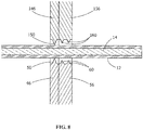
- FIGS. 1 through 7 only one fixed clenching member 56 is shown. However, as shown in FIG. 8 , more than one fixed clenching member 56 may be provided, thereby providing a higher gripping action.
- Support edges 66 are located on either side of cutting blade 46 and clenching member 58.
- the support edges 66 form a portions of an insulation receiving slot.
- the insulation receiving slot is configured to be slightly larger than the maximum diameter of the wire to be stripped.
- the movable blade assembly 42 has a movable second cutting blade 146.
- incline surfaces 150 formed on the movable cutting blade 146 creates a beveled cutting edge.
- Semicircular notches or slots 152 are formed in the inclined surfaces 150 of the movable cutting blade 146 and as is conventional, each of these notches may be of a similar diameter or may be of a different diameter, with each adapted to cut the insulation 12 from conductor wires 14 of a selected size.
- the movable blade assembly 42 also has a movable second clenching member 156.
- the movable second cutting blade 146 and the movable second clenching blade 156 are joined together using known methods, such as, but not limited to, welding or soldering.
- movable clenching member 156 is positioned adjacent movable cutting blade 146.
- other configurations of the second cutting blade 146 and the second clenching member 156 are envisioned without departing from the scope of the invention.
- the second cutting blade 146 and the second clenching member 156 may be formed as a single piece which is positioned in a pocket provided in the movable blade assembly.
- An incline surface 160 ( FIG. 4 ) formed on the movable clenching member 156 creates a beveled clenching blade or edge.
- Semicircular notches or slots 162 are formed in the inclined surface 160 of the movable clenching member 156. Each of these notches may be of a similar diameter or may be of a different diameter, with each adapted to engage, i.e. pierce, clench or grasp, the insulation 12 of conductor wires 14 of a selected size.
- the slots 162 are provided in alignment with respective slots 152.
- slots 162 have larger diameters than respective slots 152, thereby allowing the movable cutting blades 146 to cut essentially through the insulation 12 of the wire 14, while allowing the movable clenching member 156 to pierce the outer surface of the insulation 12 without cutting through the entire layer of insulation 12, as will be more fully described.
- the movable clenching member 156 in the exemplary embodiment shows an inclined surface 160 to form a clenching blade
- the surface 160 may be relatively flat with a soft high friction material, such as, but not limited to, chamois. This would allow the movable clenching member to clench the insulation 12 over a wide surface area without compressing the insulation 12.
- FIGS. 1 through 7 only one movable clenching member 156 is shown. However, as shown in FIG. 8 , more than one movable clenching member 156 may be provided, thereby providing a higher gripping action.
- Support edges 166 are located on either side of cutting blade 146 and clenching member 158.
- the support edges 166 cooperate with the support edges 66 to form insulation receiving slots.
- each insulation receiving slot is configured to be slightly larger than the maximum diameter of the wire to be stripped.
- the exemplary embodiment of the cutting blade assembly 20 is shown with blades positioned on members which are welded or soldered together, other configurations of the cutting blade assembly 20 can be used without departing from the scope of the invention.
- the cutting blade and the clenching member may be separate pieces which are inserted into pockets of the blade assembly.
- the cutting blade, the clenching member and the blade assembly may all be manufactured from one piece.
- a clenching member 56 is provided on the fixed blade assembly 40 and a clenching member 156 is provided on the movable blade assembly 42.
- different types of clenching members may be provided on the fixed blade assembly 40 and the movable blade assembly 42.
- a blade type clenching member may be provided on the fixed blade assembly 40 while a high friction clenching member may be provided on the movable blade assembly 42.
- each clenching member 56, 156 may be comprised of multiple projections formed by multiple inclined surfaces periodically spaced about the circumference of the notches. Other configurations are also possible without departing from the scope of the invention.
- the inclined surface 60, 160 may be aligned essentially perpendicular to the longitudinal axis of the wire 14, as shown, or may be positioned at other angles relative to the longitudinal axis of the wire 14.
- first blade assembly 40 is fixed and the second blade assembly 42 is movable.
- first blade assembly 40 may be movable and the second blade assembly 42 may be fixed.
- first blade assembly 40 and the second blade assembly 42 may both be movable.
- the wire 14 is positioned between the fixed blade assembly 40 and the movable blade assembly 42.
- the wire 14 is positioned in alignment with the respective notches which correspond to the diameter of the wire.
- the cutting blades 46, 146 extend from the respective support edges 66, 166 a further distance than the clenching members 56,156.
- the movable blade assembly 42 is then moved to the position shown in FIG. 6 .
- the fixed cutting blade 46 and the movable cutting blade 146 initially engage the insulation 12 of the wire 14.
- the fixed cutting blade 46 and the movable cutting blade 146 pierce the insulation 12 of the wire 14, cutting the insulation 12 as is known.
- the use and operation of the fixed cutting blade 46 and the movable cutting blade 146 is known in the industry.
- the fixed clenching member 56 and the movable clenching member 156 engage the insulation 12 of the wire 14.
- the fixed clenching member 56 and the movable clenching member 156 pierce the insulation 12 of the wire 14.
- the wire receiving slot is formed by the support edges 66, 166.
- the cutting blades 46, 146 have a smaller diameter than the support edges 66, 166, the cutting blades 46, 146 extend into the insulation receiving slot.
- the clenching members 56, 156 have a smaller diameter than the support edges 66, 166, the clenching members 56, 156 also extend into the insulation receiving slot.
- the clenching members 56, 156 have a larger diameter than the cutting blades 46, 146, the clenching members 56, 156 do not extend into the insulation receiving slot, or the insulation 12 of the wire 14, as far as the cutting blades 46, 146.
- the cutting blades 46, 146 have essentially cut through the insulation 12 without damaging or engaging the conductors of the wire 14. However, due to tolerance variations in the tool and the wire 14, it is often the case that the insulation 12 is not fully cut-through.
- the blade of the clenching members 56, 156 pierce the insulation 12 of the wire 14. In this position, the support edges 66, 166 provide support to the insulation 12 of the wire 14.
- the tool 10 is moved in the direction indicated by arrow 190 shown in FIG. 7 to remove the slug 19 of the insulation 12 from the wire 14.
- the clenching members 56, 156 are in engagement with the insulation of the slug 19. Consequently, as the movable blade assembly 42 and the fixed blade assembly 40 are moved in the direction of arrow 190, the clenching members 56, 156 engage the slug 19 and provide an additional force to the slug 19 in the direction of arrow 190. This additional pulling force moves the slug 19 away from the remaining wire 14.
- the increased pulling force supplied by the clenching members 56, 156 is particularly advantageous when the cutting blades 46, 146 have not fully cut-through the insulation 12.
- the additional force supplied by the clenching members 56, 156 allows any portion of the insulation 12 which has not be cut to be torn away.
- This controlled pulling force supplied by the clenching members 56, 156 provides for the type of clean insulation stripping action required to properly remove the slug 19 from the wire 14.
Landscapes
- Removal Of Insulation Or Armoring From Wires Or Cables (AREA)
- Knives (AREA)
Description
- The present invention is directed to stripping blades for stripping insulation material from an insulated wire. In particular, the invention is directed to stripping blades which provide an additional pulling force for removal of the stripped insulation material.
- When stripping the insulation or insulator of an electric wire, a wire stripper may be used. A conventional wire stripper includes blades which may be pivoted together and two jaws respectively formed integral with the blades at one end for acting against each other to strip the insulator of the electric wire. When the jaws are squeezed toward each other and against the electric wire, the insulator of the electric wire is cut by the cutting edge at each jaw, and then the wire stripper tool is pulled outwards from the electric wire, enabling the cut piece of insulator to be removed from the electric wire. However, when pulling the tool outwards from the electric wire, the blades tend to be biased, which may result in damage to the conductor of the electric wire.
- In order to prevent damage to the conductor of the wire, various wire stripper devices have been developed. One such device is shown in
U.S. Patent Number 6,089,125 . In this device, the wire stripper includes two pressure bars each having a fixed end pivoted to each other and a free end. Two wire stripping cutter assemblies are symmetrically provided at the free ends of the pressure bars for stripping the insulator of a two-line electric wire. An elongated cutter blade is fastened to one pressure bar and moved to act V-notches at the other pressure bar for stripping the insulator of electric wires of different diameters. The wire stripping cutter assemblies each have two symmetrical pairs of movable wire clamping plates respectively supported on a respective spring element, and forced by the respective spring element for holding down a two-line electric wire in position for stripping positively. This keeps the electric wire maintained perpendicular to the cutter blades, enabling the insulator of the electric wire to be positively stripped. - Another device which has the object of removing the insulation form an electrical wire or conductor is shown in
U.S. Patent Number 6,439,084 . A laminated blade assembly includes a stationary blade and a pair of insulation supports and a movable blade and a pair of insulation supports with each blade sandwiched between a pair of supports. Semi-circular grooves formed in the insulation supports and smaller semi-circular grooves formed in blades in alignment with the insulation support grooves creating circular grooves to support and cut the insulation when the stationary and movable blades come together. The support semi-circular grooves of one of the stationary and movable insulation supports are located with their peripheries tangent to a straight line which is not parallel to the center lines of the blade semi-circular grooves. Accordingly, the wire and its insulation will not be bent during severing and insulation removal thus providing a clean cut. - However, while these prior art devices help to support the insulation and the conductor, the problem to be solved is that the removal of the insulation is not always clean and with no damage to the conductor. It would, therefore, be advantageous to provide a stripping mechanism which has an added pulling force to properly remove the insulation, such that the stripped wire meets industry standards, such as, but not limited to, that in SAE AS5457, entitled Aerospace Standard for Hand-Held Wire Stripper Tools.
-
US 2005/0028373 , on which the preamble of claim 1 is based, discloses an insulation stripping assembly for stripping insulation from a conductor. The insulation stripping assembly has a fixed blade holder assembly with a fixed cutting blade between insulation support plates, and a movable blade holder assembly with a movable cutting blade between insulation support plates. During a cutting operation, the fixed and movable cutting blades cut through the insulation whilst the insulation support plates hold the conductor. - The solution is provided by an insulation stripping assembly for stripping insulation from a conductor, the insulation stripping assembly comprising: a first blade assembly, the first blade assembly having a first cutting blade; a second blade assembly, the second blade assembly having a second cutting blade; and a clenching member provided on at least one of the first blade assembly and the second blade assembly, the clenching member being spaced from the first cutting blade and the second cutting blade; wherein the first and second cutting blades essentially cut through the insulation and the clenching member engages the insulation to provide increased pulling force to remove the cut insulation from the conductor, characterized in that the clenching member is a blade which pierces the insulation.
- In an exemplary embodiment, the insulation stripping assembly includes a first, fixed blade assembly and a second, movable blade assembly. Clenching members are provided in the fixed blade assembly and the movable blade assembly. The clenching members are spaced from the first cutting blade and the second cutting blade. The clenching members engage the insulation to provide increased pulling force to remove the cut insulation from the conductor.
- In another exemplary embodiment, the first blade assembly of the insulation stripping assembly has a first clenching member spaced from the first cutting blade and the second blade assembly has a second clenching member spaced from the first cutting blade. An insulation receiving slot for positioning the insulation therein is also provided. The first clenching member extends into the insulation receiving slot a distance less than the first cutting blade and the second clenching member extends into the insulation receiving slot a distance less than the second cutting blade. The first and second clenching members engage the insulation to provide increased pulling force to remove the cut insulation from the conductor.
- In another exemplary embodiment, the first blade assembly of the insulation stripping assembly has a first clenching blade spaced from the first cutting blade, and the second blade assembly has a second clenching blade spaced from the first cutting blade. An insulation receiving slot for positioning the insulation therein is also provided. The first clenching blade extends into the insulation receiving slot a distance less than the first cutting blade and the second clenching blade extends into the insulation receiving slot a distance less than the second cutting blade. The first and second clenching blades engage the insulation to provide increased pulling force to remove the cut insulation from the conductor.
- The invention will now be described by way of example with reference to the accompanying drawings in which:
-
FIG. 1 is a perspective view of an exemplary cutting blade assembly of the present invention. -
FIG. 2 is a top perspective view of a first, fixed blade assembly of the exemplary cutting blade assembly ofFIG. 1 . -
FIG. 3 is a bottom perspective view of a second, movable blade assembly of the exemplary cutting blade assembly ofFIG. 1 . -
FIG. 4 is a cross-sectional view of the exemplary cutting blade assembly showing the first blade assembly and the second blade assembly in an open position, with a wire positioned therebetween. -
FIG. 5 is a cross-sectional view of the exemplary cutting blade assembly showing the first blade assembly and the second blade assembly in a partially closed position. -
FIG. 6 is a cross-sectional view of the exemplary cutting blade assembly showing the first blade assembly and the second blade assembly in a closed position, with cutting blades cutting essentially through the insulation of the wire and the clenching member piercing the insulation. -
FIG. 7 is a cross-sectional view of the exemplary cutting blade assembly showing the first blade assembly and the second blade assembly in a closed position and the cutting blade assembly being moved relative wire to remove the insulation therefrom. -
FIG. 8 is a cross-sectional view of a first exemplary alternate embodiment showing a plurality of clenching members on each blade assembly. -
FIG. 9 is a cross-sectional view of a second exemplary alternate embodiment showing alternate clenching members on each blade assembly. - The present invention will be described more fully hereinafter with reference to the accompanying drawings, in which illustrative embodiments of the invention are shown. In the drawings, the relative sizes of regions or features may be exaggerated for clarity.
- It will be understood that spatially relative terms, such as "top", "upper", "lower" and the like, may be used herein for ease of description to describe one element's or feature's relationship to another element(s) or feature(s) as illustrated in the figures. It will be understood that the spatially relative terms are intended to encompass different orientations of the device in use or operation in addition to the orientation depicted in the figures. For example, if the device in the figures is turned over, elements described as "over" other elements or features would then be oriented "under" the other elements or features. Thus, the exemplary term "over" can encompass both an orientation of over and under. The device may be otherwise oriented (rotated 90 degrees or at other orientations) and the spatially relative descriptors used herein interpreted accordingly.
- The cutting blade or
insulation stripping assembly 20, an exemplary embodiment of which is shown inFIG. 1 , is used forstripping insulation 12 from conductor wires 14 (as is shown inFIGS. 4 through 9 ). Blade assemblies of this type can be used in hand tools or other devices which are used to cut the insulation and remove the cut sleeve of insulation from a conductor wire. Such hand tools and other devices are generally known in the industry. - Referring to
FIG. 1 , the exemplarycutting blade assembly 20 is shown in an open position before placement of the insulated wires for cutting. Theblade assembly 20 includes a fixed or stationaryfirst blade assembly 40 and a movablesecond blade assembly 42 with afoot 44 formed integrally with themovable blade assembly 42. Thefoot 44 connects to a link (not shown) which is connected to a handle of a hand tool or other device in which theblade assembly 20 is used. - As best shown in
FIG. 2 , thefixed blade assembly 40 has a fixed or stationaryfirst cutting blade 46. Incline surfaces 50 (FIG. 4 ) formed on the fixedcutting blade 46 create a beveled cutting edge. Semicircular notches orslots 52 are formed in theinclined surfaces 50 of thecutting blade 46 and as is conventional, each of these notches may be of the same diameter or may be of a different diameter, with each adapted to cut theinsulation 12 fromconductor wires 14 of a selected size. - The
fixed blade assembly 40 also has a fixed or stationaryfirst clenching member 56. Thefirst cutting blade 46 and thefirst clenching member 56 are joined together using known methods, such as, but not limited to, welding or soldering. In the exemplary embodiment, fixedclenching member 56 is positioned proximate fixedcutting blade 46. However, other configurations of thefirst cutting blade 46 and the first clenchingmember 56 are envisioned without departing from the scope of the invention. In one such alternate embodiment, thefirst cutting blade 46 and the first clenchingmember 56 may be formed as a single piece which is positioned in a pocket provided in the fixed blade assembly. - An incline surface 60 (
FIG. 4 ) formed on the fixed clenchingmember 56 creates a beveled clenching blade or edge. Semicircular notches orslots 62 are formed in theinclined surface 60 of the clenchingmember 56. Each of these notches may be of a similar diameter or may be of a different diameter, with each adapted to engage, i.e. pierce, clench or grasp, theinsulation 12 ofconductor wires 14 of a selected size. Theslots 62 are provided in alignment withrespective slots 52. However,slots 62 have larger diameters thanrespective slots 52, thereby allowing the fixedcutting blades 46 to cut essentially through theinsulation 12 of thewire 14, while allowing the fixed clenchingmember 56 to pierce the outer surface of theinsulation 12 without cutting through the entire layer ofinsulation 12, as will be more fully described with reference toFIGS. 4 through 7 . - While the fixed clenching
member 56 in the exemplary embodiment shows aninclined surface 60 to form a clenching blade, other configurations may be used without departing from the scope of the invention. As shown inFIG. 9 , thesurface 60 may be relatively flat with a soft high friction material, such as, but not limited to, chamois. This would allow the fixed clenching member to clench theinsulation 12 over a wide surface area without compressing theinsulation 12. - In the exemplary embodiment shown in
FIGS. 1 through 7 , only one fixed clenchingmember 56 is shown. However, as shown inFIG. 8 , more than one fixed clenchingmember 56 may be provided, thereby providing a higher gripping action. - Support edges 66 are located on either side of cutting
blade 46 and clenching member 58. The support edges 66 form a portions of an insulation receiving slot. In general, the insulation receiving slot is configured to be slightly larger than the maximum diameter of the wire to be stripped. - Referring to
FIG. 3 , themovable blade assembly 42 has a movablesecond cutting blade 146. As best shown inFIG. 4 , incline surfaces 150 formed on themovable cutting blade 146 creates a beveled cutting edge. Semicircular notches orslots 152 are formed in theinclined surfaces 150 of themovable cutting blade 146 and as is conventional, each of these notches may be of a similar diameter or may be of a different diameter, with each adapted to cut theinsulation 12 fromconductor wires 14 of a selected size. - The
movable blade assembly 42 also has a movablesecond clenching member 156. The movablesecond cutting blade 146 and the movablesecond clenching blade 156 are joined together using known methods, such as, but not limited to, welding or soldering. In the exemplary embodiment shown,movable clenching member 156 is positioned adjacentmovable cutting blade 146. However, other configurations of thesecond cutting blade 146 and thesecond clenching member 156 are envisioned without departing from the scope of the invention. In one such alternate embodiment, thesecond cutting blade 146 and thesecond clenching member 156 may be formed as a single piece which is positioned in a pocket provided in the movable blade assembly. - An incline surface 160 (
FIG. 4 ) formed on themovable clenching member 156 creates a beveled clenching blade or edge. Semicircular notches orslots 162 are formed in theinclined surface 160 of themovable clenching member 156. Each of these notches may be of a similar diameter or may be of a different diameter, with each adapted to engage, i.e. pierce, clench or grasp, theinsulation 12 ofconductor wires 14 of a selected size. Theslots 162 are provided in alignment withrespective slots 152. However,slots 162 have larger diameters thanrespective slots 152, thereby allowing themovable cutting blades 146 to cut essentially through theinsulation 12 of thewire 14, while allowing themovable clenching member 156 to pierce the outer surface of theinsulation 12 without cutting through the entire layer ofinsulation 12, as will be more fully described. - While the
movable clenching member 156 in the exemplary embodiment shows aninclined surface 160 to form a clenching blade, other configurations may be used without departing from the scope of the invention. As shown inFIG. 9 , thesurface 160 may be relatively flat with a soft high friction material, such as, but not limited to, chamois. This would allow the movable clenching member to clench theinsulation 12 over a wide surface area without compressing theinsulation 12. - In the exemplary embodiment shown in
FIGS. 1 through 7 , only onemovable clenching member 156 is shown. However, as shown inFIG. 8 , more than onemovable clenching member 156 may be provided, thereby providing a higher gripping action. - Support edges 166 are located on either side of cutting
blade 146 and clenching member 158. The support edges 166 cooperate with the support edges 66 to form insulation receiving slots. In general, each insulation receiving slot is configured to be slightly larger than the maximum diameter of the wire to be stripped. - While the exemplary embodiment of the
cutting blade assembly 20 is shown with blades positioned on members which are welded or soldered together, other configurations of thecutting blade assembly 20 can be used without departing from the scope of the invention. As a first alternate example, the cutting blade and the clenching member may be separate pieces which are inserted into pockets of the blade assembly. As a second alternate embodiment, the cutting blade, the clenching member and the blade assembly may all be manufactured from one piece. - In the exemplary embodiment described, a clenching
member 56 is provided on the fixedblade assembly 40 and a clenchingmember 156 is provided on themovable blade assembly 42. However, different types of clenching members may be provided on the fixedblade assembly 40 and themovable blade assembly 42. As an example, a blade type clenching member may be provided on the fixedblade assembly 40 while a high friction clenching member may be provided on themovable blade assembly 42. - While the clenching
member 56 and the clenchingmember 156 are shown with one projection formed by theinclined surfaces member inclined surface wire 14, as shown, or may be positioned at other angles relative to the longitudinal axis of thewire 14. - In the exemplary embodiment shown, the
first blade assembly 40 is fixed and thesecond blade assembly 42 is movable. However, in one alternate exemplary embodiment, thefirst blade assembly 40 may be movable and thesecond blade assembly 42 may be fixed. In another alternate exemplary embodiment, thefirst blade assembly 40 and thesecond blade assembly 42 may both be movable. - Referring to
FIGS. 4 through 7 , the operation of thecutting blade assembly 20 will now be described. Initially, as shown inFIG. 4 , thewire 14 is positioned between the fixedblade assembly 40 and themovable blade assembly 42. Thewire 14 is positioned in alignment with the respective notches which correspond to the diameter of the wire. As is shown, and as was previously described, thecutting blades - The
movable blade assembly 42 is then moved to the position shown inFIG. 6 . In this position, the fixedcutting blade 46 and themovable cutting blade 146 initially engage theinsulation 12 of thewire 14. As the movement of themovable blade assembly 42 toward the fixedblade assembly 40 continues, the fixedcutting blade 46 and themovable cutting blade 146 pierce theinsulation 12 of thewire 14, cutting theinsulation 12 as is known. The use and operation of the fixedcutting blade 46 and themovable cutting blade 146 is known in the industry. - As the movement of the
movable blade assembly 42 toward the fixedblade assembly 40 continues, the fixed clenchingmember 56 and themovable clenching member 156 engage theinsulation 12 of thewire 14. In the exemplary embodiment shown, the fixed clenchingmember 56 and themovable clenching member 156 pierce theinsulation 12 of thewire 14. - Movement of the
movable blade assembly 42 toward the fixedblade assembly 40 continues until themovable blade assembly 42 engages the fixedblade assembly 40 which defines a closed position, as shown inFIG. 6 . In this position, the wire receiving slot is formed by the support edges 66, 166. As thecutting blades cutting blades members members members cutting blades members insulation 12 of thewire 14, as far as thecutting blades - In the position shown in
FIG. 6 , thecutting blades insulation 12 without damaging or engaging the conductors of thewire 14. However, due to tolerance variations in the tool and thewire 14, it is often the case that theinsulation 12 is not fully cut-through. In the closed position, the blade of the clenchingmembers insulation 12 of thewire 14. In this position, the support edges 66, 166 provide support to theinsulation 12 of thewire 14. - With the
movable blade assembly 42 and the fixedblade assembly 40 in the closed position, the tool 10 is moved in the direction indicated byarrow 190 shown inFIG. 7 to remove theslug 19 of theinsulation 12 from thewire 14. As this occurs, the clenchingmembers slug 19. Consequently, as themovable blade assembly 42 and the fixedblade assembly 40 are moved in the direction ofarrow 190, the clenchingmembers slug 19 and provide an additional force to theslug 19 in the direction ofarrow 190. This additional pulling force moves theslug 19 away from the remainingwire 14. While this facilitates the removal of theslug 19 in general, the increased pulling force supplied by the clenchingmembers cutting blades insulation 12. The additional force supplied by the clenchingmembers insulation 12 which has not be cut to be torn away. This controlled pulling force supplied by the clenchingmembers slug 19 from thewire 14.
Claims (9)
- An insulation stripping assembly (20) for stripping insulation (12) from a conductor (14), the insulation stripping assembly (20) comprising: a first blade assembly (40), the first blade assembly (40) having a first cutting blade (46); a second blade assembly (42), the second blade assembly (42) having a second cutting blade (146); and a clenching member (56) provided on at least one of the first blade assembly (40) and the second blade assembly (42), the clenching member (56) being spaced from the first cutting blade (46) and the second cutting blade (146); wherein the first and second cutting blades (46, 146) essentially cut through the insulation (12) and the clenching member (56) engages the insulation (12) to provide increased pulling force to remove the cut insulation from the conductor (14), characterized in thatthe clenching member (56) is a blade which pierces the insulation (12).
- The insulation stripping assembly as recited in claim 1, wherein the clenching member (56) has a flat surface (60) with a high friction material provided thereon.
- The insulation stripping assembly as recited in claim 1, wherein the first blade assembly (40) is fixed, the clenching member (56) being positioned on the first blade assembly (40).
- The insulation stripping assembly as recited in claim 1, wherein the second blade assembly (42) is movable, the clenching member (156) being positioned on the second blade assembly (42).
- The insulation stripping assembly as recited in claim 1, wherein a first clenching member (56) is positioned on the first blade assembly (40), the first clenching member (56) extending into an insulation receiving slot (66, 166) a distance less than the first cutting blade (46).
- The insulation stripping assembly as recited in claim 5, wherein a second clenching member (156) is positioned on the second blade assembly (42), the second clenching member (156) extending into the insulation receiving slot (66, 166) a distance less than the second cutting blade (146).
- The insulation stripping assembly as recited in claim 6, wherein support surfaces (66, 166) are provided proximate the first cutting blade (46) and the first clenching member (56) and proximate the second cutting blade (146) and the second clenching member (156), the support surfaces define the insulation receiving slot.
- The insulation stripping assembly as recited in claim 1, wherein a plurality of clenching members (56, 156) are provided.
- The insulation stripping assembly as recited in claim 6, wherein the first and second clenching members (56, 156) are each comprised of a plurality of inclined surfaces (60, 160) which are periodically spaced about the circumference of the insulation receiving slots (66, 166).
Applications Claiming Priority (2)
| Application Number | Priority Date | Filing Date | Title |
|---|---|---|---|
| US13/654,508 US9281668B2 (en) | 2012-10-18 | 2012-10-18 | Stripping blades for cutting insulation |
| PCT/US2013/065338 WO2014062864A1 (en) | 2012-10-18 | 2013-10-17 | Stripping blades for cutting insulation |
Publications (2)
| Publication Number | Publication Date |
|---|---|
| EP2909903A1 EP2909903A1 (en) | 2015-08-26 |
| EP2909903B1 true EP2909903B1 (en) | 2017-03-15 |
Family
ID=49684064
Family Applications (1)
| Application Number | Title | Priority Date | Filing Date |
|---|---|---|---|
| EP13799134.5A Not-in-force EP2909903B1 (en) | 2012-10-18 | 2013-10-17 | Stripping blades for cutting insulation |
Country Status (4)
| Country | Link |
|---|---|
| US (1) | US9281668B2 (en) |
| EP (1) | EP2909903B1 (en) |
| CN (1) | CN104813551B (en) |
| WO (1) | WO2014062864A1 (en) |
Families Citing this family (2)
| Publication number | Priority date | Publication date | Assignee | Title |
|---|---|---|---|---|
| CN106848945A (en) * | 2017-04-24 | 2017-06-13 | 国网山东省电力公司青州市供电公司 | Wiring line connector |
| CN107221890A (en) * | 2017-07-15 | 2017-09-29 | 南通明光电线有限公司 | Set refers to formula wire-insulation stripper |
Family Cites Families (14)
| Publication number | Priority date | Publication date | Assignee | Title |
|---|---|---|---|---|
| US2179581A (en) * | 1937-06-21 | 1939-11-14 | Robert J Montgomery | Wire stripper hand tool |
| FR1317615A (en) * | 1961-03-14 | 1963-05-08 | ||
| US3735649A (en) * | 1970-05-27 | 1973-05-29 | J Staggs | Parting blade wire stripper |
| US4246808A (en) | 1979-03-09 | 1981-01-27 | Ideal Industries, Inc. | Precision small wire stripper and blade structure |
| US4350061A (en) | 1979-11-01 | 1982-09-21 | Ideal Industries, Inc. | Wire stripping mechanism |
| US4485696A (en) * | 1980-03-17 | 1984-12-04 | Zdzislaw Bieganski | Apparatus for wire stripping |
| US5269206A (en) * | 1991-02-28 | 1993-12-14 | Amp Incorporated | Cable stripping apparatus |
| CN2112898U (en) * | 1991-12-28 | 1992-08-12 | 孙殿成 | Wire strip pliers |
| US6089125A (en) | 1999-08-27 | 2000-07-18 | Cheng; Yin-Ho | Combination wire stripper |
| US6439085B1 (en) | 2000-10-24 | 2002-08-27 | G. Lyle Habermehl | Double arm pawl for autofeed screwdriver |
| US6439084B1 (en) | 2001-05-07 | 2002-08-27 | Ideal Industries, Inc. | Laminated blade assembly for cutting insulation |
| JP4535219B2 (en) * | 2001-06-12 | 2010-09-01 | 住友電気工業株式会社 | Optical fiber coating removal device |
| US7000322B2 (en) | 2003-08-08 | 2006-02-21 | Ideal Industries, Inc. | Blade assembly |
| DK2056416T3 (en) * | 2007-11-02 | 2016-11-28 | Weidmueller Interface Gmbh & Co Kg | Stripper |
-
2012
- 2012-10-18 US US13/654,508 patent/US9281668B2/en not_active Expired - Fee Related
-
2013
- 2013-10-17 EP EP13799134.5A patent/EP2909903B1/en not_active Not-in-force
- 2013-10-17 WO PCT/US2013/065338 patent/WO2014062864A1/en active Application Filing
- 2013-10-17 CN CN201380059484.0A patent/CN104813551B/en not_active Expired - Fee Related
Non-Patent Citations (1)
| Title |
|---|
| None * |
Also Published As
| Publication number | Publication date |
|---|---|
| EP2909903A1 (en) | 2015-08-26 |
| CN104813551B (en) | 2017-08-15 |
| US20140109410A1 (en) | 2014-04-24 |
| WO2014062864A1 (en) | 2014-04-24 |
| CN104813551A (en) | 2015-07-29 |
| US9281668B2 (en) | 2016-03-08 |
Similar Documents
| Publication | Publication Date | Title |
|---|---|---|
| US4607544A (en) | Tool for cutting, stripping and connecting electric wire | |
| US7637769B2 (en) | Cap, a termination assembly and a housing assembly for a modular telecom connection jack | |
| US20180159249A1 (en) | Metal clip for electrically connecting a conductive wire to a metal element | |
| US8863620B2 (en) | Hand tool with stripping and shearing functions | |
| JP2008235130A (en) | Terminal connection structure of electric wire, and its terminal connection method | |
| EP2260548A2 (en) | Termination tool with corresponding male and female connectors | |
| EP2079137A1 (en) | Wire stripping knife | |
| CA2885215A1 (en) | Split bolt electrical connector assembly | |
| US20140345061A1 (en) | High voltage cable preparation tool | |
| JP3176081U (en) | Abbreviated scissors-type manual instrument scale | |
| EP2909903B1 (en) | Stripping blades for cutting insulation | |
| US9472869B2 (en) | Insulation displacement wire connectors | |
| JP5830355B2 (en) | Electric wire processing apparatus and electric wire processing method | |
| US20180226776A1 (en) | Cable Stripping Tool | |
| US20150188272A1 (en) | Hand tool for stripping wire and crimping wire connectors | |
| US7802496B2 (en) | Stripper for round sheathed cable | |
| US8898911B2 (en) | Tool accommodating replaceable blade | |
| JP2011514951A (en) | Cable ties | |
| KR101063781B1 (en) | Apparatus for combining a terminal to a cable | |
| US3355803A (en) | Tweezer-like tool for longitudinally slitting the web connecting a joined conductor-pair | |
| US7000322B2 (en) | Blade assembly | |
| US10992118B1 (en) | Wire stripping tool | |
| US20070261250A1 (en) | Combination wire stamper, stripper and labeler | |
| US1196322A (en) | Wire-stripping device. | |
| WO1980001339A1 (en) | Improved electrical coupling devices |
Legal Events
| Date | Code | Title | Description |
|---|---|---|---|
| PUAI | Public reference made under article 153(3) epc to a published international application that has entered the european phase |
Free format text: ORIGINAL CODE: 0009012 |
|
| 17P | Request for examination filed |
Effective date: 20150428 |
|
| AK | Designated contracting states |
Kind code of ref document: A1 Designated state(s): AL AT BE BG CH CY CZ DE DK EE ES FI FR GB GR HR HU IE IS IT LI LT LU LV MC MK MT NL NO PL PT RO RS SE SI SK SM TR |
|
| AX | Request for extension of the european patent |
Extension state: BA ME |
|
| DAX | Request for extension of the european patent (deleted) | ||
| GRAP | Despatch of communication of intention to grant a patent |
Free format text: ORIGINAL CODE: EPIDOSNIGR1 |
|
| INTG | Intention to grant announced |
Effective date: 20160908 |
|
| GRAJ | Information related to disapproval of communication of intention to grant by the applicant or resumption of examination proceedings by the epo deleted |
Free format text: ORIGINAL CODE: EPIDOSDIGR1 |
|
| GRAR | Information related to intention to grant a patent recorded |
Free format text: ORIGINAL CODE: EPIDOSNIGR71 |
|
| GRAS | Grant fee paid |
Free format text: ORIGINAL CODE: EPIDOSNIGR3 |
|
| GRAA | (expected) grant |
Free format text: ORIGINAL CODE: 0009210 |
|
| RAP1 | Party data changed (applicant data changed or rights of an application transferred) |
Owner name: TE CONNECTIVITY CORPORATION |
|
| INTC | Intention to grant announced (deleted) | ||
| INTG | Intention to grant announced |
Effective date: 20170201 |
|
| AK | Designated contracting states |
Kind code of ref document: B1 Designated state(s): AL AT BE BG CH CY CZ DE DK EE ES FI FR GB GR HR HU IE IS IT LI LT LU LV MC MK MT NL NO PL PT RO RS SE SI SK SM TR |
|
| REG | Reference to a national code |
Ref country code: CH Ref legal event code: EP Ref country code: GB Ref legal event code: FG4D |
|
| REG | Reference to a national code |
Ref country code: IE Ref legal event code: FG4D |
|
| REG | Reference to a national code |
Ref country code: AT Ref legal event code: REF Ref document number: 876451 Country of ref document: AT Kind code of ref document: T Effective date: 20170415 |
|
| REG | Reference to a national code |
Ref country code: DE Ref legal event code: R096 Ref document number: 602013018663 Country of ref document: DE |
|
| REG | Reference to a national code |
Ref country code: NL Ref legal event code: MP Effective date: 20170315 |
|
| REG | Reference to a national code |
Ref country code: LT Ref legal event code: MG4D |
|
| PG25 | Lapsed in a contracting state [announced via postgrant information from national office to epo] |
Ref country code: NO Free format text: LAPSE BECAUSE OF FAILURE TO SUBMIT A TRANSLATION OF THE DESCRIPTION OR TO PAY THE FEE WITHIN THE PRESCRIBED TIME-LIMIT Effective date: 20170615 Ref country code: GR Free format text: LAPSE BECAUSE OF FAILURE TO SUBMIT A TRANSLATION OF THE DESCRIPTION OR TO PAY THE FEE WITHIN THE PRESCRIBED TIME-LIMIT Effective date: 20170616 Ref country code: FI Free format text: LAPSE BECAUSE OF FAILURE TO SUBMIT A TRANSLATION OF THE DESCRIPTION OR TO PAY THE FEE WITHIN THE PRESCRIBED TIME-LIMIT Effective date: 20170315 Ref country code: LT Free format text: LAPSE BECAUSE OF FAILURE TO SUBMIT A TRANSLATION OF THE DESCRIPTION OR TO PAY THE FEE WITHIN THE PRESCRIBED TIME-LIMIT Effective date: 20170315 Ref country code: HR Free format text: LAPSE BECAUSE OF FAILURE TO SUBMIT A TRANSLATION OF THE DESCRIPTION OR TO PAY THE FEE WITHIN THE PRESCRIBED TIME-LIMIT Effective date: 20170315 |
|
| REG | Reference to a national code |
Ref country code: AT Ref legal event code: MK05 Ref document number: 876451 Country of ref document: AT Kind code of ref document: T Effective date: 20170315 |
|
| PG25 | Lapsed in a contracting state [announced via postgrant information from national office to epo] |
Ref country code: LV Free format text: LAPSE BECAUSE OF FAILURE TO SUBMIT A TRANSLATION OF THE DESCRIPTION OR TO PAY THE FEE WITHIN THE PRESCRIBED TIME-LIMIT Effective date: 20170315 Ref country code: SE Free format text: LAPSE BECAUSE OF FAILURE TO SUBMIT A TRANSLATION OF THE DESCRIPTION OR TO PAY THE FEE WITHIN THE PRESCRIBED TIME-LIMIT Effective date: 20170315 Ref country code: RS Free format text: LAPSE BECAUSE OF FAILURE TO SUBMIT A TRANSLATION OF THE DESCRIPTION OR TO PAY THE FEE WITHIN THE PRESCRIBED TIME-LIMIT Effective date: 20170315 Ref country code: BG Free format text: LAPSE BECAUSE OF FAILURE TO SUBMIT A TRANSLATION OF THE DESCRIPTION OR TO PAY THE FEE WITHIN THE PRESCRIBED TIME-LIMIT Effective date: 20170615 |
|
| PG25 | Lapsed in a contracting state [announced via postgrant information from national office to epo] |
Ref country code: NL Free format text: LAPSE BECAUSE OF FAILURE TO SUBMIT A TRANSLATION OF THE DESCRIPTION OR TO PAY THE FEE WITHIN THE PRESCRIBED TIME-LIMIT Effective date: 20170315 |
|
| REG | Reference to a national code |
Ref country code: FR Ref legal event code: PLFP Year of fee payment: 5 |
|
| PG25 | Lapsed in a contracting state [announced via postgrant information from national office to epo] |
Ref country code: EE Free format text: LAPSE BECAUSE OF FAILURE TO SUBMIT A TRANSLATION OF THE DESCRIPTION OR TO PAY THE FEE WITHIN THE PRESCRIBED TIME-LIMIT Effective date: 20170315 Ref country code: IT Free format text: LAPSE BECAUSE OF FAILURE TO SUBMIT A TRANSLATION OF THE DESCRIPTION OR TO PAY THE FEE WITHIN THE PRESCRIBED TIME-LIMIT Effective date: 20170315 Ref country code: SK Free format text: LAPSE BECAUSE OF FAILURE TO SUBMIT A TRANSLATION OF THE DESCRIPTION OR TO PAY THE FEE WITHIN THE PRESCRIBED TIME-LIMIT Effective date: 20170315 Ref country code: AT Free format text: LAPSE BECAUSE OF FAILURE TO SUBMIT A TRANSLATION OF THE DESCRIPTION OR TO PAY THE FEE WITHIN THE PRESCRIBED TIME-LIMIT Effective date: 20170315 Ref country code: RO Free format text: LAPSE BECAUSE OF FAILURE TO SUBMIT A TRANSLATION OF THE DESCRIPTION OR TO PAY THE FEE WITHIN THE PRESCRIBED TIME-LIMIT Effective date: 20170315 Ref country code: ES Free format text: LAPSE BECAUSE OF FAILURE TO SUBMIT A TRANSLATION OF THE DESCRIPTION OR TO PAY THE FEE WITHIN THE PRESCRIBED TIME-LIMIT Effective date: 20170315 Ref country code: CZ Free format text: LAPSE BECAUSE OF FAILURE TO SUBMIT A TRANSLATION OF THE DESCRIPTION OR TO PAY THE FEE WITHIN THE PRESCRIBED TIME-LIMIT Effective date: 20170315 |
|
| PG25 | Lapsed in a contracting state [announced via postgrant information from national office to epo] |
Ref country code: IS Free format text: LAPSE BECAUSE OF FAILURE TO SUBMIT A TRANSLATION OF THE DESCRIPTION OR TO PAY THE FEE WITHIN THE PRESCRIBED TIME-LIMIT Effective date: 20170715 Ref country code: SM Free format text: LAPSE BECAUSE OF FAILURE TO SUBMIT A TRANSLATION OF THE DESCRIPTION OR TO PAY THE FEE WITHIN THE PRESCRIBED TIME-LIMIT Effective date: 20170315 Ref country code: PT Free format text: LAPSE BECAUSE OF FAILURE TO SUBMIT A TRANSLATION OF THE DESCRIPTION OR TO PAY THE FEE WITHIN THE PRESCRIBED TIME-LIMIT Effective date: 20170717 Ref country code: PL Free format text: LAPSE BECAUSE OF FAILURE TO SUBMIT A TRANSLATION OF THE DESCRIPTION OR TO PAY THE FEE WITHIN THE PRESCRIBED TIME-LIMIT Effective date: 20170315 |
|
| REG | Reference to a national code |
Ref country code: DE Ref legal event code: R097 Ref document number: 602013018663 Country of ref document: DE |
|
| PLBE | No opposition filed within time limit |
Free format text: ORIGINAL CODE: 0009261 |
|
| STAA | Information on the status of an ep patent application or granted ep patent |
Free format text: STATUS: NO OPPOSITION FILED WITHIN TIME LIMIT |
|
| PG25 | Lapsed in a contracting state [announced via postgrant information from national office to epo] |
Ref country code: DK Free format text: LAPSE BECAUSE OF FAILURE TO SUBMIT A TRANSLATION OF THE DESCRIPTION OR TO PAY THE FEE WITHIN THE PRESCRIBED TIME-LIMIT Effective date: 20170315 |
|
| 26N | No opposition filed |
Effective date: 20171218 |
|
| PG25 | Lapsed in a contracting state [announced via postgrant information from national office to epo] |
Ref country code: SI Free format text: LAPSE BECAUSE OF FAILURE TO SUBMIT A TRANSLATION OF THE DESCRIPTION OR TO PAY THE FEE WITHIN THE PRESCRIBED TIME-LIMIT Effective date: 20170315 |
|
| PG25 | Lapsed in a contracting state [announced via postgrant information from national office to epo] |
Ref country code: MC Free format text: LAPSE BECAUSE OF FAILURE TO SUBMIT A TRANSLATION OF THE DESCRIPTION OR TO PAY THE FEE WITHIN THE PRESCRIBED TIME-LIMIT Effective date: 20170315 |
|
| REG | Reference to a national code |
Ref country code: CH Ref legal event code: PL |
|
| REG | Reference to a national code |
Ref country code: IE Ref legal event code: MM4A |
|
| PG25 | Lapsed in a contracting state [announced via postgrant information from national office to epo] |
Ref country code: CH Free format text: LAPSE BECAUSE OF NON-PAYMENT OF DUE FEES Effective date: 20171031 Ref country code: LU Free format text: LAPSE BECAUSE OF NON-PAYMENT OF DUE FEES Effective date: 20171017 Ref country code: LI Free format text: LAPSE BECAUSE OF NON-PAYMENT OF DUE FEES Effective date: 20171031 |
|
| REG | Reference to a national code |
Ref country code: BE Ref legal event code: MM Effective date: 20171031 |
|
| PG25 | Lapsed in a contracting state [announced via postgrant information from national office to epo] |
Ref country code: BE Free format text: LAPSE BECAUSE OF NON-PAYMENT OF DUE FEES Effective date: 20171031 |
|
| REG | Reference to a national code |
Ref country code: FR Ref legal event code: PLFP Year of fee payment: 6 |
|
| PG25 | Lapsed in a contracting state [announced via postgrant information from national office to epo] |
Ref country code: MT Free format text: LAPSE BECAUSE OF NON-PAYMENT OF DUE FEES Effective date: 20171017 |
|
| PG25 | Lapsed in a contracting state [announced via postgrant information from national office to epo] |
Ref country code: IE Free format text: LAPSE BECAUSE OF NON-PAYMENT OF DUE FEES Effective date: 20171017 |
|
| PG25 | Lapsed in a contracting state [announced via postgrant information from national office to epo] |
Ref country code: HU Free format text: LAPSE BECAUSE OF FAILURE TO SUBMIT A TRANSLATION OF THE DESCRIPTION OR TO PAY THE FEE WITHIN THE PRESCRIBED TIME-LIMIT; INVALID AB INITIO Effective date: 20131017 |
|
| PG25 | Lapsed in a contracting state [announced via postgrant information from national office to epo] |
Ref country code: CY Free format text: LAPSE BECAUSE OF FAILURE TO SUBMIT A TRANSLATION OF THE DESCRIPTION OR TO PAY THE FEE WITHIN THE PRESCRIBED TIME-LIMIT Effective date: 20170315 |
|
| PG25 | Lapsed in a contracting state [announced via postgrant information from national office to epo] |
Ref country code: MK Free format text: LAPSE BECAUSE OF FAILURE TO SUBMIT A TRANSLATION OF THE DESCRIPTION OR TO PAY THE FEE WITHIN THE PRESCRIBED TIME-LIMIT Effective date: 20170315 |
|
| PG25 | Lapsed in a contracting state [announced via postgrant information from national office to epo] |
Ref country code: TR Free format text: LAPSE BECAUSE OF FAILURE TO SUBMIT A TRANSLATION OF THE DESCRIPTION OR TO PAY THE FEE WITHIN THE PRESCRIBED TIME-LIMIT Effective date: 20170315 |
|
| PG25 | Lapsed in a contracting state [announced via postgrant information from national office to epo] |
Ref country code: AL Free format text: LAPSE BECAUSE OF FAILURE TO SUBMIT A TRANSLATION OF THE DESCRIPTION OR TO PAY THE FEE WITHIN THE PRESCRIBED TIME-LIMIT Effective date: 20170315 |
|
| PGFP | Annual fee paid to national office [announced via postgrant information from national office to epo] |
Ref country code: FR Payment date: 20200914 Year of fee payment: 8 |
|
| PGFP | Annual fee paid to national office [announced via postgrant information from national office to epo] |
Ref country code: DE Payment date: 20201006 Year of fee payment: 8 Ref country code: GB Payment date: 20201007 Year of fee payment: 8 |
|
| REG | Reference to a national code |
Ref country code: DE Ref legal event code: R119 Ref document number: 602013018663 Country of ref document: DE |
|
| GBPC | Gb: european patent ceased through non-payment of renewal fee |
Effective date: 20211017 |
|
| PG25 | Lapsed in a contracting state [announced via postgrant information from national office to epo] |
Ref country code: GB Free format text: LAPSE BECAUSE OF NON-PAYMENT OF DUE FEES Effective date: 20211017 Ref country code: DE Free format text: LAPSE BECAUSE OF NON-PAYMENT OF DUE FEES Effective date: 20220503 |
|
| PG25 | Lapsed in a contracting state [announced via postgrant information from national office to epo] |
Ref country code: FR Free format text: LAPSE BECAUSE OF NON-PAYMENT OF DUE FEES Effective date: 20211031 |