EP2909646B1 - Changing a position determination scheme used by a user equipment during a transition between indoor and outdoor spaces relative to an enclosed environment - Google Patents
Changing a position determination scheme used by a user equipment during a transition between indoor and outdoor spaces relative to an enclosed environment Download PDFInfo
- Publication number
- EP2909646B1 EP2909646B1 EP13789095.0A EP13789095A EP2909646B1 EP 2909646 B1 EP2909646 B1 EP 2909646B1 EP 13789095 A EP13789095 A EP 13789095A EP 2909646 B1 EP2909646 B1 EP 2909646B1
- Authority
- EP
- European Patent Office
- Prior art keywords
- outdoor
- indoor
- positioning scheme
- location tracking
- location
- Prior art date
- Legal status (The legal status is an assumption and is not a legal conclusion. Google has not performed a legal analysis and makes no representation as to the accuracy of the status listed.)
- Active
Links
- 230000007704 transition Effects 0.000 title claims description 121
- 238000000034 method Methods 0.000 claims description 49
- 230000004044 response Effects 0.000 claims description 10
- 230000000977 initiatory effect Effects 0.000 claims description 7
- 238000001514 detection method Methods 0.000 claims 4
- 238000004891 communication Methods 0.000 description 42
- 230000008569 process Effects 0.000 description 23
- 230000006870 function Effects 0.000 description 15
- 230000001413 cellular effect Effects 0.000 description 10
- 238000005259 measurement Methods 0.000 description 8
- 230000009471 action Effects 0.000 description 5
- 230000003287 optical effect Effects 0.000 description 5
- 238000005516 engineering process Methods 0.000 description 4
- 238000012545 processing Methods 0.000 description 4
- 230000005540 biological transmission Effects 0.000 description 3
- 230000003993 interaction Effects 0.000 description 3
- 230000007246 mechanism Effects 0.000 description 3
- 230000008901 benefit Effects 0.000 description 2
- 239000003795 chemical substances by application Substances 0.000 description 2
- 239000000835 fiber Substances 0.000 description 2
- 239000002245 particle Substances 0.000 description 2
- 102100022749 Aminopeptidase N Human genes 0.000 description 1
- 101710099461 Aminopeptidase N Proteins 0.000 description 1
- 241000760358 Enodes Species 0.000 description 1
- 230000010267 cellular communication Effects 0.000 description 1
- 235000019506 cigar Nutrition 0.000 description 1
- 238000004590 computer program Methods 0.000 description 1
- 238000013461 design Methods 0.000 description 1
- 238000011156 evaluation Methods 0.000 description 1
- 238000012986 modification Methods 0.000 description 1
- 230000004048 modification Effects 0.000 description 1
- 238000012544 monitoring process Methods 0.000 description 1
- 230000006855 networking Effects 0.000 description 1
- 238000005192 partition Methods 0.000 description 1
- 230000002093 peripheral effect Effects 0.000 description 1
- 238000012552 review Methods 0.000 description 1
- 230000001953 sensory effect Effects 0.000 description 1
- 230000000391 smoking effect Effects 0.000 description 1
- 238000012546 transfer Methods 0.000 description 1
Images


Classifications
-
- G—PHYSICS
- G01—MEASURING; TESTING
- G01C—MEASURING DISTANCES, LEVELS OR BEARINGS; SURVEYING; NAVIGATION; GYROSCOPIC INSTRUMENTS; PHOTOGRAMMETRY OR VIDEOGRAMMETRY
- G01C21/00—Navigation; Navigational instruments not provided for in groups G01C1/00 - G01C19/00
- G01C21/20—Instruments for performing navigational calculations
- G01C21/206—Instruments for performing navigational calculations specially adapted for indoor navigation
-
- G—PHYSICS
- G01—MEASURING; TESTING
- G01S—RADIO DIRECTION-FINDING; RADIO NAVIGATION; DETERMINING DISTANCE OR VELOCITY BY USE OF RADIO WAVES; LOCATING OR PRESENCE-DETECTING BY USE OF THE REFLECTION OR RERADIATION OF RADIO WAVES; ANALOGOUS ARRANGEMENTS USING OTHER WAVES
- G01S19/00—Satellite radio beacon positioning systems; Determining position, velocity or attitude using signals transmitted by such systems
- G01S19/38—Determining a navigation solution using signals transmitted by a satellite radio beacon positioning system
- G01S19/39—Determining a navigation solution using signals transmitted by a satellite radio beacon positioning system the satellite radio beacon positioning system transmitting time-stamped messages, e.g. GPS [Global Positioning System], GLONASS [Global Orbiting Navigation Satellite System] or GALILEO
- G01S19/42—Determining position
- G01S19/48—Determining position by combining or switching between position solutions derived from the satellite radio beacon positioning system and position solutions derived from a further system
-
- G—PHYSICS
- G01—MEASURING; TESTING
- G01S—RADIO DIRECTION-FINDING; RADIO NAVIGATION; DETERMINING DISTANCE OR VELOCITY BY USE OF RADIO WAVES; LOCATING OR PRESENCE-DETECTING BY USE OF THE REFLECTION OR RERADIATION OF RADIO WAVES; ANALOGOUS ARRANGEMENTS USING OTHER WAVES
- G01S5/00—Position-fixing by co-ordinating two or more direction or position line determinations; Position-fixing by co-ordinating two or more distance determinations
- G01S5/0009—Transmission of position information to remote stations
- G01S5/0045—Transmission from base station to mobile station
-
- G—PHYSICS
- G01—MEASURING; TESTING
- G01S—RADIO DIRECTION-FINDING; RADIO NAVIGATION; DETERMINING DISTANCE OR VELOCITY BY USE OF RADIO WAVES; LOCATING OR PRESENCE-DETECTING BY USE OF THE REFLECTION OR RERADIATION OF RADIO WAVES; ANALOGOUS ARRANGEMENTS USING OTHER WAVES
- G01S5/00—Position-fixing by co-ordinating two or more direction or position line determinations; Position-fixing by co-ordinating two or more distance determinations
- G01S5/01—Determining conditions which influence positioning, e.g. radio environment, state of motion or energy consumption
- G01S5/012—Identifying whether indoors or outdoors
-
- G—PHYSICS
- G01—MEASURING; TESTING
- G01S—RADIO DIRECTION-FINDING; RADIO NAVIGATION; DETERMINING DISTANCE OR VELOCITY BY USE OF RADIO WAVES; LOCATING OR PRESENCE-DETECTING BY USE OF THE REFLECTION OR RERADIATION OF RADIO WAVES; ANALOGOUS ARRANGEMENTS USING OTHER WAVES
- G01S5/00—Position-fixing by co-ordinating two or more direction or position line determinations; Position-fixing by co-ordinating two or more distance determinations
- G01S5/01—Determining conditions which influence positioning, e.g. radio environment, state of motion or energy consumption
- G01S5/014—Identifying transitions between environments
- G01S5/015—Identifying transitions between environments between indoor and outdoor environments
-
- G—PHYSICS
- G01—MEASURING; TESTING
- G01S—RADIO DIRECTION-FINDING; RADIO NAVIGATION; DETERMINING DISTANCE OR VELOCITY BY USE OF RADIO WAVES; LOCATING OR PRESENCE-DETECTING BY USE OF THE REFLECTION OR RERADIATION OF RADIO WAVES; ANALOGOUS ARRANGEMENTS USING OTHER WAVES
- G01S5/00—Position-fixing by co-ordinating two or more direction or position line determinations; Position-fixing by co-ordinating two or more distance determinations
- G01S5/02—Position-fixing by co-ordinating two or more direction or position line determinations; Position-fixing by co-ordinating two or more distance determinations using radio waves
- G01S5/0294—Trajectory determination or predictive filtering, e.g. target tracking or Kalman filtering
-
- Y—GENERAL TAGGING OF NEW TECHNOLOGICAL DEVELOPMENTS; GENERAL TAGGING OF CROSS-SECTIONAL TECHNOLOGIES SPANNING OVER SEVERAL SECTIONS OF THE IPC; TECHNICAL SUBJECTS COVERED BY FORMER USPC CROSS-REFERENCE ART COLLECTIONS [XRACs] AND DIGESTS
- Y02—TECHNOLOGIES OR APPLICATIONS FOR MITIGATION OR ADAPTATION AGAINST CLIMATE CHANGE
- Y02D—CLIMATE CHANGE MITIGATION TECHNOLOGIES IN INFORMATION AND COMMUNICATION TECHNOLOGIES [ICT], I.E. INFORMATION AND COMMUNICATION TECHNOLOGIES AIMING AT THE REDUCTION OF THEIR OWN ENERGY USE
- Y02D30/00—Reducing energy consumption in communication networks
- Y02D30/70—Reducing energy consumption in communication networks in wireless communication networks
Definitions
- Embodiments of the invention relate to changing a position determination scheme used by a user equipment (UE) during a transition between indoor and outdoor spaces relative to an enclosed environment.
- UE user equipment
- client devices e.g., mobile devices such as cell phones
- mobile devices can use satellite positioning systems (SPS) such as the Global Positioning System (GPS), terrestrial cellular stations, a hybrid between GPS and terrestrial cellular, radio frequency (RF) fingerprinting, WiFi positioning, forward link trilateration (FLT), advanced FLT (AFLT), and so on.
- SPS satellite positioning systems
- GPS Global Positioning System
- RF radio frequency
- WiFi positioning Wireless Fidelity
- FLT forward link trilateration
- AFLT advanced FLT
- Certain position determination schemes are more suited to outdoor environments (e.g., SPS, GPS, etc.), while other positioning schemes are more suited to indoor environments (e.g., WiFi positioning, etc.).
- One option is to turn on, for example, both GPS and WiFi position determination schemes at all times so that when the mobile stations transitions between indoor and outdoor spaces, at least one suitable position determination scheme is available.
- the position determination schemes can degrade the battery life of the mobile station.
- Document US 2011/172906 A1 refers to a scheme comprising identifying up to a specified amount of points of interest nearest to an estimated position of a mobile station on a first map, selecting a second map identified by a first location context identifier associated with a first point of interest of the identified points of interest, and determining a route from the estimated position of the mobile station to a destination point using the first map and the second map.
- Angela Alcorn "How To Turn Off GPS In Private Places Using Tasker [Android]", (20110704 ) considers to turn GPS settings on and off.
- WO 2007 025151 A discloses a method and apparatus for classifying user morphology for efficient use of cell phone system resources.
- US 2012 150434 A discloses a method for providing location service and mobile terminal.
- CN 101 387 699 A discloses a combination positioning method based on RFID and GNSS, comprising: users send a location requirement to a control center, the control center obtains a user ID information and sends the user ID to a reader in a RFID network; the reader starts an initial scanning and refers to the result and a trigger awake judgment method to send a selected working mode to the control center, the reader in the trigger awake judgment method receives the user ID information sent from the control center, sends two requirements to a corresponding user label, and decides an initial location working mode according to the user label response result; the control center receives the result and sends commands, to activate the selected working mode, the indoor location adopts the RFID wireless network to realize location, and the outdoor location adopts GNSS navigation technique to realize location.
- CN 102 721 972 A discloses a positioning method and a positioning device.
- the method comprises the following steps of: acquiring star searching information of a positioning terminal; judging whether the star searching information reaches a threshold of a star searching signal; and when the star searching information reaches the threshold, switching a positioning mode.
- JP 2011 069790 A discloses a navigation system.
- a positioning control parameter for selection and control of a proper positioning means by a terminal device in the range in map data shown by positioning range information is generated and the map data, the positioning control parameter and the positioning range information are transmitted to the terminal device.
- the map data being received is output, and the positioning means is switched over on the basis of the positioning control parameter within the range shown by the positioning range information corresponding to the received positioning control parameter.
- WO 2009 099773 A discloses a systems and methods for tracking a wireless device are disclosed.
- the wireless device includes a hybrid global positioning system (GPS) and wireless local area network (WLAN) circuit board for seamless indoor and outdoor tracking.
- GPS and WLAN data are combined to obtain a position estimate of the device.
- the circuit board automatically switches between WLAN and GPS data for indoor and outdoor environments.
- LBS Location Based Services
- the LBS algorithm is implemented by way of method steps including: sensing GPS and/or WLAN signals, measuring and/or converting the sensed signals to obtain distance data, fusing the distance data, and applying one or more approximation algorithms to the distance data to obtain a position estimate of the wireless device.
- JP 2012 093319 A describes to provide a navigation terminal capable of improving navigation accuracy when passing through a place where GPS positioning is difficultly performed on a guide route.
- the navigation terminal includes means for acquiring route guide data from a server, means for measuring the current location of the navigation terminal, means for counting the number of walk steps of a user carrying the navigation terminal, means having a GPS navigation mode for outputting a route guide and the current location based on the positioning position and the route guide data and a pedometer navigation mode for outputting a route guide and the current location based on the counted number of walk steps and the route guide data, and means for determining whether the current location is within a prescribed distance from a boundary location between a ground section and an underground section when the route guided by the route guide data includes the ground section and the underground section and switching between the GPS navigation mode and the pedometer navigation mode based on the determination result.
- a user equipment tracks its location using a first positioning scheme (PS) (e.g., an indoor PS or outdoor PS) while operating inside or outside of an enclosed environment, whereby the UE maintains transition region information related to the enclosed environment that characterizes one or more outdoor-to-indoor (OI) and/or indoor-to-outdoor (IO) transition regions of the enclosed environment.
- PS positioning scheme
- OI outdoor-to-indoor
- IO indoor-to-outdoor
- a client device referred to herein as a user equipment (UE), may be mobile or stationary, and may communicate with a radio access network (RAN).
- UE may be referred to interchangeably as an "access terminal” or “AT”, a “wireless device”, a “subscriber device”, a “subscriber terminal”, a “subscriber station”, a “user terminal” or UT, a “mobile terminal”, a “mobile station” and variations thereof.
- AT access terminal
- AT wireless device
- subscriber device a "subscriber terminal”
- subscriber station a “user terminal” or UT
- UEs can communicate with a core network via the RAN, and through the core network the UEs can be connected with external networks such as the Internet.
- UEs can be embodied by any of a number of types of devices including but not limited to PC cards, compact flash devices, external or internal modems, wireless or wireline phones, and so on.
- a communication link through which UEs can send signals to the RAN is called an uplink channel (e.g., a reverse traffic channel, a reverse control channel, an access channel, etc.).
- a communication link through which the RAN can send signals to UEs is called a downlink or forward link channel (e.g., a paging channel, a control channel, a broadcast channel, a forward traffic channel, etc.).
- a downlink or forward link channel e.g., a paging channel, a control channel, a broadcast channel, a forward traffic channel, etc.
- traffic channel can refer to either an uplink / reverse or downlink / forward traffic channel.
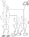
- FIG. 1 illustrates a high-level system architecture of a wireless communications system 100 in accordance with an embodiment of the invention.
- the wireless communications system 100 contains UEs 1...N.
- the UEs 1...N can include cellular telephones, personal digital assistant (PDAs), pagers, a laptop computer, a desktop computer, and so on.
- PDAs personal digital assistant
- UEs 1...2 are illustrated as cellular calling phones
- UEs 3...5 are illustrated as cellular touchscreen phones or smart phones
- UE N is illustrated as a desktop computer or PC.
- UEs 1...N are configured to communicate with an access network (e.g., the RAN 120, an access point 125, etc.) over a physical communications interface or layer, shown in FIG. 1 as air interfaces 104, 106, 108 and/or a direct wired connection.
- the air interfaces 104 and 106 can comply with a given cellular communications protocol (e.g., CDMA, EVDO, eHRPD, GSM, EDGE, W-CDMA, LTE, etc.), while the air interface 108 can comply with a wireless IP protocol (e.g., IEEE 802.11).
- the RAN 120 includes a plurality of access points that serve UEs over air interfaces, such as the air interfaces 104 and 106.
- the access points in the RAN 120 can be referred to as access nodes or ANs, access points or APs, base stations or BSs, Node Bs, eNode Bs, and so on. These access points can be terrestrial access points (or ground stations), or satellite access points.
- the RAN 120 is configured to connect to a core network 140 that can perform a variety of functions, including bridging circuit switched (CS) calls between UEs served by the RAN 120 and other UEs served by the RAN 120 or a different RAN altogether, and can also mediate an exchange of packet-switched (PS) data with external networks such as Internet 175.
- the Internet 175 includes a number of routing agents and processing agents (not shown in FIG. 1 for the sake of convenience). In FIG.
- UE N is shown as connecting to the Internet 175 directly (i.e., separate from the core network 140, such as over an Ethernet connection of WiFi or 802.11-based network).
- the Internet 175 can thereby function to bridge packet-switched data communications between UE N and UEs 1...N via the core network 140.
- the access point 125 is also shown in FIG.1 .
- the access point 125 may be connected to the Internet 175 independent of the core network 140 (e.g., via an optical communication system such as FiOS, a cable modem, etc.).
- the air interface 108 may serve UE 4 or UE 5 over a local wireless connection, such as IEEE 802.11 in an example.
- UE N is shown as a desktop computer with a wired connection to the Internet 175, such as a direct connection to a modem or router, which can correspond to the access point 125 itself in an example (e.g., for a WiFi router with both wired and wireless connectivity).
- a modem or router which can correspond to the access point 125 itself in an example (e.g., for a WiFi router with both wired and wireless connectivity).
- a server 170 is shown as connected to the Internet 175, the core network 140, or both.
- the server 170 can be implemented as a plurality of structurally separate servers, or alternately may correspond to a single server.
- the server 170 is configured to support one or more communication services (e.g., Voice-over-Internet Protocol (VoIP) sessions, Push-to-Talk (PTT) sessions, group communication sessions, social networking services, etc.) for UEs that can connect to the server 170 via the core network 140 and/or the Internet 175, and/or to provide content (e.g., web page downloads) to the UEs.
- VoIP Voice-over-Internet Protocol
- PTT Push-to-Talk
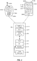
- FIG. 2 illustrates examples of UEs (i.e., client devices) in accordance with embodiments of the invention.
- UE 300A is illustrated as a calling telephone and UE 300B is illustrated as a touchscreen device (e.g., a smart phone, a tablet computer, etc.).
- an external casing of UE 300A is configured with an antenna 305A, display 310A, at least one button 315A (e.g., a PTT button, a power button, a volume control button, etc.) and a keypad 320A among other components, as is known in the art.
- button 315A e.g., a PTT button, a power button, a volume control button, etc.
- an external casing of UE 300B is configured with a touchscreen display 305B, peripheral buttons 310B, 315B, 320B and 325B (e.g., a power control button, a volume or vibrate control button, an airplane mode toggle button, etc.), at least one front-panel button 330B (e.g., a Home button, etc.), among other components, as is known in the art.
- a touchscreen display 305B peripheral buttons 310B, 315B, 320B and 325B (e.g., a power control button, a volume or vibrate control button, an airplane mode toggle button, etc.), at least one front-panel button 330B (e.g., a Home button, etc.), among other components, as is known in the art.
- the UE 300B can include one or more external antennas and/or one or more integrated antennas that are built into the external casing of UE 300B, including but not limited to WiFi antennas, cellular antennas, satellite position system (SPS) antennas (e.g., global positioning system (GPS) antennas), and so on.
- WiFi antennas e.g., WiFi
- cellular antennas e.g., cellular antennas
- satellite position system (SPS) antennas e.g., global positioning system (GPS) antennas
- GPS global positioning system
- platform 302 can receive and execute software applications, data and/or commands transmitted from the RAN 120 that may ultimately come from the core network 140, the Internet 175 and/or other remote servers and networks (e.g., application server 170, web URLs, etc.).
- the platform 302 can also independently execute locally stored applications without RAN interaction.
- the platform 302 can include a satellite positioning system (SPS) receiver 306 (e.g., for detecting SPS signals, such as GPS signals), at least one cellular transceiver 307A (e.g., for communicating with one or more cellular networks) and a WiFi transceiver 307B (e.g., for communicating with WiFi networks).
- SPS satellite positioning system
- Each of 306, 307A and 307B are operably coupled to an application specific integrated circuit (ASIC) 308, or other processor, microprocessor, logic circuit, or other data processing device.
- ASIC application specific integrated circuit
- Other transceivers or receives can also be included on the platform 302, such as Bluetooth transceivers, etc.
- the ASIC 308 or other processor executes the application programming interface (API) 310 layer that interfaces with any resident programs in the memory 312 of the wireless device.
- the memory 312 can be comprised of read-only or random-access memory (RAM and ROM), EEPROM, flash cards, or any memory common to computer platforms.
- the platform 302 also can include a local database 314 that can store applications not actively used in memory 312, as well as other data.
- the local database 314 is typically a flash memory cell, but can be any secondary storage device as known in the art, such as magnetic media, EEPROM, optical media, tape, soft or hard disk, or the like.
- an embodiment of the invention can include a UE (e.g., UE 300A, 300B, etc.) including the ability to perform the functions described herein.
- a UE e.g., UE 300A, 300B, etc.
- the various logic elements can be embodied in discrete elements, software modules executed on a processor or any combination of software and hardware to achieve the functionality disclosed herein.
- ASIC 308, memory 312, API 310 and local database 314 may all be used cooperatively to load, store and execute the various functions disclosed herein and thus the logic to perform these functions may be distributed over various elements.
- the functionality could be incorporated into one discrete component. Therefore, the features of the UEs 300A and 300B in FIG. 2 are to be considered merely illustrative and the invention is not limited to the illustrated features or arrangement.
- the wireless communication between the UEs 300A and/or 300B and the RAN 120 can be based on different technologies, such as CDMA, W-CDMA, time division multiple access (TDMA), frequency division multiple access (FDMA), Orthogonal Frequency Division Multiplexing (OFDM), GSM, or other protocols that may be used in a wireless communications network or a data communications network.
- CDMA Code Division Multiple Access
- W-CDMA time division multiple access
- FDMA frequency division multiple access
- OFDM Orthogonal Frequency Division Multiplexing
- GSM Global System for Mobile communications
- voice transmission and/or data can be transmitted to the UEs from the RAN using a variety of networks and configurations. Accordingly, the illustrations provided herein are not intended to limit the embodiments of the invention and are merely to aid in the description of aspects of embodiments of the invention.
- FIG. 3 illustrates different position determination systems that can be connected to the UE 305B from FIG. 2 in accordance with an embodiment of the invention.
- a WiFi position determination system is represented in FIG. 3 by WiFI APs 1...N
- an SPS position determination system is represented in FIG. 3 by SPS satellites 1...N.
- APs 1 and 2 are shown as positioned within a building 350, and can thereby be characterized as "indoor” APs, whereas AP N as well as satellites 1...N are "outdoor” entities.
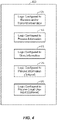
- FIG. 4 illustrates a communication device 400 that includes logic configured to perform functionality.
- the communication device 400 can correspond to any of the above-noted communication devices, including but not limited to UEs 300A or 300B, any component of the RAN 120, any component of the core network 140, any components coupled with the core network 140 and/or the Internet 175 (e.g., the server 170), and so on.
- communication device 400 can correspond to any electronic device that is configured to communicate with (or facilitate communication with) one or more other entities over the wireless communications system 100 of FIG. 1 .
- the communication device 400 includes logic configured to receive and/or transmit information 405.
- the logic configured to receive and/or transmit information 405 can include a wireless communications interface (e.g., Bluetooth, WiFi, 2G, CDMA, W-CDMA, 3G, 4G, LTE, etc.) such as a wireless transceiver and associated hardware (e.g., an RF antenna, a MODEM, a modulator and/or demodulator, etc.).
- a wireless communications interface e.g., Bluetooth, WiFi, 2G, CDMA, W-CDMA, 3G, 4G, LTE, etc.
- a wireless transceiver and associated hardware e.g., an RF antenna, a MODEM, a modulator and/or demodulator, etc.
- the logic configured to receive and/or transmit information 405 can correspond to a wired communications interface (e.g., a serial connection, a USB or Firewire connection, an Ethernet connection through which the Internet 175 can be accessed, etc.).
- a wired communications interface e.g., a serial connection, a USB or Firewire connection, an Ethernet connection through which the Internet 175 can be accessed, etc.
- the communication device 400 corresponds to some type of network-based server (e.g., server 170, etc.)
- the logic configured to receive and/or transmit information 405 can correspond to an Ethernet card, in an example, that connects the network-based server to other communication entities via an Ethernet protocol.
- the logic configured to receive and/or transmit information 405 can include sensory or measurement hardware by which the communication device 400 can monitor its local environment (e.g., an accelerometer, a temperature sensor, a light sensor, an antenna for monitoring local RF signals, etc.).
- the logic configured to receive and/or transmit information 405 can also include software that, when executed, permits the associated hardware of the logic configured to receive and/or transmit information 405 to perform its reception and/or transmission function(s).
- the logic configured to receive and/or transmit information 405 does not correspond to software alone, and the logic configured to receive and/or transmit information 405 relies at least in part upon hardware to achieve its functionality.
- the communication device 400 further includes logic configured to process information 410.
- the logic configured to process information 410 can include at least a processor.
- Example implementations of the type of processing that can be performed by the logic configured to process information 410 includes but is not limited to performing determinations, establishing connections, making selections between different information options, performing evaluations related to data, interacting with sensors coupled to the communication device 400 to perform measurement operations, converting information from one format to another (e.g., between different protocols such as .wmv to .avi, etc.), and so on.
- the processor included in the logic configured to process information 410 can correspond to a general purpose processor, a digital signal processor (DSP), an ASIC, a field programmable gate array (FPGA) or other programmable logic device, discrete gate or transistor logic, discrete hardware components, or any combination thereof designed to perform the functions described herein.
- a general purpose processor may be a microprocessor, but in the alternative, the processor may be any conventional processor, controller, microcontroller, or state machine.
- a processor may also be implemented as a combination of computing devices, e.g., a combination of a DSP and a microprocessor, a plurality of microprocessors, one or more microprocessors in conjunction with a DSP core, or any other such configuration.
- the logic configured to process information 410 can also include software that, when executed, permits the associated hardware of the logic configured to process information 410 to perform its processing function(s). However, the logic configured to process information 410 does not correspond to software alone, and the logic configured to process information 410 relies at least in part upon hardware to achieve its functionality.
- the communication device 400 further includes logic configured to store information 415.
- the logic configured to store information 415 can include at least a non-transitory memory and associated hardware (e.g., a memory controller, etc.).
- the non-transitory memory included in the logic configured to store information 415 can correspond to RAM memory, flash memory, ROM memory, EPROM memory, EEPROM memory, registers, hard disk, a removable disk, a CD-ROM, or any other form of storage medium known in the art.
- the logic configured to store information 415 can also include software that, when executed, permits the associated hardware of the logic configured to store information 415 to perform its storage function(s). However, the logic configured to store information 415 does not correspond to software alone, and the logic configured to store information 415 relies at least in part upon hardware to achieve its functionality.
- the communication device 400 further optionally includes logic configured to present information 420.
- the logic configured to present information 420 can include at least an output device and associated hardware.
- the output device can include a video output device (e.g., a display screen, a port that can carry video information such as USB, HDMI, etc.), an audio output device (e.g., speakers, a port that can carry audio information such as a microphone jack, USB, HDMI, etc.), a vibration device and/or any other device by which information can be formatted for output or actually outputted by a user or operator of the communication device 400.
- a video output device e.g., a display screen, a port that can carry video information such as USB, HDMI, etc.
- an audio output device e.g., speakers, a port that can carry audio information such as a microphone jack, USB, HDMI, etc.
- a vibration device e.g., a vibration device by which information can be formatted for output or actually outputted by a user or operator of the
- the logic configured to present information 420 can include the display 310A of UE 300A or the touchscreen display 305B of UE 300B.
- the logic configured to present information 420 can be omitted for certain communication devices, such as network communication devices that do not have a local user (e.g., network switches or routers, remote servers such as the server 170, etc.).
- the logic configured to present information 420 can also include software that, when executed, permits the associated hardware of the logic configured to present information 420 to perform its presentation function(s).
- the logic configured to present information 420 does not correspond to software alone, and the logic configured to present information 420 relies at least in part upon hardware to achieve its functionality.
- the communication device 400 further optionally includes logic configured to receive local user input 425.
- the logic configured to receive local user input 425 can include at least a user input device and associated hardware.
- the user input device can include buttons, a touchscreen display, a keyboard, a camera, an audio input device (e.g., a microphone or a port that can carry audio information such as a microphone jack, etc.), and/or any other device by which information can be received from a user or operator of the communication device 400.
- the communication device 400 corresponds to UE 300A or UE 300B as shown in FIG.
- the logic configured to receive local user input 425 can include the keypad 320A, any of the buttons 315A or 310B through 325B, the touchscreen display 305B, etc.
- the logic configured to receive local user input 425 can be omitted for certain communication devices, such as network communication devices that do not have a local user (e.g., network switches or routers, remote servers such as the server 170, etc.).
- the logic configured to receive local user input 425 can also include software that, when executed, permits the associated hardware of the logic configured to receive local user input 425 to perform its input reception function(s). However, the logic configured to receive local user input 425 does not correspond to software alone, and the logic configured to receive local user input 425 relies at least in part upon hardware to achieve its functionality.
- any software used to facilitate the functionality of the configured logics of 405 through 425 can be stored in the non-transitory memory associated with the logic configured to store information 415, such that the configured logics of 405 through 425 each performs their functionality (i.e., in this case, software execution) based in part upon the operation of software stored by the logic configured to store information 415.
- hardware that is directly associated with one of the configured logics can be borrowed or used by other configured logics from time to time.
- the processor of the logic configured to process information 410 can format data into an appropriate format before being transmitted by the logic configured to receive and/or transmit information 405, such that the logic configured to receive and/or transmit information 405 performs its functionality (i.e., in this case, transmission of data) based in part upon the operation of hardware (i.e., the processor) associated with the logic configured to process information 410.
- logic configured to as used throughout this disclosure is intended to invoke an embodiment that is at least partially implemented with hardware, and is not intended to map to software-only implementations that are independent of hardware.
- the configured logic or “logic configured to” in the various blocks are not limited to specific logic gates or elements, but generally refer to the ability to perform the functionality described herein (either via hardware or a combination of hardware and software).
- the configured logics or “logic configured to” as illustrated in the various blocks are not necessarily implemented as logic gates or logic elements despite sharing the word “logic.” Other interactions or cooperation between the logic in the various blocks will become clear to one of ordinary skill in the art from a review of the embodiments described below in more detail.
- FIG. 5 illustrates a process by which information pertaining to an indoor-to-outdoor transition region and/or an outdoor-to-indoor transition region for an enclosed environment (or building) can be generated and then selectively distributed to a set of target UEs in accordance with an embodiment of the invention.
- the enclosed environment does not need to be fully enclosed (e.g., some of its windows may be open, etc.) so long as there is a substantial partition due to infrastructure between an indoor space and an outdoor space relative to the enclosed environment.
- an operator navigates in proximity to the enclosed environment to measure location information that characterizes the indoor-to-outdoor transition region, the outdoor-to-indoor transition region, or both, 500.
- the operator UE may correspond to a UE controlled by an operator of the premises (or building) of the enclosed environment, or can alternately correspond to a device associated with the application server 170.
- a user of the operator UE may identify the entrances and exits of the enclosed environment, may walk to these entrances and exits with the operator UE, and may log location information in proximity to these locations (e.g., as measured with respect to a WiFi position determination system by the operator UE).
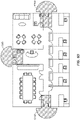
- FIG. 6A illustrates an example of the enclosed environment that can be measured by the operator UE at 500 of FIG. 5 .
- the enclosed environment corresponds to a floor of an office building with three points of entry and exit, denoted as 600A, 605A and 610A. These points of entry and exit are shown as corresponding to doorways in FIG. 6A , but alternative points of entry and exit can correspond to windows or other areas that can permit an individual to pass into or out of the enclosed environment.
- the operator UE after measuring the location information that characterizes the indoor-to-outdoor transition region, the outdoor-to-indoor transition region, or both, transmits the measured location information to the application server 170, 505, and the application server 170 adds the measured location information to a transition region database, 510.
- the transition region database can include indoor-to-outdoor transition regions and/or outdoor-to-indoor transition regions for a plurality of enclosed environments, not merely the enclosed environment that was measured at 500 by the operator UE.
- FIGS. 6B-6D illustrate examples of how the indoor-to-outdoor transition regions and/or outdoor-to-indoor transition regions for the office space of FIG. 6A can be configured within the transition region database at 510.
- indoor-to-outdoor transition regions 600B, 605B and 610B are shown as being substantially within the indoor area of the office space in proximity to the doorways 600A, 605A and 610A from FIG. 6A .
- outdoor-to-indoor transition regions 600C, 605C and 610C are shown as being substantially within the outdoor area of the office space in proximity to the doorways 600A, 605A and 610A from FIG. 6A .
- both the indoor-to-outdoor transition regions from FIG. 6B and the outdoor-to-indoor transition regions are shown as being overlaid with each other as hybrid transition regions 600D, 605D and 610D.
- one or more target UEs report location information to the application server 170 that indicates their approximate location (e.g., their geographic coordinates based on GPS, their current serving sectors, etc.), 515.
- the application server 170 provides transition region information related to the indoor-to-outdoor transition regions and/or the outdoor-to-indoor transition regions from the transition region database based on the reported location information, 520.
- the application server 170 can filter out transition region information for enclosed environments that are not proximate to the respective target UEs.
- the application server 170 can also filter out transition region information for enclosed environments that are proximate to the respective target UEs but are deemed unlikely to receive a visit from the users of the respective target UEs (e.g., users that do not drink coffee will not be provided with transition region information for coffee shops, users that do not work at a commercial office building will not receive transition region information for that commercial office building, etc.). Likewise, the application server 170 can also include transition region information for enclosed environments that are proximate to the respective target UEs and are deemed likely to receive a visit from the users of the respective target UEs (e.g., users that have a habit of smoking can be provided with transition region information for a nearby cigar shop, etc.).
- the one or more target UEs receive the transition region information from the application server 170, and then use the transition region information to determine whether to modify a position determination scheme used by the one or more target UEs, 525. Examples of how 525 can be implemented are provided in more detail below with respect to FIG. 7 .
- FIG. 5 is directed to a scenario where the transition region information is aggregated at the application server 170 and then disseminated to target UEs by the application server 170, it will be appreciated that other embodiments can be directed to different mechanisms by which the transition information region can be conveyed to the target UEs.
- a given target UE can use its own history of moving into and/or out of a given enclosed environment to identify transition regions between an indoor space and an outdoor space of the given enclosed environment.
- the target UEs can also generate and then share transition region information among themselves via ad hoc or peer-to-peer (P2P) protocols. Accordingly, it will be appreciated direct server interaction need not be used for obtaining the transition region information in at least one embodiment of the invention.
- P2P peer-to-peer
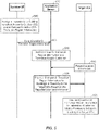
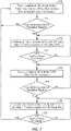
- FIG. 7 is directed to a process of dynamically changing a position determination scheme used by a given UE during transitions between an indoor space and an outdoor space relative to a particular enclosed environment (e.g., a building) in accordance with an embodiment of the invention.
- the given UE is provisioned with transition region information that characterizes both an indoor-to-outdoor transition region (or IO transition region) and an outdoor-to-indoor transition region (or OI transition region) associated with the particular enclosed environment.
- transition region information that characterizes both an indoor-to-outdoor transition region (or IO transition region) and an outdoor-to-indoor transition region (or OI transition region) associated with the particular enclosed environment.
- OI transition region outdoor-to-indoor transition region
- the given UE is equipped with an indoor positioning scheme (or IPS) (e.g., a WiFi-based positioning scheme, etc.) that can be used at least within the particular enclosed environment and an outdoor positioning scheme (or OPS) (e.g., GPS, etc.) that can be used at least outside of (and in proximity to) the particular enclosed environment.
- an indoor positioning scheme or IPS
- OPS outdoor positioning scheme
- GPS e.g., GPS, etc.
- indoor APs e.g., such as APs 1 and 2 in FIG.
- FIG. 7 is described with respect to GPS as the outdoor positioning scheme and WiFi as the indoor positioning scheme to promote clarity and for convenience of explanation (not to exclude other positioning schemes).
- any positioning scheme that can operate in the enclosed environment at a level of granularity to detect when entry into the IO transition region has occurred can be used as the indoor positioning scheme (e.g., indoor WiFi, Bluetooth, RF fingerprinting, etc.).
- the indoor positioning scheme e.g., indoor WiFi, Bluetooth, RF fingerprinting, etc.
- the outdoor positioning scheme any positioning scheme that can operate outside of the enclosed environment at a level of granularity to detect when entry into the OI transition region has occurred can be used as the outdoor positioning scheme (e.g., GPS, outdoor WiFi, cellular trilateration, a hybrid of GPS and cellular positioning techniques, RF fingerprinting, forward link trilateration (FLT), advanced forward link trilateration (AFLT), etc.).
- the given UE is positioned inside of the enclosed environment and is tracking its location via the indoor positioning scheme (e.g., WiFi-based positioning scheme) and is not tracking its location via the outdoor positioning scheme (e.g., GPS), 700.
- the given UE evaluates its location to determine whether the given UE has entered into an indoor-to-outdoor transition region of the enclosed environment, 705.
- geographical coordinates obtained via the indoor positioning scheme can be compared against the indoor-to-outdoor transition region at 705 to determine whether the UE has entered into the indoor-to-outdoor transition region.
- the UE does not need to exit the given enclosed environment where the indoor positioning scheme becomes unusable before initiating the outdoor positioning scheme.
- the enclosed environment can have multiple indoor-to-outdoor transition regions (e.g., see 600B through 610B of FIG. 6B or 600D through 610D of FIG. 6D ), and entry into any of these indoor-to-outdoor transition regions can be checked at 705. If the given UE determines that it has not entered the indoor-to-outdoor transition region, the process returns to 700 and the given UE continues to track its location via the indoor positioning scheme (e.g., WiFi-based positioning scheme) and not the outdoor positioning scheme (e.g., GPS).
- the indoor positioning scheme e.g., WiFi-based positioning scheme
- the outdoor positioning scheme e.g., GPS
- the given UE determines that it has entered the indoor-to-outdoor transition region, the given UE continues to track its location via the indoor positioning scheme (e.g., WiFi-based positioning scheme) and begins to track its location using the outdoor positioning scheme (e.g., GPS), 710. Thereby, the UE does not need to exit the given enclosed environment where the indoor positioning scheme becomes unusable before initiating the outdoor positioning scheme, but can instead launch the outdoor positioning scheme at 710 based upon entry into the indoor-to-outdoor transition region where the indoor positioning system is still useable. While not shown in FIG. 7 , if the given UE exits the indoor-to-outdoor transition region and returns to an interior location of the enclosed environment, according to the invention, the process transitions from 710 back to 700.
- the indoor positioning scheme e.g., WiFi-based positioning scheme
- the outdoor positioning scheme e.g., GPS
- the given UE evaluates the quality of the location measurements associated with the outdoor positioning system, 715. If the quality of the location measurements associated with the outdoor positioning system is determined to not be above a first quality threshold at 715, the given UE continues to use both the indoor and outdoor positioning schemes to track its location at 710 (e.g., because the outdoor positioning scheme cannot yet be relied upon exclusively for tracking the given UE's location).
- the first quality threshold may correspond to a sufficient number of GPS satellites (e.g., 4) being in-view with pseudorange errors below a threshold. Otherwise, if the quality of the location measurements associated with the outdoor positioning system is determined to rise above the first quality threshold at 715, the given UE stops tracking its location using the indoor position scheme and transitions exclusively to the outdoor positioning scheme, 720 (e.g., because the outdoor positioning scheme can now be relied upon exclusively for tracking the given UE's location). While not shown explicitly in FIG. 7 , 720 represents an alternative start point to the process of FIG. 7 if the given UE had started the process in the outdoor space instead of the indoor space relative to the enclosed environment.
- the given UE evaluates its location to determine whether the given UE has entered into an outdoor-to-indoor transition region of the enclosed environment, 725. For example, geographical coordinates obtained via the outdoor positioning scheme can be compared against the outdoor-to-indoor transition region at 725 to determine whether the UE has entered into the outdoor-to-indoor transition region.
- the enclosed environment can have multiple outdoor-to-indoor transition regions (e.g., see 600C through 610C of FIG. 6C or 600D through 610D of FIG. 6D ), and entry into any of these outdoor-to-indoor transition regions can be checked at 725. If the given UE determines that it has not entered the outdoor-to-indoor transition region, the process returns to 720 and the given UE continues to track its location via the outdoor positioning scheme (e.g., GPS) and not the indoor positioning scheme (e.g., WiFi-based transitioning scheme).
- the outdoor positioning scheme e.g., GPS
- WiFi-based transitioning scheme e.g., WiFi-based transitioning scheme
- the given UE determines that it has entered outdoor-to-indoor transition region, the given UE continues to track its location via the outdoor positioning scheme (e.g., GPS) and begins to track its location using the indoor positioning scheme (e.g., WiFi-based positioning scheme), 730.
- the outdoor positioning scheme e.g., GPS
- the indoor positioning scheme e.g., WiFi-based positioning scheme
- the UE does not need to enter the given enclosed environment where the outdoor positioning scheme becomes unusable before initiating the indoor positioning scheme, but can instead launch the indoor positioning scheme at 730 based upon entry into the outdoor-to-indoor transition region where the outdoor positioning system is still useable.
- the process transitions from 730 back to 720.
- the given UE evaluates the quality of the location measurements associated with the indoor positioning system, 735. If the quality of the location measurements associated with the indoor positioning system is determined to not be above a second quality threshold at 735, the given UE continues to use both the indoor and outdoor positioning schemes to track its location at 730 (e.g., because the indoor positioning scheme cannot yet be relied upon exclusively for tracking the given UE's location).
- the second quality threshold may correspond to a sufficient number of WiFi signals and/or a sufficient signal strength of the WiFi signals.
- the process of FIG. 7 returns to 700 where the given UE stops tracking its location using the outdoor position scheme and transitions exclusively to the indoor positioning scheme, 700 (e.g., because the indoor positioning scheme can now be relied upon exclusively for tracking the given UE's location).
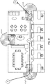
- FIG. 8 illustrates an example implementation of the process of FIG. 7 with respect to the combined transition regions 600D through 615 (i.e., transition regions that include both indoor-to-outdoor and outdoor-to-indoor transition regions) from FIG. 6D in accordance with an embodiment of the invention.
- the given UE begins outside of the enclosed environment (i.e., the office space or office building) at position 1, where the given UE tracks its location using the outdoor positioning scheme and not the indoor positioning scheme (720).
- the given UE then moves into the outdoor-to-indoor position region 605D at position 2 (725), where the given UE tracks its location using both the indoor and outdoor positioning schemes (730).
- the given UE then moves to an interior location of the enclosed environment at position 3 where the quality of the indoor positioning scheme rises above the second quality threshold (735), which prompts the given UE to stop tracking its location using the outdoor positioning scheme and instead to rely exclusively upon the indoor positioning scheme (700).
- the given UE then moves into the indoor-to-outdoor position region 610D at position 4 (705), where the given UE tracks its location using both the indoor and outdoor positioning schemes (710).
- the given UE then moves to an exterior location that is further away from the enclosed environment at position 5 where the quality of the outdoor positioning scheme rises above the first quality threshold (715), which prompts the given UE to stop tracking its location using the indoor positioning scheme and instead to rely exclusively upon the outdoor positioning scheme (720).
- DSP digital signal processor
- ASIC application specific integrated circuit
- FPGA field programmable gate array
- a general purpose processor may be a microprocessor, but in the alternative, the processor may be any conventional processor, controller, microcontroller, or state machine.
- a processor may also be implemented as a combination of computing devices, e.g., a combination of a DSP and a microprocessor, a plurality of microprocessors, one or more microprocessors in conjunction with a DSP core, or any other such configuration.
- a software module may reside in RAM memory, flash memory, ROM memory, EPROM memory, EEPROM memory, registers, hard disk, a removable disk, a CD-ROM, or any other form of storage medium known in the art.
- An exemplary storage medium is coupled to the processor such that the processor can read information from, and write information to, the storage medium.
- the storage medium may be integral to the processor.
- the processor and the storage medium may reside in an ASIC.
- the ASIC may reside in a user terminal (e.g., UE).
- the processor and the storage medium may reside as discrete components in a user terminal.
- the functions described may be implemented in hardware, software, firmware, or any combination thereof. If implemented in software, the functions may be stored on or transmitted over as one or more instructions or code on a computer-readable medium.
- Computer-readable media includes both computer storage media and communication media including any medium that facilitates transfer of a computer program from one place to another.
- a storage media may be any available media that can be accessed by a computer.
- such computer-readable media can comprise RAM, ROM, EEPROM, CD-ROM or other optical disk storage, magnetic disk storage or other magnetic storage devices, or any other medium that can be used to carry or store desired program code in the form of instructions or data structures and that can be accessed by a computer.
- any connection is properly termed a computer-readable medium.
- the software is transmitted from a website, server, or other remote source using a coaxial cable, fiber optic cable, twisted pair, digital subscriber line (DSL), or wireless technologies such as infrared, radio, and microwave
- the coaxial cable, fiber optic cable, twisted pair, DSL, or wireless technologies such as infrared, radio, and microwave are included in the definition of medium.
- Disk and disc includes compact disc (CD), laser disc, optical disc, digital versatile disc (DVD), floppy disk and blu-ray disc where disks usually reproduce data magnetically, while discs reproduce data optically with lasers. Combinations of the above should also be included within the scope of computer-readable media.
Landscapes
- Engineering & Computer Science (AREA)
- Remote Sensing (AREA)
- Radar, Positioning & Navigation (AREA)
- Physics & Mathematics (AREA)
- General Physics & Mathematics (AREA)
- Automation & Control Theory (AREA)
- Computer Networks & Wireless Communication (AREA)
- Toxicology (AREA)
- Health & Medical Sciences (AREA)
- Mobile Radio Communication Systems (AREA)
- Telephonic Communication Services (AREA)
- Telephone Function (AREA)
- Position Fixing By Use Of Radio Waves (AREA)
Applications Claiming Priority (3)
| Application Number | Priority Date | Filing Date | Title |
|---|---|---|---|
| US201261716841P | 2012-10-22 | 2012-10-22 | |
| US13/801,509 US10168161B2 (en) | 2012-10-22 | 2013-03-13 | Changing a position determination scheme used by a user equipment during a transition between indoor and outdoor spaces relative to an enclosed environment |
| PCT/US2013/066057 WO2014066311A1 (en) | 2012-10-22 | 2013-10-22 | Changing a position determination scheme used by a user equipment during a transition between indoor and outdoor spaces relative to an enclosed environment |
Publications (2)
| Publication Number | Publication Date |
|---|---|
| EP2909646A1 EP2909646A1 (en) | 2015-08-26 |
| EP2909646B1 true EP2909646B1 (en) | 2022-07-27 |
Family
ID=50486091
Family Applications (1)
| Application Number | Title | Priority Date | Filing Date |
|---|---|---|---|
| EP13789095.0A Active EP2909646B1 (en) | 2012-10-22 | 2013-10-22 | Changing a position determination scheme used by a user equipment during a transition between indoor and outdoor spaces relative to an enclosed environment |
Country Status (5)
| Country | Link |
|---|---|
| US (1) | US10168161B2 (zh) |
| EP (1) | EP2909646B1 (zh) |
| JP (2) | JP6463684B2 (zh) |
| CN (1) | CN104737030A (zh) |
| WO (1) | WO2014066311A1 (zh) |
Families Citing this family (30)
| Publication number | Priority date | Publication date | Assignee | Title |
|---|---|---|---|---|
| US9976860B2 (en) * | 2013-04-16 | 2018-05-22 | Apple Inc. | Seamless transition from outdoor to indoor mapping |
| US9642110B2 (en) * | 2013-05-09 | 2017-05-02 | Marvell World Trade Ltd. | GPS and WLAN hybrid position determination |
| US20150097731A1 (en) * | 2013-10-03 | 2015-04-09 | Motorola Mobility Llc | Gps/wifi indoor/outdoor detection |
| US9641973B2 (en) * | 2013-12-12 | 2017-05-02 | Marvell World Trade Ltd. | Method and apparatus for tracking, in real-time, a position of a mobile wireless communication device |
| US9591458B2 (en) * | 2014-03-12 | 2017-03-07 | Marvell World Trade Ltd. | Method and apparatus for adaptive positioning |
| KR102243067B1 (ko) * | 2014-05-22 | 2021-04-21 | 삼성전자주식회사 | 실내 또는 실외에 배치되는지 여부를 판단하는 전자 장치 및 그 제어 방법 |
| CN106796110B (zh) * | 2014-08-12 | 2020-04-07 | 诺基亚通信公司 | 网络元件和用户设备在室内环境中的位置确定 |
| US20160066156A1 (en) * | 2014-08-29 | 2016-03-03 | Google Inc. | Selection of Location-Determination Information |
| US9706364B2 (en) | 2014-09-16 | 2017-07-11 | Microsoft Technology Licensing, Llc | Accounting for indoor-outdoor transitions during position determination |
| US9820232B2 (en) | 2015-05-12 | 2017-11-14 | Qualcomm Incorporated | Power delay profile based indoor outdoor detection |
| EP3291617B1 (en) | 2015-05-26 | 2019-08-14 | Huawei Technologies Co., Ltd. | Mobile terminal control method, device and system |
| KR101751731B1 (ko) * | 2015-08-10 | 2017-06-29 | 숭실대학교산학협력단 | 위치 추적 시스템 및 방법 |
| KR20170019804A (ko) * | 2015-08-12 | 2017-02-22 | 삼성전자주식회사 | 전자 장치의 위치 정보 확인 방법 및 그 전자 장치 |
| CN106211078B (zh) * | 2016-09-19 | 2019-12-06 | 广州视源电子科技股份有限公司 | 定位方法、装置、设备及系统 |
| CN110268756B (zh) | 2017-02-08 | 2022-05-10 | 英国电讯有限公司 | 操作蜂窝电信网络的方法、用于该网络的节点和数据载体 |
| EP3603139B1 (en) | 2017-03-24 | 2021-05-12 | British Telecommunications Public Limited Company | Cellular telecommunications network |
| CN110326316B (zh) | 2017-03-24 | 2022-03-08 | 英国电讯有限公司 | 对网络节点进行操作的方法、网络节点和可读数据载体 |
| CA3073457C (en) * | 2017-08-23 | 2022-07-05 | Huawei Technologies Co., Ltd. | Positioning method and apparatus |
| US10539424B2 (en) | 2018-01-26 | 2020-01-21 | Honeywell International Inc. | Navigating an indoor transit system using a mobile device |
| CN111869248B (zh) | 2018-03-28 | 2023-06-27 | 英国电讯有限公司 | 管理通过ipx网络的业务流的方法、网络路由节点 |
| WO2019185766A1 (en) | 2018-03-28 | 2019-10-03 | British Telecommunications Public Limited Company | Predictive bearers in a wireless communication network |
| CN111903180B (zh) | 2018-03-28 | 2021-08-06 | 英国电讯有限公司 | 在无线通信网络中为设备建立承载的方法和装置 |
| EP3777461A1 (en) | 2018-03-29 | 2021-02-17 | British Telecommunications public limited company | Dedicated bearer management |
| US20210080280A1 (en) * | 2018-05-15 | 2021-03-18 | Nec Corporation | Positioning system and positioning method |
| JP7257166B2 (ja) * | 2019-02-13 | 2023-04-13 | セコム株式会社 | 位置推定システム、位置推定方法及びプログラム |
| EP3772227B1 (en) | 2019-07-29 | 2022-07-13 | British Telecommunications public limited company | Cellular telecommunications network |
| US11812320B2 (en) | 2019-07-29 | 2023-11-07 | British Telecommunications Public Limited Company | Initiation of transfer of user equipment to base station according to visual data |
| CN113359862B (zh) * | 2021-07-28 | 2023-05-16 | 北京理工大学 | 一种无人机进入封闭环境的控制方法及装置 |
| CN113884095B (zh) * | 2021-09-06 | 2023-11-14 | 四川华能宝兴河水电有限责任公司 | 一种定位系统及其定位方法 |
| EP4195802A1 (en) * | 2021-12-08 | 2023-06-14 | Nokia Technologies Oy | Positioning |
Citations (5)
| Publication number | Priority date | Publication date | Assignee | Title |
|---|---|---|---|---|
| CN101387699A (zh) * | 2008-10-28 | 2009-03-18 | 华南理工大学 | 一种基于rfid和gnss的联合定位方法 |
| WO2009099773A2 (en) * | 2008-02-01 | 2009-08-13 | Walker Jonathan B | Systems and methods for providing location based services (lbs) utilizing wlan and/or gps signals for seamless indoor and outdoor tracking |
| JP2011069790A (ja) * | 2009-09-28 | 2011-04-07 | Navitime Japan Co Ltd | ナビゲーションシステム、端末装置、ナビゲーションサーバ、ナビゲーション装置、および、ナビゲーション方法 |
| JP2012093319A (ja) * | 2010-10-28 | 2012-05-17 | Zenrin Datacom Co Ltd | ナビゲーション端末、ナビゲーション方法およびナビゲーションプログラム |
| CN102721972A (zh) * | 2012-06-13 | 2012-10-10 | 北京邮电大学 | 定位的方法和装置 |
Family Cites Families (13)
| Publication number | Priority date | Publication date | Assignee | Title |
|---|---|---|---|---|
| US8099106B2 (en) | 2005-08-24 | 2012-01-17 | Qualcomm Incorporated | Method and apparatus for classifying user morphology for efficient use of cell phone system resources |
| US9448072B2 (en) | 2007-05-31 | 2016-09-20 | Trx Systems, Inc. | System and method for locating, tracking, and/or monitoring the status of personnel and/or assets both indoors and outdoors |
| US8592744B2 (en) * | 2007-07-25 | 2013-11-26 | Nxp B.V. | Indoor/outdoor detection |
| JP5374703B2 (ja) | 2007-11-30 | 2013-12-25 | 測位衛星技術株式会社 | 位置情報提供システムおよび屋内送信機 |
| US9157745B2 (en) * | 2010-01-14 | 2015-10-13 | Qualcomm Incorporated | Scalable routing for mobile station navigation with location context identifier |
| US8195251B2 (en) | 2010-02-26 | 2012-06-05 | Research In Motion Limited | Reducing WLAN power consumption on a mobile device utilizing a cellular radio interface |
| US9002535B2 (en) * | 2010-05-11 | 2015-04-07 | Irobot Corporation | Navigation portals for a remote vehicle control user interface |
| US8890746B2 (en) | 2010-11-03 | 2014-11-18 | Skyhook Wireless, Inc. | Method of and system for increasing the reliability and accuracy of location estimation in a hybrid positioning system |
| KR101779966B1 (ko) | 2010-12-13 | 2017-10-10 | 한국전자통신연구원 | 위치서비스 제공방법 및 이동 단말기 |
| US20120169535A1 (en) | 2011-01-05 | 2012-07-05 | Qualcomm Incorporated | Affecting electronic device positioning functions based on measured communication network signal parameters |
| US20130065604A1 (en) * | 2011-09-13 | 2013-03-14 | Qualcomm Incorporated | Method for seamless transition from urban outdoor environments to indoor navigation |
| US8588810B2 (en) * | 2011-11-30 | 2013-11-19 | International Business Machines Corporation | Energy efficient location tracking on smart phones |
| US9482739B2 (en) * | 2012-06-29 | 2016-11-01 | Broadcom Corporation | Indoor/outdoor transition determination |
-
2013
- 2013-03-13 US US13/801,509 patent/US10168161B2/en active Active
- 2013-10-22 WO PCT/US2013/066057 patent/WO2014066311A1/en active Application Filing
- 2013-10-22 EP EP13789095.0A patent/EP2909646B1/en active Active
- 2013-10-22 JP JP2015538127A patent/JP6463684B2/ja not_active Expired - Fee Related
- 2013-10-22 CN CN201380054995.3A patent/CN104737030A/zh active Pending
-
2018
- 2018-11-02 JP JP2018207350A patent/JP6640307B2/ja not_active Expired - Fee Related
Patent Citations (5)
| Publication number | Priority date | Publication date | Assignee | Title |
|---|---|---|---|---|
| WO2009099773A2 (en) * | 2008-02-01 | 2009-08-13 | Walker Jonathan B | Systems and methods for providing location based services (lbs) utilizing wlan and/or gps signals for seamless indoor and outdoor tracking |
| CN101387699A (zh) * | 2008-10-28 | 2009-03-18 | 华南理工大学 | 一种基于rfid和gnss的联合定位方法 |
| JP2011069790A (ja) * | 2009-09-28 | 2011-04-07 | Navitime Japan Co Ltd | ナビゲーションシステム、端末装置、ナビゲーションサーバ、ナビゲーション装置、および、ナビゲーション方法 |
| JP2012093319A (ja) * | 2010-10-28 | 2012-05-17 | Zenrin Datacom Co Ltd | ナビゲーション端末、ナビゲーション方法およびナビゲーションプログラム |
| CN102721972A (zh) * | 2012-06-13 | 2012-10-10 | 北京邮电大学 | 定位的方法和装置 |
Also Published As
| Publication number | Publication date |
|---|---|
| JP6463684B2 (ja) | 2019-02-06 |
| JP6640307B2 (ja) | 2020-02-05 |
| EP2909646A1 (en) | 2015-08-26 |
| WO2014066311A1 (en) | 2014-05-01 |
| US10168161B2 (en) | 2019-01-01 |
| JP2019050596A (ja) | 2019-03-28 |
| JP2015537444A (ja) | 2015-12-24 |
| US20140114568A1 (en) | 2014-04-24 |
| CN104737030A (zh) | 2015-06-24 |
Similar Documents
| Publication | Publication Date | Title |
|---|---|---|
| EP2909646B1 (en) | Changing a position determination scheme used by a user equipment during a transition between indoor and outdoor spaces relative to an enclosed environment | |
| US11310636B2 (en) | Machine learning coordinated wireless networking | |
| US10356684B2 (en) | Method and apparatus for selecting an access point based on direction of movement | |
| KR101643479B1 (ko) | 거동 모델에 기초하여 액세스 단말에서 포지셔닝 절차를 선택적으로 수행 | |
| US20140274111A1 (en) | Inter-device transfer of accurate location information | |
| US9918348B2 (en) | Device-to-device relay selection | |
| EP2974473B1 (en) | Using motion to improve local wireless network connectivity | |
| US9380519B2 (en) | Using motion to improve local wireless network connectivity | |
| US9161294B2 (en) | Using motion to optimize place of relevance operations | |
| US9699757B2 (en) | Small cell assisted location identification for a user device | |
| US11985587B2 (en) | Communications devices, infrastructure equipment, location servers and methods | |
| EP3318094B1 (en) | Optimizing the reach of a message beacon device with respect to the number of wireless devices in reach, resource consumption and interference |
Legal Events
| Date | Code | Title | Description |
|---|---|---|---|
| PUAI | Public reference made under article 153(3) epc to a published international application that has entered the european phase |
Free format text: ORIGINAL CODE: 0009012 |
|
| 17P | Request for examination filed |
Effective date: 20150520 |
|
| AK | Designated contracting states |
Kind code of ref document: A1 Designated state(s): AL AT BE BG CH CY CZ DE DK EE ES FI FR GB GR HR HU IE IS IT LI LT LU LV MC MK MT NL NO PL PT RO RS SE SI SK SM TR |
|
| AX | Request for extension of the european patent |
Extension state: BA ME |
|
| DAX | Request for extension of the european patent (deleted) | ||
| STAA | Information on the status of an ep patent application or granted ep patent |
Free format text: STATUS: EXAMINATION IS IN PROGRESS |
|
| 17Q | First examination report despatched |
Effective date: 20190111 |
|
| STAA | Information on the status of an ep patent application or granted ep patent |
Free format text: STATUS: EXAMINATION IS IN PROGRESS |
|
| STAA | Information on the status of an ep patent application or granted ep patent |
Free format text: STATUS: EXAMINATION IS IN PROGRESS |
|
| REG | Reference to a national code |
Ref country code: DE Ref legal event code: R079 Ref document number: 602013082159 Country of ref document: DE Free format text: PREVIOUS MAIN CLASS: G01S0005020000 Ipc: G01S0005000000 |
|
| GRAP | Despatch of communication of intention to grant a patent |
Free format text: ORIGINAL CODE: EPIDOSNIGR1 |
|
| STAA | Information on the status of an ep patent application or granted ep patent |
Free format text: STATUS: GRANT OF PATENT IS INTENDED |
|
| RIC1 | Information provided on ipc code assigned before grant |
Ipc: G01S 19/48 20100101ALI20220120BHEP Ipc: G01C 21/20 20060101ALI20220120BHEP Ipc: G01S 5/02 20100101ALI20220120BHEP Ipc: G01S 5/00 20060101AFI20220120BHEP |
|
| INTG | Intention to grant announced |
Effective date: 20220217 |
|
| GRAS | Grant fee paid |
Free format text: ORIGINAL CODE: EPIDOSNIGR3 |
|
| GRAA | (expected) grant |
Free format text: ORIGINAL CODE: 0009210 |
|
| STAA | Information on the status of an ep patent application or granted ep patent |
Free format text: STATUS: THE PATENT HAS BEEN GRANTED |
|
| AK | Designated contracting states |
Kind code of ref document: B1 Designated state(s): AL AT BE BG CH CY CZ DE DK EE ES FI FR GB GR HR HU IE IS IT LI LT LU LV MC MK MT NL NO PL PT RO RS SE SI SK SM TR |
|
| REG | Reference to a national code |
Ref country code: GB Ref legal event code: FG4D |
|
| REG | Reference to a national code |
Ref country code: CH Ref legal event code: EP |
|
| REG | Reference to a national code |
Ref country code: DE Ref legal event code: R096 Ref document number: 602013082159 Country of ref document: DE |
|
| REG | Reference to a national code |
Ref country code: AT Ref legal event code: REF Ref document number: 1507420 Country of ref document: AT Kind code of ref document: T Effective date: 20220815 |
|
| REG | Reference to a national code |
Ref country code: IE Ref legal event code: FG4D |
|
| REG | Reference to a national code |
Ref country code: LT Ref legal event code: MG9D |
|
| REG | Reference to a national code |
Ref country code: NL Ref legal event code: MP Effective date: 20220727 |
|
| PG25 | Lapsed in a contracting state [announced via postgrant information from national office to epo] |
Ref country code: SE Free format text: LAPSE BECAUSE OF FAILURE TO SUBMIT A TRANSLATION OF THE DESCRIPTION OR TO PAY THE FEE WITHIN THE PRESCRIBED TIME-LIMIT Effective date: 20220727 Ref country code: RS Free format text: LAPSE BECAUSE OF FAILURE TO SUBMIT A TRANSLATION OF THE DESCRIPTION OR TO PAY THE FEE WITHIN THE PRESCRIBED TIME-LIMIT Effective date: 20220727 Ref country code: PT Free format text: LAPSE BECAUSE OF FAILURE TO SUBMIT A TRANSLATION OF THE DESCRIPTION OR TO PAY THE FEE WITHIN THE PRESCRIBED TIME-LIMIT Effective date: 20221128 Ref country code: NO Free format text: LAPSE BECAUSE OF FAILURE TO SUBMIT A TRANSLATION OF THE DESCRIPTION OR TO PAY THE FEE WITHIN THE PRESCRIBED TIME-LIMIT Effective date: 20221027 Ref country code: NL Free format text: LAPSE BECAUSE OF FAILURE TO SUBMIT A TRANSLATION OF THE DESCRIPTION OR TO PAY THE FEE WITHIN THE PRESCRIBED TIME-LIMIT Effective date: 20220727 Ref country code: LV Free format text: LAPSE BECAUSE OF FAILURE TO SUBMIT A TRANSLATION OF THE DESCRIPTION OR TO PAY THE FEE WITHIN THE PRESCRIBED TIME-LIMIT Effective date: 20220727 Ref country code: LT Free format text: LAPSE BECAUSE OF FAILURE TO SUBMIT A TRANSLATION OF THE DESCRIPTION OR TO PAY THE FEE WITHIN THE PRESCRIBED TIME-LIMIT Effective date: 20220727 Ref country code: FI Free format text: LAPSE BECAUSE OF FAILURE TO SUBMIT A TRANSLATION OF THE DESCRIPTION OR TO PAY THE FEE WITHIN THE PRESCRIBED TIME-LIMIT Effective date: 20220727 Ref country code: ES Free format text: LAPSE BECAUSE OF FAILURE TO SUBMIT A TRANSLATION OF THE DESCRIPTION OR TO PAY THE FEE WITHIN THE PRESCRIBED TIME-LIMIT Effective date: 20220727 |
|
| REG | Reference to a national code |
Ref country code: AT Ref legal event code: MK05 Ref document number: 1507420 Country of ref document: AT Kind code of ref document: T Effective date: 20220727 |
|
| PG25 | Lapsed in a contracting state [announced via postgrant information from national office to epo] |
Ref country code: PL Free format text: LAPSE BECAUSE OF FAILURE TO SUBMIT A TRANSLATION OF THE DESCRIPTION OR TO PAY THE FEE WITHIN THE PRESCRIBED TIME-LIMIT Effective date: 20220727 Ref country code: IS Free format text: LAPSE BECAUSE OF FAILURE TO SUBMIT A TRANSLATION OF THE DESCRIPTION OR TO PAY THE FEE WITHIN THE PRESCRIBED TIME-LIMIT Effective date: 20221127 Ref country code: HR Free format text: LAPSE BECAUSE OF FAILURE TO SUBMIT A TRANSLATION OF THE DESCRIPTION OR TO PAY THE FEE WITHIN THE PRESCRIBED TIME-LIMIT Effective date: 20220727 Ref country code: GR Free format text: LAPSE BECAUSE OF FAILURE TO SUBMIT A TRANSLATION OF THE DESCRIPTION OR TO PAY THE FEE WITHIN THE PRESCRIBED TIME-LIMIT Effective date: 20221028 |
|
| PG25 | Lapsed in a contracting state [announced via postgrant information from national office to epo] |
Ref country code: SM Free format text: LAPSE BECAUSE OF FAILURE TO SUBMIT A TRANSLATION OF THE DESCRIPTION OR TO PAY THE FEE WITHIN THE PRESCRIBED TIME-LIMIT Effective date: 20220727 Ref country code: RO Free format text: LAPSE BECAUSE OF FAILURE TO SUBMIT A TRANSLATION OF THE DESCRIPTION OR TO PAY THE FEE WITHIN THE PRESCRIBED TIME-LIMIT Effective date: 20220727 Ref country code: DK Free format text: LAPSE BECAUSE OF FAILURE TO SUBMIT A TRANSLATION OF THE DESCRIPTION OR TO PAY THE FEE WITHIN THE PRESCRIBED TIME-LIMIT Effective date: 20220727 Ref country code: CZ Free format text: LAPSE BECAUSE OF FAILURE TO SUBMIT A TRANSLATION OF THE DESCRIPTION OR TO PAY THE FEE WITHIN THE PRESCRIBED TIME-LIMIT Effective date: 20220727 Ref country code: AT Free format text: LAPSE BECAUSE OF FAILURE TO SUBMIT A TRANSLATION OF THE DESCRIPTION OR TO PAY THE FEE WITHIN THE PRESCRIBED TIME-LIMIT Effective date: 20220727 |
|
| REG | Reference to a national code |
Ref country code: DE Ref legal event code: R097 Ref document number: 602013082159 Country of ref document: DE |
|
| PG25 | Lapsed in a contracting state [announced via postgrant information from national office to epo] |
Ref country code: SK Free format text: LAPSE BECAUSE OF FAILURE TO SUBMIT A TRANSLATION OF THE DESCRIPTION OR TO PAY THE FEE WITHIN THE PRESCRIBED TIME-LIMIT Effective date: 20220727 Ref country code: MC Free format text: LAPSE BECAUSE OF FAILURE TO SUBMIT A TRANSLATION OF THE DESCRIPTION OR TO PAY THE FEE WITHIN THE PRESCRIBED TIME-LIMIT Effective date: 20220727 Ref country code: EE Free format text: LAPSE BECAUSE OF FAILURE TO SUBMIT A TRANSLATION OF THE DESCRIPTION OR TO PAY THE FEE WITHIN THE PRESCRIBED TIME-LIMIT Effective date: 20220727 |
|
| REG | Reference to a national code |
Ref country code: CH Ref legal event code: PL |
|
| PLBE | No opposition filed within time limit |
Free format text: ORIGINAL CODE: 0009261 |
|
| STAA | Information on the status of an ep patent application or granted ep patent |
Free format text: STATUS: NO OPPOSITION FILED WITHIN TIME LIMIT |
|
| REG | Reference to a national code |
Ref country code: BE Ref legal event code: MM Effective date: 20221031 |
|
| PG25 | Lapsed in a contracting state [announced via postgrant information from national office to epo] |
Ref country code: LU Free format text: LAPSE BECAUSE OF NON-PAYMENT OF DUE FEES Effective date: 20221022 Ref country code: AL Free format text: LAPSE BECAUSE OF FAILURE TO SUBMIT A TRANSLATION OF THE DESCRIPTION OR TO PAY THE FEE WITHIN THE PRESCRIBED TIME-LIMIT Effective date: 20220727 |
|
| 26N | No opposition filed |
Effective date: 20230502 |
|
| PG25 | Lapsed in a contracting state [announced via postgrant information from national office to epo] |
Ref country code: LI Free format text: LAPSE BECAUSE OF NON-PAYMENT OF DUE FEES Effective date: 20221031 Ref country code: CH Free format text: LAPSE BECAUSE OF NON-PAYMENT OF DUE FEES Effective date: 20221031 |
|
| PG25 | Lapsed in a contracting state [announced via postgrant information from national office to epo] |
Ref country code: SI Free format text: LAPSE BECAUSE OF FAILURE TO SUBMIT A TRANSLATION OF THE DESCRIPTION OR TO PAY THE FEE WITHIN THE PRESCRIBED TIME-LIMIT Effective date: 20220727 |
|
| PG25 | Lapsed in a contracting state [announced via postgrant information from national office to epo] |
Ref country code: BE Free format text: LAPSE BECAUSE OF NON-PAYMENT OF DUE FEES Effective date: 20221031 |
|
| PG25 | Lapsed in a contracting state [announced via postgrant information from national office to epo] |
Ref country code: IE Free format text: LAPSE BECAUSE OF NON-PAYMENT OF DUE FEES Effective date: 20221022 |
|
| PGFP | Annual fee paid to national office [announced via postgrant information from national office to epo] |
Ref country code: GB Payment date: 20230914 Year of fee payment: 11 |
|
| PGFP | Annual fee paid to national office [announced via postgrant information from national office to epo] |
Ref country code: FR Payment date: 20230914 Year of fee payment: 11 |
|
| PGFP | Annual fee paid to national office [announced via postgrant information from national office to epo] |
Ref country code: DE Payment date: 20230915 Year of fee payment: 11 |
|
| PG25 | Lapsed in a contracting state [announced via postgrant information from national office to epo] |
Ref country code: HU Free format text: LAPSE BECAUSE OF FAILURE TO SUBMIT A TRANSLATION OF THE DESCRIPTION OR TO PAY THE FEE WITHIN THE PRESCRIBED TIME-LIMIT; INVALID AB INITIO Effective date: 20131022 |
|
| PG25 | Lapsed in a contracting state [announced via postgrant information from national office to epo] |
Ref country code: CY Free format text: LAPSE BECAUSE OF FAILURE TO SUBMIT A TRANSLATION OF THE DESCRIPTION OR TO PAY THE FEE WITHIN THE PRESCRIBED TIME-LIMIT Effective date: 20220727 |