EP2909611B1 - Laboratory x-ray micro-tomography system with crystallographic grain orientation mapping capabilities - Google Patents
Laboratory x-ray micro-tomography system with crystallographic grain orientation mapping capabilities Download PDFInfo
- Publication number
- EP2909611B1 EP2909611B1 EP13789086.9A EP13789086A EP2909611B1 EP 2909611 B1 EP2909611 B1 EP 2909611B1 EP 13789086 A EP13789086 A EP 13789086A EP 2909611 B1 EP2909611 B1 EP 2909611B1
- Authority
- EP
- European Patent Office
- Prior art keywords
- ray
- sample
- detector
- laboratory
- source
- Prior art date
- Legal status (The legal status is an assumption and is not a legal conclusion. Google has not performed a legal analysis and makes no representation as to the accuracy of the status listed.)
- Active
Links
- 238000013507 mapping Methods 0.000 title claims description 15
- 238000010603 microCT Methods 0.000 title description 2
- 238000005162 X-ray Laue diffraction Methods 0.000 claims description 44
- 238000000034 method Methods 0.000 claims description 33
- 230000003287 optical effect Effects 0.000 claims description 24
- 230000033001 locomotion Effects 0.000 claims description 12
- 238000002447 crystallographic data Methods 0.000 claims description 10
- BASFCYQUMIYNBI-UHFFFAOYSA-N platinum Chemical compound [Pt] BASFCYQUMIYNBI-UHFFFAOYSA-N 0.000 claims description 6
- RYGMFSIKBFXOCR-UHFFFAOYSA-N Copper Chemical compound [Cu] RYGMFSIKBFXOCR-UHFFFAOYSA-N 0.000 claims description 4
- 230000003750 conditioning effect Effects 0.000 claims description 4
- 229910052802 copper Inorganic materials 0.000 claims description 4
- 239000010949 copper Substances 0.000 claims description 4
- 238000003384 imaging method Methods 0.000 claims description 4
- 238000012545 processing Methods 0.000 claims description 4
- ZOKXTWBITQBERF-UHFFFAOYSA-N Molybdenum Chemical compound [Mo] ZOKXTWBITQBERF-UHFFFAOYSA-N 0.000 claims description 3
- BQCADISMDOOEFD-UHFFFAOYSA-N Silver Chemical compound [Ag] BQCADISMDOOEFD-UHFFFAOYSA-N 0.000 claims description 3
- 238000010894 electron beam technology Methods 0.000 claims description 3
- PCHJSUWPFVWCPO-UHFFFAOYSA-N gold Chemical compound [Au] PCHJSUWPFVWCPO-UHFFFAOYSA-N 0.000 claims description 3
- 229910052737 gold Inorganic materials 0.000 claims description 3
- 239000010931 gold Substances 0.000 claims description 3
- 229910052750 molybdenum Inorganic materials 0.000 claims description 3
- 239000011733 molybdenum Substances 0.000 claims description 3
- 229910052697 platinum Inorganic materials 0.000 claims description 3
- 229910052709 silver Inorganic materials 0.000 claims description 3
- 239000004332 silver Substances 0.000 claims description 3
- 230000003595 spectral effect Effects 0.000 claims description 3
- WFKWXMTUELFFGS-UHFFFAOYSA-N tungsten Chemical compound [W] WFKWXMTUELFFGS-UHFFFAOYSA-N 0.000 claims description 3
- 229910052721 tungsten Inorganic materials 0.000 claims description 3
- 239000010937 tungsten Substances 0.000 claims description 3
- 230000001678 irradiating effect Effects 0.000 claims 2
- 239000000523 sample Substances 0.000 description 93
- 239000013078 crystal Substances 0.000 description 33
- 239000000463 material Substances 0.000 description 17
- 230000000694 effects Effects 0.000 description 7
- 238000001887 electron backscatter diffraction Methods 0.000 description 7
- 230000008901 benefit Effects 0.000 description 6
- 238000001514 detection method Methods 0.000 description 6
- 229910052751 metal Inorganic materials 0.000 description 6
- 239000002184 metal Substances 0.000 description 6
- 230000005855 radiation Effects 0.000 description 6
- 238000010521 absorption reaction Methods 0.000 description 5
- 238000001228 spectrum Methods 0.000 description 5
- 238000003325 tomography Methods 0.000 description 5
- 238000013459 approach Methods 0.000 description 4
- 230000008033 biological extinction Effects 0.000 description 4
- 230000000903 blocking effect Effects 0.000 description 4
- 238000002441 X-ray diffraction Methods 0.000 description 3
- 230000001143 conditioned effect Effects 0.000 description 3
- 238000005259 measurement Methods 0.000 description 3
- 230000005469 synchrotron radiation Effects 0.000 description 3
- 238000013519 translation Methods 0.000 description 3
- 230000005461 Bremsstrahlung Effects 0.000 description 2
- 238000002083 X-ray spectrum Methods 0.000 description 2
- 238000004458 analytical method Methods 0.000 description 2
- XQPRBTXUXXVTKB-UHFFFAOYSA-M caesium iodide Chemical compound [I-].[Cs+] XQPRBTXUXXVTKB-UHFFFAOYSA-M 0.000 description 2
- 239000000919 ceramic Substances 0.000 description 2
- 238000012512 characterization method Methods 0.000 description 2
- 239000002178 crystalline material Substances 0.000 description 2
- 230000007423 decrease Effects 0.000 description 2
- 230000001066 destructive effect Effects 0.000 description 2
- 230000004907 flux Effects 0.000 description 2
- 230000003993 interaction Effects 0.000 description 2
- 150000002739 metals Chemical class 0.000 description 2
- 239000000203 mixture Substances 0.000 description 2
- 239000000843 powder Substances 0.000 description 2
- 230000008569 process Effects 0.000 description 2
- 229910000838 Al alloy Inorganic materials 0.000 description 1
- 230000002238 attenuated effect Effects 0.000 description 1
- 238000005452 bending Methods 0.000 description 1
- 229910052790 beryllium Inorganic materials 0.000 description 1
- ATBAMAFKBVZNFJ-UHFFFAOYSA-N beryllium atom Chemical compound [Be] ATBAMAFKBVZNFJ-UHFFFAOYSA-N 0.000 description 1
- 230000005540 biological transmission Effects 0.000 description 1
- 230000015572 biosynthetic process Effects 0.000 description 1
- 229910052793 cadmium Inorganic materials 0.000 description 1
- BDOSMKKIYDKNTQ-UHFFFAOYSA-N cadmium atom Chemical compound [Cd] BDOSMKKIYDKNTQ-UHFFFAOYSA-N 0.000 description 1
- 239000002131 composite material Substances 0.000 description 1
- 238000010276 construction Methods 0.000 description 1
- 230000007797 corrosion Effects 0.000 description 1
- 238000005260 corrosion Methods 0.000 description 1
- 230000008878 coupling Effects 0.000 description 1
- 238000010168 coupling process Methods 0.000 description 1
- 238000005859 coupling reaction Methods 0.000 description 1
- 238000005336 cracking Methods 0.000 description 1
- 230000001351 cycling effect Effects 0.000 description 1
- 230000001419 dependent effect Effects 0.000 description 1
- 238000010586 diagram Methods 0.000 description 1
- 229910003460 diamond Inorganic materials 0.000 description 1
- 239000010432 diamond Substances 0.000 description 1
- 238000002050 diffraction method Methods 0.000 description 1
- 238000009826 distribution Methods 0.000 description 1
- 230000005684 electric field Effects 0.000 description 1
- 238000002474 experimental method Methods 0.000 description 1
- 239000000284 extract Substances 0.000 description 1
- 238000005286 illumination Methods 0.000 description 1
- 238000011065 in-situ storage Methods 0.000 description 1
- 230000000977 initiatory effect Effects 0.000 description 1
- 238000011835 investigation Methods 0.000 description 1
- 238000010884 ion-beam technique Methods 0.000 description 1
- 229910001338 liquidmetal Inorganic materials 0.000 description 1
- 238000000691 measurement method Methods 0.000 description 1
- 229910001092 metal group alloy Inorganic materials 0.000 description 1
- 238000003801 milling Methods 0.000 description 1
- 230000009467 reduction Effects 0.000 description 1
- 230000003252 repetitive effect Effects 0.000 description 1
- 238000011160 research Methods 0.000 description 1
- 230000011218 segmentation Effects 0.000 description 1
- 229910001220 stainless steel Inorganic materials 0.000 description 1
- 239000000126 substance Substances 0.000 description 1
- 239000000758 substrate Substances 0.000 description 1
- 239000013077 target material Substances 0.000 description 1
- 230000002123 temporal effect Effects 0.000 description 1
- PBYZMCDFOULPGH-UHFFFAOYSA-N tungstate Chemical compound [O-][W]([O-])(=O)=O PBYZMCDFOULPGH-UHFFFAOYSA-N 0.000 description 1
Images


Classifications
-
- G—PHYSICS
- G01—MEASURING; TESTING
- G01N—INVESTIGATING OR ANALYSING MATERIALS BY DETERMINING THEIR CHEMICAL OR PHYSICAL PROPERTIES
- G01N23/00—Investigating or analysing materials by the use of wave or particle radiation, e.g. X-rays or neutrons, not covered by groups G01N3/00 – G01N17/00, G01N21/00 or G01N22/00
- G01N23/20—Investigating or analysing materials by the use of wave or particle radiation, e.g. X-rays or neutrons, not covered by groups G01N3/00 – G01N17/00, G01N21/00 or G01N22/00 by using diffraction of the radiation by the materials, e.g. for investigating crystal structure; by using scattering of the radiation by the materials, e.g. for investigating non-crystalline materials; by using reflection of the radiation by the materials
- G01N23/207—Diffractometry using detectors, e.g. using a probe in a central position and one or more displaceable detectors in circumferential positions
-
- G—PHYSICS
- G01—MEASURING; TESTING
- G01N—INVESTIGATING OR ANALYSING MATERIALS BY DETERMINING THEIR CHEMICAL OR PHYSICAL PROPERTIES
- G01N23/00—Investigating or analysing materials by the use of wave or particle radiation, e.g. X-rays or neutrons, not covered by groups G01N3/00 – G01N17/00, G01N21/00 or G01N22/00
- G01N23/02—Investigating or analysing materials by the use of wave or particle radiation, e.g. X-rays or neutrons, not covered by groups G01N3/00 – G01N17/00, G01N21/00 or G01N22/00 by transmitting the radiation through the material
- G01N23/04—Investigating or analysing materials by the use of wave or particle radiation, e.g. X-rays or neutrons, not covered by groups G01N3/00 – G01N17/00, G01N21/00 or G01N22/00 by transmitting the radiation through the material and forming images of the material
- G01N23/046—Investigating or analysing materials by the use of wave or particle radiation, e.g. X-rays or neutrons, not covered by groups G01N3/00 – G01N17/00, G01N21/00 or G01N22/00 by transmitting the radiation through the material and forming images of the material using tomography, e.g. computed tomography [CT]
-
- G—PHYSICS
- G01—MEASURING; TESTING
- G01N—INVESTIGATING OR ANALYSING MATERIALS BY DETERMINING THEIR CHEMICAL OR PHYSICAL PROPERTIES
- G01N2223/00—Investigating materials by wave or particle radiation
- G01N2223/40—Imaging
- G01N2223/419—Imaging computed tomograph
-
- G—PHYSICS
- G01—MEASURING; TESTING
- G01N—INVESTIGATING OR ANALYSING MATERIALS BY DETERMINING THEIR CHEMICAL OR PHYSICAL PROPERTIES
- G01N2223/00—Investigating materials by wave or particle radiation
- G01N2223/60—Specific applications or type of materials
- G01N2223/606—Specific applications or type of materials texture
Definitions
- Metals, ceramics and other important materials are composed of many individual single crystal grains.
- the crystal structure of all grains is identical, but their relative crystal orientation is not identical throughout the material.
- many important engineering properties of materials are a function of the grain properties, such as grain size, boundaries, size distribution, and orientation, to list a few examples.
- Single composition poly-crystalline materials typically have no contrast to identify individual grains and boundaries in conventional x-ray tomography scans based on absorption and/or phase contrast.
- Electron backscatter diffraction imaging can be performed on the surface of polished cross-sections of materials in a scanning electron microscope to image grains and grain boundaries in two dimensions. The crystal orientation of grains is determined in EBSD. Serial sectioning with a focused ion beam milling tool and EBSD imaging can yield three dimensional (3-D) EBSD data. 3-D EBSD is a destructive measurement technique since the sample gets destroyed in the process, however.
- X-ray diffraction contrast tomography is a non-destructive approach for obtaining the 3-dimensional characterization of polycrystalline microstructures. It allows the simultaneous mapping of the crystal grain shapes, grain orientation and microstructure of polycrystals that gives rise to absorption.
- the sample is illuminated with a monochromatic beam of high energy synchrotron radiation.
- the condition for Bragg diffraction gets fulfilled by individual grains, these diffraction spots are recorded on a 2D detector placed behind the sample.
- the diffraction geometry is used to assign spots to the grains from which they arise, and to determine the crystallographic orientations of grains.
- the spots are used as projections of the grains to reconstruct the respective grain shapes.
- the technique has been applied to several materials science investigations, for example in the 3D characterization of grain boundary networks, and in-situ studies of inter-granular stress corrosion cracking in some stainless steels.
- Other materials investigated by x-ray DCT have included aluminum alloy A1 1050.
- synchrotron sources to perform these measurements are very limiting and a laboratory source diffraction CT system would close this gap. It is well known that synchrotrons generate x-rays with orders of magnitude higher brightness than laboratory sources, and the methods for DCT developed for the synchrotron require high beam brightness, which manifests itself in high beam collimation and monochromaticity.
- Laboratory sources generally have very poor brightness compared to synchrotrons since they emit a very wide bandwidth of x-ray wavelengths in terms of Bremsstrahlung. Characteristic emission lines emitted in addition to the Bremsstrahlung background are low in intensity compared to total x-ray power emitted, and the use of a monochromator (crystal monochromator or multilayer) further reduces the intensity when trying to monochromatize the beam of a laboratory source.
- a problem with proposed configurations for laboratory-source x-ray DCT systems is that their performance should be low. Since they require a focused, monochromatic beam, the resulting x-ray flux from existing laboratory x-ray sources should be too low, resulting in impractically long exposure times.
- a need continues to exist, therefore, for methods and systems capable of performing x-ray DCT analysis in the laboratory.
- the invention features a method for three dimensional crystallographic grain orientation mapping.
- a rotating sample is illuminated by a broadband, cone x-ray beam derived from a laboratory x-ray source, to generate, on an x-ray detector, a diffracted beam image.
- Data from the image coupled with information regarding an angle of sample rotation are processed (e.g., by a controller) to obtain three dimensional reconstructions of grain orientation and position.
- the invention features an apparatus for three dimensional crystallographic grain orientation mapping.
- the apparatus includes a laboratory x-ray source, one or more optional x-ray conditioning devices such as apertures for restricting the extent of the cone beam from the source, a stage for rotating the sample, a single detection system, preferably a high resolution pixilated x-ray detector, for collecting diffraction data, and a controller for processing data received by the detector, coupled with information regarding an angle of sample rotation, to generate three dimensional reconstructions of grain orientation and position.
- crystallographic mapping using x-ray DCT principles can be performed in the laboratory with one of the primary advantages of the present system being its compact size.
- the laboratory x-ray source used here is small, much less expensive, and allows constant access.
- a broadband, unfocused (cone) x-ray beam is used that more efficiently utilizes the x-rays produced by a standard laboratory source.
- the current embodiment generally relates to a method and apparatus for obtaining three dimensional crystallographic grain orientation mapping.
- the system, and corresponding method uses a laboratory x-ray source and a detection system, which is able to detect the x-rays transmitted through and diffracted by the sample at preferably at least two distances from the sample in a conebeam geometry.
- a high resolution pixilated x-ray detector is used to collect diffracted x-rays and generate diffraction data.
- a lower resolution detector is used to detect the diffracted x-rays and projection images through the sample in the projection plane.
- the sample being studied is rotated utilizing, for instance, a motion stage system with an angle of rotation ( ⁇ ), to produce a series of angular projections.
- a controller receives image data of multiple images from the detection system (obtained while rotating the sample) and performs three dimensional reconstructions of grain orientation and position.
- the system uses a "white" or broadband beam of x-ray radiation, i.e., a beam with a wide wavelength spectrum.
- a "white" or broadband beam of x-ray radiation i.e., a beam with a wide wavelength spectrum.
- the bandwidth of the x-ray beam is only restricted by the operating voltage of the x-ray source and optional absorption filters in the beam.
- each reflection off the crystal "selects" a specific wavelength or narrowband from the incident wavelength spectrum.
- d the lattice spacing
- beta ( ⁇ ) the diffraction angle
- lambda ( ⁇ ) the wavelength.
- a system controller analyzes these diffraction patterns and the images detected by the detector system and extracts crystal orientation and lattice spacing from the data.
- each grain will contribute many reflections to the diffraction patterns.
- the polychromatic diffraction pattern of a polycrystalline sample using a collimated (parallel) incident x-ray beam in general leads to a superposition of many diffraction spots for which it is not possible to decipher crystal grain association, wavelength and d-spacing.
- Laue diffraction rings which are well known in a diffraction method called powder diffraction. Powder diffraction is an established method to determine the crystal structure of a material, but does not reveal any specific grain information.
- the present system uses a specific (cone beam) geometry that leverages the fact that for a point x-ray source with a divergent beam on reflection of an extended crystal grain diffracts x-rays such that they are focused in the diffraction plane direction to a distance equal to the source-sample distance dss.
- this special plane the Laue focusing plane. This focusing effect is caused by the single crystal grain "seeing" the x-ray source under different incidence angles over the extent of the crystal grain, which then selects different wavelengths and diffraction angles for the reflection according to the aforementioned Bragg's law.
- the wavelength of the reflected x-rays is not constant across one grain in the present system, but varies dependent on the position within the grain where the x-rays strike.
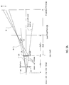
- Fig. 1 illustrates the Laue focal plane 50 and the projection plane 52.
- a broadband source 110 emits a diverging beam of broadband radiation 115. This radiation is diffracted by a crystal or grain within the sample 10.
- the diffraction effect by the crystal 10 yields the Laue focal plane 50 where the x-rays that meet the Bragg condition are focused by the diffraction in the crystal or grain 10 of the sample. Since the focusing only occurs in the diffraction plane, in general the pattern of the diffracted beam will form a line in the Laue focal plane. It is also noted that the distances between source and sample (dss) and between sample and the Laue focal plane (dsd1) are equal. Then, at a further distance from the sample 10, the projection plane 52 is found from the projection of the diffracting crystal or grain. The distance of the projection plane from the Laue focal plane is arbitrary and depends on the pixel size of the x-ray detector available to record the pattern in the projection plane.
- Fig. 2A is a top view showing the relevant distances when a broadband diverging beam is diffracted by a sample crystal grain. Specifically, the distance between the source 110 and the sample 10 is dss. The distance between the sample 10 and the Laue focal plane 50 is dsd1 and the distance between the sample 10 and the projection plane 52 is dsd2.
- the features generated at the Laue focal plane 50 are combination of multiple wavelengths, ⁇ 1, ⁇ 2, ⁇ 3. These wavelengths are within the spectral band ⁇ min to ⁇ max contained within the broadband x-rays emitted by the source 110.
- An aperture 112 is used between the source 110 and the sample 10 to restrict the illumination beam on the sample and separate the direct transmitted beam/non-diffracted beam 62, from the diffracted beam 60, 64.
- the diffracted beam 60, 64 is focused in the Laue plane, the projected image of the crystal in the projection plane is inverted and has a geometrical magnification that is given by (dsd2-dss)/dss, and can also appear sheared.
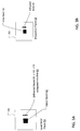
- Fig. 2B is a top view showing the relevant distances when a broadband diverging beam is diffracted by a sample crystal grain.
- the focusing effect at the Laue focal plane 50 leads to the formation of line-shaped spots.
- the appearance of the diffracted signals as line-shaped spots in the Laue focal plane comes from a focusing effect and a magnification effect.
- One such line shaped spot originates from the diffraction of X-rays off one set of planes within one crystal grain of the sample.
- the crystal planes within the grain diffract and focus the X-rays along their normal direction to a narrow line.
- This focusing effect occurs across the whole length of the crystal grain, which means that the length of the line shaped spot in the Laue focal plane is a projected representation of the diffracting grain's physical size in this direction magnified by a factor of (dss+dsd1)/dss, which is equal to 2.
- the grain is projected non-inverted in this direction.
- a spatially resolved x-ray detector 150 located at the Laue focal plane 50 detects the lines 60 that encode the orientation of the plane of the reflection.
- the lines 60 at the Laue focal plane 50 are adjacent to any x-rays that form the direct beam 62 that are not diffracted by the sample 10.
- a spatially resolved x-ray detector 152 located at the projection plane 52 detects reflected x-rays 64 onto a projection plane detector 152 that give rise to a projection of the diffracting grain.
- the magnification of the projection of the grain is not equal in the diffraction and orthogonal plane.
- the projection In the diffraction plane the projection is inverted and has a lower magnification than in the orthogonal plane.
- the projection In the orthogonal plane, the projection is non-inverted.
- One strategy to obtain a re-proj ection of the grain outline into the sample plane for the reconstruction of a 3-D grain map is to re-project the grain shape from the projection plane through the line focus in the Laue focal plane 52. This allows for the identification of the index and wavelength giving rise to the reflection, knowing the geometry of the setup (source position) along with inferences as to the exact grain location within the sample.
- FIG. 4 Shown in Fig. 4 is one example of an apparatus for conducting x-ray three dimensional crystallographic grain orientation mapping according to embodiments of the invention.
- the apparatus generally includes the x-ray source 110, for illuminating sample 10.
- the source 110 is a "laboratory x-ray source”. It is preferably located on a source z-axis stage that enables independent adjustment of source to sample distance (dss).
- a "laboratory x-ray source” is any suitable source of x-rays that is not a synchrotron x-ray radiation source.
- Source 110 can be an X-ray tube, in which electrons are accelerated in a vacuum by an electric field and shot into a target piece of metal, with x-rays being emitted as the electrons decelerate in the metal.
- X-ray tube in which electrons are accelerated in a vacuum by an electric field and shot into a target piece of metal, with x-rays being emitted as the electrons decelerate in the metal.
- x-rays being emitted as the electrons decelerate in the metal.
- such sources produce a continuous spectrum of background x-rays combined with sharp peaks in intensity at certain energies that derive from the characteristic lines of the selected target, depending on the type of metal target used.
- the x-ray beams are divergent and lack spatial and temporal coherence.
- source 110 is a rotating anode type or microfocused source, with a Tungsten target.
- Targets that include Molybdenum, Gold, Platinum, Silver or Copper also can be employed.
- a transmission configuration is used in which the electron beam strikes the thin target 410 from its backside. The x-rays emitted from the other side of the target are used as the beam 115.
- source 110 is a structured anode x-ray source such as described in U.S. Patent No. 7,443,953 issued to Yun, et al. on October 28, 2008 , the contents of which are incorporated herein by reference in their entirety.
- the source has a thin top layer made of the desired target material and a thicker bottom layer made of low atomic number and low density materials with good thermal properties.
- the anode can include, for instance, a layer of copper with an optimal thickness deposited on a layer of beryllium or diamond substrate.
- X-ray lasers producing radiation having an energy suitable for the tomographic applications described herein also can be employed.
- the source 110 is a metal jet x-ray source such as are available from Excillum AB, Kista, Sweden.
- This type of source uses microfocus tubes in which the anode is a liquid-metal jet.
- the anode is continuously regenerated and already molten.
- the x-ray beam 115 generated by source 110 is preferably conditioned to suppress unwanted energies or wavelengths of radiation. For example, undesired wavelengths present in the beam are eliminated or attenuated, using, for instance, an energy filter 412 (designed to select a desired x-ray wavelength range (bandwidth)). Nevertheless, the filter 412 does not substantially reduce the total energy or bandwidth of the transmitted beam 115. For example, the filter 412 preferably decreases the power in the beam by no greater than 50%. In the preferred embodiment, it decreases the power in the beam by no greater than 30%. The relevance is that most of the broadband x-rays generated by the x-ray source 110 are preserved to illuminate the sample 10.
- the bandwidth of the x-rays used are greater than 40% as defined by the ratio of the central x-ray energy to the full width half maximum (FWHM) of the x-ray energy band.
- FWHM full width half maximum
- the bandwidth is at least 20%, since otherwise the available flux of the source is cut too severely. It is also recognized that by collecting data with various x-ray source / filter combinations, the central energy and bandwidth are varied in some examples. This provides additional information in the data that can be used by the control system 105 to identify the wavelength range of recorded reflections.
- the beam extent is preferably reduced by passing the x-ray beam through aperture device 112, having a beam defining pinhole or appropriate square aperture.
- This aperture limits the illuminated region on the sample 10 and restricts the size of the direct beam on the x-ray detection system. It is recognized that by using different size apertures the number of crystal grains within the beam can be adjusted, which is advantageous to keep the number of diffraction reflections manageable and reduce overlap of reflections. In general, every grain will already have several reflections recorded in the Laue and projection planes.
- More than one energy filter 412 and/or aperture device 112 are employed in other implementations.
- this beam conditioning is omitted in cases in which the laboratory source (e.g., a laser) generates an adequately bandlimited and/or spatially limited beam.
- the x-ray beam 115 derived (either directly, i.e., without further conditioning, for example in the case of a laser source, or conditioned as described above) from the laboratory x-ray source 110 illuminates sample 10, the sample being studied.
- the sample 10 is a polycrystalline material having many crystal grains in which each grain constitutes a crystal with translational symmetry. While the grains can have the same chemical composition and lattice structure, they generally have different orientations.
- Examples of materials that can be analyzed using the apparatus and techniques described herein include but are not limited to metals, metal alloys, ceramics, and so forth.
- the region of interest of the sample 10 is located in the beam using the x, y, z axis translatory capability of the sample stage 414.
- the sample 10 is then rotated (see angle ⁇ ) around the y axis exposing different sample faces to the incoming x-ray beam 115.
- the sample 110 is held in a sample holder mounted on a stage 414 (not shown) which allows rotation and, in preferred implementations, translation of the sample in relation to the x-ray beam 115 to allow for alignment.
- the sample 10 can be manipulated using a conventional system, which includes a sample holder and a stage system, ideally motorized, for adjusting and rotating the sample 10.
- the stage 414 may be designed for translation along (z-axis) and/or in the transverse directions (y and x axes) of the x-ray beam 115 illuminating the sample 10, in the plane of the optical table (x-axis) and/or in a direction vertical to it (y-axis).
- the coordinate system used herein has as the z-axis the axis along optical path defined by the incoming x-ray beam; the x-axis as perpendicular to the incoming x-ray beam 115 (in the plane of the optical table); and the y-axis as projecting in a direction perpendicular (vertical) with respect to the (horizontal) plane of the optical table.
- the sample stage 414 is controlled by a system controller 105 and has a central, rotational axis y and the position of the sample can be adjusted so that this rotational axis y is perpendicular to the direct path of the x-ray beam 115.
- the stage 414 can rotate sample 10 about rotational axis y (see angle ⁇ in FIG. 4 ) either with a predefined, settable rotational speed such as in the range from 20 minutes to 24 hours per full rotation of 360° or in stepwise, incremental rotational movements that may be set such as in the range from 0.01° to 15° per incremental rotation.
- the stage can have a default reference point for the rotational position of 0° and can provide an option for setting an actual reference point at initiation of the rotational movement of a mounted sample.
- the rotational angle of the stage with respect to the reference point is communicated from the sample staging device 414 to the system controller 105.
- the sample 10 can be held on a sample holder, which projects from a base of the stage 414.
- the base can translate in the x-z plane under control of an x-z sample motion stage, allowing fine positioning of the sample on the plane of the optical table.
- a sample rotation stage rotates the sample motion stage thus also the sample 10 in the x-ray beam 115, around an axis of rotation extending parallel to the y-axis.
- An x-axis sample motion stage can be provided for relatively large or gross positioning of the sample along the x-axis, allowing, for instance, the loading of the sample.
- (translational) sample motion stage also can be provided for height adjustments of the sample 10 in the x-ray beam 115 relative to the top of the optical table.
- An x-ray stop 418 is preferably provided to block or attenuate the direct beam from the x-ray source 110.
- the advantage of blocking the direct beam using the x-ray stop 418 is that the direct beam carries little information about the grain structure of the sample 10. Moreover, since its signal strength is much stronger than any diffracted beam, blocking the direct beam improves the performance of the Laue plane x-ray detector 150 and reduces stray light generated in the scintillator 420.
- the size of the x-ray stop 418 is larger than the aperture 112 due to the diverging characteristic of the x-ray beam 115.
- the x-ray stop 418 is selected to be partially transmissive to still collect an absorption contrast projection of the sample 10 on the scintillator 420 in some examples. This direct image is useful in reconstructing the outline of the sample and determining the center of mass of the sample 10 by the controller 105.
- a further filter 416 is located between the sample 10 and the scintillator 420. This can be used to filter out any unwanted energies in the x-ray beam.
- the incoming diffraction x-ray beam 60 and transmitted (or extinction) x-ray beam 62 are converted by the scintillator 420 of the Laue plane x-ray detector 150 into photons of lower energy (typically within the visible range of the electromagnetic spectrum).
- the lower energy (typically in the visible region) photon beams emitted from transmitted x-ray image 62, if present, and from the diffracted x-ray image 60 are further handled by an optical portion 430 of the Laue plane x-ray detector 150.
- the optical portion 430 of the Laue plane x-ray detector 150 typically includes an optical magnification lens system and a detector, e.g., one using a suitable film or a camera detector based on a charge coupled device (CCD) or CMOS sensor.
- a detector e.g., one using a suitable film or a camera detector based on a charge coupled device (CCD) or CMOS sensor.
- CCD charge coupled device
- CMOS complementary metal-s
- the optical portion 430 is preferably optically disposed downstream from scintillator 420.
- the optical portion 430 preferably includes a magnification lens held within a housing. Two couplets can be used to condition the optical signal from the magnification lens.
- a final tube lens couplet forms images on the detector (e.g., a CCD camera).
- a turning mirror is included in the optical portion of the Laue plane x-ray detector 150. It is located prior to the lenses to avoid damage from the x-rays and allow any remaining x-rays to travel on to the subsequent projection plane x-ray detector 152. In the current embodiment, the Laue detector 150 is removed to take images on the projection plane detector 152. This is accomplished by the system controller 105 switching out the detector 150 using a x or y-axis motion stage/switching system 422.
- the Laue plane x-ray detector 150 is mounted utilizing the Z-axis motion stage/switching system 422 that further enables adjustment of the position of the Laue plane x-ray detector 150 in the x, y and/or z directions.
- the source to sample distance dss (in the z direction) is between 5 millimeters (mm) to 50 cm.
- the sample to Laue detector distance dsd1 (also in the z direction) can be between 5 mm to 50 cm.
- the thickness of scintillator material 420 is between 50 ⁇ m and 1 millimeters (mm). It employs cesium iodide (CsI), cadmium tungstate (CdWO4) and so forth.
- the optical portion 430 then provides magnification of about 0.4X or more.
- thickness of scintillator is between 10 ⁇ m and 500 ⁇ m, with the optical portion 430 providing a magnification of 4X.
- a thinner scintillator 420 of between 5 ⁇ m and 250 ⁇ m is used with the optical stage 430 providing a magnification of 10X.
- a thickness of 2 ⁇ m to 200 ⁇ m and an optical portion providing a magnification of 20X or more can be used as well.
- the optical portion 430 provides for magnification of about 50X or less.
- a second x-ray stop 419 is preferably provided to block the direct beam from the x-ray source 110.
- the advantage of blocking the direct beam using the x-ray stop 419 is that the direct beam carries little information about the grain structure of the sample 10.
- blocking the direct beam improves the performance of the projection plane x-ray detector 152 and reduces stray light generated in the scintillator 432 of the projection plane x-ray detector 152.
- the size of the x-ray stop 419 is larger then the aperture 112 and the first x-ray stop 418 due to the diverging characteristic of the x-ray beam 115.
- the stop is 419 is attenuating, thus allowing the detector 152 to also detect the direct beam.
- a projection detector stage 424 supports and is used to position the projection plane detector 152 along the beam axis 115.
- the incoming diffraction x-ray beam 64 and transmitted (or extinction) x-ray beam 62 are converted by the scintillator 432 of the projection plane x-ray detector 152 into photons of lower energy (typically within the visible range of the electromagnetic spectrum).
- the lower energy (typically in the visible region) photon beams emitted from transmitted direct x-ray image 62 and from diffracted x-ray image 64 are further handled by an optical portion 434 of the projection plane x-ray detector.
- the optical portion 434 of the projection plane x-ray detector 152 can be much simpler than the Laue plane x-ray detector system 150. This is because, due to the geometrical magnification, the images are larger on the projection plane detector 152.
- no optical magnification is provided.
- a CCD panel detector is used directly after the scintillator 432.
- a flat panel detector with 1:1 coupling to the scintillator 432 can be used.
- Such detectors have pixel sizes ranging typically from 50 ⁇ m to 250 ⁇ m.
- optical portion 434 of the projection plane detector 152 has a visible light magnification of 0.4X and the CMOS sensor with a pixel size of 13 ⁇ m.
- the Laue plane detector 150 and the projection plane detector 152 are the same physical detector. For each angle theta of the sample 10 relative to the beam, the detector is moved between the Laue plane 50 and the projection plane 52. This configuration requires a detector stage 422 with a large translation capability in the z and x axes.
- the sample to projection detector distance dsd2 (also in the z direction) can be between 10 cm to 100 cm.
- the geometrical magnification of the x-rays at the projection plane detector 152 is preferably between 10 and 500.
- the apparatus described herein also includes the system controller 105.
- the controller can be any processing unit suitable for carrying out the operations needed in order to obtain three dimensional crystallographic grain orientation mapping of the sample material.
- the controller 105 can be a computer system capable of receiving image data of multiple images from the detector systems 150, 152 (taken while rotating the sample 10) and for performing three dimensional reconstructions of grain orientation and position.
- the controller 105 also controls the rotation stage 414 and thus the angle of rotation of the sample 10 being examined.
- the controller 105 operates the stages 422, 424 of the Laue plane detector 150 and the projection plane detector 152. And, specifically, the controller 105 moves the Laue plane detector 150 out of the optical path to enable detection by the projection plane detector 152, or moves the Laue plane detector 150 to the position of the projection plane detector 152 to perform its function.
- the controller 105 uses only data from the Laue detector 150 or only data from the projection plane data 152 to analyze the sample 10. In general, however, the information derived from the Laue detector 150 is most helpful in the analysis of the sample.
- the controller 105 utilizes principles of x-ray DCT to generate a three dimensional crystallographic grain orientation mapping.
- Established DCT principles are described in several publications. These publications are: W. Ludwig et al., X-Ray Diffraction Contrast Tomography: A Novel Technique For Three-Dimensional Grain Mapping of Polycrystals. I. Direct Beam Case, J. Appl. Cryst. (2008) V41, pp. 302-309 (Appendix A); G. Johnson et al., X-Ray Diffraction Contrast Tomography: A Novel Technique For Three-Dimensional Grain Mapping of Polycrystals. II. The Combined Case, J. Appl. Cryst.
- x-ray DCT has some similarities to conventional X-ray absorption contrast tomography.
- grains in the sample are imaged using the occasionally occurring diffraction contribution to the X-ray attenuation coefficient each time a grain fulfils the diffraction condition.
- the three-dimensional grain shapes are reconstructed from a limited number of projections using an algebraic reconstruction technique (ART). Algorithms based on scanning orientation space and aiming at determining the corresponding crystallographic grain orientations also have been developed.
- each grain in the sample 10 produces typically multiple, 1-20, diffraction spots or lines on the Laue detector 150 at every angle of the sample 10 to the x-ray beam axis 115.
- This effect can be used to eliminate the need for continuous rotation (theta) of the sample 10.
- the line geometry of the diffraction spots in the Laue plane reduces the "overlap" problem since the lines can be separated more easily than large spots, which are detected with traditional systems.
- data from regions 60, 62, and 64 detected by the Laue detector 150 and the projection plane detector 152 are communicated with the controller 105.
- the controller 105 Besides receiving signals from transmitted image 62 and diffraction spots 60, 64 from diffracted image, the controller 105 preferably also controls the sample stage 414 so that the crystalline material sample 10 is automatically rotated during the exposure process.
- a synchrotron beam would be conditioned to deliver a diverging broadband beam to a polycrystalline sample, the same methods as described above can be employed potentially offering significant performance advantages over the currently used methods, which use a monochromatic beam.
- underutilized, low-brightness bending magnet beamlines at synchrotrons could be used instead of a laboratory source to provide the broadband, divergent x-ray beam.
Description
- This application claims the benefit under 35 USC 119(e) of
U.S. Provisional Application No. 61/715,696 - Metals, ceramics and other important materials are composed of many individual single crystal grains. For homogenous composition materials, the crystal structure of all grains is identical, but their relative crystal orientation is not identical throughout the material. In fact many important engineering properties of materials are a function of the grain properties, such as grain size, boundaries, size distribution, and orientation, to list a few examples.
- Single composition poly-crystalline materials typically have no contrast to identify individual grains and boundaries in conventional x-ray tomography scans based on absorption and/or phase contrast.
- Electron backscatter diffraction imaging (EBSD) can be performed on the surface of polished cross-sections of materials in a scanning electron microscope to image grains and grain boundaries in two dimensions. The crystal orientation of grains is determined in EBSD. Serial sectioning with a focused ion beam milling tool and EBSD imaging can yield three dimensional (3-D) EBSD data. 3-D EBSD is a destructive measurement technique since the sample gets destroyed in the process, however.
- Material evolution in the time domain as a function of external factors such as temperature cycling, stress or strain are extremely important to understand material failure and best processing conditions to yield materials with optimum properties. Since 3-D EBSD can only capture the grain map of a sample once, it is very unsatisfactory to study material evolution.
- X-ray diffraction contrast tomography (x-ray DCT) is a non-destructive approach for obtaining the 3-dimensional characterization of polycrystalline microstructures. It allows the simultaneous mapping of the crystal grain shapes, grain orientation and microstructure of polycrystals that gives rise to absorption.
- In the conventional x-ray DCT arrangement, the sample is illuminated with a monochromatic beam of high energy synchrotron radiation. As the sample is rotated, and grains pass through the illuminating beam, the condition for Bragg diffraction gets fulfilled by individual grains, these diffraction spots are recorded on a 2D detector placed behind the sample. The diffraction geometry is used to assign spots to the grains from which they arise, and to determine the crystallographic orientations of grains. The spots are used as projections of the grains to reconstruct the respective grain shapes. The technique has been applied to several materials science investigations, for example in the 3D characterization of grain boundary networks, and in-situ studies of inter-granular stress corrosion cracking in some stainless steels. Other materials investigated by x-ray DCT have included aluminum alloy A1 1050. Most importantly, it is now possible to perform routine 3-D grain map measurements non-destructively, which enables repetitive measurements to study time evolution.
- The necessity to use synchrotron sources to perform these measurements is very limiting and a laboratory source diffraction CT system would close this gap. It is well known that synchrotrons generate x-rays with orders of magnitude higher brightness than laboratory sources, and the methods for DCT developed for the synchrotron require high beam brightness, which manifests itself in high beam collimation and monochromaticity.
- Laboratory sources generally have very poor brightness compared to synchrotrons since they emit a very wide bandwidth of x-ray wavelengths in terms of Bremsstrahlung. Characteristic emission lines emitted in addition to the Bremsstrahlung background are low in intensity compared to total x-ray power emitted, and the use of a monochromator (crystal monochromator or multilayer) further reduces the intensity when trying to monochromatize the beam of a laboratory source.
- Nevertheless,
U.S. Patent Application Publication No. 2012/0008736A1, to Lauridsen et al., published on January 12, 2012 , describes an x-ray DCT system that can use a laboratory source. This system mirrors the implementation of a synchrotron DCT setup, in that it assumes the use of a focused and monochromatic x-ray beam. Additionally a scheme using non-standard detectors is described to detect the diffracted signal. - A problem with proposed configurations for laboratory-source x-ray DCT systems is that their performance should be low. Since they require a focused, monochromatic beam, the resulting x-ray flux from existing laboratory x-ray sources should be too low, resulting in impractically long exposure times.
- A need continues to exist, therefore, for methods and systems capable of performing x-ray DCT analysis in the laboratory. In particular, a need exists for techniques that make it possible to use x-ray DCT in research and industrial facilities that do not have a synchrotron radiation source. Also particularly needed are arrangements that utilize simple and effective detection systems.
- In general, according to one aspect, the invention features a method for three dimensional crystallographic grain orientation mapping. In the method, a rotating sample is illuminated by a broadband, cone x-ray beam derived from a laboratory x-ray source, to generate, on an x-ray detector, a diffracted beam image. Data from the image coupled with information regarding an angle of sample rotation are processed (e.g., by a controller) to obtain three dimensional reconstructions of grain orientation and position.
- According to another aspect, the invention features an apparatus for three dimensional crystallographic grain orientation mapping. The apparatus includes a laboratory x-ray source, one or more optional x-ray conditioning devices such as apertures for restricting the extent of the cone beam from the source, a stage for rotating the sample, a single detection system, preferably a high resolution pixilated x-ray detector, for collecting diffraction data, and a controller for processing data received by the detector, coupled with information regarding an angle of sample rotation, to generate three dimensional reconstructions of grain orientation and position.
- Utilizing the apparatus and techniques described herein, crystallographic mapping using x-ray DCT principles can be performed in the laboratory with one of the primary advantages of the present system being its compact size. Compared with the synchrotron x-ray sources typically needed in traditional x-ray DCT experiments, the laboratory x-ray source used here is small, much less expensive, and allows constant access. Furthermore, in contrast to previous approaches, a broadband, unfocused (cone) x-ray beam is used that more efficiently utilizes the x-rays produced by a standard laboratory source.
- The above and other features of the invention including various details of construction and combinations of parts, and other advantages, will now be more particularly described with reference to the accompanying drawings and pointed out in the claims. It will be understood that the particular method and device embodying the invention are shown by way of illustration and not as a limitation of the invention. The principles and features of this invention may be employed in various and numerous embodiments without departing from the scope of the invention.
- In the accompanying drawings, reference characters refer to the same parts throughout the different views. The drawings are not necessarily to scale; emphasis has instead been placed upon illustrating the principles of the invention. Of the drawings:
-
Fig. 1 is a schematic perspective view showing the Lauefocal plane 50 and theprojection plane 52 that are generated when x-rays from a broadband source illuminate one grain of a crystalline sample through an aperture; -
Fig. 2A is a side view showing the relevant distances in the set-up ofFig. 1 ; -
Fig. 2B is a top view showing the relevant distances in the set-up ofFig. 1 ; -
Fig. 3A illustrates the image generated at the Laue focal plane and relationship between the direct beam and the diffracted beam; -
Fig. 3B illustrates the image generated at the projection plane and the relationship between the direct beam in the diffracted beam; and -
Fig. 4 is a schematic diagram showing an x-ray and detector system of an apparatus that can be used to conduct x-ray DCT according to principles of the invention. - The current embodiment generally relates to a method and apparatus for obtaining three dimensional crystallographic grain orientation mapping. In contrast to previously described approaches, the system, and corresponding method, uses a laboratory x-ray source and a detection system, which is able to detect the x-rays transmitted through and diffracted by the sample at preferably at least two distances from the sample in a conebeam geometry. Preferably, a high resolution pixilated x-ray detector is used to collect diffracted x-rays and generate diffraction data. A lower resolution detector is used to detect the diffracted x-rays and projection images through the sample in the projection plane.
- During operation, the sample being studied is rotated utilizing, for instance, a motion stage system with an angle of rotation (θ), to produce a series of angular projections. A controller receives image data of multiple images from the detection system (obtained while rotating the sample) and performs three dimensional reconstructions of grain orientation and position.
- Preferably, the system uses a "white" or broadband beam of x-ray radiation, i.e., a beam with a wide wavelength spectrum. The bandwidth of the x-ray beam is only restricted by the operating voltage of the x-ray source and optional absorption filters in the beam.
- It is well known that a broadband (white) x-ray beam gives rise to diffraction patterns. For a single crystal/grain, this is referred to Laue diffraction patterns. Diffraction reflections manifest themselves at specific angles corresponding to 1) the d-spacing of the crystal planes, 2) the orientation of the planes and 3) one specific x-ray energy or narrow range of x-ray energy that is selected from the incoming broad-band x-ray spectrum to fulfill the Bragg condition for reflection.
- In polychromatic diffraction, each reflection off the crystal "selects" a specific wavelength or narrowband from the incident wavelength spectrum. Generally many reflections of one crystal grain are present in a single diffraction pattern corresponding to various crystal plane d-spacings, diffraction angles and x-ray wavelengths obeying the Bragg condition 2d*sin(β)=lambda, (or: 2d sin β = X), where d is the lattice spacing, beta (β) the diffraction angle and lambda (λ) the wavelength.
- For a single crystal material, a system controller analyzes these diffraction patterns and the images detected by the detector system and extracts crystal orientation and lattice spacing from the data.
- In a polycrystalline material that has many grains illuminated by the x-ray beam, each grain will contribute many reflections to the diffraction patterns. The polychromatic diffraction pattern of a polycrystalline sample using a collimated (parallel) incident x-ray beam in general leads to a superposition of many diffraction spots for which it is not possible to decipher crystal grain association, wavelength and d-spacing. In fact, if a large number of grains are present, the random orientation of the individual grains will give rise to so called Laue diffraction rings, which are well known in a diffraction method called powder diffraction. Powder diffraction is an established method to determine the crystal structure of a material, but does not reveal any specific grain information.
- In contrast, the present system uses a specific (cone beam) geometry that leverages the fact that for a point x-ray source with a divergent beam on reflection of an extended crystal grain diffracts x-rays such that they are focused in the diffraction plane direction to a distance equal to the source-sample distance dss. We call this special plane the Laue focusing plane. This focusing effect is caused by the single crystal grain "seeing" the x-ray source under different incidence angles over the extent of the crystal grain, which then selects different wavelengths and diffraction angles for the reflection according to the aforementioned Bragg's law.
- Different from collimated (parallel) beam polychromatic diffraction, the wavelength of the reflected x-rays is not constant across one grain in the present system, but varies dependent on the position within the grain where the x-rays strike.
-
Fig. 1 illustrates the Lauefocal plane 50 and theprojection plane 52. - In more detail, a
broadband source 110 emits a diverging beam ofbroadband radiation 115. This radiation is diffracted by a crystal or grain within thesample 10. - The diffraction effect by the
crystal 10 yields the Lauefocal plane 50 where the x-rays that meet the Bragg condition are focused by the diffraction in the crystal orgrain 10 of the sample. Since the focusing only occurs in the diffraction plane, in general the pattern of the diffracted beam will form a line in the Laue focal plane. It is also noted that the distances between source and sample (dss) and between sample and the Laue focal plane (dsd1) are equal. Then, at a further distance from thesample 10, theprojection plane 52 is found from the projection of the diffracting crystal or grain. The distance of the projection plane from the Laue focal plane is arbitrary and depends on the pixel size of the x-ray detector available to record the pattern in the projection plane. -
Fig. 2A is a top view showing the relevant distances when a broadband diverging beam is diffracted by a sample crystal grain. Specifically, the distance between thesource 110 and thesample 10 is dss. The distance between thesample 10 and the Lauefocal plane 50 is dsd1 and the distance between thesample 10 and theprojection plane 52 is dsd2. - Of interest is the fact that different wavelengths or energies within the
x-ray beam 115 meet the Bragg condition along different portions of the sample crystal orgrain 10. Thus, the features generated at the Lauefocal plane 50 are combination of multiple wavelengths, λ1, λ2, λ3. These wavelengths are within the spectral band λmin to λmax contained within the broadband x-rays emitted by thesource 110. - An
aperture 112 is used between thesource 110 and thesample 10 to restrict the illumination beam on the sample and separate the direct transmitted beam/non-diffracted beam 62, from the diffractedbeam - Since the diffracted
beam -
Fig. 2B is a top view showing the relevant distances when a broadband diverging beam is diffracted by a sample crystal grain. The focusing effect at the Lauefocal plane 50 leads to the formation of line-shaped spots. - The appearance of the diffracted signals as line-shaped spots in the Laue focal plane comes from a focusing effect and a magnification effect. One such line shaped spot originates from the diffraction of X-rays off one set of planes within one crystal grain of the sample. The crystal planes within the grain diffract and focus the X-rays along their normal direction to a narrow line. This focusing effect occurs across the whole length of the crystal grain, which means that the length of the line shaped spot in the Laue focal plane is a projected representation of the diffracting grain's physical size in this direction magnified by a factor of (dss+dsd1)/dss, which is equal to 2. The grain is projected non-inverted in this direction. From this it becomes clear that in order to be able to resolve crystal dimensions in the Laue focal plane a high-resolution detector will be required, which is able to resolve the grain dimensions since the geometric magnification is very low and equal to two. The magnification of the projection of the grain in the projection plane is given by (dss+dsd2)/dss which is identical to projection x-ray imaging systems. The larger geometrical magnification in the projection plane enables the use of lower resolution x-ray detector systems.
- For example, as illustrated in
Fig. 3A , a spatially resolvedx-ray detector 150 located at the Lauefocal plane 50 detects thelines 60 that encode the orientation of the plane of the reflection. Thelines 60 at the Lauefocal plane 50 are adjacent to any x-rays that form thedirect beam 62 that are not diffracted by thesample 10. - As illustrated in
Fig. 3B , a spatially resolvedx-ray detector 152 located at theprojection plane 52 detects reflectedx-rays 64 onto aprojection plane detector 152 that give rise to a projection of the diffracting grain. - In the projection plane, the magnification of the projection of the grain is not equal in the diffraction and orthogonal plane. In the diffraction plane the projection is inverted and has a lower magnification than in the orthogonal plane. In the orthogonal plane, the projection is non-inverted.
- One strategy to obtain a re-proj ection of the grain outline into the sample plane for the reconstruction of a 3-D grain map is to re-project the grain shape from the projection plane through the line focus in the Laue
focal plane 52. This allows for the identification of the index and wavelength giving rise to the reflection, knowing the geometry of the setup (source position) along with inferences as to the exact grain location within the sample. - The identification of Friedel pairs in the diffraction data aids in the identification of diffraction signals belonging to the same grain.
- Shown in
Fig. 4 is one example of an apparatus for conducting x-ray three dimensional crystallographic grain orientation mapping according to embodiments of the invention. The apparatus generally includes thex-ray source 110, for illuminatingsample 10. - The
source 110 is a "laboratory x-ray source". It is preferably located on a source z-axis stage that enables independent adjustment of source to sample distance (dss). As used herein, a "laboratory x-ray source" is any suitable source of x-rays that is not a synchrotron x-ray radiation source. -
Source 110 can be an X-ray tube, in which electrons are accelerated in a vacuum by an electric field and shot into a target piece of metal, with x-rays being emitted as the electrons decelerate in the metal. Typically, such sources produce a continuous spectrum of background x-rays combined with sharp peaks in intensity at certain energies that derive from the characteristic lines of the selected target, depending on the type of metal target used. Furthermore, the x-ray beams are divergent and lack spatial and temporal coherence. - In one example,
source 110 is a rotating anode type or microfocused source, with a Tungsten target. Targets that include Molybdenum, Gold, Platinum, Silver or Copper also can be employed. Preferably a transmission configuration is used in which the electron beam strikes thethin target 410 from its backside. The x-rays emitted from the other side of the target are used as thebeam 115. - In another, more specific example,
source 110 is a structured anode x-ray source such as described inU.S. Patent No. 7,443,953 issued to Yun, et al. on October 28, 2008 , the contents of which are incorporated herein by reference in their entirety. In this case, the source has a thin top layer made of the desired target material and a thicker bottom layer made of low atomic number and low density materials with good thermal properties. The anode can include, for instance, a layer of copper with an optimal thickness deposited on a layer of beryllium or diamond substrate. - X-ray lasers producing radiation having an energy suitable for the tomographic applications described herein also can be employed.
- In still another example, the
source 110 is a metal jet x-ray source such as are available from Excillum AB, Kista, Sweden. This type of source uses microfocus tubes in which the anode is a liquid-metal jet. Thus, the anode is continuously regenerated and already molten. - The
x-ray beam 115 generated bysource 110 is preferably conditioned to suppress unwanted energies or wavelengths of radiation. For example, undesired wavelengths present in the beam are eliminated or attenuated, using, for instance, an energy filter 412 (designed to select a desired x-ray wavelength range (bandwidth)). Nevertheless, thefilter 412 does not substantially reduce the total energy or bandwidth of the transmittedbeam 115. For example, thefilter 412 preferably decreases the power in the beam by no greater than 50%. In the preferred embodiment, it decreases the power in the beam by no greater than 30%. The relevance is that most of the broadband x-rays generated by thex-ray source 110 are preserved to illuminate thesample 10. In general the bandwidth of the x-rays used are greater than 40% as defined by the ratio of the central x-ray energy to the full width half maximum (FWHM) of the x-ray energy band. E.g. for a central energy of 50keV an energy band of at least 20keV around the central energy is used. In general the bandwidth is at least 20%, since otherwise the available flux of the source is cut too severely. It is also recognized that by collecting data with various x-ray source / filter combinations, the central energy and bandwidth are varied in some examples. This provides additional information in the data that can be used by thecontrol system 105 to identify the wavelength range of recorded reflections. - The beam extent is preferably reduced by passing the x-ray beam through
aperture device 112, having a beam defining pinhole or appropriate square aperture. This aperture limits the illuminated region on thesample 10 and restricts the size of the direct beam on the x-ray detection system. It is recognized that by using different size apertures the number of crystal grains within the beam can be adjusted, which is advantageous to keep the number of diffraction reflections manageable and reduce overlap of reflections. In general, every grain will already have several reflections recorded in the Laue and projection planes. - More than one
energy filter 412 and/oraperture device 112 are employed in other implementations. On the other hand, this beam conditioning is omitted in cases in which the laboratory source (e.g., a laser) generates an adequately bandlimited and/or spatially limited beam. - The
x-ray beam 115 derived (either directly, i.e., without further conditioning, for example in the case of a laser source, or conditioned as described above) from thelaboratory x-ray source 110 illuminatessample 10, the sample being studied. Often, thesample 10 is a polycrystalline material having many crystal grains in which each grain constitutes a crystal with translational symmetry. While the grains can have the same chemical composition and lattice structure, they generally have different orientations. - Examples of materials that can be analyzed using the apparatus and techniques described herein include but are not limited to metals, metal alloys, ceramics, and so forth.
- The region of interest of the
sample 10 is located in the beam using the x, y, z axis translatory capability of thesample stage 414. Thesample 10 is then rotated (see angle θ) around the y axis exposing different sample faces to theincoming x-ray beam 115. In specific examples, thesample 110 is held in a sample holder mounted on a stage 414 (not shown) which allows rotation and, in preferred implementations, translation of the sample in relation to thex-ray beam 115 to allow for alignment. - For instance, the
sample 10 can be manipulated using a conventional system, which includes a sample holder and a stage system, ideally motorized, for adjusting and rotating thesample 10. Thestage 414 may be designed for translation along (z-axis) and/or in the transverse directions (y and x axes) of thex-ray beam 115 illuminating thesample 10, in the plane of the optical table (x-axis) and/or in a direction vertical to it (y-axis). For convenience, the coordinate system used herein has as the z-axis the axis along optical path defined by the incoming x-ray beam; the x-axis as perpendicular to the incoming x-ray beam 115 (in the plane of the optical table); and the y-axis as projecting in a direction perpendicular (vertical) with respect to the (horizontal) plane of the optical table. - In one example, the
sample stage 414 is controlled by asystem controller 105 and has a central, rotational axis y and the position of the sample can be adjusted so that this rotational axis y is perpendicular to the direct path of thex-ray beam 115. Thestage 414 can rotatesample 10 about rotational axis y (see angle θ inFIG. 4 ) either with a predefined, settable rotational speed such as in the range from 20 minutes to 24 hours per full rotation of 360° or in stepwise, incremental rotational movements that may be set such as in the range from 0.01° to 15° per incremental rotation. The stage can have a default reference point for the rotational position of 0° and can provide an option for setting an actual reference point at initiation of the rotational movement of a mounted sample. The rotational angle of the stage with respect to the reference point is communicated from thesample staging device 414 to thesystem controller 105. - For instance, the
sample 10 can be held on a sample holder, which projects from a base of thestage 414. The base can translate in the x-z plane under control of an x-z sample motion stage, allowing fine positioning of the sample on the plane of the optical table. - A sample rotation stage rotates the sample motion stage thus also the
sample 10 in thex-ray beam 115, around an axis of rotation extending parallel to the y-axis. An x-axis sample motion stage can be provided for relatively large or gross positioning of the sample along the x-axis, allowing, for instance, the loading of the sample. A y-axis - (translational) sample motion stage also can be provided for height adjustments of the
sample 10 in thex-ray beam 115 relative to the top of the optical table. - Interaction of the incoming x-ray beam with the rotating sample generates a series of angular projections 60 (see
Fig. 3A ) captured on thescintillator 420 of the Laueplane x-ray detector 150. Anx-ray stop 418 is preferably provided to block or attenuate the direct beam from thex-ray source 110. The advantage of blocking the direct beam using thex-ray stop 418 is that the direct beam carries little information about the grain structure of thesample 10. Moreover, since its signal strength is much stronger than any diffracted beam, blocking the direct beam improves the performance of the Laueplane x-ray detector 150 and reduces stray light generated in thescintillator 420. In general, the size of thex-ray stop 418 is larger than theaperture 112 due to the diverging characteristic of thex-ray beam 115. - The
x-ray stop 418 is selected to be partially transmissive to still collect an absorption contrast projection of thesample 10 on thescintillator 420 in some examples. This direct image is useful in reconstructing the outline of the sample and determining the center of mass of thesample 10 by thecontroller 105. - In some implementations, a
further filter 416 is located between thesample 10 and thescintillator 420. This can be used to filter out any unwanted energies in the x-ray beam. - In either case, the incoming
diffraction x-ray beam 60 and transmitted (or extinction) x-ray beam 62 (if not blocked) are converted by thescintillator 420 of the Laueplane x-ray detector 150 into photons of lower energy (typically within the visible range of the electromagnetic spectrum). In turn, the lower energy (typically in the visible region) photon beams emitted from transmittedx-ray image 62, if present, and from the diffractedx-ray image 60 are further handled by anoptical portion 430 of the Laueplane x-ray detector 150. - The
optical portion 430 of the Laueplane x-ray detector 150 typically includes an optical magnification lens system and a detector, e.g., one using a suitable film or a camera detector based on a charge coupled device (CCD) or CMOS sensor. The image generated by the detector is provided to thesystem controller 105. - The
optical portion 430 is preferably optically disposed downstream fromscintillator 420. Theoptical portion 430 preferably includes a magnification lens held within a housing. Two couplets can be used to condition the optical signal from the magnification lens. A final tube lens couplet forms images on the detector (e.g., a CCD camera). - In some examples, a turning mirror is included in the optical portion of the Laue
plane x-ray detector 150. It is located prior to the lenses to avoid damage from the x-rays and allow any remaining x-rays to travel on to the subsequent projectionplane x-ray detector 152. In the current embodiment, theLaue detector 150 is removed to take images on theprojection plane detector 152. This is accomplished by thesystem controller 105 switching out thedetector 150 using a x or y-axis motion stage/switching system 422. - In general, suitable arrangements that can be used are described, for instance, in
U.S. Patent No. 7,130,375 B1, issued to Yun et al. on October 13, 2006 , the contents of which are incorporated herein by reference in their entirety. - The Laue
plane x-ray detector 150 is mounted utilizing the Z-axis motion stage/switching system 422 that further enables adjustment of the position of the Laueplane x-ray detector 150 in the x, y and/or z directions. - In specific examples, the source to sample distance dss (in the z direction) is between 5 millimeters (mm) to 50 cm. The sample to Laue detector distance dsd1 (also in the z direction) can be between 5 mm to 50 cm.
- In one configuration, the thickness of
scintillator material 420 is between 50 µm and 1 millimeters (mm). It employs cesium iodide (CsI), cadmium tungstate (CdWO4) and so forth. Theoptical portion 430 then provides magnification of about 0.4X or more. In another implementation, thickness of scintillator is between 10 µm and 500 µm, with theoptical portion 430 providing a magnification of 4X. In a further implementation, athinner scintillator 420 of between 5 µm and 250 µm is used with theoptical stage 430 providing a magnification of 10X. A thickness of 2 µm to 200 µm and an optical portion providing a magnification of 20X or more can be used as well. In yet other examples, theoptical portion 430 provides for magnification of about 50X or less. - Interaction of the incoming x-ray beam with the rotating sample also generates a series of
angular projections 64 captured on thescintillator 432 of the projectionplane x-ray detector 152. Asecond x-ray stop 419 is preferably provided to block the direct beam from thex-ray source 110. Here again, the advantage of blocking the direct beam using thex-ray stop 419 is that the direct beam carries little information about the grain structure of thesample 10. Moreover, since its signal strength is much stronger than any diffracted beam, blocking the direct beam improves the performance of the projectionplane x-ray detector 152 and reduces stray light generated in thescintillator 432 of the projectionplane x-ray detector 152. In general, the size of thex-ray stop 419 is larger then theaperture 112 and thefirst x-ray stop 418 due to the diverging characteristic of thex-ray beam 115. However in other embodiments, the stop is 419 is attenuating, thus allowing thedetector 152 to also detect the direct beam. - A
projection detector stage 424 supports and is used to position theprojection plane detector 152 along thebeam axis 115. - In either case, the incoming
diffraction x-ray beam 64 and transmitted (or extinction) x-ray beam 62 (if not blocked) are converted by thescintillator 432 of the projectionplane x-ray detector 152 into photons of lower energy (typically within the visible range of the electromagnetic spectrum). In turn, the lower energy (typically in the visible region) photon beams emitted from transmitteddirect x-ray image 62 and from diffractedx-ray image 64 are further handled by anoptical portion 434 of the projection plane x-ray detector. - The
optical portion 434 of the projectionplane x-ray detector 152 can be much simpler than the Laue planex-ray detector system 150. This is because, due to the geometrical magnification, the images are larger on theprojection plane detector 152. - In one example, no optical magnification is provided. Instead a CCD panel detector is used directly after the
scintillator 432. For example, a flat panel detector with 1:1 coupling to thescintillator 432 can be used. Such detectors have pixel sizes ranging typically from 50µm to 250µm. - In another example,
optical portion 434 of theprojection plane detector 152 has a visible light magnification of 0.4X and the CMOS sensor with a pixel size of 13 µm. - In one simple example, the
Laue plane detector 150 and theprojection plane detector 152 are the same physical detector. For each angle theta of thesample 10 relative to the beam, the detector is moved between theLaue plane 50 and theprojection plane 52. This configuration requires adetector stage 422 with a large translation capability in the z and x axes. - In specific examples, the sample to projection detector distance dsd2 (also in the z direction) can be between 10 cm to 100 cm. The geometrical magnification of the x-rays at the
projection plane detector 152 is preferably between 10 and 500. - The apparatus described herein also includes the
system controller 105. The controller can be any processing unit suitable for carrying out the operations needed in order to obtain three dimensional crystallographic grain orientation mapping of the sample material. For instance, thecontroller 105 can be a computer system capable of receiving image data of multiple images from thedetector systems 150, 152 (taken while rotating the sample 10) and for performing three dimensional reconstructions of grain orientation and position. In specific implementations, thecontroller 105 also controls therotation stage 414 and thus the angle of rotation of thesample 10 being examined. Preferably, also thecontroller 105 operates thestages Laue plane detector 150 and theprojection plane detector 152. And, specifically, thecontroller 105 moves theLaue plane detector 150 out of the optical path to enable detection by theprojection plane detector 152, or moves theLaue plane detector 150 to the position of theprojection plane detector 152 to perform its function. - In some cases, the
controller 105 uses only data from theLaue detector 150 or only data from theprojection plane data 152 to analyze thesample 10. In general, however, the information derived from theLaue detector 150 is most helpful in the analysis of the sample. - In many aspects of the invention, the
controller 105 utilizes principles of x-ray DCT to generate a three dimensional crystallographic grain orientation mapping. Established DCT principles are described in several publications. These publications are: W. Ludwig et al., X-Ray Diffraction Contrast Tomography: A Novel Technique For Three-Dimensional Grain Mapping of Polycrystals. I. Direct Beam Case, J. Appl. Cryst. (2008) V41, pp. 302-309 (Appendix A); G. Johnson et al., X-Ray Diffraction Contrast Tomography: A Novel Technique For Three-Dimensional Grain Mapping of Polycrystals. II. The Combined Case, J. Appl. Cryst. (2008) V41, pp. 310-318; Martin Knapič, Seminar, 4th Year, University of Ljubliana, Facutly of Mathematics and Physics, Physics Department, May 28, 2011 (Appendix C); andU.S. Patent Application Publication No. 2012/0008736A1, to E. M. Lauridsen et al., published on January 12, 2012 (Appendix D). - As described in the literature (see, e.g., Ludwig, et al. (2008). J. Appl. Cryst. 41, 302-309) x-ray DCT has some similarities to conventional X-ray absorption contrast tomography. Typically, grains in the sample are imaged using the occasionally occurring diffraction contribution to the X-ray attenuation coefficient each time a grain fulfils the diffraction condition. The three-dimensional grain shapes are reconstructed from a limited number of projections using an algebraic reconstruction technique (ART). Algorithms based on scanning orientation space and aiming at determining the corresponding crystallographic grain orientations also have been developed.
- By simultaneous acquisition of the transmitted and the diffracted beams, the technique described by Ludwig, et al. (2008). J. Appl. Cryst. 41, 302-309 has been extended (see, e.g., G. Johnson et al., J. Appl. Cryst. (2008) V41, pp. 310-318) to the study of underformed polycrystalline samples containing more than 100 grains per cross section. Here, the grains are still imaged using the occasionally occurring diffraction contribution to the X-ray attenuation coefficient (which can be observed as a reduction in the intensity of the transmitted or
direct beam 62 when a grain fulfils the diffraction condition). The segmentation of the extinction spot images with the additional diffracted beam information has been automated even in the presence of significant spot overlap. By pairing the corresponding direct ('extinction') and diffracted beam spots a robust sorting and indexing approach has been developed. - In general, with the present system, each grain in the
sample 10 produces typically multiple, 1-20, diffraction spots or lines on theLaue detector 150 at every angle of thesample 10 to thex-ray beam axis 115. This effect can be used to eliminate the need for continuous rotation (theta) of thesample 10. Additionally, the line geometry of the diffraction spots in the Laue plane reduces the "overlap" problem since the lines can be separated more easily than large spots, which are detected with traditional systems. - In one embodiment, data from
regions Laue detector 150 and theprojection plane detector 152 are communicated with thecontroller 105. Besides receiving signals from transmittedimage 62 anddiffraction spots controller 105 preferably also controls thesample stage 414 so that thecrystalline material sample 10 is automatically rotated during the exposure process. - While this invention has been particularly shown and described with references to preferred embodiments thereof, it will be understood by those skilled in the art that various changes in form and details may be made therein without departing from the scope of the invention encompassed by the appended claims.
- For example, use of a broadband x-ray spectrum for DCT has not been considered at synchrotron radiation sources. If a synchrotron beam would be conditioned to deliver a diverging broadband beam to a polycrystalline sample, the same methods as described above can be employed potentially offering significant performance advantages over the currently used methods, which use a monochromatic beam. In fact, underutilized, low-brightness bending magnet beamlines at synchrotrons could be used instead of a laboratory source to provide the broadband, divergent x-ray beam.
Claims (24)
- A method for three dimensional crystallographic grain orientation mapping, the method comprising:illuminating a rotating polycrystalline sample with a broadband x-ray beam derived from a laboratory x-ray source;detecting, on one or more x-ray detectors, diffracted beams from the sample; andprocessing data from said diffracted beams with the sample in different rotation positions to generate three dimensional reconstructions of grain orientation, position, and/or 3-D volume.
- The method of claim 1, wherein, before illuminating the sample, the x ray beam generated by the laboratory x-ray source is passed through an aperture that controls beam divergence.
- The method of claim 1, wherein, before illuminating the sample, the beam generated by the laboratory x-ray source is filtered to control its bandwidth.
- The method of claim 1, wherein, after being transmitted through the sample, the beam generated by the laboratory x-ray source is filtered to remove unwanted energies in the x-ray beam.
- The method of claim 1, wherein the beam that illuminates the sample is a cone beam.
- The method of claim 1, wherein the beam that illuminates the sample is an unfocused x-ray beam.
- The method of claim 1, wherein the one or more x-ray detectors comprise a high resolution pixilated x-ray detector to collect diffracted x-rays and generate diffraction data and a lower resolution detector to detect projection images through the sample.
- The method of claim 1, further comprising positioning an x-ray detector at a Laue focal plane.
- The method of claim 1, further comprising generating the broadband x-ray beam by irradiating a Tungsten, Molybdenum, Gold, Platinum, Silver, or Copper target with an electron beam.
- The method of claim 1, further comprising conditioning the x-ray beam that illuminates the sample with a spectral filter that reduces a total power in the beam by no greater than 50%.
- The method of claim 1, further comprising rotating the sample in stepwise, incremental rotational movements in the range from 0.01° to 15° per incremental rotation.
- The method of claim 1, further comprising providing an x-ray stop to block or attenuate a direct beam from the x-ray source from reaching an x-ray detector.
- An apparatus for conducting three dimensional crystallographic grain orientation mapping, comprising:a laboratory x-ray source generating a broadband x-ray beam;a sample rotation stage for rotating the sample in the x-ray beam;at least one x-ray detector to collect diffraction data from the sample; anda controller for receiving the diffraction data from the detector for different rotation positions of the sample and performing three dimensional reconstructions of grain orientation and position.
- The apparatus of claim 13, further comprising a beam defining aperture for limiting an illuminated area on the sample and restricting the size of a direct beam on the detector.
- The apparatus of claim 13, wherein the detector comprises a scintillator and an optical portion for magnifying and collecting photons generated from the scintillator by the broadband x ray beam diffracted by the sample.
- The apparatus of claim 13, further comprising a spectral filter that reduces a bandwidth of the x-ray beam that illuminates the sample.
- The apparatus of claim 13, wherein the beam that illuminates the sample is a cone beam.
- The apparatus of claim 13, wherein the beam that illuminates the sample is an unfocused x-ray beam.
- The apparatus of claim 13, wherein the at least one x-ray detector comprises a high resolution pixilated x-ray detector to collect diffracted x-rays and generate diffraction data and a lower resolution detector to detect projection images through the sample.
- The apparatus of claim 13, wherein the at least one x-ray detector comprises an x-ray detector at a Laue focal plane.
- The apparatus of claim 13, wherein the laboratory x-ray source generates the broadband x-ray beam by irradiating a Tungsten, Molybdenum, Gold, Platinum, Silver or Copper target with an electron beam.
- The apparatus of claim 13, wherein the sample rotation stage rotates the sample in stepwise, incremental rotational movements in the range from 0.01° to 15° per incremental rotation.
- The apparatus of claim 13, further comprising an x-ray stop to block or attenuate a direct beam from the x-ray source from reaching an x-ray detector.
- A projection x-ray imaging system for three dimensional crystallographic grain orientation mapping, comprising:a laboratory x-ray source for generating a broadband x ray beam;a beam defining aperture that limits the illuminated area on the sample and restricts the size of the direct beam;a sample motion stage system with a rotation stage to acquire a series of angular projections;at least one detector to collect diffraction data for different rotation positions of the rotation stage; anda controller that receives the diffraction data from the detector for the different rotation positions and performs three dimensional reconstructions of grain orientation and position based on the diffraction data for the different rotation positions.
Applications Claiming Priority (2)
| Application Number | Priority Date | Filing Date | Title |
|---|---|---|---|
| US201261715696P | 2012-10-18 | 2012-10-18 | |
| PCT/US2013/065584 WO2014063002A1 (en) | 2012-10-18 | 2013-10-18 | Laboratory x-ray micro-tomography system with crystallographic grain orientation mapping capabilities |
Publications (2)
| Publication Number | Publication Date |
|---|---|
| EP2909611A1 EP2909611A1 (en) | 2015-08-26 |
| EP2909611B1 true EP2909611B1 (en) | 2016-04-13 |
Family
ID=49553829
Family Applications (1)
| Application Number | Title | Priority Date | Filing Date |
|---|---|---|---|
| EP13789086.9A Active EP2909611B1 (en) | 2012-10-18 | 2013-10-18 | Laboratory x-ray micro-tomography system with crystallographic grain orientation mapping capabilities |
Country Status (6)
| Country | Link |
|---|---|
| US (2) | US9110004B2 (en) |
| EP (1) | EP2909611B1 (en) |
| JP (1) | JP6039093B2 (en) |
| KR (1) | KR102003202B1 (en) |
| CN (1) | CN104737005B (en) |
| WO (1) | WO2014063002A1 (en) |
Families Citing this family (16)
| Publication number | Priority date | Publication date | Assignee | Title |
|---|---|---|---|---|
| CN104737005B (en) * | 2012-10-18 | 2017-09-29 | 卡尔蔡司X射线显微镜公司 | The Laboratory X-ray microfault scanning system of mapping function is orientated with crystal grain |
| EP2775295B8 (en) * | 2013-03-05 | 2016-05-18 | Danmarks Tekniske Universitet | An X-ray diffraction method of mapping grain structures in a crystalline material sample, and an X-ray diffraction apparatus. |
| US9222900B2 (en) | 2013-03-05 | 2015-12-29 | Danmarks Tekniske Universitet Of Anker Engelundsvej | X-ray diffraction method of mapping grain structures in a crystalline material sample, and an X-ray diffraction apparatus |
| US9222901B2 (en) | 2013-03-05 | 2015-12-29 | Danmarks Tekniske Universitet Anker Engelundsvej | X-ray diffraction method of mapping grain structures in a crystalline material sample, and an X-ray diffraction apparatus |
| WO2015012850A1 (en) * | 2013-07-25 | 2015-01-29 | Analogic Corporation | Generation of diffraction signature of item within object |
| KR102025361B1 (en) * | 2014-07-10 | 2019-09-25 | 한화테크윈 주식회사 | Auto focussing system and method |
| GB201421837D0 (en) * | 2014-12-09 | 2015-01-21 | Reishig Peter | A method of generating a fingerprint for a gemstone using X-ray imaging |
| EP3223002B1 (en) * | 2016-03-23 | 2021-04-28 | Carl Zeiss X-Ray Microscopy, Inc. | Method, tool and computer program product for measurement and estimation of an x-ray source spectrum in computed tomography, and x-ray ct system |
| CN105869179A (en) * | 2016-06-06 | 2016-08-17 | 青岛晶维科创医药工程有限公司 | Crystal particle three-dimensional imaging system and method |
| CN108376656B (en) * | 2018-02-08 | 2020-07-31 | 北京科技大学 | Nondestructive testing method for oversized crystal grain size based on two-dimensional X-ray detection technology |
| US11275039B2 (en) * | 2018-07-25 | 2022-03-15 | Bruker Axs, Inc. | Divergent beam two dimensional diffraction |
| CN109490343A (en) * | 2018-12-04 | 2019-03-19 | 西北工业大学 | A kind of serial crystallography sample transport device and method |
| CN114424054B (en) * | 2019-06-24 | 2024-03-22 | Sms集团有限公司 | Apparatus and method for determining material properties of polycrystalline product |
| JP2023539007A (en) | 2020-07-15 | 2023-09-13 | デンマークス、テクニスケ、ウニベルシテット | Laboratory-based 3D scanning X-ray Laue microdiffraction system and method (LAB3DμXRD) |
| EP4019951A1 (en) | 2020-12-24 | 2022-06-29 | Inel S.A.S | Apparatuses and methods for combined simultaneous analyses of materials |
| CN117916586A (en) * | 2021-06-16 | 2024-04-19 | 卡尔蔡司有限公司 | Laboratory crystal X-ray diffraction analysis system |
Family Cites Families (17)
| Publication number | Priority date | Publication date | Assignee | Title |
|---|---|---|---|---|
| DE2312507A1 (en) | 1973-03-13 | 1974-09-26 | Max Planck Gesellschaft | DEVICE FOR X-RAY DIFFICULTY MEASUREMENTS USING WHITE X-RAYS |
| FR2668262B1 (en) | 1990-10-23 | 1994-04-01 | Centre Nal Recherc Scientifique | X-RAY ANALYSIS PROCESS FOR MONOCRYSTALLINE PARTS. |
| US5491738A (en) | 1993-03-15 | 1996-02-13 | The United States Of America As Represented By The Administrator Of The National Aeronautics And Space Administration | X-ray diffraction apparatus |
| JP3684745B2 (en) * | 1997-02-25 | 2005-08-17 | Jfeスチール株式会社 | Crystal grain 3D display method |
| US7130375B1 (en) | 2004-01-14 | 2006-10-31 | Xradia, Inc. | High resolution direct-projection type x-ray microtomography system using synchrotron or laboratory-based x-ray source |
| CN1264011C (en) * | 2004-04-06 | 2006-07-12 | 中国科学院上海光学精密机械研究所 | Time resolution x-ray diffraction chromatography appts. |
| WO2006113908A2 (en) * | 2005-04-20 | 2006-10-26 | The Regents Of The University Of California | Crytomography x-ray microscope stage |
| US7443953B1 (en) | 2005-12-09 | 2008-10-28 | Xradia, Inc. | Structured anode X-ray source for X-ray microscopy |
| JP4589882B2 (en) * | 2006-02-14 | 2010-12-01 | 株式会社リガク | Back reflection X-ray diffraction image observation device |
| KR101061425B1 (en) * | 2006-07-12 | 2011-09-01 | 포항공과대학교 산학협력단 | Brightfield shooting method using X-ray |
| US7978821B1 (en) * | 2008-02-15 | 2011-07-12 | The United States Of America As Represented By The Secretary Of The Air Force | Laue crystallographic orientation mapping system |
| US8130908B2 (en) * | 2009-02-23 | 2012-03-06 | X-Ray Optical Systems, Inc. | X-ray diffraction apparatus and technique for measuring grain orientation using x-ray focusing optic |
| US20120097835A1 (en) * | 2009-05-19 | 2012-04-26 | BioNano Geneomics, Inc. | Devices and methods for dynamic determination of sample position and orientation and dynamic repositioning |
| DK201070324A (en) * | 2010-07-09 | 2012-01-10 | Univ Danmarks Tekniske | An X-ray diffraction contrast tomography (DCT) system, and an X-ray diffraction contrast tomography (DCT) method |
| FR2965921B1 (en) * | 2010-10-11 | 2012-12-14 | Commissariat Energie Atomique | METHOD FOR MEASURING THE ORIENTATION AND ELASTIC DEFORMATION OF GRAINS IN MULTICRYSTALLINE MATERIALS |
| CN104737005B (en) * | 2012-10-18 | 2017-09-29 | 卡尔蔡司X射线显微镜公司 | The Laboratory X-ray microfault scanning system of mapping function is orientated with crystal grain |
| EP2775295B8 (en) | 2013-03-05 | 2016-05-18 | Danmarks Tekniske Universitet | An X-ray diffraction method of mapping grain structures in a crystalline material sample, and an X-ray diffraction apparatus. |
-
2013
- 2013-10-18 CN CN201380054570.2A patent/CN104737005B/en active Active
- 2013-10-18 JP JP2015538045A patent/JP6039093B2/en active Active
- 2013-10-18 US US14/057,126 patent/US9110004B2/en active Active
- 2013-10-18 EP EP13789086.9A patent/EP2909611B1/en active Active
- 2013-10-18 KR KR1020157011836A patent/KR102003202B1/en active IP Right Grant
- 2013-10-18 WO PCT/US2013/065584 patent/WO2014063002A1/en active Application Filing
-
2015
- 2015-07-13 US US14/797,872 patent/US9383324B2/en active Active
Also Published As
| Publication number | Publication date |
|---|---|
| WO2014063002A1 (en) | 2014-04-24 |
| JP2015533415A (en) | 2015-11-24 |
| US9110004B2 (en) | 2015-08-18 |
| CN104737005B (en) | 2017-09-29 |
| KR102003202B1 (en) | 2019-07-24 |
| US20140112433A1 (en) | 2014-04-24 |
| KR20150068436A (en) | 2015-06-19 |
| EP2909611A1 (en) | 2015-08-26 |
| JP6039093B2 (en) | 2016-12-07 |
| US9383324B2 (en) | 2016-07-05 |
| US20150316493A1 (en) | 2015-11-05 |
| CN104737005A (en) | 2015-06-24 |
Similar Documents
| Publication | Publication Date | Title |
|---|---|---|
| EP2909611B1 (en) | Laboratory x-ray micro-tomography system with crystallographic grain orientation mapping capabilities | |
| Drakopoulos et al. | I12: the joint engineering, environment and processing (JEEP) beamline at diamond light source | |
| US8971483B2 (en) | X-ray composite apparatus | |
| JP4278108B2 (en) | Ultra-small angle X-ray scattering measurement device | |
| US20170052128A1 (en) | Detector for x-rays with high spatial and high spectral resolution | |
| KR20190015531A (en) | Method and Apparatus for X-ray Microscopy Observation | |
| Peetermans et al. | Cold neutron diffraction contrast tomography of polycrystalline material | |
| CN110530907B (en) | X-ray absorption measurement system | |
| KR20130112001A (en) | X-ray topography apparatus | |
| JP3834652B2 (en) | X-ray diffraction microscope apparatus and X-ray diffraction measurement method using X-ray diffraction microscope apparatus | |
| JPH06258260A (en) | X-ray diffraction device | |
| US8457280B2 (en) | X-ray diffraction contrast tomography (DCT) system, and X-ray diffraction contrast tomography (DCT) method | |
| WO2014041675A1 (en) | X-ray imaging device and x-ray imaging method | |
| Takeuchi et al. | Confocal full-field X-ray microscope for novel three-dimensional X-ray imaging | |
| EP4160623A1 (en) | Multi beam splitting and redirecting apparatus for a tomoscopic inspection apparatus, tomoscopic inspection apparatus and method for creating a three dimensional tomoscopic image of a sample | |
| US20230251213A1 (en) | LABORATORY-BASED 3D SCANNING X-RAY LAUE MICRO-DIFFRACTION SYSTEM AND METHOD (LAB3DuXRD) | |
| CN117916586A (en) | Laboratory crystal X-ray diffraction analysis system | |
| JPH0560702A (en) | Method and device for picking up sectional image using x rays | |
| CN110779940A (en) | Divergent beam two-dimensional X-ray diffraction | |
| WO2006095468A1 (en) | X-ray diffraction analyzer and analyzing method |
Legal Events
| Date | Code | Title | Description |
|---|---|---|---|
| PUAI | Public reference made under article 153(3) epc to a published international application that has entered the european phase |
Free format text: ORIGINAL CODE: 0009012 |
|
| 17P | Request for examination filed |
Effective date: 20150429 |
|
| AK | Designated contracting states |
Kind code of ref document: A1 Designated state(s): AL AT BE BG CH CY CZ DE DK EE ES FI FR GB GR HR HU IE IS IT LI LT LU LV MC MK MT NL NO PL PT RO RS SE SI SK SM TR |
|
| AX | Request for extension of the european patent |
Extension state: BA ME |
|
| GRAP | Despatch of communication of intention to grant a patent |
Free format text: ORIGINAL CODE: EPIDOSNIGR1 |
|
| DAX | Request for extension of the european patent (deleted) | ||
| INTG | Intention to grant announced |
Effective date: 20151106 |
|
| GRAS | Grant fee paid |
Free format text: ORIGINAL CODE: EPIDOSNIGR3 |
|
| GRAA | (expected) grant |
Free format text: ORIGINAL CODE: 0009210 |
|
| AK | Designated contracting states |
Kind code of ref document: B1 Designated state(s): AL AT BE BG CH CY CZ DE DK EE ES FI FR GB GR HR HU IE IS IT LI LT LU LV MC MK MT NL NO PL PT RO RS SE SI SK SM TR |
|
| REG | Reference to a national code |
Ref country code: GB Ref legal event code: FG4D |
|
| REG | Reference to a national code |
Ref country code: AT Ref legal event code: REF Ref document number: 790668 Country of ref document: AT Kind code of ref document: T Effective date: 20160415 Ref country code: CH Ref legal event code: EP |
|
| REG | Reference to a national code |
Ref country code: IE Ref legal event code: FG4D |
|
| REG | Reference to a national code |
Ref country code: DE Ref legal event code: R096 Ref document number: 602013006575 Country of ref document: DE |
|
| REG | Reference to a national code |
Ref country code: LT Ref legal event code: MG4D |
|
| REG | Reference to a national code |
Ref country code: AT Ref legal event code: MK05 Ref document number: 790668 Country of ref document: AT Kind code of ref document: T Effective date: 20160413 |
|
| REG | Reference to a national code |
Ref country code: NL Ref legal event code: MP Effective date: 20160413 |
|
| REG | Reference to a national code |
Ref country code: FR Ref legal event code: PLFP Year of fee payment: 4 |
|
| PG25 | Lapsed in a contracting state [announced via postgrant information from national office to epo] |
Ref country code: FI Free format text: LAPSE BECAUSE OF FAILURE TO SUBMIT A TRANSLATION OF THE DESCRIPTION OR TO PAY THE FEE WITHIN THE PRESCRIBED TIME-LIMIT Effective date: 20160413 Ref country code: NO Free format text: LAPSE BECAUSE OF FAILURE TO SUBMIT A TRANSLATION OF THE DESCRIPTION OR TO PAY THE FEE WITHIN THE PRESCRIBED TIME-LIMIT Effective date: 20160713 Ref country code: PL Free format text: LAPSE BECAUSE OF FAILURE TO SUBMIT A TRANSLATION OF THE DESCRIPTION OR TO PAY THE FEE WITHIN THE PRESCRIBED TIME-LIMIT Effective date: 20160413 Ref country code: LT Free format text: LAPSE BECAUSE OF FAILURE TO SUBMIT A TRANSLATION OF THE DESCRIPTION OR TO PAY THE FEE WITHIN THE PRESCRIBED TIME-LIMIT Effective date: 20160413 Ref country code: NL Free format text: LAPSE BECAUSE OF FAILURE TO SUBMIT A TRANSLATION OF THE DESCRIPTION OR TO PAY THE FEE WITHIN THE PRESCRIBED TIME-LIMIT Effective date: 20160413 |
|
| PG25 | Lapsed in a contracting state [announced via postgrant information from national office to epo] |
Ref country code: RS Free format text: LAPSE BECAUSE OF FAILURE TO SUBMIT A TRANSLATION OF THE DESCRIPTION OR TO PAY THE FEE WITHIN THE PRESCRIBED TIME-LIMIT Effective date: 20160413 Ref country code: AT Free format text: LAPSE BECAUSE OF FAILURE TO SUBMIT A TRANSLATION OF THE DESCRIPTION OR TO PAY THE FEE WITHIN THE PRESCRIBED TIME-LIMIT Effective date: 20160413 Ref country code: PT Free format text: LAPSE BECAUSE OF FAILURE TO SUBMIT A TRANSLATION OF THE DESCRIPTION OR TO PAY THE FEE WITHIN THE PRESCRIBED TIME-LIMIT Effective date: 20160816 Ref country code: LV Free format text: LAPSE BECAUSE OF FAILURE TO SUBMIT A TRANSLATION OF THE DESCRIPTION OR TO PAY THE FEE WITHIN THE PRESCRIBED TIME-LIMIT Effective date: 20160413 Ref country code: SE Free format text: LAPSE BECAUSE OF FAILURE TO SUBMIT A TRANSLATION OF THE DESCRIPTION OR TO PAY THE FEE WITHIN THE PRESCRIBED TIME-LIMIT Effective date: 20160413 Ref country code: GR Free format text: LAPSE BECAUSE OF FAILURE TO SUBMIT A TRANSLATION OF THE DESCRIPTION OR TO PAY THE FEE WITHIN THE PRESCRIBED TIME-LIMIT Effective date: 20160714 Ref country code: HR Free format text: LAPSE BECAUSE OF FAILURE TO SUBMIT A TRANSLATION OF THE DESCRIPTION OR TO PAY THE FEE WITHIN THE PRESCRIBED TIME-LIMIT Effective date: 20160413 Ref country code: ES Free format text: LAPSE BECAUSE OF FAILURE TO SUBMIT A TRANSLATION OF THE DESCRIPTION OR TO PAY THE FEE WITHIN THE PRESCRIBED TIME-LIMIT Effective date: 20160413 |
|
| PG25 | Lapsed in a contracting state [announced via postgrant information from national office to epo] |
Ref country code: IT Free format text: LAPSE BECAUSE OF FAILURE TO SUBMIT A TRANSLATION OF THE DESCRIPTION OR TO PAY THE FEE WITHIN THE PRESCRIBED TIME-LIMIT Effective date: 20160413 |
|
| REG | Reference to a national code |
Ref country code: DE Ref legal event code: R097 Ref document number: 602013006575 Country of ref document: DE |
|
| PG25 | Lapsed in a contracting state [announced via postgrant information from national office to epo] |
Ref country code: RO Free format text: LAPSE BECAUSE OF FAILURE TO SUBMIT A TRANSLATION OF THE DESCRIPTION OR TO PAY THE FEE WITHIN THE PRESCRIBED TIME-LIMIT Effective date: 20160413 Ref country code: DK Free format text: LAPSE BECAUSE OF FAILURE TO SUBMIT A TRANSLATION OF THE DESCRIPTION OR TO PAY THE FEE WITHIN THE PRESCRIBED TIME-LIMIT Effective date: 20160413 Ref country code: EE Free format text: LAPSE BECAUSE OF FAILURE TO SUBMIT A TRANSLATION OF THE DESCRIPTION OR TO PAY THE FEE WITHIN THE PRESCRIBED TIME-LIMIT Effective date: 20160413 Ref country code: SK Free format text: LAPSE BECAUSE OF FAILURE TO SUBMIT A TRANSLATION OF THE DESCRIPTION OR TO PAY THE FEE WITHIN THE PRESCRIBED TIME-LIMIT Effective date: 20160413 |
|
| PLBE | No opposition filed within time limit |
Free format text: ORIGINAL CODE: 0009261 |
|
| STAA | Information on the status of an ep patent application or granted ep patent |
Free format text: STATUS: NO OPPOSITION FILED WITHIN TIME LIMIT |
|
| PG25 | Lapsed in a contracting state [announced via postgrant information from national office to epo] |
Ref country code: SM Free format text: LAPSE BECAUSE OF FAILURE TO SUBMIT A TRANSLATION OF THE DESCRIPTION OR TO PAY THE FEE WITHIN THE PRESCRIBED TIME-LIMIT Effective date: 20160413 |
|
| 26N | No opposition filed |
Effective date: 20170116 |
|
| PG25 | Lapsed in a contracting state [announced via postgrant information from national office to epo] |
Ref country code: SI Free format text: LAPSE BECAUSE OF FAILURE TO SUBMIT A TRANSLATION OF THE DESCRIPTION OR TO PAY THE FEE WITHIN THE PRESCRIBED TIME-LIMIT Effective date: 20160413 |
|
| REG | Reference to a national code |
Ref country code: CH Ref legal event code: PL |
|
| REG | Reference to a national code |
Ref country code: IE Ref legal event code: MM4A |
|
| PG25 | Lapsed in a contracting state [announced via postgrant information from national office to epo] |
Ref country code: CH Free format text: LAPSE BECAUSE OF NON-PAYMENT OF DUE FEES Effective date: 20161031 Ref country code: LI Free format text: LAPSE BECAUSE OF NON-PAYMENT OF DUE FEES Effective date: 20161031 |
|
| PG25 | Lapsed in a contracting state [announced via postgrant information from national office to epo] |
Ref country code: LU Free format text: LAPSE BECAUSE OF NON-PAYMENT OF DUE FEES Effective date: 20161018 |
|
| REG | Reference to a national code |
Ref country code: FR Ref legal event code: PLFP Year of fee payment: 5 |
|
| PG25 | Lapsed in a contracting state [announced via postgrant information from national office to epo] |
Ref country code: IE Free format text: LAPSE BECAUSE OF NON-PAYMENT OF DUE FEES Effective date: 20161018 |
|
| PG25 | Lapsed in a contracting state [announced via postgrant information from national office to epo] |
Ref country code: HU Free format text: LAPSE BECAUSE OF FAILURE TO SUBMIT A TRANSLATION OF THE DESCRIPTION OR TO PAY THE FEE WITHIN THE PRESCRIBED TIME-LIMIT; INVALID AB INITIO Effective date: 20131018 |
|
| PG25 | Lapsed in a contracting state [announced via postgrant information from national office to epo] |
Ref country code: CY Free format text: LAPSE BECAUSE OF FAILURE TO SUBMIT A TRANSLATION OF THE DESCRIPTION OR TO PAY THE FEE WITHIN THE PRESCRIBED TIME-LIMIT Effective date: 20160413 Ref country code: IS Free format text: LAPSE BECAUSE OF FAILURE TO SUBMIT A TRANSLATION OF THE DESCRIPTION OR TO PAY THE FEE WITHIN THE PRESCRIBED TIME-LIMIT Effective date: 20160413 Ref country code: MK Free format text: LAPSE BECAUSE OF FAILURE TO SUBMIT A TRANSLATION OF THE DESCRIPTION OR TO PAY THE FEE WITHIN THE PRESCRIBED TIME-LIMIT Effective date: 20160413 Ref country code: MT Free format text: LAPSE BECAUSE OF NON-PAYMENT OF DUE FEES Effective date: 20161031 Ref country code: MC Free format text: LAPSE BECAUSE OF FAILURE TO SUBMIT A TRANSLATION OF THE DESCRIPTION OR TO PAY THE FEE WITHIN THE PRESCRIBED TIME-LIMIT Effective date: 20160413 |
|
| PG25 | Lapsed in a contracting state [announced via postgrant information from national office to epo] |
Ref country code: BG Free format text: LAPSE BECAUSE OF FAILURE TO SUBMIT A TRANSLATION OF THE DESCRIPTION OR TO PAY THE FEE WITHIN THE PRESCRIBED TIME-LIMIT Effective date: 20160413 |
|
| REG | Reference to a national code |
Ref country code: FR Ref legal event code: PLFP Year of fee payment: 6 |
|
| PG25 | Lapsed in a contracting state [announced via postgrant information from national office to epo] |
Ref country code: TR Free format text: LAPSE BECAUSE OF FAILURE TO SUBMIT A TRANSLATION OF THE DESCRIPTION OR TO PAY THE FEE WITHIN THE PRESCRIBED TIME-LIMIT Effective date: 20160413 Ref country code: AL Free format text: LAPSE BECAUSE OF FAILURE TO SUBMIT A TRANSLATION OF THE DESCRIPTION OR TO PAY THE FEE WITHIN THE PRESCRIBED TIME-LIMIT Effective date: 20160413 |
|
| PGFP | Annual fee paid to national office [announced via postgrant information from national office to epo] |
Ref country code: BE Payment date: 20221019 Year of fee payment: 10 |
|
| PGFP | Annual fee paid to national office [announced via postgrant information from national office to epo] |
Ref country code: GB Payment date: 20231020 Year of fee payment: 11 |
|
| PGFP | Annual fee paid to national office [announced via postgrant information from national office to epo] |
Ref country code: FR Payment date: 20231026 Year of fee payment: 11 Ref country code: DE Payment date: 20231020 Year of fee payment: 11 Ref country code: CZ Payment date: 20231009 Year of fee payment: 11 |
|
| PGFP | Annual fee paid to national office [announced via postgrant information from national office to epo] |
Ref country code: BE Payment date: 20231019 Year of fee payment: 11 |