EP2909471B1 - Eolienne comprenant un plancher technique - Google Patents
Eolienne comprenant un plancher technique Download PDFInfo
- Publication number
- EP2909471B1 EP2909471B1 EP13782950.3A EP13782950A EP2909471B1 EP 2909471 B1 EP2909471 B1 EP 2909471B1 EP 13782950 A EP13782950 A EP 13782950A EP 2909471 B1 EP2909471 B1 EP 2909471B1
- Authority
- EP
- European Patent Office
- Prior art keywords
- spinner
- wind turbine
- hub
- nacelle
- horizontal axis
- Prior art date
- Legal status (The legal status is an assumption and is not a legal conclusion. Google has not performed a legal analysis and makes no representation as to the accuracy of the status listed.)
- Active
Links
- 206010016173 Fall Diseases 0.000 description 3
- 238000012423 maintenance Methods 0.000 description 3
- 229910001018 Cast iron Inorganic materials 0.000 description 2
- 239000000284 extract Substances 0.000 description 2
- 230000006872 improvement Effects 0.000 description 2
- 239000000463 material Substances 0.000 description 2
- 239000002184 metal Substances 0.000 description 2
- 229910052751 metal Inorganic materials 0.000 description 2
- 230000008439 repair process Effects 0.000 description 2
- 206010017577 Gait disturbance Diseases 0.000 description 1
- XEEYBQQBJWHFJM-UHFFFAOYSA-N Iron Chemical group [Fe] XEEYBQQBJWHFJM-UHFFFAOYSA-N 0.000 description 1
- 230000000712 assembly Effects 0.000 description 1
- 238000000429 assembly Methods 0.000 description 1
- 230000008901 benefit Effects 0.000 description 1
- 238000005266 casting Methods 0.000 description 1
- 230000005611 electricity Effects 0.000 description 1
- 239000000835 fiber Substances 0.000 description 1
- 239000003365 glass fiber Substances 0.000 description 1
- 238000009434 installation Methods 0.000 description 1
- 238000000034 method Methods 0.000 description 1
- 238000012986 modification Methods 0.000 description 1
- 230000004048 modification Effects 0.000 description 1
- 230000001131 transforming effect Effects 0.000 description 1
Images


Classifications
-
- F—MECHANICAL ENGINEERING; LIGHTING; HEATING; WEAPONS; BLASTING
- F03—MACHINES OR ENGINES FOR LIQUIDS; WIND, SPRING, OR WEIGHT MOTORS; PRODUCING MECHANICAL POWER OR A REACTIVE PROPULSIVE THRUST, NOT OTHERWISE PROVIDED FOR
- F03D—WIND MOTORS
- F03D1/00—Wind motors with rotation axis substantially parallel to the air flow entering the rotor
- F03D1/06—Rotors
- F03D1/065—Rotors characterised by their construction elements
- F03D1/0691—Rotors characterised by their construction elements of the hub
-
- F—MECHANICAL ENGINEERING; LIGHTING; HEATING; WEAPONS; BLASTING
- F03—MACHINES OR ENGINES FOR LIQUIDS; WIND, SPRING, OR WEIGHT MOTORS; PRODUCING MECHANICAL POWER OR A REACTIVE PROPULSIVE THRUST, NOT OTHERWISE PROVIDED FOR
- F03D—WIND MOTORS
- F03D1/00—Wind motors with rotation axis substantially parallel to the air flow entering the rotor
- F03D1/06—Rotors
- F03D1/065—Rotors characterised by their construction elements
-
- F—MECHANICAL ENGINEERING; LIGHTING; HEATING; WEAPONS; BLASTING
- F03—MACHINES OR ENGINES FOR LIQUIDS; WIND, SPRING, OR WEIGHT MOTORS; PRODUCING MECHANICAL POWER OR A REACTIVE PROPULSIVE THRUST, NOT OTHERWISE PROVIDED FOR
- F03D—WIND MOTORS
- F03D80/00—Details, components or accessories not provided for in groups F03D1/00 - F03D17/00
- F03D80/50—Maintenance or repair
-
- F—MECHANICAL ENGINEERING; LIGHTING; HEATING; WEAPONS; BLASTING
- F05—INDEXING SCHEMES RELATING TO ENGINES OR PUMPS IN VARIOUS SUBCLASSES OF CLASSES F01-F04
- F05B—INDEXING SCHEME RELATING TO WIND, SPRING, WEIGHT, INERTIA OR LIKE MOTORS, TO MACHINES OR ENGINES FOR LIQUIDS COVERED BY SUBCLASSES F03B, F03D AND F03G
- F05B2240/00—Components
- F05B2240/10—Stators
- F05B2240/14—Casings, housings, nacelles, gondels or the like, protecting or supporting assemblies there within
-
- Y—GENERAL TAGGING OF NEW TECHNOLOGICAL DEVELOPMENTS; GENERAL TAGGING OF CROSS-SECTIONAL TECHNOLOGIES SPANNING OVER SEVERAL SECTIONS OF THE IPC; TECHNICAL SUBJECTS COVERED BY FORMER USPC CROSS-REFERENCE ART COLLECTIONS [XRACs] AND DIGESTS
- Y02—TECHNOLOGIES OR APPLICATIONS FOR MITIGATION OR ADAPTATION AGAINST CLIMATE CHANGE
- Y02E—REDUCTION OF GREENHOUSE GAS [GHG] EMISSIONS, RELATED TO ENERGY GENERATION, TRANSMISSION OR DISTRIBUTION
- Y02E10/00—Energy generation through renewable energy sources
- Y02E10/70—Wind energy
- Y02E10/72—Wind turbines with rotation axis in wind direction
Definitions
- the present invention relates to a horizontal axis wind turbine comprising a tower, a nacelle mounted on top of the tower, and a rotor rotationally mounted to the nacelle.
- the rotor comprises a hub carrying a plurality of blades, each blade being attached to the hub via a blade flange, and the rotor further comprising a spinner covering the hub.
- a spinner covering a hub is provided to create an aerodynamic surface around the hub and the blade roots, and to protect the hub, the blade root, and the flanges from the weather.
- the invention provides a horizontal axis wind turbine comprising a tower, a nacelle mounted on top of the tower, and a rotor rotationally mounted to the nacelle, the rotor comprising a hub carrying a plurality of blades wherein each blade is attached to said hub via a blade flange, and further comprising a spinner covering the hub and defining a space between the spinner and the hub, characterised in that the spinner and hub are sized such that the space allows service personnel to work within the space, and in that a service floor for supporting the service personnel is provided in the space, the service floor providing a substantially plane support structure, said horizontal axis wind turbine comprising, for each blade which is carried by the hub, a said substantially plane support structure being parallel to a blade flange, and wherein the spinner is formed by the plurality of substantially plane support structures and a plurality of intermediate portions extending between the plane support structures.
- the term 'horizontal axis wind turbine' should be interpreted to mean an apparatus which is capable of transforming energy of the wind into electrical energy, preferably to be supplied to a power grid.
- a plurality of wind turbine blades extracts the energy from the wind, thereby causing a rotor to rotate.
- the rotational movements of the rotor are transferred to a generator, either directly via a stator part and a rotor part, or via a drive train, e.g. including a main shaft, a gear system and an input shaft for the generator.
- the rotor comprises a plurality of wind turbine blade attached to a hub.
- the hub rotates when the wind turbine blades extract energy from the wind.
- the hub may advantageously be connected to a main shaft in such a manner that rotational movements of the hub are transferred to rotational movements of the main shaft.
- the main shaft may be connected to the hub via a main shaft flange on the hub and a corresponding flange on the main shaft.
- the blades may be connected to the hub via blade flanges and a corresponding flange on the wind turbine blade, preferably via a pitch bearing.
- the rotor is rotatably connected to a nacelle about an axis of rotation.
- the nacelle may house components and systems necessary for converting mechanical energy into electricity.
- the component may range from heavy duty generators, gearboxes, brakes, and transformers to small electronic components.
- the spinner and the hub are sized to allow service personnel to work within the space, so that the service personnel at least at some areas within the space can work without having to crawl or be in an uncomfortable posture.
- it is e.g. considered sized to allow work within the space, if the space has a height of at least 75 centimetres within an area of not less than 0.55 metres x 0.55 metres, i.e. approximately 0.3 m 2 . It may be an advantage to allow service personnel to stand straight at least in certain areas, thereby providing a space having a height of at least 1.75 metres, such as a height of at least 1.9 metres or even higher in these areas.
- a service floor for supporting the personnel is provided.
- the service floor forms a floor for the personnel, which floor is near horizontal or horizontal so that a person can stand on the floor.
- the service floor provides a substantially plane structure.
- the substantially plane structure may thus be at an angle in the range of 0-20 degrees, such as 7-15 degrees relative to horizontal.
- the spinner obtains an additional function, i.e. it provides aerodynamic characteristics of the hub and protects the hub, and additionally it forms a service space with a service floor which supports service personnel in the space. Accordingly, the invention provides a new feature by use of an existing feature and thereby supports servicing of the wind turbine without increasing complexity and weight of the hub.
- the spinner and the hub may be sized so that the service personnel can stand straight at least at some positions of the service floor, thereby providing a significant improvement of the working conditions for the service personnel compared with the working conditions of traditional wind turbines.
- service personnel covers any persons who have to work within the space, independent of whether they are carrying out service work, maintenance, repair, installation, etc.
- the service floor provides support, when the rotor is parked so that a blade is pointing downwards.
- a service floor may be provided when the rotor is parked with anyone of the blades pointing downwards.
- Each blade is attached to the hub via a blade flange, the plane support structure being parallel to a blade flange. Parking the rotor with one of the blades pointing downwards may facilitate working in the space, as the plane support structure of the service floor may consequently be positioned so that it provides good support for the service personnel.
- the blade bearing may not be horizontal, when the rotor is parked so that a blade is pointing downwards. Consequently, the plane support structure may in this position be at an angle in the range of 5-20 degree relative to a horizontal plane, so that the lowest position of the plane support structure is closest to the nacelle and the tower.
- the service personnel When carrying out work within the space, the service personnel may stand and work directly at an inner surface of the spinner, whereby the service floor may form part of the spinner.
- the inner surface of the spinner which may be formed of a fibre material, such as glass fibres, the inner surface may be covered by e.g. a metal lining or the like.
- the service floor may form part of the hub.
- the hub may be casted from a castable material, such as cast iron, the service floor may be casted together with the hub in an integral casting procedure.
- the service floor may be a separate component attached to the spinner.
- At least one of the hub and the spinner may comprise at least one attachment element adapted for engagement with a concurrent structure at the service floor, e.g. a bolt and nut connection. This may be facilitated by providing the hub or the spinner with local increased thickness at selected positions, where the at least one attachment element is located.
- the service floor forms part of the spinner, and may be attached to or form part of the hub.
- the floor may be perforated in order to decrease the weight thereof, or may be formed as a grid.
- the wind turbine comprises, for each blade which is carried by the hub, a substantially plane support structure being parallel to a blade flange, whereby a plurality of plane support structures may be provided. Consequently, a plurality of service floors may also be provided. As the number of service floors may equal the number of blades, a different service floor may support the service personnel whenever the rotor is parked with a different blade pointing downwards.
- the service floor may at least partly surround a blade flange, thereby facilitating service personnel working at a large area within the space.
- a position behind the blade i.e. a position close to the nacelle
- a position in front of the blade i.e. a position closer to the front of the spinner.
- the service personnel may have to bend over at certain areas of the space, e.g. when having to pass one of the blades.
- the wind turbine comprises a service floor and thus a substantial plane support structure for each of the blades attached to the hub.
- the plane support structures form part of the spinner.
- the spinner forms a shell structure which, e.g. in one piece, is formed by the plane support structures and intermediate portions extending between the plane support structures.
- the spinner may e.g. have a tetrahedron-like shape with four triangular faces which are joined. One of the four triangular faces is towards the nacelle, and the main shaft extends from that face.
- the other three triangular faces are each facing in the direction of a corresponding one of the blades, i.e. the blades extend from the hub through one of the triangular faces towards the tip.
- the three triangular faces each define a service floor, and they are joined with the other two faces by curved intermediate portions.
- the nacelle may comprise a nacelle end wall facing the spinner, and the spinner may comprise a spinner end wall facing the nacelle.
- the nacelle end wall may comprise at least two nacelle openings, and the spinner end wall may comprise at least two spinner openings, so that, when the rotor is parked with anyone of the blades pointing downwards, a nacelle opening may each be aligned with a spinner opening, to provide two simultaneously appearing passages from the nacelle into the spinner.
- each passage may be formed by a nacelle opening and a matching spinner opening.
- the openings may be of a size which allows personnel to reasonably freely pass the openings. Furthermore, the size of at least some of the openings may be large enough for the personnel to bring tools, spare parts, or other items when passing the openings.
- a nacelle opening is at least partly overlapping a spinner opening when viewed in parallel with the rotor axis.
- the distance between the nacelle end wall and the spinner end wall may be in the range of 30-150 millimetres, such as in the range of 50-90 millimetres, thereby ensure that personnel who has to enter the space from the nacelle are not exposed to the risk of falling down between the nacelle and the spinner.
- these passages may further provide an escape passage of out of the space if the passage used for entrance into the space for some reasons becomes blocked or if access hereto becomes difficult.
- the passages may be provided on opposite sides of the hub, i.e. on opposite sides of the rotor axis thereby providing a larger distance from one passage to the other. This may be particularly relevant in case of fire at an area close to a first one of the passages, as the likelihood that the second passage may also be block by fire may decrease with an increasing distance to the first passage.
- the service floor may extend from one of the passages to the other one of the passages, thereby providing the possibility of support for the service personnel at a larger area of the space.
- the wind turbine may further comprise an outer service floor provided at an outer surface of the spinner, when the rotor is parked with anyone of the blades pointing upwards.
- service personnel may work at an outer surface of the spinner e.g. when carrying out maintenance work on a blade bearing.
- Access may be provided via an opening in an upper part of the nacelle end wall or the ceiling of the nacelle, from where the personnel may walk onto the outer surface of the spinner. Due to the above discussed small distance between the nacelle and the spinner, the personnel may be hindered in falling down between the spinner and the hub.
- Fig. 1 illustrates a front view of a horizontal axis wind turbine 1 comprising a tower 2, a nacelle 3 (see Fig. 2a ) mounted on top of the tower 2, and a rotor rotationally mounted to the nacelle 3.
- the rotor comprises a hub 4 (see Fig. 2b ) carrying three blades 5, of which one is pointing downwards.
- the hub 4 further comprises a spinner 6 covering the hub 4 and defining a space 7 (see Fig. 2b ) between the spinner 6 and the hub 4.
- Figs. 2a and 2b illustrate a side view of the wind turbine 1 of Fig. 1 .
- Fig. 2a illustrates the spinner 6 from the outside
- Fig. 2b provides a view through the spinner 6 to the hub 4 covered by the spinner 6.
- the spinner 6 and hub 4 are sized such that the space 7 allows service personnel 8 to work within the space 7.
- a service floor 9 for supporting the service personnel 8 is provided in the space.
- the service floor 9 providing a substantially plane support structure 9'.
- the spinner 6 and the hub 4 are sized so that the service personnel 8 can stand straight at least at some positions of the service floor 9, thereby providing a significant improvement of the working conditions for the service personnel 8 compared with the working conditions of traditional wind turbines.
- Each blade 5 is attached to the hub 4 via a blade flange 10, and the plane support structure 9' is parallel to such a blade flange 10. Parking the rotor with one of the blades 5 pointing downwards facilitates working in the space, as the plane support structure 9' in this position is at an angle in the range of 0-20 degree relative to a horizontal plane.
- the service personnel 8 When carrying out work within the space 7, the service personnel 8 can stand and work directly at an inner surface of the spinner, whereby the service floor 9 forms part of the spinner 6, as illustrated in Fig. 2b .
- the inner surface may be covered by e.g. a metal lining or the like.
- Figs. 3a and 3b illustrate a side view of a horizontal axis wind turbine 101 similar to the one illustrated in Figs. 2a and 2b except for the service floor 109 which does not form part of the spinner 107.
- the service floor 109 is attached to the hub 104.
- the hub 104 comprises a plurality of attachment elements 111, here openings for bolts, the attachment elements being adapted for engagement with a concurrent structure 112 at the service floor 109, here bolt and nut assemblies.
- the hub wall 104a is provided with local increased thickness 4b at selected positions, where the at least one attachment element 111 is located. Only two of the three blades 105 are illustrated, as one of the blades has been removed for illustration purposes. Consequently, the blade flange 110 of this blade can be seen.
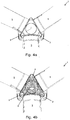
- Figs. 4a and 4b illustrate a front view of the horizontal axis wind turbine 1 of Fig. 1 .
- Fig. 4a illustrates the spinner 6 from the outside, whereas Fig. 4b provides a view through the spinner 6 to the hub 4 covered by the spinner 6 thereby providing a view to the service personnel 8 working in the space 7.
- Fig. 5 illustrates a front view of a horizontal axis wind turbine 1 which is parked with one of the blades 5 in a substantially horizontal position.
- the two other blades are not illustrated. Parking of the rotor so that one of the blades 5 is substantially horizontally positioned, the service personnel 8 may maintain and/or carry out repair work at an interface between a blade 5 and the hub 4, here at the blade flange 10.
- the wind turbine 1 is provided with three service floors 9, the number being equal to the number of blades 5, whereby a service floor 9 is provided when the rotor is parked with anyone of the blades 5 being substantially horizontally positioned.
- Fig. 6 illustrates a top view of a horizontal axis wind turbine 1 being parked with one of the blades pointing downwards. The two other blades pointing partly upwards and partly outwards have been removed to provide a view to the space 7.
- the nacelle 3 comprises a nacelle end wall 3a facing the spinner 6, and the spinner 6 comprise a spinner end wall facing the nacelle. Furthermore, the nacelle end wall 3a comprises at least two nacelle openings (not shown), and the spinner end wall comprise at least two spinner openings (not shown), so that, when the rotor is parked with anyone of the blades 5 pointing downwards, two nacelle opening are each aligned with a spinner opening, to provide two simultaneously appearing passages 13 from the nacelle 3 into the spinner 6.
- the distance between the nacelle end wall 3a and the spinner end wall is in the range of 50-90 millimetres, thereby ensuring that service personnel who has to enter the space 7 from the nacelle 3 are not exposed to the risk of falling down between the nacelle 3 and the spinner 6.
- the passages 13 are in the illustrated embodiment provided on opposite sides of the hub 4, i.e. on opposite sides of the rotor axis.
- the service floor 9 extends from one of the passages 13 to the other one of the passages 13, thereby providing the possibility of support for the service personnel 8 at a larger area of the space. Service personnel 8 thereby have the possibility of working at a larger area, i.e. from one passage 13 to the other passage 13 along the dotted line 14.
Landscapes
- Engineering & Computer Science (AREA)
- Life Sciences & Earth Sciences (AREA)
- Sustainable Development (AREA)
- Sustainable Energy (AREA)
- Chemical & Material Sciences (AREA)
- Combustion & Propulsion (AREA)
- Mechanical Engineering (AREA)
- General Engineering & Computer Science (AREA)
- Wind Motors (AREA)
Claims (13)
- Eolienne à axe horizontal (1) comprenant une tour (2), une nacelle (3) montée au sommet de la tour (2) et un rotor monté en rotation sur la nacelle (3), le rotor comprenant un moyeu (4) portant une pluralité de pales (5), dans laquelle chaque pale (5) est fixée audit moyeu (4) par le biais d'une bride de pale (10), et comprenant en outre un carénage (6), recouvrant le moyeu (4) et définissant un espace (7) entre le carénage (6) et le moyeu (4), le carénage (6) et le moyeu (4) sont dimensionnés de sorte que l'espace (7) permette au personnel technique de travailler dans l'espace (7), et en ce qu'un plancher technique (9) pour supporter le personnel technique est fourni dans l'espace (7), le plancher technique (9) fournissant une structure de support sensiblement plane (9'), caractérisée en ce que ladite éolienne à axe horizontal comprend, pour chaque pale (5) qui est portée par le moyeu (4), une dite structure de support sensiblement plane (9') qui est parallèle à une bride de pale (10), et dans laquelle le carénage (6) est formé par la pluralité de structures de support sensiblement planes (9') et une pluralité de parties intermédiaires s'étendant entre les structures de support planes (9').
- Eolienne selon la revendication 1, dans laquelle le carénage (6) et le moyeu (4) sont dimensionnés pour permettre au personnel technique de se tenir droit au moins dans certaines zones, en fournissant ainsi un espace présentant une hauteur d'au moins 1,75 mètre.
- Eolienne selon la revendication 1, dans laquelle le plancher technique (9) fait partie du carénage (6) et fait partie du, ou est fixé au, moyeu (4).
- Eolienne à axe horizontal selon l'une quelconque des revendications précédentes, dans laquelle le personnel technique peut se tenir droit au moins à certaines positions du plancher technique (9).
- Eolienne à axe horizontal selon l'une quelconque des revendications précédentes, dans laquelle le plancher technique (9) entoure au moins en partie une bride de pale (10).
- Eolienne à axe horizontal selon l'une quelconque des revendications précédentes et comprenant trois pales (5), dans laquelle ledit carénage (6) a une forme de type tétraèdre avec quatre faces triangulaires qui sont jointes.
- Eolienne à axe horizontal selon la revendication 6, dans laquelle une desdites faces triangulaires est tournée vers ladite nacelle (3), dans laquelle un arbre principal relié audit moyeu (4) s'étend depuis cette face, et dans laquelle les trois autres faces triangulaires sont tournées chacune dans la direction de l'une correspondante des pales (5), dans laquelle lesdites trois faces triangulaires définissent chacune un plancher technique (9), et elles sont jointes avec les deux autres faces par des parties intermédiaires courbées.
- Eolienne à axe horizontal selon l'une quelconque des revendications précédentes, dans laquelle la nacelle (3) comprend une paroi d'extrémité de nacelle (3a) tournée vers le carénage (6), et le carénage (6) comprend une paroi d'extrémité de carénage tournée vers la nacelle (3), et dans laquelle la paroi d'extrémité de nacelle (3a) comprend deux ouvertures de nacelle, et la paroi d'extrémité de carénage comprend au moins deux ouvertures de carénage, dans laquelle, lorsque le rotor est installé avec l'une quelconque des pales (5) dirigées vers le bas, les ouvertures de nacelle sont chacune alignées avec l'une des ouvertures de carénage, de sorte à fournir deux passages apparaissant simultanément (13) de la nacelle (3) jusque dans le carénage (6).
- Eolienne à axe horizontal selon la revendication 8, dans laquelle les passages (13) sont fournis sur des côtés opposés au moyeu (4).
- Eolienne à axe horizontal selon la revendication 9, dans laquelle chaque passage (13) est formé par une ouverture de nacelle et une ouverture de carénage correspondante.
- Eolienne à axe horizontal selon l'une quelconque des revendications 8 à 9, dans laquelle le plancher technique (9) s'étend depuis l'un des passages (13) à l'autre des passages (13).
- Eolienne à axe horizontal selon l'une quelconque des revendications précédentes, dans laquelle le plancher technique (9) fournit un support, lorsque le rotor est installé de sorte qu'une pale (5) soit dirigée vers le bas.
- Eolienne à axe horizontal selon l'une quelconque des revendications 1 à 10, comprenant en outre un plancher technique extérieur fourni sur une surface extérieure du carénage lorsque le rotor est installé avec l'une quelconque des pales dirigées vers le haut.
Priority Applications (2)
| Application Number | Priority Date | Filing Date | Title |
|---|---|---|---|
| EP16185407.0A EP3139035B1 (fr) | 2012-10-19 | 2013-10-18 | Éolienne comprenant un plancher de service |
| DK16185407.0T DK3139035T3 (en) | 2012-10-19 | 2013-10-18 | A WINDMILL COVERING A TECHNIQUE TAKE |
Applications Claiming Priority (4)
| Application Number | Priority Date | Filing Date | Title |
|---|---|---|---|
| DKPA201200643 | 2012-10-19 | ||
| US201261719601P | 2012-10-29 | 2012-10-29 | |
| GB1303608.2A GB2511341A (en) | 2013-02-28 | 2013-02-28 | A wind turbine comprising a service floor |
| PCT/DK2013/050335 WO2014059996A1 (fr) | 2012-10-19 | 2013-10-18 | Eolienne comprenant un plancher technique |
Related Child Applications (2)
| Application Number | Title | Priority Date | Filing Date |
|---|---|---|---|
| EP16185407.0A Division EP3139035B1 (fr) | 2012-10-19 | 2013-10-18 | Éolienne comprenant un plancher de service |
| EP16185407.0A Division-Into EP3139035B1 (fr) | 2012-10-19 | 2013-10-18 | Éolienne comprenant un plancher de service |
Publications (2)
| Publication Number | Publication Date |
|---|---|
| EP2909471A1 EP2909471A1 (fr) | 2015-08-26 |
| EP2909471B1 true EP2909471B1 (fr) | 2016-10-05 |
Family
ID=50487591
Family Applications (2)
| Application Number | Title | Priority Date | Filing Date |
|---|---|---|---|
| EP13782950.3A Active EP2909471B1 (fr) | 2012-10-19 | 2013-10-18 | Eolienne comprenant un plancher technique |
| EP16185407.0A Active EP3139035B1 (fr) | 2012-10-19 | 2013-10-18 | Éolienne comprenant un plancher de service |
Family Applications After (1)
| Application Number | Title | Priority Date | Filing Date |
|---|---|---|---|
| EP16185407.0A Active EP3139035B1 (fr) | 2012-10-19 | 2013-10-18 | Éolienne comprenant un plancher de service |
Country Status (5)
| Country | Link |
|---|---|
| US (1) | US10260478B2 (fr) |
| EP (2) | EP2909471B1 (fr) |
| CN (1) | CN104870807B (fr) |
| DK (2) | DK3139035T3 (fr) |
| WO (1) | WO2014059996A1 (fr) |
Families Citing this family (5)
| Publication number | Priority date | Publication date | Assignee | Title |
|---|---|---|---|---|
| ES2790673T3 (es) | 2014-09-23 | 2020-10-28 | Nordex Energy Gmbh | Casquete para un cubo de rotor |
| DK3139033T3 (da) | 2015-09-07 | 2019-05-20 | Siemens Gamesa Renewable Energy As | Vedligeholdelsesadgang til vingeleje af vindmølle |
| US10570888B2 (en) * | 2017-04-27 | 2020-02-25 | General Electric Company | Working platform within a nacelle of a wind turbine |
| WO2019034220A1 (fr) * | 2017-08-15 | 2019-02-21 | Envision Energy (Denmark) Aps | Système de moyeu pour une éolienne |
| DE102018120810A1 (de) * | 2018-08-27 | 2020-02-27 | Renk Aktiengesellschaft | Lageranordnung eines Rotors einer Windkraftanlage und Windkraftanlage |
Family Cites Families (13)
| Publication number | Priority date | Publication date | Assignee | Title |
|---|---|---|---|---|
| US8089373B2 (en) * | 2006-07-26 | 2012-01-03 | Beale Harry A | Sign system for roads |
| JP4865506B2 (ja) * | 2006-10-31 | 2012-02-01 | 三菱重工業株式会社 | 歯車の歯合わせ角度検出方法及び装置 |
| US7857599B2 (en) | 2007-01-10 | 2010-12-28 | General Electric Company | Method and apparatus for forming wind turbine machines |
| US8186940B2 (en) * | 2007-09-05 | 2012-05-29 | General Electric Company | Ventilation arrangement |
| US8061999B2 (en) * | 2008-11-21 | 2011-11-22 | General Electric Company | Spinner-less hub access and lifting system for a wind turbine |
| WO2010102967A2 (fr) * | 2009-03-13 | 2010-09-16 | Vestas Wind Systems A/S | Verrou de rotor pour éolienne |
| ES2359310B2 (es) * | 2009-11-10 | 2012-05-16 | Gamesa Innovation & Technology S.L. | Aerogenerador con v�?as internas de acceso mejoradas. |
| US8619477B2 (en) * | 2010-07-20 | 2013-12-31 | Taiwan Semiconductor Manufacturing Company, Ltd. | Two-port SRAM write tracking scheme |
| BRPI1100020A2 (pt) | 2011-01-28 | 2016-05-03 | Mitsubishi Heavy Ind Ltd | gerador de turbina eólica. |
| GB2487797A (en) * | 2011-02-07 | 2012-08-08 | Vestas Wind Sys As | Wind turbine rotor service platform |
| US8449263B2 (en) * | 2011-12-07 | 2013-05-28 | General Electric Company | Segmented rotor hub assembly |
| US9115698B2 (en) * | 2012-03-06 | 2015-08-25 | General Electric Company | Wind turbine with access features for gaining access to the interior of a rotor hub |
| EP2662559A1 (fr) * | 2012-05-09 | 2013-11-13 | Siemens Aktiengesellschaft | Éolienne |
-
2013
- 2013-10-18 WO PCT/DK2013/050335 patent/WO2014059996A1/fr active Application Filing
- 2013-10-18 EP EP13782950.3A patent/EP2909471B1/fr active Active
- 2013-10-18 DK DK16185407.0T patent/DK3139035T3/en active
- 2013-10-18 CN CN201380066351.6A patent/CN104870807B/zh not_active Expired - Fee Related
- 2013-10-18 EP EP16185407.0A patent/EP3139035B1/fr active Active
- 2013-10-18 US US14/437,129 patent/US10260478B2/en active Active
- 2013-10-18 DK DK13782950.3T patent/DK2909471T3/en active
Also Published As
| Publication number | Publication date |
|---|---|
| EP3139035A1 (fr) | 2017-03-08 |
| CN104870807A (zh) | 2015-08-26 |
| CN104870807B (zh) | 2017-06-30 |
| US10260478B2 (en) | 2019-04-16 |
| EP3139035B1 (fr) | 2018-05-02 |
| EP2909471A1 (fr) | 2015-08-26 |
| WO2014059996A1 (fr) | 2014-04-24 |
| DK2909471T3 (en) | 2016-12-05 |
| US20150285218A1 (en) | 2015-10-08 |
| DK3139035T3 (en) | 2018-06-14 |
Similar Documents
| Publication | Publication Date | Title |
|---|---|---|
| EP2909471B1 (fr) | Eolienne comprenant un plancher technique | |
| US10125745B2 (en) | Nacelle construction for a wind turbine | |
| US9394887B2 (en) | Wind turbine nacelle | |
| RU2564734C2 (ru) | Ветровая энергетическая установка | |
| EP2620644B1 (fr) | Améliorations portant sur un ensemble d'éolienne | |
| EP2192297A2 (fr) | Système de levage et d'accès à moyeu sans spinner pour éolienne | |
| KR101699647B1 (ko) | 풍력 발전 설비 | |
| US20080166231A1 (en) | Method and apparatus for forming wind turbine machines | |
| CN106499575B (zh) | 到叶片轴承的维护通道 | |
| US20150078914A1 (en) | Access system for a hub of a wind turbine | |
| TW201905329A (zh) | 具有拉線之多轉子風力渦輪機 | |
| US10641042B2 (en) | External ladder assembly for wind turbine nacelle | |
| GB2511341A (en) | A wind turbine comprising a service floor | |
| EP3431757B1 (fr) | Ensemble plateforme externe pour réparation d'éolienne | |
| CA2896561C (fr) | Systeme de turbines eoliennes equipe d'une console de tour | |
| KR101767545B1 (ko) | 유지보수용 개구가 마련된 중공형 메인 샤프트를 구비하는 풍력 발전기 | |
| CN209855953U (zh) | 风力涡轮机的轮毂系统 | |
| NZ625331B2 (en) | Wind turbine nacelle |
Legal Events
| Date | Code | Title | Description |
|---|---|---|---|
| PUAI | Public reference made under article 153(3) epc to a published international application that has entered the european phase |
Free format text: ORIGINAL CODE: 0009012 |
|
| 17P | Request for examination filed |
Effective date: 20150428 |
|
| AK | Designated contracting states |
Kind code of ref document: A1 Designated state(s): AL AT BE BG CH CY CZ DE DK EE ES FI FR GB GR HR HU IE IS IT LI LT LU LV MC MK MT NL NO PL PT RO RS SE SI SK SM TR |
|
| AX | Request for extension of the european patent |
Extension state: BA ME |
|
| DAX | Request for extension of the european patent (deleted) | ||
| GRAP | Despatch of communication of intention to grant a patent |
Free format text: ORIGINAL CODE: EPIDOSNIGR1 |
|
| INTG | Intention to grant announced |
Effective date: 20160425 |
|
| GRAS | Grant fee paid |
Free format text: ORIGINAL CODE: EPIDOSNIGR3 |
|
| GRAA | (expected) grant |
Free format text: ORIGINAL CODE: 0009210 |
|
| AK | Designated contracting states |
Kind code of ref document: B1 Designated state(s): AL AT BE BG CH CY CZ DE DK EE ES FI FR GB GR HR HU IE IS IT LI LT LU LV MC MK MT NL NO PL PT RO RS SE SI SK SM TR |
|
| REG | Reference to a national code |
Ref country code: GB Ref legal event code: FG4D |
|
| REG | Reference to a national code |
Ref country code: CH Ref legal event code: EP |
|
| REG | Reference to a national code |
Ref country code: AT Ref legal event code: REF Ref document number: 834901 Country of ref document: AT Kind code of ref document: T Effective date: 20161015 |
|
| REG | Reference to a national code |
Ref country code: IE Ref legal event code: FG4D |
|
| REG | Reference to a national code |
Ref country code: FR Ref legal event code: PLFP Year of fee payment: 4 |
|
| REG | Reference to a national code |
Ref country code: DE Ref legal event code: R096 Ref document number: 602013012515 Country of ref document: DE |
|
| REG | Reference to a national code |
Ref country code: DK Ref legal event code: T3 Effective date: 20161128 |
|
| REG | Reference to a national code |
Ref country code: NL Ref legal event code: MP Effective date: 20161005 |
|
| REG | Reference to a national code |
Ref country code: LT Ref legal event code: MG4D |
|
| PG25 | Lapsed in a contracting state [announced via postgrant information from national office to epo] |
Ref country code: LV Free format text: LAPSE BECAUSE OF FAILURE TO SUBMIT A TRANSLATION OF THE DESCRIPTION OR TO PAY THE FEE WITHIN THE PRESCRIBED TIME-LIMIT Effective date: 20161005 Ref country code: BE Free format text: LAPSE BECAUSE OF NON-PAYMENT OF DUE FEES Effective date: 20161031 |
|
| REG | Reference to a national code |
Ref country code: AT Ref legal event code: MK05 Ref document number: 834901 Country of ref document: AT Kind code of ref document: T Effective date: 20161005 |
|
| PG25 | Lapsed in a contracting state [announced via postgrant information from national office to epo] |
Ref country code: GR Free format text: LAPSE BECAUSE OF FAILURE TO SUBMIT A TRANSLATION OF THE DESCRIPTION OR TO PAY THE FEE WITHIN THE PRESCRIBED TIME-LIMIT Effective date: 20170106 Ref country code: SE Free format text: LAPSE BECAUSE OF FAILURE TO SUBMIT A TRANSLATION OF THE DESCRIPTION OR TO PAY THE FEE WITHIN THE PRESCRIBED TIME-LIMIT Effective date: 20161005 Ref country code: LT Free format text: LAPSE BECAUSE OF FAILURE TO SUBMIT A TRANSLATION OF THE DESCRIPTION OR TO PAY THE FEE WITHIN THE PRESCRIBED TIME-LIMIT Effective date: 20161005 Ref country code: NO Free format text: LAPSE BECAUSE OF FAILURE TO SUBMIT A TRANSLATION OF THE DESCRIPTION OR TO PAY THE FEE WITHIN THE PRESCRIBED TIME-LIMIT Effective date: 20170105 |
|
| PG25 | Lapsed in a contracting state [announced via postgrant information from national office to epo] |
Ref country code: PT Free format text: LAPSE BECAUSE OF FAILURE TO SUBMIT A TRANSLATION OF THE DESCRIPTION OR TO PAY THE FEE WITHIN THE PRESCRIBED TIME-LIMIT Effective date: 20170206 Ref country code: IS Free format text: LAPSE BECAUSE OF FAILURE TO SUBMIT A TRANSLATION OF THE DESCRIPTION OR TO PAY THE FEE WITHIN THE PRESCRIBED TIME-LIMIT Effective date: 20170205 Ref country code: HR Free format text: LAPSE BECAUSE OF FAILURE TO SUBMIT A TRANSLATION OF THE DESCRIPTION OR TO PAY THE FEE WITHIN THE PRESCRIBED TIME-LIMIT Effective date: 20161005 Ref country code: FI Free format text: LAPSE BECAUSE OF FAILURE TO SUBMIT A TRANSLATION OF THE DESCRIPTION OR TO PAY THE FEE WITHIN THE PRESCRIBED TIME-LIMIT Effective date: 20161005 Ref country code: PL Free format text: LAPSE BECAUSE OF FAILURE TO SUBMIT A TRANSLATION OF THE DESCRIPTION OR TO PAY THE FEE WITHIN THE PRESCRIBED TIME-LIMIT Effective date: 20161005 Ref country code: ES Free format text: LAPSE BECAUSE OF FAILURE TO SUBMIT A TRANSLATION OF THE DESCRIPTION OR TO PAY THE FEE WITHIN THE PRESCRIBED TIME-LIMIT Effective date: 20161005 Ref country code: RS Free format text: LAPSE BECAUSE OF FAILURE TO SUBMIT A TRANSLATION OF THE DESCRIPTION OR TO PAY THE FEE WITHIN THE PRESCRIBED TIME-LIMIT Effective date: 20161005 Ref country code: BE Free format text: LAPSE BECAUSE OF FAILURE TO SUBMIT A TRANSLATION OF THE DESCRIPTION OR TO PAY THE FEE WITHIN THE PRESCRIBED TIME-LIMIT Effective date: 20161005 Ref country code: NL Free format text: LAPSE BECAUSE OF FAILURE TO SUBMIT A TRANSLATION OF THE DESCRIPTION OR TO PAY THE FEE WITHIN THE PRESCRIBED TIME-LIMIT Effective date: 20161005 Ref country code: AT Free format text: LAPSE BECAUSE OF FAILURE TO SUBMIT A TRANSLATION OF THE DESCRIPTION OR TO PAY THE FEE WITHIN THE PRESCRIBED TIME-LIMIT Effective date: 20161005 |
|
| REG | Reference to a national code |
Ref country code: CH Ref legal event code: PL |
|
| REG | Reference to a national code |
Ref country code: DE Ref legal event code: R097 Ref document number: 602013012515 Country of ref document: DE |
|
| REG | Reference to a national code |
Ref country code: IE Ref legal event code: MM4A |
|
| PG25 | Lapsed in a contracting state [announced via postgrant information from national office to epo] |
Ref country code: SK Free format text: LAPSE BECAUSE OF FAILURE TO SUBMIT A TRANSLATION OF THE DESCRIPTION OR TO PAY THE FEE WITHIN THE PRESCRIBED TIME-LIMIT Effective date: 20161005 Ref country code: EE Free format text: LAPSE BECAUSE OF FAILURE TO SUBMIT A TRANSLATION OF THE DESCRIPTION OR TO PAY THE FEE WITHIN THE PRESCRIBED TIME-LIMIT Effective date: 20161005 Ref country code: CZ Free format text: LAPSE BECAUSE OF FAILURE TO SUBMIT A TRANSLATION OF THE DESCRIPTION OR TO PAY THE FEE WITHIN THE PRESCRIBED TIME-LIMIT Effective date: 20161005 Ref country code: MC Free format text: LAPSE BECAUSE OF FAILURE TO SUBMIT A TRANSLATION OF THE DESCRIPTION OR TO PAY THE FEE WITHIN THE PRESCRIBED TIME-LIMIT Effective date: 20161005 Ref country code: LI Free format text: LAPSE BECAUSE OF NON-PAYMENT OF DUE FEES Effective date: 20161031 Ref country code: CH Free format text: LAPSE BECAUSE OF NON-PAYMENT OF DUE FEES Effective date: 20161031 Ref country code: RO Free format text: LAPSE BECAUSE OF FAILURE TO SUBMIT A TRANSLATION OF THE DESCRIPTION OR TO PAY THE FEE WITHIN THE PRESCRIBED TIME-LIMIT Effective date: 20161005 |
|
| PLBE | No opposition filed within time limit |
Free format text: ORIGINAL CODE: 0009261 |
|
| STAA | Information on the status of an ep patent application or granted ep patent |
Free format text: STATUS: NO OPPOSITION FILED WITHIN TIME LIMIT |
|
| PG25 | Lapsed in a contracting state [announced via postgrant information from national office to epo] |
Ref country code: BG Free format text: LAPSE BECAUSE OF FAILURE TO SUBMIT A TRANSLATION OF THE DESCRIPTION OR TO PAY THE FEE WITHIN THE PRESCRIBED TIME-LIMIT Effective date: 20170105 Ref country code: SM Free format text: LAPSE BECAUSE OF FAILURE TO SUBMIT A TRANSLATION OF THE DESCRIPTION OR TO PAY THE FEE WITHIN THE PRESCRIBED TIME-LIMIT Effective date: 20161005 Ref country code: LU Free format text: LAPSE BECAUSE OF NON-PAYMENT OF DUE FEES Effective date: 20161018 Ref country code: IT Free format text: LAPSE BECAUSE OF FAILURE TO SUBMIT A TRANSLATION OF THE DESCRIPTION OR TO PAY THE FEE WITHIN THE PRESCRIBED TIME-LIMIT Effective date: 20161005 |
|
| 26N | No opposition filed |
Effective date: 20170706 |
|
| REG | Reference to a national code |
Ref country code: FR Ref legal event code: PLFP Year of fee payment: 5 |
|
| PG25 | Lapsed in a contracting state [announced via postgrant information from national office to epo] |
Ref country code: SI Free format text: LAPSE BECAUSE OF FAILURE TO SUBMIT A TRANSLATION OF THE DESCRIPTION OR TO PAY THE FEE WITHIN THE PRESCRIBED TIME-LIMIT Effective date: 20161005 Ref country code: IE Free format text: LAPSE BECAUSE OF NON-PAYMENT OF DUE FEES Effective date: 20161018 |
|
| PG25 | Lapsed in a contracting state [announced via postgrant information from national office to epo] |
Ref country code: HU Free format text: LAPSE BECAUSE OF FAILURE TO SUBMIT A TRANSLATION OF THE DESCRIPTION OR TO PAY THE FEE WITHIN THE PRESCRIBED TIME-LIMIT; INVALID AB INITIO Effective date: 20131018 |
|
| PG25 | Lapsed in a contracting state [announced via postgrant information from national office to epo] |
Ref country code: MT Free format text: LAPSE BECAUSE OF NON-PAYMENT OF DUE FEES Effective date: 20161031 Ref country code: MK Free format text: LAPSE BECAUSE OF FAILURE TO SUBMIT A TRANSLATION OF THE DESCRIPTION OR TO PAY THE FEE WITHIN THE PRESCRIBED TIME-LIMIT Effective date: 20161005 Ref country code: CY Free format text: LAPSE BECAUSE OF FAILURE TO SUBMIT A TRANSLATION OF THE DESCRIPTION OR TO PAY THE FEE WITHIN THE PRESCRIBED TIME-LIMIT Effective date: 20161005 |
|
| REG | Reference to a national code |
Ref country code: FR Ref legal event code: PLFP Year of fee payment: 6 |
|
| PG25 | Lapsed in a contracting state [announced via postgrant information from national office to epo] |
Ref country code: TR Free format text: LAPSE BECAUSE OF FAILURE TO SUBMIT A TRANSLATION OF THE DESCRIPTION OR TO PAY THE FEE WITHIN THE PRESCRIBED TIME-LIMIT Effective date: 20161005 |
|
| PG25 | Lapsed in a contracting state [announced via postgrant information from national office to epo] |
Ref country code: AL Free format text: LAPSE BECAUSE OF FAILURE TO SUBMIT A TRANSLATION OF THE DESCRIPTION OR TO PAY THE FEE WITHIN THE PRESCRIBED TIME-LIMIT Effective date: 20161005 |
|
| P01 | Opt-out of the competence of the unified patent court (upc) registered |
Effective date: 20230521 |
|
| PGFP | Annual fee paid to national office [announced via postgrant information from national office to epo] |
Ref country code: GB Payment date: 20231024 Year of fee payment: 11 |
|
| PGFP | Annual fee paid to national office [announced via postgrant information from national office to epo] |
Ref country code: FR Payment date: 20231026 Year of fee payment: 11 Ref country code: DK Payment date: 20231023 Year of fee payment: 11 Ref country code: DE Payment date: 20231027 Year of fee payment: 11 |