EP2909360B1 - Fatigue- resistant coating for metal forming members - Google Patents
Fatigue- resistant coating for metal forming members Download PDFInfo
- Publication number
- EP2909360B1 EP2909360B1 EP13849145.1A EP13849145A EP2909360B1 EP 2909360 B1 EP2909360 B1 EP 2909360B1 EP 13849145 A EP13849145 A EP 13849145A EP 2909360 B1 EP2909360 B1 EP 2909360B1
- Authority
- EP
- European Patent Office
- Prior art keywords
- layer
- metal forming
- dopant
- range
- forming member
- Prior art date
- Legal status (The legal status is an assumption and is not a legal conclusion. Google has not performed a legal analysis and makes no representation as to the accuracy of the status listed.)
- Active
Links
Images


Classifications
-
- C—CHEMISTRY; METALLURGY
- C23—COATING METALLIC MATERIAL; COATING MATERIAL WITH METALLIC MATERIAL; CHEMICAL SURFACE TREATMENT; DIFFUSION TREATMENT OF METALLIC MATERIAL; COATING BY VACUUM EVAPORATION, BY SPUTTERING, BY ION IMPLANTATION OR BY CHEMICAL VAPOUR DEPOSITION, IN GENERAL; INHIBITING CORROSION OF METALLIC MATERIAL OR INCRUSTATION IN GENERAL
- C23C—COATING METALLIC MATERIAL; COATING MATERIAL WITH METALLIC MATERIAL; SURFACE TREATMENT OF METALLIC MATERIAL BY DIFFUSION INTO THE SURFACE, BY CHEMICAL CONVERSION OR SUBSTITUTION; COATING BY VACUUM EVAPORATION, BY SPUTTERING, BY ION IMPLANTATION OR BY CHEMICAL VAPOUR DEPOSITION, IN GENERAL
- C23C16/00—Chemical coating by decomposition of gaseous compounds, without leaving reaction products of surface material in the coating, i.e. chemical vapour deposition [CVD] processes
- C23C16/44—Chemical coating by decomposition of gaseous compounds, without leaving reaction products of surface material in the coating, i.e. chemical vapour deposition [CVD] processes characterised by the method of coating
- C23C16/50—Chemical coating by decomposition of gaseous compounds, without leaving reaction products of surface material in the coating, i.e. chemical vapour deposition [CVD] processes characterised by the method of coating using electric discharges
-
- C—CHEMISTRY; METALLURGY
- C23—COATING METALLIC MATERIAL; COATING MATERIAL WITH METALLIC MATERIAL; CHEMICAL SURFACE TREATMENT; DIFFUSION TREATMENT OF METALLIC MATERIAL; COATING BY VACUUM EVAPORATION, BY SPUTTERING, BY ION IMPLANTATION OR BY CHEMICAL VAPOUR DEPOSITION, IN GENERAL; INHIBITING CORROSION OF METALLIC MATERIAL OR INCRUSTATION IN GENERAL
- C23C—COATING METALLIC MATERIAL; COATING MATERIAL WITH METALLIC MATERIAL; SURFACE TREATMENT OF METALLIC MATERIAL BY DIFFUSION INTO THE SURFACE, BY CHEMICAL CONVERSION OR SUBSTITUTION; COATING BY VACUUM EVAPORATION, BY SPUTTERING, BY ION IMPLANTATION OR BY CHEMICAL VAPOUR DEPOSITION, IN GENERAL
- C23C14/00—Coating by vacuum evaporation, by sputtering or by ion implantation of the coating forming material
- C23C14/06—Coating by vacuum evaporation, by sputtering or by ion implantation of the coating forming material characterised by the coating material
- C23C14/0641—Nitrides
-
- B—PERFORMING OPERATIONS; TRANSPORTING
- B21—MECHANICAL METAL-WORKING WITHOUT ESSENTIALLY REMOVING MATERIAL; PUNCHING METAL
- B21D—WORKING OR PROCESSING OF SHEET METAL OR METAL TUBES, RODS OR PROFILES WITHOUT ESSENTIALLY REMOVING MATERIAL; PUNCHING METAL
- B21D37/00—Tools as parts of machines covered by this subclass
-
- B—PERFORMING OPERATIONS; TRANSPORTING
- B21—MECHANICAL METAL-WORKING WITHOUT ESSENTIALLY REMOVING MATERIAL; PUNCHING METAL
- B21D—WORKING OR PROCESSING OF SHEET METAL OR METAL TUBES, RODS OR PROFILES WITHOUT ESSENTIALLY REMOVING MATERIAL; PUNCHING METAL
- B21D37/00—Tools as parts of machines covered by this subclass
- B21D37/01—Selection of materials
-
- C—CHEMISTRY; METALLURGY
- C23—COATING METALLIC MATERIAL; COATING MATERIAL WITH METALLIC MATERIAL; CHEMICAL SURFACE TREATMENT; DIFFUSION TREATMENT OF METALLIC MATERIAL; COATING BY VACUUM EVAPORATION, BY SPUTTERING, BY ION IMPLANTATION OR BY CHEMICAL VAPOUR DEPOSITION, IN GENERAL; INHIBITING CORROSION OF METALLIC MATERIAL OR INCRUSTATION IN GENERAL
- C23C—COATING METALLIC MATERIAL; COATING MATERIAL WITH METALLIC MATERIAL; SURFACE TREATMENT OF METALLIC MATERIAL BY DIFFUSION INTO THE SURFACE, BY CHEMICAL CONVERSION OR SUBSTITUTION; COATING BY VACUUM EVAPORATION, BY SPUTTERING, BY ION IMPLANTATION OR BY CHEMICAL VAPOUR DEPOSITION, IN GENERAL
- C23C14/00—Coating by vacuum evaporation, by sputtering or by ion implantation of the coating forming material
- C23C14/58—After-treatment
- C23C14/5846—Reactive treatment
-
- C—CHEMISTRY; METALLURGY
- C23—COATING METALLIC MATERIAL; COATING MATERIAL WITH METALLIC MATERIAL; CHEMICAL SURFACE TREATMENT; DIFFUSION TREATMENT OF METALLIC MATERIAL; COATING BY VACUUM EVAPORATION, BY SPUTTERING, BY ION IMPLANTATION OR BY CHEMICAL VAPOUR DEPOSITION, IN GENERAL; INHIBITING CORROSION OF METALLIC MATERIAL OR INCRUSTATION IN GENERAL
- C23C—COATING METALLIC MATERIAL; COATING MATERIAL WITH METALLIC MATERIAL; SURFACE TREATMENT OF METALLIC MATERIAL BY DIFFUSION INTO THE SURFACE, BY CHEMICAL CONVERSION OR SUBSTITUTION; COATING BY VACUUM EVAPORATION, BY SPUTTERING, BY ION IMPLANTATION OR BY CHEMICAL VAPOUR DEPOSITION, IN GENERAL
- C23C16/00—Chemical coating by decomposition of gaseous compounds, without leaving reaction products of surface material in the coating, i.e. chemical vapour deposition [CVD] processes
- C23C16/06—Chemical coating by decomposition of gaseous compounds, without leaving reaction products of surface material in the coating, i.e. chemical vapour deposition [CVD] processes characterised by the deposition of metallic material
-
- C—CHEMISTRY; METALLURGY
- C23—COATING METALLIC MATERIAL; COATING MATERIAL WITH METALLIC MATERIAL; CHEMICAL SURFACE TREATMENT; DIFFUSION TREATMENT OF METALLIC MATERIAL; COATING BY VACUUM EVAPORATION, BY SPUTTERING, BY ION IMPLANTATION OR BY CHEMICAL VAPOUR DEPOSITION, IN GENERAL; INHIBITING CORROSION OF METALLIC MATERIAL OR INCRUSTATION IN GENERAL
- C23C—COATING METALLIC MATERIAL; COATING MATERIAL WITH METALLIC MATERIAL; SURFACE TREATMENT OF METALLIC MATERIAL BY DIFFUSION INTO THE SURFACE, BY CHEMICAL CONVERSION OR SUBSTITUTION; COATING BY VACUUM EVAPORATION, BY SPUTTERING, BY ION IMPLANTATION OR BY CHEMICAL VAPOUR DEPOSITION, IN GENERAL
- C23C28/00—Coating for obtaining at least two superposed coatings either by methods not provided for in a single one of groups C23C2/00 - C23C26/00 or by combinations of methods provided for in subclasses C23C and C25C or C25D
- C23C28/04—Coating for obtaining at least two superposed coatings either by methods not provided for in a single one of groups C23C2/00 - C23C26/00 or by combinations of methods provided for in subclasses C23C and C25C or C25D only coatings of inorganic non-metallic material
- C23C28/042—Coating for obtaining at least two superposed coatings either by methods not provided for in a single one of groups C23C2/00 - C23C26/00 or by combinations of methods provided for in subclasses C23C and C25C or C25D only coatings of inorganic non-metallic material including a refractory ceramic layer, e.g. refractory metal oxides, ZrO2, rare earth oxides
-
- C—CHEMISTRY; METALLURGY
- C23—COATING METALLIC MATERIAL; COATING MATERIAL WITH METALLIC MATERIAL; CHEMICAL SURFACE TREATMENT; DIFFUSION TREATMENT OF METALLIC MATERIAL; COATING BY VACUUM EVAPORATION, BY SPUTTERING, BY ION IMPLANTATION OR BY CHEMICAL VAPOUR DEPOSITION, IN GENERAL; INHIBITING CORROSION OF METALLIC MATERIAL OR INCRUSTATION IN GENERAL
- C23C—COATING METALLIC MATERIAL; COATING MATERIAL WITH METALLIC MATERIAL; SURFACE TREATMENT OF METALLIC MATERIAL BY DIFFUSION INTO THE SURFACE, BY CHEMICAL CONVERSION OR SUBSTITUTION; COATING BY VACUUM EVAPORATION, BY SPUTTERING, BY ION IMPLANTATION OR BY CHEMICAL VAPOUR DEPOSITION, IN GENERAL
- C23C28/00—Coating for obtaining at least two superposed coatings either by methods not provided for in a single one of groups C23C2/00 - C23C26/00 or by combinations of methods provided for in subclasses C23C and C25C or C25D
- C23C28/04—Coating for obtaining at least two superposed coatings either by methods not provided for in a single one of groups C23C2/00 - C23C26/00 or by combinations of methods provided for in subclasses C23C and C25C or C25D only coatings of inorganic non-metallic material
- C23C28/044—Coating for obtaining at least two superposed coatings either by methods not provided for in a single one of groups C23C2/00 - C23C26/00 or by combinations of methods provided for in subclasses C23C and C25C or C25D only coatings of inorganic non-metallic material coatings specially adapted for cutting tools or wear applications
-
- Y—GENERAL TAGGING OF NEW TECHNOLOGICAL DEVELOPMENTS; GENERAL TAGGING OF CROSS-SECTIONAL TECHNOLOGIES SPANNING OVER SEVERAL SECTIONS OF THE IPC; TECHNICAL SUBJECTS COVERED BY FORMER USPC CROSS-REFERENCE ART COLLECTIONS [XRACs] AND DIGESTS
- Y10—TECHNICAL SUBJECTS COVERED BY FORMER USPC
- Y10T—TECHNICAL SUBJECTS COVERED BY FORMER US CLASSIFICATION
- Y10T428/00—Stock material or miscellaneous articles
- Y10T428/26—Web or sheet containing structurally defined element or component, the element or component having a specified physical dimension
- Y10T428/263—Coating layer not in excess of 5 mils thick or equivalent
- Y10T428/264—Up to 3 mils
- Y10T428/265—1 mil or less
-
- Y—GENERAL TAGGING OF NEW TECHNOLOGICAL DEVELOPMENTS; GENERAL TAGGING OF CROSS-SECTIONAL TECHNOLOGIES SPANNING OVER SEVERAL SECTIONS OF THE IPC; TECHNICAL SUBJECTS COVERED BY FORMER USPC CROSS-REFERENCE ART COLLECTIONS [XRACs] AND DIGESTS
- Y10—TECHNICAL SUBJECTS COVERED BY FORMER USPC
- Y10T—TECHNICAL SUBJECTS COVERED BY FORMER US CLASSIFICATION
- Y10T428/00—Stock material or miscellaneous articles
- Y10T428/31504—Composite [nonstructural laminate]
- Y10T428/31678—Of metal
Definitions
- the present disclosure relates generally to tools and dies used in metal forming applications. More specifically, the disclosure relates to a fatigue-, wear-, and friction-resistant composite coating, and to metal forming members having that coating disposed on their surface.
- AHSS advanced high strength steel alloys
- Typical AHSS alloys manifest tensile strengths which exceed 700 MPa.
- alloys having tensile strengths in the range of 900-1200 MPa are employed in the fabrication of structural components for automobiles and the like.
- AHSS steels are very difficult to form and dies used for their forming are exposed to high impact and high pressure conditions.
- the surfaces of the dies experience very high frictional forces in use.
- the prior art has sought to harden the surfaces of the dies by various treatment processes; however, these results have produced only limited success.
- dies have been coated with various high hardness, wear resistant coatings including titanium nitride, titanium carbonitride, chromium nitride, titanium aluminum nitride, and the like.
- thermal diffusion coatings of materials such as vanadium carbide and chemical vapor deposition (CVD) coatings such as titanium carbide have been utilized. While each of these surface enhancement techniques have demonstrated success in extending the service life of dies used to form conventional alloys having strength levels below 400 MPa, they all manifest poor performance in forming operations involving AHSS alloys.
- thermal diffusion and CVD coatings have been found to extend the service life of dies used for forming AHSS alloys.
- both of these processes tend to produce changes in the dimensions of the dies resultant from changes in crystal structure during the deposition and heat treatment of commonly used tool steel die materials. The magnitude of these dimensional changes is very often outside the dimensional specifications defined by the users of the forming dies; hence, such processes are generally not acceptable.
- thermal diffusion coatings have relatively high coefficients of friction and are incompatible with the high levels of frictional forces generated in the forming of high tensile strength AHSS materials.
- PVD coatings unlike CVD coatings and thermal diffusion coatings, do not cause unacceptable dimensional changes to the forming dies, many of such coatings have other limitations which restrict their use in high tensile strength material forming applications. Because of their columnar structure, PVD coatings such as chromium nitride, titanium aluminum nitride, and the like are susceptible to cracking when subjected to high pressure/impact conditions such as those found in the forming of materials having tensile strengths greater than 400 MPa. Some increase in die performance has been achieved by case hardening the surfaces of the dies prior to coating with conventional PVD coatings since the increased surface hardness of the die prevents deformation and cracking of the coating.
- EP 1 245 699 A2 relates to a coated tool for warm and/or hot working with good galling resistance property and wear resistance.
- the coated tool comprises a base material selected from the group consisting of a hot die steel and a high speed steel and a coating as a working surface, the coating having: a layer “a” provided on said base material, the layer “a” being made of at least one kind selected from the group consisting of a nitride, a carbide and a carbonitride, each of which contains as the main constituent thereof at least one metal element selected from the group consisting of Ti, V, Cr, Al and Si and a layer "b" provided on the layer "a", the layer "b” being made of a sulfide.
- the present disclosure provides for a composite coating for a metal forming member.
- the coating includes a metal forming member and a first layer disposed on the metal forming member.
- the first layer includes chromium nitride doped with at least one dopant, wherein said dopant is selected from the group consisting of one or more of: W, V, Ti, Zr, Co, Mo, and Ta.
- a second layer is disposed atop the first layer, wherein said second layer comprises at least one material selected from the group of nitrides, carbonitrides, oxides, oxynitrides, carbon based coatings, molybdenum based solid film lubricant coatings, and combinations thereof.
- the second layer includes a lubricious material having optionally a coefficient of friction of less than or equal to 0.2 as measured against low alloy steel.
- the dopant is selected from the group consisting of one or more of: W, V, Ti, Zr, Co, Mo, and Ta. In an example, the dopant is W.
- the dopant can be present in a range of 1 to 10 atomic percent, such as a range of 3 to 7 atomic percent, and in particular instances said dopant is present in and amount of approximately 5 atomic percent.
- the thickness of the first layer can be in the range of 1 to 10 micrometers, such as a range of 4 to 6 micrometers.
- the hardness of the first layer can be in the range of 2 to 5 KHv, such as 3 to 4 KHv, and in particular instances 3.6 to 3.8 KHv.
- the second layer has a coefficient of friction in the range of 0.1 to 0.15 as measured against low alloy steel.
- the thickness of the second layer can be in the range of 0.5 to 5 micrometers, and in particular instances 1.2 micrometers.
- the second layer includes at least one material selected from the group of nitrides, carbonitrides, oxides, oxynitrides, carbon based coatings, molybdenum based solid film lubricant coatings, and combinations thereof.
- the second layer comprises TiCN.
- the present disclosure further provides for a metal forming member including the composite coating of any of those described herein.
- the metal forming member can include a die.
- the present disclosure further provides for a method of coating a metal forming member including applying the composite coating of any one of the previously described coatings thereto. At least one of the layers of the composite coating may be applied by a plasma vapor deposition process.
- the present disclosure provides for a method of forming a body of an advanced high strength steel. The method including the use of the metal forming member as described herein.
- the advanced high strength steel can have a tensile strength of at least 700 MPa, such as a strength of at least 900 MPa, and in particular instances a strength of at least 1000 MPa.
- the present disclosure is directed to a composite coating for a metal forming member such as a die or the like.
- the coating is disposed on at least a forming surface of a metalworking member and comprises a first layer of a doped chromium nitride ceramic.
- Chromium nitride is a high hardness material, but the columnar nature of the basic material can cause it to manifest cracks under high pressure conditions.
- inclusion of relatively small amounts of a dopant material for example in a range of 1-10 atomic percent, greatly limits the formation and/or propagation of cracks through the material.
- the dopant material substitutes in the crystalline matrix of the chromium nitride so as to prevent the propagation of cracks therethrough.
- the dopant is selected from the group consisting of one or more of: W, V, Ti, Zr, Co, Mo, and Ta .
- W is employed as a dopant.
- dopant levels of 1-10 atomic percent, which are consistent with substitutional doping, can be employed and, in particular instances, dopant levels fall in the range of 3-7 atomic percent, with 5 atomic percent being one particular dopant level.
- the first layer of material generally has a thickness in the range of 1-10 micrometers, and in specific instances approximately 4-6 micrometers.
- Hardness of the first layer is typically in the range of 3000-4000 Hv, and one particular material utilized in the present disclosure comprises CrN doped with approximately 5 atomic percent W and manifests a hardness in the range of 3200-3800 Hv.
- a second layer Disposed atop the first layer is a second layer which is comprised of a lubricious material.
- the second layer comprises at least one material selected from the group of nitrides, carbonitrides, oxides, oxynitrides, carbon based coatings, molybdenum based solid film lubricant coatings, and combinations thereof.
- this second layer should have a low coefficient of friction, typically below 0.2 against steel; and in particular instances, the second layer has a coefficient of friction in the range of 0.1-0.15.
- the layer of lubricious material will typically have a thickness less than that of the layer of doped chromium nitride and will generally have a thickness in the range of 0.5-5 micrometers and, in particular instances, a thickness in the range of 1-3 micrometers.
- a number of materials may be employed for forming the lubricious layer, and these materials comprise nitrides, carbonitrides, oxides, oxynitrides, carbon based coatings, or molybdenum based solid film lubricant coatings and the like.
- the specific material utilized in the present disclosure comprises TiCN, and other such materials will be readily apparent to those of skill in the art.
- Coatings of the present disclosure may advantageously be prepared by a plasma vapor deposition (PVD) process wherein at least one, and preferably both, of the layers are formed.
- PVD plasma vapor deposition
- Such processes are cost effective and may be readily controlled to produce uniform, precise layer thicknesses on complex surfaces of metal forming dies and the like.
- Such PVD processes are well known in the art.
- the methods of the present disclosure may be combined with pre- and post-treatment processes which maximize performance of the die and coating.
- the die material itself may be polished and/or case hardened by techniques such as nitriding, carburizing, and ferritic carburizing as is known in the art. In instances where very high tensile strength alloys are being formed, such hardening processes have been found to be advantageous.
- hardening techniques are advantageously employed when the die material itself is of relatively low strength. Also, it may be advantageous in some instances to polish the coated die surface so as to further increase its galling resistance.
- the combination of impact resistance, primarily from the doped chromium nitride, and a low coefficient of friction, primarily from the second layer, produces superior fatigue resistance as compared to that which would be achieved by each layer individually.
- the combination of layers interacts synergistically to greatly enhance the service life of coated dies under high pressure, high friction conditions.
- the principles of the present disclosure are illustrated by a particular series of experiments and examples directed to a composite coating comprising a first, high hardness, layer of chromium nitride doped with approximately 5 atomic percent of tungsten and having a thickness in the range of 4-6 microns and a second, lubricious, layer comprised of titanium carbonitride having a thickness of approximately 1-2 microns.
- the overall hardness of this coating is in the range of 3600-3800 Hv and its coefficient of friction is in the range of 0.1-0.15.
- FIG. 1A-1B there is shown a test apparatus which was used for carrying out evaluations of impact and sliding wear of various coating materials.
- a sample 3 is impacted by a hardened carbide ball 2 driven by an air cylinder 1.
- the sample can be a steel tool that includes a surface coating according to the present disclosure.
- the sample 3 is mounted on a rotatable rocker arm 5, which supported on a rigid frame 4 through a roller bearing 7.
- the rocker arm 5 is biased by a return spring assembly 6 which controls the amount of force delivered to the coating on sample 3.
- the rocker arm pivots, allowing the ball to slide along the surface coating of the specimen.
- the rocker arm 5 is shown at rest in Figure 1A and rotated in Figure 1B with the hardened ball 2 slid to a different position against the sample 3 coated surface. Dashed lines represent the movement of the objects in phantom as the rocker arm 5 rotates during impact in Figure 1A .
- a typical wear scar can represent a head to tail appearance.
- testing was performed at room temperature.
- impact load was held at 80N with a sliding load at 200N.
- impact load is applied between about 200-400N with a 400N sliding load.
- Figure 2 is a micrograph of a typical undoped CrN coating layer following high pressure impact. As will be seen, following a series of approximately 1500 cycles under an impact load of 80 N and a sliding load of 200 N, a number of cracks have formed in and propagated through the CrN layer.
- Figure 3 is a top view of the CrN layer following cycling in the apparatus of Figure 1 under conditions of a 200 N impact and 400 N sliding friction. As will be seen, cracks begin to show in the coating.
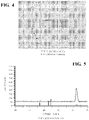
- Figure 4 is a micrograph of the CrWN coating of the present disclosure following a similar test regimen, and it will be seen that this coating does not manifest any cracking. Inclusion of a substitutional dopant, in this case tungsten at 5 atomic percent, greatly enhances the crack resistance of the alloy. This is believed to be due to a change in the crystallographic orientation of the material, as will be evident from Figures 5 and 6 .
- Figure 5 shows x-ray diffraction data for a CrN film showing a 220 crystallographic orientation.
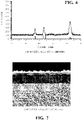
- Figure 6 shows corresponding x-ray diffraction data for the tungsten doped material of the present disclosure and, as will be seen, the material manifests 220, 111, and 200 orientations. This multiple directional, noncolumnar structure is believed to be responsible for the crack resistance of the doped material of the present disclosure.
- a composite structure was prepared utilizing the doped chromium nitride of the present disclosure in combination with a lubricious layer of titanium carbonitride. This produced a composite structure having an overall hardness of 3600-3800 Hv and a coefficient of friction of 0.1-0.15.
- Figure 7 is a cross-sectional micrograph of an article, such as a tool made of steel, having the composite coating of the present disclosure disposed thereupon.
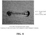
- Figure 8 is a micrograph of the surface of the coated article of Figure7 following 1500 cycles of testing in the apparatus of Figure 1 under a 400 N impact load and a 400 N sliding load. As will be seen, even under these extreme conditions, no wear through of the upper lubricious layer has been seen.
- the present disclosure provides a composite layer coating in which the component layers thereof interact synergistically to provide combined resistance to impact and sliding friction under very high pressure conditions which are encountered in the forming of AHSS alloy materials.
- use of the coatings of the present disclosure greatly prolongs service life of dies and other metal forming materials thereby minimizing equipment cost and downtime.
Landscapes
- Chemical & Material Sciences (AREA)
- Engineering & Computer Science (AREA)
- Mechanical Engineering (AREA)
- Materials Engineering (AREA)
- Chemical Kinetics & Catalysis (AREA)
- Metallurgy (AREA)
- Organic Chemistry (AREA)
- Inorganic Chemistry (AREA)
- General Chemical & Material Sciences (AREA)
- Ceramic Engineering (AREA)
- Physics & Mathematics (AREA)
- Plasma & Fusion (AREA)
- Physical Vapour Deposition (AREA)
- Mounting, Exchange, And Manufacturing Of Dies (AREA)
- Laminated Bodies (AREA)
- Other Surface Treatments For Metallic Materials (AREA)
Description
- This application claims priority benefit to
U.S. provisional patent application serial number 61/716965 filed October 22, 2012 - The present disclosure relates generally to tools and dies used in metal forming applications. More specifically, the disclosure relates to a fatigue-, wear-, and friction-resistant composite coating, and to metal forming members having that coating disposed on their surface.
- Metal forming members such as dies and the like are exposed to high cyclical pressure and high friction conditions. Recently the industry has turned to the use of advanced high strength steel alloys (AHSS) which exhibit tensile strengths far greater than those shown by previously employed steel alloys. Typical AHSS alloys manifest tensile strengths which exceed 700 MPa. In particular instances, alloys having tensile strengths in the range of 900-1200 MPa are employed in the fabrication of structural components for automobiles and the like. Owing to their high strength, AHSS steels are very difficult to form and dies used for their forming are exposed to high impact and high pressure conditions. In addition to the high impact and high pressure conditions, the surfaces of the dies experience very high frictional forces in use. These high pressure, high friction conditions can cause extreme wear to forming dies and the like, thereby greatly compromising their service life.
- In some instances, the prior art has sought to harden the surfaces of the dies by various treatment processes; however, these results have produced only limited success. In other approaches, dies have been coated with various high hardness, wear resistant coatings including titanium nitride, titanium carbonitride, chromium nitride, titanium aluminum nitride, and the like. In other approaches, thermal diffusion coatings of materials such as vanadium carbide and chemical vapor deposition (CVD) coatings such as titanium carbide have been utilized. While each of these surface enhancement techniques have demonstrated success in extending the service life of dies used to form conventional alloys having strength levels below 400 MPa, they all manifest poor performance in forming operations involving AHSS alloys.
- In some instances, thermal diffusion and CVD coatings have been found to extend the service life of dies used for forming AHSS alloys. However, both of these processes tend to produce changes in the dimensions of the dies resultant from changes in crystal structure during the deposition and heat treatment of commonly used tool steel die materials. The magnitude of these dimensional changes is very often outside the dimensional specifications defined by the users of the forming dies; hence, such processes are generally not acceptable. Further, thermal diffusion coatings have relatively high coefficients of friction and are incompatible with the high levels of frictional forces generated in the forming of high tensile strength AHSS materials.
- While plasma vapor deposition (PVD) coatings, unlike CVD coatings and thermal diffusion coatings, do not cause unacceptable dimensional changes to the forming dies, many of such coatings have other limitations which restrict their use in high tensile strength material forming applications. Because of their columnar structure, PVD coatings such as chromium nitride, titanium aluminum nitride, and the like are susceptible to cracking when subjected to high pressure/impact conditions such as those found in the forming of materials having tensile strengths greater than 400 MPa. Some increase in die performance has been achieved by case hardening the surfaces of the dies prior to coating with conventional PVD coatings since the increased surface hardness of the die prevents deformation and cracking of the coating. But, this approach produces only limited success and is useful only in those instances where the tensile strengths of the steel alloys being formed are below 800 MPa.
EP 1 245 699 A2 - As a consequence, there is a need for coatings and methods for improving the service life of metal forming members such as dies, used in connection with the shaping of AHSS alloy materials. Such coatings should be durable under very high pressure and high friction conditions encountered in the forming process and should not adversely affect the dimensional parameters of the die. In addition, processes for applying the coatings should be simple, economical, easy to implement, and recoatable. As will be explained in detail hereinbelow, the present disclosure provides a composite coating for metal forming members which achieves the foregoing goals.
- The present disclosure provides for a composite coating for a metal forming member. The coating includes a metal forming member and a first layer disposed on the metal forming member. The first layer includes chromium nitride doped with at least one dopant, wherein said dopant is selected from the group consisting of one or more of: W, V, Ti, Zr, Co, Mo, and Ta. A second layer is disposed atop the first layer, wherein said second layer comprises at least one material selected from the group of nitrides, carbonitrides, oxides, oxynitrides, carbon based coatings, molybdenum based solid film lubricant coatings, and combinations thereof. The second layer includes a lubricious material having optionally a coefficient of friction of less than or equal to 0.2 as measured against low alloy steel. The dopant is selected from the group consisting of one or more of: W, V, Ti, Zr, Co, Mo, and Ta. In an example, the dopant is W. The dopant can be present in a range of 1 to 10 atomic percent, such as a range of 3 to 7 atomic percent, and in particular instances said dopant is present in and amount of approximately 5 atomic percent. The thickness of the first layer can be in the range of 1 to 10 micrometers, such as a range of 4 to 6 micrometers. The hardness of the first layer can be in the range of 2 to 5 KHv, such as 3 to 4 KHv, and in particular instances 3.6 to 3.8 KHv.
- In a further example, the second layer has a coefficient of friction in the range of 0.1 to 0.15 as measured against low alloy steel. The thickness of the second layer can be in the range of 0.5 to 5 micrometers, and in particular instances 1.2 micrometers. The second layer includes at least one material selected from the group of nitrides, carbonitrides, oxides, oxynitrides, carbon based coatings, molybdenum based solid film lubricant coatings, and combinations thereof. In yet a further example, the second layer comprises TiCN.
- The present disclosure further provides for a metal forming member including the composite coating of any of those described herein. The metal forming member can include a die.
- The present disclosure further provides for a method of coating a metal forming member including applying the composite coating of any one of the previously described coatings thereto. At least one of the layers of the composite coating may be applied by a plasma vapor deposition process. In a further example, the present disclosure provides for a method of forming a body of an advanced high strength steel. The method including the use of the metal forming member as described herein. The advanced high strength steel can have a tensile strength of at least 700 MPa, such as a strength of at least 900 MPa, and in particular instances a strength of at least 1000 MPa.
- The following detailed description may best be understood by reference to the following drawings, in which:
-
Figure 1A illustrates an example test apparatus which was used for carrying out evaluations of impact and sliding wear of various coating materials in a rest position (rotated position shown in phantom dashed lines). -
Figure 1B illustrates the example test apparatus ofFigure 1A in a rotated position. -
Figure 2 illustrates a micrograph of an undoped CrN coating layer of the prior art following high pressure impact. -
Figure 3 illustrates a top view of the prior art CrN layer following cycling in the apparatus ofFigure 1 under conditions of a 200 N impact and 400 N sliding friction. -
Figure 4 illustrates a micrograph of a CrWN coating according to the present disclosure following a similar test regimen asFigure 3 . -
Figure 5 illustrates x-ray diffraction data for a prior art CrN film showing a 220 crystallographic orientation. -
Figure 6 illustrates x-ray diffraction data for a tungsten doped material according to the present disclosure. -
Figure 7 illustrates a cross-sectional micrograph of an article having a composite coating of the present disclosure disposed thereupon. -
Figure 8 illustrates a micrograph of a surface of the coated article ofFigure7 following 1500 cycles of testing in the apparatus ofFigure 1 under a 400 N impact load and a 400 N sliding load. - The present disclosure is directed to a composite coating for a metal forming member such as a die or the like. The coating is disposed on at least a forming surface of a metalworking member and comprises a first layer of a doped chromium nitride ceramic. Chromium nitride is a high hardness material, but the columnar nature of the basic material can cause it to manifest cracks under high pressure conditions. In accord with the present disclosure, it was found that inclusion of relatively small amounts of a dopant material, for example in a range of 1-10 atomic percent, greatly limits the formation and/or propagation of cracks through the material. While not wishing to be bound by speculation, it is presumed that the dopant material substitutes in the crystalline matrix of the chromium nitride so as to prevent the propagation of cracks therethrough. The dopant is selected from the group consisting of one or more of: W, V, Ti, Zr, Co, Mo, and Ta . In some instances, W is employed as a dopant. As noted above, dopant levels of 1-10 atomic percent, which are consistent with substitutional doping, can be employed and, in particular instances, dopant levels fall in the range of 3-7 atomic percent, with 5 atomic percent being one particular dopant level.
- In an example, the first layer of material generally has a thickness in the range of 1-10 micrometers, and in specific instances approximately 4-6 micrometers. Hardness of the first layer is typically in the range of 3000-4000 Hv, and one particular material utilized in the present disclosure comprises CrN doped with approximately 5 atomic percent W and manifests a hardness in the range of 3200-3800 Hv.
- Disposed atop the first layer is a second layer which is comprised of a lubricious material. The second layer comprises at least one material selected from the group of nitrides, carbonitrides, oxides, oxynitrides, carbon based coatings, molybdenum based solid film lubricant coatings, and combinations thereof. In accord with the present disclosure, it was found that this second layer should have a low coefficient of friction, typically below 0.2 against steel; and in particular instances, the second layer has a coefficient of friction in the range of 0.1-0.15. The layer of lubricious material will typically have a thickness less than that of the layer of doped chromium nitride and will generally have a thickness in the range of 0.5-5 micrometers and, in particular instances, a thickness in the range of 1-3 micrometers. A number of materials may be employed for forming the lubricious layer, and these materials comprise nitrides, carbonitrides, oxides, oxynitrides, carbon based coatings, or molybdenum based solid film lubricant coatings and the like. In an example, the specific material utilized in the present disclosure comprises TiCN, and other such materials will be readily apparent to those of skill in the art.
- It was determined that the combination of the substitutionally doped chromium nitride together with a low coefficient of friction lubricious layer provides a wear-resistant coating capable of providing a relatively long service life under high impact and high friction forming conditions encountered in the use of AHSS alloy materials.
- Coatings of the present disclosure may advantageously be prepared by a plasma vapor deposition (PVD) process wherein at least one, and preferably both, of the layers are formed. Such processes are cost effective and may be readily controlled to produce uniform, precise layer thicknesses on complex surfaces of metal forming dies and the like. Such PVD processes are well known in the art. In some instances the methods of the present disclosure may be combined with pre- and post-treatment processes which maximize performance of the die and coating. For example, the die material itself may be polished and/or case hardened by techniques such as nitriding, carburizing, and ferritic carburizing as is known in the art. In instances where very high tensile strength alloys are being formed, such hardening processes have been found to be advantageous. Likewise, hardening techniques are advantageously employed when the die material itself is of relatively low strength. Also, it may be advantageous in some instances to polish the coated die surface so as to further increase its galling resistance.
- In the present disclosure, the combination of impact resistance, primarily from the doped chromium nitride, and a low coefficient of friction, primarily from the second layer, produces superior fatigue resistance as compared to that which would be achieved by each layer individually. As will be detailed hereinbelow, the combination of layers interacts synergistically to greatly enhance the service life of coated dies under high pressure, high friction conditions.
- The principles of the present disclosure are illustrated by a particular series of experiments and examples directed to a composite coating comprising a first, high hardness, layer of chromium nitride doped with approximately 5 atomic percent of tungsten and having a thickness in the range of 4-6 microns and a second, lubricious, layer comprised of titanium carbonitride having a thickness of approximately 1-2 microns. The overall hardness of this coating is in the range of 3600-3800 Hv and its coefficient of friction is in the range of 0.1-0.15.
- Referring now to
Figures 1A-1B , there is shown a test apparatus which was used for carrying out evaluations of impact and sliding wear of various coating materials. In the apparatus, asample 3 is impacted by ahardened carbide ball 2 driven by anair cylinder 1. The sample can be a steel tool that includes a surface coating according to the present disclosure. Thesample 3 is mounted on arotatable rocker arm 5, which supported on arigid frame 4 through aroller bearing 7. Therocker arm 5 is biased by areturn spring assembly 6 which controls the amount of force delivered to the coating onsample 3. Following initial impact of the sample by the ball, the rocker arm pivots, allowing the ball to slide along the surface coating of the specimen. Therocker arm 5 is shown at rest inFigure 1A and rotated inFigure 1B with thehardened ball 2 slid to a different position against thesample 3 coated surface. Dashed lines represent the movement of the objects in phantom as therocker arm 5 rotates during impact inFigure 1A . - As shown in
Figures 1A-1B , a typical wear scar can represent a head to tail appearance. In these examples, testing was performed at room temperature. In an a particular example, impact load was held at 80N with a sliding load at 200N. In another example, impact load is applied between about 200-400N with a 400N sliding load. -
Figure 2 is a micrograph of a typical undoped CrN coating layer following high pressure impact. As will be seen, following a series of approximately 1500 cycles under an impact load of 80 N and a sliding load of 200 N, a number of cracks have formed in and propagated through the CrN layer.Figure 3 is a top view of the CrN layer following cycling in the apparatus ofFigure 1 under conditions of a 200 N impact and 400 N sliding friction. As will be seen, cracks begin to show in the coating. -
Figure 4 is a micrograph of the CrWN coating of the present disclosure following a similar test regimen, and it will be seen that this coating does not manifest any cracking. Inclusion of a substitutional dopant, in this case tungsten at 5 atomic percent, greatly enhances the crack resistance of the alloy. This is believed to be due to a change in the crystallographic orientation of the material, as will be evident fromFigures 5 and6 .Figure 5 shows x-ray diffraction data for a CrN film showing a 220 crystallographic orientation.Figure 6 shows corresponding x-ray diffraction data for the tungsten doped material of the present disclosure and, as will be seen, the material manifests 220, 111, and 200 orientations. This multiple directional, noncolumnar structure is believed to be responsible for the crack resistance of the doped material of the present disclosure. - In an example, a composite structure was prepared utilizing the doped chromium nitride of the present disclosure in combination with a lubricious layer of titanium carbonitride. This produced a composite structure having an overall hardness of 3600-3800 Hv and a coefficient of friction of 0.1-0.15.
Figure 7 is a cross-sectional micrograph of an article, such as a tool made of steel, having the composite coating of the present disclosure disposed thereupon.Figure 8 is a micrograph of the surface of the coated article ofFigure7 following 1500 cycles of testing in the apparatus ofFigure 1 under a 400 N impact load and a 400 N sliding load. As will be seen, even under these extreme conditions, no wear through of the upper lubricious layer has been seen. Some cracking is evident at the impact site, but this is related to overload and deformation of the base material which supports the coating. In the case where the base is case hardened, this cracking will not be seen. It is notable that there is no cracking seen in the remainder of the material. - As will be seen from the foregoing experimental series, the present disclosure provides a composite layer coating in which the component layers thereof interact synergistically to provide combined resistance to impact and sliding friction under very high pressure conditions which are encountered in the forming of AHSS alloy materials. As a result, use of the coatings of the present disclosure greatly prolongs service life of dies and other metal forming materials thereby minimizing equipment cost and downtime.
- While the present disclosure has been described with reference to some specific embodiments, it is to be understood that other modifications and variations may be readily implemented as long as they fall within the wording of the independent claims. For example, additional high hardness and/or lubricious layers may be incorporated in the structure of the composite coatings of the present invention.
Claims (11)
- A metal forming member coated with a composite coating comprising:a metal forming member,a first layer disposed on said metal forming member, said first layer including chromium nitride doped with at least one dopant; anda second layer disposed atop said first layer, said second layer including a lubricious material,wherein said dopant is selected from the group consisting of one or more of W, V, Ti, Zr, Co, Mo, and Ta, andwherein said second layer comprises at least one material selected from the group of nitrides, carbonitrides, oxides, oxynitrides, carbon based coatings, molybdenum based solid film lubricant coatings, and combinations thereof.
- The member of claim 1, wherein said dopant is W.
- The member of claim 1 or 2, wherein said dopant is present in a range of 1-10 atomic percent, such as a range of 3-7 atomic percent, and in particular instances said dopant is present in an amount of 5 atomic percent.
- The member of any one of claims 1-3, wherein the thickness of said first layer is in the range of 1-10 micrometers, such as a range of 4-6 micrometers.
- The member of any one of claims 1-4, wherein the thickness of said second layer is in the range of 0.5-5 micrometers, and in particular instances 1.2 micrometers.
- The member of any one of claims 1-5, wherein said second layer comprises TiCN
- The metal forming member of anyone of claims 1-6, the member being a die.
- A method of coating a metal forming member comprising:
providing the metal forming member, depositing the composite coating of any one of claims 1-6 on said metal forming member. - The method of claim 8, wherein at least one of said layers of said composite coating is applied by a plasma vapor deposition process.
- A method of forming a body of an advanced high strength steel, said method comprising the use of the metal forming member of claim 7.
- The method of claim 10, wherein said advanced high strength steel has a tensile strength of at least 700 MPa, such as a strength of at least 900 MPa, and in particular instances a strength of at least 1000 MPa.
Applications Claiming Priority (2)
| Application Number | Priority Date | Filing Date | Title |
|---|---|---|---|
| US201261716965P | 2012-10-22 | 2012-10-22 | |
| PCT/US2013/045373 WO2014065892A1 (en) | 2012-10-22 | 2013-06-12 | Fatigue- resistant coating for metal forming members |
Publications (3)
| Publication Number | Publication Date |
|---|---|
| EP2909360A1 EP2909360A1 (en) | 2015-08-26 |
| EP2909360A4 EP2909360A4 (en) | 2016-07-06 |
| EP2909360B1 true EP2909360B1 (en) | 2022-08-03 |
Family
ID=50545071
Family Applications (1)
| Application Number | Title | Priority Date | Filing Date |
|---|---|---|---|
| EP13849145.1A Active EP2909360B1 (en) | 2012-10-22 | 2013-06-12 | Fatigue- resistant coating for metal forming members |
Country Status (9)
| Country | Link |
|---|---|
| US (1) | US10550477B2 (en) |
| EP (1) | EP2909360B1 (en) |
| JP (1) | JP6232438B2 (en) |
| KR (1) | KR101759923B1 (en) |
| CN (1) | CN104797739B (en) |
| CA (1) | CA2888240C (en) |
| IN (1) | IN2015DN03914A (en) |
| MX (1) | MX382282B (en) |
| WO (1) | WO2014065892A1 (en) |
Families Citing this family (4)
| Publication number | Priority date | Publication date | Assignee | Title |
|---|---|---|---|---|
| DK3262207T3 (en) | 2015-02-24 | 2019-03-25 | Oerlikon Surface Solutions Ag Pfaeffikon | HIGH-PERFORMANCE COATING FOR COLD METAL DESIGN OF HIGH STRENGTH STEEL |
| WO2023042267A1 (en) * | 2021-09-14 | 2023-03-23 | 株式会社 東芝 | Fastening member |
| CN114235616B (en) * | 2022-02-24 | 2022-05-17 | 艾瑞森表面技术(苏州)股份有限公司 | Coating testing equipment and coating testing method |
| CN115074677B (en) * | 2022-05-16 | 2023-06-23 | 清华大学 | CrWZrN multilayer gradient structure coating and its preparation method |
Family Cites Families (27)
| Publication number | Priority date | Publication date | Assignee | Title |
|---|---|---|---|---|
| US2353743A (en) * | 1941-08-26 | 1944-07-18 | Gen Electric | High-frequency electronic discharge device |
| US4943486A (en) * | 1987-04-01 | 1990-07-24 | Seiko Epson Corporation | Coated article and method of production |
| US5476134A (en) * | 1993-12-21 | 1995-12-19 | Aluminum Company Of America | CRN coated die-casting tools for casting low aluminum iron alloys and method of making same |
| JP2000239829A (en) * | 1999-02-17 | 2000-09-05 | Sumitomo Metal Mining Co Ltd | Material with solid lubrication film |
| US6274257B1 (en) * | 1999-10-29 | 2001-08-14 | Ionbond Inc. | Forming members for shaping a reactive metal and methods for their fabrication |
| WO2001092602A1 (en) * | 2000-05-30 | 2001-12-06 | Nkk Corporation | Organic coating covered steel sheet |
| JP2002307128A (en) * | 2001-04-10 | 2002-10-22 | Hitachi Metals Ltd | Coating tool for warm and hot working having excellent seizure resistance and wear resistance |
| EP1245699B1 (en) * | 2001-03-30 | 2011-05-11 | Hitachi Metals, Ltd. | Coated tool for warm and/or hot working |
| JP4122387B2 (en) | 2002-03-15 | 2008-07-23 | 山口県 | Composite hard coating, method for producing the same, and film forming apparatus |
| CN100419117C (en) * | 2004-02-02 | 2008-09-17 | 株式会社神户制钢所 | Hard laminated film, method for producing same, and film forming apparatus |
| US8146889B2 (en) * | 2004-08-27 | 2012-04-03 | Vetco Gray Inc. | Low friction coatings for dynamically engaging load bearing surfaces |
| WO2006084404A1 (en) * | 2005-02-10 | 2006-08-17 | Oerlikon Trading Ag, Trübbach | High wear resistant triplex coating for cutting tools |
| CN100371496C (en) * | 2005-07-07 | 2008-02-27 | 浙江大学 | A kind of self-lubricating multi-layer composite coating and preparation method thereof |
| US8129041B2 (en) * | 2006-10-26 | 2012-03-06 | General Electric Company | Article having a protective coating and methods |
| DE102007027245B4 (en) * | 2007-06-13 | 2018-08-30 | Federal-Mogul Burscheid Gmbh | piston ring |
| US20090074522A1 (en) * | 2007-09-17 | 2009-03-19 | Northwestern University | Reduced-friction coatings |
| JP2009167488A (en) * | 2008-01-18 | 2009-07-30 | Nippon Coating Center Kk | Composite wear-resistant hard coating with solid lubricity and non-affinity |
| FR2934608B1 (en) * | 2008-08-01 | 2010-09-17 | Commissariat Energie Atomique | SUPERFINISHING THIN FILM COATING, PROCESS FOR OBTAINING SAME, AND DEVICE COMPRISING SUCH A COATING. |
| CN101643889B (en) * | 2008-08-07 | 2012-10-10 | 三菱重工业株式会社 | Part for rotary machine and its method of manufacture |
| DE102008042747A1 (en) * | 2008-10-10 | 2010-04-15 | Federal-Mogul Burscheid Gmbh | Sliding element in an internal combustion engine, in particular piston ring |
| CN101608299B (en) * | 2009-07-13 | 2010-12-29 | 四川大学 | High hardness and low friction Cr/CrCN gradient coating technology applicable to surface of profiled reed |
| IT1397559B1 (en) * | 2010-01-15 | 2013-01-16 | Scattolon | PERFECTED MOLD FOR BENDING THE SHEET |
| CN102233698B (en) * | 2010-04-23 | 2014-12-10 | 鸿富锦精密工业(深圳)有限公司 | Surface strengthening matrix and preparation method thereof |
| KR101253838B1 (en) * | 2010-12-27 | 2013-04-12 | 주식회사 포스코 | Method for Manufacturing a Multi Physical Property Part |
| DE102011010401A1 (en) * | 2011-02-04 | 2012-08-23 | Oerlikon Trading Ag, Trübbach | Cr-Si-N coated tools for forming or punching hot metal plates |
| KR20130060544A (en) * | 2011-11-30 | 2013-06-10 | 현대자동차주식회사 | Method and apparatus for forming coating layer with nano multi-layer |
| CN102424972A (en) * | 2011-12-02 | 2012-04-25 | 东宇东庵(天津)热处理系统有限公司 | Method for manufacturing composite coating on metal surface |
-
2013
- 2013-06-12 EP EP13849145.1A patent/EP2909360B1/en active Active
- 2013-06-12 JP JP2015537690A patent/JP6232438B2/en active Active
- 2013-06-12 WO PCT/US2013/045373 patent/WO2014065892A1/en not_active Ceased
- 2013-06-12 US US14/434,232 patent/US10550477B2/en active Active
- 2013-06-12 CA CA2888240A patent/CA2888240C/en active Active
- 2013-06-12 CN CN201380055277.8A patent/CN104797739B/en active Active
- 2013-06-12 IN IN3914DEN2015 patent/IN2015DN03914A/en unknown
- 2013-06-12 KR KR1020157012897A patent/KR101759923B1/en active Active
- 2013-06-12 MX MX2015005048A patent/MX382282B/en unknown
Non-Patent Citations (3)
| Title |
|---|
| FRANKLIN ET AL: "A comparison of the tribological behaviour of several wear-resistant coatings", SURFACE AND COATINGS TECHNOLOGY, ELSEVIER BV, AMSTERDAM, NL, vol. 54-55, 1 January 1992 (1992-01-01), pages 459 - 465, XP022428403, ISSN: 0257-8972, DOI: 10.1016/S0257-8972(07)80066-1 * |
| KONIG ET AL: "Performance and wear of carbide coated by physical vapour deposition in interrupted cutting", SURFACE AND COATINGS TECHNOLOGY, ELSEVIER BV, AMSTERDAM, NL, vol. 54-55, 1 January 1992 (1992-01-01), pages 453 - 458, XP022428402, ISSN: 0257-8972, DOI: 10.1016/S0257-8972(07)80065-X * |
| NAIR R P ET AL: "The use of the pin-on-disk tribology test method to study three unique industrial applications", WEAR, ELSEVIER SEQUOIA, LAUSANNE, CH, vol. 267, no. 5-8, 15 June 2009 (2009-06-15), pages 823 - 827, XP026138316, ISSN: 0043-1648, [retrieved on 20090526], DOI: 10.1016/J.WEAR.2009.02.026 * |
Also Published As
| Publication number | Publication date |
|---|---|
| US20150275370A1 (en) | 2015-10-01 |
| CN104797739B (en) | 2017-05-17 |
| KR101759923B1 (en) | 2017-07-20 |
| JP2016500759A (en) | 2016-01-14 |
| WO2014065892A1 (en) | 2014-05-01 |
| IN2015DN03914A (en) | 2015-10-02 |
| MX2015005048A (en) | 2015-12-01 |
| JP6232438B2 (en) | 2017-11-15 |
| KR20150077449A (en) | 2015-07-07 |
| US10550477B2 (en) | 2020-02-04 |
| CA2888240C (en) | 2020-09-08 |
| CN104797739A (en) | 2015-07-22 |
| MX382282B (en) | 2025-03-13 |
| CA2888240A1 (en) | 2014-05-01 |
| EP2909360A4 (en) | 2016-07-06 |
| EP2909360A1 (en) | 2015-08-26 |
Similar Documents
| Publication | Publication Date | Title |
|---|---|---|
| US7270719B2 (en) | Method for manufacturing surface hardened stainless steel with improved wear resistance and low static friction properties | |
| CN103459617B (en) | Method for producing a hardened, coated metal component | |
| EP1905863A2 (en) | Slide member | |
| CN103370438B (en) | There is thermometal plate forming or the press tool of Cr-Si-N coating | |
| US9968980B2 (en) | Coatings for forming tools | |
| KR102561370B1 (en) | High-performance coatings for cold forming of high-strength steel | |
| CA2888240C (en) | Fatigue-resistant coating for metal forming members | |
| JP4656473B2 (en) | Coated tool for hot working with excellent lubricant adhesion and wear resistance | |
| JP2021006660A (en) | Steel parts and their manufacturing methods | |
| Pereira et al. | Characterization of layers produced by boriding and boriding-PVD on AISI D2 tool steel | |
| JP7635713B2 (en) | Coated tool for hot stamping of coated or uncoated metal sheets and method for producing same - Patents.com | |
| JP2002307128A (en) | Coating tool for warm and hot working having excellent seizure resistance and wear resistance | |
| JP4771223B2 (en) | Durable hard material coated mold for plastic working | |
| JP2009293110A (en) | Method for manufacturing coated member and coated member | |
| JP2008150650A (en) | Steel-based composite surface treatment product and manufacturing method thereof | |
| Castillejo-Nieto et al. | Wear resistance of vanadium-niobium carbide layers grown via TRD | |
| JP2024009364A (en) | Method for manufacturing a target for forming a hard film and target for forming a hard film | |
| Goršćak et al. | Comparison of mechanical properties of various PVD hard coatings for forming tools | |
| Escher et al. | New trends in thin coatings for sheet metal forming tools | |
| JP2022548893A (en) | Substrate with molybdenum nitride coating system and coating method for producing coating system | |
| JP4547656B2 (en) | Coated tool for hot working with excellent lubricant adhesion and wear resistance | |
| KR100326772B1 (en) | Deposition Process of TiN on High Speed Steels | |
| Rolinski et al. | Plasma nitriding automotive stamping dies | |
| EP2876184B1 (en) | Use of a coated hot forming tool with a hard coating comprising a-C:H:W hard layer system for enhancing performance | |
| Ramadan et al. | Mathematical Modelingof Mechanical Properties of PVD Coated Steel Blanking Punch |
Legal Events
| Date | Code | Title | Description |
|---|---|---|---|
| PUAI | Public reference made under article 153(3) epc to a published international application that has entered the european phase |
Free format text: ORIGINAL CODE: 0009012 |
|
| 17P | Request for examination filed |
Effective date: 20150522 |
|
| AK | Designated contracting states |
Kind code of ref document: A1 Designated state(s): AL AT BE BG CH CY CZ DE DK EE ES FI FR GB GR HR HU IE IS IT LI LT LU LV MC MK MT NL NO PL PT RO RS SE SI SK SM TR |
|
| AX | Request for extension of the european patent |
Extension state: BA ME |
|
| DAX | Request for extension of the european patent (deleted) | ||
| REG | Reference to a national code |
Ref country code: DE Ref legal event code: R079 Ref document number: 602013082246 Country of ref document: DE Free format text: PREVIOUS MAIN CLASS: C23C0030000000 Ipc: C23C0028040000 |
|
| RA4 | Supplementary search report drawn up and despatched (corrected) |
Effective date: 20160606 |
|
| RIC1 | Information provided on ipc code assigned before grant |
Ipc: C23C 28/04 20060101AFI20160531BHEP Ipc: C23C 14/06 20060101ALI20160531BHEP Ipc: C23C 14/58 20060101ALI20160531BHEP |
|
| STAA | Information on the status of an ep patent application or granted ep patent |
Free format text: STATUS: EXAMINATION IS IN PROGRESS |
|
| 17Q | First examination report despatched |
Effective date: 20180918 |
|
| RAP1 | Party data changed (applicant data changed or rights of an application transferred) |
Owner name: IHI IONBOND AG |
|
| GRAP | Despatch of communication of intention to grant a patent |
Free format text: ORIGINAL CODE: EPIDOSNIGR1 |
|
| STAA | Information on the status of an ep patent application or granted ep patent |
Free format text: STATUS: GRANT OF PATENT IS INTENDED |
|
| INTG | Intention to grant announced |
Effective date: 20220107 |
|
| GRAS | Grant fee paid |
Free format text: ORIGINAL CODE: EPIDOSNIGR3 |
|
| GRAA | (expected) grant |
Free format text: ORIGINAL CODE: 0009210 |
|
| STAA | Information on the status of an ep patent application or granted ep patent |
Free format text: STATUS: THE PATENT HAS BEEN GRANTED |
|
| AK | Designated contracting states |
Kind code of ref document: B1 Designated state(s): AL AT BE BG CH CY CZ DE DK EE ES FI FR GB GR HR HU IE IS IT LI LT LU LV MC MK MT NL NO PL PT RO RS SE SI SK SM TR |
|
| REG | Reference to a national code |
Ref country code: AT Ref legal event code: REF Ref document number: 1508817 Country of ref document: AT Kind code of ref document: T Effective date: 20220815 Ref country code: CH Ref legal event code: EP |
|
| REG | Reference to a national code |
Ref country code: DE Ref legal event code: R096 Ref document number: 602013082246 Country of ref document: DE |
|
| REG | Reference to a national code |
Ref country code: IE Ref legal event code: FG4D |
|
| REG | Reference to a national code |
Ref country code: SE Ref legal event code: TRGR |
|
| REG | Reference to a national code |
Ref country code: LT Ref legal event code: MG9D |
|
| REG | Reference to a national code |
Ref country code: NL Ref legal event code: MP Effective date: 20220803 |
|
| PG25 | Lapsed in a contracting state [announced via postgrant information from national office to epo] |
Ref country code: RS Free format text: LAPSE BECAUSE OF FAILURE TO SUBMIT A TRANSLATION OF THE DESCRIPTION OR TO PAY THE FEE WITHIN THE PRESCRIBED TIME-LIMIT Effective date: 20220803 Ref country code: PT Free format text: LAPSE BECAUSE OF FAILURE TO SUBMIT A TRANSLATION OF THE DESCRIPTION OR TO PAY THE FEE WITHIN THE PRESCRIBED TIME-LIMIT Effective date: 20221205 Ref country code: NO Free format text: LAPSE BECAUSE OF FAILURE TO SUBMIT A TRANSLATION OF THE DESCRIPTION OR TO PAY THE FEE WITHIN THE PRESCRIBED TIME-LIMIT Effective date: 20221103 Ref country code: NL Free format text: LAPSE BECAUSE OF FAILURE TO SUBMIT A TRANSLATION OF THE DESCRIPTION OR TO PAY THE FEE WITHIN THE PRESCRIBED TIME-LIMIT Effective date: 20220803 Ref country code: LV Free format text: LAPSE BECAUSE OF FAILURE TO SUBMIT A TRANSLATION OF THE DESCRIPTION OR TO PAY THE FEE WITHIN THE PRESCRIBED TIME-LIMIT Effective date: 20220803 Ref country code: LT Free format text: LAPSE BECAUSE OF FAILURE TO SUBMIT A TRANSLATION OF THE DESCRIPTION OR TO PAY THE FEE WITHIN THE PRESCRIBED TIME-LIMIT Effective date: 20220803 Ref country code: FI Free format text: LAPSE BECAUSE OF FAILURE TO SUBMIT A TRANSLATION OF THE DESCRIPTION OR TO PAY THE FEE WITHIN THE PRESCRIBED TIME-LIMIT Effective date: 20220803 Ref country code: ES Free format text: LAPSE BECAUSE OF FAILURE TO SUBMIT A TRANSLATION OF THE DESCRIPTION OR TO PAY THE FEE WITHIN THE PRESCRIBED TIME-LIMIT Effective date: 20220803 |
|
| REG | Reference to a national code |
Ref country code: AT Ref legal event code: MK05 Ref document number: 1508817 Country of ref document: AT Kind code of ref document: T Effective date: 20220803 |
|
| PG25 | Lapsed in a contracting state [announced via postgrant information from national office to epo] |
Ref country code: PL Free format text: LAPSE BECAUSE OF FAILURE TO SUBMIT A TRANSLATION OF THE DESCRIPTION OR TO PAY THE FEE WITHIN THE PRESCRIBED TIME-LIMIT Effective date: 20220803 Ref country code: IS Free format text: LAPSE BECAUSE OF FAILURE TO SUBMIT A TRANSLATION OF THE DESCRIPTION OR TO PAY THE FEE WITHIN THE PRESCRIBED TIME-LIMIT Effective date: 20221203 Ref country code: HR Free format text: LAPSE BECAUSE OF FAILURE TO SUBMIT A TRANSLATION OF THE DESCRIPTION OR TO PAY THE FEE WITHIN THE PRESCRIBED TIME-LIMIT Effective date: 20220803 Ref country code: GR Free format text: LAPSE BECAUSE OF FAILURE TO SUBMIT A TRANSLATION OF THE DESCRIPTION OR TO PAY THE FEE WITHIN THE PRESCRIBED TIME-LIMIT Effective date: 20221104 |
|
| PG25 | Lapsed in a contracting state [announced via postgrant information from national office to epo] |
Ref country code: SM Free format text: LAPSE BECAUSE OF FAILURE TO SUBMIT A TRANSLATION OF THE DESCRIPTION OR TO PAY THE FEE WITHIN THE PRESCRIBED TIME-LIMIT Effective date: 20220803 Ref country code: RO Free format text: LAPSE BECAUSE OF FAILURE TO SUBMIT A TRANSLATION OF THE DESCRIPTION OR TO PAY THE FEE WITHIN THE PRESCRIBED TIME-LIMIT Effective date: 20220803 Ref country code: DK Free format text: LAPSE BECAUSE OF FAILURE TO SUBMIT A TRANSLATION OF THE DESCRIPTION OR TO PAY THE FEE WITHIN THE PRESCRIBED TIME-LIMIT Effective date: 20220803 Ref country code: CZ Free format text: LAPSE BECAUSE OF FAILURE TO SUBMIT A TRANSLATION OF THE DESCRIPTION OR TO PAY THE FEE WITHIN THE PRESCRIBED TIME-LIMIT Effective date: 20220803 Ref country code: AT Free format text: LAPSE BECAUSE OF FAILURE TO SUBMIT A TRANSLATION OF THE DESCRIPTION OR TO PAY THE FEE WITHIN THE PRESCRIBED TIME-LIMIT Effective date: 20220803 |
|
| REG | Reference to a national code |
Ref country code: DE Ref legal event code: R097 Ref document number: 602013082246 Country of ref document: DE |
|
| PG25 | Lapsed in a contracting state [announced via postgrant information from national office to epo] |
Ref country code: SK Free format text: LAPSE BECAUSE OF FAILURE TO SUBMIT A TRANSLATION OF THE DESCRIPTION OR TO PAY THE FEE WITHIN THE PRESCRIBED TIME-LIMIT Effective date: 20220803 Ref country code: EE Free format text: LAPSE BECAUSE OF FAILURE TO SUBMIT A TRANSLATION OF THE DESCRIPTION OR TO PAY THE FEE WITHIN THE PRESCRIBED TIME-LIMIT Effective date: 20220803 |
|
| PLBE | No opposition filed within time limit |
Free format text: ORIGINAL CODE: 0009261 |
|
| STAA | Information on the status of an ep patent application or granted ep patent |
Free format text: STATUS: NO OPPOSITION FILED WITHIN TIME LIMIT |
|
| PG25 | Lapsed in a contracting state [announced via postgrant information from national office to epo] |
Ref country code: AL Free format text: LAPSE BECAUSE OF FAILURE TO SUBMIT A TRANSLATION OF THE DESCRIPTION OR TO PAY THE FEE WITHIN THE PRESCRIBED TIME-LIMIT Effective date: 20220803 |
|
| 26N | No opposition filed |
Effective date: 20230504 |
|
| PG25 | Lapsed in a contracting state [announced via postgrant information from national office to epo] |
Ref country code: SI Free format text: LAPSE BECAUSE OF FAILURE TO SUBMIT A TRANSLATION OF THE DESCRIPTION OR TO PAY THE FEE WITHIN THE PRESCRIBED TIME-LIMIT Effective date: 20220803 |
|
| PG25 | Lapsed in a contracting state [announced via postgrant information from national office to epo] |
Ref country code: MC Free format text: LAPSE BECAUSE OF FAILURE TO SUBMIT A TRANSLATION OF THE DESCRIPTION OR TO PAY THE FEE WITHIN THE PRESCRIBED TIME-LIMIT Effective date: 20220803 |
|
| PG25 | Lapsed in a contracting state [announced via postgrant information from national office to epo] |
Ref country code: MC Free format text: LAPSE BECAUSE OF FAILURE TO SUBMIT A TRANSLATION OF THE DESCRIPTION OR TO PAY THE FEE WITHIN THE PRESCRIBED TIME-LIMIT Effective date: 20220803 |
|
| REG | Reference to a national code |
Ref country code: CH Ref legal event code: PL |
|
| REG | Reference to a national code |
Ref country code: BE Ref legal event code: MM Effective date: 20230630 |
|
| PG25 | Lapsed in a contracting state [announced via postgrant information from national office to epo] |
Ref country code: LU Free format text: LAPSE BECAUSE OF NON-PAYMENT OF DUE FEES Effective date: 20230612 |
|
| REG | Reference to a national code |
Ref country code: IE Ref legal event code: MM4A |
|
| PG25 | Lapsed in a contracting state [announced via postgrant information from national office to epo] |
Ref country code: LU Free format text: LAPSE BECAUSE OF NON-PAYMENT OF DUE FEES Effective date: 20230612 |
|
| PG25 | Lapsed in a contracting state [announced via postgrant information from national office to epo] |
Ref country code: IE Free format text: LAPSE BECAUSE OF NON-PAYMENT OF DUE FEES Effective date: 20230612 |
|
| PG25 | Lapsed in a contracting state [announced via postgrant information from national office to epo] |
Ref country code: IE Free format text: LAPSE BECAUSE OF NON-PAYMENT OF DUE FEES Effective date: 20230612 Ref country code: CH Free format text: LAPSE BECAUSE OF NON-PAYMENT OF DUE FEES Effective date: 20230630 |
|
| PG25 | Lapsed in a contracting state [announced via postgrant information from national office to epo] |
Ref country code: BE Free format text: LAPSE BECAUSE OF NON-PAYMENT OF DUE FEES Effective date: 20230630 |
|
| PG25 | Lapsed in a contracting state [announced via postgrant information from national office to epo] |
Ref country code: BG Free format text: LAPSE BECAUSE OF FAILURE TO SUBMIT A TRANSLATION OF THE DESCRIPTION OR TO PAY THE FEE WITHIN THE PRESCRIBED TIME-LIMIT Effective date: 20220803 |
|
| PG25 | Lapsed in a contracting state [announced via postgrant information from national office to epo] |
Ref country code: BG Free format text: LAPSE BECAUSE OF FAILURE TO SUBMIT A TRANSLATION OF THE DESCRIPTION OR TO PAY THE FEE WITHIN THE PRESCRIBED TIME-LIMIT Effective date: 20220803 |
|
| PGFP | Annual fee paid to national office [announced via postgrant information from national office to epo] |
Ref country code: DE Payment date: 20250520 Year of fee payment: 13 |
|
| PGFP | Annual fee paid to national office [announced via postgrant information from national office to epo] |
Ref country code: GB Payment date: 20250520 Year of fee payment: 13 |
|
| PGFP | Annual fee paid to national office [announced via postgrant information from national office to epo] |
Ref country code: IT Payment date: 20250520 Year of fee payment: 13 |
|
| PGFP | Annual fee paid to national office [announced via postgrant information from national office to epo] |
Ref country code: FR Payment date: 20250520 Year of fee payment: 13 |
|
| PG25 | Lapsed in a contracting state [announced via postgrant information from national office to epo] |
Ref country code: CY Free format text: LAPSE BECAUSE OF FAILURE TO SUBMIT A TRANSLATION OF THE DESCRIPTION OR TO PAY THE FEE WITHIN THE PRESCRIBED TIME-LIMIT; INVALID AB INITIO Effective date: 20130612 |
|
| PGFP | Annual fee paid to national office [announced via postgrant information from national office to epo] |
Ref country code: TR Payment date: 20250528 Year of fee payment: 13 |
|
| PGFP | Annual fee paid to national office [announced via postgrant information from national office to epo] |
Ref country code: SE Payment date: 20250520 Year of fee payment: 13 |
|
| PG25 | Lapsed in a contracting state [announced via postgrant information from national office to epo] |
Ref country code: HU Free format text: LAPSE BECAUSE OF FAILURE TO SUBMIT A TRANSLATION OF THE DESCRIPTION OR TO PAY THE FEE WITHIN THE PRESCRIBED TIME-LIMIT; INVALID AB INITIO Effective date: 20130612 |