EP2908621B1 - Animal watering device - Google Patents
Animal watering device Download PDFInfo
- Publication number
- EP2908621B1 EP2908621B1 EP13784028.6A EP13784028A EP2908621B1 EP 2908621 B1 EP2908621 B1 EP 2908621B1 EP 13784028 A EP13784028 A EP 13784028A EP 2908621 B1 EP2908621 B1 EP 2908621B1
- Authority
- EP
- European Patent Office
- Prior art keywords
- water
- trough
- water level
- watering device
- animal watering
- Prior art date
- Legal status (The legal status is an assumption and is not a legal conclusion. Google has not performed a legal analysis and makes no representation as to the accuracy of the status listed.)
- Active
Links
Images


Classifications
-
- A—HUMAN NECESSITIES
- A01—AGRICULTURE; FORESTRY; ANIMAL HUSBANDRY; HUNTING; TRAPPING; FISHING
- A01K—ANIMAL HUSBANDRY; CARE OF BIRDS, FISHES, INSECTS; FISHING; REARING OR BREEDING ANIMALS, NOT OTHERWISE PROVIDED FOR; NEW BREEDS OF ANIMALS
- A01K7/00—Watering equipment for stock or game
- A01K7/02—Automatic devices ; Medication dispensers
-
- A—HUMAN NECESSITIES
- A01—AGRICULTURE; FORESTRY; ANIMAL HUSBANDRY; HUNTING; TRAPPING; FISHING
- A01K—ANIMAL HUSBANDRY; CARE OF BIRDS, FISHES, INSECTS; FISHING; REARING OR BREEDING ANIMALS, NOT OTHERWISE PROVIDED FOR; NEW BREEDS OF ANIMALS
- A01K39/00—Feeding or drinking appliances for poultry or other birds
- A01K39/02—Drinking appliances
-
- H—ELECTRICITY
- H01—ELECTRIC ELEMENTS
- H01M—PROCESSES OR MEANS, e.g. BATTERIES, FOR THE DIRECT CONVERSION OF CHEMICAL ENERGY INTO ELECTRICAL ENERGY
- H01M10/00—Secondary cells; Manufacture thereof
- H01M10/42—Methods or arrangements for servicing or maintenance of secondary cells or secondary half-cells
- H01M10/46—Accumulators structurally combined with charging apparatus
-
- Y—GENERAL TAGGING OF NEW TECHNOLOGICAL DEVELOPMENTS; GENERAL TAGGING OF CROSS-SECTIONAL TECHNOLOGIES SPANNING OVER SEVERAL SECTIONS OF THE IPC; TECHNICAL SUBJECTS COVERED BY FORMER USPC CROSS-REFERENCE ART COLLECTIONS [XRACs] AND DIGESTS
- Y02—TECHNOLOGIES OR APPLICATIONS FOR MITIGATION OR ADAPTATION AGAINST CLIMATE CHANGE
- Y02E—REDUCTION OF GREENHOUSE GAS [GHG] EMISSIONS, RELATED TO ENERGY GENERATION, TRANSMISSION OR DISTRIBUTION
- Y02E60/00—Enabling technologies; Technologies with a potential or indirect contribution to GHG emissions mitigation
- Y02E60/10—Energy storage using batteries
Definitions
- the present invention relates to animal watering devices comprising a trough for holding water.
- Animal watering devices are used for watering animals. Devices of various sizes are known. For animal watering devices in sizes suitable for e.g. livestock, horses, pigs, and sheep, i.e. animal watering devices not particularly directed to pets, it is desirable that the watering devices are automatically refilled. Other functions such as automatic draining and automatic cleaning of the animal watering device may also be provided.
- US 3921587 discloses a self filling and self cleaning water fountain for bovine animals. Water is dispensed into a water tank of the fountain adjacent an upper edge of interior sides to wash the sides during each water fill operation. The washing water urges any sediment or debris adjacent the sides into the body of water, wherein it will settle on the bottom of the tank. The surface of the bottom undulates so as to urge the settled sediment and debris to accumulate in the troughs of the bottom surface, formed by the undulations. Each trough is drained via a separate drain through which the accumulated settled sediment and debris is exhausted.
- US 5813363 discloses an automatic dispenser for providing animals with cool fresh liquid (e.g., water).
- the feeder has self-cleaning and self-refilling features that provide periodic replacement of hot, stale or dirty fluid with cool fresh refills.
- Solenoid valves are controlled by one or more liquid sensors, a time delay relay, timer and optional thermostat to provide flexibility and customizing of drain/refill cycles as desired in order to reflect varying ambient conditions in which the equipment is operated.
- US 2008/257274 discloses a self-cleaning, water-saving automated animal watering device which includes a watering tank moveable between a lower, water-full condition and an upper, water-low condition. One end of the tank is pivotally supported by a pivot shaft, while the other end of the tank is biased upwardly via a lower lift spring.
- the device also has a water fill assembly operably coupled with tank to selectively fill the tank when needed, and a drain valve assembly also coupled with tank in order to completely drain the tank on a periodic basis.
- a control assembly Is coupled with at least the tank and drain valve assembly, and is operable to actuate the drain valve assembly after a predetermined number of movements of the tank between the elevated and lowered positions thereof.
- CN 201523595 U discloses an automatic portable watering trough, which comprises a power generating device.
- the power generating device provides energy to a pump for pumping water into a trough of the automatic portable watering trough.
- the power generating device supplies electricity for daily life of herdsmen. It appears from drawings in the document CN 201523595 U that the power generating device may comprise a solar panel and/or a wind-powered generator.
- An object of the invention is to provide an animal watering device comprising a water level control system, which animal watering device is usable in a location without an electric power connection.
- an animal watering device comprising a trough for holding water, a water conduit system in fluid communication with the trough and arranged to be connected to a water supply, an electric power consuming water level control system comprising a controller and at least one water level sensor arranged to sense a water level in the trough.
- the animal watering device further comprises an electric power unit.
- the electric power unit comprises an electric generator and an electrically chargeable unit.
- the water level control system is connected to the electrically chargeable unit.
- the electric generator is connected to the water conduit system.
- the electric generator is arranged to be driven by water from the water supply and to charge the electrically chargeable unit.
- the electric power unit comprises an electric generator arranged to be driven by water from the water supply and to charge the electrically chargeable unit, the above mentioned object is achieved.
- a water level in the trough may be controlled utilizing the electric power provided by the electric power unit.
- the water level sensor may e.g. be used for sensing a water level in the trough, to be used in connection with filling and/or draining the trough.
- an animal watering device may be self-supplying with electric power from an electric generator driven by water from a water supply connected to the animal watering device. It has been realized that the electric energy generated in this way is sufficient to power an electrically powered water level control system.
- the electric power unit and in particular the electric generator thereof simply relies on the water pressure of the incoming water from the water supply.
- the water supply may be provided e.g.1 by water mains, a built water reservoir, or a natural water reservoir such as a lake or a river.
- the water mains, ora height difference between the animal watering device and a water reservoir provides the water pressure required to drive the electric generator.
- a main criterion for the water supply is that the water supplied is suitable for animals to drink.
- the animal watering device may be of a size suitable for one animal only, or a number of animals simultaneously, drinking from its trough.
- the trough is a container which allows animals to drink therefrom.
- the animal watering device may comprise a support for the trough.
- the animal watering device may be placed indoors e.g. in an animal shed, or outdoors e.g. in a pasture.
- the animal watering device has to be connected to a water supply but other than that the animal watering device may be a stand-alone device.
- the animal watering device may be a built-in device of a construction such as a wall, a manger, or other feeding construction.
- the water level control system may comprise a timer.
- the water level in the trough may be controlled not only based on the water level but also, or alternatively, based on time.
- the timer may be implemented as a function in the controller.
- the at least one water level sensor may comprise a low level sensor arranged to sense a low water level in the trough. This enables drainage of the trough only when the water level in the trough is low.
- the at least one water level sensor may comprise a top level sensor arranged to sense a top water level in the trough. This enables filling of the trough to a predefined top water level.
- the at least one water level sensor may comprise a middle level sensor arranged to sense a middle water level in the trough. In this manner the water level in the trough may be more precisely controlled.
- the animal watering device may comprise a water outlet arranged at a bottom portion of the trough, and an outlet valve arrangement associated with the water outlet. In this manner the water level in the trough may be controlled.
- the trough may be drained via the water outlet, which may be opened and closed by means of the outlet valve arrangement.
- the water level control system may be arranged to open the water outlet when a first time interval has expired and a water level in the trough is at or below the low level sensor. In this manner it may be ensured that the trough is drained only when the water level in the trough is low.
- the water outlet may be opened by the outlet valve arrangement.
- the controller of the water level control system may be set to actuate the outlet valve arrangement to open the water outlet only when a first time interval has expired and a water level in the trough is low. If the first time interval has expired and the water level in the trough is above the low level sensor, the trough is not drained and the animals may continue to drink water from the trough until the water level is at or below the low level sensor. Only then the trough is drained.
- the water level control system may be arranged to open the water outlet when a second time interval has expired.
- the water level control system may be arranged to maintain the water outlet open during a third time interval. In this manner it may be ensured that the trough is completely drained.
- the water conduit system may be connected to an inlet nozzle arrangement. In this manner water may be directed into the trough via the inlet nozzle arrangement, the inlet arrangement leading into the trough.
- the inlet nozzle arrangement may comprise a first nozzle.
- the inlet nozzle arrangement may further comprise one or more second nozzles.
- the water level control system may be arranged to open the inlet nozzle arrangement during at least a part of the third time interval. In this manner the trough may be rinsed with clean water during draining of the trough.
- the water level control system may be arranged to open the inlet nozzle arrangement when a water level in the trough is at or below the low level sensor. In this manner the trough may be replenished with water when there is a low water level in the trough.
- the water level control system may be arranged to close the inlet nozzle arrangement when a water level in the trough is at or above the top level sensor.
- the water level control system may be arranged to open the inlet nozzle arrangement when a water level in the trough is at or below the middle level sensor. In this manner the trough may be replenished with water when there is a water level in the trough indicated by the middle water level sensor. When the water level is at or below the middle level sensor, the trough may be replenished with water. If the middle level sensor is used in this manner, after expiry of the first time interval, the trough is not replenished with water when the water level in the trough is at or below the middle level sensor.
- the outlet valve arrangement may comprise a valve body and a hydraulic cylinder connected to the valve body.
- the hydraulic cylinder may be utilized for opening and closing the water outlet of the trough.
- the valve body may comprise a lid.
- the lid may be provided to close the water outlet and may be manoeuvred by the hydraulic cylinder. Since a lid provides a distinct opening and closing of the water outlet, it may be ensured that the outlet valve arrangement is not blocked or hampered in its function by debris from the trough being caught in the outlet valve arrangement.
- the water conduit system may be connected to the hydraulic cylinder.
- the outlet valve arrangement may be actuated by water pressure.
- the controller may direct water to different chambers of the hydraulic cylinder, e.g. by means of one or more valves in the water conduit system.
- the electrically chargeable unit may be a rechargeable battery.
- the electrically chargeable unit may be e.g. a capacitor.
- the trough may comprise a bottom portion having a longitudinal direction and the bottom portion may be provided with a rib protruding from the bottom portion.
- the rib may be provided in a middle portion of the bottom portion and may extend substantially in the longitudinal direction. In this manner any debris in the water may deposit on both sides of the rib, which may facilitate draining the debris from the trough.
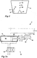
- Fig. 1 illustrates schematically a side view cross-section through an animal watering device 2 according to embodiments.
- the animal watering device 2 comprises a trough 4 for holding water as indicated by a water level 5.
- the animal watering device 2 also comprises a water conduit system 6 in fluid communication with the trough 4 and arranged to be connected to a water supply 8.
- the water pressure in the water conduit system 6 emanating from the water supply 8 may be about 1 bar, which pressure may be suitable e.g. for opening valves, setting hydraulic cylinders and filling or replenishing the trough 4.
- the water conduit system 6 is connected to an inlet nozzle arrangement 10.
- the inlet nozzle arrangement 10 may comprise one or more nozzles.
- the inlet nozzle arrangement 10 comprises a first nozzle 12 and a second nozzle 14.
- the inlet nozzle arrangement 10 is provided at the trough 4 such that the nozzle/s is/are directed into the trough 4 for admitting water through the nozzle/s into the trough 4.
- the animal watering device 2 further comprises a water outlet 16 arranged at a bottom portion 18 of the trough 4, and an outlet valve arrangement 20 associated with the water outlet 16.
- the outlet valve arrangement 20 comprises a hydraulic cylinder 21 and a valve body 22.
- the hydraulic cylinder 21 is connected to the valve body 22.
- the hydraulic cylinder 21 is arranged to actuate the valve body 22 in order to open and close the water outlet 16.
- the water conduit system 6 is connected to the hydraulic cylinder 21.
- a water level control system 24 is provided for controlling the animal watering device 2. For instance, filling and draining of the trough 4 may be controlled by the water level control system 24.
- the water level control system 24 comprises a controller 26, and a low level sensor 28 arranged to sense a low water level in the trough 4. That is, the low level sensor 28 is arranged inside the trough 4 and senses when the water level in the trough 4 is at or above the low level sensor 28.
- the controller 26 may for instance comprise a central processing unit running one or more control programs stored in a memory, discrete logic circuits, or a specifically designed ASIC (application-specific integrated circuit).
- the low level sensor 28 is connected to the controller 26.
- the controller 26 is further connected to one or more valves arranged in the water conduit system 6.
- the valves may be arranged to control water flow through the one or more nozzles of the inlet nozzle arrangement 10, control water directed to the chambers of the hydraulic cylinder 21, generally direct the flow of water in the water conduit system 6, etc.
- the controller 26 may control the valve/s based on signals from e.g. the low level sensor 28. For instance, the controller 26 may open a valve in the water conduit system 6 to replenish the trough 4 with water from the water source 8 through the water conduit system 6 and the nozzle inlet arrangement 10 when the water level 5 reaches the low level sensor 28.
- the water level control system 24 further comprises a timer 30.
- the timer 30 may be a separate unit or in some embodiments it may be implemented directly in the controller 26, e.g. as one or more tasks programmed in the controller 26.
- the timer 30 may be utilized for measuring one or more time intervals. Such time intervals may be used e.g. in connection with draining, filling, and rinsing the trough 4.
- the water level control system 24 may be arranged to open the water outlet 16 by actuating the outlet valve arrangement 20 when a first time interval has expired in the timer 30 and a water level in the trough is at or below the low level sensor 28.
- the water level control system 24 may be arranged to open the water outlet 16 by actuating the outlet valve arrangement 20 when a second time interval has expired.
- the second time interval always expires after the first time interval has expired. That is, if the second time interval is measured from the start of the first time interval, i.e. measuring of the first and second time intervals starts at the same time, the second time interval is longer that the first time interval. If the second time interval is measured from the end of the first time interval, the second time interval succeeds the first time interval. If measuring of the second time interval is started within the first time interval, the second time interval ends after the first time interval ends.
- the timer 30 may be reset e.g. in connection with draining the trough, e.g. when the water outlet 16 is opened or when the water outlet 16 is closed again after having been open, i.e. the timer 30 may be reset in connection with the expiry of the first time interval and the expiry of the second time interval.
- the water level control system 24 further comprises a top level sensor 32 and a middle level sensor 34.
- the top level sensor 32 is arranged to sense a top water level in the trough 4. That is, the top level sensor 32 is arranged inside the trough 4 and senses when the water level in the trough 4 is at or above the top level sensor 32.
- the middle level sensor 34 is arranged to sense a middle water level in the trough 4. That is, the middle level sensor 34 is arranged inside the trough 4 and senses when the water level in the trough 4 is at or above the middle sensor 34.
- the second and middle level sensors 32, 34 are connected to the controller 26.
- the animal watering device 2 comprises an electric generator 36 connected to an electrically chargeable unit 38.
- the electric generator 36 and electrically chargeable unit 38 form part of an electric power unit.
- the electric generator 36 is connected to the water conduit system 6, and is thus driven by water from the water supply flowing through the conduit system 6. Accordingly, the electric generator 36 comprises a rotor, which is driven by the water flowing in the water conduit system 6.
- the electric generator 36 is arranged to charge the electrically chargeable unit 38.
- the electrically chargeable unit 38 may comprise e.g. a chargeable battery.
- the electrically chargeable unit 38 is connected to the water level control system 24. Electric power from the electrically chargeable unit 38 may thus power the water level control system 24, in particular components of the water level control system 24, e.g. the controller 26, and sensors 28, 32,34.
- the trough 4 comprises the bottom portion 18.
- the trough 4 and the bottom portion 18 have a longitudinal direction 40.
- the longitudinal direction 40 extends along the longer of the two horizontal directions of the through 4.
- the water outlet 16 of the trough 4 is arranged at one end of the bottom portion 18, seen in the longitudinal direction 40.
- the bottom portion 18 is slanted towards the water outlet 16. Thus, it may be ensured that the trough 4 is completely drained when the water outlet 16 is opened.
- the bottom portion 18 is provided with a rib 42 protruding upwardly from the bottom portion 18.
- the rib 42 is provided in a middle portion of the bottom portion 18, seen both along and across the longitudinal direction 40.
- the rib 42 extends substantially in the longitudinal direction 40.
- the trough 4 may be 2 metres long in the longitudinal direction 40, 60 cm wide, i.e. across the longitudinal direction 40, and 30 cm deep at its deep end.
- the rib 42 may for instance have a length of 120 -180 cm, a width of 0,5 - 25 cm close to the bottom portion 18, and a height of 3 -10 cm.
- the rib 42 may have a wide base and a narrow top, e.g. as illustrated in Fig. 2 .
- Fig. 2 illustrates a cross-section through the animal watering device 2 illustrated in Fig. 1 , across the longitudinal direction 40.
- the nozzle arrangement 10 is arranged at one inner side of the trough 4. At least the first nozzle 12 of nozzle arrangement 10 is directed substantially in the longitudinal direction 40. Thus, water flowing into the trough 4 through the first nozzle 12 will be directed substantially in the longitudinal direction 40. Due to the arrangement of the rib 42 in the middle portion of the bottom portion 18 inflowing water from the first nozzle 12 will form a stream of water around the rib 42 to the water outlet 16.
- a water pressure of about 1,5 bar in the water conduit system 6 will ensure a strong stream around the rib 42 in a trough of the above exemplified size.
- the water outlet 16 may be opened during a third time interval and the water level control system 24 may be arranged to open the inlet nozzle arrangement 10 during at least a part of the third time interval.
- the trough 4 may be rinsed with clean water during draining of the trough 4.
- due to the rib 42 there is no stagnant water, and accordingly also no debris, at the middle portion of the bottom portion 18 as the water flows from the first nozzle 12 to the water outlet 16.
- Figs. 3a and 3b illustrate an outlet valve arrangement 20 of an animal watering device 2 according to embodiments.
- the animal watering device 2 may be an animal watering device 2 as illustrated and discussed in connection with Figs. 1 and 2 .
- the animal watering device 2 comprises a trough 4.
- the trough 4 is provided with a water outlet 16 arranged at a bottom portion of the trough 4.
- the outlet valve arrangement 20 is associated with the water outlet 16 and e.g. arranged for opening and closing the water outlet 16 and comprises a valve body 22 and a hydraulic cylinder 21 connected to the valve body 22. More specifically, a piston 43 of the hydraulic cylinder 21 is connected to the valve body 22.
- the valve body 22 comprises a lid 44 which is pivotably connected to the animal watering device 2.
- the lid 44 is arranged to close the water outlet 16. Accordingly, the lid 44 may be manoeuvred by the hydraulic cylinder 21. The lid 44 is arranged to abut against a rim 46 of the water outlet 16. The lid 44 may be provided with a rubber mat 48 which abuts against the rim 46 when the water outlet 16 is closed by the lid 44. The lid 44 provides a distinct opening and closing of the water outlet 16. Also, the arrangement of the lid 44 and the water outlet 16 being formed by an opening sufficiently large to permit debris in the form of straws and grass to flow out there through ensures that the outlet valve arrangement is not blocked or hampered in its function by such debris. Provided purely as an example, the water outlet 16 may have a through flow area of at least 200 mm 2 . and the water outlet 16 may suitably be free from obstacles to ensure draining of debris.
- the hydraulic cylinder 21 of the outlet valve arrangement 20 is connected to a water conduit system 6.
- the hydraulic cylinder 21 may thus be driven by the water pressure in the water conduit system 6.
- a control valve 50 of the outlet valve arrangement 20 for directing water from the water supply 8 to either one of two chambers 52, 54 of the hydraulic cylinder 21 is arranged in the water conduit system 6. Water from the respective chamber 52, 54 not being connected to the water supply 8 may be drained or directed into the trough 4.
- the two chambers 52, 54 are separated by the piston 43.
- the animal watering device 2 may comprise a water level control system as discussed in connection with Figs. 1 and 2 .
- the water level control system may be connected to the control valve 50 of the outlet valve arrangement 20.
- the water level control system thus may open and close the water outlet 16 by means of controlling the control valve 50 to direct water into one of the two chambers 52, 54 of the hydraulic cylinder 21.
- the outlet valve arrangement 20, or more specifically the control valve 50 may also be powered by electrically chargeable unit 38.
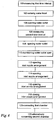
- Fig. 4 illustrates a method of controlling an animal watering device 2 as illustrated and discussed in connection with Figs. 1 , 2 , 3a and 3b .
- the method comprises:
- the method may comprise:
- the method may comprise:
- the method may comprise:
- the method may comprise:
- the method may comprise:
- the method may comprise:
- filling or replenishing the trough 4 may be based on a water level sensed by the low level sensor 28.
- the inlet nozzle arrangement 10 may be opened.
- the inlet nozzle arrangement 10 may be maintained open during a time interval of predetermined length.
- the inlet nozzle arrangement 10 may be closed when the water level in the trough 4 reaches the top level sensor 32, as mentioned above.
- the water level control system 24 comprises a middle level sensor 34 arranged to sense a middle water level in the trough 4
- the trough 4 may instead be filled or replenished by opening the inlet nozzle arrangement 10 when the water level is at or below the middle level sensor 34, as mentioned above.
- the inlet nozzle arrangement 10 may be maintained open during a time interval of predetermined length or the inlet nozzle arrangement 10 may be closed when the water level in the trough 4 reaches the top level sensor 32. If the water level control system 24 comprises a middle level sensor 34 used in this manner, after expiry of the first time interval, the sensor signal from the middle level sensor 34 is ignored by the water level control system 24. Thus, the trough 4 is not replenished with water when the water level in the trough 4 is below the middle level sensor 34. The opening 104 the water outlet 16 will take place once the water level in the trough 4 reaches the low level sensor 28, or after expiry of the second time interval.
- the method may comprise:
- the method may comprise:
- Example embodiments described above may be combined as understood by a person skilled in the art.
- filling and replenishing have the same practical meaning.
- the length of the first and second time intervals may be adapted to specific circumstances, which may e.g. take into account the volume of the trough, the number of animals being watered, the number of troughs available for watering the number of animals, environmental conditions such as presence of straws and dirt, the location of the trough, etc.
- the pressure in the conduit system 6 may be e.g. 1 bar or 1,5 bar.
- the pressure in the conduit system 6 emanating from the water supply 8 may alternatively be e.g. 2 - 3 bar or higher.
- the first nozzle 12 may be arranged below the one or more second nozzles 14 as illustrated in Figs 1 and 2 .
- the first nozzle may be arranged above the one or more second nozzles 14, or amidst one or more second nozzles 14, or laterally beside the one or more second nozzles 14.
Description
- The present invention relates to animal watering devices comprising a trough for holding water.
- Animal watering devices are used for watering animals. Devices of various sizes are known. For animal watering devices in sizes suitable for e.g. livestock, horses, pigs, and sheep, i.e. animal watering devices not particularly directed to pets, it is desirable that the watering devices are automatically refilled. Other functions such as automatic draining and automatic cleaning of the animal watering device may also be provided.
-
US 3921587 discloses a self filling and self cleaning water fountain for bovine animals. Water is dispensed into a water tank of the fountain adjacent an upper edge of interior sides to wash the sides during each water fill operation. The washing water urges any sediment or debris adjacent the sides into the body of water, wherein it will settle on the bottom of the tank. The surface of the bottom undulates so as to urge the settled sediment and debris to accumulate in the troughs of the bottom surface, formed by the undulations. Each trough is drained via a separate drain through which the accumulated settled sediment and debris is exhausted. -
US 5813363 discloses an automatic dispenser for providing animals with cool fresh liquid (e.g., water). The feeder has self-cleaning and self-refilling features that provide periodic replacement of hot, stale or dirty fluid with cool fresh refills. Solenoid valves are controlled by one or more liquid sensors, a time delay relay, timer and optional thermostat to provide flexibility and customizing of drain/refill cycles as desired in order to reflect varying ambient conditions in which the equipment is operated. -
US 2008/257274 discloses a self-cleaning, water-saving automated animal watering device which includes a watering tank moveable between a lower, water-full condition and an upper, water-low condition. One end of the tank is pivotally supported by a pivot shaft, while the other end of the tank is biased upwardly via a lower lift spring. The device also has a water fill assembly operably coupled with tank to selectively fill the tank when needed, and a drain valve assembly also coupled with tank in order to completely drain the tank on a periodic basis. A control assembly Is coupled with at least the tank and drain valve assembly, and is operable to actuate the drain valve assembly after a predetermined number of movements of the tank between the elevated and lowered positions thereof. -
CN 201523595 U discloses an automatic portable watering trough, which comprises a power generating device. The power generating device provides energy to a pump for pumping water into a trough of the automatic portable watering trough. Also, the power generating device supplies electricity for daily life of herdsmen. It appears from drawings in the documentCN 201523595 U that the power generating device may comprise a solar panel and/or a wind-powered generator. - An object of the invention is to provide an animal watering device comprising a water level control system, which animal watering device is usable in a location without an electric power connection.
- According to an aspect of the invention, the object is achieved by an animal watering device comprising a trough for holding water, a water conduit system in fluid communication with the trough and arranged to be connected to a water supply, an electric power consuming water level control system comprising a controller and at least one water level sensor arranged to sense a water level in the trough. The animal watering device further comprises an electric power unit. The electric power unit comprises an electric generator and an electrically chargeable unit. The water level control system is connected to the electrically chargeable unit. The electric generator is connected to the water conduit system. The electric generator is arranged to be driven by water from the water supply and to charge the electrically chargeable unit.
- Since the electric power unit comprises an electric generator arranged to be driven by water from the water supply and to charge the electrically chargeable unit, the above mentioned object is achieved. In this manner a water level in the trough may be controlled utilizing the electric power provided by the electric power unit. The water level sensor may e.g. be used for sensing a water level in the trough, to be used in connection with filling and/or draining the trough.
- The inventor has realized that an animal watering device, not requiring to power a water pump, may be self-supplying with electric power from an electric generator driven by water from a water supply connected to the animal watering device. It has been realized that the electric energy generated in this way is sufficient to power an electrically powered water level control system. The electric power unit and in particular the electric generator thereof simply relies on the water pressure of the incoming water from the water supply. The water supply may be provided e.g.1 by water mains, a built water reservoir, or a natural water reservoir such as a lake or a river. The water mains, ora height difference between the animal watering device and a water reservoir, provides the water pressure required to drive the electric generator. A main criterion for the water supply is that the water supplied is suitable for animals to drink.
- The animal watering device may be of a size suitable for one animal only, or a number of animals simultaneously, drinking from its trough. The trough is a container which allows animals to drink therefrom. The animal watering device may comprise a support for the trough. The animal watering device may be placed indoors e.g. in an animal shed, or outdoors e.g. in a pasture. The animal watering device has to be connected to a water supply but other than that the animal watering device may be a stand-alone device. Alternatively, the animal watering device may be a built-in device of a construction such as a wall, a manger, or other feeding construction.
- According to embodiments, the water level control system may comprise a timer. In this manner the water level in the trough may be controlled not only based on the water level but also, or alternatively, based on time. The timer may be implemented as a function in the controller.
- According to embodiments, the at least one water level sensor may comprise a low level sensor arranged to sense a low water level in the trough. This enables drainage of the trough only when the water level in the trough is low.
- According to embodiments, the at least one water level sensor may comprise a top level sensor arranged to sense a top water level in the trough. This enables filling of the trough to a predefined top water level.
- According to embodiments, the at least one water level sensor may comprise a middle level sensor arranged to sense a middle water level in the trough. In this manner the water level in the trough may be more precisely controlled.
- According to embodiments, the animal watering device may comprise a water outlet arranged at a bottom portion of the trough, and an outlet valve arrangement associated with the water outlet. In this manner the water level in the trough may be controlled. The trough may be drained via the water outlet, which may be opened and closed by means of the outlet valve arrangement.
- According to embodiments, the water level control system may be arranged to open the water outlet when a first time interval has expired and a water level in the trough is at or below the low level sensor. In this manner it may be ensured that the trough is drained only when the water level in the trough is low. The water outlet may be opened by the outlet valve arrangement.
- It has been realized by the inventors that willingness of animals to drink clean water and refusal to drink soiled water may be used for minimizing waste of water when draining an animal watering device, i.e. to drain soiled water in order to fill the trough with clean water. Thus, the controller of the water level control system may be set to actuate the outlet valve arrangement to open the water outlet only when a first time interval has expired and a water level in the trough is low. If the first time interval has expired and the water level in the trough is above the low level sensor, the trough is not drained and the animals may continue to drink water from the trough until the water level is at or below the low level sensor. Only then the trough is drained.
- If however the water is soiled to such a degree that animals will not drink from the trough, an expiry of a second time interval will cause the controller to open the water outlet and drain the trough despite there not being a low water level in the trough.
- Accordingly, according to embodiments the water level control system may be arranged to open the water outlet when a second time interval has expired.
- According to embodiments, the water level control system may be arranged to maintain the water outlet open during a third time interval. In this manner it may be ensured that the trough is completely drained.
- According to embodiments, the water conduit system may be connected to an inlet nozzle arrangement. In this manner water may be directed into the trough via the inlet nozzle arrangement, the inlet arrangement leading into the trough. The inlet nozzle arrangement may comprise a first nozzle. The inlet nozzle arrangement may further comprise one or more second nozzles.
- According to embodiments, the water level control system may be arranged to open the inlet nozzle arrangement during at least a part of the third time interval. In this manner the trough may be rinsed with clean water during draining of the trough.
- According to embodiments, the water level control system may be arranged to open the inlet nozzle arrangement when a water level in the trough is at or below the low level sensor. In this manner the trough may be replenished with water when there is a low water level in the trough.
- According to embodiments, the water level control system may be arranged to close the inlet nozzle arrangement when a water level in the trough is at or above the top level sensor.
- According to embodiments, the water level control system may be arranged to open the inlet nozzle arrangement when a water level in the trough is at or below the middle level sensor. In this manner the trough may be replenished with water when there is a water level in the trough indicated by the middle water level sensor. When the water level is at or below the middle level sensor, the trough may be replenished with water. If the middle level sensor is used in this manner, after expiry of the first time interval, the trough is not replenished with water when the water level in the trough is at or below the middle level sensor.
- According to embodiments, the outlet valve arrangement may comprise a valve body and a hydraulic cylinder connected to the valve body. In this manner the hydraulic cylinder may be utilized for opening and closing the water outlet of the trough.
- According to embodiments, the valve body may comprise a lid. The lid may be provided to close the water outlet and may be manoeuvred by the hydraulic cylinder. Since a lid provides a distinct opening and closing of the water outlet, it may be ensured that the outlet valve arrangement is not blocked or hampered in its function by debris from the trough being caught in the outlet valve arrangement.
- According to embodiments, the water conduit system may be connected to the hydraulic cylinder. In this manner the outlet valve arrangement may be actuated by water pressure. The controller may direct water to different chambers of the hydraulic cylinder, e.g. by means of one or more valves in the water conduit system.
- According to embodiments, the electrically chargeable unit may be a rechargeable battery. Alternatively, the electrically chargeable unit may be e.g. a capacitor.
- According to embodiments, the trough may comprise a bottom portion having a longitudinal direction and the bottom portion may be provided with a rib protruding from the bottom portion. The rib may be provided in a middle portion of the bottom portion and may extend substantially in the longitudinal direction. In this manner any debris in the water may deposit on both sides of the rib, which may facilitate draining the debris from the trough.
- Further features of, and advantages with, the present invention will become apparent when studying the appended claims and the following detailed description. Those skilled in the art will realize that different features of the present invention may be combined to create embodiments other than those described in the following, without departing from the scope of the present invention, as defined by the appended claims.
- Various aspects of the invention, including its particular features and advantages, will be readily understood from the following detailed description and the accompanying drawings, in which:
-
Fig. 1 illustrates schematically a side view cross-section through an animal watering device according to embodiments, -
Fig. 2 illustrates a cross-section through the animal watering device illustrated inFig. 1 , -
Figs. 3a and3b illustrate an outlet valve arrangement of an animal watering device according to embodiments, and -
Fig. 4 illustrates a method of controlling an animal watering device as illustrated and discussed in connection withFigs. 1 ,2 ,3a and3b . - The present invention will now be described more fully with reference to the accompanying drawings, in which example embodiments are shown. However, this invention should not be construed as limited to the embodiments set forth herein. Disclosed features of example embodiments may be combined as readily understood by one of ordinary skill in the art to which this invention belongs. Like numbers refer to like elements throughout. Well-known functions or constructions will not necessarily be described in detail for brevity and/or clarity.
-
Fig. 1 illustrates schematically a side view cross-section through ananimal watering device 2 according to embodiments. Theanimal watering device 2 comprises atrough 4 for holding water as indicated by awater level 5. Theanimal watering device 2 also comprises awater conduit system 6 in fluid communication with thetrough 4 and arranged to be connected to awater supply 8. Purely as an example it may be mentioned that the water pressure in thewater conduit system 6 emanating from thewater supply 8 may be about 1 bar, which pressure may be suitable e.g. for opening valves, setting hydraulic cylinders and filling or replenishing thetrough 4. Thewater conduit system 6 is connected to aninlet nozzle arrangement 10. Theinlet nozzle arrangement 10 may comprise one or more nozzles. In the illustrated embodiments theinlet nozzle arrangement 10 comprises afirst nozzle 12 and asecond nozzle 14. Theinlet nozzle arrangement 10 is provided at thetrough 4 such that the nozzle/s is/are directed into thetrough 4 for admitting water through the nozzle/s into thetrough 4. - The
animal watering device 2 further comprises awater outlet 16 arranged at abottom portion 18 of thetrough 4, and anoutlet valve arrangement 20 associated with thewater outlet 16. Theoutlet valve arrangement 20 comprises ahydraulic cylinder 21 and avalve body 22. Thehydraulic cylinder 21 is connected to thevalve body 22. Thehydraulic cylinder 21 is arranged to actuate thevalve body 22 in order to open and close thewater outlet 16. Thewater conduit system 6 is connected to thehydraulic cylinder 21. Thus, by directing water from the water supply to different chambers of thehydraulic cylinder 21, a piston of thehydraulic cylinder 21 may be actuated and thevalve body 22 may be moved to open or close thewater outlet 16. - A water
level control system 24 is provided for controlling theanimal watering device 2. For instance, filling and draining of thetrough 4 may be controlled by the waterlevel control system 24. The waterlevel control system 24 comprises acontroller 26, and alow level sensor 28 arranged to sense a low water level in thetrough 4. That is, thelow level sensor 28 is arranged inside thetrough 4 and senses when the water level in thetrough 4 is at or above thelow level sensor 28. Thecontroller 26 may for instance comprise a central processing unit running one or more control programs stored in a memory, discrete logic circuits, or a specifically designed ASIC (application-specific integrated circuit). Thelow level sensor 28 is connected to thecontroller 26. Thecontroller 26 is further connected to one or more valves arranged in thewater conduit system 6. The valves may be arranged to control water flow through the one or more nozzles of theinlet nozzle arrangement 10, control water directed to the chambers of thehydraulic cylinder 21, generally direct the flow of water in thewater conduit system 6, etc. Thecontroller 26 may control the valve/s based on signals from e.g. thelow level sensor 28. For instance, thecontroller 26 may open a valve in thewater conduit system 6 to replenish thetrough 4 with water from thewater source 8 through thewater conduit system 6 and thenozzle inlet arrangement 10 when thewater level 5 reaches thelow level sensor 28. - The water
level control system 24 further comprises atimer 30. Thetimer 30 may be a separate unit or in some embodiments it may be implemented directly in thecontroller 26, e.g. as one or more tasks programmed in thecontroller 26. Thetimer 30 may be utilized for measuring one or more time intervals. Such time intervals may be used e.g. in connection with draining, filling, and rinsing thetrough 4. Purely as an example it may be mentioned that the waterlevel control system 24 may be arranged to open thewater outlet 16 by actuating theoutlet valve arrangement 20 when a first time interval has expired in thetimer 30 and a water level in the trough is at or below thelow level sensor 28. Further, the waterlevel control system 24 may be arranged to open thewater outlet 16 by actuating theoutlet valve arrangement 20 when a second time interval has expired. The second time interval always expires after the first time interval has expired. That is, if the second time interval is measured from the start of the first time interval, i.e. measuring of the first and second time intervals starts at the same time, the second time interval is longer that the first time interval. If the second time interval is measured from the end of the first time interval, the second time interval succeeds the first time interval. If measuring of the second time interval is started within the first time interval, the second time interval ends after the first time interval ends. Thetimer 30 may be reset e.g. in connection with draining the trough, e.g. when thewater outlet 16 is opened or when thewater outlet 16 is closed again after having been open, i.e. thetimer 30 may be reset in connection with the expiry of the first time interval and the expiry of the second time interval. - The water
level control system 24 further comprises atop level sensor 32 and amiddle level sensor 34. Thetop level sensor 32 is arranged to sense a top water level in thetrough 4. That is, thetop level sensor 32 is arranged inside thetrough 4 and senses when the water level in thetrough 4 is at or above thetop level sensor 32. Themiddle level sensor 34 is arranged to sense a middle water level in thetrough 4. That is, themiddle level sensor 34 is arranged inside thetrough 4 and senses when the water level in thetrough 4 is at or above themiddle sensor 34. The second andmiddle level sensors controller 26. - The
animal watering device 2 comprises anelectric generator 36 connected to an electricallychargeable unit 38. Theelectric generator 36 and electricallychargeable unit 38 form part of an electric power unit. Theelectric generator 36 is connected to thewater conduit system 6, and is thus driven by water from the water supply flowing through theconduit system 6. Accordingly, theelectric generator 36 comprises a rotor, which is driven by the water flowing in thewater conduit system 6. Theelectric generator 36 is arranged to charge the electricallychargeable unit 38. The electricallychargeable unit 38 may comprise e.g. a chargeable battery. The electricallychargeable unit 38 is connected to the waterlevel control system 24. Electric power from the electricallychargeable unit 38 may thus power the waterlevel control system 24, in particular components of the waterlevel control system 24, e.g. thecontroller 26, andsensors - The
trough 4 comprises thebottom portion 18. Thetrough 4 and thebottom portion 18 have alongitudinal direction 40. Thelongitudinal direction 40 extends along the longer of the two horizontal directions of the through 4. Thewater outlet 16 of thetrough 4 is arranged at one end of thebottom portion 18, seen in thelongitudinal direction 40. Thebottom portion 18 is slanted towards thewater outlet 16. Thus, it may be ensured that thetrough 4 is completely drained when thewater outlet 16 is opened. Thebottom portion 18 is provided with arib 42 protruding upwardly from thebottom portion 18. Therib 42 is provided in a middle portion of thebottom portion 18, seen both along and across thelongitudinal direction 40. Therib 42 extends substantially in thelongitudinal direction 40. Purely mentioned as an example, thetrough 4 may be 2 metres long in thelongitudinal direction 40, 60 cm wide, i.e. across thelongitudinal direction rib 42 may for instance have a length of 120 -180 cm, a width of 0,5 - 25 cm close to thebottom portion 18, and a height of 3 -10 cm. Therib 42 may have a wide base and a narrow top, e.g. as illustrated inFig. 2 . -
Fig. 2 illustrates a cross-section through theanimal watering device 2 illustrated inFig. 1 , across thelongitudinal direction 40. Thenozzle arrangement 10 is arranged at one inner side of thetrough 4. At least thefirst nozzle 12 ofnozzle arrangement 10 is directed substantially in thelongitudinal direction 40. Thus, water flowing into thetrough 4 through thefirst nozzle 12 will be directed substantially in thelongitudinal direction 40. Due to the arrangement of therib 42 in the middle portion of thebottom portion 18 inflowing water from thefirst nozzle 12 will form a stream of water around therib 42 to thewater outlet 16. Purely as an example it may be mentioned that a water pressure of about 1,5 bar in thewater conduit system 6 will ensure a strong stream around therib 42 in a trough of the above exemplified size. When thewater outlet 16 is open and thetrough 4 is being drained, the water stream will ensure that debris is flushed out from thetrough 4. Accordingly, thewater outlet 16 may be opened during a third time interval and the waterlevel control system 24 may be arranged to open theinlet nozzle arrangement 10 during at least a part of the third time interval. In this manner thetrough 4 may be rinsed with clean water during draining of thetrough 4. Furthermore, due to therib 42 there is no stagnant water, and accordingly also no debris, at the middle portion of thebottom portion 18 as the water flows from thefirst nozzle 12 to thewater outlet 16. -
Figs. 3a and3b illustrate anoutlet valve arrangement 20 of ananimal watering device 2 according to embodiments. Theanimal watering device 2 may be ananimal watering device 2 as illustrated and discussed in connection withFigs. 1 and2 . Theanimal watering device 2 comprises atrough 4. Thetrough 4 is provided with awater outlet 16 arranged at a bottom portion of thetrough 4. Theoutlet valve arrangement 20 is associated with thewater outlet 16 and e.g. arranged for opening and closing thewater outlet 16 and comprises avalve body 22 and ahydraulic cylinder 21 connected to thevalve body 22. More specifically, apiston 43 of thehydraulic cylinder 21 is connected to thevalve body 22. Thevalve body 22 comprises alid 44 which is pivotably connected to theanimal watering device 2. Thelid 44 is arranged to close thewater outlet 16. Accordingly, thelid 44 may be manoeuvred by thehydraulic cylinder 21. Thelid 44 is arranged to abut against arim 46 of thewater outlet 16. Thelid 44 may be provided with arubber mat 48 which abuts against therim 46 when thewater outlet 16 is closed by thelid 44. Thelid 44 provides a distinct opening and closing of thewater outlet 16. Also, the arrangement of thelid 44 and thewater outlet 16 being formed by an opening sufficiently large to permit debris in the form of straws and grass to flow out there through ensures that the outlet valve arrangement is not blocked or hampered in its function by such debris. Provided purely as an example, thewater outlet 16 may have a through flow area of at least 200 mm2. and thewater outlet 16 may suitably be free from obstacles to ensure draining of debris. - The
hydraulic cylinder 21 of theoutlet valve arrangement 20 is connected to awater conduit system 6. Thehydraulic cylinder 21 may thus be driven by the water pressure in thewater conduit system 6. Acontrol valve 50 of theoutlet valve arrangement 20 for directing water from thewater supply 8 to either one of twochambers hydraulic cylinder 21 is arranged in thewater conduit system 6. Water from therespective chamber water supply 8 may be drained or directed into thetrough 4. The twochambers piston 43. Theanimal watering device 2 may comprise a water level control system as discussed in connection withFigs. 1 and2 . The water level control system may be connected to thecontrol valve 50 of theoutlet valve arrangement 20. The water level control system thus may open and close thewater outlet 16 by means of controlling thecontrol valve 50 to direct water into one of the twochambers hydraulic cylinder 21. Theoutlet valve arrangement 20, or more specifically thecontrol valve 50, may also be powered by electricallychargeable unit 38. -
Fig. 4 illustrates a method of controlling ananimal watering device 2 as illustrated and discussed in connection withFigs. 1 ,2 ,3a and3b .
The method comprises: - measuring 100 a first time interval,
- sensing 102 a water level with the
low level sensor 28, - opening 104 the
water outlet 16 when the first time interval has expired and a water level in thetrough 4 is at or below thelow level sensor 28. - According to embodiments, the method may comprise:
- measuring 106 a second time interval,
- opening 108 the
water outlet 16 when the second time interval has expired. Accordingly, if the water is soiled to such a degree that animals will not drink from thetrough 4 in any event, at expiry of the second time interval the waterlevel control system 24 will open thewater outlet 16 and drain thetrough 4. The second time interval may e.g. be measured from the start of the first time interval or from the end of the first time interval. - According to embodiments, the method may comprise:
- maintaining 110 the
water outlet 16 open during a third time interval. It may thus be ensured that thetrough 4 is emptied. The length of the third time interval is chosen based on the capacity of thetrough 4 and size of thewater outlet 16. - According to embodiments, the method may comprise:
- opening 112 the
inlet nozzle arrangement 10 during at least a part of the third time interval. Water flowing into thetrough 4 will thus rinse thetrough 4, e.g. to remove debris and/or to ensure that soiled water is rinsed out of thetrough 4. - According to embodiments, the method may comprise:
- opening 114 the
inlet nozzle arrangement 10 when a water level in thetrough 4 is at or below thelow level sensor 28. - According to embodiments, the method may comprise:
- opening 116 the
inlet nozzle arrangement 10 when a water level in thetrough 4 is at or below themiddle level sensor 34. - According to embodiments, the method may comprise:
- closing 118 the
inlet nozzle arrangement 10 when a water level in thetrough 4 is at or above thetop level sensor 32. - Accordingly, filling or replenishing the
trough 4 may be based on a water level sensed by thelow level sensor 28. When the water level In thetrough 4 is at or below the low level sensor, theinlet nozzle arrangement 10 may be opened. Theinlet nozzle arrangement 10 may be maintained open during a time interval of predetermined length. Alternatively, theinlet nozzle arrangement 10 may be closed when the water level in thetrough 4 reaches thetop level sensor 32, as mentioned above. If the waterlevel control system 24 comprises amiddle level sensor 34 arranged to sense a middle water level in thetrough 4, thetrough 4 may instead be filled or replenished by opening theinlet nozzle arrangement 10 when the water level is at or below themiddle level sensor 34, as mentioned above. Again, theinlet nozzle arrangement 10 may be maintained open during a time interval of predetermined length or theinlet nozzle arrangement 10 may be closed when the water level in thetrough 4 reaches thetop level sensor 32. If the waterlevel control system 24 comprises amiddle level sensor 34 used in this manner, after expiry of the first time interval, the sensor signal from themiddle level sensor 34 is ignored by the waterlevel control system 24. Thus, thetrough 4 is not replenished with water when the water level in thetrough 4 is below themiddle level sensor 34. Theopening 104 thewater outlet 16 will take place once the water level in thetrough 4 reaches thelow level sensor 28, or after expiry of the second time interval. - The method may comprise:
- connecting 120 the
first chamber 52 of thehydraulic cylinder 21 via thewater conduit system 6 to thewater supply 8 to actuate theoutlet valve arrangement 20. Thus, thepiston 43 of thehydraulic cylinder 21 may be displaced by water entering thefirst chamber 52. By the displacement of thepiston 43 thewater outlet 16 of the through 4 is opened. - According to embodiments, the method may comprise:
- connecting 122 the
second chamber 54 via thewater conduit system 5 to thewater supply 8 to actuate theoutlet valve arrangement 20. Thus, thepiston 43 of thehydraulic cylinder 21 may be displaced by water entering thesecond chamber 54. By the displacement of thepiston 43 thewater outlet 16 of the through 4 is closed. - Example embodiments described above may be combined as understood by a person skilled in the art. Herein the terms filling and replenishing have the same practical meaning. It is also understood by those skilled in the art that the length of the first and second time intervals may be adapted to specific circumstances, which may e.g. take into account the volume of the trough, the number of animals being watered, the number of troughs available for watering the number of animals, environmental conditions such as presence of straws and dirt, the location of the trough, etc. As previously mentioned the pressure in the
conduit system 6 may be e.g. 1 bar or 1,5 bar. The pressure in theconduit system 6 emanating from thewater supply 8 may alternatively be e.g. 2 - 3 bar or higher. Thefirst nozzle 12 may be arranged below the one or moresecond nozzles 14 as illustrated inFigs 1 and2 . Alternatively, the first nozzle may be arranged above the one or moresecond nozzles 14, or amidst one or moresecond nozzles 14, or laterally beside the one or moresecond nozzles 14. Although the invention has been described with reference to example embodiments, many different alterations, modifications and the like will become apparent for those skilled in the art. Therefore, it is to be understood that the foregoing is illustrative of various example embodiments and that the invention is defined only by the appended claims. - As used herein, the term "comprising" or "comprises" is open-ended, and includes one or more stated features, elements, steps, components or functions but does not preclude the presence or addition of one or more other features, elements, steps, components, functions or groups thereof.
- It will be understood that when an element is referred to as "connected" to another element, it can be directly on, coupled or connected to the other element or intervening elements may also be present. In contrast, when an element would be referred to as being "directly connected" to another element, there are no intervening elements present.
Claims (15)
- An animal watering device (2) comprising a trough (4) for holding water, a water conduit system (6) in fluid communication with the trough (4) and arranged to be connected to a water supply (8), and an electric power consuming water level control system (24) comprising a controller (26) and at least one water level sensor (28, 32, 34). arranged to sense a water level in the trough (4),
characterized in that the animal watering device comprises an electric power unit comprising an electric generator (36) and an electrically chargeable unit (38), wherein the water level control system (24) is connected to the electrically chargeable unit (38), and wherein the electric generator (36) is connected to the water conduit system (6), the electric generator (36) being arranged to be driven by water from the water supply (8) and to charge the electrically chargeable unit (38). - The animal watering device (2) according to claim 1, wherein the at least one water level sensor (28, 32, 34) comprises a low level sensor (28) arranged to sense a low water level in the trough (4).
- The animal watering device (2) according to claim 2, wherein the at least one water level sensor (28, 32, 34) further comprises a top level sensor (32) arranged to sense a top water level in the trough (4).
- The animal watering device (2) according to claim 3, wherein the at least one water level sensor (28, 32, 34) further comprises a middle level sensor (34) arranged to sense a middle water level in the trough (4).
- The animal watering device (2) according to any one of claims 2 - 4, further comprising a water outlet (16) arranged at a bottom portion (18) of the trough (4), and an outlet valve arrangement (20) associated with the water outlet (16).
- The animal watering device (2) according to claim 5, wherein the water level control system (24) is arranged to open the water outlet (16) when a first time interval has expired and a water level in the trough (4) is below the low level sensor (28).
- The animal watering device (2) according to claim 5 or 6, wherein the water level control system (24) is arranged to open the water outlet (16) when a second time interval has expired.
- The animal watering device (2) according to any one of claims 5 - 7, wherein the water level control system (24) is arranged to maintain the water outlet (16) open during a third time interval.
- The animal watering device (2) according to any one of claims 2 - 4, wherein the water conduit system (6) is connected to an inlet nozzle arrangement (10), and the water level control system (24) is arranged to open the inlet nozzle arrangement (10) during at least a part of the third time interval.
- The animal watering device (2) according to claim 9, wherein the water level control system (24) is arranged to open the inlet nozzle arrangement (10) when a water level in the trough (4) is at or below the low level sensor (28).
- The animal watering device (2) according to claim 4 and claim 9, wherein the water level control system (24) is arranged to open the inlet nozzle arrangement (10) when a water level in the trough (4) is at or below the middle level sensor (34).
- The animal watering device (2) according to claim 3 and any one of claims 9 - 11, wherein the water level control system (24) is arranged to close the inlet nozzle arrangement (10) when a water level in the trough (4) is at or above the top level sensor (32).
- The animal watering device (2) according to claim 5, wherein the outlet valve arrangement (20) comprises a valve body (22) and a hydraulic cylinder (21) connected to the valve body (22), the valve body (22) comprises a lid (44), the lid (44) being provided to close the water outlet (16) and being manoeuvred by the hydraulic cylinder (21), and the water conduit system (6) is connected to the hydraulic cylinder (21).
- The animal watering device (2) according to any one of the preceding claims, wherein the electrically chargeable unit (38) is a rechargeable battery.
- The animal watering device (2) according to any one of the preceding claims, wherein the trough (4) comprises a bottom portion (18) having a longitudinal direction (40) and the bottom portion (18) is provided with a rib (42) protruding from the bottom portion (18), the rib (42) being provided in a middle portion of the bottom portion (18) and extending substantially in the longitudinal direction (40).
Priority Applications (1)
| Application Number | Priority Date | Filing Date | Title |
|---|---|---|---|
| PL13784028T PL2908621T3 (en) | 2012-10-17 | 2013-10-14 | Animal watering device |
Applications Claiming Priority (3)
| Application Number | Priority Date | Filing Date | Title |
|---|---|---|---|
| US201261714809P | 2012-10-17 | 2012-10-17 | |
| SE1251180 | 2012-10-17 | ||
| PCT/SE2013/051197 WO2014062120A1 (en) | 2012-10-17 | 2013-10-14 | Animal watering device |
Publications (2)
| Publication Number | Publication Date |
|---|---|
| EP2908621A1 EP2908621A1 (en) | 2015-08-26 |
| EP2908621B1 true EP2908621B1 (en) | 2016-08-31 |
Family
ID=50488561
Family Applications (1)
| Application Number | Title | Priority Date | Filing Date |
|---|---|---|---|
| EP13784028.6A Active EP2908621B1 (en) | 2012-10-17 | 2013-10-14 | Animal watering device |
Country Status (13)
| Country | Link |
|---|---|
| US (1) | US9609847B2 (en) |
| EP (1) | EP2908621B1 (en) |
| JP (1) | JP6289481B2 (en) |
| KR (1) | KR102094233B1 (en) |
| CN (1) | CN104735974B (en) |
| BR (1) | BR112015008567B1 (en) |
| CA (1) | CA2883435C (en) |
| CL (1) | CL2015000922A1 (en) |
| DK (1) | DK2908621T3 (en) |
| ES (1) | ES2604117T3 (en) |
| PL (1) | PL2908621T3 (en) |
| RU (1) | RU2632164C2 (en) |
| WO (1) | WO2014062120A1 (en) |
Families Citing this family (12)
| Publication number | Priority date | Publication date | Assignee | Title |
|---|---|---|---|---|
| BRPI0510674A (en) | 2004-07-15 | 2007-12-26 | Xencor Inc | optimized fc variants |
| US9874882B2 (en) * | 2006-10-24 | 2018-01-23 | Ron Hymes | Automatic smart watering apparatus |
| US9456582B2 (en) * | 2013-10-18 | 2016-10-04 | J & L Innovations, Llc | Automatic self-cleaning, self-filling pet water bowl apparatus, methods and systems |
| CN104094863A (en) * | 2014-07-01 | 2014-10-15 | 李裕民 | Four-season drinking fountain for livestock |
| US11744227B1 (en) * | 2014-11-21 | 2023-09-05 | Mcdonald Tim | Animal water dispenser apparatus and process for providing fresh water to an animal |
| US10117417B2 (en) * | 2014-12-18 | 2018-11-06 | Pegasus Unlimited, Llc | Automatic water supply system for animals |
| US20170101766A1 (en) * | 2015-10-09 | 2017-04-13 | Spectrum Brands, Inc. | Faucet with Auto-Fill Feature |
| US10159228B2 (en) | 2016-07-06 | 2018-12-25 | Aspire Food Group USA Inc. | Precision water delivery system for insects |
| RU174408U1 (en) * | 2017-01-23 | 2017-10-12 | Федеральное государственное автономное образовательное учреждение высшего образования "Южно-Уральский государственный университет (национальный исследовательский университет)" (ФГАОУ ВО "ЮУрГУ (НИУ)") | Autonomous all-weather device for watering animals |
| US10986978B2 (en) * | 2017-11-27 | 2021-04-27 | Sink Tech, LLC | System and method for hospitality water cleansing and monitoring |
| KR102062469B1 (en) * | 2018-11-23 | 2020-01-03 | 신대식 | Cage apparatus having automatic water supplier for pet |
| US11291184B2 (en) * | 2019-04-16 | 2022-04-05 | Kelly Nienke | Watering tank circulating assembly |
Family Cites Families (29)
| Publication number | Priority date | Publication date | Assignee | Title |
|---|---|---|---|---|
| US2511721A (en) * | 1946-10-31 | 1950-06-13 | Albert E Langenbahn | Self-regulating stock tank |
| US3169510A (en) * | 1962-06-27 | 1965-02-16 | Jr Joseph W Fulton | Livestock watering trough and connecting conduit |
| US3371652A (en) * | 1966-06-08 | 1968-03-05 | Robert A. Louks | Livestock automatic watering device |
| SU640718A1 (en) * | 1974-12-16 | 1979-01-05 | Всероссийский научно-исследовательский проектно-технологический институт механизации и электрификации сельского хозяйства | Animal-watering device |
| US3921587A (en) | 1974-12-16 | 1975-11-25 | William E Schnee | Self cleaning water tank for bovine animals |
| US4320720A (en) | 1980-02-07 | 1982-03-23 | Streed Clifford P | Geothermal livestock waterer |
| US4269147A (en) * | 1980-03-03 | 1981-05-26 | Atco Manufacturing Co., Inc. | Animal watering system |
| US4298022A (en) * | 1980-03-10 | 1981-11-03 | Walters William R | Energy saver control for outdoor water heater |
| SU1189406A1 (en) * | 1983-04-27 | 1985-11-07 | Московский Государственный Научно-Исследовательский И Проектный Институт По Сельскому Строительству | Apparatus for watering animals |
| CA1202840A (en) * | 1985-06-10 | 1986-04-08 | Jonathan R. Kleinsasser | Combination wet and dry feeder for animals |
| SU1306532A1 (en) * | 1985-12-30 | 1987-04-30 | Казахский сельскохозяйственный институт | Automatic waterer for animals |
| SU1327860A1 (en) * | 1986-03-10 | 1987-08-07 | Центральный Научно-Исследовательский И Проектно-Технологический Институт Механизации И Электрификации Животноводства Южной Зоны Ссср | Automatic waterer |
| US4744334A (en) * | 1986-12-29 | 1988-05-17 | Mcanally Charles W | Self-contained solar powered fluid pumping and storage unit |
| US4986221A (en) * | 1988-10-21 | 1991-01-22 | Shaw Daniel C | Livestock waterer and method |
| US5052343A (en) * | 1989-06-05 | 1991-10-01 | Larry Sushelnitski | Cattle water drinking entice |
| FR2683703B1 (en) * | 1991-11-18 | 1994-01-28 | Buvette | TRANSPORTABLE DRINK. |
| RU2057437C1 (en) * | 1992-01-29 | 1996-04-10 | Институт пустынь АН Туркменистана | Independent animal farm for desert zones with thin vegetation |
| DE4330372A1 (en) * | 1993-09-08 | 1995-07-06 | Karola Guldenberg | Appliance to store and administer drinking water to grazing animals |
| JP3591978B2 (en) | 1996-04-12 | 2004-11-24 | キヤノン株式会社 | Fluid supply device powered by unstable power supply |
| US5813363A (en) * | 1997-06-09 | 1998-09-29 | Snelling; David A. | Automatic liquid dispenser for animals |
| US6427627B1 (en) * | 2000-03-17 | 2002-08-06 | Growsafe Systems Ltd. | Method of monitoring animal feeding behavior |
| US20030213437A1 (en) * | 2002-05-20 | 2003-11-20 | Norris Joseph M. | Automatic water dispenser for pets |
| US6877170B1 (en) | 2003-07-21 | 2005-04-12 | Niccole Family Trust | Toilet control system |
| WO2008131111A1 (en) * | 2007-04-18 | 2008-10-30 | Kansas State University Research Foundation | Self-cleaning animal watering device |
| KR20100033236A (en) | 2008-09-19 | 2010-03-29 | 성미희 | A electric plant using a tap water and a faucet having the electric plant |
| JP2010285936A (en) * | 2009-06-11 | 2010-12-24 | Toyota Motor Corp | Control device for internal combustion engine |
| JP2011094368A (en) * | 2009-10-29 | 2011-05-12 | Newcom Inc | Water-receiving-tank monitoring system |
| CN201523595U (en) | 2009-11-01 | 2010-07-14 | 其林 | Full-automatic portable water trough |
| US9232768B2 (en) * | 2012-04-09 | 2016-01-12 | Edstrom, Inc. | Volume based automatic animal watering system |
-
2013
- 2013-10-14 EP EP13784028.6A patent/EP2908621B1/en active Active
- 2013-10-14 US US14/429,472 patent/US9609847B2/en active Active
- 2013-10-14 PL PL13784028T patent/PL2908621T3/en unknown
- 2013-10-14 ES ES13784028.6T patent/ES2604117T3/en active Active
- 2013-10-14 KR KR1020157009616A patent/KR102094233B1/en active IP Right Grant
- 2013-10-14 WO PCT/SE2013/051197 patent/WO2014062120A1/en active Application Filing
- 2013-10-14 CN CN201380054366.0A patent/CN104735974B/en active Active
- 2013-10-14 RU RU2015118344A patent/RU2632164C2/en active
- 2013-10-14 BR BR112015008567A patent/BR112015008567B1/en not_active IP Right Cessation
- 2013-10-14 CA CA2883435A patent/CA2883435C/en active Active
- 2013-10-14 DK DK13784028.6T patent/DK2908621T3/en active
- 2013-10-14 JP JP2015537661A patent/JP6289481B2/en active Active
-
2015
- 2015-04-13 CL CL2015000922A patent/CL2015000922A1/en unknown
Also Published As
| Publication number | Publication date |
|---|---|
| CA2883435C (en) | 2020-09-01 |
| US20150237826A1 (en) | 2015-08-27 |
| RU2632164C2 (en) | 2017-10-02 |
| JP6289481B2 (en) | 2018-03-07 |
| ES2604117T3 (en) | 2017-03-03 |
| EP2908621A1 (en) | 2015-08-26 |
| KR20150070157A (en) | 2015-06-24 |
| US9609847B2 (en) | 2017-04-04 |
| RU2015118344A (en) | 2016-12-10 |
| DK2908621T3 (en) | 2016-12-19 |
| CN104735974A (en) | 2015-06-24 |
| JP2015533502A (en) | 2015-11-26 |
| CA2883435A1 (en) | 2014-04-24 |
| BR112015008567B1 (en) | 2019-12-10 |
| PL2908621T3 (en) | 2017-08-31 |
| BR112015008567A2 (en) | 2018-05-22 |
| CL2015000922A1 (en) | 2015-09-11 |
| KR102094233B1 (en) | 2020-03-27 |
| CN104735974B (en) | 2017-03-08 |
| WO2014062120A1 (en) | 2014-04-24 |
Similar Documents
| Publication | Publication Date | Title |
|---|---|---|
| EP2908621B1 (en) | Animal watering device | |
| EP2908622B1 (en) | Animal watering device and method of controlling animal watering device | |
| US8104431B2 (en) | Self-filling and self-draining watering device | |
| KR101788704B1 (en) | An excrement prop for a pet) | |
| US9554556B2 (en) | Apparatus and method for using a toilet as a water supply for pets | |
| KR100894855B1 (en) | Automatic water supply for stall | |
| RU120331U1 (en) | AUTOMATIC WATER RINSING FOR PETS | |
| CN113439681B (en) | Intelligent constant-temperature water trough for livestock and poultry, and intelligent control method and intelligent control system thereof | |
| WO2014062121A1 (en) | Animal watering device | |
| KR101176412B1 (en) | Eco-friendly cleaning device for evacuating apparatus for pet | |
| KR101245239B1 (en) | Washing and drain control device and method of water bolws for barn | |
| KR200223540Y1 (en) | A feed water tank for farm animal | |
| KR101341385B1 (en) | Cattle automatic water supply equipped with a heat rays for preventing winter-sowing | |
| JP2649169B2 (en) | Automatic water exchanger for small animals | |
| KR200298494Y1 (en) | A water bucket for cattle | |
| KR20120126470A (en) | Eco-friendly cleaning device for evacuating apparatus for pet |
Legal Events
| Date | Code | Title | Description |
|---|---|---|---|
| PUAI | Public reference made under article 153(3) epc to a published international application that has entered the european phase |
Free format text: ORIGINAL CODE: 0009012 |
|
| 17P | Request for examination filed |
Effective date: 20150415 |
|
| AK | Designated contracting states |
Kind code of ref document: A1 Designated state(s): AL AT BE BG CH CY CZ DE DK EE ES FI FR GB GR HR HU IE IS IT LI LT LU LV MC MK MT NL NO PL PT RO RS SE SI SK SM TR |
|
| AX | Request for extension of the european patent |
Extension state: BA ME |
|
| DAX | Request for extension of the european patent (deleted) | ||
| REG | Reference to a national code |
Ref country code: DE Ref legal event code: R079 Ref document number: 602013010969 Country of ref document: DE Free format text: PREVIOUS MAIN CLASS: A01K0007020000 Ipc: A01K0039020000 |
|
| GRAP | Despatch of communication of intention to grant a patent |
Free format text: ORIGINAL CODE: EPIDOSNIGR1 |
|
| RIC1 | Information provided on ipc code assigned before grant |
Ipc: A01K 39/02 20060101AFI20160219BHEP Ipc: A01K 7/02 20060101ALI20160219BHEP Ipc: H01M 10/46 20060101ALI20160219BHEP |
|
| INTG | Intention to grant announced |
Effective date: 20160315 |
|
| GRAS | Grant fee paid |
Free format text: ORIGINAL CODE: EPIDOSNIGR3 |
|
| GRAA | (expected) grant |
Free format text: ORIGINAL CODE: 0009210 |
|
| AK | Designated contracting states |
Kind code of ref document: B1 Designated state(s): AL AT BE BG CH CY CZ DE DK EE ES FI FR GB GR HR HU IE IS IT LI LT LU LV MC MK MT NL NO PL PT RO RS SE SI SK SM TR |
|
| REG | Reference to a national code |
Ref country code: CH Ref legal event code: EP Ref country code: GB Ref legal event code: FG4D |
|
| REG | Reference to a national code |
Ref country code: FR Ref legal event code: PLFP Year of fee payment: 4 |
|
| REG | Reference to a national code |
Ref country code: IE Ref legal event code: FG4D |
|
| REG | Reference to a national code |
Ref country code: AT Ref legal event code: REF Ref document number: 824104 Country of ref document: AT Kind code of ref document: T Effective date: 20161015 |
|
| REG | Reference to a national code |
Ref country code: DE Ref legal event code: R096 Ref document number: 602013010969 Country of ref document: DE |
|
| REG | Reference to a national code |
Ref country code: NL Ref legal event code: FP |
|
| REG | Reference to a national code |
Ref country code: DK Ref legal event code: T3 Effective date: 20161215 |
|
| REG | Reference to a national code |
Ref country code: LT Ref legal event code: MG4D |
|
| REG | Reference to a national code |
Ref country code: NO Ref legal event code: T2 Effective date: 20160831 |
|
| PG25 | Lapsed in a contracting state [announced via postgrant information from national office to epo] |
Ref country code: LT Free format text: LAPSE BECAUSE OF FAILURE TO SUBMIT A TRANSLATION OF THE DESCRIPTION OR TO PAY THE FEE WITHIN THE PRESCRIBED TIME-LIMIT Effective date: 20160831 Ref country code: RS Free format text: LAPSE BECAUSE OF FAILURE TO SUBMIT A TRANSLATION OF THE DESCRIPTION OR TO PAY THE FEE WITHIN THE PRESCRIBED TIME-LIMIT Effective date: 20160831 Ref country code: HR Free format text: LAPSE BECAUSE OF FAILURE TO SUBMIT A TRANSLATION OF THE DESCRIPTION OR TO PAY THE FEE WITHIN THE PRESCRIBED TIME-LIMIT Effective date: 20160831 |
|
| PG25 | Lapsed in a contracting state [announced via postgrant information from national office to epo] |
Ref country code: SE Free format text: LAPSE BECAUSE OF FAILURE TO SUBMIT A TRANSLATION OF THE DESCRIPTION OR TO PAY THE FEE WITHIN THE PRESCRIBED TIME-LIMIT Effective date: 20160831 Ref country code: GR Free format text: LAPSE BECAUSE OF FAILURE TO SUBMIT A TRANSLATION OF THE DESCRIPTION OR TO PAY THE FEE WITHIN THE PRESCRIBED TIME-LIMIT Effective date: 20161201 Ref country code: LV Free format text: LAPSE BECAUSE OF FAILURE TO SUBMIT A TRANSLATION OF THE DESCRIPTION OR TO PAY THE FEE WITHIN THE PRESCRIBED TIME-LIMIT Effective date: 20160831 |
|
| REG | Reference to a national code |
Ref country code: ES Ref legal event code: FG2A Ref document number: 2604117 Country of ref document: ES Kind code of ref document: T3 Effective date: 20170303 |
|
| PG25 | Lapsed in a contracting state [announced via postgrant information from national office to epo] |
Ref country code: RO Free format text: LAPSE BECAUSE OF FAILURE TO SUBMIT A TRANSLATION OF THE DESCRIPTION OR TO PAY THE FEE WITHIN THE PRESCRIBED TIME-LIMIT Effective date: 20160831 Ref country code: EE Free format text: LAPSE BECAUSE OF FAILURE TO SUBMIT A TRANSLATION OF THE DESCRIPTION OR TO PAY THE FEE WITHIN THE PRESCRIBED TIME-LIMIT Effective date: 20160831 |
|
| PG25 | Lapsed in a contracting state [announced via postgrant information from national office to epo] |
Ref country code: SM Free format text: LAPSE BECAUSE OF FAILURE TO SUBMIT A TRANSLATION OF THE DESCRIPTION OR TO PAY THE FEE WITHIN THE PRESCRIBED TIME-LIMIT Effective date: 20160831 Ref country code: SK Free format text: LAPSE BECAUSE OF FAILURE TO SUBMIT A TRANSLATION OF THE DESCRIPTION OR TO PAY THE FEE WITHIN THE PRESCRIBED TIME-LIMIT Effective date: 20160831 Ref country code: PT Free format text: LAPSE BECAUSE OF FAILURE TO SUBMIT A TRANSLATION OF THE DESCRIPTION OR TO PAY THE FEE WITHIN THE PRESCRIBED TIME-LIMIT Effective date: 20170102 Ref country code: BG Free format text: LAPSE BECAUSE OF FAILURE TO SUBMIT A TRANSLATION OF THE DESCRIPTION OR TO PAY THE FEE WITHIN THE PRESCRIBED TIME-LIMIT Effective date: 20161130 |
|
| REG | Reference to a national code |
Ref country code: DE Ref legal event code: R097 Ref document number: 602013010969 Country of ref document: DE |
|
| PLBE | No opposition filed within time limit |
Free format text: ORIGINAL CODE: 0009261 |
|
| STAA | Information on the status of an ep patent application or granted ep patent |
Free format text: STATUS: NO OPPOSITION FILED WITHIN TIME LIMIT |
|
| 26N | No opposition filed |
Effective date: 20170601 |
|
| PG25 | Lapsed in a contracting state [announced via postgrant information from national office to epo] |
Ref country code: SI Free format text: LAPSE BECAUSE OF FAILURE TO SUBMIT A TRANSLATION OF THE DESCRIPTION OR TO PAY THE FEE WITHIN THE PRESCRIBED TIME-LIMIT Effective date: 20160831 Ref country code: LU Free format text: LAPSE BECAUSE OF NON-PAYMENT OF DUE FEES Effective date: 20161014 |
|
| REG | Reference to a national code |
Ref country code: FR Ref legal event code: PLFP Year of fee payment: 5 |
|
| PG25 | Lapsed in a contracting state [announced via postgrant information from national office to epo] |
Ref country code: HU Free format text: LAPSE BECAUSE OF FAILURE TO SUBMIT A TRANSLATION OF THE DESCRIPTION OR TO PAY THE FEE WITHIN THE PRESCRIBED TIME-LIMIT; INVALID AB INITIO Effective date: 20131014 |
|
| GBPC | Gb: european patent ceased through non-payment of renewal fee |
Effective date: 20171014 |
|
| PG25 | Lapsed in a contracting state [announced via postgrant information from national office to epo] |
Ref country code: MC Free format text: LAPSE BECAUSE OF FAILURE TO SUBMIT A TRANSLATION OF THE DESCRIPTION OR TO PAY THE FEE WITHIN THE PRESCRIBED TIME-LIMIT Effective date: 20160831 Ref country code: CY Free format text: LAPSE BECAUSE OF FAILURE TO SUBMIT A TRANSLATION OF THE DESCRIPTION OR TO PAY THE FEE WITHIN THE PRESCRIBED TIME-LIMIT Effective date: 20160831 Ref country code: IS Free format text: LAPSE BECAUSE OF FAILURE TO SUBMIT A TRANSLATION OF THE DESCRIPTION OR TO PAY THE FEE WITHIN THE PRESCRIBED TIME-LIMIT Effective date: 20160831 Ref country code: MK Free format text: LAPSE BECAUSE OF FAILURE TO SUBMIT A TRANSLATION OF THE DESCRIPTION OR TO PAY THE FEE WITHIN THE PRESCRIBED TIME-LIMIT Effective date: 20160831 Ref country code: MT Free format text: LAPSE BECAUSE OF NON-PAYMENT OF DUE FEES Effective date: 20161031 |
|
| PG25 | Lapsed in a contracting state [announced via postgrant information from national office to epo] |
Ref country code: GB Free format text: LAPSE BECAUSE OF NON-PAYMENT OF DUE FEES Effective date: 20171014 |
|
| REG | Reference to a national code |
Ref country code: FR Ref legal event code: PLFP Year of fee payment: 6 |
|
| PG25 | Lapsed in a contracting state [announced via postgrant information from national office to epo] |
Ref country code: AL Free format text: LAPSE BECAUSE OF FAILURE TO SUBMIT A TRANSLATION OF THE DESCRIPTION OR TO PAY THE FEE WITHIN THE PRESCRIBED TIME-LIMIT Effective date: 20160831 |
|
| REG | Reference to a national code |
Ref country code: AT Ref legal event code: UEP Ref document number: 824104 Country of ref document: AT Kind code of ref document: T Effective date: 20160831 |
|
| PGFP | Annual fee paid to national office [announced via postgrant information from national office to epo] |
Ref country code: BE Payment date: 20200916 Year of fee payment: 8 |
|
| PGFP | Annual fee paid to national office [announced via postgrant information from national office to epo] |
Ref country code: TR Payment date: 20201014 Year of fee payment: 8 |
|
| PGFP | Annual fee paid to national office [announced via postgrant information from national office to epo] |
Ref country code: IT Payment date: 20200911 Year of fee payment: 8 Ref country code: CZ Payment date: 20200930 Year of fee payment: 8 Ref country code: ES Payment date: 20201104 Year of fee payment: 8 Ref country code: IE Payment date: 20201009 Year of fee payment: 8 Ref country code: CH Payment date: 20201015 Year of fee payment: 8 |
|
| PGFP | Annual fee paid to national office [announced via postgrant information from national office to epo] |
Ref country code: PL Payment date: 20201014 Year of fee payment: 8 |
|
| REG | Reference to a national code |
Ref country code: CH Ref legal event code: PL |
|
| REG | Reference to a national code |
Ref country code: BE Ref legal event code: MM Effective date: 20211031 |
|
| PG25 | Lapsed in a contracting state [announced via postgrant information from national office to epo] |
Ref country code: CZ Free format text: LAPSE BECAUSE OF NON-PAYMENT OF DUE FEES Effective date: 20211014 Ref country code: BE Free format text: LAPSE BECAUSE OF NON-PAYMENT OF DUE FEES Effective date: 20211031 |
|
| PG25 | Lapsed in a contracting state [announced via postgrant information from national office to epo] |
Ref country code: LI Free format text: LAPSE BECAUSE OF NON-PAYMENT OF DUE FEES Effective date: 20211031 Ref country code: CH Free format text: LAPSE BECAUSE OF NON-PAYMENT OF DUE FEES Effective date: 20211031 |
|
| PG25 | Lapsed in a contracting state [announced via postgrant information from national office to epo] |
Ref country code: IT Free format text: LAPSE BECAUSE OF NON-PAYMENT OF DUE FEES Effective date: 20211014 Ref country code: IE Free format text: LAPSE BECAUSE OF NON-PAYMENT OF DUE FEES Effective date: 20211014 |
|
| PGFP | Annual fee paid to national office [announced via postgrant information from national office to epo] |
Ref country code: NL Payment date: 20220916 Year of fee payment: 10 |
|
| PGFP | Annual fee paid to national office [announced via postgrant information from national office to epo] |
Ref country code: FR Payment date: 20220921 Year of fee payment: 10 |
|
| PGFP | Annual fee paid to national office [announced via postgrant information from national office to epo] |
Ref country code: NO Payment date: 20221011 Year of fee payment: 10 Ref country code: FI Payment date: 20221011 Year of fee payment: 10 Ref country code: DK Payment date: 20221011 Year of fee payment: 10 Ref country code: DE Payment date: 20220831 Year of fee payment: 10 Ref country code: AT Payment date: 20220926 Year of fee payment: 10 |
|
| REG | Reference to a national code |
Ref country code: ES Ref legal event code: FD2A Effective date: 20230214 |
|
| PG25 | Lapsed in a contracting state [announced via postgrant information from national office to epo] |
Ref country code: ES Free format text: LAPSE BECAUSE OF NON-PAYMENT OF DUE FEES Effective date: 20211015 |
|
| PG25 | Lapsed in a contracting state [announced via postgrant information from national office to epo] |
Ref country code: PL Free format text: LAPSE BECAUSE OF NON-PAYMENT OF DUE FEES Effective date: 20211014 |