EP2908222A1 - Electronic device for providing tactile sensations - Google Patents
Electronic device for providing tactile sensations Download PDFInfo
- Publication number
- EP2908222A1 EP2908222A1 EP15154735.3A EP15154735A EP2908222A1 EP 2908222 A1 EP2908222 A1 EP 2908222A1 EP 15154735 A EP15154735 A EP 15154735A EP 2908222 A1 EP2908222 A1 EP 2908222A1
- Authority
- EP
- European Patent Office
- Prior art keywords
- tactile sensation
- electronic device
- pressure
- providing layer
- hydrogen storage
- Prior art date
- Legal status (The legal status is an assumption and is not a legal conclusion. Google has not performed a legal analysis and makes no representation as to the accuracy of the status listed.)
- Granted
Links
Images





Classifications
-
- G—PHYSICS
- G06—COMPUTING OR CALCULATING; COUNTING
- G06F—ELECTRIC DIGITAL DATA PROCESSING
- G06F3/00—Input arrangements for transferring data to be processed into a form capable of being handled by the computer; Output arrangements for transferring data from processing unit to output unit, e.g. interface arrangements
- G06F3/01—Input arrangements or combined input and output arrangements for interaction between user and computer
- G06F3/016—Input arrangements with force or tactile feedback as computer generated output to the user
-
- G—PHYSICS
- G09—EDUCATION; CRYPTOGRAPHY; DISPLAY; ADVERTISING; SEALS
- G09B—EDUCATIONAL OR DEMONSTRATION APPLIANCES; APPLIANCES FOR TEACHING, OR COMMUNICATING WITH, THE BLIND, DEAF OR MUTE; MODELS; PLANETARIA; GLOBES; MAPS; DIAGRAMS
- G09B21/00—Teaching, or communicating with, the blind, deaf or mute
- G09B21/001—Teaching or communicating with blind persons
- G09B21/003—Teaching or communicating with blind persons using tactile presentation of the information, e.g. Braille displays
- G09B21/004—Details of particular tactile cells, e.g. electro-mechanical or mechanical layout
-
- G—PHYSICS
- G06—COMPUTING OR CALCULATING; COUNTING
- G06F—ELECTRIC DIGITAL DATA PROCESSING
- G06F2203/00—Indexing scheme relating to G06F3/00 - G06F3/048
- G06F2203/041—Indexing scheme relating to G06F3/041 - G06F3/045
- G06F2203/04105—Pressure sensors for measuring the pressure or force exerted on the touch surface without providing the touch position
Definitions
- the invention relates to an electronic device and a method for providing information thereof and, more particularly, to an electronic device that provides tactile sensation information and a method for providing information thereof.
- Display devices provide visual information to a user.
- the display devices may include a liquid crystal display device, an organic light-emitting display device, and a plasma display device, for example.
- a display device may include a flat display panel for displaying an image.
- the user recognizes the image displayed from the flat display panel only through the sense of sight but does not recognize the image through the sense of touch.
- Embodiments of the invention seek to provide an electronic device that provides tactile sensation information to a user.
- Embodiments of the invention also seek to provide a method for providing information of an electronic device expressing tactile sensation information corresponding to shape information, color information, and gradation information included in image data.
- an electronic device includes a pressure providing part, a fluid, and a tactile sensation providing layer.
- the pressure providing part may generate an initial pressure in response to an electrical signal
- the fluid may generate a fluidic pressure corresponding to the initial pressure in each of active regions partitioned from each other
- the tactile sensation providing layer may be configured to protrude by the fluidic pressure.
- the pressure providing part may include a plurality of piezoelectric elements disposed in the active regions, and each of the piezoelectric elements may be mechanically modified by the electrical signal.
- the electronic device may further include: a first electrode connected to one terminal of a piezoelectric element of the piezoelectric elements; and a second electrode connected to another terminal of the piezoelectric element of the piezoelectric elements.
- the electronic device may further include: a hydrogen storage alloy which absorbs or releases hydrogen according to pressure applied thereto.
- the electronic device may further include: a substrate; and a partition wall disposed on the substrate and defining the active regions.
- the partition wall may include: a first partition wall disposed between the substrate and the hydrogen storage alloy to define a first space which is sealed; and a second partition wall disposed between the hydrogen storage alloy and the tactile sensation providing layer to define a second space which is sealed.
- the fluid may include: an inert gas which fills the first space; and hydrogen which fills the second space or stored in the hydrogen storage alloy.
- the fluid may be liquid.
- a width of a region of the partition wall may become progressively less toward a bottom of the region.
- an area of a region exposed by a top of the partition wall may be smaller than an area of a region exposed by a bottom of the partition wall when viewed from a plan view.
- the electronic device may further include: a protrusion disposed between a surface of the fluid and the tactile sensation providing layer.
- the protrusion may be moved by the fluidic pressure to protrude the tactile sensation providing layer.
- the electronic device may further include: a driving unit which receives image data, converts the image data into tactile sensation data, and outputs the tactile sensation data to an expressing unit.
- a driving unit which receives image data, converts the image data into tactile sensation data, and outputs the tactile sensation data to an expressing unit.
- the expressing unit may express tactile sensation information corresponding to the tactile sensation data and may include the pressure providing part, the fluid, and the tactile sensation providing layer.
- the driving unit may include a mode selecting part, a height calculating part, a texture calculating part, and a tactile sensation data generating part.
- the mode selecting part may select at least one of shape information, color information, and gradation information which are included in the image data.
- the height calculating part may determine heights of unit regions, respectively corresponding to the active regions, of the tactile sensation providing layer.
- the texture calculating part may determine the number of protruding unit regions among the unit regions of the tactile sensation providing layer to determine a texture of the tactile sensation providing layer.
- the tactile sensation data generating part may generate the tactile sensation data based on the heights and the texture of the tactile sensation providing layer.
- a method for providing information of an electronic device may include: selecting at least one of expression related information included in image data; and expressing tactile sensation information corresponding to the selected information by protruding at least a portion of an outer surface of the electronic device.
- the expression related information of the image data may include shape information, color information, and gradation information.
- the electronic device may include a plurality of unit regions configured to protrude by signals applied thereto.
- expressing the tactile sensation information may include: expressing the tactile sensation information using heights of the unit regions and the number of protruding unit regions among the plurality of unit regions.
- relative terms such as “lower” or “bottom” and “upper” or “top,” may be used herein to describe one element's relationship to another element as illustrated in the Figures. It will be understood that relative terms are intended to encompass different orientations of the device in addition to the orientation depicted in the Figures. For example, if the device in one of the figures is turned over, elements described as being on the “lower” side of other elements would then be oriented on “upper” sides of the other elements. The term “lower,” can therefore, encompasses both an orientation of “lower” and “upper,” depending on the particular orientation of the figure.
- Embodiments of the invention are described herein with reference to cross section illustrations that are schematic illustrations of idealized embodiments. As such, variations from the shapes of the illustrations as a result, for example, of manufacturing techniques and/or tolerances, are to be expected. Thus, embodiments described herein should not be construed as limited to the particular shapes of regions as illustrated herein but are to include deviations in shapes that result, for example, from manufacturing. For example, a region illustrated or described as flat may, typically, have rough and/or nonlinear features. Moreover, sharp angles that are illustrated may be rounded. Thus, the regions illustrated in the figures are schematic in nature and their shapes are not intended to illustrate the precise shape of a region and are not intended to limit the scope of the present claims.
- FIG. 1 is a schematic block diagram illustrating an embodiment of an electronic device 1000 according to the invention.
- an embodiment of the electronic device 1000 includes a driving unit 100 and an expressing unit 200.
- the expressing unit 200 is driven by the driving unit 100.
- the driving unit 100 receives image data M_DATA and converts the image data M_DATA into tactile sensation data T_DATA.
- the driving unit 100 will be described later in greater detail.
- the expressing unit 200 receives the tactile sensation data T_DATA and expresses tactile sensation information corresponding to the tactile sensation data T_DATA.
- a user may recognize through the tactile sensation information a shape, a color and a gradation that the expressing unit 200 expresses.
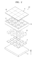
- FIG. 2 is an exploded perspective view illustrating an embodiment of an expressing unit 200 of FIG. 1 .
- an embodiment of the expressing unit 200 may include a substrate SB, a partition wall WL, and a pressure providing part, a fluid FD, and a tactile sensation providing layer TS.
- the substrate SB may be a flat insulating substrate.
- the substrate SB may include or be formed of glass, plastic or ceramic, for example.
- the partition wall WL is disposed on the substrate SB.
- the partition wall WL defines active regions AR based on partitioned inner spaces defined therein.
- the active regions AR may be spatially separated from each other by the partition wall WL.
- the active regions AR may be partitioned substantially in a matrix form.
- the pressure providing part may generate initial pressure by an electrical signal.
- the pressure providing part may include piezoelectric elements PZ.
- the piezoelectric elements PZ are disposed on the substrate SB.
- the piezoelectric elements PZ may be disposed in the active regions AR, respectively.
- Each of the piezoelectric elements PZ may be mechanically modified by a voltage applied thereto.
- each of the piezoelectric elements PZ may receive a voltage, and a volume of each of the piezoelectric elements PZ may thereby expand substantially in a first direction DR1 substantially perpendicular to a top surface of the substrate SB.
- the initial pressure may occur substantially in the first direction DR1 by the volume expansion of the piezoelectric elements PZ.
- the piezoelectric elements PZ may include or be formed of aluminum orthophosphate (AlPO 4 ), quartz, Rochelle salt, topaz, gallium orthophosphate (GaPO 4 ), lanthanum-gallium silicate (La 3 Ga 5 SiO 14 ), barium titanate (BaTiO 3 ), bismuth titanate (Bi 4 Ti 3 O 12 ), lead titanate (PbTiO 3 ), zinc oxide (ZnO), zirconium-lead titanate
- the fluid FD may be disposed on the piezoelectric elements PZ.
- the fluid FD may be disposed in each of the active regions AR.
- the fluid FD may generate a fluidic pressure at an initial pressure.
- the fluid FD may provide the fluidic pressure to the tactile sensation providing layer TS substantially in the first direction DR1 based on the mechanical modification of the piezoelectric element PZ.
- the tactile sensation providing layer TS may be disposed on the partition wall WL.
- the tactile sensation providing layer TS may protrude substantially in the first direction DR1 by the fluidic pressure of the fluid FD.
- the tactile sensation providing layer TS may include a plurality of unit regions UR respectively corresponding to the active regions AR.
- the unit regions UR may protrude independently of each other substantially in the first direction DR1 by the fluids FD respectively disposed in the active regions AR.
- the tactile sensation providing layer TS may include or be formed of a flexible material.
- the tactile sensation providing layer TS may include or be formed of plastic resin or a polymer film.
- the user may recognize the tactile sensation information through the tactile sensation providing layer TS.
- FIGS. 3 to 5 are perspective views illustrating portions of embodiments of the expressing unit according to the invention.
- an embodiment of the expressing unit 200 may further include a first electrode EL1 and a second electrode EL2.
- the first electrode EL1 and the second electrode EL2 may be disposed on the substrate SB.
- the first electrode EL1 and the second electrode EL2 may be disposed in each of the active regions AR.
- the first electrode EL1 may be connected to one terminal of a corresponding piezoelectric element PZ of the piezoelectric elements PZ.
- the second electrode EL2 may be connected to another terminal of the corresponding piezoelectric element PZ.
- the first electrode EL1 may be disposed on a top surface of the corresponding piezoelectric element PZ.
- the second electrode EL2 may be opposite to the first electrode EL1 with the corresponding piezoelectric element PZ therebetween.
- the second electrode EL2 may be disposed under the corresponding piezoelectric element PZ.
- a first voltage may be applied to the first electrode EL1, and a second voltage may be applied to the second electrode EL2.
- the volume of the corresponding piezoelectric element PZ connected to the first and second electrode EL1 and EL2 may expand or shrink substantially in the first direction DR1 by a voltage difference between the first voltage and the second voltage.
- an alternative embodiment of the expressing unit 200 may further include a first electrode EL1 and a second electrode EL2.
- the first electrode EL1 and the second electrode EL2 may be disposed on the substrate SB.
- the first electrode EL1 and the second electrode EL2 may be disposed in each of the active regions AR.
- the first electrode EL1 may be connected to one terminal of a corresponding piezoelectric element PZ of the piezoelectric elements PZ.
- the second electrode EL2 may be connected to another terminal of the corresponding piezoelectric element PZ.
- the first electrode EL1 may be disposed at a side of the corresponding piezoelectric element PZ.
- the second electrode EL2 may be opposite to the first electrode EL1 with the corresponding piezoelectric element PZ therebetween.
- the second electrode EL2 may be disposed at another side of the corresponding piezoelectric element PZ.
- a first voltage may be applied to the first electrode EL1, and a second voltage may be applied to the second electrode EL2.
- the volume of the corresponding piezoelectric element PZ connected to the first and second electrode EL1 and EL2 may expand or shrink substantially in the first direction DR1 by a voltage difference between the first voltage and the second voltage.
- another alternative embodiment of the expressing unit 200 may further include a first electrode EL1 and a second electrode EL2.
- the first electrode EL1 and the second electrode EL2 may be disposed on the substrate SB.
- the first electrode EL1 and the second electrode EL2 may extend in different directions from each other.
- the extending directions of the first and second electrodes EL1 and EL2 may be substantially parallel to the top surface of the substrate SB.
- the first electrode EL1 may be connected to the piezoelectric elements PZ arranged substantially in a column direction
- the second electrode EL2 may be connected to the piezoelectric elements PZ arranged substantially in a row direction.
- the piezoelectric elements PZ may be arranged along a plurality of rows substantially parallel to the row direction and a plurality of columns substantially parallel to the column direction.
- a plurality of first electrodes EL1 may be disposed or provided to respectively correspond to the plurality of columns and a plurality of second electrodes EL2 may be provided to respectively correspond to the plurality of rows.
- the partition wall WL may be disposed on the first electrode EL1 and EL2.
- the first electrode EL1 may be connected to one terminal of a corresponding piezoelectric element PZ.
- the second electrode EL2 may be connected to another terminal of the corresponding piezoelectric element PZ.
- the first electrode EL1 may be disposed on a top surface of the piezoelectric element PZ.
- the second electrode EL2 may be opposite to the first electrode EL1 with the piezoelectric element PZ therebetween. In one embodiment of the invention, for example, the second electrode EL2 may be disposed under the piezoelectric element PZ.
- a first voltage may be applied to the first electrode EL1, and a second voltage may be applied to the second electrode EL2.
- the volume of the piezoelectric element PZ connected to the first and second electrode EL1 and EL2 may expand or shrink substantially in the first direction DR1 by a voltage difference between the first voltage and the second voltage.
- the invention is not limited to the embodiments described above with reference to FIGS. 3 to 5 .
- the shapes of the piezoelectric element PZ and the first and second electrodes EL1 and EL2 may be variously modified under the condition that the first and second electrodes EL1 and EL2 are respectively connected to one terminal and another terminal of the piezoelectric element PZ.
- an embodiment of the invention in which the first and second electrodes EL1 and EL2 have the shapes shown in FIG. 3 , will be described in greater detail for convenience of description.
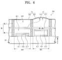
- FIG. 6 is a cross-sectional view illustrating an embodiment of an expressing unit 200 of FIG. 1 , according to the invention.
- FIG. 6 illustrates two active regions of an embodiment of an expressing unit 200 including a first active region AR1 and a second active region AR2.
- FIG. 6 shows an embodiment of an expressing unit 200 when the first active region AR1 applies pressure to the tactile sensation providing layer TS, and the second active region AR2 does not apply pressure to the tactile sensation providing layer TS.
- an embodiment of the expressing unit 200 may further include a hydrogen storage alloy HT.
- the hydrogen storage alloy HT may absorb or release hydrogen based on an applied pressure thereto. In such an embodiment, when the pressure is applied to the hydrogen storage alloy HT, the hydrogen storage alloy HT may release the hydrogen. In such an embodiment, when the pressure is not applied to the hydrogen storage alloy HT, the hydrogen storage alloy may absorb or restore the hydrogen. The release and absorption of the hydrogen of the hydrogen storage alloy HT is reversible.
- the hydrogen released from the hydrogen storage alloy HT applies pressure to the tactile sensation providing layer TS, and thus, the tactile sensation providing layer TS may protrude.
- the hydrogen storage alloy HT may be homogeneous or heterogeneous.
- the hydrogen storage alloy HT may include a magnesium-based hydrogen storage alloy (e.g., Mg 2 Cu or Mg 2 Ni), a rare-earth metal-based hydrogen storage alloy (e.g., LaNi 5 or MnNi 5 ), a titanium-based hydrogen storage alloy (e.g., TiFe, TiCo, TiMn, or TiCr 2 ), a zirconium-based hydrogen storage alloy (e.g., ZrMn 2 ), for a combination thereof.
- a magnesium-based hydrogen storage alloy e.g., Mg 2 Cu or Mg 2 Ni
- a rare-earth metal-based hydrogen storage alloy e.g., LaNi 5 or MnNi 5
- a titanium-based hydrogen storage alloy e.g., TiFe, TiCo, TiMn, or TiCr 2
- zirconium-based hydrogen storage alloy e.g., ZrMn 2
- the hydrogen storage alloy HT may have a maximum hydrogen release amount of about 1.4 ⁇ 10 6 cubic micrometer( ⁇ m 3 ) per a unit volume of 100 ⁇ 100 ⁇ 10 ⁇ m 3 . Since a resolution of tactile sensation of a person (e.g., a human finger) is generally about 40 ⁇ m, the hydrogen storage alloy HT having the unit volume may provide recognizable tactile sensation information to the person.
- the expressing unit 200 may include a plurality of hydrogen storage alloys HT.
- the plurality of hydrogen storage alloys HT may be spaced apart from each other and may correspond to the active regions AR, respectively.
- the hydrogen storage alloys HT may include a first hydrogen storage alloy HT1 corresponding to the first active region AR1 and a second hydrogen storage alloy HT2 corresponding to the second active region AR2.
- the partition wall WL may include a first partition wall WL1 and a second partition wall WL2.
- the first partition wall WL1 may be disposed between the substrate SB and the hydrogen storage alloy HT to define a first space SP1 that is sealed.
- the second partition wall WL may be disposed between the hydrogen storage alloy HT and the tactile sensation providing layer TS to define a second space SP2 that is sealed.
- the fluid FD may be a gas.
- the fluid FD may include an inert gas and hydrogen.
- the inert gas may fill the first space SP1.
- the inert gas may include at least one of 18-group elements and may have very low reactivity. Thus, the inert gas may not generate a compound.
- the hydrogen may fill the second space SP2 or may be stored in the hydrogen storage alloy HT.
- a driving mechanism of the first and second active regions AR1 and AR2 of the expressing unit shown in FIG. 6 will be described hereinafter.
- different voltages from each other may be applied to the first electrode EL1 and the second electrode EL2 of the first active region AR1, respectively, such that a volume of a piezoelectric element PZ1 of the first active region AR1 may be expanded substantially in the first direction DR1 by a voltage difference between the voltages applied to the first and second electrodes EL1 and EL2.
- the inert gas in the first space SP1 applies pressure to the first hydrogen storage alloy HT1.
- the first hydrogen storage alloy HT1 releases hydrogen into the second space SP2 by the pressure of the inert gas, and the hydrogen thereby applies pressure to a corresponding unit region UR1 of the tactile sensation providing layer TS.
- the unit region UR1 may protrude substantially in the first direction DR1 by the pressure applied by the hydrogen. Users may recognize information expressed by the protruding unit region UR1 through their tactile sensation.
- voltages equal to each other may be applied to the first electrode EL1 and the second electrode EL2 of the second active region AR2. Since a voltage difference does not occur between the first and second electrodes EL1 and EL2 of the second active region AR2, a volume of a piezoelectric element PZ2 of the second active region AR2 may not be expanded.
- the inert gas filling the first space SP1 of the second active region AR2 does not apply pressure to the second hydrogen storage alloy HT2, such that the second hydrogen storage alloy HT2 may restore hydrogen in the second space SP2 of the second active region AR2.
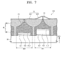
- FIG. 7 is a cross-sectional view illustrating an alternative embodiment of an expressing unit 200 of FIG. 1 according to the invention.
- FIG. 7 illustrates two active regions including a first active region AR1 and a second active region AR2 as an example.
- the first active region AR1 applies pressure to the tactile sensation providing layer TS, and the second active region AR2 does not apply pressure to the tactile sensation providing layer TS.
- the partition wall WL may include an upper partition wall WLU and a lower partition wall WLL.
- the lower partition wall WLL may be disposed on the substrate SB.
- the upper partition wall WLU may be disposed between the lower partition wall WLL and the tactile sensation providing layer TS.
- the upper partition wall WLU and the lower partition wall WLL may be integrally formed as a single unitary and indivisible unit.
- the partition wall WL may include only the upper partition wall WLU.
- a width of the upper partition wall WLU may become progressively less from a top of the upper partition wall WLU toward of a bottom of the upper partition wall WLU.
- An area of a region exposed by the top of the upper partition wall WLU may be smaller than an area of a region exposed by the bottom of the upper partition wall WLU when viewed from a plan view.
- the fluid FD may be a liquid.
- the fluid FD may be oil.
- a height of a top surface of the fluid FD may be controlled based on an expansion of the volume of piezoelectric elements PZ1 and PZ2.
- a maximum height of the top surface of the fluid FD may be substantially equal to or lower than the top of the upper partition wall WLU.
- the expressing unit 200 may further include a protrusion PD.
- the protrusion PD may be disposed between the top surface of the fluid FD and the tactile sensation providing layer TS.
- the protrusion PD may be moved by the fluid pressure of the fluid FD (e.g., movement of the top surface of the fluid FD), and thus, the tactile sensation providing layer TS may protrude.
- the protrusion PD may include or be formed of a material having a relatively great buoyance.
- a driving mechanism of the first and second active regions AR1 and AR2 of the expressing unit shown in FIG. 7 will be described hereinafter.
- different voltages from each other may be applied to the first electrode EL1 and the second electrode EL2 of the first active region AR1, such that a volume of the piezoelectric element PZ1 of the first active region AR1 may be expanded substantially in the first direction DR1 by a voltage difference between the voltages applied to the first and second electrodes EL1 and EL2.
- the volume of the piezoelectric element PZ1 is expanded, the height of the top surface of the fluid FD ascends and the protrusion PD applies pressure to a corresponding unit region UR1 of the tactile sensation providing layer TS.
- the unit region UR1 may protrude substantially in the first direction DR1 by the pressure applied by fluid FD and the protrusion PD. Users may recognize information expressed by the protruding unit region UR1 through their tactile sensation.
- voltages equal to each other may be applied to the first electrode EL1 and the second electrode EL2 of the second active region AR2. Since a voltage difference does not occur between the first and second electrodes EL1 and EL2 of the second active region AR2, a volume of the piezoelectric element PZ2 of the second active region AR2 may not be expanded. Accordingly, the height of the top surface of the fluid FD may be maintained.
- an expanded piezoelectric element PZ2 may shrink, and the height of the top surface of the fluid FD may descend.
- a top of the protrusion PD may be disposed to be equal to or lower than the top surface of the upper partition wall WLU.
- pressure is not applied to the unit region UR2, which correspond to the second active region AR2, of the tactile sensation providing layer UR2.
- the unit region UR2 does not protrude. Users may recognize information expressed by the non-protruding unit region UR2 through their tactile sensation.
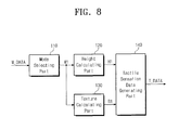
- FIG. 8 is a schematic block diagram illustrating an embodiment of the driving unit 100 of FIG. 1 .
- the driving unit 100 may include a mode selecting part 110, a height calculating part 120, a texture calculating part 130 and a tactile sensation data generating part 140.
- the mode selecting part 110 receives the image data M_DATA from an external system.
- the mode selecting part 110 selects at least one of shape information, color information and gradation information, which are included in the image data M_DATA.
- the expressing unit 200 When the expressing unit 200 provides the tactile sensation information to the user, the same information as the information included in the image data M_DATA is not provided to the user.
- the tactile sensation data generating part 140 may generate tactile sensation data T_DATA with respect to the shape information and may output the generated tactile sensation data T_DATA to the expressing unit 200.
- the user may recognize the tactile sensation information corresponding to the tactile sensation data T_DATA.
- the expressing unit 200 may provide the tactile sensation information using the height or the texture of the tactile sensation providing layer TS.
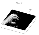
- FIG. 9 is a diagram illustrating an embodiment of an electronic device 1000 on which a face shape of a person is expressed.
- the expressing unit 200 may express a stereoscopic face shape of the person.
- the user recognizes eye, nose and mouth shapes and roughness of the skin which are expressed on the expressing unit 200 through the tactile sensation. As a result, the user may recognize the stereoscopic face shape of the person expressed on the expressing unit 200.
- the expressing unit 200 may express the color information or the gradation information and the user may recognize the color or gradation information expressed on the expressing unit 200.
- the expressing unit 200 may express the color or gradation information through the height or texture of the tactile sensation providing layer TS.
- FIG. 10 is a cross-sectional view illustrating an embodiment of an expressing unit which expresses a color and a gradation based on a height of a tactile sensation providing layer.
- FIG. 10 other elements, except the tactile sensation providing layer TS, of the expressing unit 200 are simplified as an expression substrate 500, for convenience of illustration.
- a unit region UR-A having the maximum height of the tactile sensation providing layer TS may be defined as a unit region expressing a red color
- a unit region UR-G having the minimum height of the tactile sensation providing layer TS may be defined as a unit region expressing a blue color
- the unit region UR-G having the minimum height of the tactile sensation providing layer TS may be a non-protruding unit region.
- unit regions UR-B to UR-F having heights between the maximum height and the minimum height may be defined as unit regions expressing colors between the red color and the blue color in a color coordinate.
- the user may sense the heights of the tactile sensation providing layer TS through the tactile sensation of the user to recognize the color.
- the user may recognize the color changed from the red color to the blue color as a touch position is moved from the left to the right of FIG. 10 .
- the unit region UR-A having the maximum height of the tactile sensation providing layer TS may be defined as a unit region expressing a white gradation
- the unit region UR-G (e.g., the non-protruding unit region) having the minimum height of the tactile sensation providing layer TS may be defined as a unit region expressing a black gradation
- unit regions UR-B to UR-F having heights between the maximum height and the minimum height may be defined as unit regions expressing gradations between the white gradation and the black gradation.
- the user may sense the heights of the tactile sensation providing layer TS through the tactile sensation of the user to recognize the gradation. In FIG. 10 , the user may recognize the gradation changed from the white gradation to the black gradation as a touch position is moved from the left to the right of FIG. 10 .
- FIGS. 11A to 11C are plan views illustrating an embodiment of an expressing unit that expresses a color and a gradation based on a texture of a tactile sensation providing layer.
- FIGS. 11A to 11C illustrate unit regions UR-A to UR-I of the tactile sensation providing layer TS which are arranged in a 3x3 matrix form.
- unit regions in which a reference designator "O" is expressed are defined as protruding unit regions, and unit regions in which the reference designator “O” is not expressed are defined as non-protruding unit regions. Protruding heights of the unit regions expressed by the reference designator "O" may be substantially equal to each other.
- FIG. 11A when a density of the protruding unit regions is high, the user may recognize a rough texture through the tactile sensation.
- FIG. 11C a density of the protruding unit regions is low, and thus, the user may recognize a smooth texture through the tactile sensation.
- FIG. 11B the user may recognize a texture having a roughness between the roughness of FIG. 11A and the roughness of FIG. 11C .
- the protruding regions having the maximum density may be defined as expressing a red color
- the protruding regions having the minimum density may be defined as expressing a blue color
- the protruding regions having a density between the maximum density and the minimum density may be defined as expressing a color between the red color and the blue color.
- the user may sense a roughness of the tactile sensation providing layer TS through the tactile sensation to recognize the color.
- the user may recognize the color changed from the red color to the blue color as the user senses from the unit regions of FIG. 11A to the unit regions of FIG. 11C .
- the protruding regions having the maximum density may be defined as expressing the white gradation
- the protruding regions having the minimum density may be defined as expressing the black gradation
- the protruding regions having a density between the maximum density and the minimum density may be defined as expressing a gradation between the white gradation and the black gradation.
- the user may sense the roughness of the tactile sensation providing layer TS through the tactile sensation to recognize the gradation.
- the user may recognize the gradation changed from the white gradation to the black gradation as the user senses from the unit regions of FIG. 11A to the unit regions of FIG. 11C .
- the height calculating part 120 receives the information M1 selected from the mode selecting part 110.
- the height calculating part 120 may determine heights of the unit regions UR of the tactile sensation providing layer TS respectively corresponding to the active region AR on the basis of the selected information M1.
- the height calculating part 120 may output a first signal H1 that includes data indicating the determined heights of the unit regions UR.
- the texture calculating part 130 receives the information M1 selected from the mode selecting part 110.
- the texture calculating part 130 may determine a texture of the tactile sensation providing layer TS based on the selected information M1.
- the texture calculating part 130 may determine the number of protruding unit regions among a predetermined number of the unit regions.
- the texture calculating part 130 may output a second signal R1 that includes data indicating the number of protruding unit regions among the predetermined number of unit regions.
- the tactile sensation data generating part 140 receives the first signal H1 and the second signal R1.
- the tactile sensation data generating part 140 the tactile sensation data T_DATA based on the height and the texture of the tactile sensation providing layer TS.
- the tactile sensation data generating part 140 outputs the tactile sensation data T_DATA to the expressing unit 200 of FIG. 1 .
- FIG. 12 is a flowchart illustrating an embodiment of a method for providing information of an electronic device.
- an embodiment of a method for providing the information of the electronic device includes selecting one of expression related information included in image data (S1) and expressing tactile sensation information corresponding to the selected information by protruding at least a portion of an outer surface of an electronic device (S2).
- the information included in the image data may include shape information, color information and gradation information.
- the tactile sensation providing layer TS of the expressing unit 200 may include a plurality of unit regions UR, and the unit regions UR may protrude by the piezoelectric elements PZ and the fluid FD.
- the tactile sensation information may be expressed using heights of the unit regions UR and the number of the protruding unit regions among the plurality of unit regions.
- An embodiment of the expressing unit 200 may express the shape, color or gradation information as described with reference to FIGS. 8 to 11 .
- the user may recognize the shape, color or gradation information as described with reference to FIGS. 8 to 11 .
- the electronic device may express the tactile sensation information and the user may recognize the expressed information through the tactile sensation.
- the tactile sensation information corresponding to the shape, color or gradation information of the image data may be expressed by an embodiment of the method for providing the information of the electronic device described above, according to the invention.
Landscapes
- Engineering & Computer Science (AREA)
- General Engineering & Computer Science (AREA)
- Theoretical Computer Science (AREA)
- Physics & Mathematics (AREA)
- General Physics & Mathematics (AREA)
- Human Computer Interaction (AREA)
- Health & Medical Sciences (AREA)
- Audiology, Speech & Language Pathology (AREA)
- General Health & Medical Sciences (AREA)
- Business, Economics & Management (AREA)
- Educational Administration (AREA)
- Educational Technology (AREA)
- User Interface Of Digital Computer (AREA)
Abstract
Description
- The invention relates to an electronic device and a method for providing information thereof and, more particularly, to an electronic device that provides tactile sensation information and a method for providing information thereof.
- Display devices provide visual information to a user. The display devices may include a liquid crystal display device, an organic light-emitting display device, and a plasma display device, for example. Generally, a display device may include a flat display panel for displaying an image.
- The user recognizes the image displayed from the flat display panel only through the sense of sight but does not recognize the image through the sense of touch.
- Embodiments of the invention seek to provide an electronic device that provides tactile sensation information to a user.
- Embodiments of the invention also seek to provide a method for providing information of an electronic device expressing tactile sensation information corresponding to shape information, color information, and gradation information included in image data.
- In an embodiment of the invention, an electronic device includes a pressure providing part, a fluid, and a tactile sensation providing layer. In such an embodiment, the pressure providing part may generate an initial pressure in response to an electrical signal, the fluid may generate a fluidic pressure corresponding to the initial pressure in each of active regions partitioned from each other, and the tactile sensation providing layer may be configured to protrude by the fluidic pressure.
- In an embodiment, the pressure providing part may include a plurality of piezoelectric elements disposed in the active regions, and each of the piezoelectric elements may be mechanically modified by the electrical signal.
- In an embodiment, the electronic device may further include: a first electrode connected to one terminal of a piezoelectric element of the piezoelectric elements; and a second electrode connected to another terminal of the piezoelectric element of the piezoelectric elements.
- In an embodiment, the electronic device may further include: a hydrogen storage alloy which absorbs or releases hydrogen according to pressure applied thereto.
- In an embodiment, the electronic device may further include: a substrate; and a partition wall disposed on the substrate and defining the active regions. In such an embodiment, the partition wall may include: a first partition wall disposed between the substrate and the hydrogen storage alloy to define a first space which is sealed; and a second partition wall disposed between the hydrogen storage alloy and the tactile sensation providing layer to define a second space which is sealed.
- In an embodiment, the fluid may include: an inert gas which fills the first space; and hydrogen which fills the second space or stored in the hydrogen storage alloy.
- In an alternative embodiment, the fluid may be liquid.
- In an embodiment, a width of a region of the partition wall may become progressively less toward a bottom of the region.
- In an embodiment, an area of a region exposed by a top of the partition wall may be smaller than an area of a region exposed by a bottom of the partition wall when viewed from a plan view.
- In an embodiment, the electronic device may further include: a protrusion disposed between a surface of the fluid and the tactile sensation providing layer. In such an embodiment, the protrusion may be moved by the fluidic pressure to protrude the tactile sensation providing layer.
- In an embodiment, the electronic device may further include: a driving unit which receives image data, converts the image data into tactile sensation data, and outputs the tactile sensation data to an expressing unit.
- In an embodiment, the expressing unit may express tactile sensation information corresponding to the tactile sensation data and may include the pressure providing part, the fluid, and the tactile sensation providing layer.
- In an embodiment, the driving unit may include a mode selecting part, a height calculating part, a texture calculating part, and a tactile sensation data generating part.
- In an embodiment, the mode selecting part may select at least one of shape information, color information, and gradation information which are included in the image data.
- In an embodiment, the height calculating part may determine heights of unit regions, respectively corresponding to the active regions, of the tactile sensation providing layer.
- In an embodiment, the texture calculating part may determine the number of protruding unit regions among the unit regions of the tactile sensation providing layer to determine a texture of the tactile sensation providing layer.
- In an embodiment, the tactile sensation data generating part may generate the tactile sensation data based on the heights and the texture of the tactile sensation providing layer.
- In another embodiment, a method for providing information of an electronic device may include: selecting at least one of expression related information included in image data; and expressing tactile sensation information corresponding to the selected information by protruding at least a portion of an outer surface of the electronic device.
- In an embodiment, the expression related information of the image data may include shape information, color information, and gradation information.
- In an embodiment, the electronic device may include a plurality of unit regions configured to protrude by signals applied thereto. In such an embodiment, expressing the tactile sensation information may include: expressing the tactile sensation information using heights of the unit regions and the number of protruding unit regions among the plurality of unit regions.
- At least some of the above and other features of the invention are set-out in the claims.
- The above and other feature of the invention will be made more apparent by describing in further detail embodiments thereof with reference to the accompanying drawings, in which:
-
FIG. 1 is a schematic block diagram illustrating an embodiment of an electronic device according to the invention; -
FIG. 2 is an exploded perspective view illustrating an embodiment of an expressing unit ofFIG. 1 ; -
FIGS. 3 to 5 are perspective views illustrating portions of embodiments of the expressing unit according to the invention; -
FIG. 6 is a cross-sectional view illustrating an embodiment of the expressing unit ofFIG. 1 , according to the invention; -
FIG. 7 is a cross-sectional view illustrating an alternative embodiment of the expressing unit ofFIG. 1 , according to the invention; -
FIG. 8 is a schematic block diagram illustrating an embodiment of a driving unit ofFIG. 1 ; -
FIG. 9 is a diagram illustrating an embodiment of an electronic device on which a face shape of a person is expressed; -
FIG. 10 is a cross-sectional view illustrating an embodiment of an expressing unit that expresses a color and a gradation based on a height of a tactile sensation providing layer; -
FIGS. 11A to 11C are plan views illustrating an embodiment of an expressing unit that expresses a color and a gradation based on a texture of a tactile sensation providing layer; and -
FIG. 12 is a flowchart illustrating an embodiment of a method for providing information of an electronic device. - The invention will now be described more fully hereinafter with reference to the accompanying drawings, in which various embodiments are shown. This invention may, however, be embodied in many different forms, and should not be construed as limited to the embodiments set forth herein. Rather, these embodiments are provided so that this disclosure will be thorough and will convey the scope of the invention to those skilled in the art. Like reference numerals refer to like elements throughout.
- It will be understood that when an element is referred to as being "on" another element, it can be directly on the other element or intervening elements may be present therebetween. In contrast, when an element is referred to as being "directly on" another element, there are no intervening elements present.
- It will be understood that, although the terms "first," "second," "third" etc. may be used herein to describe various elements, components, regions, layers and/or sections, these elements, components, regions, layers and/or sections should not be limited by these terms. These terms are only used to distinguish one element, component, region, layer or section from another element, component, region, layer or section. Thus, "a first element," "component," "region," "layer" or "section" discussed below could be termed a second element, component, region, layer or section without departing from the teachings herein.
- The terminology used herein is for the purpose of describing particular embodiments only and is not intended to be limiting. As used herein, the singular forms "a," "an," and "the" are intended to include the plural forms, including "at least one," unless the content clearly indicates otherwise. "Or" means "and/or." As used herein, the term "and/or" includes any and all combinations of one or more of the associated listed items. It will be further understood that the terms "comprises" and/or "comprising," or "includes" and/or "including" when used in this specification, specify the presence of stated features, regions, integers, steps, operations, elements, and/or components, but do not preclude the presence or addition of one or more other features, regions, integers, steps, operations, elements, components, and/or groups thereof.
- Furthermore, relative terms, such as "lower" or "bottom" and "upper" or "top," may be used herein to describe one element's relationship to another element as illustrated in the Figures. It will be understood that relative terms are intended to encompass different orientations of the device in addition to the orientation depicted in the Figures. For example, if the device in one of the figures is turned over, elements described as being on the "lower" side of other elements would then be oriented on "upper" sides of the other elements. The term "lower," can therefore, encompasses both an orientation of "lower" and "upper," depending on the particular orientation of the figure. Similarly, if the device in one of the figures is turned over, elements described as "below" or "beneath" other elements would then be oriented "above" the other elements. The terms "below" or "beneath" can, therefore, encompass both an orientation of above and below.
- "About" or "approximately" as used herein is inclusive of the stated value and means within an acceptable range of deviation for the particular value as determined by one of ordinary skill in the art, considering the measurement in question and the error associated with measurement of the particular quantity (i.e., the limitations of the measurement system). For example, "about" can mean within one or more standard deviations, or within ± 30%, 20%, 10%, 5% of the stated value.
- Unless otherwise defined, all terms (including technical and scientific terms) used herein have the same meaning as commonly understood by one of ordinary skill in the art to which this disclosure belongs. It will be further understood that terms, such as those defined in commonly used dictionaries, should be interpreted as having a meaning that is consistent with their meaning in the context of the relevant art and the present disclosure, and will not be interpreted in an idealized or overly formal sense unless expressly so defined herein.
- Embodiments of the invention are described herein with reference to cross section illustrations that are schematic illustrations of idealized embodiments. As such, variations from the shapes of the illustrations as a result, for example, of manufacturing techniques and/or tolerances, are to be expected. Thus, embodiments described herein should not be construed as limited to the particular shapes of regions as illustrated herein but are to include deviations in shapes that result, for example, from manufacturing. For example, a region illustrated or described as flat may, typically, have rough and/or nonlinear features. Moreover, sharp angles that are illustrated may be rounded. Thus, the regions illustrated in the figures are schematic in nature and their shapes are not intended to illustrate the precise shape of a region and are not intended to limit the scope of the present claims.
- Hereinafter, embodiments of the invention will be described in further detail with reference to the accompanying drawings.
-
FIG. 1 is a schematic block diagram illustrating an embodiment of anelectronic device 1000 according to the invention. - Referring to
FIG. 1 , an embodiment of theelectronic device 1000 includes adriving unit 100 and an expressingunit 200. - The expressing
unit 200 is driven by the drivingunit 100. The drivingunit 100 receives image data M_DATA and converts the image data M_DATA into tactile sensation data T_DATA. The drivingunit 100 will be described later in greater detail. - The expressing
unit 200 receives the tactile sensation data T_DATA and expresses tactile sensation information corresponding to the tactile sensation data T_DATA. A user may recognize through the tactile sensation information a shape, a color and a gradation that the expressingunit 200 expresses. -
FIG. 2 is an exploded perspective view illustrating an embodiment of an expressingunit 200 ofFIG. 1 . - Referring to
FIG. 2 , an embodiment of the expressingunit 200 may include a substrate SB, a partition wall WL, and a pressure providing part, a fluid FD, and a tactile sensation providing layer TS. - The substrate SB may be a flat insulating substrate. The substrate SB may include or be formed of glass, plastic or ceramic, for example.
- The partition wall WL is disposed on the substrate SB. The partition wall WL defines active regions AR based on partitioned inner spaces defined therein. The active regions AR may be spatially separated from each other by the partition wall WL. The active regions AR may be partitioned substantially in a matrix form.
- The pressure providing part may generate initial pressure by an electrical signal. The pressure providing part may include piezoelectric elements PZ.
- The piezoelectric elements PZ are disposed on the substrate SB. The piezoelectric elements PZ may be disposed in the active regions AR, respectively. Each of the piezoelectric elements PZ may be mechanically modified by a voltage applied thereto. In an embodiment of the invention, each of the piezoelectric elements PZ may receive a voltage, and a volume of each of the piezoelectric elements PZ may thereby expand substantially in a first direction DR1 substantially perpendicular to a top surface of the substrate SB. The initial pressure may occur substantially in the first direction DR1 by the volume expansion of the piezoelectric elements PZ.
- The piezoelectric elements PZ may include or be formed of aluminum orthophosphate (AlPO4), quartz, Rochelle salt, topaz, gallium orthophosphate (GaPO4), lanthanum-gallium silicate (La3Ga5SiO14), barium titanate (BaTiO3), bismuth titanate (Bi4Ti3O12), lead titanate (PbTiO3), zinc oxide (ZnO), zirconium-lead titanate
- (Pb[ZrxTi1-x]O3, 0<x<1; PZT), lanthanum-bismuth titanate ([Bi4-xLax]Ti3O12, 0<x<1; BLT), tin oxide (SnO2), kalium niobate (KNbO3), lithium niobate (LiNbO3), lithium tantalate (LiTaO3), sodium tungstate (Na2WO3), sodium-barium niobate (Ba2NaNb5O5), kalium-lead niobate (Pb2KNb5O15), sodium-kalium niobate (KNaNb5O5), bismuth ferrite (BiFeO3), or a combination thereof.
- The fluid FD may be disposed on the piezoelectric elements PZ. The fluid FD may be disposed in each of the active regions AR. The fluid FD may generate a fluidic pressure at an initial pressure. In an embodiment of the invention, the fluid FD may provide the fluidic pressure to the tactile sensation providing layer TS substantially in the first direction DR1 based on the mechanical modification of the piezoelectric element PZ.
- The tactile sensation providing layer TS may be disposed on the partition wall WL. The tactile sensation providing layer TS may protrude substantially in the first direction DR1 by the fluidic pressure of the fluid FD. The tactile sensation providing layer TS may include a plurality of unit regions UR respectively corresponding to the active regions AR. The unit regions UR may protrude independently of each other substantially in the first direction DR1 by the fluids FD respectively disposed in the active regions AR.
- The tactile sensation providing layer TS may include or be formed of a flexible material. In one embodiment of the invention, for example, the tactile sensation providing layer TS may include or be formed of plastic resin or a polymer film.
- The user may recognize the tactile sensation information through the tactile sensation providing layer TS.
-
FIGS. 3 to 5 are perspective views illustrating portions of embodiments of the expressing unit according to the invention. - Referring to
FIGS. 2 and3 , an embodiment of the expressingunit 200 may further include a first electrode EL1 and a second electrode EL2. - The first electrode EL1 and the second electrode EL2 may be disposed on the substrate SB. The first electrode EL1 and the second electrode EL2 may be disposed in each of the active regions AR.
- The first electrode EL1 may be connected to one terminal of a corresponding piezoelectric element PZ of the piezoelectric elements PZ. The second electrode EL2 may be connected to another terminal of the corresponding piezoelectric element PZ.
- The first electrode EL1 may be disposed on a top surface of the corresponding piezoelectric element PZ. The second electrode EL2 may be opposite to the first electrode EL1 with the corresponding piezoelectric element PZ therebetween. In one embodiment, for example, the second electrode EL2 may be disposed under the corresponding piezoelectric element PZ.
- A first voltage may be applied to the first electrode EL1, and a second voltage may be applied to the second electrode EL2. The volume of the corresponding piezoelectric element PZ connected to the first and second electrode EL1 and EL2 may expand or shrink substantially in the first direction DR1 by a voltage difference between the first voltage and the second voltage.
- Referring to
FIGS. 2 and4 , an alternative embodiment of the expressingunit 200 may further include a first electrode EL1 and a second electrode EL2. - The first electrode EL1 and the second electrode EL2 may be disposed on the substrate SB. The first electrode EL1 and the second electrode EL2 may be disposed in each of the active regions AR.
- The first electrode EL1 may be connected to one terminal of a corresponding piezoelectric element PZ of the piezoelectric elements PZ. The second electrode EL2 may be connected to another terminal of the corresponding piezoelectric element PZ.
- The first electrode EL1 may be disposed at a side of the corresponding piezoelectric element PZ. The second electrode EL2 may be opposite to the first electrode EL1 with the corresponding piezoelectric element PZ therebetween. The second electrode EL2 may be disposed at another side of the corresponding piezoelectric element PZ.
- A first voltage may be applied to the first electrode EL1, and a second voltage may be applied to the second electrode EL2. The volume of the corresponding piezoelectric element PZ connected to the first and second electrode EL1 and EL2 may expand or shrink substantially in the first direction DR1 by a voltage difference between the first voltage and the second voltage.
- Referring to
FIGS. 2 and5 , another alternative embodiment of the expressingunit 200 may further include a first electrode EL1 and a second electrode EL2. - The first electrode EL1 and the second electrode EL2 may be disposed on the substrate SB. The first electrode EL1 and the second electrode EL2 may extend in different directions from each other. In an embodiment of the invention, the extending directions of the first and second electrodes EL1 and EL2 may be substantially parallel to the top surface of the substrate SB.
- The first electrode EL1 may be connected to the piezoelectric elements PZ arranged substantially in a column direction, and the second electrode EL2 may be connected to the piezoelectric elements PZ arranged substantially in a row direction. The piezoelectric elements PZ may be arranged along a plurality of rows substantially parallel to the row direction and a plurality of columns substantially parallel to the column direction. In such an embodiment, a plurality of first electrodes EL1 may be disposed or provided to respectively correspond to the plurality of columns and a plurality of second electrodes EL2 may be provided to respectively correspond to the plurality of rows. The partition wall WL may be disposed on the first electrode EL1 and EL2.
- The first electrode EL1 may be connected to one terminal of a corresponding piezoelectric element PZ. The second electrode EL2 may be connected to another terminal of the corresponding piezoelectric element PZ.
- The first electrode EL1 may be disposed on a top surface of the piezoelectric element PZ. The second electrode EL2 may be opposite to the first electrode EL1 with the piezoelectric element PZ therebetween. In one embodiment of the invention, for example, the second electrode EL2 may be disposed under the piezoelectric element PZ.
- A first voltage may be applied to the first electrode EL1, and a second voltage may be applied to the second electrode EL2. The volume of the piezoelectric element PZ connected to the first and second electrode EL1 and EL2 may expand or shrink substantially in the first direction DR1 by a voltage difference between the first voltage and the second voltage.
- However, the invention is not limited to the embodiments described above with reference to
FIGS. 3 to 5 . In other embodiments of the invention, the shapes of the piezoelectric element PZ and the first and second electrodes EL1 and EL2 may be variously modified under the condition that the first and second electrodes EL1 and EL2 are respectively connected to one terminal and another terminal of the piezoelectric element PZ. Hereinafter, an embodiment of the invention, in which the first and second electrodes EL1 and EL2 have the shapes shown inFIG. 3 , will be described in greater detail for convenience of description. -
FIG. 6 is a cross-sectional view illustrating an embodiment of an expressingunit 200 ofFIG. 1 , according to the invention. -
FIG. 6 illustrates two active regions of an embodiment of an expressingunit 200 including a first active region AR1 and a second active region AR2.FIG. 6 shows an embodiment of an expressingunit 200 when the first active region AR1 applies pressure to the tactile sensation providing layer TS, and the second active region AR2 does not apply pressure to the tactile sensation providing layer TS. - Referring to
FIGS. 2 and6 , an embodiment of the expressingunit 200 may further include a hydrogen storage alloy HT. The hydrogen storage alloy HT may absorb or release hydrogen based on an applied pressure thereto. In such an embodiment, when the pressure is applied to the hydrogen storage alloy HT, the hydrogen storage alloy HT may release the hydrogen. In such an embodiment, when the pressure is not applied to the hydrogen storage alloy HT, the hydrogen storage alloy may absorb or restore the hydrogen. The release and absorption of the hydrogen of the hydrogen storage alloy HT is reversible. - In such an embodiment, the hydrogen released from the hydrogen storage alloy HT applies pressure to the tactile sensation providing layer TS, and thus, the tactile sensation providing layer TS may protrude.
- The hydrogen storage alloy HT may be homogeneous or heterogeneous. In one embodiment of the invention, for example, the hydrogen storage alloy HT may include a magnesium-based hydrogen storage alloy (e.g., Mg2Cu or Mg2Ni), a rare-earth metal-based hydrogen storage alloy (e.g., LaNi5 or MnNi5), a titanium-based hydrogen storage alloy (e.g., TiFe, TiCo, TiMn, or TiCr2), a zirconium-based hydrogen storage alloy (e.g., ZrMn2), for a combination thereof.
- The hydrogen storage alloy HT may have a maximum hydrogen release amount of about 1.4×10⁶ cubic micrometer(µm3) per a unit volume of 100×100×10 µm3. Since a resolution of tactile sensation of a person (e.g., a human finger) is generally about 40 µm, the hydrogen storage alloy HT having the unit volume may provide recognizable tactile sensation information to the person.
- The expressing
unit 200 may include a plurality of hydrogen storage alloys HT. The plurality of hydrogen storage alloys HT may be spaced apart from each other and may correspond to the active regions AR, respectively. The hydrogen storage alloys HT may include a first hydrogen storage alloy HT1 corresponding to the first active region AR1 and a second hydrogen storage alloy HT2 corresponding to the second active region AR2. - The partition wall WL may include a first partition wall WL1 and a second partition wall WL2.
- The first partition wall WL1 may be disposed between the substrate SB and the hydrogen storage alloy HT to define a first space SP1 that is sealed.
- The second partition wall WL may be disposed between the hydrogen storage alloy HT and the tactile sensation providing layer TS to define a second space SP2 that is sealed.
- The fluid FD may be a gas. The fluid FD may include an inert gas and hydrogen. The inert gas may fill the first space SP1. The inert gas may include at least one of 18-group elements and may have very low reactivity. Thus, the inert gas may not generate a compound. The hydrogen may fill the second space SP2 or may be stored in the hydrogen storage alloy HT.
- A driving mechanism of the first and second active regions AR1 and AR2 of the expressing unit shown in
FIG. 6 will be described hereinafter. - In such an embodiment, different voltages from each other may be applied to the first electrode EL1 and the second electrode EL2 of the first active region AR1, respectively, such that a volume of a piezoelectric element PZ1 of the first active region AR1 may be expanded substantially in the first direction DR1 by a voltage difference between the voltages applied to the first and second electrodes EL1 and EL2. When the volume of the piezoelectric element PZ1 is expanded, the inert gas in the first space SP1 applies pressure to the first hydrogen storage alloy HT1. The first hydrogen storage alloy HT1 releases hydrogen into the second space SP2 by the pressure of the inert gas, and the hydrogen thereby applies pressure to a corresponding unit region UR1 of the tactile sensation providing layer TS. The unit region UR1 may protrude substantially in the first direction DR1 by the pressure applied by the hydrogen. Users may recognize information expressed by the protruding unit region UR1 through their tactile sensation.
- In such an embodiment, voltages equal to each other may be applied to the first electrode EL1 and the second electrode EL2 of the second active region AR2. Since a voltage difference does not occur between the first and second electrodes EL1 and EL2 of the second active region AR2, a volume of a piezoelectric element PZ2 of the second active region AR2 may not be expanded. The inert gas filling the first space SP1 of the second active region AR2 does not apply pressure to the second hydrogen storage alloy HT2, such that the second hydrogen storage alloy HT2 may restore hydrogen in the second space SP2 of the second active region AR2. Accordingly, pressure is not applied to a unit region UR2, which correspond to the second active region AR2, of the tactile sensation providing layer UR2, and thus, the unit region UR2 does not protrude. Users may recognize information expressed by the non-protruding unit region UR2 through their tactile sensation.
-
FIG. 7 is a cross-sectional view illustrating an alternative embodiment of an expressingunit 200 ofFIG. 1 according to the invention. -
FIG. 7 illustrates two active regions including a first active region AR1 and a second active region AR2 as an example. The first active region AR1 applies pressure to the tactile sensation providing layer TS, and the second active region AR2 does not apply pressure to the tactile sensation providing layer TS. - Referring to
FIG. 7 , the partition wall WL may include an upper partition wall WLU and a lower partition wall WLL. The lower partition wall WLL may be disposed on the substrate SB. The upper partition wall WLU may be disposed between the lower partition wall WLL and the tactile sensation providing layer TS. The upper partition wall WLU and the lower partition wall WLL may be integrally formed as a single unitary and indivisible unit. However, embodiments of the invention are not limited thereto. In an alternative embodiment, the partition wall WL may include only the upper partition wall WLU. - A width of the upper partition wall WLU may become progressively less from a top of the upper partition wall WLU toward of a bottom of the upper partition wall WLU. An area of a region exposed by the top of the upper partition wall WLU may be smaller than an area of a region exposed by the bottom of the upper partition wall WLU when viewed from a plan view.
- The fluid FD may be a liquid. In one embodiment, for example, the fluid FD may be oil. A height of a top surface of the fluid FD may be controlled based on an expansion of the volume of piezoelectric elements PZ1 and PZ2. A maximum height of the top surface of the fluid FD may be substantially equal to or lower than the top of the upper partition wall WLU.
- The expressing
unit 200 may further include a protrusion PD. The protrusion PD may be disposed between the top surface of the fluid FD and the tactile sensation providing layer TS. The protrusion PD may be moved by the fluid pressure of the fluid FD (e.g., movement of the top surface of the fluid FD), and thus, the tactile sensation providing layer TS may protrude. The protrusion PD may include or be formed of a material having a relatively great buoyance. - A driving mechanism of the first and second active regions AR1 and AR2 of the expressing unit shown in
FIG. 7 will be described hereinafter. - In such an embodiment, different voltages from each other may be applied to the first electrode EL1 and the second electrode EL2 of the first active region AR1, such that a volume of the piezoelectric element PZ1 of the first active region AR1 may be expanded substantially in the first direction DR1 by a voltage difference between the voltages applied to the first and second electrodes EL1 and EL2. When the volume of the piezoelectric element PZ1 is expanded, the height of the top surface of the fluid FD ascends and the protrusion PD applies pressure to a corresponding unit region UR1 of the tactile sensation providing layer TS. Accordingly, the unit region UR1 may protrude substantially in the first direction DR1 by the pressure applied by fluid FD and the protrusion PD. Users may recognize information expressed by the protruding unit region UR1 through their tactile sensation.
- In such an embodiment, voltages equal to each other may be applied to the first electrode EL1 and the second electrode EL2 of the second active region AR2. Since a voltage difference does not occur between the first and second electrodes EL1 and EL2 of the second active region AR2, a volume of the piezoelectric element PZ2 of the second active region AR2 may not be expanded. Accordingly, the height of the top surface of the fluid FD may be maintained. In an alternative embodiment, when voltages equal to each other may be applied to the first electrode EL1 and the second electrode EL2 of the second active region AR2, an expanded piezoelectric element PZ2 may shrink, and the height of the top surface of the fluid FD may descend. In such an embodiment, a top of the protrusion PD may be disposed to be equal to or lower than the top surface of the upper partition wall WLU. Thus, pressure is not applied to the unit region UR2, which correspond to the second active region AR2, of the tactile sensation providing layer UR2. As a result, the unit region UR2 does not protrude. Users may recognize information expressed by the non-protruding unit region UR2 through their tactile sensation.
-
FIG. 8 is a schematic block diagram illustrating an embodiment of thedriving unit 100 ofFIG. 1 . - Referring to
FIG. 8 , the drivingunit 100 may include amode selecting part 110, aheight calculating part 120, atexture calculating part 130 and a tactile sensationdata generating part 140. - The
mode selecting part 110 receives the image data M_DATA from an external system. Themode selecting part 110 selects at least one of shape information, color information and gradation information, which are included in the image data M_DATA. - When the expressing
unit 200 provides the tactile sensation information to the user, the same information as the information included in the image data M_DATA is not provided to the user. When themode selecting part 110 selects the shape information of the image data M_DATA, the tactile sensationdata generating part 140 may generate tactile sensation data T_DATA with respect to the shape information and may output the generated tactile sensation data T_DATA to the expressingunit 200. The user may recognize the tactile sensation information corresponding to the tactile sensation data T_DATA. In an embodiment, as described above, the expressingunit 200 may provide the tactile sensation information using the height or the texture of the tactile sensation providing layer TS. -
FIG. 9 is a diagram illustrating an embodiment of anelectronic device 1000 on which a face shape of a person is expressed. - Referring to
FIGS. 8 and9 , when the image data M_DATA has image data of a face shape of a person and themode selecting part 110 selects the shape information of the image data M_DATA, the expressingunit 200 may express a stereoscopic face shape of the person. The user recognizes eye, nose and mouth shapes and roughness of the skin which are expressed on the expressingunit 200 through the tactile sensation. As a result, the user may recognize the stereoscopic face shape of the person expressed on the expressingunit 200. - Referring again to
FIG. 8 , when themode selecting part 110 selects the color information or the gradation information of the image data M_DATA, the expressingunit 200 may express the color information or the gradation information and the user may recognize the color or gradation information expressed on the expressingunit 200. In an embodiment of the invention, the expressingunit 200 may express the color or gradation information through the height or texture of the tactile sensation providing layer TS. -
FIG. 10 is a cross-sectional view illustrating an embodiment of an expressing unit which expresses a color and a gradation based on a height of a tactile sensation providing layer. - In
FIG. 10 , other elements, except the tactile sensation providing layer TS, of the expressingunit 200 are simplified as anexpression substrate 500, for convenience of illustration. - Referring to
FIGS. 8 and10 , a unit region UR-A having the maximum height of the tactile sensation providing layer TS may be defined as a unit region expressing a red color, and a unit region UR-G having the minimum height of the tactile sensation providing layer TS may be defined as a unit region expressing a blue color. In such an embodiment, the unit region UR-G having the minimum height of the tactile sensation providing layer TS may be a non-protruding unit region. In such an embodiment, unit regions UR-B to UR-F having heights between the maximum height and the minimum height may be defined as unit regions expressing colors between the red color and the blue color in a color coordinate. The user may sense the heights of the tactile sensation providing layer TS through the tactile sensation of the user to recognize the color. InFIG. 10 , the user may recognize the color changed from the red color to the blue color as a touch position is moved from the left to the right ofFIG. 10 . - In such an alternative embodiment, the unit region UR-A having the maximum height of the tactile sensation providing layer TS may be defined as a unit region expressing a white gradation, and the unit region UR-G (e.g., the non-protruding unit region) having the minimum height of the tactile sensation providing layer TS may be defined as a unit region expressing a black gradation. In such an embodiment, unit regions UR-B to UR-F having heights between the maximum height and the minimum height may be defined as unit regions expressing gradations between the white gradation and the black gradation. The user may sense the heights of the tactile sensation providing layer TS through the tactile sensation of the user to recognize the gradation. In
FIG. 10 , the user may recognize the gradation changed from the white gradation to the black gradation as a touch position is moved from the left to the right ofFIG. 10 . -
FIGS. 11A to 11C are plan views illustrating an embodiment of an expressing unit that expresses a color and a gradation based on a texture of a tactile sensation providing layer. -
FIGS. 11A to 11C illustrate unit regions UR-A to UR-I of the tactile sensation providing layer TS which are arranged in a 3x3 matrix form. InFIGS. 11A to 11C , unit regions in which a reference designator "O" is expressed are defined as protruding unit regions, and unit regions in which the reference designator "O" is not expressed are defined as non-protruding unit regions. Protruding heights of the unit regions expressed by the reference designator "O" may be substantially equal to each other. - In
FIG. 11A , when a density of the protruding unit regions is high, the user may recognize a rough texture through the tactile sensation. InFIG. 11C , a density of the protruding unit regions is low, and thus, the user may recognize a smooth texture through the tactile sensation. InFIG. 11B , the user may recognize a texture having a roughness between the roughness ofFIG. 11A and the roughness ofFIG. 11C . - Referring to
FIGS. 8 and11A to 11C , in an embodiment of the invention, the protruding regions having the maximum density may be defined as expressing a red color, and the protruding regions having the minimum density may be defined as expressing a blue color. In such an embodiment, the protruding regions having a density between the maximum density and the minimum density may be defined as expressing a color between the red color and the blue color. The user may sense a roughness of the tactile sensation providing layer TS through the tactile sensation to recognize the color. The user may recognize the color changed from the red color to the blue color as the user senses from the unit regions ofFIG. 11A to the unit regions ofFIG. 11C . - In an alternative embodiment of the invention, the protruding regions having the maximum density may be defined as expressing the white gradation, and the protruding regions having the minimum density may be defined as expressing the black gradation. In such an embodiment, the protruding regions having a density between the maximum density and the minimum density may be defined as expressing a gradation between the white gradation and the black gradation. The user may sense the roughness of the tactile sensation providing layer TS through the tactile sensation to recognize the gradation. The user may recognize the gradation changed from the white gradation to the black gradation as the user senses from the unit regions of
FIG. 11A to the unit regions ofFIG. 11C . - Referring to
FIGS. 2 and8 , theheight calculating part 120 receives the information M1 selected from themode selecting part 110. Theheight calculating part 120 may determine heights of the unit regions UR of the tactile sensation providing layer TS respectively corresponding to the active region AR on the basis of the selected information M1. Theheight calculating part 120 may output a first signal H1 that includes data indicating the determined heights of the unit regions UR. - The
texture calculating part 130 receives the information M1 selected from themode selecting part 110. Thetexture calculating part 130 may determine a texture of the tactile sensation providing layer TS based on the selected information M1. Thetexture calculating part 130 may determine the number of protruding unit regions among a predetermined number of the unit regions. Thetexture calculating part 130 may output a second signal R1 that includes data indicating the number of protruding unit regions among the predetermined number of unit regions. - The tactile sensation
data generating part 140 receives the first signal H1 and the second signal R1. The tactile sensationdata generating part 140 the tactile sensation data T_DATA based on the height and the texture of the tactile sensation providing layer TS. The tactile sensationdata generating part 140 outputs the tactile sensation data T_DATA to the expressingunit 200 ofFIG. 1 . -
FIG. 12 is a flowchart illustrating an embodiment of a method for providing information of an electronic device. - Referring to
FIGS. 2 and12 , an embodiment of a method for providing the information of the electronic device includes selecting one of expression related information included in image data (S1) and expressing tactile sensation information corresponding to the selected information by protruding at least a portion of an outer surface of an electronic device (S2). - The information included in the image data may include shape information, color information and gradation information.
- The tactile sensation providing layer TS of the expressing
unit 200, as shown inFIG. 2 , may include a plurality of unit regions UR, and the unit regions UR may protrude by the piezoelectric elements PZ and the fluid FD. - In such an embodiment, the tactile sensation information may be expressed using heights of the unit regions UR and the number of the protruding unit regions among the plurality of unit regions.
- An embodiment of the expressing
unit 200 may express the shape, color or gradation information as described with reference toFIGS. 8 to 11 . In such an embodiment, the user may recognize the shape, color or gradation information as described with reference toFIGS. 8 to 11 . - According to embodiments of the invention, as described herein, the electronic device may express the tactile sensation information and the user may recognize the expressed information through the tactile sensation.
- The tactile sensation information corresponding to the shape, color or gradation information of the image data may be expressed by an embodiment of the method for providing the information of the electronic device described above, according to the invention.
- While the invention have been described with reference to example embodiments, it will be apparent to those skilled in the art that various changes and modifications may be made without departing from the scope of the invention. Therefore, it should be understood that the above embodiments are not limiting, but illustrative. Thus, the scope of the invention is to be determined by the broadest permissible interpretation of the following claims and their equivalents, and shall not be restricted or limited by the foregoing description.
Claims (15)
- An electronic device comprising:a pressure provider which generates an initial pressure in response to an electrical signal;a fluid material which generates fluidic pressure corresponding to the initial pressure in each of active regions partitioned from each other; anda tactile sensation providing layer configured to protrude by the fluidic pressure.
- An electronic device according to claim 1, wherein the pressure provider comprises a plurality of piezoelectric elements disposed in the active regions, and
each of the piezoelectric elements is mechanically modified by the electrical signal. - An electronic device according to claim 1, further comprising a first electrode connected to one terminal of each of the piezoelectric elements, and a second electrode connected to another terminal of each of the piezoelectric elements.
- An electronic device according to claim 2, wherein the piezoelectric elements are comprised of aluminum orthophosphate (AlPO4), quartz, Rochelle salt, topaz, gallium orthophosphate (GaPO4), lanthanum-gallium silicate (La3Ga5SiO14), barium titanate (BaTiO3), bismuth titanate (Bi4Ti3O12), lead titanate (PbTiO3), zinc oxide (ZnO), zirconium-lead titanate (Pb[ZrxTi1-x]O3, 0<x<1; PZT), lanthanum-bismuth titanate ([Bi4-xLax]Ti3O12, 0<x<1; BLT), tin oxide (SnO2), potassium niobate (KNbO3), lithium niobate (LiNbO3), lithium tantalate (LiTaO3), sodium tungstate (Na2WO3), sodium-barium niobate (Ba2NaNb5O5), potassium-lead niobate (Pb2KNb5O15), sodium-potassium niobate (KNaNb5O5), bismuth ferrite (BiFeO3) or a combination thereof.
- An electronic device according to any preceding claim, further comprising
a hydrogen storage alloy which absorbs or releases hydrogen according to pressure applied thereto. - An electronic device according to claim 5, wherein the hydrogen storage alloy are comprised of a magnesium-based hydrogen storage alloy of Mg2Cu or Mg2Ni, a rare-earth metal-based hydrogen storage alloy of LaNi5 or MnNi5, a titanium-based hydrogen storage alloy of TiFe, TiCo, TiMn, or TiCr2, a zirconium-based hydrogen storage alloy of ZrMn2 or a combination thereof.
- An electronic device according to claim 5 or 6, further comprising
a partition wall disposed on a substrate and defining the active regions,
wherein the partition wall comprises:a first partition wall disposed between the substrate and the hydrogen storage alloy to form a first space that is sealed; anda second partition wall disposed between the hydrogen storage alloy and the tactile sensation providing layer to form a second space that is sealed. - An electronic device according to claim 7, wherein the fluid comprises:an inert gas which fills the first space;hydrogen which fills the second space or is stored in the hydrogen storage alloy.
- An electronic device according to claim 8, wherein the inert gas applies a pressure to the hydrogen storage alloy by volume variation of the piezoelectric element,
wherein the hydrogen storage alloy releases the hydrogen by the pressure of the inert gas, and
wherein the hydrogen applies a pressure to the tactile sensation providing layer. - An electronic device according to claim 2, wherein the fluid is a liquid.
- An electronic device according to claim 10, further comprising
a partition wall disposed on a substrate and defining the active regions,
wherein the partition wall comprises a region of which a width becomes progressively smaller toward a bottom of the region. - An electronic device according to claim 10 or 11, further comprising
a protrusion disposed between a surface of the fluid and the tactile sensation providing layer,
wherein the protrusion is moved by the fluidic pressure to protrude the tactile sensation providing layer. - An electronic device according to any preceding claim, further comprising
a driving unit which receives image data, converts the image data into tactile sensation data, and outputs the tactile sensation data to an expressing unit,
wherein the expressing unit expresses tactile sensation information corresponding to the tactile sensation data, and comprises the pressure providing part, the fluid, and the tactile sensation providing layer. - An electronic device according to claim 13, wherein the driving unit comprises a mode selecting part which selects at least one of shape information, color information, or gradation information which is included in the image data.
- An electronic device according to claim 14, wherein the driving unit further comprises:a height calculator which determines heights of regional elements, respectively corresponding to the active regions, of the tactile sensation providing layer;a texture calculator which determines a number of protruding regional elements among the regional elements of the tactile sensation providing layer to determine a texture of the tactile sensation providing layer; anda tactile sensation data generator which generates the tactile sensation data on the basis of the heights and the texture of the tactile sensation providing layer.
Applications Claiming Priority (2)
| Application Number | Priority Date | Filing Date | Title |
|---|---|---|---|
| KR20140017342 | 2014-02-14 | ||
| KR1020140034192A KR101518490B1 (en) | 2014-02-14 | 2014-03-24 | Electronic device and method for providing information thereof |
Publications (2)
| Publication Number | Publication Date |
|---|---|
| EP2908222A1 true EP2908222A1 (en) | 2015-08-19 |
| EP2908222B1 EP2908222B1 (en) | 2018-08-22 |
Family
ID=53394143
Family Applications (1)
| Application Number | Title | Priority Date | Filing Date |
|---|---|---|---|
| EP15154735.3A Active EP2908222B1 (en) | 2014-02-14 | 2015-02-11 | Electronic device for providing tactile sensations |
Country Status (4)
| Country | Link |
|---|---|
| US (1) | US9880624B2 (en) |
| EP (1) | EP2908222B1 (en) |
| JP (1) | JP6566650B2 (en) |
| KR (2) | KR101518490B1 (en) |
Cited By (3)
| Publication number | Priority date | Publication date | Assignee | Title |
|---|---|---|---|---|
| EP3187970A1 (en) * | 2015-12-31 | 2017-07-05 | LG Display Co., Ltd. | Contact sensitive device, display apparatus including the same and method of manufacturing display apparatus |
| CN107369361A (en) * | 2017-08-18 | 2017-11-21 | 京东方科技集团股份有限公司 | A kind of blind person's display panel and display device |
| CN109395887A (en) * | 2018-12-11 | 2019-03-01 | 崔源发 | A kind of rare-earth ore ore-dressing method |
Families Citing this family (8)
| Publication number | Priority date | Publication date | Assignee | Title |
|---|---|---|---|---|
| KR102514595B1 (en) * | 2015-10-12 | 2023-03-27 | 삼성전자주식회사 | Three dimensional electrode structure and battery having the same |
| US10514768B2 (en) * | 2016-03-15 | 2019-12-24 | Fisher-Rosemount Systems, Inc. | Gestures and touch in operator interface |
| KR102440291B1 (en) | 2017-11-15 | 2022-09-07 | 삼성디스플레이 주식회사 | Electronic device and control method for the same |
| KR102113508B1 (en) * | 2018-07-12 | 2020-05-22 | 한국과학기술연구원 | Tactile Feedback Device |
| WO2021092753A1 (en) * | 2019-11-12 | 2021-05-20 | 南昌欧菲显示科技有限公司 | Haptic feedback module, touch screen, keyboard, and electronic apparatus |
| CN116887950A (en) * | 2021-11-29 | 2023-10-13 | 京东方科技集团股份有限公司 | Flexible actuator and preparation method thereof, electronic equipment |
| CN114804019B (en) * | 2022-05-19 | 2023-08-01 | 重庆大学 | A lithium niobate doped modified Mg-based hydrogen storage material and its preparation method |
| WO2025204333A1 (en) * | 2024-03-29 | 2025-10-02 | ソニーグループ株式会社 | Tactile-sensation-imparting device |
Citations (6)
| Publication number | Priority date | Publication date | Assignee | Title |
|---|---|---|---|---|
| US5286199A (en) * | 1991-10-04 | 1994-02-15 | Siegfried Kipke | Electromechanical transducer |
| JPH06206191A (en) * | 1993-01-11 | 1994-07-26 | Japan Steel Works Ltd:The | Remote display of touch sense and device therefor |
| US20120105333A1 (en) * | 2010-11-02 | 2012-05-03 | Apple Inc. | Methods and systems for providing haptic control |
| WO2012093725A1 (en) * | 2011-01-07 | 2012-07-12 | 日本電気株式会社 | Tablet device and tactile presentation method |
| US20130161164A1 (en) * | 2011-12-27 | 2013-06-27 | Yoichiro TAKA | Operation input device |
| US8593409B1 (en) * | 2008-10-10 | 2013-11-26 | Immersion Corporation | Method and apparatus for providing haptic feedback utilizing multi-actuated waveform phasing |
Family Cites Families (23)
| Publication number | Priority date | Publication date | Assignee | Title |
|---|---|---|---|---|
| JP3081454B2 (en) * | 1994-06-30 | 2000-08-28 | 三菱電線工業株式会社 | Optical actuator device |
| KR20010017729A (en) * | 1999-08-13 | 2001-03-05 | 정선종 | Tactile and voice interface based information system for the blind |
| US6703924B2 (en) * | 2001-12-20 | 2004-03-09 | Hewlett-Packard Development Company, L.P. | Tactile display apparatus |
| JP2004145456A (en) * | 2002-10-22 | 2004-05-20 | Canon Inc | Information output device |
| JP4402389B2 (en) * | 2003-08-05 | 2010-01-20 | 日本放送協会 | Tactile display |
| DE10340188A1 (en) | 2003-09-01 | 2005-04-07 | Siemens Ag | Screen with a touch-sensitive user interface for command input |
| JP5110828B2 (en) * | 2006-08-29 | 2012-12-26 | キヤノン株式会社 | Pressure control valve, pressure control valve manufacturing method, fuel cell system equipped with pressure control valve, and pressure control method therefor |
| US20090002328A1 (en) | 2007-06-26 | 2009-01-01 | Immersion Corporation, A Delaware Corporation | Method and apparatus for multi-touch tactile touch panel actuator mechanisms |
| JP4903170B2 (en) * | 2008-02-28 | 2012-03-28 | 日本放送協会 | Tactile information display device |
| US9829977B2 (en) * | 2008-04-02 | 2017-11-28 | Immersion Corporation | Method and apparatus for providing multi-point haptic feedback texture systems |
| WO2010058539A2 (en) * | 2008-11-21 | 2010-05-27 | 日本電気株式会社 | Device for providing sensation of force, and portable terminal equipment |
| KR20100118055A (en) * | 2009-04-27 | 2010-11-04 | 최현환 | Tactile sensation type touch panel using polymer |
| CN105260110A (en) * | 2009-07-03 | 2016-01-20 | 泰克图斯科技公司 | User interface enhancement system |
| JP5445052B2 (en) * | 2009-11-16 | 2014-03-19 | 日本電気株式会社 | Force display device, portable terminal device |
| JP2011242386A (en) | 2010-04-23 | 2011-12-01 | Immersion Corp | Transparent compound piezoelectric material aggregate of contact sensor and tactile sense actuator |
| US8836643B2 (en) * | 2010-06-10 | 2014-09-16 | Qualcomm Incorporated | Auto-morphing adaptive user interface device and methods |
| KR101219996B1 (en) | 2010-09-01 | 2013-01-08 | 엘지이노텍 주식회사 | Touch Panel |
| US10013058B2 (en) * | 2010-09-21 | 2018-07-03 | Apple Inc. | Touch-based user interface with haptic feedback |
| JPWO2012073733A1 (en) * | 2010-12-03 | 2014-05-19 | 日本電気株式会社 | Presentation device, communication system, and sensitivity presentation method |
| KR101909490B1 (en) | 2012-01-19 | 2018-10-19 | 삼성전자주식회사 | Flexible tactile sensor apparatus |
| US9417697B2 (en) * | 2013-03-08 | 2016-08-16 | Qualcomm Incorporated | 3D translator device |
| WO2014164274A1 (en) * | 2013-03-10 | 2014-10-09 | The Board Of Trustees Of The Leland Stanford Junior University | Visual and touch interaction display |
| US20150212578A1 (en) * | 2014-01-27 | 2015-07-30 | Apple Inc. | Touch Implement with Haptic Feedback for Simulating Surface Texture |
-
2014
- 2014-03-24 KR KR1020140034192A patent/KR101518490B1/en active Active
- 2014-11-05 KR KR1020140152771A patent/KR20150096624A/en not_active Ceased
-
2015
- 2015-01-05 US US14/589,132 patent/US9880624B2/en active Active
- 2015-02-04 JP JP2015020042A patent/JP6566650B2/en active Active
- 2015-02-11 EP EP15154735.3A patent/EP2908222B1/en active Active
Patent Citations (7)
| Publication number | Priority date | Publication date | Assignee | Title |
|---|---|---|---|---|
| US5286199A (en) * | 1991-10-04 | 1994-02-15 | Siegfried Kipke | Electromechanical transducer |
| JPH06206191A (en) * | 1993-01-11 | 1994-07-26 | Japan Steel Works Ltd:The | Remote display of touch sense and device therefor |
| US8593409B1 (en) * | 2008-10-10 | 2013-11-26 | Immersion Corporation | Method and apparatus for providing haptic feedback utilizing multi-actuated waveform phasing |
| US20120105333A1 (en) * | 2010-11-02 | 2012-05-03 | Apple Inc. | Methods and systems for providing haptic control |
| WO2012093725A1 (en) * | 2011-01-07 | 2012-07-12 | 日本電気株式会社 | Tablet device and tactile presentation method |
| US20140125608A1 (en) * | 2011-01-07 | 2014-05-08 | Nec Corporation | Tablet device and tactile presentation method |
| US20130161164A1 (en) * | 2011-12-27 | 2013-06-27 | Yoichiro TAKA | Operation input device |
Non-Patent Citations (1)
| Title |
|---|
| JAVIER PEREIRA (ED.): "Handbook of Research on Personal Autonomy Technologies and Disability Information", October 2010, MEDICAL INFORMATION SCIENCE REFERENCE, Hershey New York, article SHUICHI INO, MITSURU SATO: "Human-Centered Metal Hydride Actuator Systems for Rehabilitation and Assistive Technology", pages: 154 - 170, XP008176965, DOI: 10.4018/978-1-60566-206-0.ch010 * |
Cited By (5)
| Publication number | Priority date | Publication date | Assignee | Title |
|---|---|---|---|---|
| EP3187970A1 (en) * | 2015-12-31 | 2017-07-05 | LG Display Co., Ltd. | Contact sensitive device, display apparatus including the same and method of manufacturing display apparatus |
| US10133352B2 (en) | 2015-12-31 | 2018-11-20 | Lg Display Co., Ltd. | Contact sensitive device, display apparatus including the same and method of manufacturing display apparatus |
| CN107369361A (en) * | 2017-08-18 | 2017-11-21 | 京东方科技集团股份有限公司 | A kind of blind person's display panel and display device |
| US11263920B2 (en) | 2017-08-18 | 2022-03-01 | Boe Technology Group Co., Ltd. | Display panel for the blind and display device |
| CN109395887A (en) * | 2018-12-11 | 2019-03-01 | 崔源发 | A kind of rare-earth ore ore-dressing method |
Also Published As
| Publication number | Publication date |
|---|---|
| KR101518490B1 (en) | 2015-05-12 |
| JP2015153423A (en) | 2015-08-24 |
| EP2908222B1 (en) | 2018-08-22 |
| US20150234465A1 (en) | 2015-08-20 |
| JP6566650B2 (en) | 2019-08-28 |
| US9880624B2 (en) | 2018-01-30 |
| KR20150096624A (en) | 2015-08-25 |
Similar Documents
| Publication | Publication Date | Title |
|---|---|---|
| US9880624B2 (en) | Electronic device and method for providing information thereof | |
| EP2413609B1 (en) | Active type display apparatus and driving method for providing stereographic image | |
| KR102293958B1 (en) | Electronic device | |
| US20160313768A1 (en) | Shock mounting cover glass in consumer electronic devices | |
| KR20210135610A (en) | Layered structure with high dielectric constant for use with active matrix backplanes | |
| CN113053250A (en) | Foldable display | |
| US20090322721A1 (en) | Methods for reducing edge effects in electro-optic displays | |
| US20110096071A1 (en) | Stereoscopic image display device and driving method of the same | |
| EP3430502A1 (en) | Rhombic mesh electrode matrix having periodic electrodes | |
| SE503136C2 (en) | Pressure resistant liquid crystal cell | |
| JP5044834B2 (en) | Information input device and information input / output device | |
| US20160259172A1 (en) | Display panel, method of manufacturing display panel, and display apparatus | |
| US20240019753A1 (en) | Pressure-sensitive writing media comprising electrophoretic materials | |
| CN110910769B (en) | Virtual display device and preparation method and control method thereof | |
| JP3762412B2 (en) | Information equipment and information display method | |
| JP2013092701A (en) | Electrowetting display | |
| JP5056843B2 (en) | Liquid crystal display element, driving method thereof, and electronic paper using the same | |
| TW202319824A (en) | Electrophoretic display having dielectric coating on electrode | |
| JP2018025699A (en) | Electrophoretic display device and electronic apparatus | |
| JPH0150915B2 (en) | ||
| WO1997012267A1 (en) | Deformable mirror based on a multilayered active bimorph structure | |
| US9201247B2 (en) | Electrically switchable light-modulating cell with via for image display apparatus | |
| CN107390421A (en) | A kind of display device and its control method | |
| KR102552065B1 (en) | Optical laminate and manufacturing method thereof | |
| KR102656695B1 (en) | Optical device having sound function and display device using thereof |
Legal Events
| Date | Code | Title | Description |
|---|---|---|---|
| PUAI | Public reference made under article 153(3) epc to a published international application that has entered the european phase |
Free format text: ORIGINAL CODE: 0009012 |
|
| AK | Designated contracting states |
Kind code of ref document: A1 Designated state(s): AL AT BE BG CH CY CZ DE DK EE ES FI FR GB GR HR HU IE IS IT LI LT LU LV MC MK MT NL NO PL PT RO RS SE SI SK SM TR |
|
| AX | Request for extension of the european patent |
Extension state: BA ME |
|
| RAP1 | Party data changed (applicant data changed or rights of an application transferred) |
Owner name: SAMSUNG DISPLAY CO., LTD. |
|
| 17P | Request for examination filed |
Effective date: 20160114 |
|
| RBV | Designated contracting states (corrected) |
Designated state(s): AL AT BE BG CH CY CZ DE DK EE ES FI FR GB GR HR HU IE IS IT LI LT LU LV MC MK MT NL NO PL PT RO RS SE SI SK SM TR |
|
| STAA | Information on the status of an ep patent application or granted ep patent |
Free format text: STATUS: EXAMINATION IS IN PROGRESS |
|
| 17Q | First examination report despatched |
Effective date: 20170302 |
|
| GRAP | Despatch of communication of intention to grant a patent |
Free format text: ORIGINAL CODE: EPIDOSNIGR1 |
|
| STAA | Information on the status of an ep patent application or granted ep patent |
Free format text: STATUS: GRANT OF PATENT IS INTENDED |
|
| INTG | Intention to grant announced |
Effective date: 20180222 |
|
| GRAS | Grant fee paid |
Free format text: ORIGINAL CODE: EPIDOSNIGR3 |
|
| GRAA | (expected) grant |
Free format text: ORIGINAL CODE: 0009210 |
|
| STAA | Information on the status of an ep patent application or granted ep patent |
Free format text: STATUS: THE PATENT HAS BEEN GRANTED |
|
| AK | Designated contracting states |
Kind code of ref document: B1 Designated state(s): AL AT BE BG CH CY CZ DE DK EE ES FI FR GB GR HR HU IE IS IT LI LT LU LV MC MK MT NL NO PL PT RO RS SE SI SK SM TR |
|
| REG | Reference to a national code |
Ref country code: GB Ref legal event code: FG4D |
|
| REG | Reference to a national code |
Ref country code: CH Ref legal event code: EP |
|
| REG | Reference to a national code |
Ref country code: AT Ref legal event code: REF Ref document number: 1033214 Country of ref document: AT Kind code of ref document: T Effective date: 20180915 |
|
| REG | Reference to a national code |
Ref country code: IE Ref legal event code: FG4D |
|
| REG | Reference to a national code |
Ref country code: DE Ref legal event code: R096 Ref document number: 602015014989 Country of ref document: DE |
|
| REG | Reference to a national code |
Ref country code: NL Ref legal event code: MP Effective date: 20180822 |
|
| REG | Reference to a national code |
Ref country code: LT Ref legal event code: MG4D |
|
| PG25 | Lapsed in a contracting state [announced via postgrant information from national office to epo] |
Ref country code: NL Free format text: LAPSE BECAUSE OF FAILURE TO SUBMIT A TRANSLATION OF THE DESCRIPTION OR TO PAY THE FEE WITHIN THE PRESCRIBED TIME-LIMIT Effective date: 20180822 Ref country code: LT Free format text: LAPSE BECAUSE OF FAILURE TO SUBMIT A TRANSLATION OF THE DESCRIPTION OR TO PAY THE FEE WITHIN THE PRESCRIBED TIME-LIMIT Effective date: 20180822 Ref country code: GR Free format text: LAPSE BECAUSE OF FAILURE TO SUBMIT A TRANSLATION OF THE DESCRIPTION OR TO PAY THE FEE WITHIN THE PRESCRIBED TIME-LIMIT Effective date: 20181123 Ref country code: SE Free format text: LAPSE BECAUSE OF FAILURE TO SUBMIT A TRANSLATION OF THE DESCRIPTION OR TO PAY THE FEE WITHIN THE PRESCRIBED TIME-LIMIT Effective date: 20180822 Ref country code: BG Free format text: LAPSE BECAUSE OF FAILURE TO SUBMIT A TRANSLATION OF THE DESCRIPTION OR TO PAY THE FEE WITHIN THE PRESCRIBED TIME-LIMIT Effective date: 20181122 Ref country code: NO Free format text: LAPSE BECAUSE OF FAILURE TO SUBMIT A TRANSLATION OF THE DESCRIPTION OR TO PAY THE FEE WITHIN THE PRESCRIBED TIME-LIMIT Effective date: 20181122 Ref country code: IS Free format text: LAPSE BECAUSE OF FAILURE TO SUBMIT A TRANSLATION OF THE DESCRIPTION OR TO PAY THE FEE WITHIN THE PRESCRIBED TIME-LIMIT Effective date: 20181222 Ref country code: RS Free format text: LAPSE BECAUSE OF FAILURE TO SUBMIT A TRANSLATION OF THE DESCRIPTION OR TO PAY THE FEE WITHIN THE PRESCRIBED TIME-LIMIT Effective date: 20180822 Ref country code: FI Free format text: LAPSE BECAUSE OF FAILURE TO SUBMIT A TRANSLATION OF THE DESCRIPTION OR TO PAY THE FEE WITHIN THE PRESCRIBED TIME-LIMIT Effective date: 20180822 |
|
| REG | Reference to a national code |
Ref country code: AT Ref legal event code: MK05 Ref document number: 1033214 Country of ref document: AT Kind code of ref document: T Effective date: 20180822 |
|
| PG25 | Lapsed in a contracting state [announced via postgrant information from national office to epo] |
Ref country code: HR Free format text: LAPSE BECAUSE OF FAILURE TO SUBMIT A TRANSLATION OF THE DESCRIPTION OR TO PAY THE FEE WITHIN THE PRESCRIBED TIME-LIMIT Effective date: 20180822 Ref country code: AL Free format text: LAPSE BECAUSE OF FAILURE TO SUBMIT A TRANSLATION OF THE DESCRIPTION OR TO PAY THE FEE WITHIN THE PRESCRIBED TIME-LIMIT Effective date: 20180822 Ref country code: LV Free format text: LAPSE BECAUSE OF FAILURE TO SUBMIT A TRANSLATION OF THE DESCRIPTION OR TO PAY THE FEE WITHIN THE PRESCRIBED TIME-LIMIT Effective date: 20180822 |
|
| PG25 | Lapsed in a contracting state [announced via postgrant information from national office to epo] |
Ref country code: ES Free format text: LAPSE BECAUSE OF FAILURE TO SUBMIT A TRANSLATION OF THE DESCRIPTION OR TO PAY THE FEE WITHIN THE PRESCRIBED TIME-LIMIT Effective date: 20180822 Ref country code: IT Free format text: LAPSE BECAUSE OF FAILURE TO SUBMIT A TRANSLATION OF THE DESCRIPTION OR TO PAY THE FEE WITHIN THE PRESCRIBED TIME-LIMIT Effective date: 20180822 Ref country code: AT Free format text: LAPSE BECAUSE OF FAILURE TO SUBMIT A TRANSLATION OF THE DESCRIPTION OR TO PAY THE FEE WITHIN THE PRESCRIBED TIME-LIMIT Effective date: 20180822 Ref country code: EE Free format text: LAPSE BECAUSE OF FAILURE TO SUBMIT A TRANSLATION OF THE DESCRIPTION OR TO PAY THE FEE WITHIN THE PRESCRIBED TIME-LIMIT Effective date: 20180822 Ref country code: RO Free format text: LAPSE BECAUSE OF FAILURE TO SUBMIT A TRANSLATION OF THE DESCRIPTION OR TO PAY THE FEE WITHIN THE PRESCRIBED TIME-LIMIT Effective date: 20180822 Ref country code: PL Free format text: LAPSE BECAUSE OF FAILURE TO SUBMIT A TRANSLATION OF THE DESCRIPTION OR TO PAY THE FEE WITHIN THE PRESCRIBED TIME-LIMIT Effective date: 20180822 Ref country code: CZ Free format text: LAPSE BECAUSE OF FAILURE TO SUBMIT A TRANSLATION OF THE DESCRIPTION OR TO PAY THE FEE WITHIN THE PRESCRIBED TIME-LIMIT Effective date: 20180822 |
|
| REG | Reference to a national code |
Ref country code: DE Ref legal event code: R097 Ref document number: 602015014989 Country of ref document: DE |
|
| PG25 | Lapsed in a contracting state [announced via postgrant information from national office to epo] |
Ref country code: DK Free format text: LAPSE BECAUSE OF FAILURE TO SUBMIT A TRANSLATION OF THE DESCRIPTION OR TO PAY THE FEE WITHIN THE PRESCRIBED TIME-LIMIT Effective date: 20180822 Ref country code: SK Free format text: LAPSE BECAUSE OF FAILURE TO SUBMIT A TRANSLATION OF THE DESCRIPTION OR TO PAY THE FEE WITHIN THE PRESCRIBED TIME-LIMIT Effective date: 20180822 Ref country code: SM Free format text: LAPSE BECAUSE OF FAILURE TO SUBMIT A TRANSLATION OF THE DESCRIPTION OR TO PAY THE FEE WITHIN THE PRESCRIBED TIME-LIMIT Effective date: 20180822 |
|
| PLBE | No opposition filed within time limit |
Free format text: ORIGINAL CODE: 0009261 |
|
| STAA | Information on the status of an ep patent application or granted ep patent |
Free format text: STATUS: NO OPPOSITION FILED WITHIN TIME LIMIT |
|
| 26N | No opposition filed |
Effective date: 20190523 |
|
| PG25 | Lapsed in a contracting state [announced via postgrant information from national office to epo] |
Ref country code: SI Free format text: LAPSE BECAUSE OF FAILURE TO SUBMIT A TRANSLATION OF THE DESCRIPTION OR TO PAY THE FEE WITHIN THE PRESCRIBED TIME-LIMIT Effective date: 20180822 |
|
| REG | Reference to a national code |
Ref country code: CH Ref legal event code: PL |
|
| PG25 | Lapsed in a contracting state [announced via postgrant information from national office to epo] |
Ref country code: MC Free format text: LAPSE BECAUSE OF FAILURE TO SUBMIT A TRANSLATION OF THE DESCRIPTION OR TO PAY THE FEE WITHIN THE PRESCRIBED TIME-LIMIT Effective date: 20180822 Ref country code: LU Free format text: LAPSE BECAUSE OF NON-PAYMENT OF DUE FEES Effective date: 20190211 |
|
| REG | Reference to a national code |
Ref country code: BE Ref legal event code: MM Effective date: 20190228 |
|
| REG | Reference to a national code |
Ref country code: IE Ref legal event code: MM4A |
|
| PG25 | Lapsed in a contracting state [announced via postgrant information from national office to epo] |
Ref country code: LI Free format text: LAPSE BECAUSE OF NON-PAYMENT OF DUE FEES Effective date: 20190228 Ref country code: CH Free format text: LAPSE BECAUSE OF NON-PAYMENT OF DUE FEES Effective date: 20190228 |
|
| PG25 | Lapsed in a contracting state [announced via postgrant information from national office to epo] |
Ref country code: IE Free format text: LAPSE BECAUSE OF NON-PAYMENT OF DUE FEES Effective date: 20190211 |
|
| PG25 | Lapsed in a contracting state [announced via postgrant information from national office to epo] |
Ref country code: BE Free format text: LAPSE BECAUSE OF NON-PAYMENT OF DUE FEES Effective date: 20190228 Ref country code: FR Free format text: LAPSE BECAUSE OF NON-PAYMENT OF DUE FEES Effective date: 20190228 |
|
| PG25 | Lapsed in a contracting state [announced via postgrant information from national office to epo] |
Ref country code: TR Free format text: LAPSE BECAUSE OF FAILURE TO SUBMIT A TRANSLATION OF THE DESCRIPTION OR TO PAY THE FEE WITHIN THE PRESCRIBED TIME-LIMIT Effective date: 20180822 |
|
| PG25 | Lapsed in a contracting state [announced via postgrant information from national office to epo] |
Ref country code: MT Free format text: LAPSE BECAUSE OF NON-PAYMENT OF DUE FEES Effective date: 20190211 Ref country code: PT Free format text: LAPSE BECAUSE OF FAILURE TO SUBMIT A TRANSLATION OF THE DESCRIPTION OR TO PAY THE FEE WITHIN THE PRESCRIBED TIME-LIMIT Effective date: 20181222 |
|
| PG25 | Lapsed in a contracting state [announced via postgrant information from national office to epo] |
Ref country code: CY Free format text: LAPSE BECAUSE OF FAILURE TO SUBMIT A TRANSLATION OF THE DESCRIPTION OR TO PAY THE FEE WITHIN THE PRESCRIBED TIME-LIMIT Effective date: 20180822 |
|
| PG25 | Lapsed in a contracting state [announced via postgrant information from national office to epo] |
Ref country code: HU Free format text: LAPSE BECAUSE OF FAILURE TO SUBMIT A TRANSLATION OF THE DESCRIPTION OR TO PAY THE FEE WITHIN THE PRESCRIBED TIME-LIMIT; INVALID AB INITIO Effective date: 20150211 |
|
| PG25 | Lapsed in a contracting state [announced via postgrant information from national office to epo] |
Ref country code: MK Free format text: LAPSE BECAUSE OF FAILURE TO SUBMIT A TRANSLATION OF THE DESCRIPTION OR TO PAY THE FEE WITHIN THE PRESCRIBED TIME-LIMIT Effective date: 20180822 |
|
| P01 | Opt-out of the competence of the unified patent court (upc) registered |
Effective date: 20230515 |
|
| PGFP | Annual fee paid to national office [announced via postgrant information from national office to epo] |
Ref country code: GB Payment date: 20260122 Year of fee payment: 12 |
|
| PGFP | Annual fee paid to national office [announced via postgrant information from national office to epo] |
Ref country code: DE Payment date: 20260120 Year of fee payment: 12 |