EP2908141B1 - Acceleration sensor - Google Patents
Acceleration sensor Download PDFInfo
- Publication number
- EP2908141B1 EP2908141B1 EP13845916.9A EP13845916A EP2908141B1 EP 2908141 B1 EP2908141 B1 EP 2908141B1 EP 13845916 A EP13845916 A EP 13845916A EP 2908141 B1 EP2908141 B1 EP 2908141B1
- Authority
- EP
- European Patent Office
- Prior art keywords
- detection portion
- movable electrode
- acceleration
- acceleration sensor
- fixed electrodes
- Prior art date
- Legal status (The legal status is an assumption and is not a legal conclusion. Google has not performed a legal analysis and makes no representation as to the accuracy of the status listed.)
- Active
Links
- 230000001133 acceleration Effects 0.000 title claims description 132
- 238000001514 detection method Methods 0.000 claims description 178
- 230000035515 penetration Effects 0.000 description 11
- 239000000463 material Substances 0.000 description 9
- 230000003071 parasitic effect Effects 0.000 description 9
- 230000002093 peripheral effect Effects 0.000 description 8
- 230000035945 sensitivity Effects 0.000 description 6
- XUIMIQQOPSSXEZ-UHFFFAOYSA-N Silicon Chemical compound [Si] XUIMIQQOPSSXEZ-UHFFFAOYSA-N 0.000 description 5
- 229910052710 silicon Inorganic materials 0.000 description 5
- 239000010703 silicon Substances 0.000 description 5
- 239000011521 glass Substances 0.000 description 4
- 239000012212 insulator Substances 0.000 description 4
- 239000000758 substrate Substances 0.000 description 4
- RYGMFSIKBFXOCR-UHFFFAOYSA-N Copper Chemical compound [Cu] RYGMFSIKBFXOCR-UHFFFAOYSA-N 0.000 description 3
- 239000004020 conductor Substances 0.000 description 3
- 229910052802 copper Inorganic materials 0.000 description 3
- 239000010949 copper Substances 0.000 description 3
- 238000004806 packaging method and process Methods 0.000 description 3
- WFKWXMTUELFFGS-UHFFFAOYSA-N tungsten Chemical compound [W] WFKWXMTUELFFGS-UHFFFAOYSA-N 0.000 description 3
- 229910052721 tungsten Inorganic materials 0.000 description 3
- 239000010937 tungsten Substances 0.000 description 3
- 239000000428 dust Substances 0.000 description 2
- 238000000034 method Methods 0.000 description 2
- 238000006243 chemical reaction Methods 0.000 description 1
- 239000000470 constituent Substances 0.000 description 1
- 238000006073 displacement reaction Methods 0.000 description 1
- 230000002708 enhancing effect Effects 0.000 description 1
- 238000002955 isolation Methods 0.000 description 1
Images




Classifications
-
- G—PHYSICS
- G01—MEASURING; TESTING
- G01P—MEASURING LINEAR OR ANGULAR SPEED, ACCELERATION, DECELERATION, OR SHOCK; INDICATING PRESENCE, ABSENCE, OR DIRECTION, OF MOVEMENT
- G01P15/00—Measuring acceleration; Measuring deceleration; Measuring shock, i.e. sudden change of acceleration
- G01P15/02—Measuring acceleration; Measuring deceleration; Measuring shock, i.e. sudden change of acceleration by making use of inertia forces using solid seismic masses
- G01P15/08—Measuring acceleration; Measuring deceleration; Measuring shock, i.e. sudden change of acceleration by making use of inertia forces using solid seismic masses with conversion into electric or magnetic values
- G01P15/125—Measuring acceleration; Measuring deceleration; Measuring shock, i.e. sudden change of acceleration by making use of inertia forces using solid seismic masses with conversion into electric or magnetic values by capacitive pick-up
-
- G—PHYSICS
- G01—MEASURING; TESTING
- G01P—MEASURING LINEAR OR ANGULAR SPEED, ACCELERATION, DECELERATION, OR SHOCK; INDICATING PRESENCE, ABSENCE, OR DIRECTION, OF MOVEMENT
- G01P15/00—Measuring acceleration; Measuring deceleration; Measuring shock, i.e. sudden change of acceleration
- G01P15/02—Measuring acceleration; Measuring deceleration; Measuring shock, i.e. sudden change of acceleration by making use of inertia forces using solid seismic masses
- G01P15/08—Measuring acceleration; Measuring deceleration; Measuring shock, i.e. sudden change of acceleration by making use of inertia forces using solid seismic masses with conversion into electric or magnetic values
- G01P15/0802—Details
-
- G—PHYSICS
- G01—MEASURING; TESTING
- G01P—MEASURING LINEAR OR ANGULAR SPEED, ACCELERATION, DECELERATION, OR SHOCK; INDICATING PRESENCE, ABSENCE, OR DIRECTION, OF MOVEMENT
- G01P15/00—Measuring acceleration; Measuring deceleration; Measuring shock, i.e. sudden change of acceleration
- G01P15/18—Measuring acceleration; Measuring deceleration; Measuring shock, i.e. sudden change of acceleration in two or more dimensions
-
- G—PHYSICS
- G01—MEASURING; TESTING
- G01P—MEASURING LINEAR OR ANGULAR SPEED, ACCELERATION, DECELERATION, OR SHOCK; INDICATING PRESENCE, ABSENCE, OR DIRECTION, OF MOVEMENT
- G01P15/00—Measuring acceleration; Measuring deceleration; Measuring shock, i.e. sudden change of acceleration
- G01P15/02—Measuring acceleration; Measuring deceleration; Measuring shock, i.e. sudden change of acceleration by making use of inertia forces using solid seismic masses
- G01P15/08—Measuring acceleration; Measuring deceleration; Measuring shock, i.e. sudden change of acceleration by making use of inertia forces using solid seismic masses with conversion into electric or magnetic values
- G01P2015/0805—Measuring acceleration; Measuring deceleration; Measuring shock, i.e. sudden change of acceleration by making use of inertia forces using solid seismic masses with conversion into electric or magnetic values being provided with a particular type of spring-mass-system for defining the displacement of a seismic mass due to an external acceleration
- G01P2015/0822—Measuring acceleration; Measuring deceleration; Measuring shock, i.e. sudden change of acceleration by making use of inertia forces using solid seismic masses with conversion into electric or magnetic values being provided with a particular type of spring-mass-system for defining the displacement of a seismic mass due to an external acceleration for defining out-of-plane movement of the mass
- G01P2015/0825—Measuring acceleration; Measuring deceleration; Measuring shock, i.e. sudden change of acceleration by making use of inertia forces using solid seismic masses with conversion into electric or magnetic values being provided with a particular type of spring-mass-system for defining the displacement of a seismic mass due to an external acceleration for defining out-of-plane movement of the mass for one single degree of freedom of movement of the mass
- G01P2015/0831—Measuring acceleration; Measuring deceleration; Measuring shock, i.e. sudden change of acceleration by making use of inertia forces using solid seismic masses with conversion into electric or magnetic values being provided with a particular type of spring-mass-system for defining the displacement of a seismic mass due to an external acceleration for defining out-of-plane movement of the mass for one single degree of freedom of movement of the mass the mass being of the paddle type having the pivot axis between the longitudinal ends of the mass, e.g. see-saw configuration
-
- G—PHYSICS
- G01—MEASURING; TESTING
- G01P—MEASURING LINEAR OR ANGULAR SPEED, ACCELERATION, DECELERATION, OR SHOCK; INDICATING PRESENCE, ABSENCE, OR DIRECTION, OF MOVEMENT
- G01P15/00—Measuring acceleration; Measuring deceleration; Measuring shock, i.e. sudden change of acceleration
- G01P15/02—Measuring acceleration; Measuring deceleration; Measuring shock, i.e. sudden change of acceleration by making use of inertia forces using solid seismic masses
- G01P15/08—Measuring acceleration; Measuring deceleration; Measuring shock, i.e. sudden change of acceleration by making use of inertia forces using solid seismic masses with conversion into electric or magnetic values
- G01P2015/0805—Measuring acceleration; Measuring deceleration; Measuring shock, i.e. sudden change of acceleration by making use of inertia forces using solid seismic masses with conversion into electric or magnetic values being provided with a particular type of spring-mass-system for defining the displacement of a seismic mass due to an external acceleration
- G01P2015/0822—Measuring acceleration; Measuring deceleration; Measuring shock, i.e. sudden change of acceleration by making use of inertia forces using solid seismic masses with conversion into electric or magnetic values being provided with a particular type of spring-mass-system for defining the displacement of a seismic mass due to an external acceleration for defining out-of-plane movement of the mass
- G01P2015/0825—Measuring acceleration; Measuring deceleration; Measuring shock, i.e. sudden change of acceleration by making use of inertia forces using solid seismic masses with conversion into electric or magnetic values being provided with a particular type of spring-mass-system for defining the displacement of a seismic mass due to an external acceleration for defining out-of-plane movement of the mass for one single degree of freedom of movement of the mass
- G01P2015/0837—Measuring acceleration; Measuring deceleration; Measuring shock, i.e. sudden change of acceleration by making use of inertia forces using solid seismic masses with conversion into electric or magnetic values being provided with a particular type of spring-mass-system for defining the displacement of a seismic mass due to an external acceleration for defining out-of-plane movement of the mass for one single degree of freedom of movement of the mass the mass being suspended so as to only allow movement perpendicular to the plane of the substrate, i.e. z-axis sensor
Definitions
- the present invention relates to an acceleration sensor.
- an acceleration sensor which detects acceleration given from the outside. For example, displacement of a mass body is detected from a change of an electrostatic capacitance between an electrode provided on the mass body and a fixed electrode.
- a MEMS sensor which detects accelerations in three directions perpendicular to one another by using a comb teeth-like sensor, has also been known (for example, refer to document WO 2010/032818 A1 ).
- the accelerations in the three directions perpendicular to one another can be detected; however, it is desired to detect the accelerations with higher sensitivity.
- An acceleration sensor includes: an X detection portion that detects acceleration in an X direction as one direction in planer directions by swinging a first movable electrode about a pair of beam portions; a Y detection portion that detects acceleration in a Y direction perpendicular to the X direction, the Y direction being one direction in the planer directions, by swinging a second movable electrode about a pair of beam portions; and a Z detection portion that detects acceleration in a Z direction as a vertical direction by moving a third movable electrode in parallel in the vertical direction, the third movable electrode being held by a pair or more of beam portions, characterized in that the X detection portion, the Y detection portion and the Z detection portion are arranged in one chip.
- the acceleration sensor of the present invention is configured such that the X detection portion arranges first fixed electrodes so that the first fixed electrodes can be opposed to one side and the other side of a front surface of the first movable electrode with a straight line that connects the pair of beam portions to each other as a borderline and detects the acceleration in the X direction based on changes of electrostatic capacitances between the first movable electrode and the first fixed electrodes.
- the Y detection portion arranges second fixed electrodes so that the second fixed electrodes can be opposed to one side and the other side of a front surface of the second movable electrode with a straight line that connects the pair of beam portions to each other as a borderline, and detect the acceleration in the Y direction based on changes of electrostatic capacitances between the second movable electrode and the second fixed electrodes.
- the Z detection portion arranges third fixed electrodes so that the third fixed electrodes can be opposed to a front surface and a back surface of the third movable electrode, and detects the acceleration in the Z direction based on changes of electrostatic capacitances between the thirdmovable electrode and the third fixed electrodes.
- an acceleration sensor according to a third aspect of the present invention may be configured such that the third fixed electrode arranged on the back surface of the third movable electrode is pulled out to one side of the third movable electrode through a pillar-like fixed electrode separated from the third movable electrode.
- an acceleration sensor according to a fourth aspect of the present invention may be configured such that the X-detection portion, the Y-detection portion and the Z detection portion are arranged in line.
- an acceleration sensor according to a fifth aspect of the present invention may be configured such that the Z detection portion is arranged in the center, and the x detection portion and the Y detection portion are, respectively, arranged on both sides of the Z detection portion.
- an acceleration sensor according to a sixth aspect of the present invention may be configured such that, in a state where a frame portion that incorporates the X detection portion, the Y detection portion and the Z detection portion therein is sandwiched by a first fixing plate and a second fixing plate, joint regions of the beam portions of the Z detection portion in the frame portion among the Z detection portion, the X detection portion and the Y detection portion are separated from the first fixing plate.
- an acceleration sensor according to a seventh aspect of the present invention in the frame portion among the Z detection portion, the X detection portion and the Y detection portion, symmetric regions which become symmetric to the joint regions with respect to the Z detection portion taken as a reference may be separated from the first fixing plate.
- an acceleration sensor according to an eighth aspect of the present invention may be configured such that a frame portion that incorporates the X detection portion, the Y detection portion and the Z detection portion therein are arranged in the one chip, and through portions having a symmetric structure with respect to the third movable electrode taken as a reference may be formed in the frame portion on both sides in a first direction of the third movable electrode.
- an acceleration sensor according to a ninth aspect of the present invention may be configured such that pillar-like fixed electrodes are pulled out through the respective through portions formed on both sides in the first direction.
- an acceleration sensor according to a tenth aspect of the present invention may be configured such that through portions having the symmetric structure with respect to the third movable electrode taken as a reference are also formed in the frame portion on both sides in a second direction perpendicular to the first direction.
- an acceleration sensor according to an eleventh aspect of the present invention may be configured such that the pillar-like fixed electrodes are pulled out through the respective through portions formed on both sides in the second direction.
- an acceleration sensor according to a twelfth aspect of the present invention may be configured such that the X detection portion, the Y detection portion and the Z detection portion are arranged in line with the Z detection portion located at the center, and a direction of the arrangement of the X detection portion, the Y detection portion and the Z detection portion are the first direction.
- FIG. 1 to FIG. 9 a description of a configuration of an acceleration sensor according to a first embodiment is made below.
- FIG. 1 is a perspective view showing an internal configuration example of a package 300 having an acceleration sensor according to the first embodiment built-in. Here is shown a state where a cover of the package 300 packaged on a substrate 500 is opened. As shown in this drawing, on the package 300, there are mounted: a sensor chip 100 that houses the acceleration sensor therein; an ASIC 200 or the like that performs a variety of computational operations based on an output from the sensor chip 100. Terminals 400 are pulled out from the package 300 and are connected to the substrate 500.
- FIG. 2 is an exploded perspective view of the acceleration sensor according to the first embodiment.
- a weight each for detecting accelerations in three directions of XYZ axes (XYZ three-axis directions) is formed as individual weights for the respective axes, each of which detects only single-axis acceleration, and the respective weights (respective sensors) in the three-axis directions, which are as described above, are arranged in one chip.
- Such acceleration in planar directions (XY directions) is detected by having the weight operated like a seesaw about a pair of twist beams, and acceleration in a vertical direction (Z direction) is detected by moving the weight, which is held by one or more pairs of beams, in parallel in the vertical direction.
- the acceleration sensor has a configuration in which upper and lower surfaces of a sensor unit 1 are sandwiched by an upper fixing plate 2a and a lower fixing plate 2b.
- the sensor unit 1 is formed of a silicon SOI substrate or the like, and the upper fixing plate 2a and the lower fixing plate 2b are formed of an insulator such as glass.
- a portion for detecting the acceleration in the X direction is referred to as an "X detection portion 10"
- a portion for detecting the acceleration in the Y direction is referred to as a “Y detection portion 20”
- a portion for detecting the acceleration in the Z direction is referred to as a "Z detection portion 30”.
- the X direction is one direction in the planar directions.
- the Y direction is one direction in the planar directions, which is a direction perpendicular to the X direction.
- the Z direction is the vertical direction.
- the X detection portion 10 detects the acceleration in the X direction by swinging a first movable electrode 11 about a pair of beam portions 12a and 12b. That is to say, first fixed electrodes 13a and 13b are arranged opposite to one side and the other side of a front surface of the first movable electrode 11 with a straight line that connects the pair of beam portions 12a and 12b to each other as a borderline. In such a way, the acceleration in the X direction can be detected based on changes of electrostatic capacitances between the first movable electrode 11 and the first fixed electrodes 13a and 13b.
- the Y detection portion 20 detects the acceleration in the Y direction by swinging a second movable electrode 21 about a pair of beam portions 22a and 22b. That is to say, second fixed electrodes 23a and 23b are arranged opposite to one side and the other side of a front surface of the second movable electrode 21, with a straight line that connects the pair of beam portions 22a and 22b to each other as a borderline. In such a way, the acceleration in the Y direction can be detected based on changes of electrostatic capacitances between the second movable electrode 21 and the second fixed electrodes 23a and 23b.
- the Z detection portion 30 detects the acceleration in the Z direction by moving a third movable electrode 31, which is held by two pairs of beam portions 32a, 32b, 32c and 32d, in parallel in the vertical direction. That is to say, third fixed electrodes 33a and 33b are arranged opposite to a front surface and a back surface of the third movable electrode 31. In such a way, the acceleration in the Z direction can be detected based on changes of electrostatic capacitances between the third movable electrode 31 and the third fixed electrodes 33a and 33b.
- the X detection portion 10 and the Y detection portion 20 are formed into the same shape, in which only orientations are rotated by 90° with respect to each other, and these are arrayed on both sides of the Z detection portion 30, and are arranged in one chip. That is to say, as shown in FIG. 2 , in a frame portion 3, three rectangular frames 10a, 20a and 30a are formed to be arrayed in line.
- the first movable electrode 11 is arranged in the rectangular frame 10a
- the second movable electrode 21 is arranged in the rectangular frame 20a
- the third movable electrode 31 is arranged in the rectangular frame 30a. All of the first to third movable electrodes 11, 21 and 31 have a substantially rectangular shape. Gaps with a predetermined size are provided between the first to third movable electrodes 11, 21 and 31 and sidewall portions of the rectangular frames 10a, 20a and 30a.
- FIGS. 3(a) and 3(b) are cross-sectional views of the acceleration sensor according to the first embodiment: FIG. 3 (a) shows a cross section of the X detection portion 10; FIG. 3(b) shows a cross section of the Z detection section 30.
- a cross section of the Y detection portion 20 is similar to that of the X detection portion 10, and accordingly, illustration thereof is omitted here.
- the cross section of the X detection portion 10 is as shown in FIG. 3 (a) . That is to say, substantially central portions of opposite two sides of the front surface of the first movable electrode 11 and the sidewall portions of the rectangular frame 10a are coupled to each other by the pair of beam portions 12a and 12b, whereby the first movable electrode 11 is supported so as to be freely swingable with respect to the frame portion 3.
- the first fixed electrodes 13a and 13b are provided the straight line that connects the beam portion 12a and the beam portion 12b to each other as a borderline.
- the first fixed electrodes 13a and 13b are pulled out to an upper surface (one side) of the upper fixing plate 2a by using first penetration electrodes 14a and 14b.
- a material of the first penetration electrodes 14a and 14b is a conductor such as silicon, tungsten and copper, and a material of a periphery thereof, which holds the first penetration electrodes 14a and 14b, is an insulator such as glass.
- the second fixed electrodes 23a and 23b are provided with the straight line that connects the beam portion 22a and the beam portion 22b to each other as a bordeline.
- the second fixed electrodes 23a and 23b are pulled out to the upper surface of the upper fixing plate 2a by using second penetration electrodes 24a and 24b.
- a material of the second penetration electrodes 24a and 24b is a conductor such as silicon, tungsten and copper, and a material of a periphery thereof, which holds the second penetration electrodes 24a and 24b, is an insulator such as glass.
- the cross section of the Z detection portion 30 is as shown in FIG. 3(b) . That is to say, four corners of the third movable electrode 31 and the sidewall portions of the rectangular frame 30a are coupled to each other by the two pairs of L-like beam portions 32a, 32b, 32c and 32d, whereby the third movable electrode 31 is made movable in parallel in the vertical direction.
- a shape of the beam portions 32a, 32b, 32c and 32d is not particularly limited; however, if the beam portions 32a, 32b, 32c and 32d are formed into such an L shape, then the beam portions 32a, 32b, 32c and 32d can be elongated.
- the third fixed electrode 33a is pulled out to the upper surface of the upper fixing plate 2a by using a third penetration electrode 34a.
- the third fixed electrode 33b includes a protruding region 33b2 that protrudes from a rectangular region 33b1 (refer to FIG. 2 ).
- Such a configuration is made, in which the protruding region 33b2 is connected to a pillar-like fixed electrode 34c separated from the third movable electrode 31, and the pillar-like fixed electrode 34c is connected to a third penetration electrode 34b provided in the upper fixing plate 2a.
- the third fixed electrode 33b can be pulled out to the upper surface of the upper fixing plate 2a by using the pillar-like fixed electrode 34c and the third penetration electrode 34b.
- a material of the third penetration electrodes 34a and 34b is a conductor such as silicon, tungsten and copper, and a material of a periphery thereof, which holds the third penetration electrodes 34a and 34b, is an insulator such as glass.
- ⁇ is a dielectric constant
- S is an opposite area of an electrode
- d is an opposite gap.
- FIG. 4 shows a cross section of the X detection portion 10 in a state where the acceleration in the X direction is not applied.
- electrostatic capacitances C1 and C2 between the first movable electrode 11 and the first fixed electrodes 13a and 13b become equal to each other.
- FIG. 6 shows a cross section of the X detection portion 10 in a state where an acceleration of 1G is applied in the X direction.
- the electrostatic capacitance C1 between the first movable electrode 11 and the first fixed electrode 13a becomes a parasitic capacitance + ⁇ C
- the electrostatic capacitance C2 between the first movable electrode 11 and the first fixed electrode 13b becomes a parasitic capacitance - ⁇ C.
- the X detection portion 10 detects the acceleration in the X direction based on the changes of the electrostatic capacitances.
- a principle according to which the Y detection portion 20 detects the acceleration in the Y direction is also similar to the above.
- FIG. 8 shows a cross section of the Z detection portion 30 in a state where the acceleration of 1 G is applied in the Z direction.
- an electrostatic capacitance C5 between the third movable electrode 31 and the third fixed electrode 33a becomes the parasitic capacitance + ⁇ C
- an electrostatic capacitance C6 between the third movable electrode 31 and the third fixed electrode 33b becomes the parasitic capacitance - ⁇ C.
- the Z detection portion 30 detects the acceleration in the Z direction based on the changes of the electrostatic capacitances.
- the X detection portion 10, the Y detection portion 20 and the Z detection portion 30 are arranged in one chip, and accordingly, detection sensitivity to the accelerations in the three directions perpendicular to one another can be enhanced. That is to say, torsion and parallel movement weights are employed, and accordingly, in comparison with the comb teeth-like sensor as described in document WO 2010/032818 A1 , heavier weights can be fabricated in the same planar size, 1hus making it possible to obtain high detection sensitivity.
- the respective weights for detecting the accelerations in the XYZ three-axis directions are formed as the individual weights for the respective axes, each of which detects only the single-axis acceleration. Then, the acceleration in the planar directions (XY directions) is detected by operating the weight like a seesaw about the pair of twist beams, and the acceleration in the vertical direction (Z direction) is detected by moving the weight, which is held by the one or more pairs of beams, in parallel in the vertical direction. In three-axis detection by a plurality of the chips, a total size of all of the chips is increased, and moreover, it is necessary to package the plurality of chips.
- the X detection portion 10 arranges the first fixed electrodes 13a and 13b so that the first fixed electrodes 13a and 13b can be opposed to the one side and the other side of the front surface of the first movable electrode 11 with the straight line that connects the pair of beam portions 12a and 12b to each other as a borderline.
- the acceleration in the X direction can be detected based on the changes of the electrostatic capacitance between the first movable electrode 11 and the first fixed electrodes 13a and 13b.
- the Y detection portion 20 arranges the second fixed electrodes 23a and 23b so that the second fixed electrodes 23a and 23b can be opposed to the one side and the other side of the front surface of the second movable electrode 21 with the straight line that connects the pair of beam portions 22a and 22b to each other as a borderline. In such a way, the acceleration in the Y direction can be detected based on the changes of the electrostatic capacitance between the second movable electrode 21 and the second fixed electrodes 23a and 23b.
- the Z detection portion 30 arranges the third fixed electrodes 33a and 33b so that the third fixed electrodes 33a and 33b can be opposed to the front surface and the back surface of the third movable electrode 31. In such a way, the acceleration in the Z direction can be detected based on the changes of the electrostatic capacitance between the third movable electrode 31 and the third fixed electrodes 33a and 33b.
- the differential capacitance can be detected by two-electrode arrangement, and accordingly, it is possible to cancel the parasitic capacitance. That is to say, in a method that does not detect the differential capacitance, a peripheral parasitic capacitance is added besides the capacitance between the detection electrodes. Therefore, a noise influence of a parasitic capacitance portion occurs, and stability of the output with respect to the acceleration is deteriorated. On the other hand, in the method that detects the differential capacitance, the parasitic capacitance is canceled, and accordingly, the influence of the parasitic capacitance can be reduced. Moreover, it is possible to enhance linearlity by a difference calculation between an increment and decrement of a sensitivity capacitance.
- the third fixed electrode 33b arranged on the back surface of the third movable electrode 31 is pulled out to the upper surface (one side) of the third movable electrode 31 through the pillar-like fixed electrode 34c separated from the third movable electrode 31, thereby facilitating electrical connection thereof at the time of packaging the same. That is to say, in a case of pulling out the third fixed electrode 33b from the lower surface of the third movable electrode 31, dual-sided packaging becomes necessary. On the other hand, if the third fixed electrode 33b is pulled out from the upper surface, then all of the electrodes can be pulled out from the upper surface of the upper fixing plate 2a, thereby facilitating the electrical connection at such packaging time. As a matter of course, there is also an advantage that the miniaturization of the acceleration sensor can be achieved.
- the X detection portion 10, the Y detection portion 20 and the Z detection portion 30 are arranged in line.
- the Z detection portion 30 is arranged in the center, and the X detection portion 10 and the Y detection portion 20 are arranged on both sides thereof, and accordingly, a structure in which a stress state is stable can be fabricated. That is to say, while the X detection portion 10 and the Y detection portion 20 have the same shape, the Z detection portion 30 has a different shape, and accordingly, the stress state becomes unstable depending on a way of arrangement. On the other hand, the X detection portion 10 and the Y detection portion 20 are formed into the same shape, in which only the orientations are rotated by 90° with respect to each other, and by arraying them on both sides of the Z detection portion 30 having the different shape, then the structure in which the stress state is stable can be fabricated.
- the Z detection portion 30 is not formed into a symmetric structure, and accordingly, when the temperature is changed, an asymmetric stress is sometimes generated in a coupled portion thereof to the upper fixing plate 2a made of a different type of material.
- the beam portions 32a, 32b, 32c and 32d are deformed by the asymmetric stress, and there is a possibility that a characteristic change due to the temperature may occur.
- the following configuration is employed in order to reduce the characteristic change due to the temperature.
- FIG. 10 is an exploded perspective view of an acceleration sensor according to the second embodiment.
- the X detection portion 10 and the Y detection portion 20 joint regions 35a and 35b of the pair of beam portions 32a and 32c of the Z detection portion 30 are made slightly lower than other regions. Therefore, even if the frame portion 3 is sandwiched between the upper fixing plate 2a and the lower fixing plate 2b, the joint regions 35a and 35b are separated from the upper fixing plate 2a.
- a size of gaps between the joint regions 35a and 35b and the upper fixing plate 2a is not particularly limited; however, it is set at a size by which the joint regions 35a and 35b and the upper fixing plate 2a are not coupled to each other even if the temperature is changed. By such a configuration, the joint regions 35a and 35b and the upper fixing plate 2a are not coupled to each other, and accordingly, an influence of the stress is reduced, and it becomes possible to reduce the characteristic change due to the temperature.
- FIG. 11 is an exploded perspective view of another acceleration sensor according to the second embodiment.
- the X detection portion 10 and the Y detection portion 20 symmetric regions 35c and 35d, which become symmetric to the joint regions 35a and 35b with respect to the Z detection portion 30 taken as a reference, may be separated from the upper fixing plate 2a.
- a shape, area and height of the symmetric region 35c are substantially the same as those of the joint region 35a, and a shape, area and height of the symmetric region 35d are substantially the same as those of the joint region 35b.
- the frame portion 3 on the periphery of the Z detection portion 30 is completely formed into the symmetric structure, and accordingly, an unbalance of the stress generated in a coupled portion thereof to the upper fixing plate 2a can be suppressed, which can further reduce the characteristic change due to the temperature.
- the joint regions 35a and 35b are separated from the upper fixing plate 2a.
- the joint regions 35a and 35b and the upper fixing plate 2a are not coupled to each other, and accordingly, the influence of the stress is reduced, and it becomes possible to reduce the characteristic change due to the temperature.
- the Z detection portion 30 is arranged in the center, and the X detection portion 10 and the Y detection portion 20 are arranged on both sides thereof, and accordingly, air tightness in the rectangular frame 30a can be ensured, to realize a configuration in which dust and the like are not mixed into the rectangular frame 30a.
- the symmetric regions 35c and 35d which become symmetric to the joint regions 35a and 35b with respect to the Z detection portion 30 taken as a reference, are separated from the upper fixing plate 2a.
- the frame portion 3 on the periphery of the Z detection portion 30 completely takes the symmetric structure, and accordingly, the unbalance of the stress generated in the coupled portion thereof to the upper fixing plate 2a can be suppressed, which can reduce the characteristic change due to the temperature.
- the Z detection portion 30 is arranged in the center, and the X detection portion 10 and the Y detection portion 20 are arranged on both sides thereof, and accordingly, the air tightness in the rectangular frame 30a can be ensured, to realize the configuration in which the dust and the like are not mixed into the rectangular frame 30a.
- the present invention is not limited to the above-described embodiments, and is modifiable in various ways.
- the configuration is exemplified, in which the four corners of the third movable electrode 31 and the sidewall portions of the rectangular frame 30a are coupled to each other by the two pairs of beam portions 32a, 32b, 32c and 32d; however, two corners of the third movable electrode 31 and the sidewall portions of the rectangular frame 30a may be coupled to each other by the one pair of beam portions 32a and 32c.
- the beam portions 32a, 32b, 32c and 32d are deformed by the asymmetric stress, and there is a possibility that the characteristic change due to the temperature may occur.
- such a peripheral structure of the Z detection portion 30 is changed, whereby the characteristic change due to the temperature is further reduced. Note that, in the following description, a detailed description of similar configurations to those of the second embodiment is omitted.
- FIG. 12 (a) is a top view of the Z detection portion 30 of the acceleration sensor according to the second embodiment.
- the four corners of the third movable electrode 31 are coupled to the frame portion 3 by the two pairs of L-like beam portions 32a, 32b, 32c and 32d.
- a through portion 36a is formed only on the right side of the third movable electrode 31, and the pillar-like fixed electrode 34c is pulled out through this through portion 36a. Therefore, there is a possibility that the characteristic change due to the temperature may occur.
- FIG. 12 (b) is a top view of a Z detection portion 30 of an acceleration sensor according to Example 1.
- Example 1 through portions 36a and 36b, which have a symmetric structure with respect to the third movable electrode 31 taken as a reference, are formed on the frame portion 3 on both sides in a first direction of the third movable electrode 31.
- the first direction is an arrangement direction (crosswise direction) in the case where the Z detection portion 30 is located at the center, and the X detection portion 10, the Y detection portion 20 and the Z detection portion 30 are arranged in line.
- the X detection portion 10 and the Y detection portion 20 which have the same shape in which only the orientations are rotated by 90° with respect to each other, are arranged. If such a frame shape of the Z detection portion 30 is also formed into a bilaterally symmetric structure, then the structure in which the stress state is stable is fabricated, which enables to reduce the temperature characteristics.
- FIG. 12(c) is a top view of a Z detection portion 30 of an acceleration sensor according to Example 2.
- pillar-like fixed electrodes 34c and 34d are pulled out through the respective through portions 36a and 36b formed on both right and left sides. Structures of the pillar-like fixed electrodes 34c and 34d are basically the same. However, while a lower end of the pillar-like fixed electrode 34c is connected to the third fixed electrode 33b (refer to FIG. 8 ),there are no particular limitations to whether or not the pillar-like fixed electrode 34d is connected to the third fixed electrode 33b.
- coupled portions of the pillar-like fixed electrodes 34c and 34d to the upper fixing plate 2a made of the different type of material just need to be symmetric to each other. If not only the through portions 36a and 36b but also the pillar-like fixed electrodes 34c and 34d are formed to have a bilaterally symmetric structure as described above, then a structure with a further stabilized stress state is obtained, which enables to further reduce the temperature characteristics.
- FIG. 12(d) is a top view of a Z detection portion 30 of an acceleration sensor according to Example 3.
- Example 3 through portions 36c and 36d, which have a symmetric structure with respect to the third movable electrode 31 taken as a reference, are also formed on the frame portion 3 on both sides in a second direction.
- the second direction is a direction (up and down direction) perpendicular to the first direction.
- FIG. 12 (e) is a top view of a Z detection portion 30 of an acceleration sensor according to Example 4.
- the pillar-like fixed electrodes 34c and 34d are pulled out through the respective through portions 36a and 36b formed on both left and right sides.
- the through portions 36c and 36d which have a symmetric structure, are formed. If a pillar structuret is made to have a bilaterally and vertically symmetric structure in the bilaterally and vertically symmetric weight peripheral structure as described above, then a further stabilized structure in stress state is obtained, which enables to further reduce the temperature characteristics.
- FIG. 12(f) is a top view of a Z detection portion 30 of an acceleration sensor according to Example 5.
- the pillar-like fixed electrodes 34c and 34d are pulled out through the respective through portions 36a and 36b formed on both left and right sides.
- the pillar-like fixed electrodes 34e and 34f are pulled out through the respective through portions 36c and 36d formed on both upper and lower side.
- the pillar-like fixed electrodes 34e and 34f are connected to the third fixed electrode 33b, either. If the pillar structure is made to have a bilaterally and vertically symmetric structure in the bilaterally and vertically symmetric weight peripheral structure as described above, then the structure in which the stress state is further stabilized is obtained, which enables to further reduce the temperature characteristics.
- the X detection portion 10, the Y detection portion 20, the Z detection portion 30 and the frame portion 3 are arranged in one chip, and the through portions 36a and 36b, which have the symmetric structure with respect to the third movable electrode 31 taken as a reference, are formed on the frame portion 3 on both sides in the first direction (for example, both right and left sides) of the third movable electrode 31.
- the X detection portion 10 detects the acceleration in the X direction by swinging the first movable electrode 11 about the pair of beam portions 12a and 12b.
- the Y detection portion 20 detects the acceleration in the Y direction by swinging the second movable electrode 21 about the pair of beam portions 22a and 22b.
- the Z detection portion 30 detects the acceleration in the Z direction by moving the third movable electrode 31, which is held by the two pairs of beam portions 32a, 32b 32c and 32d, in parallel in the vertical direction.
- the frame portion 3 incorporates the X detection portion 10, the Y detection portion 20 and the Z detection portion 30 therein.
- the frame shape of the Z detection portion 30 is formed into the bilaterally symmetric structure, and accordingly, the structure stabilized in stress state is obtained, which enables to reduce the temperature characteristics.
- the acceleration sensor which can enhance detection accuracy of the accelerations in the three directions perpendicular to one another, can be provided.
- the pillar-like fixed electrodes 34c and 34d may be pulled out through the respective through portions 36a and 36 formed on both sides in the first direction (for example, both right and left sides). If not only the through portions 36a and 36b but also the pillar-like fixed electrodes 34c and 34d are formed to have the right and left symmetric structure, then the further stabilized structure in the stress state is obtained, which enables to further reduce the temperature characteristics.
- the through portions 36c and 36d which have the symmetric structure with respect to the third movable electrode 31 taken as a reference, may also be formed on the frame portion 3 on both sides in a second direction perpendicular to the first direction (for example, both upper and lower sides). If the frame shape of the Z detection portion 30 is formed into the symmetric structure not only bilaterally but also vertically as described above, then the bilaterally and vertical symmetric weight peripheral structure is obtained, and accordingly, the further stabilized structure in stress state is obtained, which enables to further reduce the temperature characteristics.
- the pillar-like fixed electrodes 34e and 34f may be pulled out through the respective through portions 36c and 36d formed on both sides in the second direction (for example, both upper and lower sides). If the pillar structure is made to have a bilaterally and vertically symmetric structure in such a bilaterally and vertically symmetric weight peripheral structure as described above, then the structure becomes further stabilized in the stress state, which enables to further reduce the temperature characteristics.
- the X detection portion 10, the Y detection portion 20 and the Z detection portion 30 may be arranged in line with the Z detection portion 30 located at the center, and such a linear arrangement direction may be the first direction (for example, the right and left direction).
- the through portions 36a and 36b and the like can be formed in the region between the X detection portion 10 and the Z detection portion 30 and in the region between the Z detection portion 30 and the Y detection portion 20, and accordingly, it becomes possible to achieve miniaturization of the acceleration sensor.
- FIG. 11 shows a state where the joint regions 35a and 35b and the symmetric regions 35c and 35d are not coupled to the upper fixing plate 2a; however, it does not matter whether these regions are coupled.
- FIG. 12(f) the pillar-like fixed electrodes 34e and 34f are pulled out through the respective through portions 36c and 36d; however, only either one of the pillar-like fixed electrodes 34e and 34f may be pulled out through only either one of the through portions 36c and 36d.
- the shapes, sizes and the like of the through portions 36a, 36b, 36c and 36d and the pillar-like fixed electrodes 34c, 34d, 34e and 34f are changeable as appropriate.
- the acceleration sensor according to the present invention is applicable to the acceleration sensor which needs to enhance the detection sensitivity for the accelerations in the three directions perpendicular to one another.
Landscapes
- Physics & Mathematics (AREA)
- General Physics & Mathematics (AREA)
- Pressure Sensors (AREA)
Description
- The present invention relates to an acceleration sensor.
- Heretofore, an acceleration sensor has been known, which detects acceleration given from the outside. For example, displacement of a mass body is detected from a change of an electrostatic capacitance between an electrode provided on the mass body and a fixed electrode. A MEMS sensor, which detects accelerations in three directions perpendicular to one another by using a comb teeth-like sensor, has also been known (for example, refer to document
WO 2010/032818 A1 ). - Document
US 4,969,359 discloses an accelerometer fabricated from silicon, which is responsive to the three orthogonal components of an applied force. Three rectangular beams are formed each having vertical sidewalls lying in crystalline planes orthogonal to one another. Each of the beams is directly responsive to one of the three orthogonal force components. - Document
US 2011/00496648 A1 - According to the MEMS sensor described in document
WO 2010/032818 A1 , the accelerations in the three directions perpendicular to one another can be detected; however, it is desired to detect the accelerations with higher sensitivity. - In this connection, it is an object of the present invention to obtain an acceleration sensor capable of enhancing detection sensitivity to the accelerations in the three directions perpendicular to one another.
- An acceleration sensor according to the present invention includes: an X detection portion that detects acceleration in an X direction as one direction in planer directions by swinging a first movable electrode about a pair of beam portions; a Y detection portion that detects acceleration in a Y direction perpendicular to the X direction, the Y direction being one direction in the planer directions, by swinging a second movable electrode about a pair of beam portions; and a Z detection portion that detects acceleration in a Z direction as a vertical direction by moving a third movable electrode in parallel in the vertical direction, the third movable electrode being held by a pair or more of beam portions, characterized in that the X detection portion, the Y detection portion and the Z detection portion are arranged in one chip.
- The acceleration sensor of the present invention is configured such that the X detection portion arranges first fixed electrodes so that the first fixed electrodes can be opposed to one side and the other side of a front surface of the first movable electrode with a straight line that connects the pair of beam portions to each other as a borderline and detects the acceleration in the X direction based on changes of electrostatic capacitances between the first movable electrode and the first fixed electrodes. The Y detection portion arranges second fixed electrodes so that the second fixed electrodes can be opposed to one side and the other side of a front surface of the second movable electrode with a straight line that connects the pair of beam portions to each other as a borderline, and detect the acceleration in the Y direction based on changes of electrostatic capacitances between the second movable electrode and the second fixed electrodes. The Z detection portion arranges third fixed electrodes so that the third fixed electrodes can be opposed to a front surface and a back surface of the third movable electrode, and detects the acceleration in the Z direction based on changes of electrostatic capacitances between the thirdmovable electrode and the third fixed electrodes.
- In the acceleration sensor according to the above-described aspects, an acceleration sensor according to a third aspect of the present invention may be configured such that the third fixed electrode arranged on the back surface of the third movable electrode is pulled out to one side of the third movable electrode through a pillar-like fixed electrode separated from the third movable electrode.
- In the acceleration sensor according to the above-described aspects, an acceleration sensor according to a fourth aspect of the present invention may be configured such that the X-detection portion, the Y-detection portion and the Z detection portion are arranged in line.
- In the acceleration sensor according to the above-described aspect, an acceleration sensor according to a fifth aspect of the present invention may be configured such that the Z detection portion is arranged in the center, and the x detection portion and the Y detection portion are, respectively, arranged on both sides of the Z detection portion.
- In the acceleration sensor according to the above-described aspect, an acceleration sensor according to a sixth aspect of the present invention may be configured such that, in a state where a frame portion that incorporates the X detection portion, the Y detection portion and the Z detection portion therein is sandwiched by a first fixing plate and a second fixing plate, joint regions of the beam portions of the Z detection portion in the frame portion among the Z detection portion, the X detection portion and the Y detection portion are separated from the first fixing plate.
- In the acceleration sensor according to the above-described aspect an acceleration sensor according to a seventh aspect of the present invention, in the frame portion among the Z detection portion, the X detection portion and the Y detection portion, symmetric regions which become symmetric to the joint regions with respect to the Z detection portion taken as a reference may be separated from the first fixing plate.
- In the acceleration sensor according to the above-described aspect, an acceleration sensor according to an eighth aspect of the present invention may be configured such that a frame portion that incorporates the X detection portion, the Y detection portion and the Z detection portion therein are arranged in the one chip, and through portions having a symmetric structure with respect to the third movable electrode taken as a reference may be formed in the frame portion on both sides in a first direction of the third movable electrode.
- In the acceleration sensor according to the above-described aspect, an acceleration sensor according to a ninth aspect of the present invention may be configured such that pillar-like fixed electrodes are pulled out through the respective through portions formed on both sides in the first direction.
- In the acceleration sensor according to the above-described aspects, an acceleration sensor according to a tenth aspect of the present invention may be configured such that through portions having the symmetric structure with respect to the third movable electrode taken as a reference are also formed in the frame portion on both sides in a second direction perpendicular to the first direction.
- In the acceleration sensor according to the above-described aspect, an acceleration sensor according to an eleventh aspect of the present invention may be configured such that the pillar-like fixed electrodes are pulled out through the respective through portions formed on both sides in the second direction.
- In the acceleration sensor according to the above-described aspects, an acceleration sensor according to a twelfth aspect of the present invention may be configured such that the X detection portion, the Y detection portion and the Z detection portion are arranged in line with the Z detection portion located at the center, and a direction of the arrangement of the X detection portion, the Y detection portion and the Z detection portion are the first direction.
-
-
FIG. 1 is a perspective view showing an internal configuration example of a package having an acceleration sensor according to a first embodiment built-in. -
FIG. 2 is an exploded perspective view of the acceleration sensor according to the first embodiment. -
FIGs. 3(a) and 3(b) are cross-sectional views of the acceleration sensor according to the first embodiment:FIG. 3 (a) is a cross-sectional view of an X detection portion; andFIG. 3(b) is a cross-sectional view of a Z direction. -
FIG. 4 is a cross-sectional view of the X detection portion in a state where acceleration in an X direction is not applied in the acceleration sensor according to the first embodiment. -
FIG. 5 is a view for explaining a principle of detecting the acceleration in the X direction in the state shown inFIG. 4 . -
FIG. 6 is a cross-sectional view of the X detection portion in a state where acceleration of 1 G is applied in the X direction in the acceleration sensor according to the first embodiment. -
FIG. 7 is a view for explaining a principle of detecting the acceleration in the X direction in the state shown inFIG. 6 . -
FIG. 8 is a cross-sectional view of a Z detection portion in a state where acceleration of 1 G is applied in a Z direction in the acceleration sensor according to the first embodiment. -
FIG. 9 is a view for explaining a principle of detecting the acceleration in the Z direction in the state shown inFIG. 8 . -
FIG. 10 is an exploded perspective view of an acceleration sensor according to a second embodiment. -
FIG. 11 is an exploded perspective view of another acceleration sensor according to the second embodiment. -
FIGS. 12 (a) to 12 (f) are views for explaining Z detection portions of an acceleration sensor according to a third embodiment:FIG. 12(a) is the second embodiment;FIG. 12(b) is Example 1;FIG. 12(c) is Example 2;FIG. 12(d) is Example 3;FIG. 12(e) is Example 4; andFIG. 12(f) is Example 5. - A description in detail of embodiments of the present invention is made below while referring to the drawings. Note that, hereinbelow, common reference numerals are assigned to similar constituents, and a duplicate description is omitted.
- By using
FIG. 1 to FIG. 9 , a description of a configuration of an acceleration sensor according to a first embodiment is made below. -
FIG. 1 is a perspective view showing an internal configuration example of apackage 300 having an acceleration sensor according to the first embodiment built-in. Here is shown a state where a cover of thepackage 300 packaged on asubstrate 500 is opened. As shown in this drawing, on thepackage 300, there are mounted: asensor chip 100 that houses the acceleration sensor therein; an ASIC 200 or the like that performs a variety of computational operations based on an output from thesensor chip 100.Terminals 400 are pulled out from thepackage 300 and are connected to thesubstrate 500. -
FIG. 2 is an exploded perspective view of the acceleration sensor according to the first embodiment. In this acceleration sensor, a weight each for detecting accelerations in three directions of XYZ axes (XYZ three-axis directions) is formed as individual weights for the respective axes, each of which detects only single-axis acceleration, and the respective weights (respective sensors) in the three-axis directions, which are as described above, are arranged in one chip. Such acceleration in planar directions (XY directions) is detected by having the weight operated like a seesaw about a pair of twist beams, and acceleration in a vertical direction (Z direction) is detected by moving the weight, which is held by one or more pairs of beams, in parallel in the vertical direction. - Specifically, as shown in
FIG. 2 , the acceleration sensor has a configuration in which upper and lower surfaces of asensor unit 1 are sandwiched by anupper fixing plate 2a and alower fixing plate 2b. Thesensor unit 1 is formed of a silicon SOI substrate or the like, and theupper fixing plate 2a and thelower fixing plate 2b are formed of an insulator such as glass. - Hereinafter, in the
sensor unit 1, a portion for detecting the acceleration in the X direction is referred to as an "X detection portion 10", a portion for detecting the acceleration in the Y direction is referred to as a "Y detection portion 20", and a portion for detecting the acceleration in the Z direction is referred to as a "Z detection portion 30". The X direction is one direction in the planar directions. The Y direction is one direction in the planar directions, which is a direction perpendicular to the X direction. The Z direction is the vertical direction. - The
X detection portion 10 detects the acceleration in the X direction by swinging a firstmovable electrode 11 about a pair ofbeam portions electrodes movable electrode 11 with a straight line that connects the pair ofbeam portions movable electrode 11 and the firstfixed electrodes - The
Y detection portion 20 detects the acceleration in the Y direction by swinging a secondmovable electrode 21 about a pair ofbeam portions fixed electrodes movable electrode 21, with a straight line that connects the pair ofbeam portions movable electrode 21 and the secondfixed electrodes - The
Z detection portion 30 detects the acceleration in the Z direction by moving a thirdmovable electrode 31, which is held by two pairs ofbeam portions fixed electrodes movable electrode 31. In such a way, the acceleration in the Z direction can be detected based on changes of electrostatic capacitances between the thirdmovable electrode 31 and the thirdfixed electrodes - The
X detection portion 10 and theY detection portion 20 are formed into the same shape, in which only orientations are rotated by 90° with respect to each other, and these are arrayed on both sides of theZ detection portion 30, and are arranged in one chip. That is to say, as shown inFIG. 2 , in aframe portion 3, threerectangular frames movable electrode 11 is arranged in therectangular frame 10a, the secondmovable electrode 21 is arranged in therectangular frame 20a, and the thirdmovable electrode 31 is arranged in therectangular frame 30a. All of the first to thirdmovable electrodes movable electrodes rectangular frames -
FIGS. 3(a) and 3(b) are cross-sectional views of the acceleration sensor according to the first embodiment:FIG. 3 (a) shows a cross section of theX detection portion 10;FIG. 3(b) shows a cross section of theZ detection section 30. A cross section of theY detection portion 20 is similar to that of theX detection portion 10, and accordingly, illustration thereof is omitted here. - First, the cross section of the
X detection portion 10 is as shown inFIG. 3 (a) . That is to say, substantially central portions of opposite two sides of the front surface of the firstmovable electrode 11 and the sidewall portions of therectangular frame 10a are coupled to each other by the pair ofbeam portions movable electrode 11 is supported so as to be freely swingable with respect to theframe portion 3. On a side of theupper fixing plate 2a, which is opposite to the firstmovable electrode 11, the firstfixed electrodes beam portion 12a and thebeam portion 12b to each other as a borderline. The firstfixed electrodes upper fixing plate 2a by usingfirst penetration electrodes first penetration electrodes first penetration electrodes - The same also applies to the
Y detection portion 20. That is to say, substantially central portions of opposite two sides of the front surface of the secondmovable electrode 21 and the sidewall portions of therectangular frame 20a are coupled to each other by the pair ofbeam portions movable electrode 21 is supported so as to be freely swingable with respect to theframe portion 3. On the side of theupper fixing plate 2a, which is opposite to the secondmovable electrode 21, the secondfixed electrodes beam portion 22a and thebeam portion 22b to each other as a bordeline. The secondfixed electrodes upper fixing plate 2a by usingsecond penetration electrodes second penetration electrodes second penetration electrodes - Moreover, the cross section of the
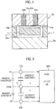
Z detection portion 30 is as shown inFIG. 3(b) . That is to say, four corners of the thirdmovable electrode 31 and the sidewall portions of therectangular frame 30a are coupled to each other by the two pairs of L-like beam portions movable electrode 31 is made movable in parallel in the vertical direction. A shape of thebeam portions beam portions beam portions upper fixing plate 2a, which is opposite to the thirdmovable electrode 31, the thirdfixed electrode 33a is provided, and on the side of thelower fixing plate 2b, which is opposite to the thirdmovable electrode 31, the fixedelectrode 33b is provided. The thirdfixed electrode 33a is pulled out to the upper surface of theupper fixing plate 2a by using athird penetration electrode 34a. The thirdfixed electrode 33b includes a protruding region 33b2 that protrudes from a rectangular region 33b1 (refer toFIG. 2 ). Such a configuration is made, in which the protruding region 33b2 is connected to a pillar-likefixed electrode 34c separated from the thirdmovable electrode 31, and the pillar-likefixed electrode 34c is connected to athird penetration electrode 34b provided in theupper fixing plate 2a. In such a way, the thirdfixed electrode 33b can be pulled out to the upper surface of theupper fixing plate 2a by using the pillar-likefixed electrode 34c and thethird penetration electrode 34b. A material of thethird penetration electrodes third penetration electrodes - An electrostatic capacitance C can be calculated by C = εS/d, where ε is a dielectric constant, S is an opposite area of an electrode, and d is an opposite gap. When the movable electrode rotates by the acceleration, the opposite gap d is changed, and accordingly, the electrostatic capacitance C is changed. Accordingly, differential capacitances (C1-C2, C5-C6) are subjected to CV conversion by the
ASIC 200. -
FIG. 4 shows a cross section of theX detection portion 10 in a state where the acceleration in the X direction is not applied. In this case, as shown inFIG. 5 , electrostatic capacitances C1 and C2 between the firstmovable electrode 11 and the firstfixed electrodes ASIC 200 calculates a differential value (C1-C2 = 0) between the electrostatic capacitance C1 and the electrostatic capacitance C2, and outputs the calculated differential value as an X output. -
FIG. 6 shows a cross section of theX detection portion 10 in a state where an acceleration of 1G is applied in the X direction. In this case, as shown inFIG. 7 , the electrostatic capacitance C1 between the firstmovable electrode 11 and the firstfixed electrode 13a becomes a parasitic capacitance +ΔC, and the electrostatic capacitance C2 between the firstmovable electrode 11 and the firstfixed electrode 13b becomes a parasitic capacitance -ΔC. TheASIC 200 calculates a differential value (C1-C2 = 2ΔC) between the electrostatic capacitance C1 and the electrostatic capacitance C2, and outputs the calculated differential value as an X output. - As described above, the
X detection portion 10 detects the acceleration in the X direction based on the changes of the electrostatic capacitances. A principle according to which theY detection portion 20 detects the acceleration in the Y direction is also similar to the above. -
FIG. 8 shows a cross section of theZ detection portion 30 in a state where the acceleration of 1 G is applied in the Z direction. In this case, as shown inFIG. 9 , an electrostatic capacitance C5 between the thirdmovable electrode 31 and the thirdfixed electrode 33a becomes the parasitic capacitance +ΔC, and an electrostatic capacitance C6 between the thirdmovable electrode 31 and the thirdfixed electrode 33b becomes the parasitic capacitance -ΔC. TheASIC 200 calculates a differential value (C5-C6 = 2ΔC) between the electrostatic capacitance C5 and the electrostatic capacitance C6, and outputs the calculated differential value as a Z output. As described above, theZ detection portion 30 detects the acceleration in the Z direction based on the changes of the electrostatic capacitances. - As described above, in the acceleration sensor according to this embodiment, the
X detection portion 10, theY detection portion 20 and theZ detection portion 30 are arranged in one chip, and accordingly, detection sensitivity to the accelerations in the three directions perpendicular to one another can be enhanced. That is to say, torsion and parallel movement weights are employed, and accordingly, in comparison with the comb teeth-like sensor as described in documentWO 2010/032818 A1 , heavier weights can be fabricated in the same planar size, 1hus making it possible to obtain high detection sensitivity. - Moreover, in the acceleration sensor according to this embodiment, the respective weights for detecting the accelerations in the XYZ three-axis directions are formed as the individual weights for the respective axes, each of which detects only the single-axis acceleration. Then, the acceleration in the planar directions (XY directions) is detected by operating the weight like a seesaw about the pair of twist beams, and the acceleration in the vertical direction (Z direction) is detected by moving the weight, which is held by the one or more pairs of beams, in parallel in the vertical direction. In three-axis detection by a plurality of the chips, a total size of all of the chips is increased, and moreover, it is necessary to package the plurality of chips. On the other hand, if the respective sensors for the three-axis directions are arranged in one chip, then such peripheral regions of the respective sensors can be shared with one another, and accordingly, it is possible to achieve miniaturization of a chip size and reduction of the number of chips to be packaged.
- Moreover, in the acceleration sensor according to this embodiment, the
X detection portion 10 arranges the firstfixed electrodes fixed electrodes movable electrode 11 with the straight line that connects the pair ofbeam portions movable electrode 11 and the firstfixed electrodes Y detection portion 20 arranges the secondfixed electrodes fixed electrodes movable electrode 21 with the straight line that connects the pair ofbeam portions movable electrode 21 and the secondfixed electrodes Z detection portion 30 arranges the thirdfixed electrodes fixed electrodes movable electrode 31. In such a way, the acceleration in the Z direction can be detected based on the changes of the electrostatic capacitance between the thirdmovable electrode 31 and the thirdfixed electrodes - According to such a configuration, the differential capacitance can be detected by two-electrode arrangement, and accordingly, it is possible to cancel the parasitic capacitance. That is to say, in a method that does not detect the differential capacitance, a peripheral parasitic capacitance is added besides the capacitance between the detection electrodes. Therefore, a noise influence of a parasitic capacitance portion occurs, and stability of the output with respect to the acceleration is deteriorated. On the other hand, in the method that detects the differential capacitance, the parasitic capacitance is canceled, and accordingly, the influence of the parasitic capacitance can be reduced. Moreover, it is possible to enhance linearlity by a difference calculation between an increment and decrement of a sensitivity capacitance.
- Moreover, in the acceleration sensor according to this embodiment, the third
fixed electrode 33b arranged on the back surface of the thirdmovable electrode 31 is pulled out to the upper surface (one side) of the thirdmovable electrode 31 through the pillar-likefixed electrode 34c separated from the thirdmovable electrode 31, thereby facilitating electrical connection thereof at the time of packaging the same. That is to say, in a case of pulling out the thirdfixed electrode 33b from the lower surface of the thirdmovable electrode 31, dual-sided packaging becomes necessary. On the other hand, if the thirdfixed electrode 33b is pulled out from the upper surface, then all of the electrodes can be pulled out from the upper surface of theupper fixing plate 2a, thereby facilitating the electrical connection at such packaging time. As a matter of course, there is also an advantage that the miniaturization of the acceleration sensor can be achieved. - Moreover, in the acceleration sensor according to this embodiment, the
X detection portion 10, theY detection portion 20 and theZ detection portion 30 are arranged in line. By such an arrangement as described above, the miniaturization of the acceleration sensor can be achieved. - Furthermore, in the acceleration sensor according to this embodiment, the
Z detection portion 30 is arranged in the center, and theX detection portion 10 and theY detection portion 20 are arranged on both sides thereof, and accordingly, a structure in which a stress state is stable can be fabricated. That is to say, while theX detection portion 10 and theY detection portion 20 have the same shape, theZ detection portion 30 has a different shape, and accordingly, the stress state becomes unstable depending on a way of arrangement. On the other hand, theX detection portion 10 and theY detection portion 20 are formed into the same shape, in which only the orientations are rotated by 90° with respect to each other, and by arraying them on both sides of theZ detection portion 30 having the different shape, then the structure in which the stress state is stable can be fabricated. - Incidentally, the
Z detection portion 30 is not formed into a symmetric structure, and accordingly, when the temperature is changed, an asymmetric stress is sometimes generated in a coupled portion thereof to theupper fixing plate 2a made of a different type of material. In such a case, thebeam portions -
FIG. 10 is an exploded perspective view of an acceleration sensor according to the second embodiment. As shown in this drawing, in theframe portion 3 among theZ detection portion 30, theX detection portion 10 and theY detection portion 20,joint regions beam portions Z detection portion 30 are made slightly lower than other regions. Therefore, even if theframe portion 3 is sandwiched between theupper fixing plate 2a and thelower fixing plate 2b, thejoint regions upper fixing plate 2a. A size of gaps between thejoint regions upper fixing plate 2a is not particularly limited; however, it is set at a size by which thejoint regions upper fixing plate 2a are not coupled to each other even if the temperature is changed. By such a configuration, thejoint regions upper fixing plate 2a are not coupled to each other, and accordingly, an influence of the stress is reduced, and it becomes possible to reduce the characteristic change due to the temperature. -
FIG. 11 is an exploded perspective view of another acceleration sensor according to the second embodiment. As shown in this drawing, in theframe portion 3 among theZ detection portion 30, theX detection portion 10 and theY detection portion 20,symmetric regions joint regions Z detection portion 30 taken as a reference, may be separated from theupper fixing plate 2a. A shape, area and height of thesymmetric region 35c are substantially the same as those of thejoint region 35a, and a shape, area and height of thesymmetric region 35d are substantially the same as those of thejoint region 35b. In such a way, theframe portion 3 on the periphery of theZ detection portion 30 is completely formed into the symmetric structure, and accordingly, an unbalance of the stress generated in a coupled portion thereof to theupper fixing plate 2a can be suppressed, which can further reduce the characteristic change due to the temperature. - As described above, in the acceleration sensor according to this embodiment, in a state where the
frame portion 3 is sandwiched by theupper fixing plate 2a and thelower fixing plate 2b, thejoint regions upper fixing plate 2a. In such a way, thejoint regions upper fixing plate 2a are not coupled to each other, and accordingly, the influence of the stress is reduced, and it becomes possible to reduce the characteristic change due to the temperature. Even if thejoint regions Z detection portion 30 is arranged in the center, and theX detection portion 10 and theY detection portion 20 are arranged on both sides thereof, and accordingly, air tightness in therectangular frame 30a can be ensured, to realize a configuration in which dust and the like are not mixed into therectangular frame 30a. - Moreover, in the acceleration sensor in this embodiment, the
symmetric regions joint regions Z detection portion 30 taken as a reference, are separated from theupper fixing plate 2a. In such a way, theframe portion 3 on the periphery of theZ detection portion 30 completely takes the symmetric structure, and accordingly, the unbalance of the stress generated in the coupled portion thereof to theupper fixing plate 2a can be suppressed, which can reduce the characteristic change due to the temperature. Even if suchsymmetric regions Z detection portion 30 is arranged in the center, and theX detection portion 10 and theY detection portion 20 are arranged on both sides thereof, and accordingly, the air tightness in therectangular frame 30a can be ensured, to realize the configuration in which the dust and the like are not mixed into therectangular frame 30a. - The description of the preferred embodiments of the present invention has been made above; however, the present invention is not limited to the above-described embodiments, and is modifiable in various ways. For example, in the above-described respective embodiments, the configuration is exemplified, in which the four corners of the third
movable electrode 31 and the sidewall portions of therectangular frame 30a are coupled to each other by the two pairs ofbeam portions movable electrode 31 and the sidewall portions of therectangular frame 30a may be coupled to each other by the one pair ofbeam portions upper fixing plate 2a, thelower fixing plate 2b, thesensor unit 1 and other details. - However, even in the second embodiment, when attention is paid to still another region of the periphery of the
Z detection portion 30, there is a spot which does not have a symmetric structure. That is to say, in the second embodiment, as shown inFIG. 11 , the structure is employed, in which the thirdfixed electrode 33b is pulled out to the upper surface of theupper fixing plate 2a by using the pillar-likefixed electrode 34c; however, the pillar-likefixed electrode 34c is formed only on the right side of theZ detection portion 30. Therefore, when the temperature is changed, an asymmetric stress is sometimes generated in the coupled portion thereof to theupper fixing plate 2a made of the different type of material. In such a case, thebeam portions Z detection portion 30 is changed, whereby the characteristic change due to the temperature is further reduced. Note that, in the following description, a detailed description of similar configurations to those of the second embodiment is omitted. - First,
FIG. 12 (a) is a top view of theZ detection portion 30 of the acceleration sensor according to the second embodiment. As already described, the four corners of the thirdmovable electrode 31 are coupled to theframe portion 3 by the two pairs of L-like beam portions portion 36a is formed only on the right side of the thirdmovable electrode 31, and the pillar-likefixed electrode 34c is pulled out through this throughportion 36a. Therefore, there is a possibility that the characteristic change due to the temperature may occur. -
FIG. 12 (b) is a top view of aZ detection portion 30 of an acceleration sensor according to Example 1. As shown in this drawing, in Example 1, throughportions movable electrode 31 taken as a reference, are formed on theframe portion 3 on both sides in a first direction of the thirdmovable electrode 31. For example, the first direction is an arrangement direction (crosswise direction) in the case where theZ detection portion 30 is located at the center, and theX detection portion 10, theY detection portion 20 and theZ detection portion 30 are arranged in line. That is to say, on both left and right sides of theZ detection portion 30, theX detection portion 10 and theY detection portion 20, which have the same shape in which only the orientations are rotated by 90° with respect to each other, are arranged. If such a frame shape of theZ detection portion 30 is also formed into a bilaterally symmetric structure, then the structure in which the stress state is stable is fabricated, which enables to reduce the temperature characteristics. -
FIG. 12(c) is a top view of aZ detection portion 30 of an acceleration sensor according to Example 2. As shown in this drawing, in Example 2, pillar-likefixed electrodes portions fixed electrodes fixed electrode 34c is connected to the thirdfixed electrode 33b (refer toFIG. 8 ),there are no particular limitations to whether or not the pillar-likefixed electrode 34d is connected to the thirdfixed electrode 33b. That is to say, coupled portions of the pillar-likefixed electrodes upper fixing plate 2a made of the different type of material just need to be symmetric to each other. If not only the throughportions fixed electrodes -
FIG. 12(d) is a top view of aZ detection portion 30 of an acceleration sensor according to Example 3. As shown in this drawing, in Example 3, throughportions movable electrode 31 taken as a reference, are also formed on theframe portion 3 on both sides in a second direction. For example, the second direction is a direction (up and down direction) perpendicular to the first direction. If the frame shape of theZ detection portion 30 is formed into a symmetric structure not only bilaterally but also vertically as described above, then a bilaterally and vertically symmetric weight peripheral structure is realized, and accordingly, a further stabilized structure in stress state is obtained, which enables to further reduce the temperature characteristics. -
FIG. 12 (e) is a top view of aZ detection portion 30 of an acceleration sensor according to Example 4. As shown in this drawing, in Example 4, the pillar-likefixed electrodes portions frame portion 3, the throughportions -
FIG. 12(f) is a top view of aZ detection portion 30 of an acceleration sensor according to Example 5. As shown in this drawing, in Example 5, the pillar-likefixed electrodes portions fixed electrodes portions fixed electrodes fixed electrode 33b, either. If the pillar structure is made to have a bilaterally and vertically symmetric structure in the bilaterally and vertically symmetric weight peripheral structure as described above, then the structure in which the stress state is further stabilized is obtained, which enables to further reduce the temperature characteristics. - As described above, in the acceleration sensor according to this embodiment, the
X detection portion 10, theY detection portion 20, theZ detection portion 30 and theframe portion 3 are arranged in one chip, and the throughportions movable electrode 31 taken as a reference, are formed on theframe portion 3 on both sides in the first direction (for example, both right and left sides) of the thirdmovable electrode 31. TheX detection portion 10 detects the acceleration in the X direction by swinging the firstmovable electrode 11 about the pair ofbeam portions Y detection portion 20 detects the acceleration in the Y direction by swinging the secondmovable electrode 21 about the pair ofbeam portions Z detection portion 30 detects the acceleration in the Z direction by moving the thirdmovable electrode 31, which is held by the two pairs ofbeam portions 32b frame portion 3 incorporates theX detection portion 10, theY detection portion 20 and theZ detection portion 30 therein. In such a way, the frame shape of theZ detection portion 30 is formed into the bilaterally symmetric structure, and accordingly, the structure stabilized in stress state is obtained, which enables to reduce the temperature characteristics. As a result, the acceleration sensor, which can enhance detection accuracy of the accelerations in the three directions perpendicular to one another, can be provided. - Moreover, in the acceleration sensor according to this embodiment, the pillar-like
fixed electrodes portions 36a and 36 formed on both sides in the first direction (for example, both right and left sides). If not only the throughportions fixed electrodes - Furthermore, in the acceleration sensor according to this embodiment, the through
portions movable electrode 31 taken as a reference, may also be formed on theframe portion 3 on both sides in a second direction perpendicular to the first direction (for example, both upper and lower sides). If the frame shape of theZ detection portion 30 is formed into the symmetric structure not only bilaterally but also vertically as described above, then the bilaterally and vertical symmetric weight peripheral structure is obtained, and accordingly, the further stabilized structure in stress state is obtained, which enables to further reduce the temperature characteristics. - Moreover, in the acceleration sensor according to this embodiment, the pillar-like
fixed electrodes portions - Moreover, in the acceleration sensor according to this embodiment, the
X detection portion 10, theY detection portion 20 and theZ detection portion 30 may be arranged in line with theZ detection portion 30 located at the center, and such a linear arrangement direction may be the first direction (for example, the right and left direction). In such a way, the throughportions X detection portion 10 and theZ detection portion 30 and in the region between theZ detection portion 30 and theY detection portion 20, and accordingly, it becomes possible to achieve miniaturization of the acceleration sensor. - The description of the preferred embodiments of the present invention has been made above; however, the present invention is not limited to the above-described embodiments, and is modifiable in various ways. For example,
FIG. 11 shows a state where thejoint regions symmetric regions upper fixing plate 2a; however, it does not matter whether these regions are coupled. Moreover, inFIG. 12(f) , the pillar-likefixed electrodes portions fixed electrodes portions portions fixed electrodes - The entire contents of Japanese Patent Application No.
2012-226509 (filed on: October 12, 2012 2013-119688 (filed on: June 6, 2013 - The acceleration sensor according to the present invention is applicable to the acceleration sensor which needs to enhance the detection sensitivity for the accelerations in the three directions perpendicular to one another.
-
- 2a
- UPPER FIXING PLATE (FIRST FIXING PLATE)
- 2b
- LOWER FIXING PLATE (SECOND FIXING PLATE)
- 3
- FRAME PORTION
- 10
- X DETECTION PORTION
- 11
- FIRST MOVABLE ELECTRODE
- 12a, 12b
- PAIR OF BEAM PORTIONS
- 13a, 13b
- FIRST FIXED ELECTRODE
- 20
- Y DETECTION PORTION
- 21
- SECOND MOVABLE ELECTRODE
- 22a, 22b
- PAIR OF BEAM PORTIONS
- 23a, 23b
- SECOND FIXED ELECTRODE
- 30
- Z DETECTION PORTION
- 31
- THIRD MOVABLE ELECTRODE
- 32a, 32b, 32c, 32d
- PAIR OR MORE OF BEAM PORTIONS
- 33a, 33b
- THIRD FIXED ELECTRODE
- 34c, 34d, 34e, 34f
- PILLAR-LIKE FIXED ELECTRODE
- 35a, 35b
- JOINT REGION
- 35c, 35d
- SYMMETRIC REGION
- 36a, 36b, 36c, 36d
- THROUGH PORTIONS
Claims (2)
- An acceleration sensor comprising:an X detection portion (10) that detects acceleration in an X direction as one direction in planer directions by swinging a first movable electrode (11) about a pair of beam portions (12a, 12b);a Y detection portion (20) that detects acceleration in a Y direction perpendicular to the X direction, the Y direction being one direction in the planer directions, by swinging a second movable electrode (21) about a pair of beam portions (22a, 22b); anda Z detection portion (30) that detects acceleration in a Z direction as a vertical direction by moving a third movable electrode (31) in parallel in the vertical direction, the third movable electrode (31) being held by a pair or more of beam portions (32a, 32b, 32c, 32d),wherein the X detection portion (10), the Y detection portion (20) and the Z detection portion (30) are arranged in one chip,wherein the X detection portion (10) arranges first fixed electrodes (13a, 13b) so that the first fixed electrodes (13a, 13b) can be opposed to one side and the other side of a front surface of the first movable electrode (11) with a straight line that connects the pair of beam portions to each other as a borderline, and detects the acceleration in the X direction based on changes of electrostatic capacitances between the first movable electrode (11) and the first fixed electrodes (13a, 13b),the Y detection portion (20) arranges second fixed electrodes (23a, 23b) so that the second fixed electrodes (23a, 23b) can be opposed to one side and the other side of a front surface of the second movable electrode (21) with a straight line that connects the pair of beam portions (22a, 22b) to each other as a borderline, and detects the acceleration in the Y direction based on changes of electrostatic capacitances between the second movable electrode (21) and the second fixed electrodes (23a, 23b),wherein the acceleration sensor is characterized in thatthe Z detection portion (30) arranges third fixed electrodes (33a, 33b) so that the third fixed electrodes (33a, 33b) can be opposed to a front surface and a back surface of the third movable electrode (31), and detects the acceleration in the Z direction based on changes of electrostatic capacitances between the third movable electrode (31) and the third fixed electrodes (33a, 33b),wherein the X-detection portion (10), the Y-detection portion (20) and the Z detection portion (30) are arranged in line.wherein the Z detection portion (30) is arranged in the center, and the X detection portion (10) and the Y detection portion (20) are arranged on both sides of the Z detection portion (30),wherein, in a state where a frame portion (3), that incorporates the X detection portion (10), the Y detection portion (20) and the Z detection portion (30) therein, is sandwiched by a first fixing plate (2a) and a second fixing plate (2b), joint regions (35a, 35b) of the beam portions (32a, 32b, 32c, 32d) of the Z detection portion (30) in the frame portion (3) between the Z detection portion (30) and the X detection portion (10) and between the Z detection portion (30) and the Y detection portion (20) are separated from the first fixing plate (2a),wherein, in the frame portion (3) between the Z detection portion (30) and the X detection portion (10) and between the Z detection portion (30) and the Y detection portion (20), symmetric regions (35c, 35d) which are symmetric to the joint regions (35a, 35b) with respect to the Z detection portion (30) taken as a reference are separated from the first fixing plate (2a).
- The acceleration sensor according to either one of claims 1, wherein the third fixed electrode (33a, 33b) arranged on the back surface of the third movable electrode (31) is pulled out to one side of the third movable electrode (31) through a pillar-like fixed electrode (34c) separated from the third movable electrode (31).
Applications Claiming Priority (3)
| Application Number | Priority Date | Filing Date | Title |
|---|---|---|---|
| JP2012226509A JP6032407B2 (en) | 2012-10-12 | 2012-10-12 | Acceleration sensor |
| JP2013119688A JP6074854B2 (en) | 2013-06-06 | 2013-06-06 | Acceleration sensor |
| PCT/JP2013/005759 WO2014057623A1 (en) | 2012-10-12 | 2013-09-27 | Acceleration sensor |
Publications (3)
| Publication Number | Publication Date |
|---|---|
| EP2908141A1 EP2908141A1 (en) | 2015-08-19 |
| EP2908141A4 EP2908141A4 (en) | 2015-08-19 |
| EP2908141B1 true EP2908141B1 (en) | 2017-03-15 |
Family
ID=50477107
Family Applications (1)
| Application Number | Title | Priority Date | Filing Date |
|---|---|---|---|
| EP13845916.9A Active EP2908141B1 (en) | 2012-10-12 | 2013-09-27 | Acceleration sensor |
Country Status (3)
| Country | Link |
|---|---|
| US (1) | US20150260752A1 (en) |
| EP (1) | EP2908141B1 (en) |
| WO (1) | WO2014057623A1 (en) |
Families Citing this family (3)
| Publication number | Priority date | Publication date | Assignee | Title |
|---|---|---|---|---|
| ITTO20130237A1 (en) * | 2013-03-22 | 2014-09-23 | St Microelectronics Srl | HIGH SENSITIVITY MICROELECTROMECHANICAL DETECTION OF Z AXIS, IN PARTICULAR FOR A MEMS ACCELEROMETER |
| JP6704126B2 (en) | 2015-12-17 | 2020-06-03 | パナソニックIpマネジメント株式会社 | Connection structure |
| US11761977B1 (en) * | 2022-04-29 | 2023-09-19 | Invensense, Inc. | MEMS design with shear force rejection for reduced offset |
Family Cites Families (13)
| Publication number | Priority date | Publication date | Assignee | Title |
|---|---|---|---|---|
| US4969359A (en) * | 1989-04-06 | 1990-11-13 | Ford Motor Company | Silicon accelerometer responsive to three orthogonal force components and method for fabricating |
| DE69206770T2 (en) * | 1991-12-19 | 1996-07-11 | Motorola Inc | Triaxial accelerometer |
| JPH09113534A (en) * | 1995-10-23 | 1997-05-02 | Yoshinobu Matsumoto | Accelerometer |
| JPH1151967A (en) * | 1997-08-08 | 1999-02-26 | Mitsubishi Electric Corp | Multi-axis acceleration sensor and manufacturing method thereof |
| JP3307328B2 (en) * | 1998-05-11 | 2002-07-24 | 株式会社デンソー | Semiconductor dynamic quantity sensor |
| US6829937B2 (en) * | 2002-06-17 | 2004-12-14 | Vti Holding Oy | Monolithic silicon acceleration sensor |
| JP2004361115A (en) * | 2003-06-02 | 2004-12-24 | Denso Corp | Semiconductor dynamic quantity sensor |
| EP2284545B1 (en) * | 2004-01-07 | 2018-08-08 | Northrop Grumman Corporation | Coplanar proofmasses employable to sense acceleration along three axes |
| EP2023152A4 (en) * | 2006-04-28 | 2011-11-02 | Panasonic Elec Works Co Ltd | CAPACITOR SENSOR |
| WO2009090841A1 (en) * | 2008-01-15 | 2009-07-23 | Alps Electric Co., Ltd. | Electrostatic capacity type acceleration sensor |
| JP2010066231A (en) * | 2008-09-12 | 2010-03-25 | Mitsubishi Electric Corp | Acceleration sensor |
| JP5357166B2 (en) | 2008-09-22 | 2013-12-04 | アルプス電気株式会社 | MEMS sensor and detection apparatus |
| US8138007B2 (en) * | 2009-08-26 | 2012-03-20 | Freescale Semiconductor, Inc. | MEMS device with stress isolation and method of fabrication |
-
2013
- 2013-09-27 EP EP13845916.9A patent/EP2908141B1/en active Active
- 2013-09-27 US US14/432,477 patent/US20150260752A1/en not_active Abandoned
- 2013-09-27 WO PCT/JP2013/005759 patent/WO2014057623A1/en not_active Ceased
Non-Patent Citations (1)
| Title |
|---|
| None * |
Also Published As
| Publication number | Publication date |
|---|---|
| US20150260752A1 (en) | 2015-09-17 |
| EP2908141A1 (en) | 2015-08-19 |
| WO2014057623A1 (en) | 2014-04-17 |
| EP2908141A4 (en) | 2015-08-19 |
Similar Documents
| Publication | Publication Date | Title |
|---|---|---|
| US7617729B2 (en) | Accelerometer | |
| US8333113B2 (en) | Triaxial acceleration sensor | |
| EP3156804B1 (en) | Microelectromechanical sensor device with reduced stress sensitivity | |
| EP3882641A1 (en) | Mems accelerometer with mechanically decoupled proof mass | |
| US8272268B2 (en) | Triaxial acceleration sensor | |
| US9097736B2 (en) | Micromechanical component and method for manufacturing a micromechanical component | |
| US11255873B2 (en) | Increased sensitivity z-axis accelerometer | |
| CN106597016A (en) | Capacitive MEMS dual-axis accelerometer | |
| WO2009063473A2 (en) | Accelerometer | |
| US20070034007A1 (en) | Multi-axis micromachined accelerometer | |
| EP2693183A1 (en) | On-chip resonant acceleration and pressure sensor | |
| US20160370403A1 (en) | Capacitive accelerometer devices and wafer level vacuum encapsulation methods | |
| US9128114B2 (en) | Capacitive sensor device and a method of sensing accelerations | |
| CN206321662U (en) | A kind of MEMS twin-axis accelerometers | |
| EP4187258A1 (en) | Z-axis microelectromechanical sensor device with improved stress insensitivity | |
| EP3951403A1 (en) | Microelectromechanical sensor device with improved stability to stress | |
| US9739797B2 (en) | Sensor device | |
| EP2910953A1 (en) | Parallel plate capacitor and acceleration sensor comprising same | |
| TW201625953A (en) | A MEMS sensor and a semiconductor package | |
| JP6330055B2 (en) | Acceleration sensor | |
| EP2908141A1 (en) | Acceleration sensor | |
| JP6074854B2 (en) | Acceleration sensor | |
| JP6032407B2 (en) | Acceleration sensor | |
| JP2014077741A (en) | Acceleration sensor | |
| JP2015017819A (en) | Acceleration sensor |
Legal Events
| Date | Code | Title | Description |
|---|---|---|---|
| PUAI | Public reference made under article 153(3) epc to a published international application that has entered the european phase |
Free format text: ORIGINAL CODE: 0009012 |
|
| 17P | Request for examination filed |
Effective date: 20150331 |
|
| A4 | Supplementary search report drawn up and despatched |
Effective date: 20150721 |
|
| AK | Designated contracting states |
Kind code of ref document: A1 Designated state(s): AL AT BE BG CH CY CZ DE DK EE ES FI FR GB GR HR HU IE IS IT LI LT LU LV MC MK MT NL NO PL PT RO RS SE SI SK SM TR |
|
| AX | Request for extension of the european patent |
Extension state: BA ME |
|
| DAX | Request for extension of the european patent (deleted) | ||
| 17Q | First examination report despatched |
Effective date: 20160226 |
|
| GRAP | Despatch of communication of intention to grant a patent |
Free format text: ORIGINAL CODE: EPIDOSNIGR1 |
|
| INTG | Intention to grant announced |
Effective date: 20161116 |
|
| RIN1 | Information on inventor provided before grant (corrected) |
Inventor name: MORI, TAKESHI Inventor name: IBARA, NOBUYUKI Inventor name: TAURA, TAKUMI Inventor name: KISHIMOTO, SHINICHI Inventor name: YOSHIDA, HITOSHI Inventor name: UEDA, HIDEKI Inventor name: GODA, KAZUO |
|
| GRAS | Grant fee paid |
Free format text: ORIGINAL CODE: EPIDOSNIGR3 |
|
| GRAA | (expected) grant |
Free format text: ORIGINAL CODE: 0009210 |
|
| AK | Designated contracting states |
Kind code of ref document: B1 Designated state(s): AL AT BE BG CH CY CZ DE DK EE ES FI FR GB GR HR HU IE IS IT LI LT LU LV MC MK MT NL NO PL PT RO RS SE SI SK SM TR |
|
| REG | Reference to a national code |
Ref country code: CH Ref legal event code: EP Ref country code: GB Ref legal event code: FG4D |
|
| REG | Reference to a national code |
Ref country code: IE Ref legal event code: FG4D |
|
| REG | Reference to a national code |
Ref country code: AT Ref legal event code: REF Ref document number: 876127 Country of ref document: AT Kind code of ref document: T Effective date: 20170415 |
|
| REG | Reference to a national code |
Ref country code: DE Ref legal event code: R096 Ref document number: 602013018735 Country of ref document: DE |
|
| REG | Reference to a national code |
Ref country code: NL Ref legal event code: MP Effective date: 20170315 |
|
| REG | Reference to a national code |
Ref country code: LT Ref legal event code: MG4D |
|
| PG25 | Lapsed in a contracting state [announced via postgrant information from national office to epo] |
Ref country code: GR Free format text: LAPSE BECAUSE OF FAILURE TO SUBMIT A TRANSLATION OF THE DESCRIPTION OR TO PAY THE FEE WITHIN THE PRESCRIBED TIME-LIMIT Effective date: 20170616 Ref country code: FI Free format text: LAPSE BECAUSE OF FAILURE TO SUBMIT A TRANSLATION OF THE DESCRIPTION OR TO PAY THE FEE WITHIN THE PRESCRIBED TIME-LIMIT Effective date: 20170315 Ref country code: LT Free format text: LAPSE BECAUSE OF FAILURE TO SUBMIT A TRANSLATION OF THE DESCRIPTION OR TO PAY THE FEE WITHIN THE PRESCRIBED TIME-LIMIT Effective date: 20170315 Ref country code: HR Free format text: LAPSE BECAUSE OF FAILURE TO SUBMIT A TRANSLATION OF THE DESCRIPTION OR TO PAY THE FEE WITHIN THE PRESCRIBED TIME-LIMIT Effective date: 20170315 Ref country code: NO Free format text: LAPSE BECAUSE OF FAILURE TO SUBMIT A TRANSLATION OF THE DESCRIPTION OR TO PAY THE FEE WITHIN THE PRESCRIBED TIME-LIMIT Effective date: 20170615 |
|
| REG | Reference to a national code |
Ref country code: AT Ref legal event code: MK05 Ref document number: 876127 Country of ref document: AT Kind code of ref document: T Effective date: 20170315 |
|
| PG25 | Lapsed in a contracting state [announced via postgrant information from national office to epo] |
Ref country code: SE Free format text: LAPSE BECAUSE OF FAILURE TO SUBMIT A TRANSLATION OF THE DESCRIPTION OR TO PAY THE FEE WITHIN THE PRESCRIBED TIME-LIMIT Effective date: 20170315 Ref country code: BG Free format text: LAPSE BECAUSE OF FAILURE TO SUBMIT A TRANSLATION OF THE DESCRIPTION OR TO PAY THE FEE WITHIN THE PRESCRIBED TIME-LIMIT Effective date: 20170615 Ref country code: RS Free format text: LAPSE BECAUSE OF FAILURE TO SUBMIT A TRANSLATION OF THE DESCRIPTION OR TO PAY THE FEE WITHIN THE PRESCRIBED TIME-LIMIT Effective date: 20170315 Ref country code: LV Free format text: LAPSE BECAUSE OF FAILURE TO SUBMIT A TRANSLATION OF THE DESCRIPTION OR TO PAY THE FEE WITHIN THE PRESCRIBED TIME-LIMIT Effective date: 20170315 |
|
| PG25 | Lapsed in a contracting state [announced via postgrant information from national office to epo] |
Ref country code: NL Free format text: LAPSE BECAUSE OF FAILURE TO SUBMIT A TRANSLATION OF THE DESCRIPTION OR TO PAY THE FEE WITHIN THE PRESCRIBED TIME-LIMIT Effective date: 20170315 |
|
| PG25 | Lapsed in a contracting state [announced via postgrant information from national office to epo] |
Ref country code: ES Free format text: LAPSE BECAUSE OF FAILURE TO SUBMIT A TRANSLATION OF THE DESCRIPTION OR TO PAY THE FEE WITHIN THE PRESCRIBED TIME-LIMIT Effective date: 20170315 Ref country code: CZ Free format text: LAPSE BECAUSE OF FAILURE TO SUBMIT A TRANSLATION OF THE DESCRIPTION OR TO PAY THE FEE WITHIN THE PRESCRIBED TIME-LIMIT Effective date: 20170315 Ref country code: SK Free format text: LAPSE BECAUSE OF FAILURE TO SUBMIT A TRANSLATION OF THE DESCRIPTION OR TO PAY THE FEE WITHIN THE PRESCRIBED TIME-LIMIT Effective date: 20170315 Ref country code: RO Free format text: LAPSE BECAUSE OF FAILURE TO SUBMIT A TRANSLATION OF THE DESCRIPTION OR TO PAY THE FEE WITHIN THE PRESCRIBED TIME-LIMIT Effective date: 20170315 Ref country code: IT Free format text: LAPSE BECAUSE OF FAILURE TO SUBMIT A TRANSLATION OF THE DESCRIPTION OR TO PAY THE FEE WITHIN THE PRESCRIBED TIME-LIMIT Effective date: 20170315 Ref country code: AT Free format text: LAPSE BECAUSE OF FAILURE TO SUBMIT A TRANSLATION OF THE DESCRIPTION OR TO PAY THE FEE WITHIN THE PRESCRIBED TIME-LIMIT Effective date: 20170315 Ref country code: EE Free format text: LAPSE BECAUSE OF FAILURE TO SUBMIT A TRANSLATION OF THE DESCRIPTION OR TO PAY THE FEE WITHIN THE PRESCRIBED TIME-LIMIT Effective date: 20170315 |
|
| PG25 | Lapsed in a contracting state [announced via postgrant information from national office to epo] |
Ref country code: PT Free format text: LAPSE BECAUSE OF FAILURE TO SUBMIT A TRANSLATION OF THE DESCRIPTION OR TO PAY THE FEE WITHIN THE PRESCRIBED TIME-LIMIT Effective date: 20170717 Ref country code: PL Free format text: LAPSE BECAUSE OF FAILURE TO SUBMIT A TRANSLATION OF THE DESCRIPTION OR TO PAY THE FEE WITHIN THE PRESCRIBED TIME-LIMIT Effective date: 20170315 Ref country code: IS Free format text: LAPSE BECAUSE OF FAILURE TO SUBMIT A TRANSLATION OF THE DESCRIPTION OR TO PAY THE FEE WITHIN THE PRESCRIBED TIME-LIMIT Effective date: 20170715 Ref country code: SM Free format text: LAPSE BECAUSE OF FAILURE TO SUBMIT A TRANSLATION OF THE DESCRIPTION OR TO PAY THE FEE WITHIN THE PRESCRIBED TIME-LIMIT Effective date: 20170315 |
|
| REG | Reference to a national code |
Ref country code: DE Ref legal event code: R097 Ref document number: 602013018735 Country of ref document: DE |
|
| PLBE | No opposition filed within time limit |
Free format text: ORIGINAL CODE: 0009261 |
|
| STAA | Information on the status of an ep patent application or granted ep patent |
Free format text: STATUS: NO OPPOSITION FILED WITHIN TIME LIMIT |
|
| PG25 | Lapsed in a contracting state [announced via postgrant information from national office to epo] |
Ref country code: DK Free format text: LAPSE BECAUSE OF FAILURE TO SUBMIT A TRANSLATION OF THE DESCRIPTION OR TO PAY THE FEE WITHIN THE PRESCRIBED TIME-LIMIT Effective date: 20170315 |
|
| 26N | No opposition filed |
Effective date: 20171218 |
|
| PG25 | Lapsed in a contracting state [announced via postgrant information from national office to epo] |
Ref country code: SI Free format text: LAPSE BECAUSE OF FAILURE TO SUBMIT A TRANSLATION OF THE DESCRIPTION OR TO PAY THE FEE WITHIN THE PRESCRIBED TIME-LIMIT Effective date: 20170315 |
|
| REG | Reference to a national code |
Ref country code: CH Ref legal event code: PL |
|
| GBPC | Gb: european patent ceased through non-payment of renewal fee |
Effective date: 20170927 |
|
| PG25 | Lapsed in a contracting state [announced via postgrant information from national office to epo] |
Ref country code: MC Free format text: LAPSE BECAUSE OF FAILURE TO SUBMIT A TRANSLATION OF THE DESCRIPTION OR TO PAY THE FEE WITHIN THE PRESCRIBED TIME-LIMIT Effective date: 20170315 |
|
| REG | Reference to a national code |
Ref country code: IE Ref legal event code: MM4A |
|
| REG | Reference to a national code |
Ref country code: BE Ref legal event code: MM Effective date: 20170930 |
|
| PG25 | Lapsed in a contracting state [announced via postgrant information from national office to epo] |
Ref country code: LU Free format text: LAPSE BECAUSE OF NON-PAYMENT OF DUE FEES Effective date: 20170927 |
|
| REG | Reference to a national code |
Ref country code: FR Ref legal event code: ST Effective date: 20180531 |
|
| PG25 | Lapsed in a contracting state [announced via postgrant information from national office to epo] |
Ref country code: GB Free format text: LAPSE BECAUSE OF NON-PAYMENT OF DUE FEES Effective date: 20170927 Ref country code: LI Free format text: LAPSE BECAUSE OF NON-PAYMENT OF DUE FEES Effective date: 20170930 Ref country code: IE Free format text: LAPSE BECAUSE OF NON-PAYMENT OF DUE FEES Effective date: 20170927 Ref country code: CH Free format text: LAPSE BECAUSE OF NON-PAYMENT OF DUE FEES Effective date: 20170930 |
|
| PG25 | Lapsed in a contracting state [announced via postgrant information from national office to epo] |
Ref country code: BE Free format text: LAPSE BECAUSE OF NON-PAYMENT OF DUE FEES Effective date: 20170930 Ref country code: FR Free format text: LAPSE BECAUSE OF NON-PAYMENT OF DUE FEES Effective date: 20171002 |
|
| PG25 | Lapsed in a contracting state [announced via postgrant information from national office to epo] |
Ref country code: MT Free format text: LAPSE BECAUSE OF NON-PAYMENT OF DUE FEES Effective date: 20170927 |
|
| PG25 | Lapsed in a contracting state [announced via postgrant information from national office to epo] |
Ref country code: HU Free format text: LAPSE BECAUSE OF FAILURE TO SUBMIT A TRANSLATION OF THE DESCRIPTION OR TO PAY THE FEE WITHIN THE PRESCRIBED TIME-LIMIT; INVALID AB INITIO Effective date: 20130927 |
|
| PG25 | Lapsed in a contracting state [announced via postgrant information from national office to epo] |
Ref country code: CY Free format text: LAPSE BECAUSE OF FAILURE TO SUBMIT A TRANSLATION OF THE DESCRIPTION OR TO PAY THE FEE WITHIN THE PRESCRIBED TIME-LIMIT Effective date: 20170315 |
|
| PG25 | Lapsed in a contracting state [announced via postgrant information from national office to epo] |
Ref country code: MK Free format text: LAPSE BECAUSE OF FAILURE TO SUBMIT A TRANSLATION OF THE DESCRIPTION OR TO PAY THE FEE WITHIN THE PRESCRIBED TIME-LIMIT Effective date: 20170315 |
|
| PG25 | Lapsed in a contracting state [announced via postgrant information from national office to epo] |
Ref country code: TR Free format text: LAPSE BECAUSE OF FAILURE TO SUBMIT A TRANSLATION OF THE DESCRIPTION OR TO PAY THE FEE WITHIN THE PRESCRIBED TIME-LIMIT Effective date: 20170315 |
|
| PG25 | Lapsed in a contracting state [announced via postgrant information from national office to epo] |
Ref country code: AL Free format text: LAPSE BECAUSE OF FAILURE TO SUBMIT A TRANSLATION OF THE DESCRIPTION OR TO PAY THE FEE WITHIN THE PRESCRIBED TIME-LIMIT Effective date: 20170315 |
|
| PGFP | Annual fee paid to national office [announced via postgrant information from national office to epo] |
Ref country code: DE Payment date: 20240918 Year of fee payment: 12 |