EP2908104A1 - Thermal type flowmeter and method for determined abnormality thereof - Google Patents
Thermal type flowmeter and method for determined abnormality thereof Download PDFInfo
- Publication number
- EP2908104A1 EP2908104A1 EP13844854.3A EP13844854A EP2908104A1 EP 2908104 A1 EP2908104 A1 EP 2908104A1 EP 13844854 A EP13844854 A EP 13844854A EP 2908104 A1 EP2908104 A1 EP 2908104A1
- Authority
- EP
- European Patent Office
- Prior art keywords
- thermo
- output signal
- output
- relationship
- sensitive element
- Prior art date
- Legal status (The legal status is an assumption and is not a legal conclusion. Google has not performed a legal analysis and makes no representation as to the accuracy of the status listed.)
- Granted
Links
Images




Classifications
-
- G—PHYSICS
- G01—MEASURING; TESTING
- G01F—MEASURING VOLUME, VOLUME FLOW, MASS FLOW OR LIQUID LEVEL; METERING BY VOLUME
- G01F1/00—Measuring the volume flow or mass flow of fluid or fluent solid material wherein the fluid passes through a meter in a continuous flow
- G01F1/68—Measuring the volume flow or mass flow of fluid or fluent solid material wherein the fluid passes through a meter in a continuous flow by using thermal effects
- G01F1/696—Circuits therefor, e.g. constant-current flow meters
-
- G—PHYSICS
- G01—MEASURING; TESTING
- G01F—MEASURING VOLUME, VOLUME FLOW, MASS FLOW OR LIQUID LEVEL; METERING BY VOLUME
- G01F1/00—Measuring the volume flow or mass flow of fluid or fluent solid material wherein the fluid passes through a meter in a continuous flow
- G01F1/68—Measuring the volume flow or mass flow of fluid or fluent solid material wherein the fluid passes through a meter in a continuous flow by using thermal effects
- G01F1/684—Structural arrangements; Mounting of elements, e.g. in relation to fluid flow
- G01F1/6845—Micromachined devices
-
- G—PHYSICS
- G01—MEASURING; TESTING
- G01F—MEASURING VOLUME, VOLUME FLOW, MASS FLOW OR LIQUID LEVEL; METERING BY VOLUME
- G01F15/00—Details of, or accessories for, apparatus of groups G01F1/00 - G01F13/00 insofar as such details or appliances are not adapted to particular types of such apparatus
- G01F15/02—Compensating or correcting for variations in pressure, density or temperature
- G01F15/04—Compensating or correcting for variations in pressure, density or temperature of gases to be measured
- G01F15/043—Compensating or correcting for variations in pressure, density or temperature of gases to be measured using electrical means
- G01F15/046—Compensating or correcting for variations in pressure, density or temperature of gases to be measured using electrical means involving digital counting
-
- G—PHYSICS
- G01—MEASURING; TESTING
- G01P—MEASURING LINEAR OR ANGULAR SPEED, ACCELERATION, DECELERATION, OR SHOCK; INDICATING PRESENCE, ABSENCE, OR DIRECTION, OF MOVEMENT
- G01P21/00—Testing or calibrating of apparatus or devices covered by the preceding groups
-
- G—PHYSICS
- G01—MEASURING; TESTING
- G01P—MEASURING LINEAR OR ANGULAR SPEED, ACCELERATION, DECELERATION, OR SHOCK; INDICATING PRESENCE, ABSENCE, OR DIRECTION, OF MOVEMENT
- G01P5/00—Measuring speed of fluids, e.g. of air stream; Measuring speed of bodies relative to fluids, e.g. of ship, of aircraft
- G01P5/10—Measuring speed of fluids, e.g. of air stream; Measuring speed of bodies relative to fluids, e.g. of ship, of aircraft by measuring thermal variables
-
- G—PHYSICS
- G01—MEASURING; TESTING
- G01P—MEASURING LINEAR OR ANGULAR SPEED, ACCELERATION, DECELERATION, OR SHOCK; INDICATING PRESENCE, ABSENCE, OR DIRECTION, OF MOVEMENT
- G01P5/00—Measuring speed of fluids, e.g. of air stream; Measuring speed of bodies relative to fluids, e.g. of ship, of aircraft
- G01P5/10—Measuring speed of fluids, e.g. of air stream; Measuring speed of bodies relative to fluids, e.g. of ship, of aircraft by measuring thermal variables
- G01P5/12—Measuring speed of fluids, e.g. of air stream; Measuring speed of bodies relative to fluids, e.g. of ship, of aircraft by measuring thermal variables using variation of resistance of a heated conductor
Definitions
- the present invention relates to a thermal type flowmeter and a method for determining an abnormality thereof.
- the sensor chip includes a semiconductor substrate constructed with a silicon substrate, a heater, and a pair of thermo-sensitive elements.
- One of the pair of thermo-sensitive elements is arranged on an upstream side of the flow passage with respect to the heater.
- the other thermo-sensitive element is arranged on a downstream side of the flow passage with respect to the heater.
- thermo-sensitive element When the fluid such as gas flows in the flow passage, heat generated by the heater is transmitted to the downstream-side thermo-sensitive element. Accordingly, a difference is generated between a voltage output from the upstream-side thermo-sensitive element and a voltage output from the downstream-side thermo-sensitive element. The flow rate of the fluid is calculated based on the difference voltage.
- Patent Document 1 discloses the following failure determination method.
- a resistance value of the upstream-side thermopile is calculated from the voltage at the upstream-side thermopile.
- a resistance value of the downstream-side thermopile is calculated from the voltage at the downstream-side thermopile.
- a failure of a flow sensor is determined when one of the resistance values is abnormal.
- Patent Document 1 Japanese Unexamined Patent Publication No. 2000-321107
- Japanese Unexamined Patent Publication No. 2000-321107 proposes the method in which the resistance value of the thermopile is calculated as the method for detecting the failure of the flow sensor.
- Japanese Unexamined Patent Publication Neo. 2000-321107 discloses that the failure can be detected by the method in the case that dust adheres to the sensor.
- thermopile is covered with an insulating film. Accordingly, the resistance value of the thermopile does not change even if the dust adheres to a surface of the insulating film. That is, in the method disclosed in Japanese Unexamined Patent Publication No. 2000-321107 , it is considered that only a damage or qualitative change of the thermopile can actually be detected.
- the heater is turned off in order to calculate the resistance value of the thermopile. That is, in order to determine the failure of the flowmeter, it is necessary to make a state different from a state in which the flow rate of the fluid is measured. Accordingly, it is necessary to interrupt the measurement of the flow rate of the fluid during the determination of the failure of the flowmeter.
- a method for keeping the flow rate of the fluid constant or a method for decreasing the flow rate to zero is also conceivable instead of turning of the heater. However, in this case, it is also necessary to make a state different from the state of the usual flow rate detection.
- An object of the present invention is to provide a thermal type flowmeter that can determine the abnormality of the sensor element while detecting the flow rate of the fluid and an abnormality determination method thereof.
- the thermal type flowmeter includes a sensor element, an output circuit, a storage unit, and an abnormality determination unit.
- the sensor element includes a heater arranged in a flow passage in which a fluid flows to heat the fluid, a first thermo-sensitive element arranged on an upstream side of the flow passage with respect to the heater, and a second thermo-sensitive element arranged on a downstream side of the flow passage with respect to the heater.
- the output circuit outputs a signal expressing a flow rate of the fluid based on a difference between a first output signal output from the first thermo-sensitive element and a second output signal output from the second thermo-sensitive element.
- a referential relationship defining a reference of a relationship between the first output signal and the second output signal is previously stored in the storage unit.
- the abnormality determination unit determines an abnormality concerning the first and second thermo-sensitive elements by comparing a relationship between the first output signal output from the first thermo-sensitive element and the second output signal output from the second thermo-sensitive element to the referential relationship.
- the referential relationship is stored in the storage unit as one of a map defined by the first output signal and the second output signal, a table defined by the first output signal and the second output signal, and a function deriving one of the first output signal and the second output signal from the other.
- the thermal type flowmeter further includes: a temperature sensor configured to detect an ambient temperature of the sensor element; and a correction unit configured to correct the referential relationship based on the ambient temperature of the sensor element, the ambient temperature of the sensor element being detected by the temperature sensor.
- the thermal type flowmeter further includes: a temperature sensor configured to detect an ambient temperature of the sensor element; and a selector configured to select a relationship corresponding to the ambient temperature of the sensor element from plural referential relationships to provide the corresponding relationship to the abnormality determination unit, the ambient temperature of the sensor element being detected by the temperature sensor, each of the plural referential relationships being correlated with the ambient temperature of the sensor element.
- the storage unit includes the plural referential relationships as the referential relationship.
- the thermal type flowmeter further includes a selector configured to receive a type of the fluid, to select a relationship corresponding to the type of the fluid from plural referential relationships, and to provide the corresponding relationship to the abnormality determination unit, each of the plural referential relationships being correlated with the type of the fluid.
- the storage unit includes the plural referential relationships as the referential relationship.
- the abnormality determination unit determines that the abnormality concerning the first and second thermo-sensitive elements exists when a difference between one of the first output signal output from the first thermo-sensitive element and the second output signal output from the second thermo-sensitive element and a reference value derived from the referential relationship is out of a predetermined reference value.
- the abnormality determination unit generates the reference value by applying the other of the first output signal output from the first thermo-sensitive element and the second output signal output from the second thermo-sensitive element to the referential relationship.
- the abnormality determination unit determines that the abnormality concerning the first and second thermo-sensitive elements exists, when a difference between the first output signal output from the first thermo-sensitive element and a first reference value is out of a predetermined acceptable range, and when a difference between the second output signal output from the second thermo-sensitive element and a second reference value is out of a predetermined acceptable range.
- the abnormality determination unit generates the first reference value by applying the second output signal output from the second thermo-sensitive element to the referential relationship, and generates the second reference value by applying the first output signal output from the first thermo-sensitive element to the referential relationship.
- the thermal type flowmeter includes a sensor element and an output circuit.
- the sensor element includes a heater arranged in a flow passage in which a fluid flows to heat the fluid, a first thermo-sensitive element arranged on an upstream side of the flow passage with respect to the heater, and a second thermo-sensitive element arranged on a downstream side of the flow passage with respect to the heater.
- the output circuit outputs a signal expressing a flow rate of the fluid based on a difference between a first output signal output from the first thermo-sensitive element and a second output signal output from the second thermo-sensitive element.
- the abnormality determination method includes the steps of: preparing a referential relationship defining a reference of a relationship between the first output signal and the second output signal; and determining the abnormality concerning the first and second thermo-sensitive elements by comparing a relationship between the first output signal output from the first thermo-sensitive element and the second output signal output from the second thermo-sensitive element to the referential relationship.
- the abnormality of the sensor element included in the thermal type flowmeter can be determined.
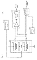
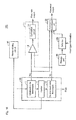
- Fig. 1 is a functional block diagram illustrating a schematic configuration of a thermal type flowmeter according to a first embodiment of the present invention.
- a thermal type flowmeter 101 of the first embodiment of the present invention includes a sensor element 10, an output circuit 11, a heater driving circuit 16, a storage unit 20, and an abnormality determination unit 22.
- the sensor element 10 includes an upstream-side thermopile 1, a heater 2, and a downstream-side thermopile 3.
- Each of the upstream-side thermopile 1 and the downstream-side thermopile 3 is a thermo-sensitive element that outputs a voltage changing according to a temperature.
- a voltage Vu is output from the upstream-side thermopile 1.
- a voltage Vd is output from the downstream-side thermopile 3.
- a direction in which a fluid flows is indicated by a dotted-line arrow.
- the upstream-side thermopile 1 is arranged on an upstream side of a flow passage with respect to the heater 2.
- the downstream-side thermopile 3 is arranged on a downstream side of the flow passage with respect to the heater 2.
- the heater 2 is driven by the heater driving circuit 16 to generate heat.
- the fluid (such as gas) flowing in the flow passage is heated by the heater 2.
- the heater driving circuit 16 supplies a current to the heater 2 to drive the heater 2.
- the output circuit 11 outputs a signal (flow rate output) expressing a flow rate based on a difference voltage between the output voltage Vu of the upstream-side thermopile 1 and the output voltage Vd of the downstream-side thermopile 3.
- the output circuit 11 includes a differential amplifier 12 and a correction circuit 14.
- the differential amplifier 12 amplifies the difference voltage between the output voltage Vu of the upstream-side thermopile 1 and the output voltage Vd of the downstream-side thermopile 3.
- the correction circuit 14 corrects an output voltage from the differential amplifier 12 to output a voltage changing according to the flow rate of the fluid.
- the correction circuit 14 is not always required. A configuration in which the correction circuit 14 is eliminated can be applied as the output circuit 11.
- a referential relationship is previously stored in the storage unit 20.
- a reference of a relationship between the output voltage Vu of the upstream-side thermopile 1 and the output voltage Vd of the downstream-side thermopile 3 is defined in the referential relationship.
- the "referential relationship" is stored in the storage unit 20 as a two-dimensional map defined by the output voltage Vu of the upstream-side thermopile 1 and the output voltage Vd of the downstream-side thermopile 3.
- a form of the "referential relationship" stored in the storage unit 20 is not limited to the map.
- the "referential relationship" in the form of a table may be stored in the storage unit 20.
- the "referential relationship” may be stored in the storage unit 20 as a function in which one of the output voltages Vu and Vd is derived with the other as a variable.
- the abnormality determination unit 22 receives the output voltage Vu of the upstream-side thermopile 1 and the output voltage Vd of the downstream-side thermopile 3.
- the abnormality determination unit 22 determines an abnormality concerning the upstream-side thermopile 1 and downstream-side thermopile 3 based on the referential relationship between the output voltages Vu and Vd, the output voltage Vu of the upstream-side thermopile 1, and the output voltage Vd of the downstream-side thermopile 3.
- the referential relationship between the output voltages Vu and Vd is stored in the storage unit 20.
- the abnormality determination unit 22 compares one (for example, voltage Vu) of the output voltage Vu of the upstream-side thermopile 1 and the output voltage Vd of the downstream-side thermopile 3 to a reference value thereof.
- the abnormality determination unit 22 derives the reference value by applying the other (for example, voltage Vd) of the output voltage Vu of the upstream-side thermopile 1 and the output voltage Vd of the downstream-side thermopile 3 to the referential relationship.
- the abnormality determination unit 22 determines that the abnormality concerning the upstream-side thermopile 1 and downstream-side thermopile 3 is generated.
- the acceptable range may be fixed or adjustable.
- the abnormality determination unit 22 outputs a signal (abnormal output) indicating the abnormality concerning the upstream-side thermopile 1 or downstream-side thermopile 3.
- the abnormal output is transmitted to a circuit (not illustrated) that informs the abnormality of the thermal type flowmeter 101.
- the informing circuit is operated in response to the abnormal output.
- the informing circuit is, but not limited to, an LED or a buzzer.
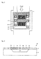
- Fig. 2 is a plan view illustrating a schematic configuration of the sensor element 10 in Fig. 1 .
- Fig. 3 is a schematic sectional view of the sensor element 10 in Fig. 2 .
- the sensor element 10 includes a silicon substrate 4 in which a cavity 5 is formed, the upstream-side thermopile 1, the heater 2, the downstream-side thermopile 3, and a temperature sensor 6.
- An insulating film 7 is formed on a surface of the silicon substrate 4.
- the upstream-side thermopile 1, the heater 2, the downstream-side thermopile 3, and the temperature sensor 6 are arranged in the insulating film 7.
- thermocouple is constructed with a poly-silicon (p-Si) wire and an aluminum (Al) wire, which are connected to each other, and has a cold junction and a hot junction.
- a hot junction 1 a of the upstream-side thermopile 1 and a hot junction 3a of the downstream-side thermopile 3 are arranged on the cavity 5.
- a cold junction 1b of the upstream-side thermopile 1 and a cold junction 3b of the downstream-side thermopile 3 are arranged on the silicon substrate 4. Because of high thermal conductivity of the silicon substrate 4, temperatures at the cold junctions 1b and 3b are identical to an ambient temperature of the sensor element 10. The ambient temperature of the sensor element 10 is equal to a temperature of the fluid before being heated by the heater 2.
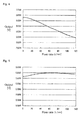
- Fig. 4 is a graph illustrating an exemplary characteristic of the upstream-side thermopile 1.
- Fig. 5 is a graph illustrating an exemplary characteristic of the downstream-side thermopile 3. Referring to the graphs in Figs. 4 and 5 , a horizontal axis indicates the flow rate of the fluid, and a vertical axis indicates the output voltage of the thermopile.
- the upstream-side thermopile 1 detects a temperature of the fluid before being heated.
- the upstream-side thermopile 1 generates thermoelectric power between the cold junction 1 b and the hot junction 1a by the heat of the fluid before being heated by the heater 2. Accordingly, the upstream-side thermopile 1 outputs the voltage Vu (see Fig. 1 ).
- the heat generated by the heater 2 is transmitted to the downstream-side thermopile 3 with the fluid as a medium.
- the downstream-side thermopile 3 generates the thermoelectric power by a temperature difference between the hot junction 3a and cold junction 3b of the downstream-side thermopile 3. Accordingly, the downstream-side thermopile 3 generates the voltage Vd (see Fig. 1 ).
- Fig. 6 is a graph illustrating a relationship between the voltage (flow rate output) output from the output circuit 11 in Fig. 1 and the flow rate.
- the voltage (flow rate output) from the output circuit changes depending on the flow rate of the fluid. Accordingly, the flow rate of the fluid can be understood by detecting the voltage of the flow rate output.
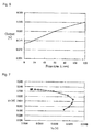
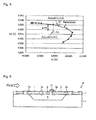
- Fig. 7 is a view illustrating an example of the referential relationship between the output voltage Vu of the upstream-side thermopile 1 and an output voltage Vd of the downstream-side thermopile 3. Referring to Fig. 7 , the voltages Vu and Vd change depending on the flow rate of the fluid.
- the referential relationship between the voltages Vu and Vd in Fig. 7 is previously stored in the storage unit 20 as a map.
- the map stored in the storage unit 20 is previously fixed by measurement with the sensor element of a reference. Therefore, the referential relationship between the voltages Vu and Vd is previously prepared.
- Fig. 8 is a view illustrating a concept of the abnormal determination concerning the upstream-side thermopile and the downstream-side thermopile.
- the referential relationship between the voltages Vu and Vd is defined in the map as a curve (hereinafter, referred to as a "reference curve").
- Each of points P1 and P2 plotted in the map indicates the actual output voltage (Vu,Vd).
- the point P1 is located relatively close to the reference curve. In this case, the upstream-side thermopile 1 and the downstream-side thermopile 3 are determined to be normal. On the other hand, the point P2 is located away from the reference curve with respect to the point P1.
- a difference ⁇ Vd indicates a difference between the actual voltage Vd and the voltage Vd (reference value) on the reference curve. In the case that the difference ⁇ Vd deviates from a predetermined acceptable range, the abnormality concerning the upstream-side thermopile 1 and the downstream-side thermopile 3 is determined.
- the abnormal determination is attributed to the change in sensitivity of the thermopile.
- a foreign substance such as dust and mist
- the sensitivity of the upstream-side thermopile 1 or downstream-side thermopile 3 can change.
- Fig. 9 is a schematic diagram illustrating the state in which the dust adheres to the surface of the sensor element.
- dust 31 included in the fluid adheres to a surface of the insulating film 7.
- the dust 31 is located on the downstream-side thermopile 3 (for example, on the hot junction 3a).
- the conduction of the heat generated by the heater 2 is changed by the dust 31.
- the heat conducts easily to the hot junction 3a of the downstream-side thermopile 3 through the dust 31. Therefore, the output voltage Vd of the downstream-side thermopile 3 changes.
- thermopile the point indicating the actual output voltage (Vu, Vd) is located out of the reference curve. Accordingly, the abnormality concerning the sensitivity of the thermopile can be detected.
- Fig. 10 is a flowchart illustrating the thermopile abnormality determination processing of the first embodiment of the present invention.
- the abnormality determination unit 22 repeatedly performs the processing of the flowchart in Fig. 10 in a constant period.
- the abnormality determination unit 22 acquires values of the output voltage Vu of the upstream-side thermopile 1 and the output voltage Vd of the downstream-side thermopile 3.
- the abnormality determination unit 22 receives the voltages Vu and Vd, and performs A/D conversion on the voltages Vu and Vd. Therefore, the abnormality determination unit 22 acquires values of voltages Vu and Vd.
- the acquired values of the voltages Vu and Vd are referred to as an "actual Vu value" and an "actual Vd value”.
- Step S2 the abnormality determination unit 22 reads the reference curve (see Fig. 7 ) in which the relationship between the voltages Vu and Vd is defined from the storage unit 20.
- Step S3 the abnormality determination unit 22 acquires an on-reference-curve Vd value corresponding to the actual Vu value.
- the Vd value is referred to as a "reference Vd value”.
- Step S4 the abnormality determination unit 22 acquires an on-reference-curve Vu value corresponding to the actual Vd value.
- the Vu value is referred to as a "reference Vu value”.
- Step S5 the abnormality determination unit 22 compares the reference Vd value to the actual Vd value. Specifically, the abnormality determination unit 22 determines whether a difference between the reference Vd value and the actual Vd value falls within a predetermined acceptable range.
- the term of "the difference between the reference Vd value and the actual Vd value" corresponds to the difference ⁇ Vd in Fig. 8 .
- Step S5 When the difference ⁇ Vd falls within the acceptable range (YES in Step S5), the processing goes to Step S6. On the other hand, when the difference ⁇ Vd is out of the acceptable range (NO in Step S5), the processing goes to Step S8.
- Step S6 the abnormality determination unit 22 compares the reference Vu value to the actual Vu value. Similarly to the processing in Step S5, the abnormality determination unit 22 determines whether a difference between the reference Vu value and the actual Vu value falls within a predetermined acceptable range.
- Step S6 When the difference between the reference Vu value and the actual Vu value falls within the acceptable range (YES in Step S6), the processing goes to Step S7. On the other hand, when the difference between the reference Vu value and the actual Vu value is out of the acceptable range (NO in Step S6), the processing goes to Step S8.
- Step S7 the abnormality determination unit 22 determines that the sensitivities of the upstream-side thermopile 1 and downstream-side thermopile 3 are normal. That is, the abnormality determination unit 22 determines that the sensitivities of the upstream-side thermopile 1 and downstream-side thermopile 3 are not abnormal.
- both the difference between the reference Vu value and the actual Vu value and the difference between the reference Vd value and the actual Vd value fall within the acceptable range. Accordingly, in this case, both the sensitivities of the upstream-side thermopile 1 and downstream-side thermopile 3 are determined to be normal.
- Step S8 the abnormality determination unit 22 determines that the sensitivity of at least one of the upstream-side thermopile 1 and the downstream-side thermopile 3 is abnormal.
- the actual Vu value and the actual Vd value are expressed as the point P2 in Fig. 8 , for example, the difference between the reference Vd value and the actual Vd value is out of the acceptable range. The difference between the reference Vu value and the actual Vu value is also out of the acceptable range. Accordingly, in this case, the sensitivity of at least one of the upstream-side thermopile 1 and the downstream-side thermopile 3 is determined to be abnormal.
- Step S9 the abnormality determination unit 22 outputs a signal (abnormal output) indicating the abnormality of the thermopile.
- the sequence of the pieces of processing is not limited to the sequence in Fig. 10 , but some pieces of sequence may properly be replaced.
- the plural pieces of processing may concurrently be performed.
- both the actual Vu value and the actual Vd value are determined only once.
- the actual Vu value may repeatedly be determined.
- the abnormality determination unit 22 may determine that the sensitivity of the thermopile is abnormal in the case that the determination result indicating the abnormality is continuously generated plural times.
- a set of the actual Vu value and the actual Vd value is acquired plural times, and plural points may be plotted on the map.
- the abnormal concerning sensitivity of the thermopile can be determined based on a distribution of the plural points.
- the thermal type flowmeter 101 detects the abnormality of the upstream-side thermopile 1 or downstream-side thermopile 3 by comparing the relationship between the output voltage Vu of the upstream-side thermopile 1 and the output voltage Vd of the downstream-side thermopile 3 to the referential relationship defined by the reference curve.
- the abnormality of the thermopile can be determined without the necessity to make the state different from the flow rate detection state such that the heater is turned off. Accordingly, in the first embodiment of the present invention, the abnormality of the thermopile can be determined while the flow rate of the fluid is detected.
- the abnormality of the thermopile can be determined without the necessity to wait for the thermal equilibrium state after the turn-on and -off of the heater.
- the usual flow rate detection processing and the abnormality determination processing can concurrently be performed using the output voltage Vu of the upstream-side thermopile 1 and the output voltage Vd of the downstream-side thermopile 3. Accordingly, time necessary for the determination processing can be shortened.
- the abnormality can continuously be determined because the time necessary for the determination processing can be shortened.
- the abnormality of the thermopile is determined in the case that the abnormal determination result is continuously generated plural times as described above. Therefore, a false determination due to an instantaneous malfunction caused by a noise can also be prevented.
- the continuously-obtained determination result may be stored in the storage unit 20 or a higher-level processor.
- a failure cause can be estimated by measuring the output voltage Vu of the upstream-side thermopile 1 and the output voltage Vd of the downstream-side thermopile 3 after the failure.
- the abnormality due to the adhesion of the foreign substance, such as dust and oil, to the sensor element can be detected by detecting the change in sensitivity of the thermopile.
- the sensitivity of the thermopile changes in the case that the thermopile is degraded or damaged. Accordingly, the abnormality due to the degradation or damage of the thermopile can also be detected.
- a second embodiment provides a thermal type flowmeter that can determine the abnormality of the thermopile even if the temperature of the fluid changes.
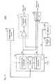
- Fig. 11 is a functional block diagram illustrating a schematic configuration of a thermal type flowmeter according to the second embodiment of the present invention.
- a thermal type flowmeter 102 of the second embodiment differs from the thermal type flowmeter 101 in Fig. 1 in that the thermal type flowmeter 102 further includes a temperature correcting circuit 24 (see Fig. 1 ).
- the sensor element 10 includes the temperature sensor 6 (see Fig. 2 ).
- the temperature sensor 6 measures the ambient temperature of the sensor element 10, and outputs a signal indicating a measured temperature Ta to the temperature correcting circuit 24.
- the temperature correcting circuit 24 reads the referential relationship between the output voltage Vu of the upstream-side thermopile 1 and the output voltage Vd of the downstream-side thermopile 3 from the storage unit 20, and corrects the "referential relationship" based on the temperature Ta measured by the temperature sensor 6.
- the abnormality determination unit 22 compares the relationship between the output voltages Vu and Vd to the corrected referential relationship to determine whether at least one of the upstream-side thermopile 1 and the downstream-side thermopile 3 is abnormal. Because other components of the configuration in Fig. 12 are identical to those in Fig. 1 , the description is omitted.
- Fig. 12 is a view illustrating an example of temperature dependence on the relationship between the output voltage Vu of the upstream-side thermopile 1 and the output voltage Vd of the downstream-side thermopile 3.
- the relationship between the voltages Vu and Vd changes depending on the ambient temperature Ta of the sensor element 10.
- the referential relationship stored in the storage unit 20 is corrected according to the ambient temperature Ta of the sensor element 10.
- the correction method there is no particular limitation in the correction method.
- the referential relationship between the voltages Vu and Vd can be corrected by adopting the following method.
- Fig. 13 is a view illustrating a configuration example of the data stored in the storage unit 20 of Fig. 12 .
- values (Vu1, Vd1, Vu2, Vd2, ⁇ ) of the voltages Vu and Vd are stored in the storage unit 20.
- the reference curve at the reference temperature is defined by the values of the voltages Vu and Vd.
- Correction factors ( ⁇ 1, ⁇ 2, ⁇ 3, ⁇ 1, ⁇ 2, ⁇ 3, ⁇ ) for the voltage Vd at temperature (A[°C], B[°C], C[°C], ⁇ ) different from the reference temperature are stored in the storage unit 20.
- the temperature correcting circuit 24 fixes the correction factor corresponding to each value of the voltage Vd stored in the storage unit 20.
- the temperature correcting circuit 24 multiplies the value of the voltage Vd stored in the storage unit 20 by the correction factor. Therefore, the referential relationship between the voltages Vu and Vd is corrected. In other words, the reference curve is corrected.
- the temperature correcting circuit 24 generates the correction factor using interpolation.
- interpolation method There is no particular limitation in the interpolation method, but various well-known methods can be adapted.
- the correction factor is set to the value of the voltage Vd.
- the setting of the correction factor is not limited to the value of the voltage Vd.
- the correction factor may be set to each value of the voltage Vu. That is, a configuration in which the voltage Vu is replaced with the voltage Vd in the data configuration of Fig. 13 can be applied to the second embodiment of the present invention.
- Fig. 14 is a flowchart illustrating thermopile abnormality determination processing of the second embodiment of the present invention.
- the abnormality determination processing of the second embodiment of the present invention differs from the abnormality determination processing of the first embodiment in that pieces of processing in Steps S1A and S2A are added.
- the pieces of processing in Steps S1A, S2A, and S2 are performed by the temperature correcting circuit 24.
- Step S1A the temperature correcting circuit 24 acquires the value of the ambient temperature Ta of the sensor element 10 from the temperature sensor 6.
- Step S2 the temperature correcting circuit 24 reads the reference curve from the storage unit 20.
- Step S2A the temperature correcting circuit 24 corrects the reference curve according to the above method.
- the reference Vd value obtained in Step S3 and the reference Vu value obtained in Step S4 are corrected values (values on the corrected reference curve).
- the ambient temperature of the sensor element 10 changes in the case that the temperature of the fluid changes.
- the abnormality of the thermopile cannot correctly be detected in the case that the sensitivity of the thermopile changes depending on the change in ambient temperature.
- the referential relationship stored in the storage unit 20 is corrected according to the ambient temperature of the sensor element 10. Accordingly, in the second embodiment of the present invention, the abnormality of the thermopile can correctly be determined even if the ambient temperature of the sensor element 10 changes.
- the ambient temperature of the sensor element 10 can change depending on the change in temperature of the fluid. In the second embodiment of the present invention, even in such cases, the abnormality of the thermopile can correctly be detected.
- the reference curve indicating the relationship between the voltages Vu and Vd varies depending on the ambient temperature. Accordingly, plural reference curves corresponding to different temperatures may be stored in the storage unit 20.
- Fig. 15 is a functional block diagram illustrating a schematic configuration of a modification of the thermal type flowmeter of the second embodiment of the present invention.
- a thermal type flowmeter 102A differs from the thermal type flowmeter 102 in that the thermal type flowmeter 102A includes a selector 24A instead of the temperature correcting circuit 24. Because other configurations of the thermal type flowmeter 102A are similar to those of the thermal type flowmeter 102, the overlapping description is omitted.
- the plural reference curves corresponding to different temperatures are stored in the storage unit 20.
- the selector 24A selects the reference curve corresponding to the ambient temperature Ta from the plural reference curves based on the ambient temperature Ta detected by the temperature sensor 6.
- the reference curve selected by the selector 24A is provided to the abnormality determination unit 22.
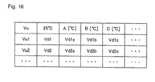
- Fig. 16 is a view illustrating a configuration example of the data stored in the storage unit 20 of Fig. 15 .
- the value of the voltage Vd corresponding to the voltage Vu is defined at each temperature.
- the reference curve is defined at each temperature by plural sets of (Vu,Vd) at each temperature.
- the selector 24A may select one of the reference curve of A[°C] and the reference curve of B[°C] (for example, the reference curve at the temperature closer to the measured temperature is selected).
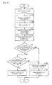
- Fig. 17 is a flowchart illustrating thermopile abnormality determination processing according to a modification of the second embodiment of the present invention.
- processing in Step S2B is performed instead of the pieces of processing in Steps S2A and S2.
- the selector 24A selects the reference curve corresponding to the ambient temperature Ta from the plural reference curves stored in the storage unit 20. Because the pieces of processing in other steps are similar to those in Fig. 10 or 14 , the overlapping description is omitted.
- the referential relationship is selected according to the ambient temperature of the sensor element 10. Accordingly, the abnormality of the thermopile can correctly be determined even if the ambient temperature of the sensor element 10 changes.
- the temperature correcting circuit 24 may be provided at a stage subsequent to the selector 24A. In this case, the temperature correcting circuit 24 corrects the reference curve selected by the selector 24A according to the ambient temperature Ta.
- the post-correction reference curve is provided to the abnormality determination unit 22. Even by the configuration, the abnormality of the thermopile can correctly be determined irrespective of the change in ambient temperature.
- a third embodiment provides a thermal type flowmeter that can determine the abnormality of the thermopile in the case that a flow speed of a different type of fluid is measured.
- Fig. 18 is a functional block diagram illustrating a schematic configuration of a modification of the thermal type flowmeter of the third embodiment of the present invention.
- a thermal type flowmeter 103 differs from the thermal type flowmeter 101 in that the thermal type flowmeter 103 further includes a selector 26. Because other configurations of the thermal type flowmeter 103 are similar to those of the thermal type flowmeter 101, the overlapping description is omitted.
- the selector 26 receives fluid type information on the type of the fluid.
- the selector 26 selects the reference curve corresponding to the fluid indicated by the fluid type information from the plural reference curves.
- the fluid type information may be provided to the selector 26 from an outside of the thermal type flowmeter 103.
- a signal indicating the fluid type information may be generated by a component such as a switch.
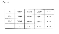
- Fig. 19 is a view illustrating a configuration example of the data stored in the storage unit 20 of Fig. 18 .
- plural types of gases for example, gases GasA, GasB, GasC, ⁇
- the value of the voltage Vd corresponding to the voltage Vu is defined in each type of the gas.
- the reference curve is defined in each type of the gas by the plural sets of (Vu,Vd) defined in each type of the gas.
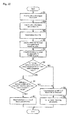
- Fig. 20 is a flowchart illustrating thermopile abnormality determination processing of the third embodiment of the present invention. Referring to Figs. 10 and 20 , the processing in Step S 1 B following the processing in Step S1 is performed in the abnormality determination processing of the third embodiment of the present invention. The processing in Step S2C is performed instead of the processing in Step S2.
- Step S1 B the selector 26 receives the fluid type information. Therefore, the selector 26 acquires the information on the type of the fluid.
- Step S2C the selector 26 selects the reference curve corresponding to the fluid type from the plural reference curves stored in the storage unit 20. Because the pieces of processing in other steps are similar to those in Fig. 10 , the overlapping description is omitted.
- the same effect as the first embodiment of the present invention can be obtained.
- the abnormality of the thermopile can be determined even if the fluid type varies.
- Fig. 21 is a view illustrating another configuration example of the thermal type flowmeter of the third embodiment of the present invention.
- the thermal type flowmeter 103A further includes a temperature correcting circuit 24.
- the temperature correcting circuit 24 corrects the reference curve selected by the selector 26 according to the ambient temperature Ta.
- a correction factor at each temperature is stored in the storage unit 20 according to each fluid type.
- the temperature correcting circuit 24 reads the correction factor from the storage unit 20 to correct the reference curve. In the configuration, the abnormality concerning the sensitivity of the thermopile can be determined even if the fluid type or the temperature varies.
- the thermal type flowmeter of each embodiment of the present invention can be used to measure the fluid in both commercial use and industrial use.
- the thermal type flowmeter of each embodiment can be used in, for example, gas flow rate measurement or differential pressure measurement of a gas meter and a gas boiler.
- Fig. 22 is a view illustrating an application example of the thermal type flowmeter of each embodiment of the present invention.
- the thermal type flowmeter 101 is provided in a gas line 111 to detect the flow rate of gas (gas fuel) flowing in the gas line 111.
- the gas flowing in the gas line 111 is delivered to a combustion device 115 while joining air flowing in the air line 112.
- One of thermal type flowmeters 102, 102A, 103, and 103A may be used instead of the thermal type flowmeter 101.
- a control valve 113 is provided in the gas line 111 in order to adjust the flow rate of the gas.
- a control device 114 controls the flow rate of the gas such that the flow rate of the gas becomes optimum (for example, an optimum air-fuel ratio is obtained).
- the control device 114 controls the control valve 113 in response to the signal (flow rate output) from the thermal type flowmeter 101.
- the thermal type flowmeter 101 may be arranged so as to detect a differential pressure between a pressure of the gas flowing in the gas line 111 and an atmospheric pressure or a differential pressure between the pressure of the gas flowing in the gas line 111 and a pressure of the air flowing in the air line 112.
- thermo-sensitive element is not limited to the thermopile as long as the thermo-sensitive element is an element that changes the output voltage according to the temperature.
- a thermistor can be used as the thermo-sensitive element.
- the output voltage of the thermo-sensitive element is used as the output signal output from the thermo-sensitive element (thermopile).
- a mode in which the output current of the thermo-sensitive element is used as the output signal output from the thermo-sensitive element can be included in the embodiment of the present invention.
- the "output voltage" in each of the embodiments is replaced with the "output current”
- the "referential relationship” is replaced with the relationship between the output current of the upstream-side thermo-sensitive element and the output current of the downstream-side thermo-sensitive element. Therefore, the abnormality concerning the sensitivities of the upstream-side thermo-sensitive element and downstream-side thermo-sensitive element can be detected.
- the output circuit may amplify the difference between an output current of the upstream-side thermo-sensitive element and an output current of the downstream-side thermo-sensitive element, and output a signal expressing the flow rate of the fluid.
- the output circuit may convert the output current of each thermo-sensitive element into the voltage, amplify the difference between the two voltages, and output a signal expressing the flow rate of the fluid.
- the determination that the upstream-side thermopile 1 and the downstream-side thermopile 3 are abnormal is made, when the difference between one of the voltage Vu output from the upstream-side thermopile 1 and the voltage Vd output from the downstream-side thermopile 3 and the reference value (reference Vu value or reference Vd value) derived from the referential relationship is out of the predetermined acceptable range (NO in Step S5 or NO in Step S6).
- the abnormality determination unit 22 may determine that the sensitivities of the upstream-side thermopile 1 and downstream-side thermopile 3 are abnormal, when the difference between the actual Vu value and the reference Vu value (first reference value) is out of the predetermined acceptable range, and when the difference between the actual Vd value and the reference Vd value (second reference value) is out of the predetermined acceptable range.
Landscapes
- Physics & Mathematics (AREA)
- General Physics & Mathematics (AREA)
- Fluid Mechanics (AREA)
- Engineering & Computer Science (AREA)
- Aviation & Aerospace Engineering (AREA)
- Measuring Volume Flow (AREA)
Abstract
Description
- The present invention relates to a thermal type flowmeter and a method for determining an abnormality thereof.
- There has been proposed a sensor chip measuring a flow rate of a fluid. For example, the sensor chip includes a semiconductor substrate constructed with a silicon substrate, a heater, and a pair of thermo-sensitive elements. One of the pair of thermo-sensitive elements is arranged on an upstream side of the flow passage with respect to the heater. The other thermo-sensitive element is arranged on a downstream side of the flow passage with respect to the heater.
- When the fluid such as gas flows in the flow passage, heat generated by the heater is transmitted to the downstream-side thermo-sensitive element. Accordingly, a difference is generated between a voltage output from the upstream-side thermo-sensitive element and a voltage output from the downstream-side thermo-sensitive element. The flow rate of the fluid is calculated based on the difference voltage.
- There has also been proposed a method for determining an abnormality of the sensor chip having the above configuration. For example, Japanese Unexamined Patent Publication No.
2000-321107 - Patent Document 1: Japanese Unexamined Patent Publication No.
2000-321107 - Japanese Unexamined Patent Publication No.
2000-321107 - However, generally the thermopile is covered with an insulating film. Accordingly, the resistance value of the thermopile does not change even if the dust adheres to a surface of the insulating film. That is, in the method disclosed in Japanese Unexamined Patent Publication No.
2000-321107 - In Japanese Unexamined Patent Publication No.
2000-321107 - A method for keeping the flow rate of the fluid constant or a method for decreasing the flow rate to zero is also conceivable instead of turning of the heater. However, in this case, it is also necessary to make a state different from the state of the usual flow rate detection.
- An object of the present invention is to provide a thermal type flowmeter that can determine the abnormality of the sensor element while detecting the flow rate of the fluid and an abnormality determination method thereof.
- One aspect of the present invention provides a thermal type flowmeter. The thermal type flowmeter includes a sensor element, an output circuit, a storage unit, and an abnormality determination unit. The sensor element includes a heater arranged in a flow passage in which a fluid flows to heat the fluid, a first thermo-sensitive element arranged on an upstream side of the flow passage with respect to the heater, and a second thermo-sensitive element arranged on a downstream side of the flow passage with respect to the heater. The output circuit outputs a signal expressing a flow rate of the fluid based on a difference between a first output signal output from the first thermo-sensitive element and a second output signal output from the second thermo-sensitive element. A referential relationship defining a reference of a relationship between the first output signal and the second output signal is previously stored in the storage unit. The abnormality determination unit determines an abnormality concerning the first and second thermo-sensitive elements by comparing a relationship between the first output signal output from the first thermo-sensitive element and the second output signal output from the second thermo-sensitive element to the referential relationship.
- Preferably the referential relationship is stored in the storage unit as one of a map defined by the first output signal and the second output signal, a table defined by the first output signal and the second output signal, and a function deriving one of the first output signal and the second output signal from the other.
- Preferably the thermal type flowmeter further includes: a temperature sensor configured to detect an ambient temperature of the sensor element; and a correction unit configured to correct the referential relationship based on the ambient temperature of the sensor element, the ambient temperature of the sensor element being detected by the temperature sensor.
- Preferably the thermal type flowmeter further includes: a temperature sensor configured to detect an ambient temperature of the sensor element; and a selector configured to select a relationship corresponding to the ambient temperature of the sensor element from plural referential relationships to provide the corresponding relationship to the abnormality determination unit, the ambient temperature of the sensor element being detected by the temperature sensor, each of the plural referential relationships being correlated with the ambient temperature of the sensor element. At this point, the storage unit includes the plural referential relationships as the referential relationship.
- Preferably the thermal type flowmeter further includes a selector configured to receive a type of the fluid, to select a relationship corresponding to the type of the fluid from plural referential relationships, and to provide the corresponding relationship to the abnormality determination unit, each of the plural referential relationships being correlated with the type of the fluid. At this point, the storage unit includes the plural referential relationships as the referential relationship.
- Preferably the abnormality determination unit determines that the abnormality concerning the first and second thermo-sensitive elements exists when a difference between one of the first output signal output from the first thermo-sensitive element and the second output signal output from the second thermo-sensitive element and a reference value derived from the referential relationship is out of a predetermined reference value. The abnormality determination unit generates the reference value by applying the other of the first output signal output from the first thermo-sensitive element and the second output signal output from the second thermo-sensitive element to the referential relationship.
- Preferably the abnormality determination unit determines that the abnormality concerning the first and second thermo-sensitive elements exists, when a difference between the first output signal output from the first thermo-sensitive element and a first reference value is out of a predetermined acceptable range, and when a difference between the second output signal output from the second thermo-sensitive element and a second reference value is out of a predetermined acceptable range. The abnormality determination unit generates the first reference value by applying the second output signal output from the second thermo-sensitive element to the referential relationship, and generates the second reference value by applying the first output signal output from the first thermo-sensitive element to the referential relationship.
- One aspect of the present invention provides a method for determining an abnormality of a thermal type flowmeter. The thermal type flowmeter includes a sensor element and an output circuit. The sensor element includes a heater arranged in a flow passage in which a fluid flows to heat the fluid, a first thermo-sensitive element arranged on an upstream side of the flow passage with respect to the heater, and a second thermo-sensitive element arranged on a downstream side of the flow passage with respect to the heater. The output circuit outputs a signal expressing a flow rate of the fluid based on a difference between a first output signal output from the first thermo-sensitive element and a second output signal output from the second thermo-sensitive element. The abnormality determination method includes the steps of: preparing a referential relationship defining a reference of a relationship between the first output signal and the second output signal; and determining the abnormality concerning the first and second thermo-sensitive elements by comparing a relationship between the first output signal output from the first thermo-sensitive element and the second output signal output from the second thermo-sensitive element to the referential relationship.
- In the present invention, while the flow rate of the fluid is detected with the thermal type flowmeter, the abnormality of the sensor element included in the thermal type flowmeter can be determined.
-
-
Fig. 1 is a functional block diagram illustrating a schematic configuration of a thermal type flowmeter according to a first embodiment of the present invention. -
Fig. 2 is a plan view illustrating a schematic configuration of a sensor element inFig. 1 . -
Fig. 3 is a schematic sectional view of the sensor element inFig. 2 . -
Fig. 4 is a graph illustrating an exemplary characteristic of an upstream-side thermopile. -
Fig. 5 is a graph illustrating an exemplary characteristic of a downstream-side thermopile. -
Fig. 6 is a graph illustrating a relationship between a voltage (flow rate output) output from an output circuit inFig. 1 and a flow rate. -
Fig. 7 is a view illustrating an example of a referential relationship between an output voltage of an upstream-side thermopile and an output voltage of a downstream-side thermopile. -
Fig. 8 is a view illustrating a concept of an abnormal determination concerning the upstream-side thermopile and the downstream-side thermopile. -
Fig. 9 is a schematic diagram illustrating a state in which dust adheres to a surface of a sensor element. -
Fig. 10 is a flowchart illustrating thermopile abnormality determination processing of the first embodiment of the present invention. -
Fig. 11 is a functional block diagram illustrating a schematic configuration of a thermal type flowmeter according to a second embodiment of the present invention. -
Fig. 12 is a view illustrating an example of temperature dependence on a relationship between the output voltage of the upstream-side thermopile and the output voltage of the downstream-side thermopile. -
Fig. 13 is a view illustrating a configuration example of data stored in a storage unit ofFig. 12 . -
Fig. 14 is a flowchart illustrating thermopile abnormality determination processing of the second embodiment of the present invention. -
Fig. 15 is a functional block diagram illustrating a schematic configuration of a modification of the thermal type flowmeter of the second embodiment of the present invention. -
Fig. 16 is a view illustrating a configuration example of data stored in a storage unit ofFig. 15 . -
Fig. 17 is a flowchart illustrating thermopile abnormality determination processing according to a modification of the second embodiment of the present invention. -
Fig. 18 is a functional block diagram illustrating a schematic configuration of a thermal type flowmeter according to a third embodiment of the present invention. -
Fig. 19 is a view illustrating a configuration example of data stored in a storage unit ofFig. 18 . -
Fig. 20 is a flowchart illustrating thermopile abnormality determination processing of the third embodiment of the present invention. -
Fig. 21 is a view illustrating another configuration example of the thermal type flowmeter of the third embodiment of the present invention. -
Fig. 22 is a view illustrating an application example of the thermal type flowmeter of each embodiment of the present invention. - Hereinafter, exemplary embodiments of the present invention will be described in detail with reference to the drawings. In the drawings, the identical or equivalent component is designated by the identical symbol.
-
Fig. 1 is a functional block diagram illustrating a schematic configuration of a thermal type flowmeter according to a first embodiment of the present invention. Referring toFig. 1 , athermal type flowmeter 101 of the first embodiment of the present invention includes asensor element 10, anoutput circuit 11, aheater driving circuit 16, astorage unit 20, and anabnormality determination unit 22. - The
sensor element 10 includes an upstream-side thermopile 1, aheater 2, and a downstream-side thermopile 3. Each of the upstream-side thermopile 1 and the downstream-side thermopile 3 is a thermo-sensitive element that outputs a voltage changing according to a temperature. A voltage Vu is output from the upstream-side thermopile 1. A voltage Vd is output from the downstream-side thermopile 3. - In
Fig. 1 , a direction in which a fluid flows is indicated by a dotted-line arrow. The upstream-side thermopile 1 is arranged on an upstream side of a flow passage with respect to theheater 2. The downstream-side thermopile 3 is arranged on a downstream side of the flow passage with respect to theheater 2. - The
heater 2 is driven by theheater driving circuit 16 to generate heat. The fluid (such as gas) flowing in the flow passage is heated by theheater 2. Theheater driving circuit 16 supplies a current to theheater 2 to drive theheater 2. - The
output circuit 11 outputs a signal (flow rate output) expressing a flow rate based on a difference voltage between the output voltage Vu of the upstream-side thermopile 1 and the output voltage Vd of the downstream-side thermopile 3. Theoutput circuit 11 includes adifferential amplifier 12 and acorrection circuit 14. Thedifferential amplifier 12 amplifies the difference voltage between the output voltage Vu of the upstream-side thermopile 1 and the output voltage Vd of the downstream-side thermopile 3. Thecorrection circuit 14 corrects an output voltage from thedifferential amplifier 12 to output a voltage changing according to the flow rate of the fluid. Thecorrection circuit 14 is not always required. A configuration in which thecorrection circuit 14 is eliminated can be applied as theoutput circuit 11. - A referential relationship is previously stored in the
storage unit 20. A reference of a relationship between the output voltage Vu of the upstream-side thermopile 1 and the output voltage Vd of the downstream-side thermopile 3 is defined in the referential relationship. For example, the "referential relationship" is stored in thestorage unit 20 as a two-dimensional map defined by the output voltage Vu of the upstream-side thermopile 1 and the output voltage Vd of the downstream-side thermopile 3. However, a form of the "referential relationship" stored in thestorage unit 20 is not limited to the map. For example, the "referential relationship" in the form of a table may be stored in thestorage unit 20. In another form, the "referential relationship" may be stored in thestorage unit 20 as a function in which one of the output voltages Vu and Vd is derived with the other as a variable. - The
abnormality determination unit 22 receives the output voltage Vu of the upstream-side thermopile 1 and the output voltage Vd of the downstream-side thermopile 3. Theabnormality determination unit 22 determines an abnormality concerning the upstream-side thermopile 1 and downstream-side thermopile 3 based on the referential relationship between the output voltages Vu and Vd, the output voltage Vu of the upstream-side thermopile 1, and the output voltage Vd of the downstream-side thermopile 3. The referential relationship between the output voltages Vu and Vd is stored in thestorage unit 20. - For example, the
abnormality determination unit 22 compares one (for example, voltage Vu) of the output voltage Vu of the upstream-side thermopile 1 and the output voltage Vd of the downstream-side thermopile 3 to a reference value thereof. Theabnormality determination unit 22 derives the reference value by applying the other (for example, voltage Vd) of the output voltage Vu of the upstream-side thermopile 1 and the output voltage Vd of the downstream-side thermopile 3 to the referential relationship. - In the case that at least one of sensitivity of the upstream-
side thermopile 1 and downstream-side thermopile 3 changes, for example, a difference between the actual voltage Vd and the reference value of the voltage Vd changes. Similarly, a difference between the actual voltage Vu and the reference value of the voltage Vu changes. In the case that one of these differences deviates from a predetermined acceptable range, theabnormality determination unit 22 determines that the abnormality concerning the upstream-side thermopile 1 and downstream-side thermopile 3 is generated. The acceptable range may be fixed or adjustable. - In the case that the abnormalities of the upstream-
side thermopile 1 and downstream-side thermopile 3 are determined, theabnormality determination unit 22 outputs a signal (abnormal output) indicating the abnormality concerning the upstream-side thermopile 1 or downstream-side thermopile 3. For example, the abnormal output is transmitted to a circuit (not illustrated) that informs the abnormality of thethermal type flowmeter 101. The informing circuit is operated in response to the abnormal output. For example, the informing circuit is, but not limited to, an LED or a buzzer. -
Fig. 2 is a plan view illustrating a schematic configuration of thesensor element 10 inFig. 1 .Fig. 3 is a schematic sectional view of thesensor element 10 inFig. 2 . Referring toFigs. 2 and 3 , thesensor element 10 includes asilicon substrate 4 in which acavity 5 is formed, the upstream-side thermopile 1, theheater 2, the downstream-side thermopile 3, and atemperature sensor 6. An insulatingfilm 7 is formed on a surface of thesilicon substrate 4. The upstream-side thermopile 1, theheater 2, the downstream-side thermopile 3, and thetemperature sensor 6 are arranged in the insulatingfilm 7. - Each of the upstream-
side thermopile 1 and the downstream-side thermopile 3 is constructed with a thermocouple. For example, the thermocouple is constructed with a poly-silicon (p-Si) wire and an aluminum (Al) wire, which are connected to each other, and has a cold junction and a hot junction. Ahot junction 1 a of the upstream-side thermopile 1 and ahot junction 3a of the downstream-side thermopile 3 are arranged on thecavity 5. On the other hand, acold junction 1b of the upstream-side thermopile 1 and acold junction 3b of the downstream-side thermopile 3 are arranged on thesilicon substrate 4. Because of high thermal conductivity of thesilicon substrate 4, temperatures at thecold junctions sensor element 10. The ambient temperature of thesensor element 10 is equal to a temperature of the fluid before being heated by theheater 2. -
Fig. 4 is a graph illustrating an exemplary characteristic of the upstream-side thermopile 1.Fig. 5 is a graph illustrating an exemplary characteristic of the downstream-side thermopile 3. Referring to the graphs inFigs. 4 and 5 , a horizontal axis indicates the flow rate of the fluid, and a vertical axis indicates the output voltage of the thermopile. - The upstream-
side thermopile 1 detects a temperature of the fluid before being heated. The upstream-side thermopile 1 generates thermoelectric power between thecold junction 1 b and thehot junction 1a by the heat of the fluid before being heated by theheater 2. Accordingly, the upstream-side thermopile 1 outputs the voltage Vu (seeFig. 1 ). - On the other hand, the heat generated by the
heater 2 is transmitted to the downstream-side thermopile 3 with the fluid as a medium. The downstream-side thermopile 3 generates the thermoelectric power by a temperature difference between thehot junction 3a andcold junction 3b of the downstream-side thermopile 3. Accordingly, the downstream-side thermopile 3 generates the voltage Vd (seeFig. 1 ). - Because a thermal distribution around the
heater 2 becomes symmetric at the flow rate of zero, the voltages Vu and Vd are equal to each other. When the fluid flows, the symmetry of the thermal distribution around theheater 2 collapses. Therefore, the difference is generated between the voltages Vu and Vd as illustrated inFigs. 4 and 5 . The difference between the voltages Vu and Vd changes depending on the flow rate of the fluid. -
Fig. 6 is a graph illustrating a relationship between the voltage (flow rate output) output from theoutput circuit 11 inFig. 1 and the flow rate. Referring toFig. 6 , the voltage (flow rate output) from the output circuit changes depending on the flow rate of the fluid. Accordingly, the flow rate of the fluid can be understood by detecting the voltage of the flow rate output. - A method for determining the abnormality of the thermal type flowmeter of the first embodiment of the present invention will be described in detail below.
Fig. 7 is a view illustrating an example of the referential relationship between the output voltage Vu of the upstream-side thermopile 1 and an output voltage Vd of the downstream-side thermopile 3. Referring toFig. 7 , the voltages Vu and Vd change depending on the flow rate of the fluid. - For example, the referential relationship between the voltages Vu and Vd in
Fig. 7 is previously stored in thestorage unit 20 as a map. For example, the map stored in thestorage unit 20 is previously fixed by measurement with the sensor element of a reference. Therefore, the referential relationship between the voltages Vu and Vd is previously prepared. -
Fig. 8 is a view illustrating a concept of the abnormal determination concerning the upstream-side thermopile and the downstream-side thermopile. Referring toFig. 8 , the referential relationship between the voltages Vu and Vd is defined in the map as a curve (hereinafter, referred to as a "reference curve"). Each of points P1 and P2 plotted in the map indicates the actual output voltage (Vu,Vd). - The point P1 is located relatively close to the reference curve. In this case, the upstream-
side thermopile 1 and the downstream-side thermopile 3 are determined to be normal. On the other hand, the point P2 is located away from the reference curve with respect to the point P1. - A difference ΔVd indicates a difference between the actual voltage Vd and the voltage Vd (reference value) on the reference curve. In the case that the difference ΔVd deviates from a predetermined acceptable range, the abnormality concerning the upstream-
side thermopile 1 and the downstream-side thermopile 3 is determined. - The abnormal determination is attributed to the change in sensitivity of the thermopile. For example, in the case that a foreign substance (such as dust and mist) included in the fluid adheres to the surface of the
sensor element 10, the sensitivity of the upstream-side thermopile 1 or downstream-side thermopile 3 can change. -
Fig. 9 is a schematic diagram illustrating the state in which the dust adheres to the surface of the sensor element. Referring toFig. 9 ,dust 31 included in the fluid adheres to a surface of the insulatingfilm 7. Thedust 31 is located on the downstream-side thermopile 3 (for example, on thehot junction 3a). The conduction of the heat generated by theheater 2 is changed by thedust 31. For example, the heat conducts easily to thehot junction 3a of the downstream-side thermopile 3 through thedust 31. Therefore, the output voltage Vd of the downstream-side thermopile 3 changes. - In such cases, as illustrated in
Fig. 8 , the point indicating the actual output voltage (Vu, Vd) is located out of the reference curve. Accordingly, the abnormality concerning the sensitivity of the thermopile can be detected. -
Fig. 10 is a flowchart illustrating the thermopile abnormality determination processing of the first embodiment of the present invention. For example, theabnormality determination unit 22 repeatedly performs the processing of the flowchart inFig. 10 in a constant period. - Referring to
Fig. 10 , in Step S1, theabnormality determination unit 22 acquires values of the output voltage Vu of the upstream-side thermopile 1 and the output voltage Vd of the downstream-side thermopile 3. For example, theabnormality determination unit 22 receives the voltages Vu and Vd, and performs A/D conversion on the voltages Vu and Vd. Therefore, theabnormality determination unit 22 acquires values of voltages Vu and Vd. Hereinafter, the acquired values of the voltages Vu and Vd are referred to as an "actual Vu value" and an "actual Vd value". - In Step S2, the
abnormality determination unit 22 reads the reference curve (seeFig. 7 ) in which the relationship between the voltages Vu and Vd is defined from thestorage unit 20. - In Step S3, the
abnormality determination unit 22 acquires an on-reference-curve Vd value corresponding to the actual Vu value. Hereinafter, the Vd value is referred to as a "reference Vd value". - In Step S4, the
abnormality determination unit 22 acquires an on-reference-curve Vu value corresponding to the actual Vd value. Hereinafter, the Vu value is referred to as a "reference Vu value". - In Step S5, the
abnormality determination unit 22 compares the reference Vd value to the actual Vd value. Specifically, theabnormality determination unit 22 determines whether a difference between the reference Vd value and the actual Vd value falls within a predetermined acceptable range. The term of "the difference between the reference Vd value and the actual Vd value" corresponds to the difference ΔVd inFig. 8 . - When the difference ΔVd falls within the acceptable range (YES in Step S5), the processing goes to Step S6. On the other hand, when the difference ΔVd is out of the acceptable range (NO in Step S5), the processing goes to Step S8.
- In Step S6, the
abnormality determination unit 22 compares the reference Vu value to the actual Vu value. Similarly to the processing in Step S5, theabnormality determination unit 22 determines whether a difference between the reference Vu value and the actual Vu value falls within a predetermined acceptable range. - When the difference between the reference Vu value and the actual Vu value falls within the acceptable range (YES in Step S6), the processing goes to Step S7. On the other hand, when the difference between the reference Vu value and the actual Vu value is out of the acceptable range (NO in Step S6), the processing goes to Step S8.
- In Step S7, the
abnormality determination unit 22 determines that the sensitivities of the upstream-side thermopile 1 and downstream-side thermopile 3 are normal. That is, theabnormality determination unit 22 determines that the sensitivities of the upstream-side thermopile 1 and downstream-side thermopile 3 are not abnormal. - In the case that the actual Vu value and the actual Vd value are expressed as the point P1 in
Fig. 8 , both the difference between the reference Vu value and the actual Vu value and the difference between the reference Vd value and the actual Vd value fall within the acceptable range. Accordingly, in this case, both the sensitivities of the upstream-side thermopile 1 and downstream-side thermopile 3 are determined to be normal. - On the other hand, in Step S8, the
abnormality determination unit 22 determines that the sensitivity of at least one of the upstream-side thermopile 1 and the downstream-side thermopile 3 is abnormal. In the case that the actual Vu value and the actual Vd value are expressed as the point P2 inFig. 8 , for example, the difference between the reference Vd value and the actual Vd value is out of the acceptable range. The difference between the reference Vu value and the actual Vu value is also out of the acceptable range. Accordingly, in this case, the sensitivity of at least one of the upstream-side thermopile 1 and the downstream-side thermopile 3 is determined to be abnormal. - In Step S9, the
abnormality determination unit 22 outputs a signal (abnormal output) indicating the abnormality of the thermopile. - The sequence of the pieces of processing is not limited to the sequence in
Fig. 10 , but some pieces of sequence may properly be replaced. The plural pieces of processing may concurrently be performed. - In the flowchart of
Fig. 10 , both the actual Vu value and the actual Vd value are determined only once. Alternatively, for example, in the case that the abnormality of the actual Vu value is determined (the difference between the actual Vu value and the reference Vu value is out of the acceptable range), the actual Vu value may repeatedly be determined. Theabnormality determination unit 22 may determine that the sensitivity of the thermopile is abnormal in the case that the determination result indicating the abnormality is continuously generated plural times. - A set of the actual Vu value and the actual Vd value is acquired plural times, and plural points may be plotted on the map. For example, the abnormal concerning sensitivity of the thermopile can be determined based on a distribution of the plural points.
- As described above, in the first embodiment of the present invention, the
thermal type flowmeter 101 detects the abnormality of the upstream-side thermopile 1 or downstream-side thermopile 3 by comparing the relationship between the output voltage Vu of the upstream-side thermopile 1 and the output voltage Vd of the downstream-side thermopile 3 to the referential relationship defined by the reference curve. In the first embodiment of the present invention, the abnormality of the thermopile can be determined without the necessity to make the state different from the flow rate detection state such that the heater is turned off. Accordingly, in the first embodiment of the present invention, the abnormality of the thermopile can be determined while the flow rate of the fluid is detected. - For example, in the case that the heater is turned off in order to determine the abnormality of the thermopile, it is necessary to wait for starting of determination processing until a thermal equilibrium state is obtained. Additionally, in the case that the heater is turned on, it is necessary to wait for the detection of flow rate until the thermal equilibrium state is obtained. On the other hand, in the first embodiment of the present invention, the abnormality of the thermopile can be determined without the necessity to wait for the thermal equilibrium state after the turn-on and -off of the heater. As illustrated in
Fig. 1 , in the first embodiment of the present invention, the usual flow rate detection processing and the abnormality determination processing can concurrently be performed using the output voltage Vu of the upstream-side thermopile 1 and the output voltage Vd of the downstream-side thermopile 3. Accordingly, time necessary for the determination processing can be shortened. - The abnormality can continuously be determined because the time necessary for the determination processing can be shortened. For example, the abnormality of the thermopile is determined in the case that the abnormal determination result is continuously generated plural times as described above. Therefore, a false determination due to an instantaneous malfunction caused by a noise can also be prevented.
- For example, the continuously-obtained determination result may be stored in the
storage unit 20 or a higher-level processor. For example, a failure cause can be estimated by measuring the output voltage Vu of the upstream-side thermopile 1 and the output voltage Vd of the downstream-side thermopile 3 after the failure. - In the first embodiment of the present invention, the abnormality due to the adhesion of the foreign substance, such as dust and oil, to the sensor element can be detected by detecting the change in sensitivity of the thermopile. For example, the sensitivity of the thermopile changes in the case that the thermopile is degraded or damaged. Accordingly, the abnormality due to the degradation or damage of the thermopile can also be detected.
- A second embodiment provides a thermal type flowmeter that can determine the abnormality of the thermopile even if the temperature of the fluid changes.
-
Fig. 11 is a functional block diagram illustrating a schematic configuration of a thermal type flowmeter according to the second embodiment of the present invention. Referring toFig. 11 , athermal type flowmeter 102 of the second embodiment differs from thethermal type flowmeter 101 inFig. 1 in that thethermal type flowmeter 102 further includes a temperature correcting circuit 24 (seeFig. 1 ). - The
sensor element 10 includes the temperature sensor 6 (seeFig. 2 ). Thetemperature sensor 6 measures the ambient temperature of thesensor element 10, and outputs a signal indicating a measured temperature Ta to thetemperature correcting circuit 24. - The
temperature correcting circuit 24 reads the referential relationship between the output voltage Vu of the upstream-side thermopile 1 and the output voltage Vd of the downstream-side thermopile 3 from thestorage unit 20, and corrects the "referential relationship" based on the temperature Ta measured by thetemperature sensor 6. Theabnormality determination unit 22 compares the relationship between the output voltages Vu and Vd to the corrected referential relationship to determine whether at least one of the upstream-side thermopile 1 and the downstream-side thermopile 3 is abnormal. Because other components of the configuration inFig. 12 are identical to those inFig. 1 , the description is omitted. -
Fig. 12 is a view illustrating an example of temperature dependence on the relationship between the output voltage Vu of the upstream-side thermopile 1 and the output voltage Vd of the downstream-side thermopile 3. Referring toFig. 12 , the relationship between the voltages Vu and Vd changes depending on the ambient temperature Ta of thesensor element 10. Accordingly, in the second embodiment, the referential relationship stored in thestorage unit 20 is corrected according to the ambient temperature Ta of thesensor element 10. There is no particular limitation in the correction method. For example, the referential relationship between the voltages Vu and Vd can be corrected by adopting the following method. -
Fig. 13 is a view illustrating a configuration example of the data stored in thestorage unit 20 ofFig. 12 . Referring toFig. 13 , for example, when the reference temperature is set to 25°C, values (Vu1, Vd1, Vu2, Vd2, ···) of the voltages Vu and Vd are stored in thestorage unit 20. The reference curve at the reference temperature is defined by the values of the voltages Vu and Vd. Correction factors (α1, α2, α3, β1, β2, β3, ···) for the voltage Vd at temperature (A[°C], B[°C], C[°C], ···) different from the reference temperature are stored in thestorage unit 20. - Based on the detected ambient temperature Ta, the
temperature correcting circuit 24 fixes the correction factor corresponding to each value of the voltage Vd stored in thestorage unit 20. Thetemperature correcting circuit 24 multiplies the value of the voltage Vd stored in thestorage unit 20 by the correction factor. Therefore, the referential relationship between the voltages Vu and Vd is corrected. In other words, the reference curve is corrected. - There is a possibility that the ambient temperature Ta detected by the
temperature sensor 6 is not matched with any temperature stored in thestorage unit 20. In such cases, for example, thetemperature correcting circuit 24 generates the correction factor using interpolation. There is no particular limitation in the interpolation method, but various well-known methods can be adapted. - In
Fig. 13 , the correction factor is set to the value of the voltage Vd. However, the setting of the correction factor is not limited to the value of the voltage Vd. The correction factor may be set to each value of the voltage Vu. That is, a configuration in which the voltage Vu is replaced with the voltage Vd in the data configuration ofFig. 13 can be applied to the second embodiment of the present invention. -
Fig. 14 is a flowchart illustrating thermopile abnormality determination processing of the second embodiment of the present invention. Referring toFigs. 10 and14 , the abnormality determination processing of the second embodiment of the present invention differs from the abnormality determination processing of the first embodiment in that pieces of processing in Steps S1A and S2A are added. In the second embodiment, the pieces of processing in Steps S1A, S2A, and S2 are performed by thetemperature correcting circuit 24. - For example, the processing in Step S1 is followed by the processing in Step S1A. In Step S1A, the
temperature correcting circuit 24 acquires the value of the ambient temperature Ta of thesensor element 10 from thetemperature sensor 6. - In Step S2, the
temperature correcting circuit 24 reads the reference curve from thestorage unit 20. In Step S2A, thetemperature correcting circuit 24 corrects the reference curve according to the above method. - Because the pieces of processing in other steps of the abnormality determination processing are identical to those of the first embodiment, the detailed description is omitted. In the second embodiment of the present invention, the reference Vd value obtained in Step S3 and the reference Vu value obtained in Step S4 are corrected values (values on the corrected reference curve).
- For example, there is a possibility that the ambient temperature of the
sensor element 10 changes in the case that the temperature of the fluid changes. There is a possibility that the abnormality of the thermopile cannot correctly be detected in the case that the sensitivity of the thermopile changes depending on the change in ambient temperature. In the second embodiment of the present invention, the referential relationship stored in thestorage unit 20 is corrected according to the ambient temperature of thesensor element 10. Accordingly, in the second embodiment of the present invention, the abnormality of the thermopile can correctly be determined even if the ambient temperature of thesensor element 10 changes. For example, the ambient temperature of thesensor element 10 can change depending on the change in temperature of the fluid. In the second embodiment of the present invention, even in such cases, the abnormality of the thermopile can correctly be detected. - As illustrated in
Fig. 12 , the reference curve indicating the relationship between the voltages Vu and Vd varies depending on the ambient temperature. Accordingly, plural reference curves corresponding to different temperatures may be stored in thestorage unit 20. -
Fig. 15 is a functional block diagram illustrating a schematic configuration of a modification of the thermal type flowmeter of the second embodiment of the present invention. Referring toFigs. 11 and15 , athermal type flowmeter 102A differs from thethermal type flowmeter 102 in that thethermal type flowmeter 102A includes aselector 24A instead of thetemperature correcting circuit 24. Because other configurations of thethermal type flowmeter 102A are similar to those of thethermal type flowmeter 102, the overlapping description is omitted. - As described above, the plural reference curves corresponding to different temperatures are stored in the
storage unit 20. Theselector 24A selects the reference curve corresponding to the ambient temperature Ta from the plural reference curves based on the ambient temperature Ta detected by thetemperature sensor 6. The reference curve selected by theselector 24A is provided to theabnormality determination unit 22. -
Fig. 16 is a view illustrating a configuration example of the data stored in thestorage unit 20 ofFig. 15 . Referring toFig. 16 , the value of the voltage Vd corresponding to the voltage Vu is defined at each temperature. The reference curve is defined at each temperature by plural sets of (Vu,Vd) at each temperature. In the case that the ambient temperature Ta detected by thetemperature sensor 6 is located between A[°C] and B[°C], for example, theselector 24A may select one of the reference curve of A[°C] and the reference curve of B[°C] (for example, the reference curve at the temperature closer to the measured temperature is selected). -
Fig. 17 is a flowchart illustrating thermopile abnormality determination processing according to a modification of the second embodiment of the present invention. Referring toFigs. 14 and17 , in the abnormality determination processing of the modification, processing in Step S2B is performed instead of the pieces of processing in Steps S2A and S2. In Step S2B, theselector 24A selects the reference curve corresponding to the ambient temperature Ta from the plural reference curves stored in thestorage unit 20. Because the pieces of processing in other steps are similar to those inFig. 10 or14 , the overlapping description is omitted. - In the configuration, the referential relationship is selected according to the ambient temperature of the
sensor element 10. Accordingly, the abnormality of the thermopile can correctly be determined even if the ambient temperature of thesensor element 10 changes. - The
temperature correcting circuit 24 may be provided at a stage subsequent to theselector 24A. In this case, thetemperature correcting circuit 24 corrects the reference curve selected by theselector 24A according to the ambient temperature Ta. The post-correction reference curve is provided to theabnormality determination unit 22. Even by the configuration, the abnormality of the thermopile can correctly be determined irrespective of the change in ambient temperature. - A third embodiment provides a thermal type flowmeter that can determine the abnormality of the thermopile in the case that a flow speed of a different type of fluid is measured.
-
Fig. 18 is a functional block diagram illustrating a schematic configuration of a modification of the thermal type flowmeter of the third embodiment of the present invention. Referring toFigs. 1 and18 , athermal type flowmeter 103 differs from thethermal type flowmeter 101 in that thethermal type flowmeter 103 further includes aselector 26. Because other configurations of thethermal type flowmeter 103 are similar to those of thethermal type flowmeter 101, the overlapping description is omitted. - Plural reference curves corresponding to the different types of fluids are stored in the
storage unit 20. Theselector 26 receives fluid type information on the type of the fluid. Theselector 26 selects the reference curve corresponding to the fluid indicated by the fluid type information from the plural reference curves. - There is no particular limitation in a method for providing the fluid type information to the
selector 26. For example, the fluid type information may be provided to theselector 26 from an outside of thethermal type flowmeter 103. Alternatively, a signal indicating the fluid type information may be generated by a component such as a switch. -
Fig. 19 is a view illustrating a configuration example of the data stored in thestorage unit 20 ofFig. 18 . Referring toFig. 19 , plural types of gases (for example, gases GasA, GasB, GasC, ···) are defined as the liquid. The value of the voltage Vd corresponding to the voltage Vu is defined in each type of the gas. The reference curve is defined in each type of the gas by the plural sets of (Vu,Vd) defined in each type of the gas. -
Fig. 20 is a flowchart illustrating thermopile abnormality determination processing of the third embodiment of the present invention. Referring toFigs. 10 and20 , the processing in Step S 1 B following the processing in Step S1 is performed in the abnormality determination processing of the third embodiment of the present invention. The processing in Step S2C is performed instead of the processing in Step S2. - In Step S1 B, the
selector 26 receives the fluid type information. Therefore, theselector 26 acquires the information on the type of the fluid. In Step S2C, theselector 26 selects the reference curve corresponding to the fluid type from the plural reference curves stored in thestorage unit 20. Because the pieces of processing in other steps are similar to those inFig. 10 , the overlapping description is omitted. - In the third embodiment of the present invention, the same effect as the first embodiment of the present invention can be obtained. Particularly, in the third embodiment of the present invention, the abnormality of the thermopile can be determined even if the fluid type varies.
- The third embodiment of the present invention and the second embodiment of the present invention may be combined with each other.
Fig. 21 is a view illustrating another configuration example of the thermal type flowmeter of the third embodiment of the present invention. Referring toFigs. 18 and21 , thethermal type flowmeter 103A further includes atemperature correcting circuit 24. Thetemperature correcting circuit 24 corrects the reference curve selected by theselector 26 according to the ambient temperature Ta. - In addition to the data in
Fig. 19 , a correction factor at each temperature is stored in thestorage unit 20 according to each fluid type. Thetemperature correcting circuit 24 reads the correction factor from thestorage unit 20 to correct the reference curve. In the configuration, the abnormality concerning the sensitivity of the thermopile can be determined even if the fluid type or the temperature varies. - The thermal type flowmeter of each embodiment of the present invention can be used to measure the fluid in both commercial use and industrial use. The thermal type flowmeter of each embodiment can be used in, for example, gas flow rate measurement or differential pressure measurement of a gas meter and a gas boiler.
-
Fig. 22 is a view illustrating an application example of the thermal type flowmeter of each embodiment of the present invention. Referring toFig. 22 , thethermal type flowmeter 101 is provided in agas line 111 to detect the flow rate of gas (gas fuel) flowing in thegas line 111. The gas flowing in thegas line 111 is delivered to acombustion device 115 while joining air flowing in theair line 112. One ofthermal type flowmeters thermal type flowmeter 101. - A
control valve 113 is provided in thegas line 111 in order to adjust the flow rate of the gas. Using thecontrol valve 113, acontrol device 114 controls the flow rate of the gas such that the flow rate of the gas becomes optimum (for example, an optimum air-fuel ratio is obtained). Thecontrol device 114 controls thecontrol valve 113 in response to the signal (flow rate output) from thethermal type flowmeter 101. For example, thethermal type flowmeter 101 may be arranged so as to detect a differential pressure between a pressure of the gas flowing in thegas line 111 and an atmospheric pressure or a differential pressure between the pressure of the gas flowing in thegas line 111 and a pressure of the air flowing in theair line 112. - In each of the above embodiments, the sensor element in which the thermopile is used as the thermo-sensitive element is illustrated. However, the thermo-sensitive element is not limited to the thermopile as long as the thermo-sensitive element is an element that changes the output voltage according to the temperature. For example, a thermistor can be used as the thermo-sensitive element.
- In each of the above embodiments, the output voltage of the thermo-sensitive element (thermopile) is used as the output signal output from the thermo-sensitive element (thermopile). However, a mode in which the output current of the thermo-sensitive element is used as the output signal output from the thermo-sensitive element can be included in the embodiment of the present invention. In the mode, the "output voltage" in each of the embodiments is replaced with the "output current", the "referential relationship" is replaced with the relationship between the output current of the upstream-side thermo-sensitive element and the output current of the downstream-side thermo-sensitive element. Therefore, the abnormality concerning the sensitivities of the upstream-side thermo-sensitive element and downstream-side thermo-sensitive element can be detected. The output circuit may amplify the difference between an output current of the upstream-side thermo-sensitive element and an output current of the downstream-side thermo-sensitive element, and output a signal expressing the flow rate of the fluid. Alternatively, the output circuit may convert the output current of each thermo-sensitive element into the voltage, amplify the difference between the two voltages, and output a signal expressing the flow rate of the fluid.
- In the flowcharts of
Figs. 10 ,14 ,17 , and20 , the determination that the upstream-side thermopile 1 and the downstream-side thermopile 3 are abnormal is made, when the difference between one of the voltage Vu output from the upstream-side thermopile 1 and the voltage Vd output from the downstream-side thermopile 3 and the reference value (reference Vu value or reference Vd value) derived from the referential relationship is out of the predetermined acceptable range (NO in Step S5 or NO in Step S6). Alternatively, theabnormality determination unit 22 may determine that the sensitivities of the upstream-side thermopile 1 and downstream-side thermopile 3 are abnormal, when the difference between the actual Vu value and the reference Vu value (first reference value) is out of the predetermined acceptable range, and when the difference between the actual Vd value and the reference Vd value (second reference value) is out of the predetermined acceptable range. - It is noted that the disclosed embodiments are not restrictive but illustrative in every way. The scope of the present invention is not indicated by the above description but by the claims, and the meanings equivalent to the claims and all the changes within the claims are included in the present invention.
-
- 1
- upstream-side thermopile
- 1a,3a
- hot junction
- 1 b,3b
- cold junction
- 2
- heater
- 3
- downstream-side thermopile
- 4
- silicon substrate
- 5
- cavity
- 6
- temperature sensor
- 7
- insulating film
- 10
- sensor element
- 11
- output circuit
- 12
- differential amplifier
- 14
- correction circuit
- 16
- heater driving circuit
- 20
- storage unit
- 22
- abnormality determination unit
- 24
- temperature correcting circuit
- 24A,
- 26 selector
- 31
- dust
- 101, 102, 102A, 103, 103A
- thermal type flowmeter
- 111
- gas line
- 112
- air line
- 113
- control valve
- 114
- control device
- 115
- combustion device
- P1,P2
- point
Claims (8)
- A thermal type flowmeter comprising:a sensor element comprising a heater, a first thermo-sensitive element, and a second thermo-sensitive element, the heater being arranged in a flow passage in which a fluid flows to heat the fluid, the first thermo-sensitive element being arranged on an upstream side of the flow passage with respect to the heater, the second thermo-sensitive element being arranged on a downstream side of the flow passage with respect to the heater;an output circuit configured to output a signal expressing a flow rate of the fluid based on a difference between a first output signal output from the first thermo-sensitive element and a second output signal output from the second thermo-sensitive element;a storage unit in which a referential relationship is previously stored, the referential relationship defining a reference of a relationship between the first output signal and the second output signal; andan abnormality determination unit configured to determine an abnormality concerning the first and second thermo-sensitive elements by comparing a relationship between the first output signal output from the first thermo-sensitive element and the second output signal output from the second thermo-sensitive element to the referential relationship.
- The thermal type flowmeter according to claim 1, wherein the referential relationship is stored in the storage unit as one of a map defined by the first output signal and the second output signal, a table defined by the first output signal and the second output signal, and a function deriving one of the first output signal and the second output signal from the other.
- The thermal type flowmeter according to claim 1 or 2, further comprising:a temperature sensor configured to detect an ambient temperature of the sensor element; anda correction unit configured to correct the referential relationship based on the ambient temperature of the sensor element, the ambient temperature of the sensor element being detected by the temperature sensor.
- The thermal type flowmeter according to claim 1 or 2, further comprising:a temperature sensor configured to detect an ambient temperature of the sensor element; anda selector configured to select a relationship corresponding to the ambient temperature of the sensor element from a plurality of referential relationships to provide the corresponding relationship to the abnormality determination unit, the ambient temperature of the sensor element being detected by the temperature sensor,wherein the storage unit comprises the plurality of referential relationships as the referential relationship, each of the plurality of referential relationships being correlated with the ambient temperature of the sensor element.
- The thermal type flowmeter according to any one of claims 1 to 4, further comprising a selector configured to receive information on a type of the fluid, to select a relationship corresponding to the type of the fluid from a plurality of referential relationships, and to provide the corresponding relationship to the abnormality determination unit,
wherein the storage unit comprises the plurality of referential relationships as the referential relationship, each of the plurality of referential relationships being correlated with the type of the fluid. - The thermal type flowmeter according to any one of claims 1 to 5, wherein the abnormality determination unit determines that the abnormality concerning the first and second thermo-sensitive elements exists when a difference between one of the first output signal output from the first thermo-sensitive element and the second output signal output from the second thermo-sensitive element and a reference value derived from the referential relationship is out of a predetermined acceptable range, and
the abnormality determination unit generates the reference value by applying the other of the first output signal output from the first thermo-sensitive element and the second output signal output from the second thermo-sensitive element to the referential relationship. - The thermal type flowmeter according to any one of claims 1 to 6, wherein the abnormality determination unit determines that the abnormality concerning the first and second thermo-sensitive elements exists, when a difference between the first output signal output from the first thermo-sensitive element and a first reference value is out of a predetermined acceptable range, and when a difference between the second output signal output from the second thermo-sensitive element and a second reference value is out of a predetermined acceptable range, and
the abnormality determination unit generates the first reference value by applying the second output signal output from the second thermo-sensitive element to the referential relationship, and generates the second reference value by applying the first output signal output from the first thermo-sensitive element to the referential relationship. - A method for determining an abnormality of a thermal type flowmeter, the thermal type flowmeter comprising a sensor element and an output circuit, the sensor element comprising a heater, a first thermo-sensitive element, and a second thermo-sensitive element, the heater being arranged in a flow passage in which a fluid flows to heat the fluid, the first thermo-sensitive element being arranged on an upstream side of the flow passage with respect to the heater, the second thermo-sensitive element being arranged on a downstream side of the flow passage with respect to the heater, the output circuit outputting a signal expressing a flow rate of the fluid based on a difference between a first output signal output from the first thermo-sensitive element and a second output signal output from the second thermo-sensitive element,
the method comprising the steps of:preparing a referential relationship defining a reference of a relationship between the first output signal and the second output signal; anddetermining the abnormality concerning the first and second thermo-sensitive elements by comparing a relationship between the first output signal output from the first thermo-sensitive element and the second output signal output from the second thermo-sensitive element to the referential relationship.
Applications Claiming Priority (2)
| Application Number | Priority Date | Filing Date | Title |
|---|---|---|---|
| JP2012225821A JP5835182B2 (en) | 2012-10-11 | 2012-10-11 | Thermal flow meter and abnormality determination method thereof |
| PCT/JP2013/075466 WO2014057790A1 (en) | 2012-10-11 | 2013-09-20 | Thermal type flowmeter and method for determined abnormality thereof |
Publications (3)
| Publication Number | Publication Date |
|---|---|
| EP2908104A1 true EP2908104A1 (en) | 2015-08-19 |
| EP2908104A4 EP2908104A4 (en) | 2016-07-13 |
| EP2908104B1 EP2908104B1 (en) | 2021-06-09 |
Family
ID=50477261
Family Applications (1)
| Application Number | Title | Priority Date | Filing Date |
|---|---|---|---|
| EP13844854.3A Active EP2908104B1 (en) | 2012-10-11 | 2013-09-20 | Thermal type flowmeter and method for determining abnormality thereof |
Country Status (3)
| Country | Link |
|---|---|
| EP (1) | EP2908104B1 (en) |
| JP (1) | JP5835182B2 (en) |
| WO (1) | WO2014057790A1 (en) |
Families Citing this family (5)
| Publication number | Priority date | Publication date | Assignee | Title |
|---|---|---|---|---|
| JP7087415B2 (en) * | 2018-01-31 | 2022-06-21 | 株式会社デンソー | Rider device |
| US11402253B2 (en) * | 2018-06-26 | 2022-08-02 | Minebea Mitsumi Inc. | Fluid sensing apparatus and method for detecting failure of fluid sensor |
| JP7112373B2 (en) * | 2019-05-24 | 2022-08-03 | Mmiセミコンダクター株式会社 | flow sensor chip |
| JP7759719B2 (en) * | 2020-02-27 | 2025-10-24 | オムロン株式会社 | flow measuring device |
| CN119165191B (en) * | 2024-09-02 | 2025-09-19 | 北京航空航天大学 | Thermal flow velocity sensor and preparation method thereof |
Family Cites Families (9)
| Publication number | Priority date | Publication date | Assignee | Title |
|---|---|---|---|---|
| US4685331A (en) * | 1985-04-10 | 1987-08-11 | Innovus | Thermal mass flowmeter and controller |
| JP3067883B2 (en) * | 1992-02-20 | 2000-07-24 | トキコ株式会社 | Sensor device |
| JPH06229800A (en) * | 1993-02-03 | 1994-08-19 | Hitachi Metals Ltd | Mass flow sensor with abnormality diagnosis function and abnormality diagnosis method |
| JP3527657B2 (en) | 1999-05-10 | 2004-05-17 | 矢崎総業株式会社 | Flow sensor failure determination apparatus and method |
| JP3945385B2 (en) * | 2002-11-15 | 2007-07-18 | オムロン株式会社 | Flow sensor and flow measurement method |
| JP4558647B2 (en) * | 2003-11-20 | 2010-10-06 | 日立オートモティブシステムズ株式会社 | Thermal fluid flow meter |
| EP1965179B1 (en) * | 2007-02-28 | 2017-04-12 | Sensirion Holding AG | Flow detector device with self check |
| SI1972906T1 (en) * | 2007-03-19 | 2010-09-30 | Vaillant Gmbh | Method for recognising errors in a flow sensor |
| JP5511470B2 (en) * | 2010-03-30 | 2014-06-04 | アズビル株式会社 | Thermal flow meter, thermal gas type discrimination device, and automatic gas type judgment method |
-
2012
- 2012-10-11 JP JP2012225821A patent/JP5835182B2/en active Active
-
2013
- 2013-09-20 WO PCT/JP2013/075466 patent/WO2014057790A1/en not_active Ceased
- 2013-09-20 EP EP13844854.3A patent/EP2908104B1/en active Active
Also Published As
| Publication number | Publication date |
|---|---|
| JP5835182B2 (en) | 2015-12-24 |
| JP2014077711A (en) | 2014-05-01 |
| EP2908104B1 (en) | 2021-06-09 |
| EP2908104A4 (en) | 2016-07-13 |
| WO2014057790A1 (en) | 2014-04-17 |
Similar Documents
| Publication | Publication Date | Title |
|---|---|---|
| EP2908104B1 (en) | Thermal type flowmeter and method for determining abnormality thereof | |
| US8864378B2 (en) | Process variable transmitter with thermocouple polarity detection | |
| EP3719509B1 (en) | System and method for correcting current value of shunt resistor | |
| KR20010083072A (en) | Thermal flow sensor, method and apparatus for identifying fluid, flow sensor, and method and apparatus for flow measurement | |
| EP2924405A1 (en) | Intake air temperature sensor and flow measurement device | |
| JP4355792B2 (en) | Thermal flow meter | |
| US20160011031A1 (en) | Hot-Type Fluid Measurement Device | |
| US8388224B2 (en) | Engine turbine temperature measurement | |
| JP5450204B2 (en) | Flowmeter | |
| US8869604B2 (en) | Flow rate detection device | |
| US12601644B2 (en) | Thermometer with a diagnostic function | |
| EP3388805A1 (en) | Abnormal temperature detecting circuit | |
| US7467547B2 (en) | Fluid-measuring device and fluid-measuring method | |
| KR101434808B1 (en) | Method for determining a resulting total mass flow to an exhaust gas mass flow sensor | |
| US20120155506A1 (en) | System and method for detecting an unexpected medium or a change of medium sensed by a thermistor | |
| JP2002168663A (en) | Flow measurement device and leak detection device | |
| JP3527657B2 (en) | Flow sensor failure determination apparatus and method | |
| JP5522826B2 (en) | Thermal flow meter | |
| JP2004205376A (en) | Thermal mass flow sensor and gas combustion device | |
| JP5178264B2 (en) | Thermal flow meter | |
| JP4907959B2 (en) | Flow sensor correction unit, fluid discrimination device, and flow measurement device | |
| JP2001141539A (en) | Flow sensor temperature correction method and flow sensor circuit | |
| JP3766601B2 (en) | Flow sensor and flow measurement device | |
| JP2008256416A (en) | Flow detector | |
| JP2002350205A (en) | Flow measurement device using flow sensor |
Legal Events
| Date | Code | Title | Description |
|---|---|---|---|
| PUAI | Public reference made under article 153(3) epc to a published international application that has entered the european phase |
Free format text: ORIGINAL CODE: 0009012 |
|
| 17P | Request for examination filed |
Effective date: 20150501 |
|
| AK | Designated contracting states |
Kind code of ref document: A1 Designated state(s): AL AT BE BG CH CY CZ DE DK EE ES FI FR GB GR HR HU IE IS IT LI LT LU LV MC MK MT NL NO PL PT RO RS SE SI SK SM TR |
|
| AX | Request for extension of the european patent |
Extension state: BA ME |
|
| DAX | Request for extension of the european patent (deleted) | ||
| RA4 | Supplementary search report drawn up and despatched (corrected) |
Effective date: 20160613 |
|
| RIC1 | Information provided on ipc code assigned before grant |
Ipc: G01F 15/04 20060101ALI20160607BHEP Ipc: G01P 5/12 20060101ALI20160607BHEP Ipc: G01F 1/684 20060101ALI20160607BHEP Ipc: G01F 1/68 20060101AFI20160607BHEP Ipc: G01P 5/10 20060101ALI20160607BHEP Ipc: G01P 21/00 20060101ALI20160607BHEP Ipc: G01F 1/696 20060101ALI20160607BHEP |
|
| STAA | Information on the status of an ep patent application or granted ep patent |
Free format text: STATUS: EXAMINATION IS IN PROGRESS |
|
| 17Q | First examination report despatched |
Effective date: 20181024 |
|
| GRAP | Despatch of communication of intention to grant a patent |
Free format text: ORIGINAL CODE: EPIDOSNIGR1 |
|
| STAA | Information on the status of an ep patent application or granted ep patent |
Free format text: STATUS: GRANT OF PATENT IS INTENDED |
|
| INTG | Intention to grant announced |
Effective date: 20210208 |
|
| GRAS | Grant fee paid |
Free format text: ORIGINAL CODE: EPIDOSNIGR3 |
|
| GRAA | (expected) grant |
Free format text: ORIGINAL CODE: 0009210 |
|
| STAA | Information on the status of an ep patent application or granted ep patent |
Free format text: STATUS: THE PATENT HAS BEEN GRANTED |
|
| AK | Designated contracting states |
Kind code of ref document: B1 Designated state(s): AL AT BE BG CH CY CZ DE DK EE ES FI FR GB GR HR HU IE IS IT LI LT LU LV MC MK MT NL NO PL PT RO RS SE SI SK SM TR |
|
| REG | Reference to a national code |
Ref country code: GB Ref legal event code: FG4D |
|
| REG | Reference to a national code |
Ref country code: CH Ref legal event code: EP Ref country code: AT Ref legal event code: REF Ref document number: 1400893 Country of ref document: AT Kind code of ref document: T Effective date: 20210615 |
|
| REG | Reference to a national code |
Ref country code: DE Ref legal event code: R096 Ref document number: 602013077881 Country of ref document: DE |
|
| REG | Reference to a national code |
Ref country code: IE Ref legal event code: FG4D |
|
| REG | Reference to a national code |
Ref country code: LT Ref legal event code: MG9D |
|
| PG25 | Lapsed in a contracting state [announced via postgrant information from national office to epo] |
Ref country code: HR Free format text: LAPSE BECAUSE OF FAILURE TO SUBMIT A TRANSLATION OF THE DESCRIPTION OR TO PAY THE FEE WITHIN THE PRESCRIBED TIME-LIMIT Effective date: 20210609 Ref country code: LT Free format text: LAPSE BECAUSE OF FAILURE TO SUBMIT A TRANSLATION OF THE DESCRIPTION OR TO PAY THE FEE WITHIN THE PRESCRIBED TIME-LIMIT Effective date: 20210609 Ref country code: FI Free format text: LAPSE BECAUSE OF FAILURE TO SUBMIT A TRANSLATION OF THE DESCRIPTION OR TO PAY THE FEE WITHIN THE PRESCRIBED TIME-LIMIT Effective date: 20210609 Ref country code: BG Free format text: LAPSE BECAUSE OF FAILURE TO SUBMIT A TRANSLATION OF THE DESCRIPTION OR TO PAY THE FEE WITHIN THE PRESCRIBED TIME-LIMIT Effective date: 20210909 |
|
| REG | Reference to a national code |
Ref country code: AT Ref legal event code: MK05 Ref document number: 1400893 Country of ref document: AT Kind code of ref document: T Effective date: 20210609 |
|
| REG | Reference to a national code |
Ref country code: NL Ref legal event code: MP Effective date: 20210609 |
|
| PG25 | Lapsed in a contracting state [announced via postgrant information from national office to epo] |
Ref country code: GR Free format text: LAPSE BECAUSE OF FAILURE TO SUBMIT A TRANSLATION OF THE DESCRIPTION OR TO PAY THE FEE WITHIN THE PRESCRIBED TIME-LIMIT Effective date: 20210910 Ref country code: LV Free format text: LAPSE BECAUSE OF FAILURE TO SUBMIT A TRANSLATION OF THE DESCRIPTION OR TO PAY THE FEE WITHIN THE PRESCRIBED TIME-LIMIT Effective date: 20210609 Ref country code: NO Free format text: LAPSE BECAUSE OF FAILURE TO SUBMIT A TRANSLATION OF THE DESCRIPTION OR TO PAY THE FEE WITHIN THE PRESCRIBED TIME-LIMIT Effective date: 20210909 Ref country code: RS Free format text: LAPSE BECAUSE OF FAILURE TO SUBMIT A TRANSLATION OF THE DESCRIPTION OR TO PAY THE FEE WITHIN THE PRESCRIBED TIME-LIMIT Effective date: 20210609 Ref country code: SE Free format text: LAPSE BECAUSE OF FAILURE TO SUBMIT A TRANSLATION OF THE DESCRIPTION OR TO PAY THE FEE WITHIN THE PRESCRIBED TIME-LIMIT Effective date: 20210609 |
|
| PG25 | Lapsed in a contracting state [announced via postgrant information from national office to epo] |
Ref country code: CZ Free format text: LAPSE BECAUSE OF FAILURE TO SUBMIT A TRANSLATION OF THE DESCRIPTION OR TO PAY THE FEE WITHIN THE PRESCRIBED TIME-LIMIT Effective date: 20210609 Ref country code: EE Free format text: LAPSE BECAUSE OF FAILURE TO SUBMIT A TRANSLATION OF THE DESCRIPTION OR TO PAY THE FEE WITHIN THE PRESCRIBED TIME-LIMIT Effective date: 20210609 Ref country code: SM Free format text: LAPSE BECAUSE OF FAILURE TO SUBMIT A TRANSLATION OF THE DESCRIPTION OR TO PAY THE FEE WITHIN THE PRESCRIBED TIME-LIMIT Effective date: 20210609 Ref country code: SK Free format text: LAPSE BECAUSE OF FAILURE TO SUBMIT A TRANSLATION OF THE DESCRIPTION OR TO PAY THE FEE WITHIN THE PRESCRIBED TIME-LIMIT Effective date: 20210609 Ref country code: AT Free format text: LAPSE BECAUSE OF FAILURE TO SUBMIT A TRANSLATION OF THE DESCRIPTION OR TO PAY THE FEE WITHIN THE PRESCRIBED TIME-LIMIT Effective date: 20210609 Ref country code: PT Free format text: LAPSE BECAUSE OF FAILURE TO SUBMIT A TRANSLATION OF THE DESCRIPTION OR TO PAY THE FEE WITHIN THE PRESCRIBED TIME-LIMIT Effective date: 20211011 Ref country code: RO Free format text: LAPSE BECAUSE OF FAILURE TO SUBMIT A TRANSLATION OF THE DESCRIPTION OR TO PAY THE FEE WITHIN THE PRESCRIBED TIME-LIMIT Effective date: 20210609 Ref country code: NL Free format text: LAPSE BECAUSE OF FAILURE TO SUBMIT A TRANSLATION OF THE DESCRIPTION OR TO PAY THE FEE WITHIN THE PRESCRIBED TIME-LIMIT Effective date: 20210609 Ref country code: ES Free format text: LAPSE BECAUSE OF FAILURE TO SUBMIT A TRANSLATION OF THE DESCRIPTION OR TO PAY THE FEE WITHIN THE PRESCRIBED TIME-LIMIT Effective date: 20210609 |
|
| PG25 | Lapsed in a contracting state [announced via postgrant information from national office to epo] |
Ref country code: PL Free format text: LAPSE BECAUSE OF FAILURE TO SUBMIT A TRANSLATION OF THE DESCRIPTION OR TO PAY THE FEE WITHIN THE PRESCRIBED TIME-LIMIT Effective date: 20210609 |
|
| REG | Reference to a national code |
Ref country code: DE Ref legal event code: R097 Ref document number: 602013077881 Country of ref document: DE |
|
| PLBE | No opposition filed within time limit |
Free format text: ORIGINAL CODE: 0009261 |
|
| STAA | Information on the status of an ep patent application or granted ep patent |
Free format text: STATUS: NO OPPOSITION FILED WITHIN TIME LIMIT |
|
| PG25 | Lapsed in a contracting state [announced via postgrant information from national office to epo] |
Ref country code: DK Free format text: LAPSE BECAUSE OF FAILURE TO SUBMIT A TRANSLATION OF THE DESCRIPTION OR TO PAY THE FEE WITHIN THE PRESCRIBED TIME-LIMIT Effective date: 20210609 |
|
| REG | Reference to a national code |
Ref country code: CH Ref legal event code: PL |
|
| 26N | No opposition filed |
Effective date: 20220310 |
|
| REG | Reference to a national code |
Ref country code: BE Ref legal event code: MM Effective date: 20210930 |
|
| GBPC | Gb: european patent ceased through non-payment of renewal fee |
Effective date: 20210920 |
|
| PG25 | Lapsed in a contracting state [announced via postgrant information from national office to epo] |
Ref country code: MC Free format text: LAPSE BECAUSE OF FAILURE TO SUBMIT A TRANSLATION OF THE DESCRIPTION OR TO PAY THE FEE WITHIN THE PRESCRIBED TIME-LIMIT Effective date: 20210609 Ref country code: AL Free format text: LAPSE BECAUSE OF FAILURE TO SUBMIT A TRANSLATION OF THE DESCRIPTION OR TO PAY THE FEE WITHIN THE PRESCRIBED TIME-LIMIT Effective date: 20210609 |
|
| PG25 | Lapsed in a contracting state [announced via postgrant information from national office to epo] |
Ref country code: LU Free format text: LAPSE BECAUSE OF NON-PAYMENT OF DUE FEES Effective date: 20210920 Ref country code: IT Free format text: LAPSE BECAUSE OF FAILURE TO SUBMIT A TRANSLATION OF THE DESCRIPTION OR TO PAY THE FEE WITHIN THE PRESCRIBED TIME-LIMIT Effective date: 20210609 Ref country code: IE Free format text: LAPSE BECAUSE OF NON-PAYMENT OF DUE FEES Effective date: 20210920 Ref country code: GB Free format text: LAPSE BECAUSE OF NON-PAYMENT OF DUE FEES Effective date: 20210920 Ref country code: FR Free format text: LAPSE BECAUSE OF NON-PAYMENT OF DUE FEES Effective date: 20210930 Ref country code: BE Free format text: LAPSE BECAUSE OF NON-PAYMENT OF DUE FEES Effective date: 20210930 |
|
| PG25 | Lapsed in a contracting state [announced via postgrant information from national office to epo] |
Ref country code: LI Free format text: LAPSE BECAUSE OF NON-PAYMENT OF DUE FEES Effective date: 20210930 Ref country code: CH Free format text: LAPSE BECAUSE OF NON-PAYMENT OF DUE FEES Effective date: 20210930 |
|
| PG25 | Lapsed in a contracting state [announced via postgrant information from national office to epo] |
Ref country code: HU Free format text: LAPSE BECAUSE OF FAILURE TO SUBMIT A TRANSLATION OF THE DESCRIPTION OR TO PAY THE FEE WITHIN THE PRESCRIBED TIME-LIMIT; INVALID AB INITIO Effective date: 20130920 |
|
| PG25 | Lapsed in a contracting state [announced via postgrant information from national office to epo] |
Ref country code: CY Free format text: LAPSE BECAUSE OF FAILURE TO SUBMIT A TRANSLATION OF THE DESCRIPTION OR TO PAY THE FEE WITHIN THE PRESCRIBED TIME-LIMIT Effective date: 20210609 |
|
| PG25 | Lapsed in a contracting state [announced via postgrant information from national office to epo] |
Ref country code: MK Free format text: LAPSE BECAUSE OF FAILURE TO SUBMIT A TRANSLATION OF THE DESCRIPTION OR TO PAY THE FEE WITHIN THE PRESCRIBED TIME-LIMIT Effective date: 20210609 |
|
| PG25 | Lapsed in a contracting state [announced via postgrant information from national office to epo] |
Ref country code: MT Free format text: LAPSE BECAUSE OF FAILURE TO SUBMIT A TRANSLATION OF THE DESCRIPTION OR TO PAY THE FEE WITHIN THE PRESCRIBED TIME-LIMIT Effective date: 20210609 |
|
| PGFP | Annual fee paid to national office [announced via postgrant information from national office to epo] |
Ref country code: DE Payment date: 20250919 Year of fee payment: 13 |
|
| PG25 | Lapsed in a contracting state [announced via postgrant information from national office to epo] |
Ref country code: TR Free format text: LAPSE BECAUSE OF FAILURE TO SUBMIT A TRANSLATION OF THE DESCRIPTION OR TO PAY THE FEE WITHIN THE PRESCRIBED TIME-LIMIT Effective date: 20210609 |