EP2908029A2 - Electric generator oil pump driven gear - Google Patents
Electric generator oil pump driven gear Download PDFInfo
- Publication number
- EP2908029A2 EP2908029A2 EP15155282.5A EP15155282A EP2908029A2 EP 2908029 A2 EP2908029 A2 EP 2908029A2 EP 15155282 A EP15155282 A EP 15155282A EP 2908029 A2 EP2908029 A2 EP 2908029A2
- Authority
- EP
- European Patent Office
- Prior art keywords
- driven gear
- flange
- hub
- gear
- rotor
- Prior art date
- Legal status (The legal status is an assumption and is not a legal conclusion. Google has not performed a legal analysis and makes no representation as to the accuracy of the status listed.)
- Granted
Links
Images


Classifications
-
- F—MECHANICAL ENGINEERING; LIGHTING; HEATING; WEAPONS; BLASTING
- F16—ENGINEERING ELEMENTS AND UNITS; GENERAL MEASURES FOR PRODUCING AND MAINTAINING EFFECTIVE FUNCTIONING OF MACHINES OR INSTALLATIONS; THERMAL INSULATION IN GENERAL
- F16H—GEARING
- F16H55/00—Elements with teeth or friction surfaces for conveying motion; Worms, pulleys or sheaves for gearing mechanisms
- F16H55/02—Toothed members; Worms
- F16H55/17—Toothed wheels
-
- F—MECHANICAL ENGINEERING; LIGHTING; HEATING; WEAPONS; BLASTING
- F16—ENGINEERING ELEMENTS AND UNITS; GENERAL MEASURES FOR PRODUCING AND MAINTAINING EFFECTIVE FUNCTIONING OF MACHINES OR INSTALLATIONS; THERMAL INSULATION IN GENERAL
- F16H—GEARING
- F16H55/00—Elements with teeth or friction surfaces for conveying motion; Worms, pulleys or sheaves for gearing mechanisms
- F16H55/02—Toothed members; Worms
- F16H55/08—Profiling
-
- H—ELECTRICITY
- H02—GENERATION; CONVERSION OR DISTRIBUTION OF ELECTRIC POWER
- H02K—DYNAMO-ELECTRIC MACHINES
- H02K7/00—Arrangements for handling mechanical energy structurally associated with dynamo-electric machines, e.g. structural association with mechanical driving motors or auxiliary dynamo-electric machines
- H02K7/08—Structural association with bearings
-
- H—ELECTRICITY
- H02—GENERATION; CONVERSION OR DISTRIBUTION OF ELECTRIC POWER
- H02K—DYNAMO-ELECTRIC MACHINES
- H02K7/00—Arrangements for handling mechanical energy structurally associated with dynamo-electric machines, e.g. structural association with mechanical driving motors or auxiliary dynamo-electric machines
- H02K7/10—Structural association with clutches, brakes, gears, pulleys or mechanical starters
- H02K7/116—Structural association with clutches, brakes, gears, pulleys or mechanical starters with gears
-
- F—MECHANICAL ENGINEERING; LIGHTING; HEATING; WEAPONS; BLASTING
- F16—ENGINEERING ELEMENTS AND UNITS; GENERAL MEASURES FOR PRODUCING AND MAINTAINING EFFECTIVE FUNCTIONING OF MACHINES OR INSTALLATIONS; THERMAL INSULATION IN GENERAL
- F16H—GEARING
- F16H1/00—Toothed gearings for conveying rotary motion
- F16H1/02—Toothed gearings for conveying rotary motion without gears having orbital motion
- F16H1/04—Toothed gearings for conveying rotary motion without gears having orbital motion involving only two intermeshing members
- F16H1/06—Toothed gearings for conveying rotary motion without gears having orbital motion involving only two intermeshing members with parallel axes
-
- Y—GENERAL TAGGING OF NEW TECHNOLOGICAL DEVELOPMENTS; GENERAL TAGGING OF CROSS-SECTIONAL TECHNOLOGIES SPANNING OVER SEVERAL SECTIONS OF THE IPC; TECHNICAL SUBJECTS COVERED BY FORMER USPC CROSS-REFERENCE ART COLLECTIONS [XRACs] AND DIGESTS
- Y10—TECHNICAL SUBJECTS COVERED BY FORMER USPC
- Y10T—TECHNICAL SUBJECTS COVERED BY FORMER US CLASSIFICATION
- Y10T74/00—Machine element or mechanism
- Y10T74/19—Gearing
- Y10T74/19642—Directly cooperating gears
-
- Y—GENERAL TAGGING OF NEW TECHNOLOGICAL DEVELOPMENTS; GENERAL TAGGING OF CROSS-SECTIONAL TECHNOLOGIES SPANNING OVER SEVERAL SECTIONS OF THE IPC; TECHNICAL SUBJECTS COVERED BY FORMER USPC CROSS-REFERENCE ART COLLECTIONS [XRACs] AND DIGESTS
- Y10—TECHNICAL SUBJECTS COVERED BY FORMER USPC
- Y10T—TECHNICAL SUBJECTS COVERED BY FORMER US CLASSIFICATION
- Y10T74/00—Machine element or mechanism
- Y10T74/19—Gearing
- Y10T74/1987—Rotary bodies
Definitions
- This application relates to details of a gear which is driven to, in turn, drive an oil pump for a generator.
- Electrical generators are known and are often included in systems, such as a gas turbine engine.
- the generator generates electricity for use on an associated system.
- the electrical generator may generate electricity to power the gas turbine engine and, further, for uses on an associated aircraft.
- the generator includes a number of components which rotate at relatively high speeds. Some generators may also be powered to begin rotation of components in the gas turbine engine for use as a starter.
- Lubrication systems are known to provide lubricant to components within the electrical generator.
- an oil pump is typically driven by a shaft from the electrical generator.
- a shaft which is driven as part of the electrical generator carries a drive gear which engages a driven gear.
- the driven gear rotates a pump rotor for an oil pump which delivers oil back to the generator.
- a driven gear drives a radially outwardly extending flange.
- the radially outwardly extending flange extends along an axial distance defined along a center axis of the flange.
- the flange merges into a generally conical portion which, in turn, extends radially inwardly to a hub.
- the hub extends to a remote end.
- a first distance is defined between the remote end of the hub and an end of the flange that faces the remote end.
- a second distance is defined between ends of the flange.
- Gear teeth are formed at an outer periphery of the flange.
- a ratio of the first distance to the second distance is between 2.54 and 2.824.
- Figure 1 schematically shows a system 20 incorporating a gas turbine engine 22 which drives an electrical generator 24.
- the electrical generator 24 is driven by the gas turbine engine once the gas turbine engine is operating.
- the generator 24 may also be driven in an opposed direction to begin rotation of the gas turbine engine at start up.
- a hub 26 rotates with a shaft of the electrical generator and the hub 26 carries a drive gear 28.
- the drive gear 28 includes two distinct internal bore surfaces 46 and 48 with distinct portions on the hub 26 to properly position the gear 28.
- the gear 28 has gear teeth 32 which engage gear teeth 132 on a driven gear 30.
- Driven gear 30 is engaged to rotate a drive shaft 31 for an oil pump rotor 34.
- Oil pump rotor 34 is shown schematically delivering oil through line 36 back to components in the generator 24.
- Figure 1 further shows a rotor 302 which carries electrical components and a stator 300 which also carries electrical components.
- one of the components may be permanent magnets while the other is electrical coils.
- These components operate, as known, to generate electricity which is sent to a use 303, which may be to power the gas turbine engine 22 or may be for other uses on an aircraft.
- Figure 2 shows details of the drive gear 28.
- a hub extends from end 38 to a remote end 42.
- the gear teeth 32 extend between the end 42 and a ledge 40.
- a distance d 1 can be defined along an axis I between the ends 40 and 42 and is also an axial extent of the teeth 32.
- the hub includes a mount extending from the ledge 40 to end 38.
- d 2 An axial distance between the end 42 and the end 38 is shown as d 2 .
- d 1 was 0.220 inch (0.5588 centimeters) and d 2 was 0.423 inch (1.074442 centimeters).
- a ratio of d 1 to d 2 is between .520 and .544.
- cutouts 44 are formed in an end face at remote end 42.
- a ditch 50 is shown between the threaded radially inner bore portion 46 and the radially outer bore portion 48.
- a diameter d 3 to an outer diameter of the gear teeth 32 was 1.60 inches (4.06 centimeters).
- a ratio of d 3 to d 1 was between 6.93 and 7.28.
- Figure 3 shows an end of the drive gear 28 and shows there are four equal spaced cutouts 44, which are all cylindrical.
- Figure 4 shows a detail of a gear tooth 32.
- the curved sides 200 include four roll angles.
- a roll angle from a base of the side 200 to the point A was 7.66°. In embodiments, this roll angle is between 6.66 and 8.66.
- a roll angle X to the point B from the base of the side was 12.10° in one embodiment. In embodiments, the roll angle X was between 11.1° and 13.1 °.
- a roll angle Y to the point C was 25.4° in one embodiment. In embodiments, the roll angle Y was between 24.4° and 25.4°.
- the roll angle Z to the point D at the outer end of the side 200 was 29.9°. In embodiments, the angle Z was between 28.9° and 30.9°.
- Points A-D represent locations along the tooth where roll angles are inspected with A at tooth base, and D at tooth tip.
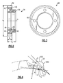
- Figure 5 shows details of the driven gear 30.
- the gear teeth 132 are at an outer periphery and extend between an end 60 to an end 70 of a radially outwardly extending flange 60. Holes 62 extend through the flange 60.
- a generally conical portion 64 merges the flange 60 into a base or hub 66.
- the hub 66 defines a remote end 68.
- a distance d 1 is defined along a central axis J between ends 68 and 70.
- a second diameter d 2 is defined along the axis J between ends 70 and 72.
- d 1 was 0.348 inch (0.88392 centimeters) and d 2 was 0.130 inch (0.3302 centimeters).
- a ratio of d 1 to d 2 was between 2.541 and 2.824.
- Figure 6 shows an end view of the gear 30. As shown, there are eight holes 62 each equally spaced about the axis J.
- the central hole 67 has opposed cylindrical portions 70 and intermediate flat portions 69.
- a distance to d 3 is defined through the axis J and between the flat portions 69.
- d 3 is .378 inch (0.96 centimeters).
- a ratio of d 3 to d 1 was between 1.06 and 1.10 inches (2.69 and 2.79 centimeters).
- the gear tooth 132 has angles L, M, N and O.
- the angle L to the point A along the side 202 was 14.42°.
- the angle L was between 13.42° and 15.42°.
- a roll angle M to the point B was 16.7°.
- the roll angle M is between 15.7° and 17.7°.
- the roll angle N to the point C was 23.54°.
- the roll angle N is between 22.54° and 24.54°.
- the roll angle O to the point D was 25.82°.
- the roll angle O is between 24.82° and 26.82°.
- the location of the gears 30 and 28 on the respective shafts is proper.
- the roll angles result in the gears transmitting rotation more effectively.
Landscapes
- Engineering & Computer Science (AREA)
- General Engineering & Computer Science (AREA)
- Mechanical Engineering (AREA)
- Power Engineering (AREA)
- Rotary Pumps (AREA)
- Connection Of Motors, Electrical Generators, Mechanical Devices, And The Like (AREA)
- Gears, Cams (AREA)
Abstract
Description
- This application relates to details of a gear which is driven to, in turn, drive an oil pump for a generator.
- Electrical generators are known and are often included in systems, such as a gas turbine engine. The generator generates electricity for use on an associated system. As an example, the electrical generator may generate electricity to power the gas turbine engine and, further, for uses on an associated aircraft.
- The generator includes a number of components which rotate at relatively high speeds. Some generators may also be powered to begin rotation of components in the gas turbine engine for use as a starter.
- Lubrication systems are known to provide lubricant to components within the electrical generator. In such systems, an oil pump is typically driven by a shaft from the electrical generator.
- In one known type of electrical generator, a shaft which is driven as part of the electrical generator carries a drive gear which engages a driven gear. The driven gear, in turn, rotates a pump rotor for an oil pump which delivers oil back to the generator.
- In the prior art, there have been challenges with properly mounting the drive and driven gears.
- A driven gear drives a radially outwardly extending flange. The radially outwardly extending flange extends along an axial distance defined along a center axis of the flange. The flange merges into a generally conical portion which, in turn, extends radially inwardly to a hub. The hub extends to a remote end. A first distance is defined between the remote end of the hub and an end of the flange that faces the remote end. A second distance is defined between ends of the flange. Gear teeth are formed at an outer periphery of the flange. A ratio of the first distance to the second distance is between 2.54 and 2.824. An oil pump, a rotating portion for an electrical generator, and a generator are also disclosed.
- These and other features may be best understood from the following drawings and specification.
-
-
Figure 1 schematically shows a generator and a drive pump. -
Figure 2 shows a drive gear. -
Figure 3 is an end view of theFigure 2 gear. -
Figure 4 shows a detail of a gear tooth. -
Figure 5 shows a driven gear. -
Figure 6 is an end view of the driven gear. -
Figure 7 shows a gear tooth for the driven gear. -
Figure 1 schematically shows asystem 20 incorporating agas turbine engine 22 which drives anelectrical generator 24. Theelectrical generator 24 is driven by the gas turbine engine once the gas turbine engine is operating. In addition, as known, thegenerator 24 may also be driven in an opposed direction to begin rotation of the gas turbine engine at start up. - A
hub 26 rotates with a shaft of the electrical generator and thehub 26 carries adrive gear 28. As shown, thedrive gear 28 includes two distinctinternal bore surfaces hub 26 to properly position thegear 28. - The
gear 28 hasgear teeth 32 which engagegear teeth 132 on a drivengear 30.Driven gear 30 is engaged to rotate adrive shaft 31 for anoil pump rotor 34.Oil pump rotor 34 is shown schematically delivering oil throughline 36 back to components in thegenerator 24. -
Figure 1 further shows arotor 302 which carries electrical components and astator 300 which also carries electrical components. In one example, one of the components may be permanent magnets while the other is electrical coils. These components operate, as known, to generate electricity which is sent to ause 303, which may be to power thegas turbine engine 22 or may be for other uses on an aircraft. -
Figure 2 shows details of thedrive gear 28. As shown, a hub extends fromend 38 to aremote end 42. Thegear teeth 32 extend between theend 42 and a ledge 40. A distance d1 can be defined along an axis I between theends teeth 32. The hub includes a mount extending from theledge 40 toend 38. - An axial distance between the
end 42 and theend 38 is shown as d2. In one embodiment, d1 was 0.220 inch (0.5588 centimeters) and d2 was 0.423 inch (1.074442 centimeters). In embodiments, a ratio of d1 to d2 is between .520 and .544. As further shown,cutouts 44 are formed in an end face atremote end 42. Aditch 50 is shown between the threaded radiallyinner bore portion 46 and the radiallyouter bore portion 48. - A diameter d3 to an outer diameter of the
gear teeth 32 was 1.60 inches (4.06 centimeters). A ratio of d3 to d1 was between 6.93 and 7.28. -
Figure 3 shows an end of thedrive gear 28 and shows there are four equalspaced cutouts 44, which are all cylindrical. -
Figure 4 shows a detail of agear tooth 32. As shown, there arecurved sides 200 and a relativelyflat end 202. Thecurved sides 200 include four roll angles. A roll angle from a base of theside 200 to the point A was 7.66°. In embodiments, this roll angle is between 6.66 and 8.66. A roll angle X to the point B from the base of the side was 12.10° in one embodiment. In embodiments, the roll angle X was between 11.1° and 13.1 °. A roll angle Y to the point C was 25.4° in one embodiment. In embodiments, the roll angle Y was between 24.4° and 25.4°. Finally, the roll angle Z to the point D at the outer end of theside 200 was 29.9°. In embodiments, the angle Z was between 28.9° and 30.9°. Points A-D represent locations along the tooth where roll angles are inspected with A at tooth base, and D at tooth tip. -
Figure 5 shows details of the drivengear 30. Thegear teeth 132 are at an outer periphery and extend between an end 60 to anend 70 of a radially outwardly extendingflange 60.Holes 62 extend through theflange 60. - A generally
conical portion 64 merges theflange 60 into a base orhub 66. Thehub 66 defines aremote end 68. A distance d1 is defined along a central axis J between ends 68 and 70. A second diameter d2 is defined along the axis J between ends 70 and 72. In one embodiment, d1 was 0.348 inch (0.88392 centimeters) and d2 was 0.130 inch (0.3302 centimeters). In embodiments, a ratio of d1 to d2 was between 2.541 and 2.824. -
Figure 6 shows an end view of thegear 30. As shown, there are eightholes 62 each equally spaced about the axis J. Thecentral hole 67 has opposedcylindrical portions 70 and intermediateflat portions 69. A distance to d3 is defined through the axis J and between theflat portions 69. In one embodiment, d3 is .378 inch (0.96 centimeters). In embodiments, a ratio of d3 to d1 was between 1.06 and 1.10 inches (2.69 and 2.79 centimeters). - As shown in
Figure 7 , thegear tooth 132 has angles L, M, N and O. In one embodiment, the angle L to the point A along theside 202 was 14.42°. In embodiments, the angle L was between 13.42° and 15.42°. In one embodiment, a roll angle M to the point B was 16.7°. In embodiments, the roll angle M is between 15.7° and 17.7°. In an embodiment, the roll angle N to the point C was 23.54°. In embodiments, the roll angle N is between 22.54° and 24.54°. In an embodiment, the roll angle O to the point D was 25.82°. In embodiments, the roll angle O is between 24.82° and 26.82°. - With the disclosed sizing and location of the various components, the location of the
gears - Although an embodiment of this invention has been disclosed, a worker of ordinary skill in this art would recognize that certain modifications would come within the scope of this invention. For that reason, the following claims should be studied to determine the true scope and content of this invention.
Claims (9)
- A driven gear (30) to drive an oil pump for a generator (24) comprising:a driven gear (30) including a radially outwardly extending flange (60), said radially outwardly extending flange (60) extending along an axial distance defined along a center axis of said flange (60), said flange (60) merging into a generally conical portion (64) which, in turn, extends radially inwardly to a hub (26), said hub (26) extending to a remote end (42), and a first distance defined between said remote end (42) of said hub (26) and an end of said flange (60) facing said remote end (42), and a second distance defined between ends of said flange (60), with gear teeth (32; 132) formed at an outer periphery of said flange (60); anda ratio of said first distance to said second distance being between 2.541 and 2.824.
- The driven gear (30) as set forth in claim 1, wherein said gear teeth (32; 132) have a flat outer end and curved sides, with there being four roll angles on each of said sides, with a first roll angle extending for 13.4° to 15.4°, a second roll angle extending for 15.7° to 17.7°, a third roll angle extending for 22.5° to 24.5°, and a fourth roll angle extending for 24.8° to 26.8°.
- The driven gear (30) as set forth in claim 1 or 2, wherein there are holes (62) extending through said flange (60).
- The driven gear (30) as set forth in claim 3, wherein there are eight of said holes (62) all being cylindrical and equally spaced about the central axis.
- The driven gear (30) as set forth in any preceding claim, wherein a central bore in said hub (26) includes a pair of generally cylindrical portions (70) extending about a portion of said axis, and opposed flat portions (69) between said generally cylindrical portions (70).
- The driven gear (30) as set forth in claim 5, wherein said flat portions (69) are spaced by a distance between .375 and .378 inches (0.95 and 0.96 centimeters).
- An oil pump for use in a generator (24) comprising:a drive gear (28) to be driven by a generator shaft and said drive gear (28) engaging a driven gear (30) as recited in any preceding claim, said driven gear (30) driving a pump rotor (34).
- A rotating portion for an electrical generator (24) comprising:a rotor hub (26) carrying a drive gear (28) to engage a driven gear (30) as claimed in claims 1 to 6; andsaid driven gear (30) driving an oil pump rotor (34).
- A generator (24) comprising:a stator (300), and a rotor (302), electrical components on said stator (300) and said rotor (302) interacting to generate electricity when said rotor (302) is rotated, said rotor (302) having a rotor hub (26), said rotor hub (26) carrying a drive gear (28), the drive gear (28) engaging a driven gear (30) as claimed in claims 1 to 6 which drives an oil pump.
Applications Claiming Priority (1)
| Application Number | Priority Date | Filing Date | Title |
|---|---|---|---|
| US14/181,849 US9494225B2 (en) | 2014-02-17 | 2014-02-17 | Electric generator oil pump driven gear |
Publications (3)
| Publication Number | Publication Date |
|---|---|
| EP2908029A2 true EP2908029A2 (en) | 2015-08-19 |
| EP2908029A3 EP2908029A3 (en) | 2016-05-25 |
| EP2908029B1 EP2908029B1 (en) | 2020-07-22 |
Family
ID=52473788
Family Applications (1)
| Application Number | Title | Priority Date | Filing Date |
|---|---|---|---|
| EP15155282.5A Active EP2908029B1 (en) | 2014-02-17 | 2015-02-16 | Electric generator oil pump driven gear |
Country Status (2)
| Country | Link |
|---|---|
| US (1) | US9494225B2 (en) |
| EP (1) | EP2908029B1 (en) |
Families Citing this family (3)
| Publication number | Priority date | Publication date | Assignee | Title |
|---|---|---|---|---|
| US10599165B2 (en) * | 2017-11-15 | 2020-03-24 | Hamilton Sundstrand Corporation | Governor and inversion pump drive gear |
| US11054012B2 (en) * | 2018-01-04 | 2021-07-06 | Hamilton Sundstrand Corporation | Generator driven gear for integrated drive generator |
| US10760665B2 (en) * | 2018-01-04 | 2020-09-01 | Hamilton Sundstrand Corporation | Governor drive gear for integrated drive generator |
Family Cites Families (18)
| Publication number | Priority date | Publication date | Assignee | Title |
|---|---|---|---|---|
| US1852538A (en) | 1929-10-11 | 1932-04-05 | Westinghouse Electric & Mfg Co | Damping means for gear wheels |
| US1813820A (en) | 1930-03-05 | 1931-07-07 | Gen Electric | Gear wheel and the like |
| DE2828473A1 (en) | 1978-06-29 | 1980-01-17 | Bosch Gmbh Robert | OIL COOLED ELECTRICAL MACHINE |
| US4201276A (en) | 1978-11-02 | 1980-05-06 | Bardin Viktor P | Vortex-type oil mist generator |
| JP2005088642A (en) | 2003-09-12 | 2005-04-07 | Kawasaki Heavy Ind Ltd | Vehicle hydraulic pressure generator |
| US20050151436A1 (en) * | 2004-01-14 | 2005-07-14 | Lantzy Scott R. | Gear motor assembly for floor care applications |
| JP4636506B2 (en) | 2006-02-28 | 2011-02-23 | 本田技研工業株式会社 | Cooling structure for vehicle generator |
| US8276396B2 (en) | 2006-12-29 | 2012-10-02 | Carrier Corporation | Oil cooled generator for trailer refrigeration unit |
| US8978501B2 (en) | 2008-12-10 | 2015-03-17 | Vestas Wind Systems A/S | Composite gear part for a gear arrangement and a method of forming a composite gear part |
| US8454326B2 (en) | 2009-05-08 | 2013-06-04 | Hamilton Sundstrand Corporation | Idler gear and journal bearing assembly for a generator |
| US8138642B2 (en) | 2009-06-17 | 2012-03-20 | Hamilton Sundstrand Corporation | Oil cooled generator |
| US7926381B2 (en) * | 2009-06-30 | 2011-04-19 | Hamilton Sundstrand Corporation | Idler gear for a generator |
| DE102010021771A1 (en) * | 2010-05-27 | 2011-12-01 | Schottel Gmbh | Bevel gear of a bevel gear |
| US8424416B2 (en) | 2010-06-18 | 2013-04-23 | Hamilton Sundstrand Corporation | Layshaft generator |
| JP5522106B2 (en) * | 2011-03-31 | 2014-06-18 | アイシン・エィ・ダブリュ株式会社 | Steel gear and manufacturing method thereof |
| JP2012219909A (en) | 2011-04-08 | 2012-11-12 | Denso Corp | Gear device and rotary actuator having the same |
| US8561503B2 (en) | 2011-07-28 | 2013-10-22 | Hamilton Sundstrand Corporation | Motor-generator and prime mover gearing assembly |
| US8624415B2 (en) | 2012-04-19 | 2014-01-07 | Hamilton Sundstrand Corporation | Multi-rotor generator |
-
2014
- 2014-02-17 US US14/181,849 patent/US9494225B2/en active Active
-
2015
- 2015-02-16 EP EP15155282.5A patent/EP2908029B1/en active Active
Non-Patent Citations (1)
| Title |
|---|
| None |
Also Published As
| Publication number | Publication date |
|---|---|
| US9494225B2 (en) | 2016-11-15 |
| EP2908029A3 (en) | 2016-05-25 |
| US20150233460A1 (en) | 2015-08-20 |
| EP2908029B1 (en) | 2020-07-22 |
Similar Documents
| Publication | Publication Date | Title |
|---|---|---|
| EP2908030B1 (en) | Electric generator oil pump drive gear | |
| US20100283341A1 (en) | Decoupler shaft for high speed generator | |
| US7926381B2 (en) | Idler gear for a generator | |
| EP2654185A3 (en) | Multi-rotor generator | |
| CN102338212B (en) | Planet axis in epicyclic gear system keeps | |
| EP3029814A3 (en) | Concentric ring generators | |
| EP2620622A2 (en) | Bevel gear arrangement for axial accessory gearbox | |
| EP3065275A1 (en) | Gas turbine engine with magnetic gearbox | |
| EP2908029B1 (en) | Electric generator oil pump driven gear | |
| CN105156216A (en) | Gas turbine and starting device thereof | |
| US10451163B2 (en) | Trim ring gear for integrated drive generator | |
| US10599165B2 (en) | Governor and inversion pump drive gear | |
| CN114174676A (en) | Improvements relating to main rotor turning systems for wind turbines | |
| EP3483443A1 (en) | Pump sleeve for integrated drive generator | |
| EP3467349B1 (en) | Accessory drive gear for integrated drive generator | |
| US10826342B2 (en) | Permanent magnet generator rotor for integrated drive generator | |
| EP3502514B1 (en) | Output ring gear for integrated drive generator | |
| US10760665B2 (en) | Governor drive gear for integrated drive generator | |
| US10883495B2 (en) | Scavenge/charge pump drive gear for integrated drive generator | |
| US11054012B2 (en) | Generator driven gear for integrated drive generator | |
| EP2755304B1 (en) | Rotor Gear Mounting Assembly for a Generator and Method | |
| TH83384B (en) | Rotary electric machinery |
Legal Events
| Date | Code | Title | Description |
|---|---|---|---|
| PUAI | Public reference made under article 153(3) epc to a published international application that has entered the european phase |
Free format text: ORIGINAL CODE: 0009012 |
|
| AK | Designated contracting states |
Kind code of ref document: A2 Designated state(s): AL AT BE BG CH CY CZ DE DK EE ES FI FR GB GR HR HU IE IS IT LI LT LU LV MC MK MT NL NO PL PT RO RS SE SI SK SM TR |
|
| AX | Request for extension of the european patent |
Extension state: BA ME |
|
| RIN1 | Information on inventor provided before grant (corrected) |
Inventor name: MANOGUE, BRADY A. Inventor name: BRUST, ERIC A. Inventor name: MARTIN, TED A. |
|
| PUAL | Search report despatched |
Free format text: ORIGINAL CODE: 0009013 |
|
| AK | Designated contracting states |
Kind code of ref document: A3 Designated state(s): AL AT BE BG CH CY CZ DE DK EE ES FI FR GB GR HR HU IE IS IT LI LT LU LV MC MK MT NL NO PL PT RO RS SE SI SK SM TR |
|
| AX | Request for extension of the european patent |
Extension state: BA ME |
|
| RIC1 | Information provided on ipc code assigned before grant |
Ipc: F16H 55/17 20060101AFI20160419BHEP |
|
| STAA | Information on the status of an ep patent application or granted ep patent |
Free format text: STATUS: REQUEST FOR EXAMINATION WAS MADE |
|
| RIN1 | Information on inventor provided before grant (corrected) |
Inventor name: MARTIN, TED A. Inventor name: MANOGUE, BRADY A. Inventor name: BRUST, ERIC A. |
|
| 17P | Request for examination filed |
Effective date: 20161123 |
|
| RBV | Designated contracting states (corrected) |
Designated state(s): AL AT BE BG CH CY CZ DE DK EE ES FI FR GB GR HR HU IE IS IT LI LT LU LV MC MK MT NL NO PL PT RO RS SE SI SK SM TR |
|
| GRAP | Despatch of communication of intention to grant a patent |
Free format text: ORIGINAL CODE: EPIDOSNIGR1 |
|
| STAA | Information on the status of an ep patent application or granted ep patent |
Free format text: STATUS: GRANT OF PATENT IS INTENDED |
|
| INTG | Intention to grant announced |
Effective date: 20200211 |
|
| RAP1 | Party data changed (applicant data changed or rights of an application transferred) |
Owner name: HAMILTON SUNDSTRAND CORPORATION |
|
| GRAS | Grant fee paid |
Free format text: ORIGINAL CODE: EPIDOSNIGR3 |
|
| GRAA | (expected) grant |
Free format text: ORIGINAL CODE: 0009210 |
|
| STAA | Information on the status of an ep patent application or granted ep patent |
Free format text: STATUS: THE PATENT HAS BEEN GRANTED |
|
| AK | Designated contracting states |
Kind code of ref document: B1 Designated state(s): AL AT BE BG CH CY CZ DE DK EE ES FI FR GB GR HR HU IE IS IT LI LT LU LV MC MK MT NL NO PL PT RO RS SE SI SK SM TR |
|
| REG | Reference to a national code |
Ref country code: GB Ref legal event code: FG4D |
|
| REG | Reference to a national code |
Ref country code: CH Ref legal event code: EP |
|
| REG | Reference to a national code |
Ref country code: DE Ref legal event code: R096 Ref document number: 602015056025 Country of ref document: DE |
|
| REG | Reference to a national code |
Ref country code: AT Ref legal event code: REF Ref document number: 1293689 Country of ref document: AT Kind code of ref document: T Effective date: 20200815 |
|
| REG | Reference to a national code |
Ref country code: IE Ref legal event code: FG4D |
|
| REG | Reference to a national code |
Ref country code: LT Ref legal event code: MG4D |
|
| REG | Reference to a national code |
Ref country code: AT Ref legal event code: MK05 Ref document number: 1293689 Country of ref document: AT Kind code of ref document: T Effective date: 20200722 |
|
| PG25 | Lapsed in a contracting state [announced via postgrant information from national office to epo] |
Ref country code: LT Free format text: LAPSE BECAUSE OF FAILURE TO SUBMIT A TRANSLATION OF THE DESCRIPTION OR TO PAY THE FEE WITHIN THE PRESCRIBED TIME-LIMIT Effective date: 20200722 Ref country code: ES Free format text: LAPSE BECAUSE OF FAILURE TO SUBMIT A TRANSLATION OF THE DESCRIPTION OR TO PAY THE FEE WITHIN THE PRESCRIBED TIME-LIMIT Effective date: 20200722 Ref country code: BG Free format text: LAPSE BECAUSE OF FAILURE TO SUBMIT A TRANSLATION OF THE DESCRIPTION OR TO PAY THE FEE WITHIN THE PRESCRIBED TIME-LIMIT Effective date: 20201022 Ref country code: FI Free format text: LAPSE BECAUSE OF FAILURE TO SUBMIT A TRANSLATION OF THE DESCRIPTION OR TO PAY THE FEE WITHIN THE PRESCRIBED TIME-LIMIT Effective date: 20200722 Ref country code: NO Free format text: LAPSE BECAUSE OF FAILURE TO SUBMIT A TRANSLATION OF THE DESCRIPTION OR TO PAY THE FEE WITHIN THE PRESCRIBED TIME-LIMIT Effective date: 20201022 Ref country code: GR Free format text: LAPSE BECAUSE OF FAILURE TO SUBMIT A TRANSLATION OF THE DESCRIPTION OR TO PAY THE FEE WITHIN THE PRESCRIBED TIME-LIMIT Effective date: 20201023 Ref country code: AT Free format text: LAPSE BECAUSE OF FAILURE TO SUBMIT A TRANSLATION OF THE DESCRIPTION OR TO PAY THE FEE WITHIN THE PRESCRIBED TIME-LIMIT Effective date: 20200722 Ref country code: SE Free format text: LAPSE BECAUSE OF FAILURE TO SUBMIT A TRANSLATION OF THE DESCRIPTION OR TO PAY THE FEE WITHIN THE PRESCRIBED TIME-LIMIT Effective date: 20200722 Ref country code: PT Free format text: LAPSE BECAUSE OF FAILURE TO SUBMIT A TRANSLATION OF THE DESCRIPTION OR TO PAY THE FEE WITHIN THE PRESCRIBED TIME-LIMIT Effective date: 20201123 Ref country code: HR Free format text: LAPSE BECAUSE OF FAILURE TO SUBMIT A TRANSLATION OF THE DESCRIPTION OR TO PAY THE FEE WITHIN THE PRESCRIBED TIME-LIMIT Effective date: 20200722 |
|
| PG25 | Lapsed in a contracting state [announced via postgrant information from national office to epo] |
Ref country code: IS Free format text: LAPSE BECAUSE OF FAILURE TO SUBMIT A TRANSLATION OF THE DESCRIPTION OR TO PAY THE FEE WITHIN THE PRESCRIBED TIME-LIMIT Effective date: 20201122 Ref country code: RS Free format text: LAPSE BECAUSE OF FAILURE TO SUBMIT A TRANSLATION OF THE DESCRIPTION OR TO PAY THE FEE WITHIN THE PRESCRIBED TIME-LIMIT Effective date: 20200722 Ref country code: PL Free format text: LAPSE BECAUSE OF FAILURE TO SUBMIT A TRANSLATION OF THE DESCRIPTION OR TO PAY THE FEE WITHIN THE PRESCRIBED TIME-LIMIT Effective date: 20200722 Ref country code: LV Free format text: LAPSE BECAUSE OF FAILURE TO SUBMIT A TRANSLATION OF THE DESCRIPTION OR TO PAY THE FEE WITHIN THE PRESCRIBED TIME-LIMIT Effective date: 20200722 |
|
| PG25 | Lapsed in a contracting state [announced via postgrant information from national office to epo] |
Ref country code: NL Free format text: LAPSE BECAUSE OF FAILURE TO SUBMIT A TRANSLATION OF THE DESCRIPTION OR TO PAY THE FEE WITHIN THE PRESCRIBED TIME-LIMIT Effective date: 20200722 |
|
| REG | Reference to a national code |
Ref country code: DE Ref legal event code: R097 Ref document number: 602015056025 Country of ref document: DE |
|
| PG25 | Lapsed in a contracting state [announced via postgrant information from national office to epo] |
Ref country code: SM Free format text: LAPSE BECAUSE OF FAILURE TO SUBMIT A TRANSLATION OF THE DESCRIPTION OR TO PAY THE FEE WITHIN THE PRESCRIBED TIME-LIMIT Effective date: 20200722 Ref country code: RO Free format text: LAPSE BECAUSE OF FAILURE TO SUBMIT A TRANSLATION OF THE DESCRIPTION OR TO PAY THE FEE WITHIN THE PRESCRIBED TIME-LIMIT Effective date: 20200722 Ref country code: EE Free format text: LAPSE BECAUSE OF FAILURE TO SUBMIT A TRANSLATION OF THE DESCRIPTION OR TO PAY THE FEE WITHIN THE PRESCRIBED TIME-LIMIT Effective date: 20200722 Ref country code: DK Free format text: LAPSE BECAUSE OF FAILURE TO SUBMIT A TRANSLATION OF THE DESCRIPTION OR TO PAY THE FEE WITHIN THE PRESCRIBED TIME-LIMIT Effective date: 20200722 Ref country code: CZ Free format text: LAPSE BECAUSE OF FAILURE TO SUBMIT A TRANSLATION OF THE DESCRIPTION OR TO PAY THE FEE WITHIN THE PRESCRIBED TIME-LIMIT Effective date: 20200722 Ref country code: IT Free format text: LAPSE BECAUSE OF FAILURE TO SUBMIT A TRANSLATION OF THE DESCRIPTION OR TO PAY THE FEE WITHIN THE PRESCRIBED TIME-LIMIT Effective date: 20200722 |
|
| PLBE | No opposition filed within time limit |
Free format text: ORIGINAL CODE: 0009261 |
|
| STAA | Information on the status of an ep patent application or granted ep patent |
Free format text: STATUS: NO OPPOSITION FILED WITHIN TIME LIMIT |
|
| PG25 | Lapsed in a contracting state [announced via postgrant information from national office to epo] |
Ref country code: AL Free format text: LAPSE BECAUSE OF FAILURE TO SUBMIT A TRANSLATION OF THE DESCRIPTION OR TO PAY THE FEE WITHIN THE PRESCRIBED TIME-LIMIT Effective date: 20200722 |
|
| 26N | No opposition filed |
Effective date: 20210423 |
|
| PG25 | Lapsed in a contracting state [announced via postgrant information from national office to epo] |
Ref country code: SK Free format text: LAPSE BECAUSE OF FAILURE TO SUBMIT A TRANSLATION OF THE DESCRIPTION OR TO PAY THE FEE WITHIN THE PRESCRIBED TIME-LIMIT Effective date: 20200722 |
|
| PG25 | Lapsed in a contracting state [announced via postgrant information from national office to epo] |
Ref country code: SI Free format text: LAPSE BECAUSE OF FAILURE TO SUBMIT A TRANSLATION OF THE DESCRIPTION OR TO PAY THE FEE WITHIN THE PRESCRIBED TIME-LIMIT Effective date: 20200722 |
|
| REG | Reference to a national code |
Ref country code: DE Ref legal event code: R119 Ref document number: 602015056025 Country of ref document: DE |
|
| PG25 | Lapsed in a contracting state [announced via postgrant information from national office to epo] |
Ref country code: MC Free format text: LAPSE BECAUSE OF FAILURE TO SUBMIT A TRANSLATION OF THE DESCRIPTION OR TO PAY THE FEE WITHIN THE PRESCRIBED TIME-LIMIT Effective date: 20200722 |
|
| REG | Reference to a national code |
Ref country code: NL Ref legal event code: MP Effective date: 20200722 |
|
| REG | Reference to a national code |
Ref country code: BE Ref legal event code: MM Effective date: 20210228 |
|
| PG25 | Lapsed in a contracting state [announced via postgrant information from national office to epo] |
Ref country code: CH Free format text: LAPSE BECAUSE OF NON-PAYMENT OF DUE FEES Effective date: 20210228 Ref country code: LI Free format text: LAPSE BECAUSE OF NON-PAYMENT OF DUE FEES Effective date: 20210228 Ref country code: LU Free format text: LAPSE BECAUSE OF NON-PAYMENT OF DUE FEES Effective date: 20210216 |
|
| PG25 | Lapsed in a contracting state [announced via postgrant information from national office to epo] |
Ref country code: DE Free format text: LAPSE BECAUSE OF NON-PAYMENT OF DUE FEES Effective date: 20210901 Ref country code: IE Free format text: LAPSE BECAUSE OF NON-PAYMENT OF DUE FEES Effective date: 20210216 |
|
| PG25 | Lapsed in a contracting state [announced via postgrant information from national office to epo] |
Ref country code: BE Free format text: LAPSE BECAUSE OF NON-PAYMENT OF DUE FEES Effective date: 20210228 |
|
| PG25 | Lapsed in a contracting state [announced via postgrant information from national office to epo] |
Ref country code: HU Free format text: LAPSE BECAUSE OF FAILURE TO SUBMIT A TRANSLATION OF THE DESCRIPTION OR TO PAY THE FEE WITHIN THE PRESCRIBED TIME-LIMIT; INVALID AB INITIO Effective date: 20150216 |
|
| P01 | Opt-out of the competence of the unified patent court (upc) registered |
Effective date: 20230522 |
|
| PG25 | Lapsed in a contracting state [announced via postgrant information from national office to epo] |
Ref country code: CY Free format text: LAPSE BECAUSE OF FAILURE TO SUBMIT A TRANSLATION OF THE DESCRIPTION OR TO PAY THE FEE WITHIN THE PRESCRIBED TIME-LIMIT Effective date: 20200722 |
|
| PG25 | Lapsed in a contracting state [announced via postgrant information from national office to epo] |
Ref country code: MK Free format text: LAPSE BECAUSE OF FAILURE TO SUBMIT A TRANSLATION OF THE DESCRIPTION OR TO PAY THE FEE WITHIN THE PRESCRIBED TIME-LIMIT Effective date: 20200722 |
|
| PG25 | Lapsed in a contracting state [announced via postgrant information from national office to epo] |
Ref country code: TR Free format text: LAPSE BECAUSE OF FAILURE TO SUBMIT A TRANSLATION OF THE DESCRIPTION OR TO PAY THE FEE WITHIN THE PRESCRIBED TIME-LIMIT Effective date: 20200722 |
|
| PG25 | Lapsed in a contracting state [announced via postgrant information from national office to epo] |
Ref country code: MT Free format text: LAPSE BECAUSE OF FAILURE TO SUBMIT A TRANSLATION OF THE DESCRIPTION OR TO PAY THE FEE WITHIN THE PRESCRIBED TIME-LIMIT Effective date: 20200722 |
|
| PGFP | Annual fee paid to national office [announced via postgrant information from national office to epo] |
Ref country code: GB Payment date: 20260122 Year of fee payment: 12 |
|
| PGFP | Annual fee paid to national office [announced via postgrant information from national office to epo] |
Ref country code: FR Payment date: 20260121 Year of fee payment: 12 |