EP2908001B1 - Mittel zur Verminderung der Belastung eines Windturbinenrotorblatts - Google Patents
Mittel zur Verminderung der Belastung eines Windturbinenrotorblatts Download PDFInfo
- Publication number
- EP2908001B1 EP2908001B1 EP14154895.8A EP14154895A EP2908001B1 EP 2908001 B1 EP2908001 B1 EP 2908001B1 EP 14154895 A EP14154895 A EP 14154895A EP 2908001 B1 EP2908001 B1 EP 2908001B1
- Authority
- EP
- European Patent Office
- Prior art keywords
- wind turbine
- buckling element
- rotor blade
- turbine rotor
- load
- Prior art date
- Legal status (The legal status is an assumption and is not a legal conclusion. Google has not performed a legal analysis and makes no representation as to the accuracy of the status listed.)
- Not-in-force
Links
- 238000005452 bending Methods 0.000 claims description 11
- 230000008859 change Effects 0.000 claims description 6
- 230000007423 decrease Effects 0.000 claims description 5
- 230000003247 decreasing effect Effects 0.000 claims description 5
- 230000001965 increasing effect Effects 0.000 description 6
- 230000008901 benefit Effects 0.000 description 4
- 239000000463 material Substances 0.000 description 4
- 230000007246 mechanism Effects 0.000 description 4
- 230000002159 abnormal effect Effects 0.000 description 3
- 238000012423 maintenance Methods 0.000 description 3
- 229920003023 plastic Polymers 0.000 description 3
- 239000004033 plastic Substances 0.000 description 3
- 230000009286 beneficial effect Effects 0.000 description 2
- 239000007769 metal material Substances 0.000 description 2
- 230000002035 prolonged effect Effects 0.000 description 2
- 230000002441 reversible effect Effects 0.000 description 2
- 230000004913 activation Effects 0.000 description 1
- 238000001994 activation Methods 0.000 description 1
- 230000001419 dependent effect Effects 0.000 description 1
- 230000000694 effects Effects 0.000 description 1
- 230000002708 enhancing effect Effects 0.000 description 1
- 238000004137 mechanical activation Methods 0.000 description 1
- 238000000034 method Methods 0.000 description 1
- 230000009467 reduction Effects 0.000 description 1
Images

Classifications
-
- F—MECHANICAL ENGINEERING; LIGHTING; HEATING; WEAPONS; BLASTING
- F03—MACHINES OR ENGINES FOR LIQUIDS; WIND, SPRING, OR WEIGHT MOTORS; PRODUCING MECHANICAL POWER OR A REACTIVE PROPULSIVE THRUST, NOT OTHERWISE PROVIDED FOR
- F03D—WIND MOTORS
- F03D7/00—Controlling wind motors
- F03D7/02—Controlling wind motors the wind motors having rotation axis substantially parallel to the air flow entering the rotor
- F03D7/022—Adjusting aerodynamic properties of the blades
- F03D7/0236—Adjusting aerodynamic properties of the blades by changing the active surface of the wind engaging parts, e.g. reefing or furling
-
- F—MECHANICAL ENGINEERING; LIGHTING; HEATING; WEAPONS; BLASTING
- F03—MACHINES OR ENGINES FOR LIQUIDS; WIND, SPRING, OR WEIGHT MOTORS; PRODUCING MECHANICAL POWER OR A REACTIVE PROPULSIVE THRUST, NOT OTHERWISE PROVIDED FOR
- F03D—WIND MOTORS
- F03D1/00—Wind motors with rotation axis substantially parallel to the air flow entering the rotor
- F03D1/06—Rotors
- F03D1/0608—Rotors characterised by their aerodynamic shape
- F03D1/0633—Rotors characterised by their aerodynamic shape of the blades
- F03D1/0641—Rotors characterised by their aerodynamic shape of the blades of the section profile of the blades, i.e. aerofoil profile
-
- F—MECHANICAL ENGINEERING; LIGHTING; HEATING; WEAPONS; BLASTING
- F03—MACHINES OR ENGINES FOR LIQUIDS; WIND, SPRING, OR WEIGHT MOTORS; PRODUCING MECHANICAL POWER OR A REACTIVE PROPULSIVE THRUST, NOT OTHERWISE PROVIDED FOR
- F03D—WIND MOTORS
- F03D1/00—Wind motors with rotation axis substantially parallel to the air flow entering the rotor
- F03D1/06—Rotors
- F03D1/065—Rotors characterised by their construction elements
- F03D1/0675—Rotors characterised by their construction elements of the blades
-
- F—MECHANICAL ENGINEERING; LIGHTING; HEATING; WEAPONS; BLASTING
- F03—MACHINES OR ENGINES FOR LIQUIDS; WIND, SPRING, OR WEIGHT MOTORS; PRODUCING MECHANICAL POWER OR A REACTIVE PROPULSIVE THRUST, NOT OTHERWISE PROVIDED FOR
- F03D—WIND MOTORS
- F03D7/00—Controlling wind motors
- F03D7/02—Controlling wind motors the wind motors having rotation axis substantially parallel to the air flow entering the rotor
- F03D7/0296—Controlling wind motors the wind motors having rotation axis substantially parallel to the air flow entering the rotor to prevent, counteract or reduce noise emissions
-
- F—MECHANICAL ENGINEERING; LIGHTING; HEATING; WEAPONS; BLASTING
- F05—INDEXING SCHEMES RELATING TO ENGINES OR PUMPS IN VARIOUS SUBCLASSES OF CLASSES F01-F04
- F05B—INDEXING SCHEME RELATING TO WIND, SPRING, WEIGHT, INERTIA OR LIKE MOTORS, TO MACHINES OR ENGINES FOR LIQUIDS COVERED BY SUBCLASSES F03B, F03D AND F03G
- F05B2240/00—Components
- F05B2240/20—Rotors
- F05B2240/30—Characteristics of rotor blades, i.e. of any element transforming dynamic fluid energy to or from rotational energy and being attached to a rotor
- F05B2240/305—Flaps, slats or spoilers
-
- F—MECHANICAL ENGINEERING; LIGHTING; HEATING; WEAPONS; BLASTING
- F05—INDEXING SCHEMES RELATING TO ENGINES OR PUMPS IN VARIOUS SUBCLASSES OF CLASSES F01-F04
- F05B—INDEXING SCHEME RELATING TO WIND, SPRING, WEIGHT, INERTIA OR LIKE MOTORS, TO MACHINES OR ENGINES FOR LIQUIDS COVERED BY SUBCLASSES F03B, F03D AND F03G
- F05B2240/00—Components
- F05B2240/20—Rotors
- F05B2240/30—Characteristics of rotor blades, i.e. of any element transforming dynamic fluid energy to or from rotational energy and being attached to a rotor
- F05B2240/31—Characteristics of rotor blades, i.e. of any element transforming dynamic fluid energy to or from rotational energy and being attached to a rotor of changeable form or shape
- F05B2240/311—Characteristics of rotor blades, i.e. of any element transforming dynamic fluid energy to or from rotational energy and being attached to a rotor of changeable form or shape flexible or elastic
-
- Y—GENERAL TAGGING OF NEW TECHNOLOGICAL DEVELOPMENTS; GENERAL TAGGING OF CROSS-SECTIONAL TECHNOLOGIES SPANNING OVER SEVERAL SECTIONS OF THE IPC; TECHNICAL SUBJECTS COVERED BY FORMER USPC CROSS-REFERENCE ART COLLECTIONS [XRACs] AND DIGESTS
- Y02—TECHNOLOGIES OR APPLICATIONS FOR MITIGATION OR ADAPTATION AGAINST CLIMATE CHANGE
- Y02E—REDUCTION OF GREENHOUSE GAS [GHG] EMISSIONS, RELATED TO ENERGY GENERATION, TRANSMISSION OR DISTRIBUTION
- Y02E10/00—Energy generation through renewable energy sources
- Y02E10/70—Wind energy
- Y02E10/72—Wind turbines with rotation axis in wind direction
Definitions
- the invention relates to an aerodynamic device which is attached to a wind turbine rotor blade and which is configured for alleviating strain on the wind turbine rotor blade.
- Aerodynamic devices which are attached to wind turbine rotor blades such as flaps or serrated panels are commonly used to enhance the aerodynamic performance of a wind turbine rotor during normal operation.
- an aerodynamic device can contribute to a strain of the wind turbine in an undesired way by considerably increasing the strain on some of the main components of the wind turbine such as the wind turbine rotor blades, the hub, the tower, and the main bearing.
- Solutions to this problem mainly relate to the use of active wind flow control mechanisms which control and regulate these aerodynamic devices in order to prevent high loads in abnormal operation conditions.
- the international patent application WO 2011/064214 proposes active flaps by the use of mechanical elements.
- the US patent 7,922,450 B2 uses piezoelectric elements to regulate a flap at the trailing edge of a wind turbine rotor blade.
- Aerodynamic devices or add-ons are not only used in the field of wind turbines but are also used in the field of helicopters.
- the option of using mechanical elements to control flaps or other aerodynamic devices is normally limited because the use of complex mechanisms which suffer e.g. from fatigue, icing or wear are problematic if applied to wind turbines.
- the use of electric components or piezoelectric components is usually in conflict with the requirements of the lightning protection systems for wind turbine rotor blades.
- the European patent application EP 2 647 835 A1 relates to a flap arrangement for a wind turbine rotor blade, which arrangement avoids active control mechanisms. Instead, the disclosed flap arrangement comprises a flap portion which is passively moveable with respect to a wind inflow angle. How ever, the disclosed concept is not aimed at reducing the strain on the rotor blade, but aims at providing a method for enhancing the aerodynamic performance of a wind turbine rotor blade.
- the US patent application US 2011/0042524 A1 discloses a concept how to passively mitigate aerodynamic loads. It comprises a structural insert which is inserted in the rotor blade body, e.g. as part of the suction side or pressure side shell of the rotor blade.
- an arrangement comprising a wind turbine rotor blade and an aerodynamic device, wherein the aerodynamic device is attached to the wind turbine rotor blade and comprises a buckling element.
- a stability limit and an elastic limit can be assigned to the buckling element, wherein the stability limit is smaller than the elastic limit.
- the buckling element is configured to deform elastically if a load, which is smaller than the elastic limit, acts on the buckling element.
- the buckling element abruptly deforms if a load of about the size of the stability limit acts on the buckling element, such that the aerodynamic properties of the arrangement change and strain on the wind turbine rotor blade is passively alleviated.
- One aspect of the invention is to alleviate strain on the wind turbine rotor blade, and thus, ultimately, enhance the aerodynamic performance of the wind turbine.
- the aerodynamic device which is also denoted as an aerodynamic add-on, is connected to the wind turbine rotor blade.
- the buckling element can solely be one (of several) parts of the aerodynamic device.
- the aerodynamic device consists of the buckling element.
- the buckling element may be the part that actually connects the wind turbine rotor blade and the remaining part(s) of the aerodynamic device, i.e. the remaining aerodynamic device.
- the aerodynamic device is configured such that its material properties already encompass a buckling functionality and thus the whole aerodynamic device can be described as the buckling element.
- the buckling element and the aerodynamic device build one entity.
- the buckling element and the aerodynamic device build one single item.
- the buckling element is the only direct connection between the remaining aerodynamic device and the wind turbine rotor blade. In another embodiment of the first alternative, the buckling element is one of several connections between the remaining aerodynamic device and the wind turbine rotor blade.
- a plurality of buckling elements connects the remaining aerodynamic device and the wind turbine rotor blade.
- the buckling element can have various shapes. It can e.g. have the shape of a plate or of a cylinder. It can also have any other suitable shape.
- a load generally refers to a force which is acting on an object, such as e.g. the buckling element.
- a load may act as a compressive force.
- a load may also induce a bending moment.
- the strain on the wind turbine or on parts of the wind turbine refers to, in the context of this application, more abstractly to the burden or loading of the wind turbine or parts of it, respectively.
- a first load limit of the buckling element is called the stability limit.
- the stability limit may be described as the point where the amount of deformation, or rate of deformation, abruptly changes. In other words, if a certain load acts on the buckling element, a certain deformation of the aerodynamic device results. If the load is approaching the stability limit, then an incremental increase of the load has the effect that the buckling element abruptly changes its shape and significantly deforms.
- a second load limit of the buckling element is its elastic limit.
- the elastic limit refers to a load which is greater than the stability limit.
- the elastic limit is defined such that for any load smaller than the elastic limit the buckling element behaves elastically. In other words, if the buckling element is deformed by a load which is smaller than the elastic limit and subsequently the buckling element is de-loaded, then the deformation also vanishes or disappears. Yet in other words, the deformation is a reversible deformation. Thus, if a load, e.g. a compressive force or a bending moment, is applied to the buckling element and the load is smaller than the stability limit, a certain deformation in a certain direction of the applied load occurs to the buckling element.
- a load e.g. a compressive force or a bending moment
- the deformation increases. This increase of the deformation may for example happen with a certain ratio. If the load reaches the stability limit, then the ratio of deformation changes abruptly. However, as long as the load is smaller than the elastic limit, this deformation is reversible. Only when exceeding the elastic limit, the buckling element is deformed in-elastically, i.e. irreversibly.
- the buckling element can be configured such that the stability limit corresponds to extreme loads where a fundamental change of the position of the aerodynamic device relative to the wind turbine rotor blade is desired.
- the buckling element deforms or buckles and thus gives the opportunity to alleviate the total strain which is experienced by the wind turbine, in particular the wind turbine rotor blade.
- the parameters of the buckling element e.g. regarding its material, its Young modulus and/or its thickness, buckling can be induced at predetermined conditions. At these predetermined conditions the structure becomes instable and prone to buckling.
- the equivalent aerodynamic properties, i.e. its aerodynamic characteristics, of the wind turbine rotor blade are modified in such a way that the lift at low angles of attack can be increased, while having a low penalty in maximum lift coefficient.
- the strain on the wind turbine rotor blade is in general both a function of the lift coefficient as well as of the relative flow speed of the wind flow. The strain may linearly increase with an increase in lift coefficient, and may increase proportionally to the square of the relative flow speed.
- the parameters of the buckling element can be carefully designed in order to induce buckling at the desired combination of lift coefficient and relative flow speed.
- a general advantage of the arrangement with the wind turbine rotor blade and the aerodynamic device is that the strain on the wind turbine in certain abnormal conditions is alleviated passively without having to implement mechanical activations, piezo-electrical elements, or other type of actuator elements such as pneumatic or hydraulic activations.
- a buckling element requires little maintenance and can be constructed reliably and robustly.
- the buckling element could be made of a plastic or metallic material.
- the metallic material be isolated due to potential lightning striking of the arrangement comprising the wind turbine rotor blade and the aerodynamic device.
- the ratio of the load acting on the buckling element and its deformation is substantially constant for loads that are smaller than the stability limit.
- the average ratio of the load acting on the buckling element and its deformation is smaller for loads between the stability limit and the elastic limit, compared to the average ratio of the load acting on the buckling element and its deformation for loads smaller than the stability limit.
- the ratio of the load and the deformation is not necessarily constant neither for loads smaller than the stability limit or for loads between the stability limit and the elastic limit, it may be advantageous to compare the respective average ratios instead of actual ratios.
- a load-deformation curve may be defined for characterizing the properties of the buckling element.
- the load-deformation curve is defined by the load acting on the buckling element versus its deformation.
- a first section and a second section can be assigned to the load-deformation curve, wherein the first section relates to loads smaller than the stability limit and the second section relates to loads between the stability limit and the elastic limit.
- the average slope of the load-deformation curve in the first section is greater than the average slope of the load-deformation curve in the second section.
- the abrupt change of the deformation of the buckling element for loads of about the size of the stability limit changes occurs in such a way that the deformation significantly increases for these loads.
- the load-deformation curve is linear in the first section and/or the second section
- the average slope equals the actual slope at any point in the first section and/or the second section of the load-deformation curve, respectively.
- the stability limit is also referred to a structural non-linearity or a buckling instability.
- the load-deformation curve features a constant slope in the first section and a constant or decreasing slope in the second section.
- a positive, but decreasing slope in the second section is also described as the fact that the load-deformation curve flattens in the second section.
- the average slope of the load-deformation curve in the first section is at least three times greater, in particular at least five times greater, than the average slope of the load-deformation curve in the second section.
- the change in the slope around the stability limit is significant. More specifically, the decrease of the slope of the load-deformation curve around the stability limit is significant.
- the significantly smaller average slope of the load-deformation curve in the second section compared to the first section translates into a significantly increased deformation of the buckling element for loads exceeding the stability limit.
- the strain on the wind turbine is alleviated by the buckling element compared to an alternative arrangement with a rigid connection between the second portion of the wind turbine rotor blade and the second portion of the aerodynamic device.
- the buckling element is configured such that the size of the stability limit is adjusted such that an alleviation of the strain on the wind turbine rotor blade is realized for extreme loads on the wind turbine rotor blade, in particular extreme wind loads and/or extreme wind gusts.
- buckling element An advantage of such a buckling element is that for extreme loads acting on the aerodynamic device and also on the wind turbine rotor blade the buckling element deforms considerably and due to the significant change in orientation or location of the aerodynamic device relative to the wind turbine rotor blade the strain on the wind turbine is alleviated. This is for example beneficial for the hub, the wind turbine rotor blade itself, the main bearing, or the pitch bearings of the wind turbine.
- the aerodynamic device comprises a flap and/or a serrated panel.
- the invention can also be combined with other aerodynamic devices such as gurney flaps, vortex generators or other aerodynamic add-ons.
- the aerodynamic device is attached to the wind turbine rotor blade at the trailing edge section of the wind turbine rotor blade.
- the trailing edge section is defined as the area around the trailing edge of the wind turbine rotor blade.
- the trailing edge section may be defined such that it comprises the part of the wind turbine rotor blade which is surrounding the trailing edge and which ends at a chordwise position 20% of the total chord length away from the trailing edge.
- a suction side and a pressure side can be attributed to the wind turbine rotor blade.
- the aerodynamic device may advantageously be attached to the wind turbine rotor blade at the pressure side.
- the aerodynamic device is attached to the wind turbine rotor blade at the trailing edge, extending beyond the trailing edge. Attaching the aerodynamic device directly at the trailing edge might be particularly advantageous if the wind turbine rotor blade comprises a flat-back airfoil profile, which is a profile where the trailing edge is not a sharp edge but where a significant part of the trailing edge is built by a straight line, which may e.g. be substantially perpendicular to the chord line.
- the wind turbine rotor blade comprises a tip and a root, and the aerodynamic device is attached to the wind turbine rotor blade close to the tip.
- An attachment of the aerodynamic device close to the tip has the advantage that the velocity of the portion of the wind turbine rotor blade is the higher the closer the portion is to the tip.
- the buckling element may be particularly beneficial if connected and arranged close to the tip of the wind turbine rotor blade.
- the aerodynamic device could also be placed on the suction side.
- the buckling element is deflected such that a wind flow from a leading edge of the wind turbine rotor blade to the trailing edge section along the pressure side is deflected towards the suction side, thus decreasing the aerodynamic lift of the wind turbine rotor blade.
- the aerodynamic lift of the wind turbine rotor blade is increased as long as the buckling element is un-deflected.
- the aerodynamic lift of the wind turbine rotor blade is decreased if the buckling element is in a deflected state.
- the aerodynamic device prolongs a chord line of the wind turbine rotor blade.
- the effective chord length of the wind turbine rotor blade is prolonged.
- a prolonged effective chord length may be advantageous due to the aerodynamic properties, e.g. the lift coefficient, of the wind turbine rotor blade.
- the arrangement is designed such that the load acting on the buckling element is mainly due to a compressive force, which is directed substantially parallel to the direction of the largest dimension of the buckling element.
- the buckling element has the shape of a slender column comprising a relatively small base area and a relatively large longitudinal axis perpendicular to the base area
- the buckling element may be arranged such with regard to the wind turbine rotor blade that the load acting as a compressive force acts in parallel to the longitudinal axis of the column.
- the arrangement may comprise a first portion of the aerodynamic device which is directly connected to a first portion of the wind turbine rotor blade; and a second portion of the aerodynamic device which is connected to a second portion of the wind turbine rotor blade via the buckling element.
- the distance between the second portion of the aerodynamic device and the second portion of the wind turbine rotor blade decreases abruptly if a load of about the size of the stability limit is applied to the buckling element.
- the load acting on the buckling element induces a bending moment, which is directed substantially perpendicular to the direction of the largest dimension of the buckling element.
- the arrangement comprises a set of buckling elements comprising a first buckling element and at least a second buckling element.
- the first buckling element comprises a first stability limit and the second buckling element comprises a second stability limit.
- the first stability limit is smaller than the second stability limit.
- An advantage of the set of buckling elements is that their respective stability limits can be adjusted such that for a first load equaling about the first stability limit and acting on the set of buckling elements, the first buckling element deforms abruptly and alleviates the strain on the wind turbine rotor blade. If the load acting on the set of buckling elements further increases and reaches the second stability limit, the second buckling element abruptly deforms and alleviates furthermore the strain on the wind turbine rotor blade.
- This arrangement may also be referred to as an arrangement with cascading buckling elements.
- the invention is also directed to the use of a buckling element for passively alleviating strain on a wind turbine rotor blade.
- the buckling element is at least a part of an aerodynamic device, which aerodynamic device is arranged and prepared for being attached to the wind turbine rotor blade.
- a stability limit and an elastic limit, wherein the stability limit is smaller than the elastic limit, can be assigned to the buckling element.
- the buckling element is configured to deform elastically if a load, which is smaller than the elastic limit, acts on the buckling element; and the buckling element abruptly deforms if a load of about the size of the stability limit acts on the buckling element.
- the buckling element has one or several features which have been described above in the context of the arrangement comprising the wind turbine rotor blade and the aerodynamic device.
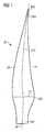
- Figure 1 shows a wind turbine rotor blade 20 which is commonly used with wind turbines.
- the wind turbine rotor blade 20 comprises a root 281, which is surrounded by a root section 282.
- the root section 282 comprises the shape of a hollow circular cylinder. This is advantageous because typically the wind turbine rotor blade 20 is attached to a hub of a wind turbine at the root 281.
- a circular cross section of the root 281 is advantageous.
- the wind turbine rotor blade 20 furthermore comprises a tip 283, which is surrounded by a tip section 284.
- the tip section 284 is the part of the wind turbine rotor blade 20 which is furthest away from the root section 282.
- a shoulder 285 of the wind turbine rotor blade 20 is located between the root section 282 and the tip section 284.
- the shoulder 285 is assigned to the part of the wind turbine rotor blade 20 which has the largest chord length.
- the chord length is defined as the length of a chord line 27, the chord line 27 being perpendicular to the span 273 of the wind turbine rotor blade 20.
- the wind turbine rotor blade 20 comprises a trailing edge 21 and a leading edge 23.
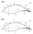
- FIGS 2 and 3 show a wind turbine rotor blade 20 in a cross sectional view.
- An aerodynamic device 30 is connected to the wind turbine rotor blade 20.
- the wind turbine rotor blade 20 and the aerodynamic device 30 both together form an arrangement 10.
- the wind turbine rotor blade 20 comprises a leading edge 23 and a trailing edge 21.
- the leading edge 23 is connected by a straight line with the trailing edge 21.
- the straight line is referred to as the chord line 27.
- the wind turbine rotor blade 20 furthermore comprises a leading edge section 24 which is delimited by a line perpendicular to the chord line 27 at a chordwise position of 20% chord length 271, as seen from the leading edge 23.
- a trailing edge section 22 is defined and delimited by a line 272 which is perpendicular to the chord line 27 at a chordwise position of 80% chord length 272, as seen from the leading edge 23.
- the part between the leading edge 23 and the trailing edge 21 substantially above the chord line 27 is referred to as the suction side 25 of the wind turbine rotor blade 20, while the part between the leading edge 23 and the trailing edge 21 substantially below the chord length 27 is referred to as the pressure side 26.
- the aerodynamic device 30 is connected to the trailing edge section 22 once directly and secondly via a buckling element 31.
- Figure 3 shows a scenario where the buckling element 31 is deformed considerably due to an extreme load applied on the buckling element 31 in a direction substantially perpendicular to the chord line 27.
- the deformation of the buckling element 31 results in a deflection of the wind flow 11 flowing from the leading edge section 24 to the trailing edge section 22.
- the deflection of the wind flow 11 is such that it exits the trailing edge section 22 not towards the pressure side 26 of the wind turbine rotor blade 20 but towards the suction side 25 of the wind turbine rotor blade 20.
- Figure 4 illustrates an exemplary position of the first and second portion of the aerodynamic device 301, 302 and the first and the second portion of the wind turbine rotor blade 201, 202.
- the wind turbine rotor blade 20 comprises a first portion 201 which is arranged and prepared to be connected to a first portion of the aerodynamic device 301.
- the wind turbine rotor blade 20 comprises a second portion 202 which is arranged and prepared to be connected to the buckling element 31 which itself is connected to a second portion of the aerodynamic device 302.
- the first portion of the wind turbine rotor blade 201 and the first portion of the aerodynamic device 301 are connected they form a direct connection.
- the second portion of the wind turbine rotor blade 202 and the second portion of the aerodynamic device 302 are connected they are indirectly connected with each other, namely via the buckling element 31.
- the buckling element 31 is in principle deformable, in particular for loads above the stability limit 43, the aerodynamic device 30 can be seen as being attached to the wind turbine rotor blade 20 in a flexible manner. If the stability limit 43 is set wisely, the flexible arrangement of the aerodynamic device 30 with regard to the wind turbine rotor blade 20 can be exploited in order to efficiently manipulate the load acting on the wind turbine rotor blade 20, and even the wind turbine as a whole.
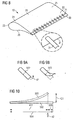
- FIG. 5 shows an exemplary design of an aerodynamic device 30 and a buckling element 31.
- the buckling element 31 is made of thin plastics material.
- the first portion of the aerodynamic device 301 which is arranged and prepared for being connected to a first portion of a wind turbine rotor blade 201 (not shown), can be seen.
- a compressive force 41 acting in parallel to the longitudinal dimension of the buckling element 31 is shown.
- the compressive force 41 exceeds the stability limit 43 of the buckling element, thus the buckling element 31 deforms significantly.
- the un-deformed aerodynamic device 501 is shown in dashed lines.
- Figure 6 shows a buckling element 31, once in an un-deformed state 502, and once in a deformed state 503 due to compressive force 41 acting along the longitudinal dimension of the buckling element 31.
- the deformation of the buckling element 31 can be characterized by a deformation parallel to the compressive force 411 and a deformation perpendicular to the compressive force 412. Note that the total extension of the buckling element 31 parallel to the compressive force 41 in the un-deformed state 504 decreases by the amount 505.
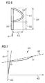
- FIG. 7 shows an exemplary load-deformation curve 403 of a buckling element 31.
- the load-deformation curve 403 shows the load 401 acting on the buckling element 31, and the resulting deformation 402. It can be seen that for loads up to a stability limit 43 the resulting deformation 402 is relatively small. As a consequence, the slope of the load-deformation curve 403 up to the stability limit 43 is large. At the stability limit 43 the slope of the load-deformation curve 403 changes abruptly. In the example shown in Figure 7 , the slope of the load-deformation curve 403 is significantly smaller in the section between the stability limit 43 and an elastic limit 44. Note that the section up to the stability limit 43 is also referred to as the first section and the section between the stability limit 43 and the elastic limit 44 is also referred to as the second section.
- the slope is varying in the second section of the exemplary load-deformation curve 403 of Figure 7 .
- the average slopes 505, 506 of the load-deformation curve 403 in the first and second section, respectively are compared. It can be seen, that in Figure 7 , the average slope of the second section 506 is at least three times greater than the average slope of the first section 505.
- the stability limit 43 is also referred to as a buckling instability. Descriptively speaking, the buckling element 43 does not experience much deformation 402 for loads 401 up to the stability limit 43; however, for loads exceeding the stability limit 43 this changes abruptly and small incremental loads lead to relatively large incremental deformation.
- Figure 8 shows another embodiment of an arrangement 10, comprising a wind turbine rotor blade 20 and an aerodynamic device 30, both items 20, 30 being attached to each other by means of a set of buckling elements 31.
- the buckling elements 31 are made of thin plastics material.
- the wind turbine rotor blade 20 comprises a suction side 25, a pressure side 26, a leading edge 23 and a trailing edge 21.
- the trailing edge 21 has the shape of a flat back.
- the aerodynamic device 30 effectively prolongs the chord length of the chord lines 27 (not shown), at least during the un-deformed state of the buckling elements 31 as shown in Figure 8 .
- Each buckling element 31 of the set of buckling elements 31 is shaped as a slightly curved strip. The slight curvature gives additional stability to the buckling element 31.
- Figure 9a illustrates the buckling element 31 as such in a un-deformed state 502. It can be seen that it is arranged and prepared that a bending moment 42 acts on one of the ends of the buckling element 31.
- Figure 9b shows the same buckling element 31 as in Figure 9a in a deformed state 503.
- the influence of the bending moment 42 acting on the buckling element 31 can well be seen.
- the impact of a set of deformed buckling elements 31 on the arrangement as shown in Figure 8 can well be imagined: The aerodynamic device 30 would snap towards the suction side 25 and thus the wind flow characteristics, in particular at the trailing edge section 22, changes significantly.
- Figure 10 shows a comparison between a buckling element in a un-deformed state 502 and a deformed state 503. It can be seen, that the deformation shown in Figure 10 is due to a bending moment 42, which acts perpendicularly to the main extension of the buckling element 31.
- the deformation of the buckling element 31 can be characterized by a deformation parallel to the bending moment 421 and a deformation perpendicular to the bending moment 422. Note that the total extension of the buckling element 31 parallel to the bending moment 42 in the un-deformed state 604 decreases by the amount 605.
Landscapes
- Engineering & Computer Science (AREA)
- Life Sciences & Earth Sciences (AREA)
- Sustainable Development (AREA)
- Sustainable Energy (AREA)
- Chemical & Material Sciences (AREA)
- Combustion & Propulsion (AREA)
- Mechanical Engineering (AREA)
- General Engineering & Computer Science (AREA)
- Physics & Mathematics (AREA)
- Fluid Mechanics (AREA)
- Wind Motors (AREA)
Claims (14)
- Anordnung (10), die ein Windturbinenrotorblatt (20) und eine aerodynamische Vorrichtung (30) umfasst,
wobei- das Windturbinenrotorblatt (20) eine Hinterkante (21) umfasst, die durch ein Hinterkantenteil (22) eingefasst ist,- die aerodynamische Vorrichtung (30) ein Knickelement (31) umfasst,- die aerodynamische Vorrichtung (30) eine Klappe umfasst,- das Knickelement (31) eine Stabilitätsgrenze (43) und eine Elastizitätsgrenze (44) aufweist, wobei die Stabilitätsgrenze (43) unter der Elastizitätsgrenze (44) liegt,- das Knickelement (31) so konfiguriert ist, dass es sich elastisch verformt, wenn eine Last darauf einwirkt, die unter der Elastizitätsgrenze (44) liegt, und- sich das Knickelement (31) plötzlich verformt, wenn eine Last darauf einwirkt, die in etwa der Höhe der Stabilitätsgrenze (43) entspricht, so dass sich die aerodynamischen Eigenschaften der Anordnung (10) ändern und eine Belastung des Windturbinenrotorblatts (20) passiv vermindert wird,- dadurch gekennzeichnet, dass die aerodynamische Vorrichtung (30) am Hinterkantenteil (22) an dem Windturbinenrotorblatt (20) angebracht ist. - Anordnung (10) nach Anspruch 1,
bei der das Verhältnis der auf das Knickelement (31) einwirkenden Last und seiner Verformung (411, 412, 421, 422) für Lasten, die unter der Stabilitätsgrenze (43) liegen, im Wesentlichen konstant ist. - Anordnung (10) nach einem der vorhergehenden Ansprüche,
bei der das durchschnittliche Verhältnis der auf das Knickelement (31) einwirkenden Last und seiner Verformung (411, 412, 421, 422) für zwischen der Stabilitätsgrenze (43) und der Elastizitätsgrenze (44) liegende Lasten im Vergleich zum durchschnittlichen Verhältnis der auf das Knickelement (31) einwirkenden Last und seiner Verformung (411, 412, 421, 422) für unter der Stabilitätsgrenze (43) liegende Lasten geringer ist. - Anordnung (10) nach einem der vorhergehenden Ansprüche, wobei- eine Last-Verformungskurve (403), die durch die auf das Knickelement (31) einwirkende Last und seine Verformung (411, 412, 421, 422) definiert wird, einen ersten Teil für Lasten, die unter der Stabilitätsgrenze (43) liegen, und einen zweiten Teil für Lasten umfasst, die zwischen der Stabilitätsgrenze (43) und der Elastizitätsgrenze (44) liegen, und- die durchschnittliche Steigung der Last-Verformungskurve (403) im ersten Teil größer ist als im zweiten Teil.
- Anordnung (10) nach Anspruch 4,
wobei die durchschnittliche Steigung der Last-Verformungskurve (403) im ersten Teil mindestens dreimal, insbesondere mindestens fünfmal größer ist als im zweiten Teil. - Anordnung (10) nach einem der vorhergehenden Ansprüche,
bei der das Knickelement (31) so konfiguriert ist, dass die Höhe der Stabilitätsgrenze (43) so angepasst ist, dass eine Verminderung der Belastung des Windturbinenrotorblatts (20) bei extremen Lasten am Windturbinenrotorblatt (20), insbesondere extremen Windlasten und/oder Windböen, erreicht wird. - Anordnung (10) nach einem der vorhergehenden Ansprüche,
bei der die aerodynamische Vorrichtung (30) eine gezackte Platte umfasst. - Anordnung (10) nach einem der vorhergehenden Ansprüche, bei der- das Windturbinenrotorblatt (20) eine Spitze (283) und eine Wurzel (281) umfasst und- die aerodynamische Vorrichtung (30) in der Nähe der Spitze (283) an dem Windturbinenrotorblatt (20) angebracht ist.
- Anordnung (10) nach einem der vorhergehenden Ansprüche, bei der- das Windturbinenrotorblatt (20) eine Saugseite (25) und eine Druckseite (26) umfasst und- das Knickelement (31) bei einer die Stabilitätsgrenze (43) überschreitenden Last so ausgelenkt wird, dass eine Windströmung (11) von einer Vorderkante (23) des Windturbinenrotorblatts (20) entlang der Druckseite (26) zum Hinterkantenteil (22) zur Saugseite (26) abgelenkt wird, wodurch sich der aerodynamische Auftrieb des Windturbinenrotorblatts (20) verringert.
- Anordnung (10) nach einem der vorhergehenden Ansprüche,
bei der die aerodynamische Vorrichtung (30) eine Profilsehne (27) des Windturbinenrotorblatts (20) verlängert. - Anordnung (10) nach einem der vorhergehenden Ansprüche,
bei der die auf das Knickelement (31) einwirkende Last hauptsächlich auf eine Druckkraft (41) zurückzuführen ist, die im Wesentlichen parallel zur Richtung der größten Abmessung des Knickelements (31) gerichtet ist. - Anordnung (10) nach einem der vorhergehenden Ansprüche,
bei der- ein erster Abschnitt der aerodynamischen Vorrichtung (301) direkt mit einem ersten Abschnitt des Windturbinenrotorblatts (201) verbunden ist,- ein zweiter Abschnitt der aerodynamischen Vorrichtung (302) über das Knickelement (31) mit einem zweiten Abschnitt des Windturbinenrotorblatts (202) verbunden ist und- sich der Abstand zwischen dem zweiten Abschnitt der aerodynamischen Vorrichtung (302) und dem zweiten Abschnitt des Windturbinenrotorblatts (202) plötzlich verringert, wenn eine Last auf das Knickelement (31) einwirkt, die in etwa der Höhe der Stabilitätsgrenze (43) entspricht. - Anordnung (10) nach einem der Ansprüche 1 bis 10,
bei der die auf das Knickelement (31) einwirkende Last ein Biegemoment (42) verursacht, das im Wesentlichen senkrecht zur Richtung der größten Abmessung des Knickelements (31) gerichtet ist. - Verwendung eines Knickelements (31) zum passiven Vermindern einer Belastung eines Windturbinenrotorblatts (20), wobei- das Windturbinenrotorblatt (20) eine Hinterkante (21) umfasst, die durch ein Hinterkantenteil (22) eingefasst ist,- das Knickelement (31) zumindest ein Bestandteil einer aerodynamischen Vorrichtung (30) ist, die eine Klappe umfasst,- das Knickelement (31) eine Stabilitätsgrenze (43) und eine Elastizitätsgrenze (44) aufweist, wobei die Stabilitätsgrenze (43) geringer ist als die Elastizitätsgrenze (44),- das Knickelement (31) so konfiguriert ist, dass es sich elastisch verformt, wenn eine Last darauf einwirkt, die unter der Elastizitätsgrenze (43) liegt, und- sich das Knickelement (31) plötzlich verformt, wenn eine Last darauf einwirkt, die in etwa dem Maß der Stabilitätsgrenze (43) entspricht,- dadurch gekennzeichnet, dass die aerodynamische Vorrichtung (30) zum Anbringen am Hinterkantenteil (22) an dem Windturbinenrotorblatt (20) angeordnet und ausgelegt ist.
Priority Applications (5)
| Application Number | Priority Date | Filing Date | Title |
|---|---|---|---|
| DK14154895.8T DK2908001T3 (da) | 2014-02-12 | 2014-02-12 | Midler til dæmpning af belastning på en vindmøllerotorvinge |
| EP14154895.8A EP2908001B1 (de) | 2014-02-12 | 2014-02-12 | Mittel zur Verminderung der Belastung eines Windturbinenrotorblatts |
| CN201580008481.3A CN105980701B (zh) | 2014-02-12 | 2015-01-22 | 用于减轻风力涡轮机的转子叶片上的应变的装置 |
| PCT/EP2015/051259 WO2015121044A1 (en) | 2014-02-12 | 2015-01-22 | Means for alleviating strain on a wind turbine rotor blade |
| US15/101,043 US10247169B2 (en) | 2014-02-12 | 2015-01-22 | Means for alleviating strain on a wind turbine rotor blade |
Applications Claiming Priority (1)
| Application Number | Priority Date | Filing Date | Title |
|---|---|---|---|
| EP14154895.8A EP2908001B1 (de) | 2014-02-12 | 2014-02-12 | Mittel zur Verminderung der Belastung eines Windturbinenrotorblatts |
Publications (2)
| Publication Number | Publication Date |
|---|---|
| EP2908001A1 EP2908001A1 (de) | 2015-08-19 |
| EP2908001B1 true EP2908001B1 (de) | 2016-09-21 |
Family
ID=50073016
Family Applications (1)
| Application Number | Title | Priority Date | Filing Date |
|---|---|---|---|
| EP14154895.8A Not-in-force EP2908001B1 (de) | 2014-02-12 | 2014-02-12 | Mittel zur Verminderung der Belastung eines Windturbinenrotorblatts |
Country Status (5)
| Country | Link |
|---|---|
| US (1) | US10247169B2 (de) |
| EP (1) | EP2908001B1 (de) |
| CN (1) | CN105980701B (de) |
| DK (1) | DK2908001T3 (de) |
| WO (1) | WO2015121044A1 (de) |
Families Citing this family (16)
| Publication number | Priority date | Publication date | Assignee | Title |
|---|---|---|---|---|
| DE202015000665U1 (de) * | 2015-01-24 | 2015-06-26 | Dieter Röhm | Vorrichtung eines Sicherheitssystems und/oder Ressourcen-/Energieeffizienz-Verbesserungs - Systems zur Stömungsbeeinflussung eines Aero- oder Hydrodynamischen Körpers (3), nach dem Prinzip einer Rückstromklappe (4) |
| WO2017180192A1 (en) * | 2016-04-15 | 2017-10-19 | Siemens Aktiengesellschaft | Rotor blade with a serrated trailing edge |
| EP3096003B1 (de) * | 2015-05-21 | 2021-03-17 | Siemens Gamesa Renewable Energy A/S | Rotorblatt mit verzahnungen für windkraftanlage |
| US10400744B2 (en) | 2016-04-28 | 2019-09-03 | General Electric Company | Wind turbine blade with noise reducing micro boundary layer energizers |
| DK179306B1 (en) * | 2016-09-27 | 2018-04-23 | Envision Energy Denmark Aps | Wind turbine and method for controlling buckling in a wind turbine blade |
| US10612517B2 (en) * | 2017-03-09 | 2020-04-07 | General Electric Company | Flexible extension for wind turbine rotor blades |
| US11674497B2 (en) * | 2017-08-23 | 2023-06-13 | Lm Wind Power International Technology Ii Aps | Wind turbine blade and a method of operating such a wind turbine blade |
| DK3587798T3 (da) * | 2018-06-27 | 2020-11-23 | Siemens Gamesa Renewable Energy As | Aerodynamisk konstruktion |
| EP3587799A1 (de) * | 2018-06-27 | 2020-01-01 | Siemens Gamesa Renewable Energy A/S | Aerodynamische struktur |
| CN108678898A (zh) * | 2018-07-19 | 2018-10-19 | 宁波启泷能源技术有限公司 | 一种利用气流冲击张力推动叶轮旋转的风力发电机叶片 |
| DE102018127367A1 (de) * | 2018-11-02 | 2020-05-07 | Wobben Properties Gmbh | Rotorblatt für eine Windenergieanlage und Windenergieanlage |
| EP3667061A1 (de) * | 2018-12-13 | 2020-06-17 | Siemens Gamesa Renewable Energy A/S | Anpassbarer spoiler für ein windturbinenrotorblatt |
| CN111379662A (zh) * | 2018-12-29 | 2020-07-07 | 中材科技风电叶片股份有限公司 | 风电叶片及风机 |
| CN114096750A (zh) * | 2019-05-08 | 2022-02-25 | 维斯塔斯风力系统有限公司 | 构造成降低后缘噪声的风力涡轮机转子叶片 |
| EP3978748A1 (de) * | 2020-10-01 | 2022-04-06 | Siemens Gamesa Renewable Energy A/S | Windturbinenkomponente, windturbine und verfahren zur herstellung einer windturbinenkomponente |
| GB2600130A (en) * | 2020-10-22 | 2022-04-27 | Airbus Operations Ltd | Flow control device |
Family Cites Families (14)
| Publication number | Priority date | Publication date | Assignee | Title |
|---|---|---|---|---|
| EP1350027B1 (de) * | 2000-12-23 | 2012-11-07 | Aloys Wobben | Rotorblatt für eine windenergieanlage |
| US7413408B1 (en) * | 2007-02-22 | 2008-08-19 | Samuel B Tafoya | Vibration-reducing and noise-reducing spoiler for helicopter rotors, aircraft wings, propellers, and turbine blades |
| US8418967B2 (en) * | 2008-02-21 | 2013-04-16 | Cornerstone Research Group, Inc. | Passive adaptive structures |
| WO2009137143A1 (en) * | 2008-02-21 | 2009-11-12 | Cornerstone Research Group, Inc. | Passive adaptive structures |
| DK200900420A (en) | 2009-03-26 | 2010-09-27 | Vestas Wind Sys As | A wind turbine blade comprising a trailing edge flap and a piezoelectric actuator |
| GB2475694A (en) | 2009-11-25 | 2011-06-01 | Vestas Wind Sys As | Flap control for wind turbine blades |
| EP2526287B1 (de) * | 2010-01-21 | 2016-07-06 | Vestas Wind Systems A/S | Windturbinenrotorblatt mit knickaustrittskante |
| US8083488B2 (en) * | 2010-08-23 | 2011-12-27 | General Electric Company | Blade extension for rotor blade in wind turbine |
| EP2423104A1 (de) * | 2010-08-27 | 2012-02-29 | Cornerstone Research Group, Inc. | Passiv anpassbare Strukturen |
| EP2783103B1 (de) * | 2011-11-23 | 2017-01-04 | LM WP Patent Holding A/S | Windturbinenblatt |
| EP2647835B1 (de) * | 2012-04-04 | 2016-11-16 | Siemens Aktiengesellschaft | Flexible Klappenanordnung für ein Rottorblatt |
| US9458821B2 (en) * | 2012-09-11 | 2016-10-04 | General Electric Company | Attachment system for a wind turbine rotor blade accessory |
| GB201217212D0 (en) | 2012-09-26 | 2012-11-07 | Blade Dynamics Ltd | Windturbine blade |
| US9803617B2 (en) * | 2014-06-18 | 2017-10-31 | General Electric Company | Method and system for tensioning tension fabrics in wind-turbine |
-
2014
- 2014-02-12 EP EP14154895.8A patent/EP2908001B1/de not_active Not-in-force
- 2014-02-12 DK DK14154895.8T patent/DK2908001T3/da active
-
2015
- 2015-01-22 WO PCT/EP2015/051259 patent/WO2015121044A1/en active Application Filing
- 2015-01-22 CN CN201580008481.3A patent/CN105980701B/zh not_active Expired - Fee Related
- 2015-01-22 US US15/101,043 patent/US10247169B2/en not_active Expired - Fee Related
Also Published As
| Publication number | Publication date |
|---|---|
| WO2015121044A1 (en) | 2015-08-20 |
| DK2908001T3 (da) | 2017-01-02 |
| US10247169B2 (en) | 2019-04-02 |
| US20160369775A1 (en) | 2016-12-22 |
| CN105980701A (zh) | 2016-09-28 |
| EP2908001A1 (de) | 2015-08-19 |
| CN105980701B (zh) | 2019-09-20 |
Similar Documents
| Publication | Publication Date | Title |
|---|---|---|
| EP2908001B1 (de) | Mittel zur Verminderung der Belastung eines Windturbinenrotorblatts | |
| US10451037B2 (en) | Wind turbine blade | |
| EP2034178B1 (de) | Windturbinenschaufel mit lenkbaren Blättern | |
| EP2019203B2 (de) | Rotorblatt einer Windenergieanlage mit gewölbten Klappen | |
| EP2808541A2 (de) | Windturbinenschaufel mit einer Versteifung auf Zug zur passiven Steuerung einer Klappenbewegung | |
| EP2998571B1 (de) | Aufzugbeeinflussungsvorrichtung für ein Rotorblatt einer Windenergieanlage | |
| US9759191B2 (en) | Wind turbine blade | |
| EP2940293A1 (de) | Aerodynamische vorrichtung eines rotorblatts einer windturbine | |
| EP2085609B1 (de) | Windturbinenschaufel mit Biegklappen, die von Oberflächendruckänderungen gesteuert werden | |
| EP2937558B1 (de) | Luftstromablenkvorrichtung einer Windturbine und Verfahren | |
| EP2899395B1 (de) | Windturbinenschaufeln | |
| EP2664791A2 (de) | Windturbinenschaufel mit veränderlicher Geometrie mit passiver Steuerung | |
| EP3146201A1 (de) | Aerodynamische vorrichtung einer rotorschaufel einer windturbine | |
| US10422318B2 (en) | Wind turbine blade | |
| EP3176425A1 (de) | Anordnung von tragflügelförmigem körper und lärmverringernder umzahnung und damit ausgestattete windturbine | |
| EP2535269B1 (de) | Rotorblatt mit aktiver Klappe |
Legal Events
| Date | Code | Title | Description |
|---|---|---|---|
| PUAI | Public reference made under article 153(3) epc to a published international application that has entered the european phase |
Free format text: ORIGINAL CODE: 0009012 |
|
| 17P | Request for examination filed |
Effective date: 20150407 |
|
| AK | Designated contracting states |
Kind code of ref document: A1 Designated state(s): AL AT BE BG CH CY CZ DE DK EE ES FI FR GB GR HR HU IE IS IT LI LT LU LV MC MK MT NL NO PL PT RO RS SE SI SK SM TR |
|
| AX | Request for extension of the european patent |
Extension state: BA ME |
|
| 17Q | First examination report despatched |
Effective date: 20150821 |
|
| GRAP | Despatch of communication of intention to grant a patent |
Free format text: ORIGINAL CODE: EPIDOSNIGR1 |
|
| INTG | Intention to grant announced |
Effective date: 20160406 |
|
| GRAS | Grant fee paid |
Free format text: ORIGINAL CODE: EPIDOSNIGR3 |
|
| GRAA | (expected) grant |
Free format text: ORIGINAL CODE: 0009210 |
|
| AK | Designated contracting states |
Kind code of ref document: B1 Designated state(s): AL AT BE BG CH CY CZ DE DK EE ES FI FR GB GR HR HU IE IS IT LI LT LU LV MC MK MT NL NO PL PT RO RS SE SI SK SM TR |
|
| REG | Reference to a national code |
Ref country code: GB Ref legal event code: FG4D |
|
| REG | Reference to a national code |
Ref country code: CH Ref legal event code: EP |
|
| REG | Reference to a national code |
Ref country code: AT Ref legal event code: REF Ref document number: 831273 Country of ref document: AT Kind code of ref document: T Effective date: 20161015 |
|
| REG | Reference to a national code |
Ref country code: IE Ref legal event code: FG4D |
|
| REG | Reference to a national code |
Ref country code: DE Ref legal event code: R096 Ref document number: 602014003710 Country of ref document: DE |
|
| REG | Reference to a national code |
Ref country code: DK Ref legal event code: T3 Effective date: 20161227 |
|
| REG | Reference to a national code |
Ref country code: NL Ref legal event code: MP Effective date: 20160921 Ref country code: LT Ref legal event code: MG4D |
|
| PG25 | Lapsed in a contracting state [announced via postgrant information from national office to epo] |
Ref country code: LT Free format text: LAPSE BECAUSE OF FAILURE TO SUBMIT A TRANSLATION OF THE DESCRIPTION OR TO PAY THE FEE WITHIN THE PRESCRIBED TIME-LIMIT Effective date: 20160921 Ref country code: FI Free format text: LAPSE BECAUSE OF FAILURE TO SUBMIT A TRANSLATION OF THE DESCRIPTION OR TO PAY THE FEE WITHIN THE PRESCRIBED TIME-LIMIT Effective date: 20160921 Ref country code: RS Free format text: LAPSE BECAUSE OF FAILURE TO SUBMIT A TRANSLATION OF THE DESCRIPTION OR TO PAY THE FEE WITHIN THE PRESCRIBED TIME-LIMIT Effective date: 20160921 Ref country code: NO Free format text: LAPSE BECAUSE OF FAILURE TO SUBMIT A TRANSLATION OF THE DESCRIPTION OR TO PAY THE FEE WITHIN THE PRESCRIBED TIME-LIMIT Effective date: 20161221 |
|
| REG | Reference to a national code |
Ref country code: AT Ref legal event code: MK05 Ref document number: 831273 Country of ref document: AT Kind code of ref document: T Effective date: 20160921 |
|
| PG25 | Lapsed in a contracting state [announced via postgrant information from national office to epo] |
Ref country code: NL Free format text: LAPSE BECAUSE OF FAILURE TO SUBMIT A TRANSLATION OF THE DESCRIPTION OR TO PAY THE FEE WITHIN THE PRESCRIBED TIME-LIMIT Effective date: 20160921 Ref country code: SE Free format text: LAPSE BECAUSE OF FAILURE TO SUBMIT A TRANSLATION OF THE DESCRIPTION OR TO PAY THE FEE WITHIN THE PRESCRIBED TIME-LIMIT Effective date: 20160921 Ref country code: GR Free format text: LAPSE BECAUSE OF FAILURE TO SUBMIT A TRANSLATION OF THE DESCRIPTION OR TO PAY THE FEE WITHIN THE PRESCRIBED TIME-LIMIT Effective date: 20161222 Ref country code: LV Free format text: LAPSE BECAUSE OF FAILURE TO SUBMIT A TRANSLATION OF THE DESCRIPTION OR TO PAY THE FEE WITHIN THE PRESCRIBED TIME-LIMIT Effective date: 20160921 |
|
| PG25 | Lapsed in a contracting state [announced via postgrant information from national office to epo] |
Ref country code: RO Free format text: LAPSE BECAUSE OF FAILURE TO SUBMIT A TRANSLATION OF THE DESCRIPTION OR TO PAY THE FEE WITHIN THE PRESCRIBED TIME-LIMIT Effective date: 20160921 Ref country code: EE Free format text: LAPSE BECAUSE OF FAILURE TO SUBMIT A TRANSLATION OF THE DESCRIPTION OR TO PAY THE FEE WITHIN THE PRESCRIBED TIME-LIMIT Effective date: 20160921 |
|
| PG25 | Lapsed in a contracting state [announced via postgrant information from national office to epo] |
Ref country code: BE Free format text: LAPSE BECAUSE OF FAILURE TO SUBMIT A TRANSLATION OF THE DESCRIPTION OR TO PAY THE FEE WITHIN THE PRESCRIBED TIME-LIMIT Effective date: 20160921 Ref country code: SM Free format text: LAPSE BECAUSE OF FAILURE TO SUBMIT A TRANSLATION OF THE DESCRIPTION OR TO PAY THE FEE WITHIN THE PRESCRIBED TIME-LIMIT Effective date: 20160921 Ref country code: IS Free format text: LAPSE BECAUSE OF FAILURE TO SUBMIT A TRANSLATION OF THE DESCRIPTION OR TO PAY THE FEE WITHIN THE PRESCRIBED TIME-LIMIT Effective date: 20170121 Ref country code: SK Free format text: LAPSE BECAUSE OF FAILURE TO SUBMIT A TRANSLATION OF THE DESCRIPTION OR TO PAY THE FEE WITHIN THE PRESCRIBED TIME-LIMIT Effective date: 20160921 Ref country code: BG Free format text: LAPSE BECAUSE OF FAILURE TO SUBMIT A TRANSLATION OF THE DESCRIPTION OR TO PAY THE FEE WITHIN THE PRESCRIBED TIME-LIMIT Effective date: 20161221 Ref country code: CZ Free format text: LAPSE BECAUSE OF FAILURE TO SUBMIT A TRANSLATION OF THE DESCRIPTION OR TO PAY THE FEE WITHIN THE PRESCRIBED TIME-LIMIT Effective date: 20160921 Ref country code: ES Free format text: LAPSE BECAUSE OF FAILURE TO SUBMIT A TRANSLATION OF THE DESCRIPTION OR TO PAY THE FEE WITHIN THE PRESCRIBED TIME-LIMIT Effective date: 20160921 Ref country code: PT Free format text: LAPSE BECAUSE OF FAILURE TO SUBMIT A TRANSLATION OF THE DESCRIPTION OR TO PAY THE FEE WITHIN THE PRESCRIBED TIME-LIMIT Effective date: 20170123 Ref country code: PL Free format text: LAPSE BECAUSE OF FAILURE TO SUBMIT A TRANSLATION OF THE DESCRIPTION OR TO PAY THE FEE WITHIN THE PRESCRIBED TIME-LIMIT Effective date: 20160921 Ref country code: AT Free format text: LAPSE BECAUSE OF FAILURE TO SUBMIT A TRANSLATION OF THE DESCRIPTION OR TO PAY THE FEE WITHIN THE PRESCRIBED TIME-LIMIT Effective date: 20160921 |
|
| REG | Reference to a national code |
Ref country code: DE Ref legal event code: R097 Ref document number: 602014003710 Country of ref document: DE |
|
| PG25 | Lapsed in a contracting state [announced via postgrant information from national office to epo] |
Ref country code: IT Free format text: LAPSE BECAUSE OF FAILURE TO SUBMIT A TRANSLATION OF THE DESCRIPTION OR TO PAY THE FEE WITHIN THE PRESCRIBED TIME-LIMIT Effective date: 20160921 |
|
| PLBE | No opposition filed within time limit |
Free format text: ORIGINAL CODE: 0009261 |
|
| STAA | Information on the status of an ep patent application or granted ep patent |
Free format text: STATUS: NO OPPOSITION FILED WITHIN TIME LIMIT |
|
| 26N | No opposition filed |
Effective date: 20170622 |
|
| PG25 | Lapsed in a contracting state [announced via postgrant information from national office to epo] |
Ref country code: MC Free format text: LAPSE BECAUSE OF FAILURE TO SUBMIT A TRANSLATION OF THE DESCRIPTION OR TO PAY THE FEE WITHIN THE PRESCRIBED TIME-LIMIT Effective date: 20160921 |
|
| REG | Reference to a national code |
Ref country code: CH Ref legal event code: PL |
|
| PG25 | Lapsed in a contracting state [announced via postgrant information from national office to epo] |
Ref country code: LI Free format text: LAPSE BECAUSE OF NON-PAYMENT OF DUE FEES Effective date: 20170228 Ref country code: CH Free format text: LAPSE BECAUSE OF NON-PAYMENT OF DUE FEES Effective date: 20170228 |
|
| PG25 | Lapsed in a contracting state [announced via postgrant information from national office to epo] |
Ref country code: SI Free format text: LAPSE BECAUSE OF FAILURE TO SUBMIT A TRANSLATION OF THE DESCRIPTION OR TO PAY THE FEE WITHIN THE PRESCRIBED TIME-LIMIT Effective date: 20160921 |
|
| REG | Reference to a national code |
Ref country code: FR Ref legal event code: ST Effective date: 20171031 |
|
| PG25 | Lapsed in a contracting state [announced via postgrant information from national office to epo] |
Ref country code: LU Free format text: LAPSE BECAUSE OF NON-PAYMENT OF DUE FEES Effective date: 20170212 |
|
| PG25 | Lapsed in a contracting state [announced via postgrant information from national office to epo] |
Ref country code: FR Free format text: LAPSE BECAUSE OF NON-PAYMENT OF DUE FEES Effective date: 20170228 |
|
| PG25 | Lapsed in a contracting state [announced via postgrant information from national office to epo] |
Ref country code: MT Free format text: LAPSE BECAUSE OF NON-PAYMENT OF DUE FEES Effective date: 20170212 |
|
| PG25 | Lapsed in a contracting state [announced via postgrant information from national office to epo] |
Ref country code: AL Free format text: LAPSE BECAUSE OF FAILURE TO SUBMIT A TRANSLATION OF THE DESCRIPTION OR TO PAY THE FEE WITHIN THE PRESCRIBED TIME-LIMIT Effective date: 20160921 |
|
| REG | Reference to a national code |
Ref country code: IE Ref legal event code: MM4A |
|
| PG25 | Lapsed in a contracting state [announced via postgrant information from national office to epo] |
Ref country code: IE Free format text: LAPSE BECAUSE OF NON-PAYMENT OF DUE FEES Effective date: 20170212 |
|
| PG25 | Lapsed in a contracting state [announced via postgrant information from national office to epo] |
Ref country code: HU Free format text: LAPSE BECAUSE OF FAILURE TO SUBMIT A TRANSLATION OF THE DESCRIPTION OR TO PAY THE FEE WITHIN THE PRESCRIBED TIME-LIMIT; INVALID AB INITIO Effective date: 20140212 |
|
| REG | Reference to a national code |
Ref country code: DE Ref legal event code: R081 Ref document number: 602014003710 Country of ref document: DE Owner name: SIEMENS GAMESA RENEWABLE ENERGY A/S, DK Free format text: FORMER OWNER: SIEMENS AKTIENGESELLSCHAFT, 80333 MUENCHEN, DE |
|
| PG25 | Lapsed in a contracting state [announced via postgrant information from national office to epo] |
Ref country code: CY Free format text: LAPSE BECAUSE OF FAILURE TO SUBMIT A TRANSLATION OF THE DESCRIPTION OR TO PAY THE FEE WITHIN THE PRESCRIBED TIME-LIMIT Effective date: 20160921 |
|
| PG25 | Lapsed in a contracting state [announced via postgrant information from national office to epo] |
Ref country code: MK Free format text: LAPSE BECAUSE OF FAILURE TO SUBMIT A TRANSLATION OF THE DESCRIPTION OR TO PAY THE FEE WITHIN THE PRESCRIBED TIME-LIMIT Effective date: 20160921 |
|
| REG | Reference to a national code |
Ref country code: GB Ref legal event code: 732E Free format text: REGISTERED BETWEEN 20191128 AND 20191204 |
|
| PG25 | Lapsed in a contracting state [announced via postgrant information from national office to epo] |
Ref country code: TR Free format text: LAPSE BECAUSE OF FAILURE TO SUBMIT A TRANSLATION OF THE DESCRIPTION OR TO PAY THE FEE WITHIN THE PRESCRIBED TIME-LIMIT Effective date: 20160921 |
|
| PGFP | Annual fee paid to national office [announced via postgrant information from national office to epo] |
Ref country code: GB Payment date: 20200206 Year of fee payment: 7 Ref country code: DK Payment date: 20200224 Year of fee payment: 7 |
|
| PG25 | Lapsed in a contracting state [announced via postgrant information from national office to epo] |
Ref country code: HR Free format text: LAPSE BECAUSE OF FAILURE TO SUBMIT A TRANSLATION OF THE DESCRIPTION OR TO PAY THE FEE WITHIN THE PRESCRIBED TIME-LIMIT Effective date: 20160921 |
|
| PGFP | Annual fee paid to national office [announced via postgrant information from national office to epo] |
Ref country code: DE Payment date: 20200420 Year of fee payment: 7 |
|
| REG | Reference to a national code |
Ref country code: DE Ref legal event code: R119 Ref document number: 602014003710 Country of ref document: DE |
|
| REG | Reference to a national code |
Ref country code: DK Ref legal event code: EBP Effective date: 20210228 |
|
| GBPC | Gb: european patent ceased through non-payment of renewal fee |
Effective date: 20210212 |
|
| PG25 | Lapsed in a contracting state [announced via postgrant information from national office to epo] |
Ref country code: DE Free format text: LAPSE BECAUSE OF NON-PAYMENT OF DUE FEES Effective date: 20210901 Ref country code: DK Free format text: LAPSE BECAUSE OF NON-PAYMENT OF DUE FEES Effective date: 20210228 Ref country code: GB Free format text: LAPSE BECAUSE OF NON-PAYMENT OF DUE FEES Effective date: 20210212 |