EP2907727A1 - Device for detecting physical quantities and electromotive power steering device using same - Google Patents
Device for detecting physical quantities and electromotive power steering device using same Download PDFInfo
- Publication number
- EP2907727A1 EP2907727A1 EP13846141.3A EP13846141A EP2907727A1 EP 2907727 A1 EP2907727 A1 EP 2907727A1 EP 13846141 A EP13846141 A EP 13846141A EP 2907727 A1 EP2907727 A1 EP 2907727A1
- Authority
- EP
- European Patent Office
- Prior art keywords
- physical quantity
- signal
- diagnostic
- diagnostic signal
- detecting device
- Prior art date
- Legal status (The legal status is an assumption and is not a legal conclusion. Google has not performed a legal analysis and makes no representation as to the accuracy of the status listed.)
- Granted
Links
- 238000001514 detection method Methods 0.000 claims abstract description 77
- 230000005856 abnormality Effects 0.000 claims abstract description 66
- 230000005540 biological transmission Effects 0.000 claims abstract description 19
- 230000002159 abnormal effect Effects 0.000 claims description 15
- 230000008859 change Effects 0.000 claims description 7
- 230000008054 signal transmission Effects 0.000 abstract description 28
- 238000000034 method Methods 0.000 description 115
- 230000008569 process Effects 0.000 description 108
- 230000007246 mechanism Effects 0.000 description 7
- 238000010586 diagram Methods 0.000 description 6
- 230000007935 neutral effect Effects 0.000 description 4
- 230000000630 rising effect Effects 0.000 description 4
- 238000002405 diagnostic procedure Methods 0.000 description 3
- 230000010354 integration Effects 0.000 description 3
- 238000012544 monitoring process Methods 0.000 description 3
- 238000012545 processing Methods 0.000 description 3
- 238000012360 testing method Methods 0.000 description 3
- 238000012935 Averaging Methods 0.000 description 2
- 238000006073 displacement reaction Methods 0.000 description 2
- 230000005669 field effect Effects 0.000 description 2
- 230000009466 transformation Effects 0.000 description 2
- 238000003745 diagnosis Methods 0.000 description 1
- 230000000694 effects Effects 0.000 description 1
- 239000007788 liquid Substances 0.000 description 1
- 230000004044 response Effects 0.000 description 1
Images





Classifications
-
- B—PERFORMING OPERATIONS; TRANSPORTING
- B62—LAND VEHICLES FOR TRAVELLING OTHERWISE THAN ON RAILS
- B62D—MOTOR VEHICLES; TRAILERS
- B62D5/00—Power-assisted or power-driven steering
- B62D5/04—Power-assisted or power-driven steering electrical, e.g. using an electric servo-motor connected to, or forming part of, the steering gear
- B62D5/0457—Power-assisted or power-driven steering electrical, e.g. using an electric servo-motor connected to, or forming part of, the steering gear characterised by control features of the drive means as such
- B62D5/046—Controlling the motor
- B62D5/0463—Controlling the motor calculating assisting torque from the motor based on driver input
-
- B—PERFORMING OPERATIONS; TRANSPORTING
- B62—LAND VEHICLES FOR TRAVELLING OTHERWISE THAN ON RAILS
- B62D—MOTOR VEHICLES; TRAILERS
- B62D5/00—Power-assisted or power-driven steering
- B62D5/04—Power-assisted or power-driven steering electrical, e.g. using an electric servo-motor connected to, or forming part of, the steering gear
- B62D5/0457—Power-assisted or power-driven steering electrical, e.g. using an electric servo-motor connected to, or forming part of, the steering gear characterised by control features of the drive means as such
- B62D5/0481—Power-assisted or power-driven steering electrical, e.g. using an electric servo-motor connected to, or forming part of, the steering gear characterised by control features of the drive means as such monitoring the steering system, e.g. failures
- B62D5/049—Power-assisted or power-driven steering electrical, e.g. using an electric servo-motor connected to, or forming part of, the steering gear characterised by control features of the drive means as such monitoring the steering system, e.g. failures detecting sensor failures
-
- G—PHYSICS
- G01—MEASURING; TESTING
- G01L—MEASURING FORCE, STRESS, TORQUE, WORK, MECHANICAL POWER, MECHANICAL EFFICIENCY, OR FLUID PRESSURE
- G01L5/00—Apparatus for, or methods of, measuring force, work, mechanical power, or torque, specially adapted for specific purposes
- G01L5/22—Apparatus for, or methods of, measuring force, work, mechanical power, or torque, specially adapted for specific purposes for measuring the force applied to control members, e.g. control members of vehicles, triggers
- G01L5/221—Apparatus for, or methods of, measuring force, work, mechanical power, or torque, specially adapted for specific purposes for measuring the force applied to control members, e.g. control members of vehicles, triggers to steering wheels, e.g. for power assisted steering
-
- G—PHYSICS
- G08—SIGNALLING
- G08C—TRANSMISSION SYSTEMS FOR MEASURED VALUES, CONTROL OR SIMILAR SIGNALS
- G08C25/00—Arrangements for preventing or correcting errors; Monitoring arrangements
-
- H—ELECTRICITY
- H04—ELECTRIC COMMUNICATION TECHNIQUE
- H04Q—SELECTING
- H04Q9/00—Arrangements in telecontrol or telemetry systems for selectively calling a substation from a main station, in which substation desired apparatus is selected for applying a control signal thereto or for obtaining measured values therefrom
-
- H—ELECTRICITY
- H04—ELECTRIC COMMUNICATION TECHNIQUE
- H04Q—SELECTING
- H04Q2209/00—Arrangements in telecontrol or telemetry systems
- H04Q2209/80—Arrangements in the sub-station, i.e. sensing device
- H04Q2209/82—Arrangements in the sub-station, i.e. sensing device where the sensing device takes the initiative of sending data
- H04Q2209/823—Arrangements in the sub-station, i.e. sensing device where the sensing device takes the initiative of sending data where the data is sent when the measured values exceed a threshold, e.g. sending an alarm
-
- H—ELECTRICITY
- H04—ELECTRIC COMMUNICATION TECHNIQUE
- H04Q—SELECTING
- H04Q2209/00—Arrangements in telecontrol or telemetry systems
- H04Q2209/80—Arrangements in the sub-station, i.e. sensing device
- H04Q2209/86—Performing a diagnostic of the sensing device
Definitions
- the present invention relates to a physical quantity detecting device having a physical quantity detector configured to detect physical quantities such as a torque and an angle and a controller configured to receive the detected physical quantity and an electric power steering apparatus using the physical quantity detecting device.
- a magnetostrictive torque sensor including failure detecting means for detecting a failure on the basis of detection results of torque detecting means and an electric power steering apparatus including the magnetostrictive torque sensor have been proposed (for example, see PTL 1).
- a first aspect of a physical quantity detecting device includes a physical quantity detector configured to detect a physical quantity and to output a physical quantity detection signal; and a controller configured to receive the physical quantity outputted from the physical quantity detector via a transmission line and to perform a control operation on the basis of the physical quantity, wherein the physical quantity detector outputs a diagnostic signal for detecting abnormality of a transmission system between the controller and the physical quantity detector and the controller includes an abnormality determining unit configured to determine the abnormality of the transmission system on the basis of the diagnostic signal when receiving the diagnostic signal.
- the FET gate drive circuit 33 controls gate voltages of the field effect transistors of the motor drive circuit 32 on the basis of the PWM control signal outputted from the micro control unit 31.
- step S13 it is determined whether or not the diagnostic signal with a predetermined duty ratio outputted from the calculating unit 3c of the above-mentioned torque sensor 3 is received.
- the variable N2 indicating the diagnostic signal reception number increases by "1" in step S14 and then the process goes to step S15.
- the process immediately goes to step S15.
- step S16 When it is determined in step S16 that "N2 ⁇ N2s”, it is determined that the signal transmission line between the torque sensor 3 and the micro control unit 31 is normal, the diagnostic state flag F2 is reset to "0", and the process returns to step S12.
- the power supply relay 35 is returned to the OFF state after various control processes of the micro control unit 31 are terminated
- the signal switching procedure described with reference to FIG. 3 is started by the calculating unit 3c of the torque sensor 3.
- the initialization process is performed to set the diagnostic period flag F1 to "1" and to clear the variable N for counting the diagnostic period to "0" (step S1).
- the steering assist control procedure illustrated in FIG.. 4 is similarly started by the micro control unit 31.
- the diagnostic state flag F2 is set to "1”
- the variable N2 indicating the diagnostic signal reception number is cleared to "0”
- the timer for setting the diagnostic period is set (step S11).
- step S12 the process goes from step S12 to step S13 and it is determined whether or not the diagnostic signal with a predetermined duty ratio is received from the torque sensor 3.
- the variable N2 indicating the diagnostic signal reception number increases by "1” and then it is determined whether or not the diagnostic period counted by the timer is up. Since the timer is set just before, the process returns to step S12.
- the diagnostic period flag F1 is reset to "0" in the torque computing process performed by the calculating unit 3c of the torque sensor 3 (step S6), the process goes from step S2 to step S7, and the torque detection value computing process is performed.
- the torque detection value is calculated by reading the output voltages of the bridge circuit from the normal torque sensor unit 3b, full-wave rectifying and averaging the difference voltages of the output voltages, and adjusting the neutral voltage (step S8).
- the duty ratio depending on the torque detection value is calculated by referring to the duty ratio calculation map on the basis of the calculated torque detection value, the pulse-width modulated (PWM) signal with the calculated duty ratio is outputted to the signal output unit 3d, and the pulse-width modulated (PWM) signal is outputted as the torque detection signal from the signal output unit 3d to the output terminal tso.
- step S23 the motor current detection values Iu to Iw are subtracted from the calculated motor current command values Iuref to Iwref, respectively, to calculate the current deviations ⁇ Iu to ⁇ Iw (step S23)
- the PI control process is performed on the calculated current deviations ⁇ Iu to ⁇ Iw to calculate the voltage command values Vuref to Vwref (step S24)
- the pulse width modulating process is performed on the basis of the calculated voltage command values Vuref to Vwref to generate the gate control signal (step S25), and the generated gate control signal is outputted to the FET gate drive circuit 33 (step S26).
- the gate control signal is outputted from the FET gate drive circuit 33 to the motor drive circuit 32 and the three-phase motor currents Iu to Iw are outputted from the motor drive circuit 32 to the electric motor 12 Therefore, the electric motor 12 is driven to rotate so as to generate a steering assist torque depending on the steering torque detection value, and the generated steering assist torque is transmitted to the output shaft 2b of the steering shaft 2 via the deceleration mechanism 11. As a result, it is possible to steer the steering wheel 1 with a small steering effort.
- the diagnostic signal used to detect abnormality uses a duty ratio of 1% to 4% or a duty ratio of 96% to 99% out of the effective range (duty ratio of 5% to 95%) of the pulse-width modulated (PWM) signal in which a normal torque detection signal is outputted, it is possible to accurately determine whether or not the diagnostic signal is received at the time of the diagnostic process of the micro control unit 31.
- PWM pulse-width modulated
- the micro control unit. 31 does not recognize the erroneous diagnostic signal as the torque detection signal and it is thus possible to avoid the possibility of occurrence of an erroneous operation.
- the diagnostic signal is outputted from the calculating unit 3c of the torque sensor 3 at the time of power-up and the diagnostic signal is received by the micro control unit 31 of the steering assist control device 20, but the present invention is not limited to this case
- the micro control unit 31 of the steering assist control device 20 performs the diagnostic signal determining process (steps S12 to S18) for a predetermined period of time by setting the diagnostic state flag F2 to "1" and setting the timer, at a fixed period of time T1 equal to that in the calculating unit 3c after the time of power-up.
- the steering assist control device 20 can request the torque sensor 3 to transmit a diagnostic signal.
- a signal transmission line 41 for transmitting a diagnostic signal transmission request signal is provided between the micro control unit 31 of the steering assist control device 20 and the calculating unit 3c of the torque sensor 3 as illustrated in FIG. 5 .
- step S31 is performed after step S9 as illustrated in FIG. 6 .
- step S31 it is determined whether or not the diagnostic signal transmission request signal is received from the micro control unit 31 of the steering assist control device 20 is performed.
- step S31 When it is determined in step S31 that the diagnostic signal transmission request signal is not received, the process returns to step S2.
- the diagnostic period flag F1 is set to "1" in step S32 and then the process returns to step S2.
- step S41 is add after step S26 as illustrated in FIG. 7 .
- step S41 it is determined whether or not the steering torque detection value is "0" or a value within a dead zone in the vicinity of "0".
- step S41 When it is determined in step S41 that the steering torque detection value is not “0” nor a value within a dead zone in the vicinity of "0”, a variable N3 to be described later is cleared to "0" in step S42 and then the process returns to step S19.
- the variable N3 for counting the duration of the steering-held state increases by "1" in step S43, and then the process goes to step S44.
- initial abnormality diagnostic process is performed at the time of power-up.
- the abnormality diagnostic process the abnormality of the signal transmission line between the calculating unit 3c of the torque sensor 3 and the micro control unit 31 of the steering assist control device 20 is diagnosed.
- the micro control unit 31 transmits the diagnostic signal transmission request signal to the calculating unit 3c of the torque sensor 3 so as to cause the calculating unit 3c to transmit the diagnostic signal.
- the diagnostic signal transmission request signal is transmitted to the calculating unit 3c of the torque sensor 3 via the signal transmission line 41 when the torque detection signal is "0" or a value within a dead zone in the vicinity of "0", but the present invention is not limited to this case.
- the diagnostic signal transmission request signal may be transmitted during the period in which the transmitting does not affect on the steering assist control process.
- the diagnostic signal transmission request signal may be transmitted at a fixed period of time.
- FIGS. 8 and 9 A third embodiment of the present invention will be described below with reference to FIGS. 8 and 9 .
- the abnormality of the noise filters 3f and 23 interposed between the torque sensor unit 3a of the torque sensor 3 and the micro control unit. 31 of the steering assist control device 20 is detected.
- the abnormality determining unit 31a of the micro control unit 31 illustrated in FIG. 2 in the first embodiment is used to detect the abnormality of the noise filters 3f and 23.
- the micro control unit 31 performs a steering assist control process illustrated in FIG. 8 .
- the steering assist control process includes step S50.
- step S50 a diagnostic signal receiving process is performed instead of the processes of steps S13 and S14 in the steering assist control process illustrated in FIG. 4 .
- step S50 it is first determined in step S51 whether or not the received signal rises from 0 V. When it is determined that the received signal does not rise, the diagnostic signal receiving process is terminated without performing any process and then the process goes to step S15 illustrated in FIG. 8 .
- a rise counter including a software counter is activated to start a counting in step S52, so as to count at a constant a cycle shorter than the rise time of the received signal.
- step S53 it is determined whether or not the received signal level reaches a set level of, for example, 5 V which is the power supply voltage.
- a set level for example, 5 V which is the power supply voltage.
- the count value Tn1 of the rise counter is read in step S54, and it is determined in step S55 whether or not the read count value Tn1 is smaller than a set count value Tns previously set to a value smaller than the count value in a state where both of the noise filters 3f and 23 are normal.
- step S55 is to determine whether or not the rising of the received signal is rapid. That is, since the noise filters 3f and 23 are generally constituted of a low-pass filter and serve as an integration element, the received signal rises at a relatively slow change rate as indicated by a dotted line in FIG. 10 when the noise filters 3f and 23 are normal. However, when the noise filters 3f and 23 are abnormal and cannot serve as a filter, the integration elements do not operate and thus the received signal rides rapidly as indicated by a solid line in FIG. 10 .
- the rise counter to count the period of time in which the received signal rides from 0 V to the set level of 5 V, it is possible to determine whether or not the noise filters 3f and 23 are normal on the basis of the count value.
- a filter abnormality flag FNA1 indicating that the noise filters 3f and 23 are abnormal is set to "1" in step S56, and then the process goes to step S58
- the filter abnormality flag FNA1 is reset to "0" in step S57, and then the process goes to step S58.
- step S58 it is determined whether or not the received signal falls. When it is determined that the received signal does not fall, the process waits until the received signal falls. When it is determined that the received signal falls, the process goes to step S59.
- a fall counter including a software counter is activated to start a counting in step S59 so as to count at a constant cycle shorter than the rise time of the received signal, the counting of the rise counter is stopped in step S60, and then the process goes to step S61.
- the count value of the rise counter indicates the duration Ton of the ON section of the received signal.
- step S61 it is determined whether or not the received signal level reaches 0 V. When it is determined that the received signal level does not reach 0 V, the process waits until the received signal level reaches 0 V. When it is determined that the received signal level reaches 0 V, the process goes to step S62.
- the count value Tn2 of the fall counter is read in step S62, and it is determined in step S63 whether or not the read count value Tn2 is smaller than a set count value Tns previously set to a value smaller than the count value in a state where both of the noise filters 3f and 23 are normal.
- step S63 is to determine whether or not the fall of the received signal is rapid. That is, when the noise filters 3f and 23 are normal, the received signal falls at a relatively slow change rate as indicated by a dotted line in FIG. 10 . However, when the noise filters 3f and 23 are abnormal and cannot serve as a filter, the integration elements do not operate and thus the received signal falls rapidly as indicated by a solid line in FIG 10 .
- the fall counter to count the period of time in which the received signal falls from 5 V as the power supply voltage to 0 V, it is possible to determine whether or not the noise filters 3f and 23 are normal on the basis of the count value.
- a filter abnormality flag FNA2 indicating that the noise filters 3f and 23 are abnormal is set to "1" in step S64, and then the process goes to step S66.
- the filter abnormality flag FNA2 is reset to "0" in step S65, and then the process goes to step S66.
- step S66 it is determined whether or not the received signal rises again. When it is determined that the received signal does not rise, the process waits until the received signal rises. When it is determined that the received signal rises, the process goes to step S67.
- the counting of the fall counter is stopped in step S67 and then the process goes to step S68.
- the count value Tn2 of the fall counter indicates the duration Toff of the OFF section of the received signal.
- step S68 the duty ratio D of the received signal is calculated according to Expression (1) on the basis of the duration Ton of the ON section of the received signal indicated by the count value Tn1 of the stopped rise counter and the duration Toff of the OFF section of the received signal indicated by the count value Tn2 of the stopped fall counter, and then the process goes to step S69.
- D Ton / Ton + Toff
- step S69 it is determined whether or not the received signal is a diagnostic signal by determining whether or not the calculated duty ratio D corresponds to the set duty ratio of the diagnostic signal Sd.
- the diagnostic signal receiving process is terminated and the process goes to step S15 of FIG. 8 .
- step S69 when it is determined in step S69 that the received signal is a diagnostic signal, it is determined in step S70 whether or not any one of the filter abnormality flags FNA1 and FNA2 is set to "1". When it is determined that any one of the filters abnormality flags FNA1 and FNA2 is set to "1", an alarm signal indicating abnormality of the noise filter is outputted to the alarm circuit 40 in step S71 and then the process goes to step S72. When it is determined that both of the filter abnormality flags FNA1 and FNA2 are reset to "0", the process immediately goes to step S72.
- variable N2 indicating the diagnostic signal reception number increases by "1" in step S72, the diagnostic signal receiving process is terminated, and then the process goes to step S15 of FIG. 8 .
- the rise time Tn1 of the received signal is measured in steps S51 to S54, and the fall time Tn2 of the received signal is measured in steps S58 to S62.
- the rise time Tn1 and the fall time Tn2 indicate the change rates, that is, slopes, of the rise and the fall of the received signal. Therefore, when the noise filters 3f and 23 are normal and the received signal is received, as indicated by the dotted line in FIG. 10 , the rise and the fall of the received signal are slow, the change rates thereof are small, the rise time Tn1 and the fall time Tn2 are longer than the set time Tns, and thus it can be determined that the noise filters 3f and 23 are normal..
- the count value Tn1 of the rise counter read in step S54 is smaller than the set count value Tns
- the count value Tn2 of the fall counter read in step S62 is smaller than the set count value Tns.
- the filter abnormality flag FNA1 is set to "1" in step S56, and the filter abnormality flag FNA2 is set to "1" in step S64.
- step S68 the rise counter is stopped, the duty ratio D is calculated according to Expression (1) on the basis of the count value Tn1, that is, the ON time Ton, of the stopped rise counter and the count value Tn2, that is, the OFF time Toff, of the stopped rise counter in step S68.
- step S70 When it is determined that the received signal is the diagnostic signal, it is determined in step S70 whether or not the filter abnormality flag FNA1 or FNA2 is set to "1". When it is determined that any one of the filter abnormality flags FNA1 and FNA2 is set to "1", the alarm signal indicating the abnormality of the noise filter is outputted to the alarm circuit 40 to issue an alarm in step S71.
- the diagnostic signal receiving process is terminated without performing any process after step S51. Accordingly, when the state where the received signal does not rise is maintained, the variable N2 indicating the diagnostic signal reception number is maintained in "0", and thus it can be determined that the transmission line between the torque sensor unit. 3a and the micro control unit 31 of the steering assist control device 20 is in a disconnected state.
- the present invention in order to determine whether or not the noise filters 3f and 23 are normal, the time until the received signal rises to the set voltage 5 V from 0 V as the rising state of the received signal is measured, and the time until the received signal reaches 0 V from the set voltage 5 V as the falling state of the received signal is measured.
- the present invention is not limited to the above-mentioned configuration A voltage after a predetermined time elapses from the time point at which the rise or fall is detected may be detected to determine the rising state and the falling state of the received signal, or the period of time in which the received signal rises to a predetermined voltage and the period of time in which the received signal falls to a predetermined voltage may be measured.
- values corresponding to the change rates of the rise and the fall of the received signal have only to be detected.
- the present invention is not limited to the case where both the rising state and the falling state of the received signal are measured, but any one thereof may be measured.
- the descriptions are given for a case where the process of determining abnormality of the noise filters is applied to the first embodiment, but the process of determining abnormality of the noise filters may be applied to the second embodiment.
- the descriptions are given for a case where the torque detection value is outputted in the form of a pulse-width modulated (PWM) signal from the calculating unit 3c of the torque sensor 3, but the present invention is not limited to this case.
- PWM pulse-width modulated
- the present invention may employ any signal transmitting method such as using an analog or digital voltage signal corresponding to the torque detection value or using a pulse signal with a pulse interval corresponding to the torque detection value.
- the descriptions are given for a case where the abnormality of the signal transmission system is detected by causing the calculating unit 3c of the torque sensor 3 and the micro control unit 31 of the steering assist control device 20 to generate the diagnostic signal and to receives the generated diagnostic signal by a software process.
- the torque sensor 3 may be provided with a test signal forming circuit that outputs a test signal and a signal switching circuit that switches between the diagnostic signal of the test signal forming circuit and the torque detection signal calculated by the calculating unit 3c.
- the calculating unit 3c and the micro control unit 31 may be constructed by hardware.
- the calculating unit 3c and the micro control unit 31 may be constructed by hardware.
- the descriptions are given for a case where only the steering torque is detected as the physical quantity, but the present invention is not limited to this case.
- the sensor unit 3a may be applied to the steering angle sensor
- two or more types of physical quantities may be detected by physical quantity sensors and the detected physical quantities may be supplied to the steering assist control device in a time division manner.
- the physical quantities to be detected are not limited to the steering torque and the steering angle, but the present invention may be used to detect arbitrary physical quantities such as a current, a voltage, a pressure, and a liquid level.
- the descriptions are given for a case where the physical quantity detecting device according to the present invention is applied to the electric power steering apparatus, but the present invention is not limited to this case.
- the present invention may be applied to a physical quantity detecting device including a detection unit that detects a physical quantity and a control unit that performs a control operation on the basis of the physical quantity detected by the detection unit, or a control device that controls any control target using the physical quantity detecting device.
Landscapes
- Engineering & Computer Science (AREA)
- Chemical & Material Sciences (AREA)
- Combustion & Propulsion (AREA)
- Transportation (AREA)
- Mechanical Engineering (AREA)
- Physics & Mathematics (AREA)
- General Physics & Mathematics (AREA)
- Computer Networks & Wireless Communication (AREA)
- Steering Control In Accordance With Driving Conditions (AREA)
- Power Steering Mechanism (AREA)
Abstract
Description
- The present invention relates to a physical quantity detecting device having a physical quantity detector configured to detect physical quantities such as a torque and an angle and a controller configured to receive the detected physical quantity and an electric power steering apparatus using the physical quantity detecting device.
- For example, in a conventional electric power steering apparatus, a steering torque detected by a torque sensor as a physical quantity detecting unit is supplied to a control device as a control unit, and a current flowing in an electric motor configured to transmit a steering assist force to a steering apparatus is controlled on the basis of the steering torque by the control device.
- In such an electric power steering apparatus, abnormality of the torque sensor is detected since the current to be supplied to the electric motor is controlled on the basis of the steering torque detected by the torque sensor.
- In order to detect abnormality of such a torque sensor, a magnetostrictive torque sensor including failure detecting means for detecting a failure on the basis of detection results of torque detecting means and an electric power steering apparatus including the magnetostrictive torque sensor have been proposed (for example, see PTL 1).
- There has been proposed a torque detecting device including a torque sensor disposed in a rotating shaft and outputting a predetermined electrical signal corresponding to a torque applied to the rotating shaft, a sensor circuit outputting the predetermined electrical signal outputted from the torque sensor as a sensor circuit signal, and an output signal processing circuit processing the output of the sensor circuit and outputting the processed signal as a torque detection signal, wherein the signal processing circuit is provided in parallel with an abnormality state monitoring circuit that operates in response to the sensor circuit signal and that monitors occurrence of an abnormal operation in the signal output from the sensor circuit such that the abnormality state monitoring circuit outputs an abnormality occurrence signal of a high level or a low level to a power steering controller when the abnormality state monitoring circuit determines that a signal involved in the sensor circuit signal is in an oscillating state (for example, see PTL 2).
-
- PTL 1: Japanese Patent No
4572227 - PTL 2: Japanese Patent No.
3791253 - In the conventional examples described in
PTL 1 andPTL 2, a failure is detected on the basis of the detection result of the torque detecting means or signal abnormality of the output sensor circuit is detected using the predetermined electrical signal outputted from the torque sensor as the sensor circuit signal. - However, in the above-mentioned conventional examples, abnormality of the torque calculated in the torque sensor or the torque detecting device is detected, there is an unsolved problem in that abnormality of a transmission line through which the torque detection signal of the torque sensor or the torque detecting device is supplied to the control device cannot be detected.
- Therefore, the present invention is made in consideration of the unsolved problem of the above-mentioned conventional examples, and an object thereof is to provide a physical quantity detecting device that can detect abnormality of a signal transmission system between a physical quantity detector and a controller and an electric power steering apparatus using the physical quantity detecting device.
- In order to achieve the above-mentioned object, a first aspect of a physical quantity detecting device according to the present invention includes a physical quantity detector configured to detect a physical quantity and to output a physical quantity detection signal; and a controller configured to receive the physical quantity outputted from the physical quantity detector via a transmission line and to perform a control operation on the basis of the physical quantity, wherein the physical quantity detector outputs a diagnostic signal for detecting abnormality of a transmission system between the controller and the physical quantity detector and the controller includes an abnormality determining unit configured to determine the abnormality of the transmission system on the basis of the diagnostic signal when receiving the diagnostic signal.
- In a second aspect of the physical quantity detecting device according to the present invention, the physical quantity detector includes a signal switch configured to switch between the physical quantity detection signal and the diagnostic signal.
- In a third aspect of the physical quantity detecting device according to the present invention, the physical quantity detector outputs the diagnostic signal for a predetermined period of time at a time of power-up.
- In a fourth aspect of the physical quantity detecting device according to the present invention, the physical quantity detector outputs the diagnostic signal for a predetermined period of time at a fixed period of time.
- In a fifth aspect of the physical quantity detecting device according to the present invention, the physical quantity detector outputs a signal distinguishable from the physical quantity detection signal as the diagnostic signal..
- In a sixth aspect of the physical quantity detecting device according to the present invention, the controller is configured to output a diagnostic signal output request to the physical quantity detector, and the physical quantity detector outputs the diagnostic signal to the transmission line when receiving the diagnostic signal output request.
- In a seventh aspect of the physical quantity detecting device according to the present invention, the physical quantity detector outputs a pulse-width modulated signal with a pulse width corresponding to the physical quantity as the physical quantity detection signal, and the diagnostic signal is set to have a duty ratio out of an effective range of the pulse-width modulated signal.
- In an eighth aspect of the physical quantity detecting device according to the present invention, the physical quantity detector outputs the physical quantity detection signal to the controller via a noise filter, and the abnormality determining unit determines whether or not the noise filter is abnormal by detecting a change of at least one of a rise and a fall of the received diagnostic signal
- A first aspect of an electric power steering apparatus according to the present invention includes the physical quantity detecting device according to any one of the first to eighth aspects, wherein the physical quantity detecting device detects at least one physical quantity necessary for calculating a steering torque command value and outputs the physical quantity detection signal and the diagnostic signal, and wherein the controller calculates the steering torque command value on the basis of the physical quantity detection signal of the physical quantity detecting device, and controls an electric motor generating a steering assist force on the basis of the calculated steering torque command value, and the abnormality determining unit determines whether or not the transmission system is abnormal when receiving the diagnostic signal.
- According to the present invention, the diagnostic signal in addition to the physical quantity detection signal is outputted from the physical quantity detector to the controller via the transmission line, and the controller performs control process on the basis of the physical quantity detection signal and determines abnormality of the transmission system when receiving the diagnostic signal.. Accordingly, it is possible to determine abnormality of the physical quantity detection signal and to accurately detect signal transmission abnormality of the transmission system, thereby improving reliability of the physical quantity detecting device.
-
-
FIG. 1 is a diagram schematically illustrating a configuration of an electric power steering apparatus according to the present invention; -
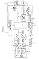
FIG. 2 is a block diagram illustrating configurations of a torque sensor and a controller according to an embodiment of the present invention; -
FIG. 3 is a flowchart illustrating an example of a signal switching procedure performed by a calculating unit of the torque sensor; -
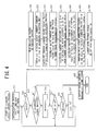
FIG. 4 is a flowchart illustrating an example of a steering assist control procedure performed by a micro control unit of a steering assist control device; -
FIG 5 is a block diagram illustrating configurations of a torque sensor and a controller according to a second embodiment of the present invention; -
FIG.. 6 is a flowchart illustrating an example of a signal switching procedure in the second embodiment; -
FIG. 7 is a flowchart illustrating an example of a steering assist control procedure in the second embodiment; -
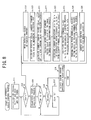
FIG. 8 is a flowchart illustrating an example of a steering assist control procedure in a third embodiment; -
FIG 9 is a flowchart illustrating a specific example of a diagnostic signal receiving process illustrated inFIG 8 ; -
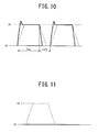
FIG. 10 is a waveform diagram illustrating a reception state of a diagnostic signal which is used to describe operations in the third embodiment; and -
FIG. 11 is a waveform diagram illustrating a reception state of a received signal during disconnection. - Hereinafter, embodiments of the present invention will be described with reference to the accompanying drawings.
-
FIG. 1 is a diagram illustrating an example of the whole configuration of an electric power steering apparatus according to a first embodiment. of the present invention. - In the electric power steering apparatus, a steering effort which is applied to a
steering wheel 1 by a driver is transmitted to asteering shaft 2 including aninput shaft 2a and anoutput shaft 2b One end of theinput shaft 2a of thesteering shaft 2 is linked to thesteering wheel 1 and the other end is linked to one end of theoutput shaft 2b via atorque sensor 3 as a detection unit of a physical quantity detecting device. - The steering effort transmitted to the
output shaft 2b is transmitted to alower shaft 5 via auniversal joint 4 and is then transmitted to apinion shaft 7 via auniversal joint 6.. The steering effort transmitted to thepinion shaft 7 is transmitted to tie rods 9 via a steering gear 8 to turn steered wheels not illustrated Here, the steering gear 8 employs a rack-and-pinion type including apinion 8a linked to the pinion shaft. 7 and arack 8b engaging with thepinion 8a, and converts a rotational motion transmitted to thepinion 8a into a linear motion by the use of therack 8b. - A
steering assist mechanism 10 that transmits a steering assist force to theoutput shaft 2b is linked to theoutput shaft 2b of thesteering shaft 2. Thesteering assist mechanism 10 includes adeceleration mechanism 11 linked to theoutput shaft 2b and anelectric motor 12 linked to thedeceleration mechanism 11 to generate the steering assist force to be applied to the steering apparatus. - The
torque sensor 3 is configured to detect the steering torque applied to thesteering wheel 1 and transmitted to theinput shaft 2a and includes, for example, asensor unit 3a of a pulse width modulation (PWM) output type. Thesensor unit 3a includes atorque sensor unit 3b, a calculatingunit 3c, asignal output unit 3d, and apower supply circuit 3e. - The
torque sensor unit 3b converts the steering torque into a torsion angle displacement of a torsion bar (not illustrated) interposed between theinput shaft 2a and theoutput shaft 2b, converts the torsion angle displacement, for example, into a current variation, and outputs the current variation. For example, as disclosed inJP 2006-267045 A torque sensor unit 3b includes plural elongated protrusions that are formed on the outer circumferential surface of any one of theinput shaft 2a and theoutput shaft 2b so as to extend in an extension direction, a cylindrical member that is fixed to the other of theinput shaft 2a and theoutput shaft 2b so as to face the elongated protrusions and that has a rectangular window in the circumferential direction, at least two detection coils of which impedance varies in the opposite directions depending on a torque generated in a rotating shaft fixed to the outer circumference of the cylindrical member, a bridge circuit having resistors individually connected in series to the two detection coils so as to detect impedance variations of the detection coils, and an AC signal source that supplies an AC signal to the bridge circuit The torque sensor unit amplifies a voltage across the detection coils of the bridge circuit, A/D converts the amplified voltage, and outputs the converted voltage as a digital voltage signal - The calculating
unit 3c receives the digital voltage signal outputted from thetorque sensor unit 3b, performs a predetermined torque computing process on the basis of the received digital voltage signal to calculate a torque detection value, and generates a pulse-width modulated (PWM) signal St as a torque detection signal with a pulse width of a duty ratio in a predetermined effective range (for example, 5% to 95%) depending on the calculated torque detection value. - The calculating
unit 3c generates a diagnostic signal Sd instead of the pulse-width modulated signal as the torque detection signal for a predetermined period of time after a supply of a power supply voltage from apower supply circuit 3e is started. The diagnostic signal Sd is set to have a duty ratio of 1% to 4% or a duty ratio of 96% to 99% which is out of the effective range of the pulse-width modulated signal as the torque detection signal, and is distinguishable from the pulse-width modulated signal St as the torque detection signal. - The calculating
unit 3c includes a signal switching unit 3ca that switches between the pulse-width modulated signal St and the diagnostic signal Sd. The signal switching unit 3ca selects the diagnostic signal Sd for a predetermined period of time after the supply of the power supply voltage from thepower supply circuit 3e is started, and selects the pulse-width modulated signal St after the predetermined period of time elapses. - The calculating
unit 3c performs a signal switching process illustrated inFIG. 3 when the supply of power is started. In the signal switching process, first, as the initialization process of step S1, a diagnostic period flag F1 is set to "1", the diagnostic period flag F1 indicating that a predetermined diagnostic period after the time of power-up does not elapse, and a variable N for counting the diagnostic period is cleared to "0". - Subsequently, it is determined in step S2 whether or not the diagnostic period flag F1 is set to "1". When it is determined that the diagnostic period flag F1 is set to "1", the diagnostic signal generated as a pulse-width modulated (PWM) signal which is set to have any of a duty ratio of 1% to 4% and a duty ratio of 96% to 99% which are out of the effective range of the above-mentioned pulse-width modulated (PWM) signal is outputted to the
signal output unit 3d in step S3 and then the process goes to step S4. - In step S4, the variable N for counting the diagnostic period increases by "1" and it is determined in step S5 whether or not the variable N reaches a predetermined number Ns. When it is determined that "N<Ns", the process returns to step S2. When it is determined that "N≥Ns", the diagnostic period flag F1 is reset to "0" in step S6 and then the process returns to step S2.
- On the other hand, when it is determined in step S2 that the diagnostic period flag F1 is "0", the digital voltage signal outputted from the
torque sensor unit 3b is read in step S7 and then the process goes to step S8 - In step S8, a torque detection value calculating process is performed. In the torque detection value calculating process, a torque detection value is calculated by calculating difference signals of the read digital voltage signals, full-wave rectifying and averaging the difference signals, and adjusting a neutral voltage thereof.
- Subsequently, in step S9, a duty ratio is calculated, for example, by referring to a duty ratio calculation map on the basis of the calculated torque detection value, the pulse-width modulated signal St with the calculated duty ratio is outputted to the
signal output unit 3d, and then the process returns to step S2. - The signal switching process illustrated in
FIG. 3 corresponds to the signal switching unit 3ca. - The
signal output unit 3d outputs the pulse-width modulated signal outputted from the calculatingunit 3c as the torque detection signal to the output terminal tso via anoise filter 3f. - The
power supply circuit 3e converts a power supply voltage, which is supplied from the steering assistcontrol device 20 as the control unit to be described later via anoise filter 3g, into a voltage used in the calculatingunit 3c and thesignal output unit 3d and outputs the converted voltage to the calculatingunit 3c and thesignal output unit 3d. - The torque detection signal T outputted from the
torque sensor 3 is inputted to the steering assistcontrol device 20. - The steering
assist control device 20 operates with a supply of power from an in-vehicle battery 21 and controls driving of anelectric motor 12 including, for example, a three-phase brushless motor applying a steering effort to the steering apparatus. The negative electrode of thebattery 21 is grounded, and the positive electrode thereof is linked to the steering assistcontrol device 20 via anignition switch 22 for starting an engine and is also connected directly to the steering assistcontrol device 20 without interposing theignition switch 22 - As illustrated in
FIG. 2 , the steering assistcontrol device 20 receives the torque detection signal T detected by thetorque sensor 3 via anoise filter 23 and receives a vehicle velocity detection value Vs detected by thevehicle velocity sensor 24 via a vehicle controller area network (CAN) 25 which is a network connecting controllers in a vehicle. - The steering
assist control device 20 includes a micro control unit (MCU) 31 as a control unit constituted of, for example, a microcomputer. The steeringassist control device 20 includes amotor drive circuit 32, an FETgate drive circuit 33, and a motor current detectingcircuit 34. - The
micro control unit 31 calculates phase voltage command values for causing theelectric motor 12 to generate the steering assist force on the basis of the detection signals of various sensors and generates a pulse-width modulated (PWM) control signal on the basis of the calculated phase voltage command values. - The
motor drive circuit 32 includes field effect transistors (FET) that drive theelectric motor 12. - The FET
gate drive circuit 33 controls gate voltages of the field effect transistors of themotor drive circuit 32 on the basis of the PWM control signal outputted from themicro control unit 31. - The motor current detecting
circuit 34 detects phase currents supplied for phases of theelectric motor 12. - The motor current detecting
circuit 34 detects motor currents of a U phase, a V phase, and a W phase from the voltages across motor current detection resistors inserted into the negative electrodes of a U-phase arm, a V-phase arm, and a W-phase arm of an inverter circuit constituting themotor drive circuit 32 - The steering
assist control device 20 includes apower supply relay 35 that supplies power from thebattery 21 to themotor drive circuit 32. The ON/OFF state of thepower supply relay 35 is controlled by themicro control unit 31. The steeringassist control device 20 includes aCAN interface circuit 36 that receives the vehicle velocity detection value Vs by performing an interface process with thevehicle CAN 25. - Furthermore, the steering assist
control device 20 includes thepower supply circuit 37 that is linked to thebattery 21 via theignition switch 22 and that is linked to the battery via thepower supply relay 35. Thepower supply circuit 37 includes a regulator that lowers a battery voltage (for example, 12 V) to an internal voltage (for example, 5 V) necessary for themicro control unit 31 or the FETgate drive circuit 33. - The internal voltage outputted from the
power supply circuit 37 is supplied as an internal power to themicro control unit 31, the FETgate drive circuit 33, the motor current detectingcircuit 34, theCAN interface circuit 36, and the like, and is supplied to thetorque sensor 3 via a power supply output terminal tpo. - Additionally, as illustrated in
FIG. 2 , themicro control unit 31 includes anabnormality determining unit 31a that determines abnormality of a signal transmission line to thetorque sensor 3. Themicro control unit 31 performs a steering assist control process illustrated inFIG. 4 . - The steering assist control process is started when the
ignition switch 22 is turned on and power is supplied to themicro control unit 31 from the power supply circuit 27. - That is, first, in step S11, an initialization process is performed to set the diagnostic state flag F2 to "1", to clear the variable N2 for counting the diagnostic signal reception number to "0", to set a timer to start counting of the diagnostic period, and to control the
power supply relay 25 so as to be turned on. - Subsequently, in step S12, it is determined whether or not the diagnostic state flag F2 is set to "1". When it is determined that the diagnostic state flag F2 is set to "1", the process goes to step S13.
- In step S13, it is determined whether or not the diagnostic signal with a predetermined duty ratio outputted from the calculating
unit 3c of the above-mentionedtorque sensor 3 is received. When it is determined that the diagnostic signal is received, the variable N2 indicating the diagnostic signal reception number increases by "1" in step S14 and then the process goes to step S15. When it is determined that the diagnostic signal is not received, the process immediately goes to step S15. - In step S15, it is determined whether or not the diagnostic period counted by the timer is up. When it is determined that the diagnostic period is not up, the process returns to step S12. When it is determined that the diagnostic period is up, it is determined in step S16 whether or not the variable N2 reaches a predetermined value N2s.
- When it is determined in step S16 that "N2≥N2s", it is determined that the signal transmission line between the
torque sensor 3 and themicro control unit 31 is normal, the diagnostic state flag F2 is reset to "0", and the process returns to step S12. - When it is determined that "N2<N2s", it is determined that the signal transmission line between the
torque sensor 3 and themicro control unit 31 is abnormal and the process goes to step S18 - In step S18, a torque sensor abnormality alarm signal is outputted to an
alarm circuit 40, a torque sensor abnormality alarm including sound, light, image information, or the like is issued from thealarm circuit 40, and then the steering assist control process is terminated. Here, when it is determined that the torque sensor is abnormal, a controlling value may be switched to a known alternative torque value and then the assist operation may be continued. - On the other hand, when it is determined in step S12 that the diagnostic state flag F2 is reset to "0", detection values of various sensors such as the
torque sensor 3, thevehicle velocity sensor 24, and the motor current detecting circuit. 34 are read in step S19. Then, in step S20, a steering assist current command value Iref is calculated by referring to a steering assist current command value calculation map indicating the relationship between the steering torque and the steering assist current command value using the vehicle velocity as a parameter on the basis of the steering torque T and the vehicle velocity detection value Vs and the process goes to step S21. - In step S21, a d-q axis current command value computing process is performed on the basis of the calculated steering assist current command value Iref to calculate a d-axis current command value Idref and a q-axis current command value Iqref. Then, in step S22, a two-phase to three-phase transformation process is performed to calculate three-phase motor current command values Iuref to Iwref.
- Subsequently, current deviations ΔIu to ΔIw are calculated by subtracting the motor currents Iu to Iw from the motor current command values Iuref to Iwref in step S23, voltage command values Vuref to Vwref are calculated by performing a PI control process on the current deviations ΔIu to ΔIw in step S24, and then the process goes to step S25.
- In step S25, the duty ratio is calculated on the basis of the calculated voltage command values Vuref to Vwref and a pulse width modulating process is performed to generate a gate control signal. Then, in step S26, the generated gate control signal is outputted to the FET
gate drive circuit 33 and then the process returns to step S19. - In the procedure illustrated in
FIG. 4 , the processes of steps S11 to S18 correspond to theabnormality determining unit 31a. - The
power supply relay 35 is returned to the OFF state after various control processes of themicro control unit 31 are terminated - When it is assumed that a vehicle stops, the
ignition switch 22 is turned off, and thepower supply relay 35 is in the OFF state, power from thebattery 21 is not supplied to thepower supply circuit 37 of the steering assistcontrol device 20 in this state and thus the internal voltage is not outputted from thepower supply circuit 37.. Accordingly, themicro control unit 31, themotor drive circuit 32, the FETgate drive circuit 33, the motor current detectingcircuit 34, and thealarm circuit 40 are in a deactivated state and theelectric motor 12 is also in a non-rotating state. - Similarly, in the
torque sensor 3, since the internal power is not supplied to thepower supply circuit 3e from thepower supply circuit 37 of the steering assistcontrol device 20, thetorque sensor unit 3b, the calculatingunit 3c, and the signal output unit. 3d are in a deactivated state. - When a driver starts an engine by turning on the
ignition switch 22 in this state, power from thebattery 21 is supplied to thepower supply circuit 37 via theignition switch 22. Accordingly, for example, the internal voltage of 5 V is supplied to themicro control unit 31, the FETgate drive circuit 33, the motor current detectingcircuit 34, and thealarm circuit 40 from thepower supply circuit 37 and these units are switched to an activated state. - At the same time, the internal voltage outputted from the
power supply circuit 37 is supplied to thepower supply circuit 3e of thetorque sensor 3 via the power supply output terminal tpo, the power supply input terminal tpi, and thenoise filter 3g. Accordingly, the internal voltage is outputted from thepower supply circuit 3e to thetorque sensor unit 3b, the calculatingunit 3c, and thesignal output unit 3d and these units are switched to an activated state. - At this time, the signal switching procedure described with reference to
FIG. 3 is started by the calculatingunit 3c of thetorque sensor 3. First, the initialization process is performed to set the diagnostic period flag F1 to "1" and to clear the variable N for counting the diagnostic period to "0" (step S1). - Subsequently, since the diagnostic period flag F1 is set to "1", the process goes from step S2 to step S3 and the diagnostic signal with a predetermined duty ratio which is out of the effective range of the pulse-width modulated (PWM) signal indicating a normal steering torque detection value is outputted to the
signal output unit 3d. - Thereafter, the variable N for counting the diagnostic period increases by "1" (step S4), it is then determined whether or not the diagnostic period variable N reaches a predetermined number Ns (step S5), and the output of the diagnostic signal is repeated until the diagnostic period variable N reaches the predetermined number.
- On the other hand, in the steering assist
control device 20, the steering assist control procedure illustrated inFIG.. 4 is similarly started by themicro control unit 31. In the initialization process, the diagnostic state flag F2 is set to "1", the variable N2 indicating the diagnostic signal reception number is cleared to "0", and furthermore, the timer for setting the diagnostic period is set (step S11). - Subsequently, since the diagnostic state flag F2 is set to "1", the process goes from step S12 to step S13 and it is determined whether or not the diagnostic signal with a predetermined duty ratio is received from the
torque sensor 3. At this time, when it is determined that the diagnostic signal is received, the variable N2 indicating the diagnostic signal reception number increases by "1" and then it is determined whether or not the diagnostic period counted by the timer is up. Since the timer is set just before, the process returns to step S12. - The process of counting the diagnostic signal reception number from steps S12 to S15 are repeatedly performed until the diagnostic period counted by the timer is up, that is, until the diagnostic period set by the calculating
unit 3c of thetorque sensor 3 elapses. - When the diagnostic period elapses, the diagnostic period flag F1 is reset to "0" in the torque computing process performed by the calculating
unit 3c of the torque sensor 3 (step S6), the process goes from step S2 to step S7, and the torque detection value computing process is performed. In the torque detection value computing process, the torque detection value is calculated by reading the output voltages of the bridge circuit from the normaltorque sensor unit 3b, full-wave rectifying and averaging the difference voltages of the output voltages, and adjusting the neutral voltage (step S8). - The duty ratio depending on the torque detection value is calculated by referring to the duty ratio calculation map on the basis of the calculated torque detection value, the pulse-width modulated (PWM) signal with the calculated duty ratio is outputted to the
signal output unit 3d, and the pulse-width modulated (PWM) signal is outputted as the torque detection signal from thesignal output unit 3d to the output terminal tso. - Similarly, the
micro control unit 31 of the steering assistcontrol device 20 repeatedly performs a diagnostic signal receiving process for the diagnostic period from the time of power-up and increases the variable N2 indicating the diagnostic signal reception number every time the diagnostic signal is received.. Accordingly, when the signal transmission system between thesensor unit 3a of thetorque sensor 3 and themicro control unit 31 of the steering assistcontrol device 20 is not abnormal, the variable N2 indicating the diagnostic signal reception number becomes equal to or greater than a predetermined value N2s. Accordingly, when the diagnostic period counted by the timeris up, the process goes from step S15 to step S17 via step S16 and the diagnostic state flag F2 is reset to "0". - Therefore, when the process returns to step S12, the process goes from step S12 to step S19, the torque detection signal T, the vehicle velocity detection value Vs, the motor current detection value, and the like are read, and the steering assist current command value Iref is calculated by referring to the steering assist current command value calculation map on the basis of the read torque detection signal T and the read vehicle velocity detection value Vs (step S20).
- The d-qaxis command value computing process is performed on the basis of the calculated steering assist current command value Iref to calculate the d-axis current command value Idref and the q-axis current command value Iqref (step S22), and the calculated d-axis current command value Idref and the calculated q-axis current command value Iqref are processed by using a two-phase to three-phase transformation to calculate the three-phase motor current command values Iuref to Iwref (step S23).
- Subsequently, the motor current detection values Iu to Iw are subtracted from the calculated motor current command values Iuref to Iwref, respectively, to calculate the current deviations ΔIu to ΔIw (step S23), the PI control process is performed on the calculated current deviations ΔIu to ΔIw to calculate the voltage command values Vuref to Vwref (step S24), the pulse width modulating process is performed on the basis of the calculated voltage command values Vuref to Vwref to generate the gate control signal (step S25), and the generated gate control signal is outputted to the FET gate drive circuit 33 (step S26).
- Accordingly, the gate control signal is outputted from the FET
gate drive circuit 33 to themotor drive circuit 32 and the three-phase motor currents Iu to Iw are outputted from themotor drive circuit 32 to theelectric motor 12 Therefore, theelectric motor 12 is driven to rotate so as to generate a steering assist torque depending on the steering torque detection value, and the generated steering assist torque is transmitted to theoutput shaft 2b of thesteering shaft 2 via thedeceleration mechanism 11. As a result, it is possible to steer thesteering wheel 1 with a small steering effort. - On the other hand, when the variable N2 indicating the diagnostic signal reception number is less than a predetermined value N2s in the diagnosis process at the time of power-up, it is determined that abnormality occurs in the signal transmission system between the calculating
unit 3c of thetorque sensor 3 and themicro control unit 31 of the steering assistcontrol device 20. - Accordingly, when the diagnostic period counted by the timer is up and the diagnostic period elapses, the process goes from step S16 to step S18, the torque sensor abnormality alarm signal is outputted to the
alarm circuit 40, and then the steering assist control process is terminated.. Thealarm circuit 40 issues an alarm using sound, light, image information, or the like to notify a driver of the abnormality of the torque detection value transmission system. When it is determined that the torque sensor is abnormal, the controlling value may be switched to the known alternative torque value and then the assist operation may be continued. - As a result, it is possible to surely prevent the steering assist control process from being performed in a state where the steering torque detection signal read by the
micro control unit 31 is abnormal. - In this way, according to the first embodiment, the calculating
unit 3c of thetorque sensor 3 generates and outputs the diagnostic signal to themicro control unit 31 as a control unit of the steering assistcontrol device 20 at least at the time of starting the supply of power, and it is determined whether or not themicro control unit 31 normally receives the diagnostic signal. Accordingly, it is possible to accurately detect the abnormality of the signal transmission system including the noise filters 3f and 14 between the calculatingunit 3c of thetorque sensor 3 and themicro control unit 31, thereby improving reliability of the electric power steering apparatus. - In addition, since the diagnostic signal used to detect abnormality uses a duty ratio of 1% to 4% or a duty ratio of 96% to 99% out of the effective range (duty ratio of 5% to 95%) of the pulse-width modulated (PWM) signal in which a normal torque detection signal is outputted, it is possible to accurately determine whether or not the diagnostic signal is received at the time of the diagnostic process of the
micro control unit 31. - Furthermore, even when the diagnostic signal is erroneously outputted from the calculating
unit 3c of thetorque sensor 3 in the normal operation, the micro control unit. 31 does not recognize the erroneous diagnostic signal as the torque detection signal and it is thus possible to avoid the possibility of occurrence of an erroneous operation. - Additionally, since the output computing process of a diagnostic signal and the reception computing process of a diagnostic signal are performed as the respective software processes, the present invention can be easily applied to an existing electric power steering apparatus not having a signal transmission system diagnosing function by only changing programs of the calculating
unit 3c of thetorque sensor 3 and themicro control unit 31 of the steering assistcontrol device 20. - In the first embodiment, the descriptions are given for a case where the diagnostic signal is outputted from the calculating
unit 3c of thetorque sensor 3 at the time of power-up and the diagnostic signal is received by themicro control unit 31 of the steering assistcontrol device 20, but the present invention is not limited to this case - That is, the calculating
unit 3c of thetorque sensor 3 may set the diagnostic period flag F1 to "1", perform the diagnostic signal output process (steps S2 to S6), and output the diagnostic signal for a predetermined period of time, at a fixed period of time T1 after the time of power-up. - Then, the
micro control unit 31 of the steering assistcontrol device 20 performs the diagnostic signal determining process (steps S12 to S18) for a predetermined period of time by setting the diagnostic state flag F2 to "1" and setting the timer, at a fixed period of time T1 equal to that in the calculatingunit 3c after the time of power-up. - In the diagnostic signal determining process, it may be determined whether or not abnormality occurs in the signal transmission system between the calculating
unit 3c of thetorque sensor 3 and themicro control unit 31 of the steering assistcontrol device 20 on the basis of the reception state of the diagnostic signal. In this case, the output period of the diagnostic signal is preferably set to a short period so as to reduce an influence on the steering assist control by the continuously-out.put torque detection signals. - A second embodiment of the present invention will be described below with reference to
FIG. 5 . - In the second embodiment, the steering assist
control device 20 can request thetorque sensor 3 to transmit a diagnostic signal. - That is, in the second embodiment, a
signal transmission line 41 for transmitting a diagnostic signal transmission request signal is provided between themicro control unit 31 of the steering assistcontrol device 20 and the calculatingunit 3c of thetorque sensor 3 as illustrated inFIG. 5 . - In the signal switching process which is performed by the calculating
unit 3c of thetorque sensor 3, step S31 is performed after step S9 as illustrated inFIG. 6 . In step S31, it is determined whether or not the diagnostic signal transmission request signal is received from themicro control unit 31 of the steering assistcontrol device 20 is performed. - When it is determined in step S31 that the diagnostic signal transmission request signal is not received, the process returns to step S2. When it is determined that the diagnostic signal transmission request signal is received, the diagnostic period flag F1 is set to "1" in step S32 and then the process returns to step S2.
- Furthermore, in the steering assist control process which is performed by the
micro control unit 31 of the steering assistcontrol device 20, step S41 is add after step S26 as illustrated inFIG. 7 . In step S41, it is determined whether or not the steering torque detection value is "0" or a value within a dead zone in the vicinity of "0". - When it is determined in step S41 that the steering torque detection value is not "0" nor a value within a dead zone in the vicinity of "0", a variable N3 to be described later is cleared to "0" in step S42 and then the process returns to step S19. On the other hand, when it is determined that the steering torque detection value is "0" or a value within a dead zone in the vicinity of "0", it is determined that the steering is held at a neutral position, the variable N3 for counting the duration of the steering-held state increases by "1" in step S43, and then the process goes to step S44.
- In step S44, it is determined whether or not the variable N3 reaches a predetermined value N3s. When it is determined that "N3<N3s", the process returns to step S19. When it is determined that "N3≥N3s", the diagnostic signal transmission request signal is transmitted to the
signal transmission line 41 in step S45 Subsequently, in step S46, the diagnostic state flag F2 is set to "1", the timer is set, and then the process returns to step S12. - According to the second embodiment, similarly to the first embodiment, initial abnormality diagnostic process is performed at the time of power-up. In the abnormality diagnostic process, the abnormality of the signal transmission line between the calculating
unit 3c of thetorque sensor 3 and themicro control unit 31 of the steering assistcontrol device 20 is diagnosed. Furthermore, in the steering assist control process of themicro control unit 31 of the steering assistcontrol device 20, when the state where the steering torque detection value is "0" or a value within a dead zone in the vicinity of "0" is maintained for a predetermined period of time, themicro control unit 31 transmits the diagnostic signal transmission request signal to the calculatingunit 3c of thetorque sensor 3 so as to cause the calculatingunit 3c to transmit the diagnostic signal. - Accordingly, it is possible to diagnose the abnormality of the signal transmission system between the calculating
unit 3c of thetorque sensor 3 and themicro control unit 31 of the steering assistcontrol device 20 during operation of the steering assistcontrol device 20 and also to diagnose the abnormality even after the time of power-up, thereby further improving reliability.. - In the second embodiment, the descriptions are given for a case where the diagnostic signal transmission request signal is transmitted to the calculating
unit 3c of thetorque sensor 3 via thesignal transmission line 41 when the torque detection signal is "0" or a value within a dead zone in the vicinity of "0", but the present invention is not limited to this case. - That is, in the present invention, a steering angle sensor that detects a steering angle of the
steering wheel 1 may be provided, and the diagnostic signal transmission request signal may be transmitted when a state where the steering angle is located at the neutral position (="0") indicating straight traveling is maintained for a predetermined period of time. In brief, the diagnostic signal transmission request signal may be transmitted during the period in which the transmitting does not affect on the steering assist control process. The diagnostic signal transmission request signal may be transmitted at a fixed period of time. - A third embodiment of the present invention will be described below with reference to
FIGS. 8 and9 . - In the third embodiment, the abnormality of the noise filters 3f and 23 interposed between the
torque sensor unit 3a of thetorque sensor 3 and the micro control unit. 31 of the steering assistcontrol device 20 is detected. - That is, in the third embodiment, the
abnormality determining unit 31a of themicro control unit 31 illustrated inFIG. 2 in the first embodiment is used to detect the abnormality of the noise filters 3f and 23. - That is, the
micro control unit 31 performs a steering assist control process illustrated inFIG. 8 . - The steering assist control process includes step S50. In step S50, a diagnostic signal receiving process is performed instead of the processes of steps S13 and S14 in the steering assist control process illustrated in
FIG. 4 . - In the diagnostic signal receiving process of step S50, as illustrated in
FIG. 9 , it is first determined in step S51 whether or not the received signal rises from 0 V. When it is determined that the received signal does not rise, the diagnostic signal receiving process is terminated without performing any process and then the process goes to step S15 illustrated inFIG. 8 . - When it is determined in step S51 that the received signal rises, a rise counter including a software counter is activated to start a counting in step S52, so as to count at a constant a cycle shorter than the rise time of the received signal.
- Subsequently, in step S53, it is determined whether or not the received signal level reaches a set level of, for example, 5 V which is the power supply voltage. When it is determined in step S53 that the received level does not reach the set level, the process waits until the received level reaches the set level. When it is determined that the received level reaches the set level, the process goes to step S54.
- The count value Tn1 of the rise counter is read in step S54, and it is determined in step S55 whether or not the read count value Tn1 is smaller than a set count value Tns previously set to a value smaller than the count value in a state where both of the noise filters 3f and 23 are normal.
- The determination of step S55 is to determine whether or not the rising of the received signal is rapid. That is, since the noise filters 3f and 23 are generally constituted of a low-pass filter and serve as an integration element, the received signal rises at a relatively slow change rate as indicated by a dotted line in
FIG. 10 when the noise filters 3f and 23 are normal. However, when the noise filters 3f and 23 are abnormal and cannot serve as a filter, the integration elements do not operate and thus the received signal rides rapidly as indicated by a solid line inFIG. 10 . - Therefore, by causing the rise counter to count the period of time in which the received signal rides from 0 V to the set level of 5 V, it is possible to determine whether or not the noise filters 3f and 23 are normal on the basis of the count value.
- When it is determined that "Tn1<Tns", it is determined that abnormality occurs in any one of the noise filters 3f and 23, a filter abnormality flag FNA1 indicating that the noise filters 3f and 23 are abnormal is set to "1" in step S56, and then the process goes to step S58 When it is determined that "Tn1>Tns", it is determined that the noise filters 3f and 23 are normal, the filter abnormality flag FNA1 is reset to "0" in step S57, and then the process goes to step S58.
- In step S58, it is determined whether or not the received signal falls. When it is determined that the received signal does not fall, the process waits until the received signal falls. When it is determined that the received signal falls, the process goes to step S59.
- A fall counter including a software counter is activated to start a counting in step S59 so as to count at a constant cycle shorter than the rise time of the received signal, the counting of the rise counter is stopped in step S60, and then the process goes to step S61. By stopping the counting of the rise counter at the time of falling of the received signal, the count value of the rise counter indicates the duration Ton of the ON section of the received signal.
- In step S61, it is determined whether or not the received signal level reaches 0 V. When it is determined that the received signal level does not reach 0 V, the process waits until the received signal level reaches 0 V. When it is determined that the received signal level reaches 0 V, the process goes to step S62.
- The count value Tn2 of the fall counter is read in step S62, and it is determined in step S63 whether or not the read count value Tn2 is smaller than a set count value Tns previously set to a value smaller than the count value in a state where both of the noise filters 3f and 23 are normal.
- The determination of step S63 is to determine whether or not the fall of the received signal is rapid. That is, when the noise filters 3f and 23 are normal, the received signal falls at a relatively slow change rate as indicated by a dotted line in
FIG. 10 . However, when the noise filters 3f and 23 are abnormal and cannot serve as a filter, the integration elements do not operate and thus the received signal falls rapidly as indicated by a solid line inFIG 10 . - Therefore, by causing the fall counter to count the period of time in which the received signal falls from 5 V as the power supply voltage to 0 V, it is possible to determine whether or not the noise filters 3f and 23 are normal on the basis of the count value.
- When it is determined that "Tn2<Tns", it is determined that abnormality occurs in any one of the noise filters 3f and 23, a filter abnormality flag FNA2 indicating that the noise filters 3f and 23 are abnormal is set to "1" in step S64, and then the process goes to step S66. When it is determined that "Tn2≥Tns", it is determined that the noise filters 3f and 23 are normal, the filter abnormality flag FNA2 is reset to "0" in step S65, and then the process goes to step S66.
- In step S66, it is determined whether or not the received signal rises again. When it is determined that the received signal does not rise, the process waits until the received signal rises. When it is determined that the received signal rises, the process goes to step S67.
- The counting of the fall counter is stopped in step S67 and then the process goes to step S68. The count value Tn2 of the fall counter indicates the duration Toff of the OFF section of the received signal..
- In step S68, the duty ratio D of the received signal is calculated according to Expression (1) on the basis of the duration Ton of the ON section of the received signal indicated by the count value Tn1 of the stopped rise counter and the duration Toff of the OFF section of the received signal indicated by the count value Tn2 of the stopped fall counter, and then the process goes to step S69.

- In step S69, it is determined whether or not the received signal is a diagnostic signal by determining whether or not the calculated duty ratio D corresponds to the set duty ratio of the diagnostic signal Sd. When it is determined that the received signal is not a diagnostic signal, the diagnostic signal receiving process is terminated and the process goes to step S15 of
FIG. 8 . - On the other hand, when it is determined in step S69 that the received signal is a diagnostic signal, it is determined in step S70 whether or not any one of the filter abnormality flags FNA1 and FNA2 is set to "1". When it is determined that any one of the filters abnormality flags FNA1 and FNA2 is set to "1", an alarm signal indicating abnormality of the noise filter is outputted to the
alarm circuit 40 in step S71 and then the process goes to step S72. When it is determined that both of the filter abnormality flags FNA1 and FNA2 are reset to "0", the process immediately goes to step S72. - The variable N2 indicating the diagnostic signal reception number increases by "1" in step S72, the diagnostic signal receiving process is terminated, and then the process goes to step S15 of
FIG. 8 . - According to the third embodiment, in the diagnostic signal receiving process illustrated in
FIG 9 at the time of power-up, the rise time Tn1 of the received signal is measured in steps S51 to S54, and the fall time Tn2 of the received signal is measured in steps S58 to S62. - The rise time Tn1 and the fall time Tn2 indicate the change rates, that is, slopes, of the rise and the fall of the received signal. Therefore, when the noise filters 3f and 23 are normal and the received signal is received, as indicated by the dotted line in
FIG. 10 , the rise and the fall of the received signal are slow, the change rates thereof are small, the rise time Tn1 and the fall time Tn2 are longer than the set time Tns, and thus it can be determined that the noise filters 3f and 23 are normal.. - However, for example, when both of the noise filters 3f and 23 are abnormal, the rise and the fall of the received diagnostic signal become rapider as indicated by the solid line in
FIG. 10 , the count value Tn1 of the rise counter read in step S54 is smaller than the set count value Tns, and the count value Tn2 of the fall counter read in step S62 is smaller than the set count value Tns. - Accordingly, the filter abnormality flag FNA1 is set to "1" in step S56, and the filter abnormality flag FNA2 is set to "1" in step S64.
- Thereafter, when the received signal rises again, the process goes from step S66 to step S67, the rise counter is stopped, the duty ratio D is calculated according to Expression (1) on the basis of the count value Tn1, that is, the ON time Ton, of the stopped rise counter and the count value Tn2, that is, the OFF time Toff, of the stopped rise counter in step S68.
- When the calculated duty ratio D is out of the effective range of the duty ratio of the pulse-width modulated signal St in which the torque detection signal is outputted, it can be determined that the received signal is the diagnostic signal When it is determined that the received signal is the diagnostic signal, it is determined in step S70 whether or not the filter abnormality flag FNA1 or FNA2 is set to "1". When it is determined that any one of the filter abnormality flags FNA1 and FNA2 is set to "1", the alarm signal indicating the abnormality of the noise filter is outputted to the
alarm circuit 40 to issue an alarm in step S71. - When both of the filter abnormality flags FNA1 and FNA2 are reset to "0", it is determined that the noise filters 3f and 23 are normal.
- On the other hand, when the received signal does not rise from 0 V as indicated by a solid line in
FIG. 11 , the diagnostic signal receiving process is terminated without performing any process after step S51. Accordingly, when the state where the received signal does not rise is maintained, the variable N2 indicating the diagnostic signal reception number is maintained in "0", and thus it can be determined that the transmission line between the torque sensor unit. 3a and themicro control unit 31 of the steering assistcontrol device 20 is in a disconnected state. - In the third embodiment, in order to determine whether or not the noise filters 3f and 23 are normal, the time until the received signal rises to the
set voltage 5 V from 0 V as the rising state of the received signal is measured, and the time until the received signal reaches 0 V from the setvoltage 5 V as the falling state of the received signal is measured. However, the present invention is not limited to the above-mentioned configuration A voltage after a predetermined time elapses from the time point at which the rise or fall is detected may be detected to determine the rising state and the falling state of the received signal, or the period of time in which the received signal rises to a predetermined voltage and the period of time in which the received signal falls to a predetermined voltage may be measured. In brief, values corresponding to the change rates of the rise and the fall of the received signal have only to be detected. The present invention is not limited to the case where both the rising state and the falling state of the received signal are measured, but any one thereof may be measured. - In the third embodiment, the descriptions are given for a case where the process of determining abnormality of the noise filters is applied to the first embodiment, but the process of determining abnormality of the noise filters may be applied to the second embodiment.
- In the first to third embodiments, the descriptions are given for a case where the torque detection value is outputted in the form of a pulse-width modulated (PWM) signal from the calculating
unit 3c of thetorque sensor 3, but the present invention is not limited to this case. - That is, the present invention may employ any signal transmitting method such as using an analog or digital voltage signal corresponding to the torque detection value or using a pulse signal with a pulse interval corresponding to the torque detection value.
- In the first to third embodiments, the descriptions are given for a case where the abnormality of the signal transmission system is detected by causing the calculating
unit 3c of thetorque sensor 3 and themicro control unit 31 of the steering assistcontrol device 20 to generate the diagnostic signal and to receives the generated diagnostic signal by a software process. - The present invention is not limited to the above-mentioned configuration, but the
torque sensor 3 may be provided with a test signal forming circuit that outputs a test signal and a signal switching circuit that switches between the diagnostic signal of the test signal forming circuit and the torque detection signal calculated by the calculatingunit 3c. Similarly, the calculatingunit 3c and themicro control unit 31 may be constructed by hardware. Similarly, the calculatingunit 3c and themicro control unit 31 may be constructed by hardware. - In the first to third embodiments, the descriptions are given for a case where only the steering torque is detected as the physical quantity, but the present invention is not limited to this case. When a steering angel sensor that detects a steering angle as the physical quantity is provided, the
sensor unit 3a may be applied to the steering angle sensor Alternatively, two or more types of physical quantities may be detected by physical quantity sensors and the detected physical quantities may be supplied to the steering assist control device in a time division manner. The physical quantities to be detected are not limited to the steering torque and the steering angle, but the present invention may be used to detect arbitrary physical quantities such as a current, a voltage, a pressure, and a liquid level. - In the above-mentioned embodiments, the descriptions are given for a case where the physical quantity detecting device according to the present invention is applied to the electric power steering apparatus, but the present invention is not limited to this case. The present invention may be applied to a physical quantity detecting device including a detection unit that detects a physical quantity and a control unit that performs a control operation on the basis of the physical quantity detected by the detection unit, or a control device that controls any control target using the physical quantity detecting device.
-
- 1:
- steering wheel
- 2:
- steering shaft
- 3:
- torque sensor
- 3a:
- sensor unit
- 3b:
- torque sensor unit.
- 3c:
- calculating unit
- 3d:
- signal output unit
- 3e:
- power supply circuit
- 3f, 3g:
- noise filter
- 10:
- steering assist mechanism
- 11:
- deceleration mechanism
- 12:
- electric motor
- 20:
- steering assist control device
- 21:
- battery
- 22:
- ignition switch
- 23:
- noise filter
- 24:
- vehicle velocity sensor
- 25:
- vehicle CAN
- 31:
- micro control unit (MCU)
- 31a:
- abnormality determining unit
- 32:
- motor drive circuit
- 33:
- FET gate drive circuit
- 34:
- motor current detecting circuit
- 35:
- power supply relay
- 36:
- CAN interface
- 37:
- power supply circuit
- 40:
- alarm circuit
- 41:
- signal transmission line
Claims (9)
- A physical quantity detecting device comprising:a physical quantity detector configured to detect a physical quantity and to output a physical quantity detection signal; anda controller configured to receive the physical quantity outputted from the physical quantity detector via a transmission line and to perform a control operation on the basis of the physical quantity,wherein the physical quantity detector outputs a diagnostic signal for detecting abnormality of a transmission system between the controller and the physical quantity detector and the controller includes an abnormality determining unit configured to determine the abnormality of the transmission system on the basis of the diagnostic signal when receiving the diagnostic signal.
- The physical quantity detecting device according to claim 1, wherein the physical quantity detector includes a signal switch configured to switch between the physical quantity detection signal and the diagnostic signal.
- The physical quantity detecting device according to claim 1 or 2, wherein the physical quantity detector outputs the diagnostic signal for a predetermined period of time at a time of power-up.
- The physical quantity detecting device according to claim 1 or 2, wherein the physical quantity detector outputs the diagnostic signal for a predetermined period of time at a fixed period of time.
- The physical quantity detecting device according to any one of claims 1 to 4, wherein the physical quantity detector outputs a signal distinguishable from the physical quantity detection signal as the diagnostic signal
- The physical quantity detecting device according to any one of claims 1 to 5, wherein the controller is configured to output a diagnostic signal output request to the physical quantity detector, and
wherein the physical quantity detector outputs the diagnostic signal to the transmission line when receiving the diagnostic signal output request. - The physical quantity detecting device according to any one of claims 1 to 6, wherein the physical quantity detector outputs a pulse-width modulated signal with a pulse width corresponding to the physical quantity as the physical quantity detection signal, and
wherein the diagnostic signal is set to have a duty ratio out of an effective range of the pulse-width modulated signal. - The physical quantity detecting device according to claim 7, wherein the physical quantity detector outputs the physical quantity detection signal to the controller via a noise filter, and
wherein the abnormality determining unit determines whether or not the noise filter is abnormal by detecting a change of at least one of a rise and a fall of the received diagnostic signal. - An electric power steering apparatus comprising the physical quantity detecting device according to any one of claims 1 to 8,
wherein the physical quantity detecting device detects at least one physical quantity necessary for calculating a steering torque command value and outputs the physical quantity detection signal and the diagnostic signal, and
wherein the controller calculates the steering torque command value on the basis of the physical quantity detection signal of the physical quantity detecting device, and control an electric motor generating a steering assist force on the basis of the calculated steering torque command value, and the abnormality determining unit determines whether or not the transmission system is abnormal when receiving the diagnostic signal.
Applications Claiming Priority (3)
| Application Number | Priority Date | Filing Date | Title |
|---|---|---|---|
| JP2012224815 | 2012-10-10 | ||
| JP2013204890 | 2013-09-30 | ||
| PCT/JP2013/006025 WO2014057671A1 (en) | 2012-10-10 | 2013-10-09 | Device for detecting physical quantities and electromotive power steering device using same |
Publications (3)
| Publication Number | Publication Date |
|---|---|
| EP2907727A1 true EP2907727A1 (en) | 2015-08-19 |
| EP2907727A4 EP2907727A4 (en) | 2016-06-15 |
| EP2907727B1 EP2907727B1 (en) | 2017-05-31 |
Family
ID=50477153
Family Applications (1)
| Application Number | Title | Priority Date | Filing Date |
|---|---|---|---|
| EP13846141.3A Not-in-force EP2907727B1 (en) | 2012-10-10 | 2013-10-09 | Device for detecting physical quantities and electromotive power steering device using same |
Country Status (5)
| Country | Link |
|---|---|
| US (1) | US9573619B2 (en) |
| EP (1) | EP2907727B1 (en) |
| JP (1) | JP5858169B2 (en) |
| CN (1) | CN104271430B (en) |
| WO (1) | WO2014057671A1 (en) |
Cited By (1)
| Publication number | Priority date | Publication date | Assignee | Title |
|---|---|---|---|---|
| WO2015185417A1 (en) * | 2014-06-04 | 2015-12-10 | Conti Temic Microelectronic Gmbh | Device for actuating and/or monitoring a brushless direct current motor |
Families Citing this family (13)
| Publication number | Priority date | Publication date | Assignee | Title |
|---|---|---|---|---|
| JP6151849B2 (en) * | 2014-03-19 | 2017-06-21 | 日立オートモティブシステムズ株式会社 | Electric power steering device and control device for electric power steering device |
| CN107074273B (en) * | 2014-09-24 | 2020-07-31 | 日立汽车系统株式会社 | Control device and power steering device for vehicle-mounted equipment |
| CN106794809B (en) * | 2014-09-25 | 2018-02-13 | 日本精工株式会社 | The control device and control method of vehicle-mounted electronic device |
| JP6418063B2 (en) * | 2015-05-20 | 2018-11-07 | 株式会社デンソー | Sensor device, electric power steering device using the same, and control device |
| JP6390532B2 (en) * | 2015-06-12 | 2018-09-19 | 株式会社デンソー | Communications system |
| JP6679861B2 (en) * | 2015-09-15 | 2020-04-15 | 株式会社デンソー | Sensor device and electric power steering device using the same |
| US10343713B2 (en) * | 2016-01-14 | 2019-07-09 | Mitsubishi Electric Corporation | Electric power steering apparatus |
| CN106681139B (en) * | 2016-12-19 | 2020-01-14 | 重庆承亿机电设备有限公司 | Frequency converter frequency analog given automatic control method |
| JP6722355B2 (en) * | 2017-03-07 | 2020-07-15 | コンチネンタル オートモーティヴ ゲゼルシャフト ミット ベシュレンクテル ハフツングContinental Automotive GmbH | Apparatus and method for detecting manual steering wheel operation |
| JP6475791B2 (en) * | 2017-07-24 | 2019-02-27 | 本田技研工業株式会社 | Steering wheel unit |
| JP6514295B2 (en) * | 2017-10-02 | 2019-05-15 | 株式会社ショーワ | Failure detection device, electric power steering device |
| CN108556907A (en) * | 2018-04-10 | 2018-09-21 | 深圳市云图电装系统有限公司 | The control method of power steering, apparatus and system |
| JP7141893B2 (en) * | 2018-09-04 | 2022-09-26 | 日立Astemo株式会社 | steering device |
Family Cites Families (14)
| Publication number | Priority date | Publication date | Assignee | Title |
|---|---|---|---|---|
| ZA796811B (en) * | 1978-12-22 | 1980-11-26 | Lucas Industries Ltd | Motor vehicle electrical system |
| JPS58134394A (en) * | 1982-02-04 | 1983-08-10 | 株式会社共和電業 | Physical quality measuring apparatus with function of measuring temperature |
| JPS62180500A (en) * | 1986-02-04 | 1987-08-07 | 日産自動車株式会社 | Control system with diagnosing function |
| JP2950818B1 (en) * | 1998-09-02 | 1999-09-20 | 大倉電気株式会社 | Analog input circuit monitoring device |
| JP3791253B2 (en) | 1999-08-30 | 2006-06-28 | スズキ株式会社 | Torque detection device |
| JP2006267045A (en) | 2005-03-25 | 2006-10-05 | Nsk Ltd | Torque sensor |
| JP2007225388A (en) | 2006-02-22 | 2007-09-06 | Nsk Ltd | Electric power steering device |
| JP4572227B2 (en) | 2007-11-29 | 2010-11-04 | 本田技研工業株式会社 | Magnetostrictive torque sensor and electric steering device |
| JP5339060B2 (en) * | 2009-02-17 | 2013-11-13 | トヨタ自動車株式会社 | Vehicle steering control device |
| US8032791B2 (en) * | 2009-07-07 | 2011-10-04 | International Business Machines Corporation | Diagnosis of and response to failure at reset in a data processing system |
| GB201006290D0 (en) | 2010-04-15 | 2010-06-02 | Trw Ltd | Electric power steering system |
| US8457824B2 (en) * | 2011-03-01 | 2013-06-04 | Deere & Company | Embedded controller frequency inputs re-used for speed sensor diagnostics |
| DE102012106375A1 (en) * | 2012-07-16 | 2014-01-16 | Endress + Hauser Wetzer Gmbh + Co Kg | Method and device for diagnosing a communication channel |
| US9969276B2 (en) * | 2013-10-09 | 2018-05-15 | Ford Global Technologies, Llc | Plug-in vehicle with secondary DC-DC converter |
-
2013
- 2013-10-09 US US14/431,821 patent/US9573619B2/en not_active Expired - Fee Related
- 2013-10-09 CN CN201380023059.6A patent/CN104271430B/en not_active Expired - Fee Related
- 2013-10-09 EP EP13846141.3A patent/EP2907727B1/en not_active Not-in-force
- 2013-10-09 WO PCT/JP2013/006025 patent/WO2014057671A1/en not_active Ceased
- 2013-10-09 JP JP2014540745A patent/JP5858169B2/en not_active Expired - Fee Related
Cited By (1)
| Publication number | Priority date | Publication date | Assignee | Title |
|---|---|---|---|---|
| WO2015185417A1 (en) * | 2014-06-04 | 2015-12-10 | Conti Temic Microelectronic Gmbh | Device for actuating and/or monitoring a brushless direct current motor |
Also Published As
| Publication number | Publication date |
|---|---|
| US20150239494A1 (en) | 2015-08-27 |
| CN104271430A (en) | 2015-01-07 |
| JP5858169B2 (en) | 2016-02-10 |
| EP2907727A4 (en) | 2016-06-15 |
| JPWO2014057671A1 (en) | 2016-08-25 |
| EP2907727B1 (en) | 2017-05-31 |
| US9573619B2 (en) | 2017-02-21 |
| WO2014057671A1 (en) | 2014-04-17 |
| CN104271430B (en) | 2016-06-29 |
Similar Documents
| Publication | Publication Date | Title |
|---|---|---|
| EP2907727B1 (en) | Device for detecting physical quantities and electromotive power steering device using same | |
| CN102916651B (en) | Motor control device | |
| US8847536B2 (en) | Electric power steering apparatus | |
| US9772249B2 (en) | Sensor device, motor control device, and electric power steering apparatus | |
| US9787240B2 (en) | Controller and control method for motor | |
| US9359006B2 (en) | Electric power steering system | |
| EP2518894A2 (en) | Motor control unit and vehicle steering system | |
| CN102576056B (en) | Method and device for diagnosis of power source state | |
| EP2787633B1 (en) | Motor control device | |
| JP5338969B2 (en) | Power state diagnosis method and apparatus | |
| KR20160093665A (en) | In-vehicle device controller and power steering device | |
| US6448731B1 (en) | Apparatus and method for controlling an electric motor | |
| JP4371844B2 (en) | Brushless motor drive device | |
| CN113815719A (en) | Fault detection device and electric power steering device | |
| US20060055243A1 (en) | Control-motor system | |
| JP6283741B2 (en) | How to determine the angle error status of an electric motor | |
| JP5407106B2 (en) | Motor drive control device and electric power steering device using the same | |
| JP5773005B2 (en) | Steering torque detection device | |
| KR20110084620A (en) | Emergency safety measures for electric power steering systems | |
| JP2010063236A (en) | Motor controller and electric power steering apparatus |
Legal Events
| Date | Code | Title | Description |
|---|---|---|---|
| PUAI | Public reference made under article 153(3) epc to a published international application that has entered the european phase |
Free format text: ORIGINAL CODE: 0009012 |
|
| 17P | Request for examination filed |
Effective date: 20150318 |
|
| AK | Designated contracting states |
Kind code of ref document: A1 Designated state(s): AL AT BE BG CH CY CZ DE DK EE ES FI FR GB GR HR HU IE IS IT LI LT LU LV MC MK MT NL NO PL PT RO RS SE SI SK SM TR |
|
| AX | Request for extension of the european patent |
Extension state: BA ME |
|
| DAX | Request for extension of the european patent (deleted) | ||
| RA4 | Supplementary search report drawn up and despatched (corrected) |
Effective date: 20160518 |
|
| RIC1 | Information provided on ipc code assigned before grant |
Ipc: G08C 19/22 20060101ALI20160511BHEP Ipc: G08C 25/00 20060101ALI20160511BHEP Ipc: B62D 101/00 20060101ALI20160511BHEP Ipc: B62D 5/04 20060101AFI20160511BHEP Ipc: B62D 119/00 20060101ALI20160511BHEP Ipc: B62D 6/00 20060101ALI20160511BHEP |
|
| GRAP | Despatch of communication of intention to grant a patent |
Free format text: ORIGINAL CODE: EPIDOSNIGR1 |
|
| INTG | Intention to grant announced |
Effective date: 20170124 |
|
| GRAS | Grant fee paid |
Free format text: ORIGINAL CODE: EPIDOSNIGR3 |
|
| GRAA | (expected) grant |
Free format text: ORIGINAL CODE: 0009210 |
|
| AK | Designated contracting states |
Kind code of ref document: B1 Designated state(s): AL AT BE BG CH CY CZ DE DK EE ES FI FR GB GR HR HU IE IS IT LI LT LU LV MC MK MT NL NO PL PT RO RS SE SI SK SM TR |
|
| REG | Reference to a national code |
Ref country code: CH Ref legal event code: EP Ref country code: GB Ref legal event code: FG4D |
|
| REG | Reference to a national code |
Ref country code: AT Ref legal event code: REF Ref document number: 897171 Country of ref document: AT Kind code of ref document: T Effective date: 20170615 |
|
| REG | Reference to a national code |
Ref country code: IE Ref legal event code: FG4D |
|
| REG | Reference to a national code |
Ref country code: DE Ref legal event code: R096 Ref document number: 602013021839 Country of ref document: DE |
|
| REG | Reference to a national code |
Ref country code: NL Ref legal event code: MP Effective date: 20170531 |
|
| REG | Reference to a national code |
Ref country code: LT Ref legal event code: MG4D |
|
| REG | Reference to a national code |
Ref country code: AT Ref legal event code: MK05 Ref document number: 897171 Country of ref document: AT Kind code of ref document: T Effective date: 20170531 |
|
| REG | Reference to a national code |
Ref country code: FR Ref legal event code: PLFP Year of fee payment: 5 |
|
| PG25 | Lapsed in a contracting state [announced via postgrant information from national office to epo] |
Ref country code: LT Free format text: LAPSE BECAUSE OF FAILURE TO SUBMIT A TRANSLATION OF THE DESCRIPTION OR TO PAY THE FEE WITHIN THE PRESCRIBED TIME-LIMIT Effective date: 20170531 Ref country code: GR Free format text: LAPSE BECAUSE OF FAILURE TO SUBMIT A TRANSLATION OF THE DESCRIPTION OR TO PAY THE FEE WITHIN THE PRESCRIBED TIME-LIMIT Effective date: 20170901 Ref country code: NO Free format text: LAPSE BECAUSE OF FAILURE TO SUBMIT A TRANSLATION OF THE DESCRIPTION OR TO PAY THE FEE WITHIN THE PRESCRIBED TIME-LIMIT Effective date: 20170831 Ref country code: ES Free format text: LAPSE BECAUSE OF FAILURE TO SUBMIT A TRANSLATION OF THE DESCRIPTION OR TO PAY THE FEE WITHIN THE PRESCRIBED TIME-LIMIT Effective date: 20170531 Ref country code: FI Free format text: LAPSE BECAUSE OF FAILURE TO SUBMIT A TRANSLATION OF THE DESCRIPTION OR TO PAY THE FEE WITHIN THE PRESCRIBED TIME-LIMIT Effective date: 20170531 Ref country code: AT Free format text: LAPSE BECAUSE OF FAILURE TO SUBMIT A TRANSLATION OF THE DESCRIPTION OR TO PAY THE FEE WITHIN THE PRESCRIBED TIME-LIMIT Effective date: 20170531 Ref country code: HR Free format text: LAPSE BECAUSE OF FAILURE TO SUBMIT A TRANSLATION OF THE DESCRIPTION OR TO PAY THE FEE WITHIN THE PRESCRIBED TIME-LIMIT Effective date: 20170531 |
|
| PG25 | Lapsed in a contracting state [announced via postgrant information from national office to epo] |
Ref country code: RS Free format text: LAPSE BECAUSE OF FAILURE TO SUBMIT A TRANSLATION OF THE DESCRIPTION OR TO PAY THE FEE WITHIN THE PRESCRIBED TIME-LIMIT Effective date: 20170531 Ref country code: LV Free format text: LAPSE BECAUSE OF FAILURE TO SUBMIT A TRANSLATION OF THE DESCRIPTION OR TO PAY THE FEE WITHIN THE PRESCRIBED TIME-LIMIT Effective date: 20170531 Ref country code: IS Free format text: LAPSE BECAUSE OF FAILURE TO SUBMIT A TRANSLATION OF THE DESCRIPTION OR TO PAY THE FEE WITHIN THE PRESCRIBED TIME-LIMIT Effective date: 20170930 Ref country code: NL Free format text: LAPSE BECAUSE OF FAILURE TO SUBMIT A TRANSLATION OF THE DESCRIPTION OR TO PAY THE FEE WITHIN THE PRESCRIBED TIME-LIMIT Effective date: 20170531 Ref country code: BG Free format text: LAPSE BECAUSE OF FAILURE TO SUBMIT A TRANSLATION OF THE DESCRIPTION OR TO PAY THE FEE WITHIN THE PRESCRIBED TIME-LIMIT Effective date: 20170831 Ref country code: SE Free format text: LAPSE BECAUSE OF FAILURE TO SUBMIT A TRANSLATION OF THE DESCRIPTION OR TO PAY THE FEE WITHIN THE PRESCRIBED TIME-LIMIT Effective date: 20170531 |
|
| PG25 | Lapsed in a contracting state [announced via postgrant information from national office to epo] |
Ref country code: RO Free format text: LAPSE BECAUSE OF FAILURE TO SUBMIT A TRANSLATION OF THE DESCRIPTION OR TO PAY THE FEE WITHIN THE PRESCRIBED TIME-LIMIT Effective date: 20170531 Ref country code: SK Free format text: LAPSE BECAUSE OF FAILURE TO SUBMIT A TRANSLATION OF THE DESCRIPTION OR TO PAY THE FEE WITHIN THE PRESCRIBED TIME-LIMIT Effective date: 20170531 Ref country code: DK Free format text: LAPSE BECAUSE OF FAILURE TO SUBMIT A TRANSLATION OF THE DESCRIPTION OR TO PAY THE FEE WITHIN THE PRESCRIBED TIME-LIMIT Effective date: 20170531 Ref country code: EE Free format text: LAPSE BECAUSE OF FAILURE TO SUBMIT A TRANSLATION OF THE DESCRIPTION OR TO PAY THE FEE WITHIN THE PRESCRIBED TIME-LIMIT Effective date: 20170531 Ref country code: CZ Free format text: LAPSE BECAUSE OF FAILURE TO SUBMIT A TRANSLATION OF THE DESCRIPTION OR TO PAY THE FEE WITHIN THE PRESCRIBED TIME-LIMIT Effective date: 20170531 |
|
| PG25 | Lapsed in a contracting state [announced via postgrant information from national office to epo] |
Ref country code: PL Free format text: LAPSE BECAUSE OF FAILURE TO SUBMIT A TRANSLATION OF THE DESCRIPTION OR TO PAY THE FEE WITHIN THE PRESCRIBED TIME-LIMIT Effective date: 20170531 Ref country code: SM Free format text: LAPSE BECAUSE OF FAILURE TO SUBMIT A TRANSLATION OF THE DESCRIPTION OR TO PAY THE FEE WITHIN THE PRESCRIBED TIME-LIMIT Effective date: 20170531 Ref country code: IT Free format text: LAPSE BECAUSE OF FAILURE TO SUBMIT A TRANSLATION OF THE DESCRIPTION OR TO PAY THE FEE WITHIN THE PRESCRIBED TIME-LIMIT Effective date: 20170531 |
|
| REG | Reference to a national code |
Ref country code: DE Ref legal event code: R097 Ref document number: 602013021839 Country of ref document: DE |
|
| PLBE | No opposition filed within time limit |
Free format text: ORIGINAL CODE: 0009261 |
|
| STAA | Information on the status of an ep patent application or granted ep patent |
Free format text: STATUS: NO OPPOSITION FILED WITHIN TIME LIMIT |
|
| 26N | No opposition filed |
Effective date: 20180301 |
|
| PG25 | Lapsed in a contracting state [announced via postgrant information from national office to epo] |
Ref country code: SI Free format text: LAPSE BECAUSE OF FAILURE TO SUBMIT A TRANSLATION OF THE DESCRIPTION OR TO PAY THE FEE WITHIN THE PRESCRIBED TIME-LIMIT Effective date: 20170531 Ref country code: MC Free format text: LAPSE BECAUSE OF FAILURE TO SUBMIT A TRANSLATION OF THE DESCRIPTION OR TO PAY THE FEE WITHIN THE PRESCRIBED TIME-LIMIT Effective date: 20170531 |
|
| REG | Reference to a national code |
Ref country code: CH Ref legal event code: PL |
|
| REG | Reference to a national code |
Ref country code: IE Ref legal event code: MM4A |
|
| PG25 | Lapsed in a contracting state [announced via postgrant information from national office to epo] |
Ref country code: CH Free format text: LAPSE BECAUSE OF NON-PAYMENT OF DUE FEES Effective date: 20171031 Ref country code: LU Free format text: LAPSE BECAUSE OF NON-PAYMENT OF DUE FEES Effective date: 20171009 Ref country code: LI Free format text: LAPSE BECAUSE OF NON-PAYMENT OF DUE FEES Effective date: 20171031 |
|
| REG | Reference to a national code |
Ref country code: BE Ref legal event code: MM Effective date: 20171031 |
|
| PG25 | Lapsed in a contracting state [announced via postgrant information from national office to epo] |
Ref country code: BE Free format text: LAPSE BECAUSE OF NON-PAYMENT OF DUE FEES Effective date: 20171031 |
|
| REG | Reference to a national code |
Ref country code: FR Ref legal event code: PLFP Year of fee payment: 6 |
|
| PG25 | Lapsed in a contracting state [announced via postgrant information from national office to epo] |
Ref country code: MT Free format text: LAPSE BECAUSE OF NON-PAYMENT OF DUE FEES Effective date: 20171009 |
|
| PG25 | Lapsed in a contracting state [announced via postgrant information from national office to epo] |
Ref country code: IE Free format text: LAPSE BECAUSE OF NON-PAYMENT OF DUE FEES Effective date: 20171009 |
|
| PG25 | Lapsed in a contracting state [announced via postgrant information from national office to epo] |
Ref country code: HU Free format text: LAPSE BECAUSE OF FAILURE TO SUBMIT A TRANSLATION OF THE DESCRIPTION OR TO PAY THE FEE WITHIN THE PRESCRIBED TIME-LIMIT; INVALID AB INITIO Effective date: 20131009 |
|
| PG25 | Lapsed in a contracting state [announced via postgrant information from national office to epo] |
Ref country code: CY Free format text: LAPSE BECAUSE OF FAILURE TO SUBMIT A TRANSLATION OF THE DESCRIPTION OR TO PAY THE FEE WITHIN THE PRESCRIBED TIME-LIMIT Effective date: 20170531 |
|
| PG25 | Lapsed in a contracting state [announced via postgrant information from national office to epo] |
Ref country code: MK Free format text: LAPSE BECAUSE OF FAILURE TO SUBMIT A TRANSLATION OF THE DESCRIPTION OR TO PAY THE FEE WITHIN THE PRESCRIBED TIME-LIMIT Effective date: 20170531 |
|
| PG25 | Lapsed in a contracting state [announced via postgrant information from national office to epo] |
Ref country code: TR Free format text: LAPSE BECAUSE OF FAILURE TO SUBMIT A TRANSLATION OF THE DESCRIPTION OR TO PAY THE FEE WITHIN THE PRESCRIBED TIME-LIMIT Effective date: 20170531 |
|
| PG25 | Lapsed in a contracting state [announced via postgrant information from national office to epo] |
Ref country code: PT Free format text: LAPSE BECAUSE OF FAILURE TO SUBMIT A TRANSLATION OF THE DESCRIPTION OR TO PAY THE FEE WITHIN THE PRESCRIBED TIME-LIMIT Effective date: 20170531 |
|
| PG25 | Lapsed in a contracting state [announced via postgrant information from national office to epo] |
Ref country code: AL Free format text: LAPSE BECAUSE OF FAILURE TO SUBMIT A TRANSLATION OF THE DESCRIPTION OR TO PAY THE FEE WITHIN THE PRESCRIBED TIME-LIMIT Effective date: 20170531 |
|
| PGFP | Annual fee paid to national office [announced via postgrant information from national office to epo] |
Ref country code: GB Payment date: 20200930 Year of fee payment: 8 Ref country code: FR Payment date: 20200914 Year of fee payment: 8 |
|
| PGFP | Annual fee paid to national office [announced via postgrant information from national office to epo] |
Ref country code: DE Payment date: 20210831 Year of fee payment: 9 |
|
| GBPC | Gb: european patent ceased through non-payment of renewal fee |
Effective date: 20211009 |
|
| PG25 | Lapsed in a contracting state [announced via postgrant information from national office to epo] |
Ref country code: GB Free format text: LAPSE BECAUSE OF NON-PAYMENT OF DUE FEES Effective date: 20211009 |
|
| PG25 | Lapsed in a contracting state [announced via postgrant information from national office to epo] |
Ref country code: FR Free format text: LAPSE BECAUSE OF NON-PAYMENT OF DUE FEES Effective date: 20211031 |
|
| REG | Reference to a national code |
Ref country code: DE Ref legal event code: R119 Ref document number: 602013021839 Country of ref document: DE |
|
| PG25 | Lapsed in a contracting state [announced via postgrant information from national office to epo] |
Ref country code: DE Free format text: LAPSE BECAUSE OF NON-PAYMENT OF DUE FEES Effective date: 20230503 |