EP2907478A1 - Locking mechanism for securing the interface between stent grafts - Google Patents
Locking mechanism for securing the interface between stent grafts Download PDFInfo
- Publication number
- EP2907478A1 EP2907478A1 EP15275031.1A EP15275031A EP2907478A1 EP 2907478 A1 EP2907478 A1 EP 2907478A1 EP 15275031 A EP15275031 A EP 15275031A EP 2907478 A1 EP2907478 A1 EP 2907478A1
- Authority
- EP
- European Patent Office
- Prior art keywords
- stent
- locking
- apices
- interface region
- graft
- Prior art date
- Legal status (The legal status is an assumption and is not a legal conclusion. Google has not performed a legal analysis and makes no representation as to the accuracy of the status listed.)
- Granted
Links
Images



Classifications
-
- A—HUMAN NECESSITIES
- A61—MEDICAL OR VETERINARY SCIENCE; HYGIENE
- A61F—FILTERS IMPLANTABLE INTO BLOOD VESSELS; PROSTHESES; DEVICES PROVIDING PATENCY TO, OR PREVENTING COLLAPSING OF, TUBULAR STRUCTURES OF THE BODY, e.g. STENTS; ORTHOPAEDIC, NURSING OR CONTRACEPTIVE DEVICES; FOMENTATION; TREATMENT OR PROTECTION OF EYES OR EARS; BANDAGES, DRESSINGS OR ABSORBENT PADS; FIRST-AID KITS
- A61F2/00—Filters implantable into blood vessels; Prostheses, i.e. artificial substitutes or replacements for parts of the body; Appliances for connecting them with the body; Devices providing patency to, or preventing collapsing of, tubular structures of the body, e.g. stents
- A61F2/02—Prostheses implantable into the body
- A61F2/04—Hollow or tubular parts of organs, e.g. bladders, tracheae, bronchi or bile ducts
- A61F2/06—Blood vessels
- A61F2/07—Stent-grafts
-
- A—HUMAN NECESSITIES
- A61—MEDICAL OR VETERINARY SCIENCE; HYGIENE
- A61F—FILTERS IMPLANTABLE INTO BLOOD VESSELS; PROSTHESES; DEVICES PROVIDING PATENCY TO, OR PREVENTING COLLAPSING OF, TUBULAR STRUCTURES OF THE BODY, e.g. STENTS; ORTHOPAEDIC, NURSING OR CONTRACEPTIVE DEVICES; FOMENTATION; TREATMENT OR PROTECTION OF EYES OR EARS; BANDAGES, DRESSINGS OR ABSORBENT PADS; FIRST-AID KITS
- A61F2/00—Filters implantable into blood vessels; Prostheses, i.e. artificial substitutes or replacements for parts of the body; Appliances for connecting them with the body; Devices providing patency to, or preventing collapsing of, tubular structures of the body, e.g. stents
- A61F2/02—Prostheses implantable into the body
- A61F2/04—Hollow or tubular parts of organs, e.g. bladders, tracheae, bronchi or bile ducts
- A61F2/06—Blood vessels
- A61F2/064—Blood vessels with special features to facilitate anastomotic coupling
-
- A—HUMAN NECESSITIES
- A61—MEDICAL OR VETERINARY SCIENCE; HYGIENE
- A61F—FILTERS IMPLANTABLE INTO BLOOD VESSELS; PROSTHESES; DEVICES PROVIDING PATENCY TO, OR PREVENTING COLLAPSING OF, TUBULAR STRUCTURES OF THE BODY, e.g. STENTS; ORTHOPAEDIC, NURSING OR CONTRACEPTIVE DEVICES; FOMENTATION; TREATMENT OR PROTECTION OF EYES OR EARS; BANDAGES, DRESSINGS OR ABSORBENT PADS; FIRST-AID KITS
- A61F2/00—Filters implantable into blood vessels; Prostheses, i.e. artificial substitutes or replacements for parts of the body; Appliances for connecting them with the body; Devices providing patency to, or preventing collapsing of, tubular structures of the body, e.g. stents
- A61F2/82—Devices providing patency to, or preventing collapsing of, tubular structures of the body, e.g. stents
- A61F2/848—Devices providing patency to, or preventing collapsing of, tubular structures of the body, e.g. stents having means for fixation to the vessel wall, e.g. barbs
-
- A—HUMAN NECESSITIES
- A61—MEDICAL OR VETERINARY SCIENCE; HYGIENE
- A61F—FILTERS IMPLANTABLE INTO BLOOD VESSELS; PROSTHESES; DEVICES PROVIDING PATENCY TO, OR PREVENTING COLLAPSING OF, TUBULAR STRUCTURES OF THE BODY, e.g. STENTS; ORTHOPAEDIC, NURSING OR CONTRACEPTIVE DEVICES; FOMENTATION; TREATMENT OR PROTECTION OF EYES OR EARS; BANDAGES, DRESSINGS OR ABSORBENT PADS; FIRST-AID KITS
- A61F2/00—Filters implantable into blood vessels; Prostheses, i.e. artificial substitutes or replacements for parts of the body; Appliances for connecting them with the body; Devices providing patency to, or preventing collapsing of, tubular structures of the body, e.g. stents
- A61F2/82—Devices providing patency to, or preventing collapsing of, tubular structures of the body, e.g. stents
- A61F2/852—Two or more distinct overlapping stents
-
- B—PERFORMING OPERATIONS; TRANSPORTING
- B29—WORKING OF PLASTICS; WORKING OF SUBSTANCES IN A PLASTIC STATE IN GENERAL
- B29C—SHAPING OR JOINING OF PLASTICS; SHAPING OF MATERIAL IN A PLASTIC STATE, NOT OTHERWISE PROVIDED FOR; AFTER-TREATMENT OF THE SHAPED PRODUCTS, e.g. REPAIRING
- B29C66/00—General aspects of processes or apparatus for joining preformed parts
- B29C66/50—General aspects of joining tubular articles; General aspects of joining long products, i.e. bars or profiled elements; General aspects of joining single elements to tubular articles, hollow articles or bars; General aspects of joining several hollow-preforms to form hollow or tubular articles
-
- A—HUMAN NECESSITIES
- A61—MEDICAL OR VETERINARY SCIENCE; HYGIENE
- A61F—FILTERS IMPLANTABLE INTO BLOOD VESSELS; PROSTHESES; DEVICES PROVIDING PATENCY TO, OR PREVENTING COLLAPSING OF, TUBULAR STRUCTURES OF THE BODY, e.g. STENTS; ORTHOPAEDIC, NURSING OR CONTRACEPTIVE DEVICES; FOMENTATION; TREATMENT OR PROTECTION OF EYES OR EARS; BANDAGES, DRESSINGS OR ABSORBENT PADS; FIRST-AID KITS
- A61F2/00—Filters implantable into blood vessels; Prostheses, i.e. artificial substitutes or replacements for parts of the body; Appliances for connecting them with the body; Devices providing patency to, or preventing collapsing of, tubular structures of the body, e.g. stents
- A61F2/82—Devices providing patency to, or preventing collapsing of, tubular structures of the body, e.g. stents
- A61F2/86—Stents in a form characterised by the wire-like elements; Stents in the form characterised by a net-like or mesh-like structure
- A61F2/89—Stents in a form characterised by the wire-like elements; Stents in the form characterised by a net-like or mesh-like structure the wire-like elements comprising two or more adjacent rings flexibly connected by separate members
-
- A—HUMAN NECESSITIES
- A61—MEDICAL OR VETERINARY SCIENCE; HYGIENE
- A61F—FILTERS IMPLANTABLE INTO BLOOD VESSELS; PROSTHESES; DEVICES PROVIDING PATENCY TO, OR PREVENTING COLLAPSING OF, TUBULAR STRUCTURES OF THE BODY, e.g. STENTS; ORTHOPAEDIC, NURSING OR CONTRACEPTIVE DEVICES; FOMENTATION; TREATMENT OR PROTECTION OF EYES OR EARS; BANDAGES, DRESSINGS OR ABSORBENT PADS; FIRST-AID KITS
- A61F2/00—Filters implantable into blood vessels; Prostheses, i.e. artificial substitutes or replacements for parts of the body; Appliances for connecting them with the body; Devices providing patency to, or preventing collapsing of, tubular structures of the body, e.g. stents
- A61F2/02—Prostheses implantable into the body
- A61F2/04—Hollow or tubular parts of organs, e.g. bladders, tracheae, bronchi or bile ducts
- A61F2/06—Blood vessels
- A61F2002/065—Y-shaped blood vessels
-
- A—HUMAN NECESSITIES
- A61—MEDICAL OR VETERINARY SCIENCE; HYGIENE
- A61F—FILTERS IMPLANTABLE INTO BLOOD VESSELS; PROSTHESES; DEVICES PROVIDING PATENCY TO, OR PREVENTING COLLAPSING OF, TUBULAR STRUCTURES OF THE BODY, e.g. STENTS; ORTHOPAEDIC, NURSING OR CONTRACEPTIVE DEVICES; FOMENTATION; TREATMENT OR PROTECTION OF EYES OR EARS; BANDAGES, DRESSINGS OR ABSORBENT PADS; FIRST-AID KITS
- A61F2/00—Filters implantable into blood vessels; Prostheses, i.e. artificial substitutes or replacements for parts of the body; Appliances for connecting them with the body; Devices providing patency to, or preventing collapsing of, tubular structures of the body, e.g. stents
- A61F2/02—Prostheses implantable into the body
- A61F2/04—Hollow or tubular parts of organs, e.g. bladders, tracheae, bronchi or bile ducts
- A61F2/06—Blood vessels
- A61F2002/065—Y-shaped blood vessels
- A61F2002/067—Y-shaped blood vessels modular
-
- A—HUMAN NECESSITIES
- A61—MEDICAL OR VETERINARY SCIENCE; HYGIENE
- A61F—FILTERS IMPLANTABLE INTO BLOOD VESSELS; PROSTHESES; DEVICES PROVIDING PATENCY TO, OR PREVENTING COLLAPSING OF, TUBULAR STRUCTURES OF THE BODY, e.g. STENTS; ORTHOPAEDIC, NURSING OR CONTRACEPTIVE DEVICES; FOMENTATION; TREATMENT OR PROTECTION OF EYES OR EARS; BANDAGES, DRESSINGS OR ABSORBENT PADS; FIRST-AID KITS
- A61F2/00—Filters implantable into blood vessels; Prostheses, i.e. artificial substitutes or replacements for parts of the body; Appliances for connecting them with the body; Devices providing patency to, or preventing collapsing of, tubular structures of the body, e.g. stents
- A61F2/02—Prostheses implantable into the body
- A61F2/04—Hollow or tubular parts of organs, e.g. bladders, tracheae, bronchi or bile ducts
- A61F2/06—Blood vessels
- A61F2/07—Stent-grafts
- A61F2002/075—Stent-grafts the stent being loosely attached to the graft material, e.g. by stitching
-
- A—HUMAN NECESSITIES
- A61—MEDICAL OR VETERINARY SCIENCE; HYGIENE
- A61F—FILTERS IMPLANTABLE INTO BLOOD VESSELS; PROSTHESES; DEVICES PROVIDING PATENCY TO, OR PREVENTING COLLAPSING OF, TUBULAR STRUCTURES OF THE BODY, e.g. STENTS; ORTHOPAEDIC, NURSING OR CONTRACEPTIVE DEVICES; FOMENTATION; TREATMENT OR PROTECTION OF EYES OR EARS; BANDAGES, DRESSINGS OR ABSORBENT PADS; FIRST-AID KITS
- A61F2/00—Filters implantable into blood vessels; Prostheses, i.e. artificial substitutes or replacements for parts of the body; Appliances for connecting them with the body; Devices providing patency to, or preventing collapsing of, tubular structures of the body, e.g. stents
- A61F2/82—Devices providing patency to, or preventing collapsing of, tubular structures of the body, e.g. stents
- A61F2002/821—Ostial stents
-
- A—HUMAN NECESSITIES
- A61—MEDICAL OR VETERINARY SCIENCE; HYGIENE
- A61F—FILTERS IMPLANTABLE INTO BLOOD VESSELS; PROSTHESES; DEVICES PROVIDING PATENCY TO, OR PREVENTING COLLAPSING OF, TUBULAR STRUCTURES OF THE BODY, e.g. STENTS; ORTHOPAEDIC, NURSING OR CONTRACEPTIVE DEVICES; FOMENTATION; TREATMENT OR PROTECTION OF EYES OR EARS; BANDAGES, DRESSINGS OR ABSORBENT PADS; FIRST-AID KITS
- A61F2/00—Filters implantable into blood vessels; Prostheses, i.e. artificial substitutes or replacements for parts of the body; Appliances for connecting them with the body; Devices providing patency to, or preventing collapsing of, tubular structures of the body, e.g. stents
- A61F2/82—Devices providing patency to, or preventing collapsing of, tubular structures of the body, e.g. stents
- A61F2002/826—Devices providing patency to, or preventing collapsing of, tubular structures of the body, e.g. stents more than one stent being applied sequentially
-
- A—HUMAN NECESSITIES
- A61—MEDICAL OR VETERINARY SCIENCE; HYGIENE
- A61F—FILTERS IMPLANTABLE INTO BLOOD VESSELS; PROSTHESES; DEVICES PROVIDING PATENCY TO, OR PREVENTING COLLAPSING OF, TUBULAR STRUCTURES OF THE BODY, e.g. STENTS; ORTHOPAEDIC, NURSING OR CONTRACEPTIVE DEVICES; FOMENTATION; TREATMENT OR PROTECTION OF EYES OR EARS; BANDAGES, DRESSINGS OR ABSORBENT PADS; FIRST-AID KITS
- A61F2/00—Filters implantable into blood vessels; Prostheses, i.e. artificial substitutes or replacements for parts of the body; Appliances for connecting them with the body; Devices providing patency to, or preventing collapsing of, tubular structures of the body, e.g. stents
- A61F2/82—Devices providing patency to, or preventing collapsing of, tubular structures of the body, e.g. stents
- A61F2002/828—Means for connecting a plurality of stents allowing flexibility of the whole structure
-
- A—HUMAN NECESSITIES
- A61—MEDICAL OR VETERINARY SCIENCE; HYGIENE
- A61F—FILTERS IMPLANTABLE INTO BLOOD VESSELS; PROSTHESES; DEVICES PROVIDING PATENCY TO, OR PREVENTING COLLAPSING OF, TUBULAR STRUCTURES OF THE BODY, e.g. STENTS; ORTHOPAEDIC, NURSING OR CONTRACEPTIVE DEVICES; FOMENTATION; TREATMENT OR PROTECTION OF EYES OR EARS; BANDAGES, DRESSINGS OR ABSORBENT PADS; FIRST-AID KITS
- A61F2/00—Filters implantable into blood vessels; Prostheses, i.e. artificial substitutes or replacements for parts of the body; Appliances for connecting them with the body; Devices providing patency to, or preventing collapsing of, tubular structures of the body, e.g. stents
- A61F2/82—Devices providing patency to, or preventing collapsing of, tubular structures of the body, e.g. stents
- A61F2/848—Devices providing patency to, or preventing collapsing of, tubular structures of the body, e.g. stents having means for fixation to the vessel wall, e.g. barbs
- A61F2002/8486—Devices providing patency to, or preventing collapsing of, tubular structures of the body, e.g. stents having means for fixation to the vessel wall, e.g. barbs provided on at least one of the ends
-
- A—HUMAN NECESSITIES
- A61—MEDICAL OR VETERINARY SCIENCE; HYGIENE
- A61F—FILTERS IMPLANTABLE INTO BLOOD VESSELS; PROSTHESES; DEVICES PROVIDING PATENCY TO, OR PREVENTING COLLAPSING OF, TUBULAR STRUCTURES OF THE BODY, e.g. STENTS; ORTHOPAEDIC, NURSING OR CONTRACEPTIVE DEVICES; FOMENTATION; TREATMENT OR PROTECTION OF EYES OR EARS; BANDAGES, DRESSINGS OR ABSORBENT PADS; FIRST-AID KITS
- A61F2/00—Filters implantable into blood vessels; Prostheses, i.e. artificial substitutes or replacements for parts of the body; Appliances for connecting them with the body; Devices providing patency to, or preventing collapsing of, tubular structures of the body, e.g. stents
- A61F2/82—Devices providing patency to, or preventing collapsing of, tubular structures of the body, e.g. stents
- A61F2/86—Stents in a form characterised by the wire-like elements; Stents in the form characterised by a net-like or mesh-like structure
- A61F2/90—Stents in a form characterised by the wire-like elements; Stents in the form characterised by a net-like or mesh-like structure characterised by a net-like or mesh-like structure
- A61F2/91—Stents in a form characterised by the wire-like elements; Stents in the form characterised by a net-like or mesh-like structure characterised by a net-like or mesh-like structure made from perforated sheets or tubes, e.g. perforated by laser cuts or etched holes
- A61F2/915—Stents in a form characterised by the wire-like elements; Stents in the form characterised by a net-like or mesh-like structure characterised by a net-like or mesh-like structure made from perforated sheets or tubes, e.g. perforated by laser cuts or etched holes with bands having a meander structure, adjacent bands being connected to each other
- A61F2002/9155—Adjacent bands being connected to each other
- A61F2002/91591—Locking connectors, e.g. using male-female connections
-
- A—HUMAN NECESSITIES
- A61—MEDICAL OR VETERINARY SCIENCE; HYGIENE
- A61F—FILTERS IMPLANTABLE INTO BLOOD VESSELS; PROSTHESES; DEVICES PROVIDING PATENCY TO, OR PREVENTING COLLAPSING OF, TUBULAR STRUCTURES OF THE BODY, e.g. STENTS; ORTHOPAEDIC, NURSING OR CONTRACEPTIVE DEVICES; FOMENTATION; TREATMENT OR PROTECTION OF EYES OR EARS; BANDAGES, DRESSINGS OR ABSORBENT PADS; FIRST-AID KITS
- A61F2220/00—Fixations or connections for prostheses classified in groups A61F2/00 - A61F2/26 or A61F2/82 or A61F9/00 or A61F11/00 or subgroups thereof
- A61F2220/0025—Connections or couplings between prosthetic parts, e.g. between modular parts; Connecting elements
-
- A—HUMAN NECESSITIES
- A61—MEDICAL OR VETERINARY SCIENCE; HYGIENE
- A61F—FILTERS IMPLANTABLE INTO BLOOD VESSELS; PROSTHESES; DEVICES PROVIDING PATENCY TO, OR PREVENTING COLLAPSING OF, TUBULAR STRUCTURES OF THE BODY, e.g. STENTS; ORTHOPAEDIC, NURSING OR CONTRACEPTIVE DEVICES; FOMENTATION; TREATMENT OR PROTECTION OF EYES OR EARS; BANDAGES, DRESSINGS OR ABSORBENT PADS; FIRST-AID KITS
- A61F2220/00—Fixations or connections for prostheses classified in groups A61F2/00 - A61F2/26 or A61F2/82 or A61F9/00 or A61F11/00 or subgroups thereof
- A61F2220/0025—Connections or couplings between prosthetic parts, e.g. between modular parts; Connecting elements
- A61F2220/0033—Connections or couplings between prosthetic parts, e.g. between modular parts; Connecting elements made by longitudinally pushing a protrusion into a complementary-shaped recess, e.g. held by friction fit
-
- A—HUMAN NECESSITIES
- A61—MEDICAL OR VETERINARY SCIENCE; HYGIENE
- A61F—FILTERS IMPLANTABLE INTO BLOOD VESSELS; PROSTHESES; DEVICES PROVIDING PATENCY TO, OR PREVENTING COLLAPSING OF, TUBULAR STRUCTURES OF THE BODY, e.g. STENTS; ORTHOPAEDIC, NURSING OR CONTRACEPTIVE DEVICES; FOMENTATION; TREATMENT OR PROTECTION OF EYES OR EARS; BANDAGES, DRESSINGS OR ABSORBENT PADS; FIRST-AID KITS
- A61F2230/00—Geometry of prostheses classified in groups A61F2/00 - A61F2/26 or A61F2/82 or A61F9/00 or A61F11/00 or subgroups thereof
- A61F2230/0002—Two-dimensional shapes, e.g. cross-sections
- A61F2230/0028—Shapes in the form of latin or greek characters
- A61F2230/005—Rosette-shaped, e.g. star-shaped
-
- A—HUMAN NECESSITIES
- A61—MEDICAL OR VETERINARY SCIENCE; HYGIENE
- A61F—FILTERS IMPLANTABLE INTO BLOOD VESSELS; PROSTHESES; DEVICES PROVIDING PATENCY TO, OR PREVENTING COLLAPSING OF, TUBULAR STRUCTURES OF THE BODY, e.g. STENTS; ORTHOPAEDIC, NURSING OR CONTRACEPTIVE DEVICES; FOMENTATION; TREATMENT OR PROTECTION OF EYES OR EARS; BANDAGES, DRESSINGS OR ABSORBENT PADS; FIRST-AID KITS
- A61F2230/00—Geometry of prostheses classified in groups A61F2/00 - A61F2/26 or A61F2/82 or A61F9/00 or A61F11/00 or subgroups thereof
- A61F2230/0002—Two-dimensional shapes, e.g. cross-sections
- A61F2230/0028—Shapes in the form of latin or greek characters
- A61F2230/0054—V-shaped
-
- A—HUMAN NECESSITIES
- A61—MEDICAL OR VETERINARY SCIENCE; HYGIENE
- A61F—FILTERS IMPLANTABLE INTO BLOOD VESSELS; PROSTHESES; DEVICES PROVIDING PATENCY TO, OR PREVENTING COLLAPSING OF, TUBULAR STRUCTURES OF THE BODY, e.g. STENTS; ORTHOPAEDIC, NURSING OR CONTRACEPTIVE DEVICES; FOMENTATION; TREATMENT OR PROTECTION OF EYES OR EARS; BANDAGES, DRESSINGS OR ABSORBENT PADS; FIRST-AID KITS
- A61F2230/00—Geometry of prostheses classified in groups A61F2/00 - A61F2/26 or A61F2/82 or A61F9/00 or A61F11/00 or subgroups thereof
- A61F2230/0063—Three-dimensional shapes
- A61F2230/0067—Three-dimensional shapes conical
-
- A—HUMAN NECESSITIES
- A61—MEDICAL OR VETERINARY SCIENCE; HYGIENE
- A61F—FILTERS IMPLANTABLE INTO BLOOD VESSELS; PROSTHESES; DEVICES PROVIDING PATENCY TO, OR PREVENTING COLLAPSING OF, TUBULAR STRUCTURES OF THE BODY, e.g. STENTS; ORTHOPAEDIC, NURSING OR CONTRACEPTIVE DEVICES; FOMENTATION; TREATMENT OR PROTECTION OF EYES OR EARS; BANDAGES, DRESSINGS OR ABSORBENT PADS; FIRST-AID KITS
- A61F2250/00—Special features of prostheses classified in groups A61F2/00 - A61F2/26 or A61F2/82 or A61F9/00 or A61F11/00 or subgroups thereof
- A61F2250/0014—Special features of prostheses classified in groups A61F2/00 - A61F2/26 or A61F2/82 or A61F9/00 or A61F11/00 or subgroups thereof having different values of a given property or geometrical feature, e.g. mechanical property or material property, at different locations within the same prosthesis
- A61F2250/0039—Special features of prostheses classified in groups A61F2/00 - A61F2/26 or A61F2/82 or A61F9/00 or A61F11/00 or subgroups thereof having different values of a given property or geometrical feature, e.g. mechanical property or material property, at different locations within the same prosthesis differing in diameter
-
- A—HUMAN NECESSITIES
- A61—MEDICAL OR VETERINARY SCIENCE; HYGIENE
- A61F—FILTERS IMPLANTABLE INTO BLOOD VESSELS; PROSTHESES; DEVICES PROVIDING PATENCY TO, OR PREVENTING COLLAPSING OF, TUBULAR STRUCTURES OF THE BODY, e.g. STENTS; ORTHOPAEDIC, NURSING OR CONTRACEPTIVE DEVICES; FOMENTATION; TREATMENT OR PROTECTION OF EYES OR EARS; BANDAGES, DRESSINGS OR ABSORBENT PADS; FIRST-AID KITS
- A61F2250/00—Special features of prostheses classified in groups A61F2/00 - A61F2/26 or A61F2/82 or A61F9/00 or A61F11/00 or subgroups thereof
- A61F2250/0058—Additional features; Implant or prostheses properties not otherwise provided for
- A61F2250/006—Additional features; Implant or prostheses properties not otherwise provided for modular
-
- A—HUMAN NECESSITIES
- A61—MEDICAL OR VETERINARY SCIENCE; HYGIENE
- A61F—FILTERS IMPLANTABLE INTO BLOOD VESSELS; PROSTHESES; DEVICES PROVIDING PATENCY TO, OR PREVENTING COLLAPSING OF, TUBULAR STRUCTURES OF THE BODY, e.g. STENTS; ORTHOPAEDIC, NURSING OR CONTRACEPTIVE DEVICES; FOMENTATION; TREATMENT OR PROTECTION OF EYES OR EARS; BANDAGES, DRESSINGS OR ABSORBENT PADS; FIRST-AID KITS
- A61F2250/00—Special features of prostheses classified in groups A61F2/00 - A61F2/26 or A61F2/82 or A61F9/00 or A61F11/00 or subgroups thereof
- A61F2250/0058—Additional features; Implant or prostheses properties not otherwise provided for
- A61F2250/006—Additional features; Implant or prostheses properties not otherwise provided for modular
- A61F2250/0063—Nested prosthetic parts
-
- A—HUMAN NECESSITIES
- A61—MEDICAL OR VETERINARY SCIENCE; HYGIENE
- A61F—FILTERS IMPLANTABLE INTO BLOOD VESSELS; PROSTHESES; DEVICES PROVIDING PATENCY TO, OR PREVENTING COLLAPSING OF, TUBULAR STRUCTURES OF THE BODY, e.g. STENTS; ORTHOPAEDIC, NURSING OR CONTRACEPTIVE DEVICES; FOMENTATION; TREATMENT OR PROTECTION OF EYES OR EARS; BANDAGES, DRESSINGS OR ABSORBENT PADS; FIRST-AID KITS
- A61F2250/00—Special features of prostheses classified in groups A61F2/00 - A61F2/26 or A61F2/82 or A61F9/00 or A61F11/00 or subgroups thereof
- A61F2250/0058—Additional features; Implant or prostheses properties not otherwise provided for
- A61F2250/0069—Sealing means
-
- Y—GENERAL TAGGING OF NEW TECHNOLOGICAL DEVELOPMENTS; GENERAL TAGGING OF CROSS-SECTIONAL TECHNOLOGIES SPANNING OVER SEVERAL SECTIONS OF THE IPC; TECHNICAL SUBJECTS COVERED BY FORMER USPC CROSS-REFERENCE ART COLLECTIONS [XRACs] AND DIGESTS
- Y10—TECHNICAL SUBJECTS COVERED BY FORMER USPC
- Y10T—TECHNICAL SUBJECTS COVERED BY FORMER US CLASSIFICATION
- Y10T29/00—Metal working
- Y10T29/49—Method of mechanical manufacture
- Y10T29/49826—Assembling or joining
- Y10T29/49863—Assembling or joining with prestressing of part
- Y10T29/4987—Elastic joining of parts
- Y10T29/49872—Confining elastic part in socket
Definitions
- the present invention relates to medical devices and more particularly to endovascular stent grafts.
- the functional vessels of human and animal bodies such as blood vessels and ducts, occasionally weaken or even rupture.
- the vascular wall can weaken or tear, resulting in dangerous conditions such as aneurysm and dissection.
- Treatment of such conditions can be performed by implanting a prosthesis within the vascular system using minimally invasive surgical procedures.
- An endoluminal prosthesis typically includes one or more stents affixed to graft material and is delivered to the treatment site by endovascular insertion utilizing introducers and catheters. Once the endoluminal prosthesis is radially enlarged, it should remain in place indefinitely by self-attachment to the vessel wall, acting as a substitute vessel for the flow of blood or other fluids.
- an endoluminal prosthesis for use near a bifurcation will have a main lumen body, for placement within the main aorta for example, and two branch lumens extending from the main lumen body into the branch arteries such as the iliac branch arteries.
- One such bifurcated prostheses is a single piece prosthesis. Such unitary structures have a main tubular body and pre-formed leg extensions.
- a more common alternative to the single piece approach is the use of a modular system. In these systems, one or both of the leg extensions can be provided separately and attached to a bifurcated distal end of the main tubular body to provide the final prosthesis.
- the disclosed locking mechanism facilitates a secure seal and attachment between the bifurcated distal end of the main body stent graft and the proximal end of the leg extension(s), thus allowing the respective components to be locked together in a desired position within the vasculature.
- the present invention seeks to provide an improved modular stent graft system, an improved method of assembling a modular stent graft and an improved locking mechanism for securing the interface between stent grafts.
- a modular stent graft system as specified in claim 1.
- a modular stent graft system comprises a first stent graft comprising a first tubular body of biocompatible graft material, a proximal end, a distal end and a first interface region having an internal surface and an external surface at the distal end.
- the first stent graft further comprises a first self-expanding locking stent secured to the internal surface of the first interface region, the first locking stent comprising a series of proximal apices and a series of distal apices, a proximal end having a first diameter and a distal end having a second diameter greater than the first diameter, wherein the first locking stent is secured to the internal surface of the first interface region only at the distal stent apices.
- the system further comprises a second stent graft comprising a second tubular body of biocompatible graft material, a proximal end, a distal end and a second interface region having an internal surface and an external surface at the proximal end configured to at least partially overlap with the first interface region.
- a second self-expanding locking stent is secured to the external surface of the second interface region, the second locking stent comprising a series of proximal apices, a series of distal apices, a proximal end having a first diameter and a distal end having a second diameter greater than the first diameter, wherein the second locking stent is secured to the external surface of the second interface region only at the proximal stent apices.
- the first locking stent is configured to receive the second locking stent in an interlocking relationship.
- a method of assembling a modular stent graft system comprises providing a first stent graft comprising a first tubular body of biocompatible graft material, a proximal end, a distal end and a first interface region having an internal surface and an external surface at the distal end; a first self-expanding locking stent secured to the internal surface of the first interface region, the first locking stent comprising a series of proximal apices and a series of distal apices, a proximal end having a first diameter and a distal end having a second diameter greater than the first diameter, wherein the first locking stent is secured to the internal surface of the first interface region only at the distal stent apices.
- the method further comprises providing a second stent graft comprising a second tubular body of biocompatible graft material, a proximal end, a distal end and a second interface region having an internal surface and an external surface at the proximal end configured to at least partially overlap with the first interface region; a second self-expanding locking stent secured to the external surface of the second interface region, the second locking stent comprising a series of proximal apices, a series of distal apices, a proximal end having a first diameter and a distal end having a second diameter greater than the first diameter, wherein the second locking stent is secured to the external surface of the second interface region only at the proximal stent apices.
- At least a portion of the proximal end of the second stent graft is inserted into the distal end of the first stent graft so that the first and second interface regions at least partially overlap.
- the method further comprises allowing the second stent graft to expand and engaging the first and second locking stents such that the distal apices of the second locking stent are nested between the first locking stent and the internal surface of the interface region of the first stent graft.
- proximal and proximally are used to refer to a position or direction towards the patient and/or to be inserted into a patient's body orifices or cavities and the terms distal and distally are used to refer to a position or direction away from, or even external to a patient's body. While the description below is directed to endovascular prostheses used within the abdominal aorta and iliac arteries for treatment of aortic aneurysm, use in any other body lumens and/or vessels, for example, the thoracic aorta and/or branch or peripheral vessels, the gastrointestinal tract, ducts and orifices is also contemplated.
- FIG. 2 a schematic view of the vasculature of a patient is illustrated, particularly showing the aorta and aortic bifurcation extending down towards the iliac arteries.
- the vasculature comprises an aorta 10 in the region between the renal arteries 12 and the aortic bifurcation 14.
- Common iliac arteries 16 and 18 extend from the aortic bifurcation 14.
- the common iliac arteries 16 and 18 each bifurcate into internal iliac arteries 20 and 22 and external iliac arteries 24 and 26 respectively.
- the aorta 10 is shown as having an aneurysm 28 which extends towards the aortic bifurcation 14.
- the bifurcated aortic stent graft 30 comprises a main tubular body 32 of a biocompatible graft material.
- biocompatible graft materials include polyesters, such as poly(ethylene terephthalate), and fluorinated polymers, such as polytetrafluoroethylene (PTFE) and expanded PTFE.
- PTFE polytetrafluoroethylene
- examples of biocompatible polyesters include DACRON (DUPONT, Wilmington, Del.) and TWILLWEAVE MICREL (VASCUTEK, Renfrewshire, Scotland).
- biocompatible materials include extracellular matrix (ECM) materials, such as a purified collagen-based matrix derived from submucosa tissue.
- ECM extracellular matrix
- the graft material may be made of a single material, or it may be a blend, weave, laminate or composite of two or more materials.
- the graft material may also include other additives, such as plasticizers, compatibilizers, surface modifiers, biological materials such as peptides and enzymes, and therapeutic agents such as drugs or other medicaments.
- the particular graft material on any one portion of the graft may be the same, or the materials may be different.
- the bifurcated stent graft 30 has a short leg 34 and a long leg 36 extending from a bifurcation 38.
- a bifurcated stent graft includes the Zenith LP stent graft available from COOK, INC. (Bloomington, Ind.).
- the graft material 32 is secured to and supported by one or more stents 40.
- standard surgical suturing techniques 42 can be used to secure the graft material 32 to a stent 40.
- a stent 40 can be positioned on the interior of the tubular graft material, or it can be positioned on the exterior of the graft material as shown in Figures 1 and 2 .
- a stent can be sandwiched between two layers of graft material, and this stent may also be secured by sutures 42.
- the stents 40 may have a wide variety of configurations and may be balloon expandable or self-expanding. Typically, stents have a circular or cylindrical cross-section when fully expanded, so as to conform to the generally circular cross-section of a body lumen.
- the stents may be discrete stents having a zig-zag configuration in which straight struts 44 are set at angles to each other and are connected by acute bends or apices 46. The struts are thus connected into an endless loop, forming a generally tubular structure as shown in Figures 1 and 2 .
- Discrete zig-zag stents are also referred to as Gianturco stents or Z-stents such as the Z-STENT available from COOK, INC. (Bloomington, Ind.).
- the stents may contain individual stent segments that are connected to provide an elongated, flexible stent.
- the individual stent segments can have a variety of configurations, including the zig-zag configuration.
- a specific example of a connected zig-zag stent is the ZILVER TM stent also available from COOK, INC.
- stents having a zig-zag configuration it may be desirable to employ a suture at least one of the apices 46, or alternatively, a suture 42 at each apex 46 of the stent 40 to further increase the stability of the connection.
- the stents 40 illustrated in Figures 1 and 2 are preferably manufactured from a shape memory alloy, including, for example, nitinol, such that it can be loaded on to a delivery device in a radially compressed configuration which then self-expands upon deployment within the vasculature of a patient as shown in Figure 2 .
- the proximal end 48 of the bifurcated stent graft 30 is engaged with a non-aneurysed portion of the aorta 10 just distal of the renal arteries 12.
- the stent graft 30 includes, in one non-limiting example, a supra renal exposed stent 50 with barbs 52 engaging the wall of the aorta 10 proximal of the renal arteries 12. It is also contemplated, however, that other known methods of fixation may be utilized to secure the stent 30 in a desired location within the vasculature, and more particularly, to secure the proximal end 48 of the aortic stent graft 30 within the aorta 10.
- stents 40 have been shown as external stents which are sutured to the external surface of the main body of the graft 32. Furthermore, one or more stents are secured the graft material along the lengths of both the short leg 34 and long leg 36. More specifically, short leg 34 and long leg 36 have one or more longitudinally spaced stents 54. As shown, short leg 34 has one external stent 54 distal of the bifurcation 38 followed by one internal stent 56 and then another external stent 54 at the distal most end 58 of the short leg 34.
- the internal stents 56, 60 secured near the distal end 58, 62 of short leg 34 and long leg 36 may, in one example, may be flared or formed into a frusto-conical configuration thus forming an internal connection or "locking stent" which may provide for enhanced sealing and attachment between the respective first and second legs 34, 36 and any additional leg extension prosthesis as described in further detail below.
- the internal locking stent 56 on short leg 34 is preferably substantially similar in shape and configuration to internal locking stent 60 on long leg 36, thus the description of internal locking stent 56 similarly applies to internal locking stent 60 unless otherwise noted.
- Internal stent 56 preferably comprises struts 64 and proximal apices 66 and distal apices 68 between the struts 64.
- the internal locking stent 56 may be made by conventional manufacturing process such that it is initially a cylindrical shape and then formed into a frusto-conical cone shape such as by heat treatment.
- Internal stent 56 may be secured to the graft material of legs 34 and/or 36 by a suture 42 or similar attachment means at one or more of the distal stent apices 68 such that it flares radially inwardly from the suture/graft attachment point 42 in a proximal direction.
- the internal locking stent 56 may be "cone shaped" with one or more of the distal-most apices 68 being sutured to the graft and forming the widest diameter D2 and the proximal-most stent apices 66 being flared radially inwardly therefrom (thus having the narrowest diameter D1 at the proximal apices 66). While Figure 3 shows all of the proximal stent apices 66 being flared radially inwardly to form a frusto-conical configuration, it is also contemplated that only selected apices 66 are flared inwardly.
- stent apex 66 may be inwardly flared, while the remaining "non-flared" apices retain a substantially cylindrical shape.
- an iliac leg extension piece 70 may be provided for connection to the short leg 34.
- the external proximal sealing surface 72 of the iliac leg extension piece 70 is configured to provide an interface to seal within the lumen of the short leg 34 of the bifurcated stent graft 30 while the distal end 74 of the iliac leg extension piece 70 may engage in a sealing manner into a non-aneurysed, healthy portion of the common iliac artery 16 and/or external iliac artery 24.
- the iliac leg extension piece 70 may serve as a bridge which extends between the short leg 34 of the bifurcated aortic stent graft 30 and the proximal end of another stent graft component, i.e., a branched iliac stent graft (not shown).
- a branched iliac stent graft would extend distally beyond any such aneurysm so that its distal end may engage in a sealing manner with a non-aneurysed portion of the external iliac artery 24.
- Figure 2 illustrates the long leg 36 of the bifurcated stent graft 30 extending distally into the common iliac artery 18, such that the distal end 62 of long leg 36 is engaged with a healthy, non-aneurysed portion of common iliac artery 18.
- iliac leg extension piece 70 may be provided that sealingly connects to the long leg 36 of the stent graft 30 for extending distally into the common iliac artery 18, or even further into the external iliac artery 26.
- description of iliac leg extension piece 70 that sealingly connects to short leg 34 may similarly apply to any additional leg extension piece that is attached to long leg 36.
- the stents may be one, two or more self-expanding stents 76 that are located on the inside and/or on the outside of the tubular graft material.
- the stents are preferably self-expanding Z-stents having a zig-zag configuration in which straight struts 78 are set at angles to each other and are connected by acute bends or apices 80, 82.
- the stents 76 secured to the graft material of leg extension 70 are generally cylindrical in nature, with the exception of external stent 84.
- External stent 84 secured near the proximal end 72 of leg extension 70 may, in one example, be flared such that it is frusto-conical or cone-shaped, thus forming a connection or locking stent.
- Locking stent 84 is configured to lock with or otherwise connect to the correspondingly configured frusto-conical locking stent 56 within the lumen of short leg 34 as described in further detail below.
- the frusto-conical external locking stent 84 may be secured to the graft material of leg extension 70 by a suture 42 or similar attachment means, at one or more of the proximal stent apices 80, and flare radially outwardly therefrom in a distal direction.
- the stent may be "cone shaped" with one or more of the most proximal apices 80 being sutured to the graft (and having the narrowest diameter D3) and the distal-most stent apices 82 being flared radially outwardly (and having the widest diameter D4).
- Figure 3 shows all of the distal locking stent apices 82 being flared radially outwardly, it is also contemplated that only selected apices 82 are flared outwardly. For example, only one stent apex 82, or a pair of apices 82 (whether adjacent apices, alternating apices or opposing apices) may be outwardly flared, while the remaining "non-flared" apices retain a substantially cylindrical shape.
- the proximal end 72 of the leg extension 70 extends at least partially into the lumen of the short leg 34 such that an overlap or interface exists between the distal end 58 of short leg 34 and the proximal end 72 of leg extension 70.
- the leg extension 70 may then be locked into place when the internal flared locking stent 56 near the distal end 58 of short leg 34 engages the external flared locking stent 84 near the proximal end 72 of leg extension 70, as described in further detail below.
- the main bifurcated stent graft 30 can be delivered and deployed within a patient's aorta 10 and leg extension 70 sealingly connected to short leg 34 (and any additional leg extension sealingly connected to long leg 36 if necessary and desired) as follows.
- a main graft such as the bifurcated aortic stent graft 30 can first be delivered to a treatment site using a variety of endovascular techniques.
- a catheter-based introducer such as those available from COOK, INC. (Bloomington, Ind.) can be used to insert a compressed endovascular prosthesis (such as stent graft 30) into the body through a femoral artery and then into the aorta 10.
- the delivery sheath 202 can then be pulled back towards the distal end 210 of the delivery system 200 and any diameter-reducing ties removed so that the stent graft 30 is deployed within the aorta 10.
- the longer leg 36 is deployed in the ipsilateral iliac artery and the shorter leg 34 deployed in the contralateral iliac artery, with the bifurcation 38 of stent graft 30 seated adjacent to the aortic bifurcation 14.
- an iliac leg extension piece 70 may then be delivered to a treatment site, such as iliac artery 16 illustrated in Figure 2 , using a variety of known endovascular techniques.
- a catheter based introducer 200 may be used to insert a compressed prosthesis such as leg extension 70 into the vasculature so that the proximal end 72 of leg extension 70 is located within the lumen of short leg 34.
- the internal flared locking stent 56 near the distal end 58 of short leg 34 is aligned with the external flared locking stent 84 near the proximal end 72 of leg extension 70.
- Radiopaque markers or other indicators may be used to facilitate proper placement and alignment of leg extension 70 with short leg 34.
- the proximal end 72 of leg extension 70 can initially be moved in a proximal direction within the lumen of short leg 34 so that the external flared locking stent 84 of leg extension 70 moves beyond (i.e., proximally past) the internal flared locking stent 56 of short leg 34 as shown in Figures 4, 6 and 12 .
- the sheath 202 covering the leg extension 70 on the delivery device may then be withdrawn so that leg extension at least partially radially outwardly expands within the lumen of short leg 34.
- the physician may then pull back slightly on the leg extension 70 in a distal direction as shown in Figure 10 and Figure 14 until the internal flared locking stent 56 near the distal end 58 of short leg 34 engages and/or otherwise locks with the external flared locking stent 84 near the proximal end 72 of leg extension 70.
- Locking may be determined in various ways, such as, for example, the physician sensing resistance when pulling distally on the leg extension 70.
- leg extension 70 In order for the locking stents to become “unlocked,” the leg extension 70 must be pushed proximally at least until the distal apices 82 of the locking stent 84 on leg extension 70 have moved proximally away from and beyond the proximal apices 66 of locking stent 56 in short leg 34, thus allowing the two locking stents 56, 84 to be disengaged.
- an additional iliac leg extension such as a leg extension for connection to long leg 36
- an additional leg extension may be delivered to a treatment site (such as iliac artery 18) by a delivery catheter 200 and the proximal end of the additional leg extension positioned within the lumen of long leg 36.
- An external locking stent 84 on the proximal end of such an additional leg extension may then engage and lock with an internal locking stent 60 within long leg 36, thus providing a secure connection between the respective stent grafts.
- the attachment and sealing engagement of one or more iliac leg extensions (such as leg extension 70) to the legs 34, 36 of the bifurcated prosthesis 30 at the implantation site is further enhanced by the locking engagement between the respective locking stents 56, 84.
- the described locking mechanism provided by the locking stents may reduce the risk of leg extension separation by increasing the pull out force needed to separate the respective components 30, 70, thus reducing or substantially eliminating endoleaks that may result from pull apart between a main body stent graft 30 and the leg extensions 70.
Landscapes
- Health & Medical Sciences (AREA)
- Engineering & Computer Science (AREA)
- Biomedical Technology (AREA)
- Heart & Thoracic Surgery (AREA)
- Public Health (AREA)
- Transplantation (AREA)
- Cardiology (AREA)
- Veterinary Medicine (AREA)
- Oral & Maxillofacial Surgery (AREA)
- Vascular Medicine (AREA)
- Life Sciences & Earth Sciences (AREA)
- Animal Behavior & Ethology (AREA)
- General Health & Medical Sciences (AREA)
- Gastroenterology & Hepatology (AREA)
- Pulmonology (AREA)
- Mechanical Engineering (AREA)
- Prostheses (AREA)
Abstract
Description
- The present invention relates to medical devices and more particularly to endovascular stent grafts.
- The functional vessels of human and animal bodies, such as blood vessels and ducts, occasionally weaken or even rupture. For example, in the aortic artery, the vascular wall can weaken or tear, resulting in dangerous conditions such as aneurysm and dissection. Treatment of such conditions can be performed by implanting a prosthesis within the vascular system using minimally invasive surgical procedures. An endoluminal prosthesis typically includes one or more stents affixed to graft material and is delivered to the treatment site by endovascular insertion utilizing introducers and catheters. Once the endoluminal prosthesis is radially enlarged, it should remain in place indefinitely by self-attachment to the vessel wall, acting as a substitute vessel for the flow of blood or other fluids.
- Treatment of vascular conditions near a branch point with an endoluminal prosthesis is sometimes required. Typically, an endoluminal prosthesis for use near a bifurcation will have a main lumen body, for placement within the main aorta for example, and two branch lumens extending from the main lumen body into the branch arteries such as the iliac branch arteries. One such bifurcated prostheses is a single piece prosthesis. Such unitary structures have a main tubular body and pre-formed leg extensions. However, a more common alternative to the single piece approach is the use of a modular system. In these systems, one or both of the leg extensions can be provided separately and attached to a bifurcated distal end of the main tubular body to provide the final prosthesis. Examples of modular systems are described in
PCT Patent Application Publication WO98/53761 U.S. Patent No. 7,160,318 , which are incorporated herein by reference. Known methods for attaching the main tubular body and the leg extensions includes, in one example, reliance on radial force and friction between the respective graft materials, which creates force for preventing the two parts from moving and/or pulling apart once they have been positioned and radially expanded in a desired location within the vasculature. In addition to such friction fit, the disclosed locking mechanism facilitates a secure seal and attachment between the bifurcated distal end of the main body stent graft and the proximal end of the leg extension(s), thus allowing the respective components to be locked together in a desired position within the vasculature. - The present invention seeks to provide an improved modular stent graft system, an improved method of assembling a modular stent graft and an improved locking mechanism for securing the interface between stent grafts.
- According to an aspect of the present invention, there is provided a modular stent graft system as specified in claim 1.
- According to another aspect of the present invention, there is provided a method of assembling a modular stent graft system as specified in
claim 11. - The present disclosure describes a modular stent graft system and methods of assembly. In one example, a modular stent graft system is disclosed. The stent graft system comprises a first stent graft comprising a first tubular body of biocompatible graft material, a proximal end, a distal end and a first interface region having an internal surface and an external surface at the distal end. The first stent graft further comprises a first self-expanding locking stent secured to the internal surface of the first interface region, the first locking stent comprising a series of proximal apices and a series of distal apices, a proximal end having a first diameter and a distal end having a second diameter greater than the first diameter, wherein the first locking stent is secured to the internal surface of the first interface region only at the distal stent apices. The system further comprises a second stent graft comprising a second tubular body of biocompatible graft material, a proximal end, a distal end and a second interface region having an internal surface and an external surface at the proximal end configured to at least partially overlap with the first interface region. A second self-expanding locking stent is secured to the external surface of the second interface region, the second locking stent comprising a series of proximal apices, a series of distal apices, a proximal end having a first diameter and a distal end having a second diameter greater than the first diameter, wherein the second locking stent is secured to the external surface of the second interface region only at the proximal stent apices. The first locking stent is configured to receive the second locking stent in an interlocking relationship.
- A method of assembling a modular stent graft system is also disclosed. In one example, the method comprises providing a first stent graft comprising a first tubular body of biocompatible graft material, a proximal end, a distal end and a first interface region having an internal surface and an external surface at the distal end; a first self-expanding locking stent secured to the internal surface of the first interface region, the first locking stent comprising a series of proximal apices and a series of distal apices, a proximal end having a first diameter and a distal end having a second diameter greater than the first diameter, wherein the first locking stent is secured to the internal surface of the first interface region only at the distal stent apices. The method further comprises providing a second stent graft comprising a second tubular body of biocompatible graft material, a proximal end, a distal end and a second interface region having an internal surface and an external surface at the proximal end configured to at least partially overlap with the first interface region; a second self-expanding locking stent secured to the external surface of the second interface region, the second locking stent comprising a series of proximal apices, a series of distal apices, a proximal end having a first diameter and a distal end having a second diameter greater than the first diameter, wherein the second locking stent is secured to the external surface of the second interface region only at the proximal stent apices. At least a portion of the proximal end of the second stent graft is inserted into the distal end of the first stent graft so that the first and second interface regions at least partially overlap. The method further comprises allowing the second stent graft to expand and engaging the first and second locking stents such that the distal apices of the second locking stent are nested between the first locking stent and the internal surface of the interface region of the first stent graft.
- Embodiments of the present invention are described below, by way of example only, with reference to the accompanying drawings, in which:
-
Figure 1 is illustrates one example of a modular endovascular stent graft comprising a bifurcated main body portion and a leg extension; -
Figure 2 illustrates the modular stent graft ofFigure 1 positioned in a patient's vasculature, with the bifurcated main body portion in the abdominal aorta and the leg extension extending into an iliac artery; -
Figure 3 is an enlarged view of one example of a locking stent at the distal end of the main body portion configured to engage with a locking stent at the proximal end of a leg extension; -
Figure 4 illustrates one example of assembly of a modular stent graft whereby the proximal end of the leg extension is inserted into the distal end of the main body portion and before the respective locking stents are engaged; -
Figure 5 is a side cross-sectional view ofFigure 4 ; -
Figure 6 illustrates the proximal end of the leg extension being moved in a proximal direction during insertion of the leg extension into the distal end of the main body portion and before the locking stents are engaged; -
Figure 7 is a side cross-sectional view ofFigure 6 ; -
Figure 8 illustrates rotation of the leg extension stent graft relative to the distal end of the main body portion to align the respective locking stents for interlocking engagement; -
Figure 9 is a side cross-sectional view ofFigure 8 ; -
Figure 10 illustrates the locking stent at the proximal end of the leg extension engaged with the locking stent at the distal end of the main body portion, thus interlocking the leg extension stent graft with the bifurcated main body stent graft; -
Figure 11 is a side cross-sectional view ofFigure 10 ; -
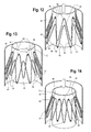
Figure 12 is an enlarged view of the proximal end of a leg extension being inserted in a proximal direction into the distal end of the main body stent graft and before the respective locking stents are engaged; -
Figure 13 illustrates the leg extension being rotated relative to the main body stent graft to align the respective locking stents for interlocking engagement; -
Figure 14 illustrates the leg extension being pulled distally after the respective locking stents have been properly aligned for interlocking engagement; and -
Figure 15 illustrates one example of an introducer for delivery and deployment of one or more of the modular stent graft components. - Throughout this specification, the terms proximal and proximally are used to refer to a position or direction towards the patient and/or to be inserted into a patient's body orifices or cavities and the terms distal and distally are used to refer to a position or direction away from, or even external to a patient's body. While the description below is directed to endovascular prostheses used within the abdominal aorta and iliac arteries for treatment of aortic aneurysm, use in any other body lumens and/or vessels, for example, the thoracic aorta and/or branch or peripheral vessels, the gastrointestinal tract, ducts and orifices is also contemplated.
- Now looking more closely at the drawings and more particularly
Figure 2 , a schematic view of the vasculature of a patient is illustrated, particularly showing the aorta and aortic bifurcation extending down towards the iliac arteries. The vasculature comprises anaorta 10 in the region between therenal arteries 12 and theaortic bifurcation 14.Common iliac arteries aortic bifurcation 14. Thecommon iliac arteries internal iliac arteries external iliac arteries aorta 10 is shown as having ananeurysm 28 which extends towards theaortic bifurcation 14. - To traverse the
aneurysm 28, a bifurcatedaortic stent graft 30 has been deployed into theaorta 10. The bifurcatedaortic stent graft 30 comprises a maintubular body 32 of a biocompatible graft material. Examples of biocompatible graft materials include polyesters, such as poly(ethylene terephthalate), and fluorinated polymers, such as polytetrafluoroethylene (PTFE) and expanded PTFE. Examples of biocompatible polyesters include DACRON (DUPONT, Wilmington, Del.) and TWILLWEAVE MICREL (VASCUTEK, Renfrewshire, Scotland). Other examples of biocompatible materials include extracellular matrix (ECM) materials, such as a purified collagen-based matrix derived from submucosa tissue. The graft material may be made of a single material, or it may be a blend, weave, laminate or composite of two or more materials. The graft material may also include other additives, such as plasticizers, compatibilizers, surface modifiers, biological materials such as peptides and enzymes, and therapeutic agents such as drugs or other medicaments. The particular graft material on any one portion of the graft may be the same, or the materials may be different. Thebifurcated stent graft 30 has ashort leg 34 and along leg 36 extending from abifurcation 38. One example of a bifurcated stent graft includes the Zenith LP stent graft available from COOK, INC. (Bloomington, Ind.). - The
graft material 32 is secured to and supported by one ormore stents 40. For example, standardsurgical suturing techniques 42 can be used to secure thegraft material 32 to astent 40. Astent 40 can be positioned on the interior of the tubular graft material, or it can be positioned on the exterior of the graft material as shown inFigures 1 and 2 . In another example, a stent can be sandwiched between two layers of graft material, and this stent may also be secured bysutures 42. - The
stents 40 may have a wide variety of configurations and may be balloon expandable or self-expanding. Typically, stents have a circular or cylindrical cross-section when fully expanded, so as to conform to the generally circular cross-section of a body lumen. For example, the stents may be discrete stents having a zig-zag configuration in which straight struts 44 are set at angles to each other and are connected by acute bends orapices 46. The struts are thus connected into an endless loop, forming a generally tubular structure as shown inFigures 1 and 2 . Discrete zig-zag stents are also referred to as Gianturco stents or Z-stents such as the Z-STENT available from COOK, INC. (Bloomington, Ind.). In another example, the stents may contain individual stent segments that are connected to provide an elongated, flexible stent. The individual stent segments can have a variety of configurations, including the zig-zag configuration. A specific example of a connected zig-zag stent is the ZILVER™ stent also available from COOK, INC. -
Stents 40 may be made of any rigid biocompatible material, such as metal, plastic or ceramic. Preferably the stents are made of a metal, such as stainless steel, nitinol, and other biocompatible alloys. Stents may be equipped with one or more barbs to secure the prosthesis to the vessel wall or to another component of the prosthesis. If thestent 40 is secured to thegraft material 32 by suturing, thesutures 42 may be positioned alongstruts 44 and/or at the bends orapices 46 of thestent 40. For stents having a zig-zag configuration, it may be desirable to employ a suture at least one of theapices 46, or alternatively, asuture 42 at each apex 46 of thestent 40 to further increase the stability of the connection. Thestents 40 illustrated inFigures 1 and 2 are preferably manufactured from a shape memory alloy, including, for example, nitinol, such that it can be loaded on to a delivery device in a radially compressed configuration which then self-expands upon deployment within the vasculature of a patient as shown inFigure 2 . - Turning back now to
Figure 2 , theproximal end 48 of thebifurcated stent graft 30 is engaged with a non-aneurysed portion of theaorta 10 just distal of therenal arteries 12. To ensure good fixation thestent graft 30 includes, in one non-limiting example, a supra renal exposedstent 50 withbarbs 52 engaging the wall of theaorta 10 proximal of therenal arteries 12. It is also contemplated, however, that other known methods of fixation may be utilized to secure thestent 30 in a desired location within the vasculature, and more particularly, to secure theproximal end 48 of theaortic stent graft 30 within theaorta 10. - As
Figures 1 and 2 illustrate,stents 40 have been shown as external stents which are sutured to the external surface of the main body of thegraft 32. Furthermore, one or more stents are secured the graft material along the lengths of both theshort leg 34 andlong leg 36. More specifically,short leg 34 andlong leg 36 have one or more longitudinally spacedstents 54. As shown,short leg 34 has oneexternal stent 54 distal of thebifurcation 38 followed by oneinternal stent 56 and then anotherexternal stent 54 at the distalmost end 58 of theshort leg 34.Long leg 36 is shown as having threeexternal stents 54 distal of thebifurcation 38 followed by oneinternal stent 60 and anotherexternal stent 54 at the distalmost end 62 of thelong leg 36. Thestents 54 secured to the short andlong legs internal stents legs - More specifically, the
internal stents distal end short leg 34 andlong leg 36 may, in one example, may be flared or formed into a frusto-conical configuration thus forming an internal connection or "locking stent" which may provide for enhanced sealing and attachment between the respective first andsecond legs internal locking stent 56 onshort leg 34 is preferably substantially similar in shape and configuration tointernal locking stent 60 onlong leg 36, thus the description of internal lockingstent 56 similarly applies tointernal locking stent 60 unless otherwise noted.Internal stent 56 preferably comprisesstruts 64 andproximal apices 66 anddistal apices 68 between thestruts 64. In one example, theinternal locking stent 56 may be made by conventional manufacturing process such that it is initially a cylindrical shape and then formed into a frusto-conical cone shape such as by heat treatment.Internal stent 56 may be secured to the graft material oflegs 34 and/or 36 by asuture 42 or similar attachment means at one or more of thedistal stent apices 68 such that it flares radially inwardly from the suture/graft attachment point 42 in a proximal direction. In other words, theinternal locking stent 56 may be "cone shaped" with one or more of thedistal-most apices 68 being sutured to the graft and forming the widest diameter D2 and theproximal-most stent apices 66 being flared radially inwardly therefrom (thus having the narrowest diameter D1 at the proximal apices 66). WhileFigure 3 shows all of theproximal stent apices 66 being flared radially inwardly to form a frusto-conical configuration, it is also contemplated that only selectedapices 66 are flared inwardly. For example, only onestent apex 66, or a pair of apices 66 (whether adjacent apices, alternating apices or opposing apices) may be inwardly flared, while the remaining "non-flared" apices retain a substantially cylindrical shape. - As shown in
Figure 2 theshort leg 34 of the bifurcatedaortic stent graft 30, may not extend distally down to or much beyond theaortic bifurcation 14. Therefore, an iliacleg extension piece 70 may be provided for connection to theshort leg 34. The externalproximal sealing surface 72 of the iliacleg extension piece 70 is configured to provide an interface to seal within the lumen of theshort leg 34 of thebifurcated stent graft 30 while thedistal end 74 of the iliacleg extension piece 70 may engage in a sealing manner into a non-aneurysed, healthy portion of the commoniliac artery 16 and/or externaliliac artery 24. - In the case where an aneurysm extends down into the external
iliac artery 24, the iliacleg extension piece 70 may serve as a bridge which extends between theshort leg 34 of the bifurcatedaortic stent graft 30 and the proximal end of another stent graft component, i.e., a branched iliac stent graft (not shown). Such a branched iliac stent graft would extend distally beyond any such aneurysm so that its distal end may engage in a sealing manner with a non-aneurysed portion of the externaliliac artery 24. -
Figure 2 illustrates thelong leg 36 of thebifurcated stent graft 30 extending distally into the commoniliac artery 18, such that thedistal end 62 oflong leg 36 is engaged with a healthy, non-aneurysed portion of commoniliac artery 18. However, if necessary or desired (such as in the event that an aneurysm extends down into the commoniliac artery 18 distally of thelong leg 36 and/or into the external iliac artery 26), then another iliac extension piece (not shown) like that of iliacleg extension piece 70 may be provided that sealingly connects to thelong leg 36 of thestent graft 30 for extending distally into the commoniliac artery 18, or even further into the externaliliac artery 26. Thus, description of iliacleg extension piece 70 that sealingly connects toshort leg 34 may similarly apply to any additional leg extension piece that is attached tolong leg 36. - One example of iliac
leg extension piece 70 is illustrated in further detail inFigure 1 . As shown there, iliacleg extension piece 70 is preferably a tubular body of biocompatible graft material. One ormore stents 76 are secured to the graft material along the length ofleg extension 70. It is noted that leg extension piece 70 (or any additional leg extension piece that is attached to long leg 36) can be of a variety of dimensions (i.e., varying lengths and/or widths) depending upon the requirements of a particular situation, the geometry of a patient's vasculature and the location of deployment. Hence, the number ofstents 76 along the length of the tubular body ofleg extension 70 can vary. There may be one, two or more self-expandingstents 76 that are located on the inside and/or on the outside of the tubular graft material. In one example, the stents are preferably self-expanding Z-stents having a zig-zag configuration in which straight struts 78 are set at angles to each other and are connected by acute bends orapices - As shown in
Figures 1 and 2 , thestents 76 secured to the graft material ofleg extension 70 are generally cylindrical in nature, with the exception ofexternal stent 84.External stent 84 secured near theproximal end 72 ofleg extension 70 may, in one example, be flared such that it is frusto-conical or cone-shaped, thus forming a connection or locking stent. Lockingstent 84 is configured to lock with or otherwise connect to the correspondingly configured frusto-conical locking stent 56 within the lumen ofshort leg 34 as described in further detail below. - More particularly, the frusto-conical external locking
stent 84 may be secured to the graft material ofleg extension 70 by asuture 42 or similar attachment means, at one or more of theproximal stent apices 80, and flare radially outwardly therefrom in a distal direction. In other words, the stent may be "cone shaped" with one or more of the mostproximal apices 80 being sutured to the graft (and having the narrowest diameter D3) and thedistal-most stent apices 82 being flared radially outwardly (and having the widest diameter D4). WhileFigure 3 shows all of the distallocking stent apices 82 being flared radially outwardly, it is also contemplated that only selectedapices 82 are flared outwardly. For example, only onestent apex 82, or a pair of apices 82 (whether adjacent apices, alternating apices or opposing apices) may be outwardly flared, while the remaining "non-flared" apices retain a substantially cylindrical shape. - The
proximal end 72 of theleg extension 70 extends at least partially into the lumen of theshort leg 34 such that an overlap or interface exists between thedistal end 58 ofshort leg 34 and theproximal end 72 ofleg extension 70. Theleg extension 70 may then be locked into place when the internal flared lockingstent 56 near thedistal end 58 ofshort leg 34 engages the external flared lockingstent 84 near theproximal end 72 ofleg extension 70, as described in further detail below. - In one non-limiting example of use, the main
bifurcated stent graft 30 can be delivered and deployed within a patient'saorta 10 andleg extension 70 sealingly connected to short leg 34 (and any additional leg extension sealingly connected tolong leg 36 if necessary and desired) as follows. First, a main graft such as the bifurcatedaortic stent graft 30 can first be delivered to a treatment site using a variety of endovascular techniques. In treating aortic aneurysms, a catheter-based introducer, such as those available from COOK, INC. (Bloomington, Ind.) can be used to insert a compressed endovascular prosthesis (such as stent graft 30) into the body through a femoral artery and then into theaorta 10. - Referring to
Figure 15 , one example of anintroducer 200 for the bifurcatedaortic stent graft 30 may include adelivery sheath 202 surroundingstent graft 30 which is carried by tapereddilator 204 atproximal end 206, and a fitting 208 atdistal end 210 of the delivery system.Inner cannula 214, which is connected to handle 216, extends from the tapereddilator 204 todistal end 210. Theintroducer 200 may also include check-flow valve 226,pusher 228, pusher fitting 230 andpin vise 232. Once the introducer has been inserted into the patient's vasculature and theaortic stent graft 30 positioned in its desired location, thedelivery sheath 202 can then be pulled back towards thedistal end 210 of thedelivery system 200 and any diameter-reducing ties removed so that thestent graft 30 is deployed within theaorta 10. Commonly, thelonger leg 36 is deployed in the ipsilateral iliac artery and theshorter leg 34 deployed in the contralateral iliac artery, with thebifurcation 38 ofstent graft 30 seated adjacent to theaortic bifurcation 14. - With the bifurcated
aortic stent graft 30 deployed and in place in theaorta 10, an iliacleg extension piece 70 may then be delivered to a treatment site, such asiliac artery 16 illustrated inFigure 2 , using a variety of known endovascular techniques. For example, another catheter basedintroducer 200 may be used to insert a compressed prosthesis such asleg extension 70 into the vasculature so that theproximal end 72 ofleg extension 70 is located within the lumen ofshort leg 34. Preferably, the internal flared lockingstent 56 near thedistal end 58 ofshort leg 34 is aligned with the external flared lockingstent 84 near theproximal end 72 ofleg extension 70. Radiopaque markers or other indicators may be used to facilitate proper placement and alignment ofleg extension 70 withshort leg 34. In one example, theproximal end 72 ofleg extension 70 can initially be moved in a proximal direction within the lumen ofshort leg 34 so that the external flared lockingstent 84 ofleg extension 70 moves beyond (i.e., proximally past) the internal flared lockingstent 56 ofshort leg 34 as shown inFigures 4, 6 and12 . Thesheath 202 covering theleg extension 70 on the delivery device may then be withdrawn so that leg extension at least partially radially outwardly expands within the lumen ofshort leg 34. - The physician may then pull back slightly on the
leg extension 70 in a distal direction as shown inFigure 10 andFigure 14 until the internal flared lockingstent 56 near thedistal end 58 ofshort leg 34 engages and/or otherwise locks with the external flared lockingstent 84 near theproximal end 72 ofleg extension 70. Locking may be determined in various ways, such as, for example, the physician sensing resistance when pulling distally on theleg extension 70. In other words, when locking occurs, the outwardly flareddistal apices 82 of the lockingstent 84 onleg extension 70 become nested and securely braced between the graft material ofshort leg 34 and the inwardly flaredproximal apices 66 of the lockingstent 56 ofshort leg 34 as shown inFigures 10, 11 and14 . - If the respective two locking
stents leg extension 70 may be at least partially pulled back into thesheath 202 and the introducer rotated in one or more small increments as shown inFigures 8 and13 and theleg extension 70 redeployed until proper alignment of the respective lockingstents Figures 10, 11 and - 14. In order for the locking stents to become "unlocked," the
leg extension 70 must be pushed proximally at least until thedistal apices 82 of the lockingstent 84 onleg extension 70 have moved proximally away from and beyond theproximal apices 66 of lockingstent 56 inshort leg 34, thus allowing the two lockingstents - If necessary or desired, the delivery and deployment of an additional iliac leg extension, such as a leg extension for connection to
long leg 36, may be accomplished in a manner similar to that described above. For example, an additional leg extension may be delivered to a treatment site (such as iliac artery 18) by adelivery catheter 200 and the proximal end of the additional leg extension positioned within the lumen oflong leg 36. Anexternal locking stent 84 on the proximal end of such an additional leg extension may then engage and lock with aninternal locking stent 60 withinlong leg 36, thus providing a secure connection between the respective stent grafts. - With the main
bifurcated graft 30 and one or moreiliac leg extensions 70 connected to one or both ofshort leg 34 and/orlong leg 36, delivery of the complete modular endovascular prosthesis is accomplished. As is evident inFigure 2 , there is overlap where the graft material at theproximal end 72 ofiliac leg extension 70 interfaces with theshort leg 34 when theleg extension 70 has been deployed. The stents at theproximal end 72 ofiliac leg extension 70 self-expand, thereby pressing against the inner surface of the lumen of theshort leg 34 of thebifurcated prosthesis 30. This overlap of graft material establishes a friction fit connection between the twostent graft components legs bifurcated prosthesis 30 at the implantation site is further enhanced by the locking engagement between the respective lockingstents respective components body stent graft 30 and theleg extensions 70. - While the description above describes the locking
stent 84 onleg extension 70 to be an external stent and the lockingstent 56 withinshort leg 34 to be an internal stent, it is also contemplated that any of the stent placements may be reversed and relocated. In one non-limiting example, one or more internal stents within the lumen ofleg extension 70 may be arranged to engage and lock with one or more external stents on eithershort leg 34 orlong leg 36. - Throughout this specification, unless the context requires otherwise, the words "comprise" and "include" and variations such as "comprising" and "including" will be understood to imply the inclusion of an item or group of items, but not the exclusion of any other item or group items.
- While various embodiments of the invention have been described, it will be apparent to those of ordinary skill in the art that many more embodiments and implementations are possible within the scope of the invention. Furthermore, although various indications have been given as to the scope of this invention, the invention is not limited to any one of these but may reside in two or more of these combined together. Accordingly, the invention is not to be restricted except in light of the attached claims and their equivalents.
- The disclosures in United States
patent application number 14/180,637
Claims (13)
- A modular stent graft system including:a first stent graft including a first tubular body of biocompatible graft material, a proximal end, a distal end and a first interface region having an internal surface and an external surface at the distal end;a first self-expanding locking stent secured to the internal surface of the first interface region, the first locking stent including a series of proximal apices and a series of distal apices, a proximal end having a first diameter and a distal end having a second diameter greater than the first diameter, wherein the first locking stent is secured to the internal surface of the first interface region only at the distal stent apices;a second stent graft including a second tubular body of biocompatible graft material, a proximal end, a distal end and a second interface region having an internal surface and an external surface at the proximal end configured to at least partially overlap with the first interface region;a second self-expanding locking stent secured to the external surface of the second interface region, the second locking stent including a series of proximal apices, a series of distal apices, a proximal end having a first diameter and a distal end having a second diameter greater than the first diameter, wherein the second locking stent is secured to the external surface of the second interface region only at the proximal stent apices;wherein the first locking stent is configured to receive the second locking stent in an interlocking relationship.
- A stent graft system according to claim 1, wherein at least a portion of the second locking stent is nested between the first locking stent and the internal surface of the interface region of the first stent graft when the first and second locking stents are interlocked.
- A stent graft system according to claim 1 or 2, wherein the proximal end of the second stent graft is sealingly engaged with the distal end of the first stent graft when the first and second locking stents are interlocked.
- A stent graft system according to claim 1, 2 or 3, wherein the proximal apices of the first locking stent are proximal to and circumferentially aligned with the distal apices of the second locking stent when the first and second locking stents are interlocked.
- A stent graft system according to any preceding claim, wherein the second stent graft includes a leg extension stent graft configured for placement in the iliac artery.
- A stent graft system according to any preceding claim, wherein the first stent graft includes a bifurcated stent graft configured for placement in the abdominal aorta.
- A stent graft system according to any preceding claim, wherein the distal end of the first stent graft is bifurcated and includes a first leg and a second leg.
- A stent graft system according to claim 7, wherein the first locking stent is secured to at least one of the first and second leg.
- A stent graft system according to claim 8, wherein a third locking stent is secured to the other of the first and second leg.
- A stent graft system according to claim 9, including a third stent graft including a third tubular body of biocompatible graft material, a proximal end, a distal end and a third interface region having an internal surface and an external surface at the proximal end;
a fourth self-expanding locking stent secured to the external surface of the third interface region, the fourth locking stent including a series of proximal apices, a series of distal apices, a proximal end having a first diameter and a distal end having a second diameter greater than the first diameter, wherein the fourth locking stent is secured to the external surface of the third interface region only at the proximal stent apices; and
wherein the third locking stent is configured to receive the fourth locking stent in an interlocking relationship. - A method of assembling a modular stent graft system, including the steps of:providing a first stent graft including a first tubular body of biocompatible graft material, a proximal end, a distal end and a first interface region having an internal surface and an external surface at the distal end; a first self-expanding locking stent secured to the internal surface of the first interface region, the first locking stent including a series of proximal apices and a series of distal apices, a proximal end having a first diameter and a distal end having a second diameter greater than the first diameter, wherein the first locking stent is secured to the internal surface of the first interface region only at the distal stent apices;providing a second stent graft including a second tubular body of biocompatible graft material, a proximal end, a distal end and a second interface region having an internal surface and an external surface at the proximal end configured to at least partially overlap with the first interface region; a second self-expanding locking stent secured to the external surface of the second interface region, the second locking stent comprising a series of proximal apices, a series of distal apices, a proximal end having a first diameter and a distal end having a second diameter greater than the first diameter, wherein the second locking stent is secured to the external surface of the second interface region only at the proximal stent apices;inserting at least a portion of the proximal end of the second stent graft into the distal end of the first stent graft so that the first and second interface regions at least partially overlap;allowing the second stent graft to expand;interlocking the first and second locking stents such that the distal apices of the second locking stent are nested between the first locking stent and the internal surface of the interface region of the first stent graft.
- A method according to claim 11, including the step of rotating the first and second stent grafts with respect to each other until the proximal apices of the first locking stent are circumferentially aligned with the distal apices of the second locking stent prior to the step of interlocking.
- A method according to claim 11 or 12, wherein the first and second stent grafts are interlocked when the first and second locking stents are engaged.
Priority Applications (1)
| Application Number | Priority Date | Filing Date | Title |
|---|---|---|---|
| EP20181220.3A EP3733128A1 (en) | 2014-02-14 | 2015-02-11 | Locking mechanism for securing the interface between stent grafts |
Applications Claiming Priority (1)
| Application Number | Priority Date | Filing Date | Title |
|---|---|---|---|
| US14/180,637 US9161831B2 (en) | 2014-02-14 | 2014-02-14 | Locking mechanism for securing the interface between stent grafts |
Related Child Applications (2)
| Application Number | Title | Priority Date | Filing Date |
|---|---|---|---|
| EP20181220.3A Division EP3733128A1 (en) | 2014-02-14 | 2015-02-11 | Locking mechanism for securing the interface between stent grafts |
| EP20181220.3A Division-Into EP3733128A1 (en) | 2014-02-14 | 2015-02-11 | Locking mechanism for securing the interface between stent grafts |
Publications (2)
| Publication Number | Publication Date |
|---|---|
| EP2907478A1 true EP2907478A1 (en) | 2015-08-19 |
| EP2907478B1 EP2907478B1 (en) | 2020-08-05 |
Family
ID=52468956
Family Applications (2)
| Application Number | Title | Priority Date | Filing Date |
|---|---|---|---|
| EP20181220.3A Pending EP3733128A1 (en) | 2014-02-14 | 2015-02-11 | Locking mechanism for securing the interface between stent grafts |
| EP15275031.1A Active EP2907478B1 (en) | 2014-02-14 | 2015-02-11 | Locking mechanism for securing the interface between stent grafts |
Family Applications Before (1)
| Application Number | Title | Priority Date | Filing Date |
|---|---|---|---|
| EP20181220.3A Pending EP3733128A1 (en) | 2014-02-14 | 2015-02-11 | Locking mechanism for securing the interface between stent grafts |
Country Status (2)
| Country | Link |
|---|---|
| US (2) | US9161831B2 (en) |
| EP (2) | EP3733128A1 (en) |
Cited By (3)
| Publication number | Priority date | Publication date | Assignee | Title |
|---|---|---|---|---|
| CN106344209A (en) * | 2016-10-11 | 2017-01-25 | 有研医疗器械(北京)有限公司 | Abdominal aorta covered stent and conveying device thereof and using method |
| CN111789703A (en) * | 2020-08-07 | 2020-10-20 | 上海恩盛医疗科技有限公司 | Modular-based vascular stent construction method |
| EP3988051A4 (en) * | 2019-06-19 | 2023-07-05 | SB-Kawasumi Laboratories, Inc. | STEN IMPLANT |
Families Citing this family (15)
| Publication number | Priority date | Publication date | Assignee | Title |
|---|---|---|---|---|
| JP6416687B2 (en) * | 2015-04-17 | 2018-10-31 | 株式会社ジャパンディスプレイ | Display device and touch detection device |
| CN109077836B (en) * | 2015-12-30 | 2021-01-22 | 先健科技(深圳)有限公司 | Lumen stent |
| CN107822739B (en) * | 2016-09-07 | 2020-03-24 | 先健科技(深圳)有限公司 | Lumen Stents and Lumen Stent Systems |
| CN106580518B (en) * | 2016-12-20 | 2018-11-16 | 有研医疗器械(北京)有限公司 | A kind of combined type endovascular stent for abdominal aorta system and its application method |
| JP2021013405A (en) * | 2017-11-22 | 2021-02-12 | 川澄化学工業株式会社 | Intravascular detention tool coupling structure and intravascular detention system |
| JPWO2020045315A1 (en) * | 2018-08-30 | 2021-08-12 | 川澄化学工業株式会社 | Gastrointestinal stent |
| US11406540B2 (en) * | 2018-09-05 | 2022-08-09 | Acclarent, Inc. | Linked assembly with isthmus anchor for treating patulous eustachian tube |
| CN114206261B (en) * | 2019-06-25 | 2026-04-14 | 阿特利姆医疗公司 | Stent device including expandable crowns |
| CN112386365A (en) * | 2019-08-12 | 2021-02-23 | 新光医疗财团法人新光吴火狮纪念医院 | Tectorial membrane support for central vein |
| JP7408773B2 (en) * | 2019-08-21 | 2024-01-05 | ボストン サイエンティフィック サイムド,インコーポレイテッド | Circulation auxiliary pump fixing and centering device |
| CN114929162A (en) | 2019-10-24 | 2022-08-19 | 阿特利姆医疗公司 | Intravascular fixing device |
| RU2742451C1 (en) * | 2020-03-04 | 2021-02-05 | Заза Александрович Кавтеладзе | Bifurcation stent-graft system for treating aneurism of abdominal aorta and method of treating aneurism of abdominal aorta using thereof |
| WO2024220501A1 (en) * | 2023-04-17 | 2024-10-24 | Vascudyne, Inc. | External support for a tissue implant |
| CN116602804A (en) * | 2023-07-17 | 2023-08-18 | 浙江归创医疗科技有限公司 | Abdominal aorta tectorial membrane stent system |
| GB2634709A (en) * | 2023-10-02 | 2025-04-23 | Otsuka Medical Devices Co Ltd | Stents |
Citations (6)
| Publication number | Priority date | Publication date | Assignee | Title |
|---|---|---|---|---|
| WO1998053761A1 (en) | 1997-05-26 | 1998-12-03 | William A. Cook Australia Pty. Ltd. | A prosthesis and a method and means of deploying a prosthesis |
| WO2004016193A2 (en) * | 2002-08-16 | 2004-02-26 | Endovascular Technologies, Inc. | Lock modular graft component junctions |
| US20040225349A1 (en) * | 2003-05-09 | 2004-11-11 | Thistle Robert C. | Eversible locking mechanism for modular stents |
| US20060178733A1 (en) * | 2005-01-21 | 2006-08-10 | Leonard Pinchuk | Modular stent graft employing bifurcated graft and leg locking stent elements |
| US7160318B2 (en) | 2001-03-28 | 2007-01-09 | Cook Incorporated | Modular stent graft assembly and use thereof |
| US20090270971A1 (en) * | 2008-04-24 | 2009-10-29 | Medtronic Vascular, Inc. | Prosthesis Fixation Apparatus and Methods |
Family Cites Families (4)
| Publication number | Priority date | Publication date | Assignee | Title |
|---|---|---|---|---|
| US5741293A (en) | 1995-11-28 | 1998-04-21 | Wijay; Bandula | Locking stent |
| US7226474B2 (en) | 2000-05-01 | 2007-06-05 | Endovascular Technologies, Inc. | Modular graft component junctions |
| US7135037B1 (en) * | 2000-05-01 | 2006-11-14 | Endovascular Technologies, Inc. | System and method for forming a junction between elements of a modular endovascular prosthesis |
| US7637932B2 (en) * | 2001-11-28 | 2009-12-29 | Aptus Endosystems, Inc. | Devices, systems, and methods for prosthesis delivery and implantation |
-
2014
- 2014-02-14 US US14/180,637 patent/US9161831B2/en active Active
-
2015
- 2015-02-11 EP EP20181220.3A patent/EP3733128A1/en active Pending
- 2015-02-11 EP EP15275031.1A patent/EP2907478B1/en active Active
- 2015-10-07 US US14/877,580 patent/US9687337B2/en active Active
Patent Citations (6)
| Publication number | Priority date | Publication date | Assignee | Title |
|---|---|---|---|---|
| WO1998053761A1 (en) | 1997-05-26 | 1998-12-03 | William A. Cook Australia Pty. Ltd. | A prosthesis and a method and means of deploying a prosthesis |
| US7160318B2 (en) | 2001-03-28 | 2007-01-09 | Cook Incorporated | Modular stent graft assembly and use thereof |
| WO2004016193A2 (en) * | 2002-08-16 | 2004-02-26 | Endovascular Technologies, Inc. | Lock modular graft component junctions |
| US20040225349A1 (en) * | 2003-05-09 | 2004-11-11 | Thistle Robert C. | Eversible locking mechanism for modular stents |
| US20060178733A1 (en) * | 2005-01-21 | 2006-08-10 | Leonard Pinchuk | Modular stent graft employing bifurcated graft and leg locking stent elements |
| US20090270971A1 (en) * | 2008-04-24 | 2009-10-29 | Medtronic Vascular, Inc. | Prosthesis Fixation Apparatus and Methods |
Cited By (5)
| Publication number | Priority date | Publication date | Assignee | Title |
|---|---|---|---|---|
| CN106344209A (en) * | 2016-10-11 | 2017-01-25 | 有研医疗器械(北京)有限公司 | Abdominal aorta covered stent and conveying device thereof and using method |
| CN106344209B (en) * | 2016-10-11 | 2018-11-20 | 有研医疗器械(北京)有限公司 | A kind of endovascular stent for abdominal aorta and its conveying device and application method |
| EP3988051A4 (en) * | 2019-06-19 | 2023-07-05 | SB-Kawasumi Laboratories, Inc. | STEN IMPLANT |
| CN111789703A (en) * | 2020-08-07 | 2020-10-20 | 上海恩盛医疗科技有限公司 | Modular-based vascular stent construction method |
| CN111789703B (en) * | 2020-08-07 | 2021-09-28 | 上海恩盛医疗科技有限公司 | Blood vessel stent construction method based on modularization |
Also Published As
| Publication number | Publication date |
|---|---|
| EP3733128A1 (en) | 2020-11-04 |
| EP2907478B1 (en) | 2020-08-05 |
| US20160022413A1 (en) | 2016-01-28 |
| US9687337B2 (en) | 2017-06-27 |
| US9161831B2 (en) | 2015-10-20 |
| US20150230915A1 (en) | 2015-08-20 |
Similar Documents
| Publication | Publication Date | Title |
|---|---|---|
| EP2907478B1 (en) | Locking mechanism for securing the interface between stent grafts | |
| US7674284B2 (en) | Endoluminal graft | |
| JP4464972B2 (en) | Interconnected leg extensions for endoluminal prostheses | |
| US8002816B2 (en) | Prosthesis for implantation in aorta and method of using same | |
| US8043363B2 (en) | Endoluminal prosthesis | |
| EP2007313B1 (en) | Stent graft | |
| EP1684668B1 (en) | Aorta and branch vessel stent grafts and system | |
| US10265202B2 (en) | Prosthesis having an everting pivoting fenestration | |
| US20190231571A1 (en) | Delivery System And Method To Radially Constrict A Stent Graft | |
| EP2985007B1 (en) | Preloaded wire for endoluminal device | |
| US20120172965A1 (en) | Conformable prosthesis delivery system and method for deployment thereof | |
| US20110313512A1 (en) | Side Branch Stent Graft | |
| EP3446656B1 (en) | Introducer including a stent graft adaptor | |
| US20180021155A1 (en) | Tapered body aaa graft | |
| EP2749249B1 (en) | Endoluminal prosthesis | |
| EP2702960B1 (en) | Endoluminal prosthesis and delivery device |
Legal Events
| Date | Code | Title | Description |
|---|---|---|---|
| PUAI | Public reference made under article 153(3) epc to a published international application that has entered the european phase |
Free format text: ORIGINAL CODE: 0009012 |
|
| AK | Designated contracting states |
Kind code of ref document: A1 Designated state(s): AL AT BE BG CH CY CZ DE DK EE ES FI FR GB GR HR HU IE IS IT LI LT LU LV MC MK MT NL NO PL PT RO RS SE SI SK SM TR |
|
| AX | Request for extension of the european patent |
Extension state: BA ME |
|
| 17P | Request for examination filed |
Effective date: 20160215 |
|
| RBV | Designated contracting states (corrected) |
Designated state(s): AL AT BE BG CH CY CZ DE DK EE ES FI FR GB GR HR HU IE IS IT LI LT LU LV MC MK MT NL NO PL PT RO RS SE SI SK SM TR |
|
| STAA | Information on the status of an ep patent application or granted ep patent |
Free format text: STATUS: EXAMINATION IS IN PROGRESS |
|
| 17Q | First examination report despatched |
Effective date: 20180720 |
|
| GRAP | Despatch of communication of intention to grant a patent |
Free format text: ORIGINAL CODE: EPIDOSNIGR1 |
|
| STAA | Information on the status of an ep patent application or granted ep patent |
Free format text: STATUS: GRANT OF PATENT IS INTENDED |
|
| RIC1 | Information provided on ipc code assigned before grant |
Ipc: A61F 2/852 20130101ALN20200131BHEP Ipc: A61F 2/07 20130101AFI20200131BHEP |
|
| INTG | Intention to grant announced |
Effective date: 20200226 |
|
| RIN1 | Information on inventor provided before grant (corrected) |
Inventor name: FARAG, JACQUELINE |
|
| GRAS | Grant fee paid |
Free format text: ORIGINAL CODE: EPIDOSNIGR3 |
|
| GRAA | (expected) grant |
Free format text: ORIGINAL CODE: 0009210 |
|
| STAA | Information on the status of an ep patent application or granted ep patent |
Free format text: STATUS: THE PATENT HAS BEEN GRANTED |
|
| AK | Designated contracting states |
Kind code of ref document: B1 Designated state(s): AL AT BE BG CH CY CZ DE DK EE ES FI FR GB GR HR HU IE IS IT LI LT LU LV MC MK MT NL NO PL PT RO RS SE SI SK SM TR |
|
| REG | Reference to a national code |
Ref country code: GB Ref legal event code: FG4D |
|
| REG | Reference to a national code |
Ref country code: CH Ref legal event code: EP |
|
| REG | Reference to a national code |
Ref country code: AT Ref legal event code: REF Ref document number: 1297655 Country of ref document: AT Kind code of ref document: T Effective date: 20200815 |
|
| REG | Reference to a national code |
Ref country code: DE Ref legal event code: R096 Ref document number: 602015056845 Country of ref document: DE |
|
| REG | Reference to a national code |
Ref country code: IE Ref legal event code: FG4D |
|
| REG | Reference to a national code |
Ref country code: LT Ref legal event code: MG4D |
|
| REG | Reference to a national code |
Ref country code: NL Ref legal event code: MP Effective date: 20200805 |
|
| REG | Reference to a national code |
Ref country code: AT Ref legal event code: MK05 Ref document number: 1297655 Country of ref document: AT Kind code of ref document: T Effective date: 20200805 |
|
| PG25 | Lapsed in a contracting state [announced via postgrant information from national office to epo] |
Ref country code: ES Free format text: LAPSE BECAUSE OF FAILURE TO SUBMIT A TRANSLATION OF THE DESCRIPTION OR TO PAY THE FEE WITHIN THE PRESCRIBED TIME-LIMIT Effective date: 20200805 Ref country code: BG Free format text: LAPSE BECAUSE OF FAILURE TO SUBMIT A TRANSLATION OF THE DESCRIPTION OR TO PAY THE FEE WITHIN THE PRESCRIBED TIME-LIMIT Effective date: 20201105 Ref country code: PT Free format text: LAPSE BECAUSE OF FAILURE TO SUBMIT A TRANSLATION OF THE DESCRIPTION OR TO PAY THE FEE WITHIN THE PRESCRIBED TIME-LIMIT Effective date: 20201207 Ref country code: FI Free format text: LAPSE BECAUSE OF FAILURE TO SUBMIT A TRANSLATION OF THE DESCRIPTION OR TO PAY THE FEE WITHIN THE PRESCRIBED TIME-LIMIT Effective date: 20200805 Ref country code: SE Free format text: LAPSE BECAUSE OF FAILURE TO SUBMIT A TRANSLATION OF THE DESCRIPTION OR TO PAY THE FEE WITHIN THE PRESCRIBED TIME-LIMIT Effective date: 20200805 Ref country code: NO Free format text: LAPSE BECAUSE OF FAILURE TO SUBMIT A TRANSLATION OF THE DESCRIPTION OR TO PAY THE FEE WITHIN THE PRESCRIBED TIME-LIMIT Effective date: 20201105 Ref country code: GR Free format text: LAPSE BECAUSE OF FAILURE TO SUBMIT A TRANSLATION OF THE DESCRIPTION OR TO PAY THE FEE WITHIN THE PRESCRIBED TIME-LIMIT Effective date: 20201106 Ref country code: AT Free format text: LAPSE BECAUSE OF FAILURE TO SUBMIT A TRANSLATION OF THE DESCRIPTION OR TO PAY THE FEE WITHIN THE PRESCRIBED TIME-LIMIT Effective date: 20200805 Ref country code: HR Free format text: LAPSE BECAUSE OF FAILURE TO SUBMIT A TRANSLATION OF THE DESCRIPTION OR TO PAY THE FEE WITHIN THE PRESCRIBED TIME-LIMIT Effective date: 20200805 Ref country code: LT Free format text: LAPSE BECAUSE OF FAILURE TO SUBMIT A TRANSLATION OF THE DESCRIPTION OR TO PAY THE FEE WITHIN THE PRESCRIBED TIME-LIMIT Effective date: 20200805 |
|
| PG25 | Lapsed in a contracting state [announced via postgrant information from national office to epo] |
Ref country code: IS Free format text: LAPSE BECAUSE OF FAILURE TO SUBMIT A TRANSLATION OF THE DESCRIPTION OR TO PAY THE FEE WITHIN THE PRESCRIBED TIME-LIMIT Effective date: 20201205 Ref country code: LV Free format text: LAPSE BECAUSE OF FAILURE TO SUBMIT A TRANSLATION OF THE DESCRIPTION OR TO PAY THE FEE WITHIN THE PRESCRIBED TIME-LIMIT Effective date: 20200805 Ref country code: NL Free format text: LAPSE BECAUSE OF FAILURE TO SUBMIT A TRANSLATION OF THE DESCRIPTION OR TO PAY THE FEE WITHIN THE PRESCRIBED TIME-LIMIT Effective date: 20200805 Ref country code: PL Free format text: LAPSE BECAUSE OF FAILURE TO SUBMIT A TRANSLATION OF THE DESCRIPTION OR TO PAY THE FEE WITHIN THE PRESCRIBED TIME-LIMIT Effective date: 20200805 Ref country code: RS Free format text: LAPSE BECAUSE OF FAILURE TO SUBMIT A TRANSLATION OF THE DESCRIPTION OR TO PAY THE FEE WITHIN THE PRESCRIBED TIME-LIMIT Effective date: 20200805 |
|
| PG25 | Lapsed in a contracting state [announced via postgrant information from national office to epo] |
Ref country code: EE Free format text: LAPSE BECAUSE OF FAILURE TO SUBMIT A TRANSLATION OF THE DESCRIPTION OR TO PAY THE FEE WITHIN THE PRESCRIBED TIME-LIMIT Effective date: 20200805 Ref country code: RO Free format text: LAPSE BECAUSE OF FAILURE TO SUBMIT A TRANSLATION OF THE DESCRIPTION OR TO PAY THE FEE WITHIN THE PRESCRIBED TIME-LIMIT Effective date: 20200805 Ref country code: SM Free format text: LAPSE BECAUSE OF FAILURE TO SUBMIT A TRANSLATION OF THE DESCRIPTION OR TO PAY THE FEE WITHIN THE PRESCRIBED TIME-LIMIT Effective date: 20200805 Ref country code: DK Free format text: LAPSE BECAUSE OF FAILURE TO SUBMIT A TRANSLATION OF THE DESCRIPTION OR TO PAY THE FEE WITHIN THE PRESCRIBED TIME-LIMIT Effective date: 20200805 Ref country code: CZ Free format text: LAPSE BECAUSE OF FAILURE TO SUBMIT A TRANSLATION OF THE DESCRIPTION OR TO PAY THE FEE WITHIN THE PRESCRIBED TIME-LIMIT Effective date: 20200805 |
|
| REG | Reference to a national code |
Ref country code: DE Ref legal event code: R097 Ref document number: 602015056845 Country of ref document: DE |
|
| PG25 | Lapsed in a contracting state [announced via postgrant information from national office to epo] |
Ref country code: AL Free format text: LAPSE BECAUSE OF FAILURE TO SUBMIT A TRANSLATION OF THE DESCRIPTION OR TO PAY THE FEE WITHIN THE PRESCRIBED TIME-LIMIT Effective date: 20200805 |
|
| PLBE | No opposition filed within time limit |
Free format text: ORIGINAL CODE: 0009261 |
|
| STAA | Information on the status of an ep patent application or granted ep patent |
Free format text: STATUS: NO OPPOSITION FILED WITHIN TIME LIMIT |
|
| PG25 | Lapsed in a contracting state [announced via postgrant information from national office to epo] |
Ref country code: SK Free format text: LAPSE BECAUSE OF FAILURE TO SUBMIT A TRANSLATION OF THE DESCRIPTION OR TO PAY THE FEE WITHIN THE PRESCRIBED TIME-LIMIT Effective date: 20200805 |
|
| 26N | No opposition filed |
Effective date: 20210507 |
|
| PG25 | Lapsed in a contracting state [announced via postgrant information from national office to epo] |
Ref country code: IT Free format text: LAPSE BECAUSE OF FAILURE TO SUBMIT A TRANSLATION OF THE DESCRIPTION OR TO PAY THE FEE WITHIN THE PRESCRIBED TIME-LIMIT Effective date: 20200805 |
|
| PG25 | Lapsed in a contracting state [announced via postgrant information from national office to epo] |
Ref country code: SI Free format text: LAPSE BECAUSE OF FAILURE TO SUBMIT A TRANSLATION OF THE DESCRIPTION OR TO PAY THE FEE WITHIN THE PRESCRIBED TIME-LIMIT Effective date: 20200805 |
|
| PG25 | Lapsed in a contracting state [announced via postgrant information from national office to epo] |
Ref country code: MC Free format text: LAPSE BECAUSE OF FAILURE TO SUBMIT A TRANSLATION OF THE DESCRIPTION OR TO PAY THE FEE WITHIN THE PRESCRIBED TIME-LIMIT Effective date: 20200805 |
|
| REG | Reference to a national code |
Ref country code: BE Ref legal event code: MM Effective date: 20210228 |
|
| PG25 | Lapsed in a contracting state [announced via postgrant information from national office to epo] |
Ref country code: CH Free format text: LAPSE BECAUSE OF NON-PAYMENT OF DUE FEES Effective date: 20210228 Ref country code: LU Free format text: LAPSE BECAUSE OF NON-PAYMENT OF DUE FEES Effective date: 20210211 Ref country code: LI Free format text: LAPSE BECAUSE OF NON-PAYMENT OF DUE FEES Effective date: 20210228 |
|
| PG25 | Lapsed in a contracting state [announced via postgrant information from national office to epo] |
Ref country code: FR Free format text: LAPSE BECAUSE OF NON-PAYMENT OF DUE FEES Effective date: 20210228 |
|
| PG25 | Lapsed in a contracting state [announced via postgrant information from national office to epo] |
Ref country code: BE Free format text: LAPSE BECAUSE OF NON-PAYMENT OF DUE FEES Effective date: 20210228 |
|
| PG25 | Lapsed in a contracting state [announced via postgrant information from national office to epo] |
Ref country code: HU Free format text: LAPSE BECAUSE OF FAILURE TO SUBMIT A TRANSLATION OF THE DESCRIPTION OR TO PAY THE FEE WITHIN THE PRESCRIBED TIME-LIMIT; INVALID AB INITIO Effective date: 20150211 |
|
| PG25 | Lapsed in a contracting state [announced via postgrant information from national office to epo] |
Ref country code: CY Free format text: LAPSE BECAUSE OF FAILURE TO SUBMIT A TRANSLATION OF THE DESCRIPTION OR TO PAY THE FEE WITHIN THE PRESCRIBED TIME-LIMIT Effective date: 20200805 |
|
| P01 | Opt-out of the competence of the unified patent court (upc) registered |
Effective date: 20230602 |
|
| PG25 | Lapsed in a contracting state [announced via postgrant information from national office to epo] |
Ref country code: MK Free format text: LAPSE BECAUSE OF FAILURE TO SUBMIT A TRANSLATION OF THE DESCRIPTION OR TO PAY THE FEE WITHIN THE PRESCRIBED TIME-LIMIT Effective date: 20200805 |
|
| PG25 | Lapsed in a contracting state [announced via postgrant information from national office to epo] |
Ref country code: MT Free format text: LAPSE BECAUSE OF FAILURE TO SUBMIT A TRANSLATION OF THE DESCRIPTION OR TO PAY THE FEE WITHIN THE PRESCRIBED TIME-LIMIT Effective date: 20200805 |
|
| PG25 | Lapsed in a contracting state [announced via postgrant information from national office to epo] |
Ref country code: TR Free format text: LAPSE BECAUSE OF FAILURE TO SUBMIT A TRANSLATION OF THE DESCRIPTION OR TO PAY THE FEE WITHIN THE PRESCRIBED TIME-LIMIT Effective date: 20200805 |
|
| PGFP | Annual fee paid to national office [announced via postgrant information from national office to epo] |
Ref country code: GB Payment date: 20260223 Year of fee payment: 12 |
|
| PGFP | Annual fee paid to national office [announced via postgrant information from national office to epo] |
Ref country code: DE Payment date: 20260220 Year of fee payment: 12 Ref country code: IE Payment date: 20260219 Year of fee payment: 12 |