EP2907449A2 - Skin penetration device - Google Patents
Skin penetration device Download PDFInfo
- Publication number
- EP2907449A2 EP2907449A2 EP15154913.6A EP15154913A EP2907449A2 EP 2907449 A2 EP2907449 A2 EP 2907449A2 EP 15154913 A EP15154913 A EP 15154913A EP 2907449 A2 EP2907449 A2 EP 2907449A2
- Authority
- EP
- European Patent Office
- Prior art keywords
- lancet
- housing
- release
- cam
- lancet holder
- Prior art date
- Legal status (The legal status is an assumption and is not a legal conclusion. Google has not performed a legal analysis and makes no representation as to the accuracy of the status listed.)
- Granted
Links
- 230000035515 penetration Effects 0.000 title claims description 27
- 238000003780 insertion Methods 0.000 claims abstract description 10
- 230000037431 insertion Effects 0.000 claims abstract description 10
- 230000009471 action Effects 0.000 claims description 14
- 210000003813 thumb Anatomy 0.000 description 9
- 230000000903 blocking effect Effects 0.000 description 3
- 239000008280 blood Substances 0.000 description 3
- 210000004369 blood Anatomy 0.000 description 3
- 210000003811 finger Anatomy 0.000 description 3
- 230000000670 limiting effect Effects 0.000 description 3
- 230000007246 mechanism Effects 0.000 description 3
- 238000000465 moulding Methods 0.000 description 3
- 230000008901 benefit Effects 0.000 description 2
- 230000008602 contraction Effects 0.000 description 2
- 238000010304 firing Methods 0.000 description 2
- 238000002347 injection Methods 0.000 description 2
- 239000007924 injection Substances 0.000 description 2
- 238000004519 manufacturing process Methods 0.000 description 2
- 230000004048 modification Effects 0.000 description 2
- 238000012986 modification Methods 0.000 description 2
- 239000012858 resilient material Substances 0.000 description 2
- 230000000452 restraining effect Effects 0.000 description 2
- WQZGKKKJIJFFOK-GASJEMHNSA-N Glucose Natural products OC[C@H]1OC(O)[C@H](O)[C@@H](O)[C@@H]1O WQZGKKKJIJFFOK-GASJEMHNSA-N 0.000 description 1
- 208000012266 Needlestick injury Diseases 0.000 description 1
- 230000004913 activation Effects 0.000 description 1
- 238000005452 bending Methods 0.000 description 1
- 230000015572 biosynthetic process Effects 0.000 description 1
- 230000006835 compression Effects 0.000 description 1
- 238000007906 compression Methods 0.000 description 1
- 238000010276 construction Methods 0.000 description 1
- 238000011109 contamination Methods 0.000 description 1
- 230000000694 effects Effects 0.000 description 1
- 239000008103 glucose Substances 0.000 description 1
- 210000005036 nerve Anatomy 0.000 description 1
- 230000009467 reduction Effects 0.000 description 1
- 230000002829 reductive effect Effects 0.000 description 1
- 230000000717 retained effect Effects 0.000 description 1
- 230000002441 reversible effect Effects 0.000 description 1
Images


Classifications
-
- A—HUMAN NECESSITIES
- A61—MEDICAL OR VETERINARY SCIENCE; HYGIENE
- A61B—DIAGNOSIS; SURGERY; IDENTIFICATION
- A61B5/00—Measuring for diagnostic purposes; Identification of persons
- A61B5/15—Devices for taking samples of blood
- A61B5/151—Devices specially adapted for taking samples of capillary blood, e.g. by lancets, needles or blades
- A61B5/15186—Devices loaded with a single lancet, i.e. a single lancet with or without a casing is loaded into a reusable drive device and then discarded after use; drive devices reloadable for multiple use
- A61B5/15188—Constructional features of reusable driving devices
- A61B5/1519—Constructional features of reusable driving devices comprising driving means, e.g. a spring, for propelling the piercing unit
-
- A—HUMAN NECESSITIES
- A61—MEDICAL OR VETERINARY SCIENCE; HYGIENE
- A61B—DIAGNOSIS; SURGERY; IDENTIFICATION
- A61B5/00—Measuring for diagnostic purposes; Identification of persons
- A61B5/14—Devices for taking samples of blood ; Measuring characteristics of blood in vivo, e.g. gas concentration within the blood, pH-value of blood
- A61B5/1405—Devices for taking blood samples
- A61B5/1411—Devices for taking blood samples by percutaneous method, e.g. by lancet
-
- A—HUMAN NECESSITIES
- A61—MEDICAL OR VETERINARY SCIENCE; HYGIENE
- A61B—DIAGNOSIS; SURGERY; IDENTIFICATION
- A61B5/00—Measuring for diagnostic purposes; Identification of persons
- A61B5/15—Devices for taking samples of blood
- A61B5/150007—Details
- A61B5/150015—Source of blood
- A61B5/150022—Source of blood for capillary blood or interstitial fluid
-
- A—HUMAN NECESSITIES
- A61—MEDICAL OR VETERINARY SCIENCE; HYGIENE
- A61B—DIAGNOSIS; SURGERY; IDENTIFICATION
- A61B5/00—Measuring for diagnostic purposes; Identification of persons
- A61B5/15—Devices for taking samples of blood
- A61B5/150007—Details
- A61B5/150053—Details for enhanced collection of blood or interstitial fluid at the sample site, e.g. by applying compression, heat, vibration, ultrasound, suction or vacuum to tissue; for reduction of pain or discomfort; Skin piercing elements, e.g. blades, needles, lancets or canulas, with adjustable piercing speed
- A61B5/150106—Means for reducing pain or discomfort applied before puncturing; desensitising the skin at the location where body is to be pierced
- A61B5/150114—Means for reducing pain or discomfort applied before puncturing; desensitising the skin at the location where body is to be pierced by tissue compression, e.g. with specially designed surface of device contacting the skin area to be pierced
-
- A—HUMAN NECESSITIES
- A61—MEDICAL OR VETERINARY SCIENCE; HYGIENE
- A61B—DIAGNOSIS; SURGERY; IDENTIFICATION
- A61B5/00—Measuring for diagnostic purposes; Identification of persons
- A61B5/15—Devices for taking samples of blood
- A61B5/150007—Details
- A61B5/150175—Adjustment of penetration depth
- A61B5/150183—Depth adjustment mechanism using end caps mounted at the distal end of the sampling device, i.e. the end-caps are adjustably positioned relative to the piercing device housing for example by rotating or screwing
-
- A—HUMAN NECESSITIES
- A61—MEDICAL OR VETERINARY SCIENCE; HYGIENE
- A61B—DIAGNOSIS; SURGERY; IDENTIFICATION
- A61B5/00—Measuring for diagnostic purposes; Identification of persons
- A61B5/15—Devices for taking samples of blood
- A61B5/150007—Details
- A61B5/150374—Details of piercing elements or protective means for preventing accidental injuries by such piercing elements
- A61B5/150381—Design of piercing elements
- A61B5/150412—Pointed piercing elements, e.g. needles, lancets for piercing the skin
-
- A—HUMAN NECESSITIES
- A61—MEDICAL OR VETERINARY SCIENCE; HYGIENE
- A61B—DIAGNOSIS; SURGERY; IDENTIFICATION
- A61B5/00—Measuring for diagnostic purposes; Identification of persons
- A61B5/15—Devices for taking samples of blood
- A61B5/150007—Details
- A61B5/150374—Details of piercing elements or protective means for preventing accidental injuries by such piercing elements
- A61B5/150381—Design of piercing elements
- A61B5/150503—Single-ended needles
-
- A—HUMAN NECESSITIES
- A61—MEDICAL OR VETERINARY SCIENCE; HYGIENE
- A61B—DIAGNOSIS; SURGERY; IDENTIFICATION
- A61B5/00—Measuring for diagnostic purposes; Identification of persons
- A61B5/15—Devices for taking samples of blood
- A61B5/150007—Details
- A61B5/150374—Details of piercing elements or protective means for preventing accidental injuries by such piercing elements
- A61B5/150534—Design of protective means for piercing elements for preventing accidental needle sticks, e.g. shields, caps, protectors, axially extensible sleeves, pivotable protective sleeves
- A61B5/15058—Joining techniques used for protective means
- A61B5/150595—Joining techniques used for protective means by snap-lock (i.e. based on axial displacement)
-
- A—HUMAN NECESSITIES
- A61—MEDICAL OR VETERINARY SCIENCE; HYGIENE
- A61B—DIAGNOSIS; SURGERY; IDENTIFICATION
- A61B5/00—Measuring for diagnostic purposes; Identification of persons
- A61B5/15—Devices for taking samples of blood
- A61B5/150007—Details
- A61B5/150801—Means for facilitating use, e.g. by people with impaired vision; means for indicating when used correctly or incorrectly; means for alarming
- A61B5/150809—Means for facilitating use, e.g. by people with impaired vision; means for indicating when used correctly or incorrectly; means for alarming by audible feedback
-
- A—HUMAN NECESSITIES
- A61—MEDICAL OR VETERINARY SCIENCE; HYGIENE
- A61B—DIAGNOSIS; SURGERY; IDENTIFICATION
- A61B5/00—Measuring for diagnostic purposes; Identification of persons
- A61B5/15—Devices for taking samples of blood
- A61B5/150007—Details
- A61B5/150801—Means for facilitating use, e.g. by people with impaired vision; means for indicating when used correctly or incorrectly; means for alarming
- A61B5/150824—Means for facilitating use, e.g. by people with impaired vision; means for indicating when used correctly or incorrectly; means for alarming by visual feedback
-
- A—HUMAN NECESSITIES
- A61—MEDICAL OR VETERINARY SCIENCE; HYGIENE
- A61B—DIAGNOSIS; SURGERY; IDENTIFICATION
- A61B5/00—Measuring for diagnostic purposes; Identification of persons
- A61B5/15—Devices for taking samples of blood
- A61B5/151—Devices specially adapted for taking samples of capillary blood, e.g. by lancets, needles or blades
- A61B5/15101—Details
- A61B5/15103—Piercing procedure
- A61B5/15107—Piercing being assisted by a triggering mechanism
- A61B5/15113—Manually triggered, i.e. the triggering requires a deliberate action by the user such as pressing a drive button
-
- A—HUMAN NECESSITIES
- A61—MEDICAL OR VETERINARY SCIENCE; HYGIENE
- A61B—DIAGNOSIS; SURGERY; IDENTIFICATION
- A61B5/00—Measuring for diagnostic purposes; Identification of persons
- A61B5/15—Devices for taking samples of blood
- A61B5/151—Devices specially adapted for taking samples of capillary blood, e.g. by lancets, needles or blades
- A61B5/15101—Details
- A61B5/15115—Driving means for propelling the piercing element to pierce the skin, e.g. comprising mechanisms based on shape memory alloys, magnetism, solenoids, piezoelectric effect, biased elements, resilient elements, vacuum or compressed fluids
- A61B5/15117—Driving means for propelling the piercing element to pierce the skin, e.g. comprising mechanisms based on shape memory alloys, magnetism, solenoids, piezoelectric effect, biased elements, resilient elements, vacuum or compressed fluids comprising biased elements, resilient elements or a spring, e.g. a helical spring, leaf spring, or elastic strap
-
- A—HUMAN NECESSITIES
- A61—MEDICAL OR VETERINARY SCIENCE; HYGIENE
- A61B—DIAGNOSIS; SURGERY; IDENTIFICATION
- A61B5/00—Measuring for diagnostic purposes; Identification of persons
- A61B5/15—Devices for taking samples of blood
- A61B5/151—Devices specially adapted for taking samples of capillary blood, e.g. by lancets, needles or blades
- A61B5/15186—Devices loaded with a single lancet, i.e. a single lancet with or without a casing is loaded into a reusable drive device and then discarded after use; drive devices reloadable for multiple use
- A61B5/15188—Constructional features of reusable driving devices
- A61B5/15192—Constructional features of reusable driving devices comprising driving means, e.g. a spring, for retracting the lancet unit into the driving device housing
- A61B5/15194—Constructional features of reusable driving devices comprising driving means, e.g. a spring, for retracting the lancet unit into the driving device housing fully automatically retracted, i.e. the retraction does not require a deliberate action by the user, e.g. by terminating the contact with the patient's skin
Definitions
- the thumb pad 14 may be extended forwardly so that, in its rest position, its forward edge lies just to the rear of the aperture in which the trigger button 16 sits.
Abstract
Description
- This invention relates to skin penetration devices and in particular, but not exclusively, to lancing devices. As will be evident, certain features disclosed herein may be used in applications other than lancing devices, for example in injection devices.
- There are many instances where it is required to prick the skin to obtain a sample of capillary blood for e.g. testing for blood glucose level in diabetics. It is important that such devices operate efficiently and can be readily assembled during manufacture. There is a considerable benefit in reducing the number of component parts and thereby facilitating manufacture and assembly thereof. At the same time, it is important to provide safe and reliable operation for the end user.
- In one aspect, many lancing devices are designed to be used with a disposable lancet, with the lancet device itself being reused many times. Prior to a lancing operation, a fresh lancet is typically loaded into a lancet holder in the device which is then cocked and fired. After use, the spent lancet, now contaminated with blood, must be removed for disposal. The connection between the lancet holder and lancet needs to be sufficient to retain the lancet securely during operation. It is common for this to be a push fit with a mild form of detent action. In order to release such a lancet it is common to provide a push rod arrangement, which pushes the lancet clear of the holder to eject it. There is a risk with this operation that actively pushing the spent lancet clear of the holder could cause an inadvertent needle stick injury. Also, there is a risk that the pressure on the lancet, once free of the holder, will cause it to catapult or fire forward. We have therefore designed an arrangement in which the lancet holder can securely retain or grip the lancet but which can be released to allow the spent lancet to drop out without requiring pushing of the lancet.
- Another aspect of those lancing devices where the lancet is a push fit into the lancet holder and held there by friction or a detent action, is that there is a significant insertion force required to load the lancet. This can be problematic because it may result in the user inadvertently dislodging the safety cap that typically covers the lancet tip before use thereby exposing or bending the tip, both of which are to be avoided. By providing an arrangement in which a socket in the lancet holder can be expanded means that a lancet can be loaded into the lancet holder with practically zero insertion force, yet be securely retained once loaded.
- In our earlier Autolet® Life Clinisafe device a wedge element is mounted to be driven transversely to force adjacent wall edges of a lancet holder apart. This transverse wedging action places significant constraints on the design of the device.
US2006/0247670 ,US2009/0043326 andWO2006/096539 disclose arrangements in which a lancet holder is caused to expand by driving a protuberance or wedge transversely into a slot of a slotted lancet holder sleeve. - Accordingly, in one aspect, this invention provides a lancing device having:
- a housing;
- a lancet holder movably mounted within said housing for movement in a lancing direction, the lancet holder having a forward portion defining a socket for partially surrounding and retaining in use a rear portion of a lancet, the socket being expandable to allow insertion and/or removal of said lancet, and
- a lancet release element movable in a direction generally parallel to said lancing direction between a rest and a release position to cause said socket to move between a lancet retaining condition and an expanded condition.
- Moving the release element in a direction generally parallel to the lancing direction may allow a longer stroke of movement and therefore less force, than those in which a wedge is inserted transversely.
- Conveniently said socket is defined by a generally cylindrical wall of resilient material having a slot therein to allow resilient expansion and/or contraction. The cylindrical wall may be provided with radially outwardly extending abutments spaced one to either side of said slot, with said release element having respective cam surfaces cooperating with said abutment whereby movement of the release element in a direction generally parallel to the lancing direction causes movement of the socket between its lancet retaining condition and its expanded condition. Disposing the lancet release element for longitudinal movement means that the release action of the release element does not project or encroach into the interior of the socket. This means that there is greater design flexibility in designing the release action in terms of axial extent of movement of the release element, and the proportion of the stroke of movement over which expansion of the socket is effected, and the mechanical advantage and/or activation pressure required.
- Conveniently, the wall of the socket is shaped, and the abutments are angularly disposed to provide an 'overlap' so that, to expand the socket the abutments are squeezed towards each other to expand the socket, although arrangements in which the abutments are squeezed apart to expand the socket are possible. Preferably the wall of the socket has a slot comprising forward and rearward angularly offset generally longitudinal extending portions, to provide a wrapping or overlap effect. The overlap may ensure that the lancet in use is held more securely against lateral movement during loading and unloading. Conveniently, said lancet release element is additionally movable to cock the lancet holder. Not only is this technically advantageous as it may allow a reduction in component design and a simpler mechanism, but it also provides intuitive operation.
- In devices such as those described above and indeed in devices in which the lancet is pushed out actively, we have found that a possible difficulty arises if the lancet holder moves forward during the release operation. Accordingly, we have designed an arrangement which, when a lancet release element is moved to eject a lancet, the movement thereof is effective also to hold or limit forward movement.
- Accordingly, in another aspect, this invention provides a lancing device having:
- a housing;
- a lancet holder movably mounted within said housing, the lancet holder having a forward portion for receiving in use a lancet, and
- a lancet release element for being moved to allow release of a lancet from said lancet holder,
- wherein movement of said lancet release element to release the lancet causes at least one of holding, or limiting, of forward movement of said lancet holder.
- Conveniently said housing, or a component associated therewith, includes a lancet holder restraining element movable between a position in which it blocks forward movement of said lancet holder, and a free position in which forward movement of the lancet holder is not blocked thereby. Said lancet release element may include a control surface which, as said lancet release element is moved to release the lancet engages said locking element to move it to its blocking position.
- Where the lancing device includes a trigger arrangement operable to latch and release said lancet holder for movement under the influence of a drive spring, said lancet holder restricting element is conveniently part of said trigger arrangement.
- A common design of many lancing devices is to provide a housing which has a forward nose portion that is removable to allow loading and unloading of the lancet, with the nose portion providing a skin contact surface with a small aperture through which the tip of the lancet projects when fired. Where such devices also incorporate an active or passive lancet ejection action, it is important that the nose portion is removed before the lancet is ejected otherwise the user may inadvertently eject the lancet leaving it loose in the lancet housing with the risk that it moves again to project its tip through the housing, thereby leading to contamination; alternatively the unconstrained lancet may drop out of the housing the next time it is opened, before the user is ready to dispose of it. We have therefore designed an arrangement which ensures that the effective ejection action of the lancet is at least resisted until the nose portion has been removed.
- Accordingly, in another aspect, this invention provides a lancing device having:
- a housing comprising a main body portion and a forward nose portion removable and replaceable to allow loading and unloading of a lancet in use;
- a lancet holder movably mounted in said housing and having a forward portion for receiving a lancet in use;
- a lancet release element movable between a rest position and a release position, wherein movement of said lancet release element to its release position is resisted by said forward nose portion when connected to said main body portion.
- In one embodiment, the presence of the forward nose portion effectively blocks movement of the lancet release element to its release position as it is not possible to force the nose portion off the device by pressure applied to the lancet release element. In another embodiment the device may be designed so that if an attempt is made to force the lancet release element to its release position with the nose portion still in place, the nose portion is ejected. Ejection of the nose portion may be an intended action prior to lancet ejection, or it may be flagged to the user as a misuse.
- Conveniently said lancet release element is movable longitudinally and includes an elongate extension adapted to cooperate with said forward nose portion to prevent movement.
- In skin penetration devices such as lancets and injection devices, it is often required to adjust the penetration depth of the penetration element in accordance with the skin thickness and the particular penetration operation. It is common to provide in, for example, lancing devices, a housing with a threaded nose portion that can be screwed in or out to adjust its axial position relative to a datum position such as the lancet holder stop position (or forwardmost position). The components of such devices are commonly injection-moulded and forming the helical thread forms on the cooperating surfaces of the components requires complex moulds. Furthermore, once moulded, assembly of the components requires screwing one on to the other which again requires angular registration and a more complex assembly operation. We have therefore designed an alternative arrangement which obviates the need for continuous thread forms on either component.
- Accordingly, in another aspect, this invention provides a skin penetration device including:
- a housing;
- a movable insertion element disposed in said housing and having a sharp tip and adapted to be inserted into the skin of a recipient;
- a depth penetration arrangement comprising a relatively fixed portion forming part of or secured to said housing, and
- a depth adjusting portion being mounted for angular movement about an axis on said relatively fixed portion;
- one of the relatively fixed portion and the depth adjusting portion having a cam track defined by an interrupted cam surface, and the other having a cam follower adapted to cooperate with said cam track whereby relative rotation of said depth adjusting portion and said fixed portion varies the relative axial position thereof.
- Conveniently said relatively fixed portion and said skin contacting portion include respective detent elements to provide a detent action at spaced angular positions. Advantageously, a stop surface is associated with said cam surface to limit relative rotation of said relatively movable member. Said interrupted cam surface may follow a generally helical path with respect to the axis, the cam surface including alternate opposite facing cam face elements together defining said cam track for said cam follower.
- Preferably the cam surface elements are of lesser circumferential extent than said cam follower.
- Conveniently at least one of the cam surface and said cam follower are resiliently deformable to allow said cam follower to be introduced into said cam track by the application of an axial load in a push fit operation. Although either option is possible the cam follower is conveniently provided on said depth adjusting portion with said cam track being provided on said relatively fixed portion.
- It is desirable to ensure that once the lancing device has been locked, a loaded lancet is not removed until the device has been fired. We have therefore designed a device in which when the lancet is in a cocked condition, the lancet release mechanism is inhibited until after the device has been fired.
- Accordingly, in another aspect, we provide a lancing device having:
- a housing;
- a lancet holder removably mounted within said housing, the lancet holder having a forward portion for receiving in use a lancet;
- a lancet release element for being removed to allow release of a lancet from said lancet holder;
- a trigger arrangement operable to latch and release said lancet holder for movement under the influence of a drive spring, said trigger arrangement including a trigger element which, during or after said lancet holder is latched, moves to an armed position ready to fire, and
- wherein when the lancet holder is latched, with the trigger arrangement in its armed position, the trigger arrangement blocks effective movement of said lancet release element.
- Conveniently said trigger element projects from the surface of said housing when in the armed condition and the lancet release element comprises an externally accessible manually operable control element, and the trigger element in its armed position lies in the projected path of the control element.
- In each of the above aspects forward movement of the lancet holder may be limited in various ways. In one preferred arrangement the lancet holder may have an abutment surface at or towards its rear end which moves into abutment with an abutment surface on the housing or a component relatively fixed thereto to define the forwardmost position of the lancet holder.
- Whilst the invention has been described above, it extends to any inventive combination of the features set out above, or in the following description or drawings. It will be understood the features of the various aspects of this invention may be adopted in different aspects to provide innovative combinations.
- The invention may be performed in various ways and, by way of example only, various embodiments of a lancing device in accordance with this invention and a modification thereof will now be described, reference being made to the accompanying drawings in which:
-
Figure 1 is a general perspective view of an embodiment of lancing device in accordance with this invention; -
Figure 2 is an exploded view of the device ofFigure 1 ; -
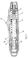
Figure 3 is the longitudinal section view through the device ofFigure 1 ; -
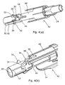
Figures 4(a) and 4(b) are detailed perspective view on a detail of the lancet release mechanism, with the blade element of the slider assembly removed for clarity; -
Figure 5 is a view of the slider assembly, lancet holder and trigger assembly for illustrating operating of the lancet holder lock; -
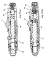
Figure 6 is a section view through the arrangement ofFigure 5 on an enlarged scale, prior to lock out of the lancet; -
Figure 7 is a view similar toFigure 6 but showing the lancet holder in a lock out condition; -
Figure 8 is a detailed section view for the front end of the device, with the slider in a forward position; -
Figure 9 is a perspective view of the slider assembly, with the thumb pad removed, -
Figure 10 is a view of the depth adjuster assembly when assembled; -
Figure 11 is an exploded view of the depth adjuster assembly; -
Figures 12(a), 12(b) and 12(c) are enlarged views for illustrating the cam track profile on the rear portion on the depth adjuster assembly; -
Figure 13 is a cross section view through the front and rear portions of the depth adjuster assembly; -
Figure 14 is a perspective, part cutaway view of a second embodiment of this invention in which the slider assembly is biased by integrally formed spring portions, and -
Figures 15(a) and (b) are side views through a third embodiment of lancing device in accordance with the invention, in an armed state and a fired state respectively. - Referring initially to
Figures 1 and 2 , the lancing device of this embodiment comprises amain housing 10 to the forward end of which is releasably attached adepth adjuster assembly 12. Projecting from the upper surface of themain housing 10 is an externallyaccessible thumb pad 14 of a slider assembly, the main part lying within the housing. Thethumb pad 14 is slideable in the reverse direction (away from the depth adjuster assembly) to prime or cock the device prior to use, and further movable forwardly, after use, to release a spent lancet from the front of the housing when the depth adjuster assembly has been removed. The device is fired by pressing afiring button 16 which rises proud of the housing when the device is cocked. - As seen in
Figure 2 , themain housing 10 is made up of arear body portion 18 and afront body portion 20 which snap together. Disposed within and acting against a rear inner surface of therear body portion 18 is amain drive spring 22, the forward end of which is received in a cylindrical recess in the rear part of alancet holder 24. Thelancet holder 24 is provided near its forward end with an integral resilient trigger latch finger 26 (visible on an in enlarged scale inFigures 3 and8 ). When thelancet holder 24 is shifted back from the position shown inFigure 3 by pressing rearwardly on thethumb pad 14, thetrigger latch finger 26 snaps past anabutment 28 on the inner surface of the housing to latch behind it and, as it does so, pushes out thetrigger button 16 so that it stands proud of the housing. At the front end of thelancet holder 24 is an integrally formed generallycylindrical socket 30 for receiving a lancet (not shown). As can be seen more clearly inFigures 4(a) and (b) an L-shaped slot extends down one side of the cylinder and circumferentially so as to provide staggered forward and rearward wall flaps that can be flexed or partially unwrapped to expand the effective internal diameter of thesocket 30. Also as seen inFigures 4(a) and (b) twocammed abutments abutments guide slot 38 in alongitudinal projection 40 of aslider assembly 42 of which thethumb pad 14 is an integral part. The walls of theprojection 40 defining thecontrol slot 38 are also longitudinally staggered, and each include achamfered gathering surface 44. - The
slider assembly 42 is constrained for linear sliding movement forward and rearward from the position shown inFigures 1 and3 against the influence of forward and arearward bias spring abutments control slot 38. Doing this 'unwraps' the wall portions of the socket partially to expand it to allow a lancet to be loaded or unloaded with minimal insertion or withdrawal force respectively. - The
socket 30 also has external projectingspring seats 50 which seat one end of acompression rebound spring 52, the other end of which is seated in an internal annular shoulder in thefront body portion 20. Surrounding the forward end of thelancet holder 24 and located in thefront body portion 20 against longitudinal movement is atrigger moulding 54 which resiliently carries thefiring button 16 through two live hinges 17. As seen more clearly inFigures 5 to 7 , the trigger moulding has two flexible lock outarms 56 on the outer surfaces of which are two ramp profiles 58. The lock outarms 56 are designed to cooperate with respective diametricallyopposed slider arms 60, having chamfered leadingedges 62. Theslider arms 60 are an integral part of theslider assembly 42. Thelancet holder 24 has a reduced width section behind thelancet receiving socket 30, defining two forward facing lock out shoulders 64. Sliding theslider assembly 42 forward from the position shown inFigure 6 causes theslider arms 60 to engage the ramp profiles 58 on the lock outarms 56 to urge them inwardly to the position shown inFigure 7 , where they block forward movement of thelancet holder 24. - The
slider assembly 42 includes in its base a prong orblade element 65 that projects forwardly one side of theprojection 40, and which extends beyond thetrigger moulding 54 to terminate just rearwardly of the front face of thefront body portion 20, when theslider assembly 42 is in its rest position. Theblade 65 is designed so that theslider assembly 42 cannot be moved forward from its rest position to release a lancet unless thedepth adjuster assembly 12 has been removed. - Referring more particularly to
Figures 10 to 13 , thedepth adjuster 12 is made up of a relatively fixedrear portion 66 that releasably connects to the front end of the front body portion by a snap fit or the like, in a single angular orientation, and which as noted blocks forward movement of theblade 65 when it is attached. Inside therear portion 66 are interrupted, forward facing cam surfaces 61, 63 respectively, that define a helical cam track that functions as a thread. Anaperture 68 in the rear portion allowsindicia 69 on the frontdepth adjuster portion 70 to be viewed. Internally, the wall section adjacent said aperture is locally thickened to provide clockwise andanti-clockwise stops front portion 70. The cam surfaces 61, 63 alternate and do not overlap in the axial sense and so this means that therear portion 62 can be moulded which can be opened and closed axially without requiring athreaded mould piece that has to be threaded out of the mould. Therear portion 62 also includes an innercylindrical sleeve 74 which generally surrounds thesocket 30 of the lancet holder. On the outer cylindrical wall of the sleeve is adetent pip 76 with twoslots 78 formed to allow resilient flexing of the detent pip. - The
depth adjuster portion 70 comprises a frustoconical form element terminating in atransverse wall 80 with alancet aperture 82 surrounded byequispaced projections 84, designed to provide a nerve distracting or confusion function. The remainder of the front depth adjuster part is internally splined 86 to cooperate with thedetent pip 76 on the rear portion to provide a click or detent action as the depth adjuster is rotated. On the rear edge of thefront portion 70 is formed acam follower part 88 which is chamfered as seen inFigures 11 and13 , to allow it to snap past one or more of the cam surfaces 61, 63 on therear portion 64. This means that the front andrear portions depth adjuster assembly 12 can be assembled simply by pushing one axially into the other, and no rotation is required. The snap action is designed to be sufficiently robust that the two parts cannot readily be separated once assembled. Once assembled, the front depth adjuster part can be rotated through approximately 270° with the rotation progressively adjusting the relative axial position thereby to vary the effective penetration depth of the lancing operation. - In operation of the device, having set the
depth adjuster assembly 12 to give the required penetration, the depth adjuster assembly is removed from the front end of the device and theslider assembly 42 moved forward by thumb pressure on thethumb pad 14 to release a spent lancet (if present) by expanding thesocket 30 of the lancet holder due to the action of theabutments slot 38 of theprojections 40. Whilst held in the expanded position, a fresh lancet may be located in the lancet holder without requiring any significant axial force. Having inserted the lancet, the slider is allowed to return to its rest position and returning the socket to its non-expanded form, thereby gripping the lancet. Thedepth adjuster assembly 12 is then reapplied to the front of the device and the device cocked by sliding the slider rearwardly. The slider assembly engages the lancet holder and pushes it back against the force of thedrive spring 22 until theresilient finger 26 snaps rearwardly past theabutment 28 on the housing to latch and in so doing, pushes thetrigger button 16 proud. The user will then offer the device up to the penetration site and fire the lancet by pressingbutton 16. - In a modification, not shown, the
thumb pad 14 may be extended forwardly so that, in its rest position, its forward edge lies just to the rear of the aperture in which thetrigger button 16 sits. By doing this, when the device is cocked and thetrigger button 16 pushed proud of the housing by latching of the lancet holder, the lancet button blocks forward movement of thethumb pad 14 and so it is not possible to move the slider forward until after the device has been fired. - In a second embodiment, shown in
Figure 14 , the forward and rearward bias springs 46 and 48 that bias the slider assembly may be replaced by integrally mouldedspring portions - Referring now to the third embodiment, this is similar in construction to the previous embodiments and like components are given the same reference numerals and will not be described in detail again. In the first and second embodiments, when the device is fired, forward travel of the
lancet holder 24 is limited by a forward facing abutment surface on the lancet holder moving into abutment with a rearward facing abutment surface on the housing or a component associated therewith. In the third embodiment, forward travel of thelancet holder 24 is limited by a forward facingabutment surface 90 on aformation 92 at the rear end of thelancet holder 24 engaging a rearward facingshoulder 94 protruding inwardly from the housing wall. - Embodiments of the invention may further comprise one or more features in accordance with the following numbered statements:
- 1. A lancing device comprising:
- a housing (10, 12);
- a lancet holder (24) movably mounted for movement in a lancing direction within said housing, the lancet holder having a forward portion defining a socket (30) for partially surrounding and retaining in use a rear portion of a lancet, the socket being expandable to allow insertion and/or removal of said lancet, and
- a lancet release element (40, 42) movable in a direction generally parallel to a said lancing movement direction between a rest and a release position to cause said socket to move between a lancet retaining condition and an expanded condition.
- 2. A lancing device according to statement 1, wherein said socket is defined by a generally cylindrical wall of resilient material having a slot (32) therein to allow resilient expansion and/or contraction.
- 3. A lancing device according to statement 2, wherein said cylindrical wall is provided with radially outwardly extending abutments (34, 36) spaced one to either side of said slot (32), said release element (40, 42) having respective cam surfaces (44) cooperating with said abutment, whereby movement of the release element (40, 42) causes movement of the socket between its expanded condition and its lancet retaining condition.
- 4. A lancing device according to any preceding statement, wherein said lancet release element (40, 42) is movable forwardly from a rest position to expand said socket.
- 5. A lancing device according to statement 4, wherein said lancet release element (40, 42) is additionally movable rearwardly to cock said lancet.
- 6. A lancing device according to any of the preceding statements, wherein movement of said lancet release element towards said release position causes holding or limiting forward movement of said lancet holder (24).
- 7. A lancing device having:
- a housing (10, 12);
- a lancet holder (24) movably mounted within said housing, the lancet holder having a forward portion for receiving in use a lancet, and
- a lancet release element (40, 42) for being moved to allow release of a lancet from said lancet holder,
- wherein, movement of said lancet release element (40, 42) to release the lancet causes blocking or limiting of forward movement of said lancet holder.
- 8. A lancing device according to statement 7, wherein said housing (10, 12), or a component associated therewith, includes a lancet holder restraining element (56) movable between a position in which it blocks forward movement of said lancet holder (24), and a free position in which forward movement of the lancet holder (24) is not blocked thereby.
- 9. A lancing device according to statement 8, wherein said lancet release element (40, 42) has a control surface (62) which, as said lancet release element is moved to release the lancet engages said locking element (56) to move to its blocking position.
- 10. A lancing device according to any of the statements 7 to 9, including a trigger arrangement (54) operable to latch and release said lancet holder (24) for movement under the influence of a drive spring, wherein said lancet holder restricting element (56) is part of said trigger arrangement (54).
- 11. A lancing device having:
- a housing comprising a main body portion (10) and a forward nose portion (12) removable and replaceable to allow loading and unloading of a lancet in use;
- a lancet holder (24) movably mounted in said housing and having a forward portion for receiving a lancet in use;
- a lancet release element (40, 42) movable between a rest position and a release position, wherein movement of said lancet release element (40, 42) to its release position is prevented or resisted by said forward nose portion (12) when connected to said main body portion.
- 12. A lancing device according to statement 11, wherein said lancet release element (40, 42) is movable longitudinally and includes an elongate extension (60) adapted to cooperate with said forward nose portion (12) to prevent movement.
- 13. A skin penetration device including:
- a housing (10, 12);
- a movable insertion element disposed in said housing and having a sharp tip and adapted to be inserted into the skin of a recipient;
- a depth penetration arrangement comprising a first, relatively fixed portion (66) forming part of or secured to said housing, and
- a skin contacting portion (20) being mounted for angular movement about an axis on said relatively fixed portion;
- one of the relatively fixed portion (66, 70) and the skin contacting portions having an interrupted cam surface (61, 63), and the other having a cam follower (88) adapted to cooperate with said cam surface whereby relative rotation of said skin contacting portion and said fixed portion varies the relative axial position thereof.
- 14. A skin penetration device according to statement 13, wherein said relatively fixed portion and said skin contacting portion include respective detent elements (86) to prevent a detent action at spaced angular positions.
- 15. A skin penetration device according to statement 13 or
statement 14, wherein a stop surface (71, 72) is associated with said cam surface to limit relative rotation of said relatively movable member. - 16. A skin penetration device according to any of statements 13 to 15, wherein said interrupted cam surface (61, 63) follows a generally helical path with respect to the axis, the cam surface including alternate opposite facing cam face elements (61, 63) together defining a cam track for said cam follower.
- 17. A skin penetration device according to
statement 16, wherein the cam surface elements are of lesser circumferential extent than said cam follower (88). - 18. A skin penetration device according to any of statements 13 to 17, wherein at least one of the cam surface (61, 63) and said cam follower (88) are resiliently deformable to allow said cam follower (88) to be introduced into said cam track by the application of an axial load.
- 19. A skin penetration device according to any of statements 13 to 18, wherein said cam follower (88) is provided on said skin contacting portion (70) and said cam track (61, 63) is provided on said relatively fixed portion (66).
- 20. A lancing device having:
- a housing (10, 12);
- a lancet holder (24) removably mounted within said housing, the lancet holder having a forward portion for receiving in use a lancet;
- a lancet release element (40, 42) for being removed to allow release of a lancet from said lancet holder;
- a trigger arrangement operable to latch and release said lancet holder (24) for movement under the influence of a drive spring (22), said trigger arrangement including a trigger element (16) which, when said lancet holder (24) is latched, is in an armed position ready to fire, and
- wherein when the lancet holder (24) is latched, with the trigger arrangement in its armed position, the trigger arrangement blocks effective movement of said lancet release element (24) to release a lancet.
- 21. A lancing device according to
statement 20, wherein said trigger element (16) projects from the surface of said housing when in the armed condition and the lancet release element (40, 42) comprises an externally accessible manually operable control element (14), and the trigger element in its armed position lies in the projected path of the control element.
Claims (9)
- A skin penetration device including:a housing (10, 12);a movable insertion element disposed in said housing and having a sharp tip and adapted to be inserted into the skin of a recipient;a depth penetration arrangement comprising a first, relatively fixed portion (66) forming part of or secured to said housing, anda skin contacting portion (20) being mounted for angular movement about an axis on said relatively fixed portion;one of the relatively fixed portion (66, 70) and the skin contacting portions having an interrupted cam surface (61, 63), and the other having a cam follower (88) adapted to cooperate with said cam surface whereby relative rotation of said skin contacting portion and said fixed portion varies the relative axial position thereof.
- A skin penetration device according to Claim 1, wherein said relatively fixed portion and said skin contacting portion include respective detent elements (86) to provide a detent action at spaced angular positions.
- A skin penetration device according to Claim 1 or Claim 2, wherein a stop surface (71, 72) is associated with said cam surface to limit relative rotation of said relatively movable member.
- A skin penetration device according to any of Claims 1 to 3, wherein said interrupted cam surface (61, 63) follows a generally helical path with respect to the axis, the cam surface including alternate opposite facing cam face elements (61, 63) together defining a cam track for said cam follower.
- A skin penetration device according to Claim 4, wherein the cam surface elements are of lesser circumferential extent than said cam follower (88).
- A skin penetration device according to any of Claims 1 to 5, wherein at least one of the cam surface (61, 63) and said cam follower (88) are resiliently deformable to allow said cam follower (88) to be introduced into said cam track by the application of an axial load.
- A skin penetration device according to any of Claims 1 to 6, wherein said cam follower (88) is provided on said skin contacting portion (70) and said cam track (61, 63) is provided on said relatively fixed portion (66).
- A lancing device having:a housing comprising a main body portion (10) and a forward nose portion (12) removable and replaceable to allow loading and unloading of a lancet in use;a lancet holder (24) movably mounted in said housing and having a forward portion for receiving a lancet in use;a lancet release element (40, 42) movable between a rest position and a release position, wherein movement of said lancet release element (40, 42) to its release position is prevented or resisted by said forward nose portion (12) when connected to said main body portion.
- A lancing device having:a housing (10, 12);a lancet holder (24) removably mounted within said housing, the lancet holder having a forward portion for receiving in use a lancet;a lancet release element (40, 42) for being removed to allow release of a lancet from said lancet holder;a trigger arrangement operable to latch and release said lancet holder (24) for movement under the influence of a drive spring (22), said trigger arrangement including a trigger element (16) which, when said lancet holder (24) is latched, is in an armed position ready to fire, andwherein when the lancet holder (24) is latched, with the trigger arrangement in its armed position, the trigger arrangement blocks effective movement of said lancet release element (24) to release a lancet.
Priority Applications (2)
| Application Number | Priority Date | Filing Date | Title |
|---|---|---|---|
| PL15154913T PL2907449T3 (en) | 2011-04-08 | 2012-04-04 | Skin penetration device |
| EP16176969.0A EP3100679A1 (en) | 2011-04-08 | 2012-04-04 | Skin penetration device |
Applications Claiming Priority (3)
| Application Number | Priority Date | Filing Date | Title |
|---|---|---|---|
| US201161473251P | 2011-04-08 | 2011-04-08 | |
| GB1105950.8A GB2489740A (en) | 2011-04-08 | 2011-04-08 | Means for securely retaining a lancet in a lancing device |
| EP12720263.8A EP2677933B1 (en) | 2011-04-08 | 2012-04-04 | Skin penetration device |
Related Parent Applications (2)
| Application Number | Title | Priority Date | Filing Date |
|---|---|---|---|
| EP12720263.8A Division EP2677933B1 (en) | 2011-04-08 | 2012-04-04 | Skin penetration device |
| EP12720263.8A Division-Into EP2677933B1 (en) | 2011-04-08 | 2012-04-04 | Skin penetration device |
Related Child Applications (2)
| Application Number | Title | Priority Date | Filing Date |
|---|---|---|---|
| EP16176969.0A Division EP3100679A1 (en) | 2011-04-08 | 2012-04-04 | Skin penetration device |
| EP16176969.0A Division-Into EP3100679A1 (en) | 2011-04-08 | 2012-04-04 | Skin penetration device |
Publications (3)
| Publication Number | Publication Date |
|---|---|
| EP2907449A2 true EP2907449A2 (en) | 2015-08-19 |
| EP2907449A3 EP2907449A3 (en) | 2015-11-18 |
| EP2907449B1 EP2907449B1 (en) | 2016-11-30 |
Family
ID=44072147
Family Applications (5)
| Application Number | Title | Priority Date | Filing Date |
|---|---|---|---|
| EP12720263.8A Active EP2677933B1 (en) | 2011-04-08 | 2012-04-04 | Skin penetration device |
| EP15154913.6A Active EP2907449B1 (en) | 2011-04-08 | 2012-04-04 | Skin penetration device |
| EP15159027.0A Active EP2910188B1 (en) | 2011-04-08 | 2012-04-04 | Skin penetration device |
| EP13185802.9A Active EP2682056B1 (en) | 2011-04-08 | 2012-04-04 | Skin penetration device |
| EP16176969.0A Withdrawn EP3100679A1 (en) | 2011-04-08 | 2012-04-04 | Skin penetration device |
Family Applications Before (1)
| Application Number | Title | Priority Date | Filing Date |
|---|---|---|---|
| EP12720263.8A Active EP2677933B1 (en) | 2011-04-08 | 2012-04-04 | Skin penetration device |
Family Applications After (3)
| Application Number | Title | Priority Date | Filing Date |
|---|---|---|---|
| EP15159027.0A Active EP2910188B1 (en) | 2011-04-08 | 2012-04-04 | Skin penetration device |
| EP13185802.9A Active EP2682056B1 (en) | 2011-04-08 | 2012-04-04 | Skin penetration device |
| EP16176969.0A Withdrawn EP3100679A1 (en) | 2011-04-08 | 2012-04-04 | Skin penetration device |
Country Status (10)
| Country | Link |
|---|---|
| US (1) | US9603563B2 (en) |
| EP (5) | EP2677933B1 (en) |
| JP (2) | JP6148224B2 (en) |
| CN (2) | CN103458787B (en) |
| BR (1) | BR112013025795A2 (en) |
| GB (1) | GB2489740A (en) |
| IN (1) | IN2014DN01836A (en) |
| MX (1) | MX338788B (en) |
| PL (4) | PL2910188T3 (en) |
| WO (1) | WO2012137001A1 (en) |
Families Citing this family (8)
| Publication number | Priority date | Publication date | Assignee | Title |
|---|---|---|---|---|
| US20140214065A1 (en) * | 2013-01-29 | 2014-07-31 | Yong Pil Kim | Blood lancet device |
| TW201513832A (en) * | 2013-10-11 | 2015-04-16 | Ysp Co Ltd | Blood collecting apparatus, lancet and lancing device |
| USD758566S1 (en) * | 2014-03-17 | 2016-06-07 | Erik Chen | Blood sampling pen |
| USD774641S1 (en) * | 2015-11-11 | 2016-12-20 | Merck Sharp & Dohme Corp. | Auto injector |
| US20180015224A1 (en) | 2016-07-13 | 2018-01-18 | California Institute Of Technology | Dampers and Methods for Performing Measurements in an Autoinjector |
| KR102090541B1 (en) * | 2017-09-29 | 2020-05-27 | 최임철 | Pressure-Activated Disposable Pain-Free Lancet |
| CN108982604A (en) * | 2018-08-04 | 2018-12-11 | 北京怡成生物电子技术股份有限公司 | The portable monitoring system of analyte in a kind of dynamic METHOD FOR CONTINUOUS DETERMINATION body fluid |
| CN115475324A (en) * | 2021-06-16 | 2022-12-16 | 苏州悦肤达医疗科技有限公司 | Needle assisting device and medical device |
Family Cites Families (70)
| Publication number | Priority date | Publication date | Assignee | Title |
|---|---|---|---|---|
| US4976724A (en) | 1989-08-25 | 1990-12-11 | Lifescan, Inc. | Lancet ejector mechanism |
| ATE179876T1 (en) | 1991-11-12 | 1999-05-15 | Urs A Ramel | LANCET DEVICE |
| US5282822A (en) | 1993-01-19 | 1994-02-01 | Sherwood Medical Company | Lancet ejector for lancet injector |
| US5464418A (en) | 1993-12-09 | 1995-11-07 | Schraga; Steven | Reusable lancet device |
| AUPN689695A0 (en) | 1995-12-01 | 1995-12-21 | Brakey, Dale Robert | Blood letting device |
| US5613978A (en) | 1996-06-04 | 1997-03-25 | Palco Laboratories | Adjustable tip for lancet device |
| GB9616953D0 (en) * | 1996-08-13 | 1996-09-25 | Owen Mumford Ltd | Improvements relating to skin prickers |
| US5916230A (en) * | 1997-06-16 | 1999-06-29 | Bayer Corporation | Blood sampling device with adjustable end cap |
| US6949111B2 (en) | 1998-02-13 | 2005-09-27 | Steven Schraga | Lancet device |
| US6022366A (en) | 1998-06-11 | 2000-02-08 | Stat Medical Devices Inc. | Lancet having adjustable penetration depth |
| US6346114B1 (en) | 1998-06-11 | 2002-02-12 | Stat Medical Devices, Inc. | Adjustable length member such as a cap of a lancet device for adjusting penetration depth |
| US6197040B1 (en) * | 1999-02-23 | 2001-03-06 | Lifescan, Inc. | Lancing device having a releasable connector |
| US6558402B1 (en) * | 1999-08-03 | 2003-05-06 | Becton, Dickinson And Company | Lancer |
| US6283982B1 (en) * | 1999-10-19 | 2001-09-04 | Facet Technologies, Inc. | Lancing device and method of sample collection |
| US6322575B1 (en) | 2000-01-05 | 2001-11-27 | Steven Schraga | Lancet depth adjustment assembly |
| DE10053974A1 (en) | 2000-10-31 | 2002-05-29 | Roche Diagnostics Gmbh | Blood collection system |
| CN1313052C (en) | 2001-01-12 | 2007-05-02 | 爱科来株式会社 | Puncturing device |
| GB0103977D0 (en) | 2001-02-17 | 2001-04-04 | Owen Mumford Ltd | Improvements relating to skin prickers |
| EP1408852A4 (en) | 2001-06-13 | 2009-09-09 | Steven Schraga | Single use lancet device |
| EP1405595B2 (en) | 2001-07-11 | 2010-09-01 | ARKRAY, Inc. | Piercing device |
| DE20114658U1 (en) | 2001-09-05 | 2001-11-15 | Wilden Engineering Und Vertrie | Lancet for taking blood |
| US6645219B2 (en) | 2001-09-07 | 2003-11-11 | Amira Medical | Rotatable penetration depth adjusting arrangement |
| US20030100913A1 (en) | 2001-10-09 | 2003-05-29 | Guoping Shi | Depth adjustable cap of lancing device |
| US20040098010A1 (en) * | 2001-10-22 | 2004-05-20 | Glenn Davison | Confuser crown skin pricker |
| JP4257943B2 (en) | 2002-07-29 | 2009-04-30 | アークレイ株式会社 | Puncture unit and puncture member removal tool |
| US6852119B1 (en) | 2002-09-09 | 2005-02-08 | Ramzi F. Abulhaj | Adjustable disposable lancet and method |
| WO2004091402A1 (en) | 2003-04-16 | 2004-10-28 | Arkray Inc. | Puncture device |
| JP4761701B2 (en) * | 2003-05-21 | 2011-08-31 | アークレイ株式会社 | Puncture device with adjustable puncture depth |
| US7905898B2 (en) | 2003-08-15 | 2011-03-15 | Stat Medical Devices, Inc. | Adjustable lancet device and method |
| WO2005034753A1 (en) | 2003-10-15 | 2005-04-21 | Surgilance Pte Ltd | Lancet assembly |
| EP1708610A1 (en) | 2004-01-12 | 2006-10-11 | Minnesota Scientific, Inc. | Apparatus for retaining otherwise hand-held retractors |
| US20050159768A1 (en) | 2004-01-15 | 2005-07-21 | Home Diagnostics, Inc. | Lancing device |
| CN101309642A (en) | 2004-03-15 | 2008-11-19 | 香港澳维有限公司 | Lancet device and method of use |
| US7670352B1 (en) | 2004-03-24 | 2010-03-02 | Caribbean Medical Brokers, Inc. | Adjustable tip with integrated detent for blood lancet system |
| US7955347B2 (en) | 2004-06-25 | 2011-06-07 | Facet Technologies, Llc | Low cost safety lancet |
| GB2421439B (en) | 2004-12-21 | 2009-07-29 | Owen Mumford Ltd | Skin pricking apparatus |
| DE602006015462D1 (en) * | 2005-03-04 | 2010-08-26 | Bayer Healthcare Llc | LANCE TES RELEASE MECHANISM |
| WO2006107914A2 (en) * | 2005-04-04 | 2006-10-12 | Facet Technologies, Llc | Narrow-profile lancing device |
| US20060247670A1 (en) * | 2005-05-02 | 2006-11-02 | Levaughn Richard W | Lancing device with automatic lancet release |
| US20070083222A1 (en) | 2005-06-16 | 2007-04-12 | Stat Medical Devices, Inc. | Lancet device, removal system for lancet device, and method |
| CN101856231A (en) | 2006-03-08 | 2010-10-13 | 爱科来株式会社 | Lancet device |
| CN101400302B (en) * | 2006-03-10 | 2010-11-03 | 爱科来株式会社 | Lancet device |
| WO2007130830A2 (en) | 2006-04-25 | 2007-11-15 | Facet Technologies, Llc | Lancing device with independent drive core |
| JP5028414B2 (en) | 2006-05-10 | 2012-09-19 | パナソニック株式会社 | Puncture device and puncture needle cartridge |
| US7955348B2 (en) | 2006-06-15 | 2011-06-07 | Abbott Diabetes Care Inc. | Lancing devices and methods |
| JP4997247B2 (en) | 2006-09-29 | 2012-08-08 | テルモ株式会社 | Disposable cartridge |
| US8043318B2 (en) | 2007-02-08 | 2011-10-25 | Stat Medical Devices, Inc. | Push-button lance device and method |
| WO2008111936A1 (en) | 2007-03-12 | 2008-09-18 | Bayer Healthcare Llc | Lancet-eject mechanism |
| KR100820523B1 (en) | 2007-03-14 | 2008-04-08 | 홍관호 | Blood lancet device |
| US8469986B2 (en) | 2007-03-30 | 2013-06-25 | Stat Medical Devices, Inc. | Lancet device with combined trigger and cocking mechanism and method |
| US9179867B2 (en) | 2007-06-19 | 2015-11-10 | Stat Medical Devices, Inc. | Lancet device with depth adjustment and lancet removal system and method |
| GB2451840B (en) * | 2007-08-14 | 2012-01-18 | Owen Mumford Ltd | Lancing devices |
| GB0715803D0 (en) * | 2007-08-14 | 2007-09-26 | Owen Mumford Ltd | Lancing devices |
| GB0715798D0 (en) * | 2007-08-14 | 2007-09-19 | Owen Mumford Ltd | Lancing devices |
| WO2009035084A1 (en) | 2007-09-12 | 2009-03-19 | Izumi-Cosmo Company, Limited | Lancet assembly |
| ATE505134T1 (en) | 2007-10-19 | 2011-04-15 | Bionime Corp | LIVING DEVICE |
| EP2221000B1 (en) | 2007-11-27 | 2012-09-19 | ARKRAY, Inc. | Puncture device |
| CN201104887Y (en) * | 2007-12-05 | 2008-08-27 | 成都瑞琦科技实业有限责任公司 | Novel vena blood taking needle |
| US8454533B2 (en) | 2008-05-09 | 2013-06-04 | Lifescan Scotland Limited | Lancing devices and methods |
| US8932314B2 (en) | 2008-05-09 | 2015-01-13 | Lifescan Scotland Limited | Prime and fire lancing device with contacting bias drive and method |
| US20090281457A1 (en) * | 2008-05-09 | 2009-11-12 | Lifescan Soctland Ltd. | Prime and fire lancing device with non-contacting bias drive and method |
| WO2009148431A1 (en) | 2008-06-05 | 2009-12-10 | Bayer Healthcare Llc | Lancing device |
| US8123772B2 (en) | 2008-08-14 | 2012-02-28 | Abbott Diabetes Care Inc. | Cap for lancing device with adjustable mode of operation |
| US20100049233A1 (en) | 2008-08-25 | 2010-02-25 | Abbott Diabetes Care Inc. | Lancet having integrated drive mechanism |
| EP2174591B1 (en) | 2008-10-09 | 2019-01-16 | Roche Diabetes Care GmbH | Puncture instrument |
| US8568434B2 (en) | 2008-10-14 | 2013-10-29 | Bionime Corporation | Lancing device |
| WO2010064998A1 (en) | 2008-12-04 | 2010-06-10 | Venture Corporation Limited | A lancing device |
| WO2010080585A1 (en) | 2008-12-18 | 2010-07-15 | Facet Technologies, Llc | Lancing device and lancet |
| CN101444428B (en) | 2008-12-30 | 2010-04-07 | 苏州施莱医疗器械有限公司 | Safe portable disposable automatic blood-taking needle |
| US8317812B2 (en) * | 2009-07-29 | 2012-11-27 | Wah Leong Lum | Lancet device with lance retraction |
-
2011
- 2011-04-08 GB GB1105950.8A patent/GB2489740A/en not_active Withdrawn
-
2012
- 2012-04-04 JP JP2014503214A patent/JP6148224B2/en active Active
- 2012-04-04 PL PL15159027.0T patent/PL2910188T3/en unknown
- 2012-04-04 CN CN201280015833.4A patent/CN103458787B/en active Active
- 2012-04-04 EP EP12720263.8A patent/EP2677933B1/en active Active
- 2012-04-04 EP EP15154913.6A patent/EP2907449B1/en active Active
- 2012-04-04 PL PL13185802T patent/PL2682056T3/en unknown
- 2012-04-04 MX MX2013011649A patent/MX338788B/en active IP Right Grant
- 2012-04-04 WO PCT/GB2012/050761 patent/WO2012137001A1/en active Application Filing
- 2012-04-04 PL PL12720263T patent/PL2677933T3/en unknown
- 2012-04-04 BR BR112013025795A patent/BR112013025795A2/en not_active IP Right Cessation
- 2012-04-04 CN CN201510557882.6A patent/CN105105765B/en active Active
- 2012-04-04 IN IN1836DEN2014 patent/IN2014DN01836A/en unknown
- 2012-04-04 EP EP15159027.0A patent/EP2910188B1/en active Active
- 2012-04-04 US US14/110,526 patent/US9603563B2/en active Active
- 2012-04-04 PL PL15154913T patent/PL2907449T3/en unknown
- 2012-04-04 EP EP13185802.9A patent/EP2682056B1/en active Active
- 2012-04-04 EP EP16176969.0A patent/EP3100679A1/en not_active Withdrawn
-
2017
- 2017-02-16 JP JP2017026684A patent/JP2017113588A/en active Pending
Also Published As
| Publication number | Publication date |
|---|---|
| EP2907449A3 (en) | 2015-11-18 |
| PL2682056T3 (en) | 2015-08-31 |
| GB2489740A (en) | 2012-10-10 |
| PL2910188T3 (en) | 2016-11-30 |
| EP3100679A1 (en) | 2016-12-07 |
| EP2910188B1 (en) | 2016-06-01 |
| GB201105950D0 (en) | 2011-05-18 |
| CN103458787A (en) | 2013-12-18 |
| EP2677933A1 (en) | 2014-01-01 |
| CN103458787B (en) | 2015-09-09 |
| US9603563B2 (en) | 2017-03-28 |
| JP6148224B2 (en) | 2017-06-14 |
| US20140121691A1 (en) | 2014-05-01 |
| EP2910188A1 (en) | 2015-08-26 |
| PL2907449T3 (en) | 2017-05-31 |
| EP2682056B1 (en) | 2015-01-14 |
| IN2014DN01836A (en) | 2015-05-15 |
| CN105105765B (en) | 2018-04-24 |
| JP2017113588A (en) | 2017-06-29 |
| EP2682056A1 (en) | 2014-01-08 |
| PL2677933T3 (en) | 2015-11-30 |
| JP2014512908A (en) | 2014-05-29 |
| MX2013011649A (en) | 2013-11-01 |
| EP2907449B1 (en) | 2016-11-30 |
| MX338788B (en) | 2016-05-02 |
| EP2677933B1 (en) | 2015-06-10 |
| WO2012137001A1 (en) | 2012-10-11 |
| BR112013025795A2 (en) | 2016-12-27 |
| CN105105765A (en) | 2015-12-02 |
Similar Documents
| Publication | Publication Date | Title |
|---|---|---|
| EP2907449B1 (en) | Skin penetration device | |
| EP3030287B1 (en) | Power unit | |
| EP2185073B1 (en) | Lancing devices | |
| JP4847316B2 (en) | Needle protection device for syringe and injection device provided with syringe and needle protection device | |
| JP5074397B2 (en) | Grip ring for use with needle cover assembly and needle tip assembly | |
| CN108136119B (en) | Injection device with syringe carrier locking element | |
| EP2486852B1 (en) | Lancing device | |
| JP2009506816A5 (en) | ||
| JP2014503287A (en) | Automatic injection device having a contact surface that provides resistance to movement of the trigger component towards the firing position | |
| GB2486690A (en) | An autoinjector cap which also removes the needle shield | |
| EP3154611B1 (en) | Plunger segments drive mechanism for a medicament delivery device | |
| EP3323448A1 (en) | Medicament delivery device | |
| WO2011084103A1 (en) | A lancet | |
| EP3380156B1 (en) | Medicament delivery device | |
| EP4299090A1 (en) | Autoinjector with resilient adjustment means between plunger rod and barrel | |
| US20130317533A1 (en) | Lancet device | |
| WO2023198566A1 (en) | Autoinjector for automatic injection of a product into an injection site |
Legal Events
| Date | Code | Title | Description |
|---|---|---|---|
| PUAI | Public reference made under article 153(3) epc to a published international application that has entered the european phase |
Free format text: ORIGINAL CODE: 0009012 |
|
| AC | Divisional application: reference to earlier application |
Ref document number: 2677933 Country of ref document: EP Kind code of ref document: P |
|
| AK | Designated contracting states |
Kind code of ref document: A2 Designated state(s): AL AT BE BG CH CY CZ DE DK EE ES FI FR GB GR HR HU IE IS IT LI LT LU LV MC MK MT NL NO PL PT RO RS SE SI SK SM TR |
|
| PUAL | Search report despatched |
Free format text: ORIGINAL CODE: 0009013 |
|
| AK | Designated contracting states |
Kind code of ref document: A3 Designated state(s): AL AT BE BG CH CY CZ DE DK EE ES FI FR GB GR HR HU IE IS IT LI LT LU LV MC MK MT NL NO PL PT RO RS SE SI SK SM TR |
|
| RIC1 | Information provided on ipc code assigned before grant |
Ipc: A61B 5/151 20060101ALI20151014BHEP Ipc: A61B 5/15 20060101AFI20151014BHEP |
|
| 17P | Request for examination filed |
Effective date: 20151125 |
|
| RBV | Designated contracting states (corrected) |
Designated state(s): AL AT BE BG CH CY CZ DE DK EE ES FI FR GB GR HR HU IE IS IT LI LT LU LV MC MK MT NL NO PL PT RO RS SE SI SK SM TR |
|
| GRAP | Despatch of communication of intention to grant a patent |
Free format text: ORIGINAL CODE: EPIDOSNIGR1 |
|
| RIC1 | Information provided on ipc code assigned before grant |
Ipc: A61B 5/15 20060101AFI20160208BHEP Ipc: A61B 5/151 20060101ALI20160208BHEP |
|
| INTG | Intention to grant announced |
Effective date: 20160308 |
|
| GRAJ | Information related to disapproval of communication of intention to grant by the applicant or resumption of examination proceedings by the epo deleted |
Free format text: ORIGINAL CODE: EPIDOSDIGR1 |
|
| GRAS | Grant fee paid |
Free format text: ORIGINAL CODE: EPIDOSNIGR3 |
|
| GRAP | Despatch of communication of intention to grant a patent |
Free format text: ORIGINAL CODE: EPIDOSNIGR1 |
|
| INTC | Intention to grant announced (deleted) | ||
| INTG | Intention to grant announced |
Effective date: 20160801 |
|
| GRAJ | Information related to disapproval of communication of intention to grant by the applicant or resumption of examination proceedings by the epo deleted |
Free format text: ORIGINAL CODE: EPIDOSDIGR1 |
|
| GRAL | Information related to payment of fee for publishing/printing deleted |
Free format text: ORIGINAL CODE: EPIDOSDIGR3 |
|
| INTC | Intention to grant announced (deleted) | ||
| GRAA | (expected) grant |
Free format text: ORIGINAL CODE: 0009210 |
|
| AC | Divisional application: reference to earlier application |
Ref document number: 2677933 Country of ref document: EP Kind code of ref document: P |
|
| AK | Designated contracting states |
Kind code of ref document: B1 Designated state(s): AL AT BE BG CH CY CZ DE DK EE ES FI FR GB GR HR HU IE IS IT LI LT LU LV MC MK MT NL NO PL PT RO RS SE SI SK SM TR |
|
| REG | Reference to a national code |
Ref country code: CH Ref legal event code: EP Ref country code: GB Ref legal event code: FG4D |
|
| REG | Reference to a national code |
Ref country code: AT Ref legal event code: REF Ref document number: 849040 Country of ref document: AT Kind code of ref document: T Effective date: 20161215 |
|
| REG | Reference to a national code |
Ref country code: IE Ref legal event code: FG4D |
|
| REG | Reference to a national code |
Ref country code: DE Ref legal event code: R096 Ref document number: 602012026211 Country of ref document: DE |
|
| REG | Reference to a national code |
Ref country code: CH Ref legal event code: NV Representative=s name: CRONIN INTELLECTUAL PROPERTY, CH |
|
| PG25 | Lapsed in a contracting state [announced via postgrant information from national office to epo] |
Ref country code: LV Free format text: LAPSE BECAUSE OF FAILURE TO SUBMIT A TRANSLATION OF THE DESCRIPTION OR TO PAY THE FEE WITHIN THE PRESCRIBED TIME-LIMIT Effective date: 20161130 |
|
| REG | Reference to a national code |
Ref country code: LT Ref legal event code: MG4D |
|
| REG | Reference to a national code |
Ref country code: NL Ref legal event code: MP Effective date: 20161130 |
|
| REG | Reference to a national code |
Ref country code: AT Ref legal event code: MK05 Ref document number: 849040 Country of ref document: AT Kind code of ref document: T Effective date: 20161130 |
|
| REG | Reference to a national code |
Ref country code: FR Ref legal event code: PLFP Year of fee payment: 6 |
|
| PG25 | Lapsed in a contracting state [announced via postgrant information from national office to epo] |
Ref country code: GR Free format text: LAPSE BECAUSE OF FAILURE TO SUBMIT A TRANSLATION OF THE DESCRIPTION OR TO PAY THE FEE WITHIN THE PRESCRIBED TIME-LIMIT Effective date: 20170301 Ref country code: SE Free format text: LAPSE BECAUSE OF FAILURE TO SUBMIT A TRANSLATION OF THE DESCRIPTION OR TO PAY THE FEE WITHIN THE PRESCRIBED TIME-LIMIT Effective date: 20161130 Ref country code: LT Free format text: LAPSE BECAUSE OF FAILURE TO SUBMIT A TRANSLATION OF THE DESCRIPTION OR TO PAY THE FEE WITHIN THE PRESCRIBED TIME-LIMIT Effective date: 20161130 Ref country code: NO Free format text: LAPSE BECAUSE OF FAILURE TO SUBMIT A TRANSLATION OF THE DESCRIPTION OR TO PAY THE FEE WITHIN THE PRESCRIBED TIME-LIMIT Effective date: 20170228 |
|
| PG25 | Lapsed in a contracting state [announced via postgrant information from national office to epo] |
Ref country code: FI Free format text: LAPSE BECAUSE OF FAILURE TO SUBMIT A TRANSLATION OF THE DESCRIPTION OR TO PAY THE FEE WITHIN THE PRESCRIBED TIME-LIMIT Effective date: 20161130 Ref country code: HR Free format text: LAPSE BECAUSE OF FAILURE TO SUBMIT A TRANSLATION OF THE DESCRIPTION OR TO PAY THE FEE WITHIN THE PRESCRIBED TIME-LIMIT Effective date: 20161130 Ref country code: AT Free format text: LAPSE BECAUSE OF FAILURE TO SUBMIT A TRANSLATION OF THE DESCRIPTION OR TO PAY THE FEE WITHIN THE PRESCRIBED TIME-LIMIT Effective date: 20161130 Ref country code: RS Free format text: LAPSE BECAUSE OF FAILURE TO SUBMIT A TRANSLATION OF THE DESCRIPTION OR TO PAY THE FEE WITHIN THE PRESCRIBED TIME-LIMIT Effective date: 20161130 Ref country code: PT Free format text: LAPSE BECAUSE OF FAILURE TO SUBMIT A TRANSLATION OF THE DESCRIPTION OR TO PAY THE FEE WITHIN THE PRESCRIBED TIME-LIMIT Effective date: 20170330 Ref country code: ES Free format text: LAPSE BECAUSE OF FAILURE TO SUBMIT A TRANSLATION OF THE DESCRIPTION OR TO PAY THE FEE WITHIN THE PRESCRIBED TIME-LIMIT Effective date: 20161130 |
|
| PG25 | Lapsed in a contracting state [announced via postgrant information from national office to epo] |
Ref country code: NL Free format text: LAPSE BECAUSE OF FAILURE TO SUBMIT A TRANSLATION OF THE DESCRIPTION OR TO PAY THE FEE WITHIN THE PRESCRIBED TIME-LIMIT Effective date: 20161130 |
|
| PG25 | Lapsed in a contracting state [announced via postgrant information from national office to epo] |
Ref country code: DK Free format text: LAPSE BECAUSE OF FAILURE TO SUBMIT A TRANSLATION OF THE DESCRIPTION OR TO PAY THE FEE WITHIN THE PRESCRIBED TIME-LIMIT Effective date: 20161130 Ref country code: CZ Free format text: LAPSE BECAUSE OF FAILURE TO SUBMIT A TRANSLATION OF THE DESCRIPTION OR TO PAY THE FEE WITHIN THE PRESCRIBED TIME-LIMIT Effective date: 20161130 Ref country code: RO Free format text: LAPSE BECAUSE OF FAILURE TO SUBMIT A TRANSLATION OF THE DESCRIPTION OR TO PAY THE FEE WITHIN THE PRESCRIBED TIME-LIMIT Effective date: 20161130 Ref country code: SK Free format text: LAPSE BECAUSE OF FAILURE TO SUBMIT A TRANSLATION OF THE DESCRIPTION OR TO PAY THE FEE WITHIN THE PRESCRIBED TIME-LIMIT Effective date: 20161130 Ref country code: EE Free format text: LAPSE BECAUSE OF FAILURE TO SUBMIT A TRANSLATION OF THE DESCRIPTION OR TO PAY THE FEE WITHIN THE PRESCRIBED TIME-LIMIT Effective date: 20161130 |
|
| PGFP | Annual fee paid to national office [announced via postgrant information from national office to epo] |
Ref country code: CH Payment date: 20170414 Year of fee payment: 6 |
|
| PG25 | Lapsed in a contracting state [announced via postgrant information from national office to epo] |
Ref country code: BE Free format text: LAPSE BECAUSE OF FAILURE TO SUBMIT A TRANSLATION OF THE DESCRIPTION OR TO PAY THE FEE WITHIN THE PRESCRIBED TIME-LIMIT Effective date: 20161130 Ref country code: IT Free format text: LAPSE BECAUSE OF FAILURE TO SUBMIT A TRANSLATION OF THE DESCRIPTION OR TO PAY THE FEE WITHIN THE PRESCRIBED TIME-LIMIT Effective date: 20161130 Ref country code: BG Free format text: LAPSE BECAUSE OF FAILURE TO SUBMIT A TRANSLATION OF THE DESCRIPTION OR TO PAY THE FEE WITHIN THE PRESCRIBED TIME-LIMIT Effective date: 20170228 Ref country code: SM Free format text: LAPSE BECAUSE OF FAILURE TO SUBMIT A TRANSLATION OF THE DESCRIPTION OR TO PAY THE FEE WITHIN THE PRESCRIBED TIME-LIMIT Effective date: 20161130 |
|
| PGFP | Annual fee paid to national office [announced via postgrant information from national office to epo] |
Ref country code: PL Payment date: 20170330 Year of fee payment: 6 |
|
| REG | Reference to a national code |
Ref country code: DE Ref legal event code: R097 Ref document number: 602012026211 Country of ref document: DE |
|
| PLBE | No opposition filed within time limit |
Free format text: ORIGINAL CODE: 0009261 |
|
| STAA | Information on the status of an ep patent application or granted ep patent |
Free format text: STATUS: NO OPPOSITION FILED WITHIN TIME LIMIT |
|
| 26N | No opposition filed |
Effective date: 20170831 |
|
| PG25 | Lapsed in a contracting state [announced via postgrant information from national office to epo] |
Ref country code: SI Free format text: LAPSE BECAUSE OF FAILURE TO SUBMIT A TRANSLATION OF THE DESCRIPTION OR TO PAY THE FEE WITHIN THE PRESCRIBED TIME-LIMIT Effective date: 20161130 |
|
| REG | Reference to a national code |
Ref country code: IE Ref legal event code: MM4A |
|
| PG25 | Lapsed in a contracting state [announced via postgrant information from national office to epo] |
Ref country code: MC Free format text: LAPSE BECAUSE OF FAILURE TO SUBMIT A TRANSLATION OF THE DESCRIPTION OR TO PAY THE FEE WITHIN THE PRESCRIBED TIME-LIMIT Effective date: 20161130 |
|
| PG25 | Lapsed in a contracting state [announced via postgrant information from national office to epo] |
Ref country code: LU Free format text: LAPSE BECAUSE OF NON-PAYMENT OF DUE FEES Effective date: 20170404 |
|
| REG | Reference to a national code |
Ref country code: FR Ref legal event code: PLFP Year of fee payment: 7 |
|
| PG25 | Lapsed in a contracting state [announced via postgrant information from national office to epo] |
Ref country code: IE Free format text: LAPSE BECAUSE OF NON-PAYMENT OF DUE FEES Effective date: 20170404 |
|
| REG | Reference to a national code |
Ref country code: CH Ref legal event code: PCAR Free format text: NEW ADDRESS: CHEMIN DE LA VUARPILLIERE 29, 1260 NYON (CH) |
|
| PG25 | Lapsed in a contracting state [announced via postgrant information from national office to epo] |
Ref country code: MT Free format text: LAPSE BECAUSE OF NON-PAYMENT OF DUE FEES Effective date: 20170404 |
|
| REG | Reference to a national code |
Ref country code: CH Ref legal event code: PL |
|
| PG25 | Lapsed in a contracting state [announced via postgrant information from national office to epo] |
Ref country code: LI Free format text: LAPSE BECAUSE OF NON-PAYMENT OF DUE FEES Effective date: 20180430 Ref country code: CH Free format text: LAPSE BECAUSE OF NON-PAYMENT OF DUE FEES Effective date: 20180430 |
|
| PG25 | Lapsed in a contracting state [announced via postgrant information from national office to epo] |
Ref country code: HU Free format text: LAPSE BECAUSE OF FAILURE TO SUBMIT A TRANSLATION OF THE DESCRIPTION OR TO PAY THE FEE WITHIN THE PRESCRIBED TIME-LIMIT; INVALID AB INITIO Effective date: 20120404 |
|
| PG25 | Lapsed in a contracting state [announced via postgrant information from national office to epo] |
Ref country code: CY Free format text: LAPSE BECAUSE OF FAILURE TO SUBMIT A TRANSLATION OF THE DESCRIPTION OR TO PAY THE FEE WITHIN THE PRESCRIBED TIME-LIMIT Effective date: 20161130 |
|
| PG25 | Lapsed in a contracting state [announced via postgrant information from national office to epo] |
Ref country code: MK Free format text: LAPSE BECAUSE OF FAILURE TO SUBMIT A TRANSLATION OF THE DESCRIPTION OR TO PAY THE FEE WITHIN THE PRESCRIBED TIME-LIMIT Effective date: 20161130 |
|
| PG25 | Lapsed in a contracting state [announced via postgrant information from national office to epo] |
Ref country code: PL Free format text: LAPSE BECAUSE OF NON-PAYMENT OF DUE FEES Effective date: 20180404 |
|
| PG25 | Lapsed in a contracting state [announced via postgrant information from national office to epo] |
Ref country code: TR Free format text: LAPSE BECAUSE OF FAILURE TO SUBMIT A TRANSLATION OF THE DESCRIPTION OR TO PAY THE FEE WITHIN THE PRESCRIBED TIME-LIMIT Effective date: 20161130 |
|
| PG25 | Lapsed in a contracting state [announced via postgrant information from national office to epo] |
Ref country code: AL Free format text: LAPSE BECAUSE OF FAILURE TO SUBMIT A TRANSLATION OF THE DESCRIPTION OR TO PAY THE FEE WITHIN THE PRESCRIBED TIME-LIMIT Effective date: 20161130 Ref country code: IS Free format text: LAPSE BECAUSE OF FAILURE TO SUBMIT A TRANSLATION OF THE DESCRIPTION OR TO PAY THE FEE WITHIN THE PRESCRIBED TIME-LIMIT Effective date: 20170330 |
|
| P01 | Opt-out of the competence of the unified patent court (upc) registered |
Effective date: 20230530 |
|
| PGFP | Annual fee paid to national office [announced via postgrant information from national office to epo] |
Ref country code: FR Payment date: 20230424 Year of fee payment: 12 Ref country code: DE Payment date: 20230420 Year of fee payment: 12 |
|
| PGFP | Annual fee paid to national office [announced via postgrant information from national office to epo] |
Ref country code: GB Payment date: 20230419 Year of fee payment: 12 |
|
| REG | Reference to a national code |
Ref country code: DE Ref legal event code: R082 Ref document number: 602012026211 Country of ref document: DE Representative=s name: KANDLBINDER, MARKUS, DIPL.-PHYS., DE |