EP2907410A1 - Building component, in particular profile for an angled connection of part of elements - Google Patents
Building component, in particular profile for an angled connection of part of elements Download PDFInfo
- Publication number
- EP2907410A1 EP2907410A1 EP14155249.7A EP14155249A EP2907410A1 EP 2907410 A1 EP2907410 A1 EP 2907410A1 EP 14155249 A EP14155249 A EP 14155249A EP 2907410 A1 EP2907410 A1 EP 2907410A1
- Authority
- EP
- European Patent Office
- Prior art keywords
- elements
- walls
- component
- cover
- component according
- Prior art date
- Legal status (The legal status is an assumption and is not a legal conclusion. Google has not performed a legal analysis and makes no representation as to the accuracy of the status listed.)
- Withdrawn
Links
- 229910052751 metal Inorganic materials 0.000 claims description 4
- 239000002184 metal Substances 0.000 claims description 4
- 229910001369 Brass Inorganic materials 0.000 claims description 2
- RYGMFSIKBFXOCR-UHFFFAOYSA-N Copper Chemical compound [Cu] RYGMFSIKBFXOCR-UHFFFAOYSA-N 0.000 claims description 2
- CWYNVVGOOAEACU-UHFFFAOYSA-N Fe2+ Chemical compound [Fe+2] CWYNVVGOOAEACU-UHFFFAOYSA-N 0.000 claims description 2
- 229910000831 Steel Inorganic materials 0.000 claims description 2
- 229910052782 aluminium Inorganic materials 0.000 claims description 2
- XAGFODPZIPBFFR-UHFFFAOYSA-N aluminium Chemical compound [Al] XAGFODPZIPBFFR-UHFFFAOYSA-N 0.000 claims description 2
- 239000010951 brass Substances 0.000 claims description 2
- 229910052802 copper Inorganic materials 0.000 claims description 2
- 239000010949 copper Substances 0.000 claims description 2
- 239000004033 plastic Substances 0.000 claims description 2
- 239000002990 reinforced plastic Substances 0.000 claims description 2
- 239000010959 steel Substances 0.000 claims description 2
- 210000002414 leg Anatomy 0.000 description 24
- 238000004519 manufacturing process Methods 0.000 description 4
- 238000003780 insertion Methods 0.000 description 3
- 230000037431 insertion Effects 0.000 description 3
- 239000000463 material Substances 0.000 description 2
- 210000000689 upper leg Anatomy 0.000 description 2
- 239000003086 colorant Substances 0.000 description 1
- 238000010276 construction Methods 0.000 description 1
- 230000001419 dependent effect Effects 0.000 description 1
- 210000003414 extremity Anatomy 0.000 description 1
- 238000001125 extrusion Methods 0.000 description 1
- 238000009434 installation Methods 0.000 description 1
- 230000003993 interaction Effects 0.000 description 1
- 230000001788 irregular Effects 0.000 description 1
- 238000000034 method Methods 0.000 description 1
- 230000003287 optical effect Effects 0.000 description 1
- 230000008092 positive effect Effects 0.000 description 1
- 230000007704 transition Effects 0.000 description 1
Images

Classifications
-
- A—HUMAN NECESSITIES
- A47—FURNITURE; DOMESTIC ARTICLES OR APPLIANCES; COFFEE MILLS; SPICE MILLS; SUCTION CLEANERS IN GENERAL
- A47B—TABLES; DESKS; OFFICE FURNITURE; CABINETS; DRAWERS; GENERAL DETAILS OF FURNITURE
- A47B47/00—Cabinets, racks or shelf units, characterised by features related to dismountability or building-up from elements
- A47B47/0025—Horizontal connecting members adapted to receive and retain the edges of several panel elements
- A47B47/0041—Bars
-
- A—HUMAN NECESSITIES
- A47—FURNITURE; DOMESTIC ARTICLES OR APPLIANCES; COFFEE MILLS; SPICE MILLS; SUCTION CLEANERS IN GENERAL
- A47B—TABLES; DESKS; OFFICE FURNITURE; CABINETS; DRAWERS; GENERAL DETAILS OF FURNITURE
- A47B96/00—Details of cabinets, racks or shelf units not covered by a single one of groups A47B43/00 - A47B95/00; General details of furniture
- A47B96/14—Bars, uprights, struts, or like supports, for cabinets, brackets, or the like
- A47B96/1466—Bars, uprights, struts, or like supports, for cabinets, brackets, or the like with longitudinal grooves
-
- E—FIXED CONSTRUCTIONS
- E04—BUILDING
- E04B—GENERAL BUILDING CONSTRUCTIONS; WALLS, e.g. PARTITIONS; ROOFS; FLOORS; CEILINGS; INSULATION OR OTHER PROTECTION OF BUILDINGS
- E04B2/00—Walls, e.g. partitions, for buildings; Wall construction with regard to insulation; Connections specially adapted to walls
- E04B2/74—Removable non-load-bearing partitions; Partitions with a free upper edge
- E04B2/76—Removable non-load-bearing partitions; Partitions with a free upper edge with framework or posts of metal
- E04B2/78—Removable non-load-bearing partitions; Partitions with a free upper edge with framework or posts of metal characterised by special cross-section of the frame members as far as important for securing wall panels to a framework with or without the help of cover-strips
- E04B2/7809—Removable non-load-bearing partitions; Partitions with a free upper edge with framework or posts of metal characterised by special cross-section of the frame members as far as important for securing wall panels to a framework with or without the help of cover-strips of single or multiple tubular form
- E04B2/7845—Removable non-load-bearing partitions; Partitions with a free upper edge with framework or posts of metal characterised by special cross-section of the frame members as far as important for securing wall panels to a framework with or without the help of cover-strips of single or multiple tubular form of curved cross-section, e.g. circular
-
- E—FIXED CONSTRUCTIONS
- E04—BUILDING
- E04C—STRUCTURAL ELEMENTS; BUILDING MATERIALS
- E04C3/00—Structural elongated elements designed for load-supporting
- E04C3/02—Joists; Girders, trusses, or trusslike structures, e.g. prefabricated; Lintels; Transoms; Braces
- E04C3/04—Joists; Girders, trusses, or trusslike structures, e.g. prefabricated; Lintels; Transoms; Braces of metal
- E04C2003/0404—Joists; Girders, trusses, or trusslike structures, e.g. prefabricated; Lintels; Transoms; Braces of metal beams, girders, or joists characterised by cross-sectional aspects
- E04C2003/0443—Joists; Girders, trusses, or trusslike structures, e.g. prefabricated; Lintels; Transoms; Braces of metal beams, girders, or joists characterised by cross-sectional aspects characterised by substantial shape of the cross-section
- E04C2003/0473—U- or C-shaped
Definitions
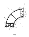
- FIG. 3 shows a cross section through the device according to FIG. 1 with cover elements 8, 9, wherein the first cover 8 in its lateral edge regions on a Side is received by a first fastening element 6 of the first connection element 3 and on an opposite second side by a second first fastening element 6 of the second connection element 4.
- the first cover element 8 extends over the first side 1 of the first wall 10 between the two first fastening elements 6.
- the connection is realized by a plurality of integrally formed together central webs 5.
Landscapes
- Connection Of Plates (AREA)
Abstract
Bauelement, insbesondere Profil zur Verbindung von insbesondere winklig zueinander angeordneten Teilelementen von Gerüsten, Wänden, Gestellen, Möbeln oder dergleichen, aufweisend ein im Wesentlichen geschlossener Querschnitt, welcher sich entlang einer Längsachse (L) erstreckt und ein Hohlprofil bildet, welches in der Längsrichtung (L) stimseitig offen und quer zur Längsrichtung (L) seitlich geschlossen ist, wobei der Querschnitt mindestens zwei freien Enden aufweist, welche jeweils ein Anschlusselement (3, 4) umfassen, wobei die Anschlusselemente (3, 4) durch sich im Wesentlichen gegenüberliegende Wände (10, 20) miteinander verbunden sind, wobei an den Anschlusselementen (3, 4) Befestigungselemente (6, 7) zur Aufnahme von Randbereichen von Abdeckelementen (8, 9) angeordnet sind, wobei sich die Abdeckelemente (8, 9) über mindestens einen Wesentlichen Teil der sich im Wesentlichen gegenüberliegenden Wände (10, 20) zwischen den an diesen Wänden (10, 20) anschliessenden Befestigungselementen (6, 7) erstrecken.Component, in particular profile for connecting in particular angularly arranged to each other sub-elements of scaffolds, walls, frames, furniture or the like, comprising a substantially closed cross-section which extends along a longitudinal axis (L) and forms a hollow profile, which in the longitudinal direction (L ) is open on the end side and laterally closed transversely to the longitudinal direction (L), the cross section having at least two free ends, which each comprise a connection element (3, 4), wherein the connection elements (3, 4) are formed by walls (10 , 20) are connected to each other, wherein on the connecting elements (3, 4) fastening elements (6, 7) for receiving edge regions of cover elements (8, 9) are arranged, wherein the cover elements (8, 9) over at least a substantial part the substantially opposing walls (10, 20) between the at these walls (10, 20) adjoining fastening Hinge elements (6, 7) extend.
Description
Die vorliegende Erfindung betrifft ein Bauelement, insbesondere ein Profil zur Verbindung von insbesondere winklig zueinander angeordneten Teilelementen von Gerüsten, Wänden, Gestellen, Möbeln oder dergleichen.The present invention relates to a component, in particular a profile for connecting in particular at an angle to each other arranged sub-elements of scaffolding, walls, racks, furniture or the like.
Die
Alternativ können Eckprofile, wie in der
Es ist daher eine Aufgabe der Erfindung, ein Bauelement, insbesondere Profil zur Verbindung von insbesondere winklig zueinander angeordneten Teilelementen von Gerüsten, Wänden, Gestellen, Möbeln oder dergleichen, zur Verfügung zu stellen, welches eine verbesserte Befestigung von Abdeckelementen erlaubt. Diese kann insbesondere eine weniger sichtbare Befestigung sein.It is therefore an object of the invention to provide a component, in particular profile for connecting in particular angularly arranged to each other sub-elements of scaffolds, walls, racks, furniture or the like, is available, which allows improved attachment of cover elements. This can be in particular a less visible attachment.
Diese Aufgabe löst ein erfindungsgemässes Bauelement, insbesondere Profil zur Verbindung von insbesondere winklig zueinander angeordneten Teilelementen von Gerüsten, Wänden, Gestellen, Möbeln oder dergleichen. Das Bauelement weist einen im Wesentlichen geschlossenen Querschnitt auf, welcher sich entlang einer Längsachse erstreckt und ein Hohlprofil bildet, welches in der Längsrichtung stirnseitig offen und quer zur Längsrichtung seitlich geschlossen ist. Der Querschnitt weist mindestens zwei freien Enden auf, welche jeweils ein Anschlusselement umfassen, wobei die Anschlusselemente von mindestens zwei freien Enden durch sich im Wesentlichen gegenüberliegende Wände miteinander verbunden sind.This object is achieved by a component according to the invention, in particular a profile for connecting sub-elements of scaffolds, walls, racks, furniture or the like which are arranged in particular at an angle to one another. The component has a substantially closed cross-section, which extends along a longitudinal axis and forms a hollow profile, which is open in the longitudinal direction at the end and laterally closed transversely to the longitudinal direction. The cross-section has at least two free ends, which each comprise a connection element, wherein the connection elements of at least two free ends are connected to each other by substantially opposite walls.
An den Anschlusselementen sind Befestigungselemente zur Aufnahme von Randbereichen von Abdeckelementen angeordnet, wobei sich die Abdeckelemente über mindestens einen Wesentlichen Teil der sich im Wesentlichen gegenüberliegenden Wände zwischen den an diesen Wänden anschliessenden Befestigungselementen erstrecken. Diese Bauweise bietet den Vorteil, dass die Abdeckelemente einfacher ausgebildet sein können, da sie keine Befestigungselemente aufweisen müssen. Es können einfache Platten sein.Fastening elements for receiving edge regions of cover elements are arranged on the connection elements, wherein the cover elements extend over at least a substantial part of the essentially opposite walls between the fastening elements adjoining these walls. This design has the advantage that the cover can be made simpler, since they need not have fasteners. They can be simple plates.
Vorzugsweise sind die Befestigungselemente an Wänden der Anschlusselemente angeordnet. Diese Anordnung ist vorteilhaft, da so die Randbereiche der Abdeckelemente aufgenommen werden können, um zumindest einen Wesentlichen Teil der sich im Wesentlichen gegenüberliegenden Wände zwischen den an diesen Wänden anschliessenden Befestigungselementen abzudecken. Eine Anordnung der Befestigungselemente, beispielsweise in einem zentralen Bereich der sich im Wesentlichen gegenüberliegenden Wände ist grundsätzlich auch möglich, hat jedoch den Nachteil, dass entweder ein darin aufnehmbares Abdeckelement komplizierter ausgebildet sein müsste oder dass diese Befestigungselemente im zentralen Bereich gut sichtbar wären.Preferably, the fastening elements are arranged on walls of the connection elements. This arrangement is advantageous, since in this way the edge regions of the cover elements can be accommodated in order to cover at least a substantial part of the essentially opposite walls between the fastening elements adjoining these walls. An arrangement of the fastening elements, for example, in a central region of the substantially opposite walls is also possible in principle, but has the disadvantage that either a cover element which can be accommodated therein should be made more complicated or that these fastening elements would be clearly visible in the central area.
In einer bevorzugten Ausführungsform sind die Befestigungselemente einstückig mit den Wänden der Anschlusselemente ausgebildet. Dies hat den Vorteil, dass die Befestigungselemente gleichzeitig mit dem gesamten Bauelement hergestellt werden können, was die Produktion vereinfacht und somit Kosten reduziert. Bei einer einstückigen Bauweise ist auch kein zusätzlicher Aufwand für die Montage nötig, was die Montagekosten reduziert.In a preferred embodiment, the fastening elements are formed integrally with the walls of the connection elements. This has the advantage that the fasteners can be made simultaneously with the entire device, which the Simplified production and thus reduced costs. In a one-piece design, no additional effort for the assembly is necessary, which reduces installation costs.
In einer weiteren bevorzugten Ausführungsform sind die Befestigungselemente an den Wänden der Anschlusselemente befestigbar. Dies bietet die Möglichkeit ein gleiches Bauelement mit beispielsweise unterschiedlich dicken Abdeckelementen zu verwenden, wobei lediglich die Halteelemente an das entsprechende Abdeckelement anzupassen sind.In a further preferred embodiment, the fastening elements can be fastened to the walls of the connection elements. This offers the possibility of using an identical component with, for example, differently thick cover elements, wherein only the retaining elements are to be adapted to the corresponding cover element.
Vorzugsweise bilden die sich im Wesentlichen gegenüberliegenden Wände Wände von den Anschlusselementen oder gehen nahtlos in diese über. Dies bietet den Vorteil einer möglichst einfachen Herstellung der Bauelemente. Zusätzliche Absätze oder Versetzungen bedingen kompliziertere Formen während der Herstellung. Ebenfalls sind durch solche Absätze oder Versetzungen grössere Kräfte in der Herstellung nötig, beispielsweise während einem Strangpressverfahren.Preferably, the substantially opposite walls form walls of the connection elements or merge seamlessly into these. This offers the advantage of the simplest possible manufacture of the components. Additional paragraphs or dislocations require more complicated shapes during manufacture. Likewise, such heels or dislocations necessitate greater forces in the production, for example during an extrusion process.
In einer bevorzugten Ausführungsform bilden die Befestigungselemente mit den sich im Wesentlichen gegenüberliegenden Wänden Klemmspalte, in welche die Randbereiche der Abdeckelemente einführbar sind. Dadurch wird eine sichere Befestigung der Abdeckelemente zur Verfügung gestellt, ohne dass viel zusätzliches Material für die Befestigungselemente benötigt wird.In a preferred embodiment, the fastening elements with the substantially opposing walls form clamping gaps into which the edge regions of the cover elements can be inserted. Thereby, a secure attachment of the cover is provided without much additional material for the fasteners is needed.
Vorzugsweise sind die sich im Wesentlichen gegenüberliegenden Wände so ausgestaltet, dass das Bauelement eine gerade, gekrümmte oder segmentierte Form aufweist. Dadurch werden flexibel einsetzbare Bauelemente zur Verfügung gestellt, womit sich eine Vielzahl von Teilelementen von Gerüsten, Wänden, Gestellen, Möbeln oder dergleichen miteinander verbinden lassen.Preferably, the substantially opposing walls are configured so that the component has a straight, curved or segmented shape. As a result, flexibly usable components are provided, which can be a variety of sub-elements of scaffolding, walls, racks, furniture or the like connect to each other.
Bevorzugt weist jedes Anschlusselement jeweils zwischen den zwei sich gegenüberliegenden Wänden eine im Wesentlichen ebene Seitenwand auf, welche parallel oder winklig zu der Seitenwand eines anderen Anschlusselements angeordnet ist. Damit lässt sich eine Grosse Variantenvielfalt von Verbindungen realisieren. Die parallele Anordnung der Seitenwände zueinander beinhaltet eine lineare Variante, in welche eine Mittelsenkrechte einer ersten Seitenwand kollinear mit derjenigen einer zweiten Seitenwand ausgerichtet ist. Ebenfalls ist eine Variante umfasst, bei welcher die beiden oben erwähnten Mittelsenkrechten parallel versetzt zueinander sind. Im Weiteren ist auch eine Variante mögliche, bei der die sich im Wesentlichen gegenüberliegenden Seiten winklig oder gekrümmt ausgebildet sind, die jeweiligen Seitenwände jedoch dennoch parallel zueinander sind.Preferably, each connection element in each case between the two opposing walls on a substantially planar side wall, which is arranged parallel or at an angle to the side wall of another connection element. This makes it possible to realize a large variety of connections. The parallel arrangement of the sidewalls with respect to each other includes a linear variant in which a mid-perpendicular of a first sidewall is collinear with that of a second sidewall. Also included is a variant in which the two above-mentioned perpendicular bisectors are offset parallel to each other. In addition, a variant is possible in which the substantially opposite sides are formed angled or curved, the respective side walls, however, are still parallel to each other.
Bei einer winkligen Ausrichtung der Seitenwände zueinander sind wiederum mehrere Ausführungsformen möglich. Beispielsweise eine, bei welche die sich im Wesentlichen gegenüberliegenden Wände gerade ausgebildet sind und die Seitenwände zueinander winklig ausgebildet sind. Dadurch lässt sich beispielsweise ein Versatz von zwei zum Bauelement benachbarten Teilen realisieren. Der Bereich der sich im Wesentlichen gegenüberliegenden Wände des Bauelements kann jedoch auch gekrümmt oder winklig ausgebildet sein und die Mittelsenkrechten der Seitenwände können stetig, beispielsweise kollinear oder tangential, oder unter einem Winkel an diesen Bereich anschliessen.With an angular alignment of the side walls to each other again several embodiments are possible. For example, one in which the substantially opposite walls are formed straight and the side walls are formed at an angle to each other. As a result, for example, an offset of two parts adjacent to the component can be realized. However, the region of the essentially opposite walls of the component can also be curved or angular and the mid-perpendiculars of the side walls can be continuous, for example collinear or tangential, or at an angle to this region.
Bevorzugt weist das Bauelement zwei, drei, vier oder mehr Anschlusselemente auf. Es ist zu erwähnen, dass es sich bei einem Anschlusselement auch um ein Abschlusselement handeln kann, bei welchem anstelle eines weiteren Elements ein stirnseitiges Abdeckelement angebracht werden kann. Dies ermöglicht einen sehr flexiblen Einsatz der Bauelemente zur Verbindung einzelner Teile oder zum Abschluss einer Konstruktion.The component preferably has two, three, four or more connecting elements. It should be mentioned that a connecting element can also be a terminating element, in which instead of a further element, a front-side covering element can be attached. This allows a very flexible use of the components to connect individual parts or to complete a construction.
Vorzugsweise sind die Befestigungselemente derart angeordnet, dass eine, zwei, drei, vier oder mehr der sich im Wesentlichen gegenüberliegenden Wände abdeckbar sind. So kann je nach bedarf eine Wand abgedeckt werden oder nicht. So kann der Einsatz von unnötigen Abdeckelementen vermieden werden, was sich positiv auf die Lebensdauer der Abdeckelemente auswirkt.Preferably, the fastening elements are arranged such that one, two, three, four or more of the substantially opposite walls can be covered. So can be covered depending on the needs of a wall or not. Thus, the use of unnecessary cover elements can be avoided, which has a positive effect on the life of the cover.
Bevorzugt ist das Bauelement aus Metall, beispielsweise Aluminium oder Stahl, aus Buntmetall, beispielsweise Kupfer oder Messing, oder aus Kunststoff oder verstärktem Kunststoff. Dadurch lässt sich das Bauelement vielseitig einsetzen und kann optimal auf die Umgebung abgestimmt werden.The component is preferably made of metal, for example aluminum or steel, of non-ferrous metal, for example copper or brass, or of plastic or reinforced plastic. As a result, the device can be used in many ways and can be optimally adapted to the environment.
In einer bevorzugten Ausführungsform ist das Bauelement stabförmig ausgebildet und die Ausdehnung des Bauelements in der Längsrichtung beträgt ein Vielfaches der Distanz zwischen den Anschlusselementen. Selbstverständlich lässt sich das Bauelement auch so gestalten, dass die Ausdehnung in der Längsrichtung gleich gross oder kleiner wie die Distanz zwischen den Anschlusselementen ist.In a preferred embodiment, the component is rod-shaped and the extension of the component in the longitudinal direction is a multiple of the distance between the connection elements. Of course, the component can also be designed so that the extension in the longitudinal direction is equal to or smaller than the distance between the connection elements.
Vorzugsweise sind am Bauelement Halterungen zur Aufnahme von stirnseitigen Abdeckelementen oder deren Befestigungselemente vorgesehen. Dadurch lassen sich die stirnseitigen Abdeckelemente einfach und sicher montieren. Die Halterungen sind vorzugsweise einstückig mit dem Bauelement ausgebildet, können aber auch an diesem anbringbar sein.Preferably, brackets for receiving front-side cover elements or their fastening elements are provided on the component. As a result, the frontal cover elements can be mounted easily and safely. The brackets are preferably formed integrally with the component, but can also be attached to this.
Bevorzugt sind die sich im Wesentlichen gegenüberliegenden Wände durch Stege miteinander verbunden. Dies erhöht einerseits die Stabilität und bietet andererseits die Möglichkeit an diesen Stegen oder mit diesen Stegen funktionale Strukturen zu bilden. So können beispielsweise Schäfte für die Aufnahme von Verbindungselementen gemeinsam einstückig mit einem Steg ausgebildet sein. Durch diese Verbindungselemente lassen sich dann beispielsweise zwei Bauelemente in Richtung der Längsachse miteinander verbinden. Die Stege können auch zur Aufteilung des Innenraumes des Bauelements benutzt werden, um beispielsweise Kabelkanäle oder dergleichen zu begrenzen.Preferably, the substantially opposite walls are interconnected by webs. On the one hand, this increases the stability and, on the other hand, offers the possibility of forming functional structures on these webs or with these webs. For example, shanks for receiving connecting elements can be formed integrally with a web. By means of these connecting elements, two components can then be connected to one another in the direction of the longitudinal axis, for example. The webs can also be used to divide the interior of the device, for example, to limit cable channels or the like.
In einer bevorzugten Ausführungsform weisen die Seitenwände mindestens eine Nut auf. Beispielsweise kann eine Seitenwand zwei, drei, vier oder mehr Nuten aufweisen. Alternativ, beispielsweise für ein Abschlusselement, kann die Seitenwand nutlos sein und einen Abschluss nach aussen bilden.In a preferred embodiment, the side walls have at least one groove. For example, one sidewall may have two, three, four or more grooves. Alternatively, for example, for a closure element, the side wall can be without a groove and form a degree to the outside.
Weitere Ausführungsformen sind in den abhängigen Ansprüchen angegeben.Further embodiments are given in the dependent claims.
Bevorzugte Ausführungsformen der Erfindung werden im Folgenden anhand der Zeichnungen beschrieben, die lediglich zur Erläuterung dienen und nicht einschränkend auszulegen sind. In den Zeichnungen zeigen:
- Fig. 1
- eine perspektivische Darstellung einer ersten Ausführungsform eines erfindungsgemässen Bauelements;
- Fig. 2
- eine perspektivische Darstellung einer zweiten Ausführungsform eines erfindungsgemässen Bauelements;
- Fig. 3
- einen Querschnitt durch das
Bauelement gemäss Figur 1 mit Abdeckelementen; - Fig. 4
- einen Querschnitt durch das
Bauelement gemäss Figur 2 mit Abdeckelementen; - Fig. 5
- einen Querschnitt durch eine dritte Ausführungsform eines erfindungsgemässen Bauelements mit Abdeckelementen;
- Fig. 6
- einen Querschnitt durch eine vierte Ausführungsform eines erfindungsgemässen Bauelements mit Abdeckelementen;
- Fig. 7
- einen Querschnitt durch eine fünfte Ausführungsform eines erfindungsgemässen Bauelements mit Abdeckelementen;
- Fig. 8
- eine erste alternative Befestigung der Abdeckelemente an einem erfindungsgemässen Bauelement;
- Fig. 9
- eine zweite alternative Befestigung der Abdeckelemente an einem erfindungsgemässen Bauelement; und
- Fig. 10
- eine dritte alternative Befestigung der Abdeckelemente an einem erfindungsgemässen Bauelement.
- Fig. 1
- a perspective view of a first embodiment of a device according to the invention;
- Fig. 2
- a perspective view of a second embodiment of a device according to the invention;
- Fig. 3
- a cross section through the device according to
FIG. 1 with cover elements; - Fig. 4
- a cross section through the device according to
FIG. 2 with cover elements; - Fig. 5
- a cross section through a third embodiment of a device according to the invention with cover elements;
- Fig. 6
- a cross section through a fourth embodiment of a device according to the invention with cover elements;
- Fig. 7
- a cross-section through a fifth embodiment of a device according to the invention with cover elements;
- Fig. 8
- a first alternative attachment of the cover to a device according to the invention;
- Fig. 9
- a second alternative attachment of the cover to a device according to the invention; and
- Fig. 10
- a third alternative attachment of the cover to a device according to the invention.
Die
Das Bauelement weist eine erste Seite 1 und eine zweite Seite 2 auf, welche in der
An jedem der beiden Anschlusselemente 3, 4 sind hier zwei Befestigungselemente 6, 7 angeordnet. Ein erstes Befestigungselement 6 auf der ersten Seite 1 und ein zweites Befestigungselement 7 auf der zweiten Seite 2.At each of the two
Die Befestigungselemente 6, 7 sind gemeinsam einstückig mit den Anschlusselementen 3, 4 und den sich im Wesentlichen gegenüberliegenden Wänden 10, 20 ausgebildet, wobei das erste Befestigungselement 6 gemeinsam mit einer ersten Wand 10, und das zweite Befestigungselement 7 gemeinsam mit einer zweiten Wand 20 ausgebildet ist.The
Die erste Wand 10 bildet eine Wand der Anschlusselemente 3, 4 und die zweite Wand 20 bildet eine der ersten Wand 10 gegenüberliegende Wand der Anschlusselemente 3, 4.The
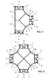
Die
Wie im in der ersten Ausführungsform sind die Anschlusselemente 3, 4 durch sich im Wesentlichen gegenüberliegende Wände 10, 20 miteinander verbunden. Wie bei der ersten Ausführungsform sind die ersten Wände 10 gekrümmt ausgebildet. Im Unterschied zur ersten Ausführungsform ist die zweite Wand 20 gerade ausgebildet, wobei jede erste Wand 10 ein erstes Anschlusselement 3 mit einem zweiten Anschlusselement 4 verbindet und wobei die zweite Wand 20 die beiden zweiten Anschlusselemente 4 miteinander verbindet.As in the first embodiment, the
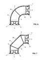
Die
Ähnlich wie auf der ersten Seite 1 erstreckt sich das zweite Abdeckelement 9 auf der zweiten Seite 2 über die zweite Wand 20 zwischen den beiden zweiten Befestigungselementen 7.Similar to the
Die Abdeckelemente 8 und 9 liegen auf den jeweiligen Wänden 10 bzw. 20 auf.The
Das erste Anschlusselement 3 wird im Wesentlichen durch vier Wände gebildet, wobei eine Wand eine Fortsetzung der ersten Wand 10 ist und eine dieser Wand gegenüberliegende Wand eine Fortsetzung der zweiten Wand 20 ist. Ein erster Seitensteg 33 bildet eine gegen den Innenraum I gerichtete Wand des ersten Anschlusselements 3 und eine erste Seitenwand 30, welche dem ersten Seitensteg 33 gegenüberliegend angeordnet ist, bildet eine seitlich gerichtete Wand des ersten Anschlusselements 3. Analog gilt das Gleiche für das zweite Anschlusselement 4 mit seinem zweiten Seitensteg 43 und seiner zweiten Seitenwand 40.The
Die erste Seitenwand 30 weist eine erste hinterschnittene Nut 31 auf, welche zur Aufnahme von Anschluss- oder Verbindungselementen dient, mit welchen das Bauelement mit einem angrenzenden Element verbunden werden kann und die zweite Seitenwand 40 weist eine analoge zweite hinterschnittene Nut 41 auf.The
Im Innern des ersten Anschlusselements 3 ist ein erster Schaft 32 angeordnet. Der erste Schaft 32 wird auf seiner gegen den Innenraum I gerichteten Seite durch den ersten Seitensteg 33 begrenzt und begrenzt mit seiner auf der gegenüberliegenden Seit angeordneten Wand die erste Nut 31 auf ihrer gegen den Innenraum I gerichteten Seite. Diese beiden Wände sind durch Verbindungswände miteinander verbunden und bilden gemeinsam den ersten Schaft 32. Die Innenseiten der Schaftwände können glatt, strukturiert oder mit einem Gewinde versehen sein. Der erste Schaft 32 dient zur Aufnahme von Profilverbindern, Klemmverbindern, Zapfen oder Stifte, mit welchen stirnseitig angeordnete Abdeckungen oder in Längsrichtung L anschliessende Bauelemente mit dem Bauelement verbunden werden können. Das Gleiche gilt für einen zweiten Schaft 42 des zweiten Anschlusselements 4.In the interior of the
Die gegen die erste Nut 31 gerichtete Wand ist mit ersten Rippen 35 mit der ersten Seitenwand 30 verbunden, wobei die ersten Rippen 35 eine seitliche Begrenzung der ersten Nut 31 bilden. Die ersten Rippen 35 sind winklig, beispielsweise unter einem Winkel von 45 Grad, mit der ersten Seitenwand 30 verbunden. Die erste Seitenwand 30 deckt teilweise den die erste Nut 31 bildenden Raum nach aussen ab, so dass im Innern der ersten Nut 31 ein Hinterschnitt hinter der ersten Seitenwand 30 entsteht. Die Form der ersten Nut 31 erlaubt das einsetzen von T-Nutstein-förmigen Verbindungs-, Befestigungs-, Anschluss- oder Abschlusselementen. Wiederum gilt das Gleiche für das zweite Anschlusselement 4.The directed against the
Im Weiteren weist das erste Anschlusselement 3 erste Halterungen 34 zur Aufnahme von stirnseitig angeordneten Blenden oder Abdeckungen oder deren Befestigungselementen auf. Die ersten Halterungen 34 sind einstückig mit dem ersten Anschlusselement 3, vorzugsweise mit der ersten oder zweiten Wand 10, 20 ausgebildet. Das Innere der ersten Halterungen 34 ist kann glatt, strukturiert oder mit einem Gewinde versehen sein. Das zweite Anschlusselement weist analoge zweite Halterungen 44 auf.Furthermore, the
In einfacheren Ausgestaltungen der Bauelemente können die Wände 33, Halterungen 34, und Schaft 32 weggelassen worden sein. Sofern es sich bei dem Bauelement um einen Abschluss handelt, kann auch die Seitenwand 30 glatt durchgehend sein und keine Nut aufweisen. Üblicherweise wird in einem solchen Fall aber ein Element nach
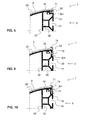
Das erste Anschlusselement 3 weist erste und zweite Befestigungselemente 6, 7 zur Aufnahme von Randbereichen von ersten und zweiten Abdeckelementen 8, 9 auf. Die Befestigungselemente 6, 7 sind gemeinsam einstückig mit dem ersten Anschlusselement 3 ausgebildet. Das zweite Befestigungselement 7 weist im Querschnitt im Wesentlichen eine Hakenform auf, welche durch einen ersten Schenkel 70 und einen zweiten Schenkel 71 gebildet wird. Der erste Schenkel 70 bildet eine Verlängerung der ersten Seitenwand 30 und der zweite Schenkel 71 ist winklig, beispielsweise unter einem Winkel von 90 Grad, am äusseren Ende des ersten Schenkels 70 so angeordnet, dass der zweite Schenkel 71 im Wesentlichen gegen das Innere des Bauelements gerichtet ist. Der zweite Schenkel 71 bildet mit der zweiten Wand 20 einen Klemmspalt, in welchem ein Randbereich des zweiten Abdeckelements 9 aufgenommen werden kann. Analog gilt das Gleiche für das erste Befestigungselement 6, wobei der entsprechende zweite Schenkel einen Klemmspalt mit der ersten Wand 10 bildet. Der Winkel der zweiten Schenkel 71 können auch einen Winkel in Richtung der Seitenwand 20 aufweisen, so dass das freie Ende des Schenkels 71 einen kleineren Abstand von der Seitenwand 20 hat als der Teil des Schenkels 71 nahe am Schenkel 70. Letztendlich bilden die im Querschnitt ein "L" bildenden Schenkel 70 und 71 über die Länge des Bauelementes eine Einschiebenut oder einen Klemmspalt.The
Das erste Abdeckelement 8 ist ein flächiges Element, dessen Abmessungen in Längsrichtung L und in seitlicher Richtung ein Vielfaches seiner Dicke sind. Es handelt sich also umgangssprachlich um eine Platte. Die seitlichen Randbereiche des ersten Abdeckelements 8 sind jeweils seitlich durch ein erstes Befestigungselement 6 gehalten. Das erste Abdeckelement 8 deckt die darunterliegende erste Wand 10 vollständig ab. Alternativ kann die erste Wand nur teilweise abgedeckt sein. Es können auch mehrere unterschiedliche Abdeckelemente verwendet werden um gemeinsam die darunterliegende Wand abzudecken. Die Unterschiede können in der Farbe, dem Material oder der Struktur bestehen. Die Abdeckelemente können eine grössere, eine gleichgrosse oder eine kleinere Abmessung in der Längsrichtung L aufweisen als das Bauelement. Das Gleiche gilt für das zweite Abdeckelement 9 im Zusammenspiel mit den zweiten Befestigungselementen 7 und der zweiten Wand 20. Das Abdeckelement 8 kann auch auf seinen beiden flächigen Seiten unterschiedliche Farben oder Oberflächenstrukturen aufweisen, so dass mit einem Abdeckelement 8 zwei unterschiedliche optische Abdeck-Varianten möglich sind.The
Die
Der Aufbau und die Anordnung der einzelnen Elemente des Bauelements sind ähnlich zu denen der ersten Ausführungsform. Die ersten Wände 10 verbinden ein erstes Anschlusselement 3 mit einem zweiten Anschlusselement 4, wobei die ersten Wände 10, wie vorhin, gekrümmt ausgebildet sind. Die zweie Wand 20 verbindet die beiden zweiten Anschlusselemente 4, wobei die zweite Wand 20 grade ausgebildet ist. Erste Abdeckelemente 8 decken die ersten Wände 10 ab und das zweite Abdeckelement 9 deckt die zweite Wand 20 ab.The structure and the arrangement of the individual elements of the device are similar to those of the first embodiment. The
Im Unterschied zur ersten Ausführungsform, wo der Mittelstege 5 die erste und zweite Wand 10, 20 nicht direkt miteinander verbindet, wird die Verbindung durch mehrere gemeinsam einstückig ausgebildete Mittelstege 5 realisiert.In contrast to the first embodiment, where the
Die
Wie in der zweiten Ausführungsform von
Die
In der in der
Das zweite Abdeckelement 9 weist in seinem Randbereich einen gegen das Bauelement gerichteten Haken 90 auf, welcher im Klemmspalt aufgenommen wird. Der Haken kann über die gesamte flächige Länge des Abdeckelementes 9 bestehen oder nur in ausgewählten Bereichen in Längsrichtung des Bauelements.The
Bei dieser Variante kann die erste und die zweite Wand 10, 20 vollständig, also bis zur vorderen Kante der Wand 30 durch Abdeckelemente 8, 9 verdeckt werden.In this variant, the first and the
Bei dieser Variante können beispielsweise unterschiedlich dicke Abdeckelemente 8,9 zusammen mit einem Bauelement verwendet werden, indem lediglich die Befestigungselemente 6, 7 ausgewechselt werden.In this variant, for example, differently
Bei dieser Variante ist vorteilhaft, dass die Befestigungselemente 6, 7 nach der Verbindung des Bauelements mit einem anschliessenden Bauelement angebracht werden können. Dies verhindert, dass die Abdeckelemente während dem Zusammenbau beschädigt werden können. Die Befestigungselemente können unterschiedlich lange erste und zweite Schenkel 70, 71 aufweisen um unterschiedliche Abdeckelemente optimal aufnehmen zu können.In this variant, it is advantageous that the
Ein erfindungsgemässes Bauelement, insbesondere Profil zur Verbindung von insbesondere winklig zueinander angeordneten Teilelementen von Gerüsten, Wänden, Gestellen, Möbeln oder dergleichen, ist ein Bauelement, welches eine verbesserte Befestigung von Abdeckelementen erlaubt.
Claims (15)
Priority Applications (1)
| Application Number | Priority Date | Filing Date | Title |
|---|---|---|---|
| EP14155249.7A EP2907410A1 (en) | 2014-02-14 | 2014-02-14 | Building component, in particular profile for an angled connection of part of elements |
Applications Claiming Priority (1)
| Application Number | Priority Date | Filing Date | Title |
|---|---|---|---|
| EP14155249.7A EP2907410A1 (en) | 2014-02-14 | 2014-02-14 | Building component, in particular profile for an angled connection of part of elements |
Publications (1)
| Publication Number | Publication Date |
|---|---|
| EP2907410A1 true EP2907410A1 (en) | 2015-08-19 |
Family
ID=50112781
Family Applications (1)
| Application Number | Title | Priority Date | Filing Date |
|---|---|---|---|
| EP14155249.7A Withdrawn EP2907410A1 (en) | 2014-02-14 | 2014-02-14 | Building component, in particular profile for an angled connection of part of elements |
Country Status (1)
| Country | Link |
|---|---|
| EP (1) | EP2907410A1 (en) |
Cited By (4)
| Publication number | Priority date | Publication date | Assignee | Title |
|---|---|---|---|---|
| EP3208174A1 (en) * | 2016-02-18 | 2017-08-23 | Wanzl Metallwarenfabrik GmbH | Transport trolley |
| EP3782928A1 (en) * | 2019-08-23 | 2021-02-24 | Jungheinrich Aktiengesellschaft | Stack storage assembly |
| CH718363A1 (en) * | 2021-02-19 | 2022-08-31 | Procon Btw Gmbh | Plastic toe board and connecting piece. |
| DE102021133149A1 (en) | 2021-12-14 | 2023-06-15 | Boge Elastmetall Gmbh | connection arrangement |
Citations (8)
| Publication number | Priority date | Publication date | Assignee | Title |
|---|---|---|---|---|
| DE1940327A1 (en) * | 1969-08-08 | 1971-02-18 | Karl Broecker | Profiled bar for use in the construction and furniture industry |
| BE785776A (en) * | 1971-07-03 | 1972-11-03 | Syma System Gmbh | PROFILED CONSTRUCTION ELEMENT AND ADDITIONAL ELEMENTS WITH A CROSS-SECTION IN RECTANGULAR SUBSTANCE |
| DE2133355A1 (en) | 1971-07-05 | 1973-01-25 | Syma System Gmbh | ROD-SHAPED COMPONENT WITH A PRINCIPALLY RECTANGULAR CROSS-SECTION |
| EP0013516A1 (en) * | 1979-01-16 | 1980-07-23 | Charles Reith | Apertured upright section with removable cover-plates |
| GB2107176A (en) * | 1981-10-09 | 1983-04-27 | Charles Reith | Tubular section for supporting shelves |
| DE3211404A1 (en) | 1982-03-27 | 1983-09-29 | Manfred-Josef 4330 Mülheim Poggel | Corner profile structural element |
| WO2012052530A1 (en) | 2010-10-22 | 2012-04-26 | Syma Intercontinental Ag | Frame profile system |
| GB2499638A (en) * | 2012-02-24 | 2013-08-28 | Rtd Engineering Ltd | Multi-faced grooved structural element |
-
2014
- 2014-02-14 EP EP14155249.7A patent/EP2907410A1/en not_active Withdrawn
Patent Citations (8)
| Publication number | Priority date | Publication date | Assignee | Title |
|---|---|---|---|---|
| DE1940327A1 (en) * | 1969-08-08 | 1971-02-18 | Karl Broecker | Profiled bar for use in the construction and furniture industry |
| BE785776A (en) * | 1971-07-03 | 1972-11-03 | Syma System Gmbh | PROFILED CONSTRUCTION ELEMENT AND ADDITIONAL ELEMENTS WITH A CROSS-SECTION IN RECTANGULAR SUBSTANCE |
| DE2133355A1 (en) | 1971-07-05 | 1973-01-25 | Syma System Gmbh | ROD-SHAPED COMPONENT WITH A PRINCIPALLY RECTANGULAR CROSS-SECTION |
| EP0013516A1 (en) * | 1979-01-16 | 1980-07-23 | Charles Reith | Apertured upright section with removable cover-plates |
| GB2107176A (en) * | 1981-10-09 | 1983-04-27 | Charles Reith | Tubular section for supporting shelves |
| DE3211404A1 (en) | 1982-03-27 | 1983-09-29 | Manfred-Josef 4330 Mülheim Poggel | Corner profile structural element |
| WO2012052530A1 (en) | 2010-10-22 | 2012-04-26 | Syma Intercontinental Ag | Frame profile system |
| GB2499638A (en) * | 2012-02-24 | 2013-08-28 | Rtd Engineering Ltd | Multi-faced grooved structural element |
Cited By (5)
| Publication number | Priority date | Publication date | Assignee | Title |
|---|---|---|---|---|
| EP3208174A1 (en) * | 2016-02-18 | 2017-08-23 | Wanzl Metallwarenfabrik GmbH | Transport trolley |
| EP3782928A1 (en) * | 2019-08-23 | 2021-02-24 | Jungheinrich Aktiengesellschaft | Stack storage assembly |
| US11596227B2 (en) | 2019-08-23 | 2023-03-07 | Jungheinrich Aktiengesellschaft | Stacking storage arrangement |
| CH718363A1 (en) * | 2021-02-19 | 2022-08-31 | Procon Btw Gmbh | Plastic toe board and connecting piece. |
| DE102021133149A1 (en) | 2021-12-14 | 2023-06-15 | Boge Elastmetall Gmbh | connection arrangement |
Similar Documents
| Publication | Publication Date | Title |
|---|---|---|
| DE102005044980B4 (en) | Butt connector for wood / aluminum facades | |
| EP2907410A1 (en) | Building component, in particular profile for an angled connection of part of elements | |
| EP1580343B1 (en) | Element for the butt joining of profiles | |
| EP1840315B2 (en) | Frame construction | |
| AT510960A4 (en) | LIMIT WALL WITH STEELING DEVICE | |
| EP3315709B1 (en) | Frame profile | |
| DE102016124078B3 (en) | Connecting arrangement for the connection of two control cabinet frame racks | |
| EP2468985B1 (en) | Flooring device for platforms, tribunes, podiums | |
| EP3105483B1 (en) | Clamp | |
| DE202015006861U1 (en) | Protection Profile System | |
| DE19739644C2 (en) | Wall for the cabin of a paint shop | |
| DE102016015791B4 (en) | Connecting arrangement for the connection of two control cabinet frame racks | |
| EP3242981B1 (en) | Quick construction wall | |
| DE202020105836U1 (en) | Holding system and cover system | |
| EP2245318B1 (en) | Connecting junction for profiled elements | |
| EP0443111B1 (en) | Fastener to attach a column to a tubular bar, attached column and assembly with at least a column and a bar | |
| EP1052340A2 (en) | Facade construction with mullion and transom profiles | |
| DE102015100120A1 (en) | Connection and connection device for the connection of frame segments of a frame construction | |
| EP3088815B1 (en) | Air outlet | |
| DE202012008659U1 (en) | Detachable connection between T-shaped overlapping profiles | |
| DE2462536C3 (en) | Connection of a rung profile with a frame profile of a window frame, door frame or the like. | |
| DE20115618U1 (en) | parallel connector | |
| EP0551600A1 (en) | Power unit | |
| DE102014010507A1 (en) | Connection system with additional | |
| DE102013020394B4 (en) | Housing for the installation of screens and / or control panels |
Legal Events
| Date | Code | Title | Description |
|---|---|---|---|
| PUAI | Public reference made under article 153(3) epc to a published international application that has entered the european phase |
Free format text: ORIGINAL CODE: 0009012 |
|
| AK | Designated contracting states |
Kind code of ref document: A1 Designated state(s): AL AT BE BG CH CY CZ DE DK EE ES FI FR GB GR HR HU IE IS IT LI LT LU LV MC MK MT NL NO PL PT RO RS SE SI SK SM TR |
|
| AX | Request for extension of the european patent |
Extension state: BA ME |
|
| 17P | Request for examination filed |
Effective date: 20150901 |
|
| RBV | Designated contracting states (corrected) |
Designated state(s): AL AT BE BG CH CY CZ DE DK EE ES FI FR GB GR HR HU IE IS IT LI LT LU LV MC MK MT NL NO PL PT RO RS SE SI SK SM TR |
|
| 17Q | First examination report despatched |
Effective date: 20180530 |
|
| STAA | Information on the status of an ep patent application or granted ep patent |
Free format text: STATUS: THE APPLICATION IS DEEMED TO BE WITHDRAWN |
|
| 18D | Application deemed to be withdrawn |
Effective date: 20181211 |