EP2907180B1 - Doped nickelate compounds - Google Patents
Doped nickelate compounds Download PDFInfo
- Publication number
- EP2907180B1 EP2907180B1 EP13789884.7A EP13789884A EP2907180B1 EP 2907180 B1 EP2907180 B1 EP 2907180B1 EP 13789884 A EP13789884 A EP 13789884A EP 2907180 B1 EP2907180 B1 EP 2907180B1
- Authority
- EP
- European Patent Office
- Prior art keywords
- metal
- oxidation state
- formula
- cell
- sodium
- Prior art date
- Legal status (The legal status is an assumption and is not a legal conclusion. Google has not performed a legal analysis and makes no representation as to the accuracy of the status listed.)
- Active
Links
- 150000001875 compounds Chemical class 0.000 title claims description 64
- PXHVJJICTQNCMI-UHFFFAOYSA-N Nickel Chemical compound [Ni] PXHVJJICTQNCMI-UHFFFAOYSA-N 0.000 claims description 135
- 239000011572 manganese Substances 0.000 claims description 118
- 239000010936 titanium Substances 0.000 claims description 105
- 239000011777 magnesium Substances 0.000 claims description 96
- 229910001415 sodium ion Inorganic materials 0.000 claims description 83
- 230000003647 oxidation Effects 0.000 claims description 70
- 238000007254 oxidation reaction Methods 0.000 claims description 70
- 239000000463 material Substances 0.000 claims description 68
- 229910052751 metal Inorganic materials 0.000 claims description 66
- 239000002184 metal Substances 0.000 claims description 66
- 238000000034 method Methods 0.000 claims description 60
- 239000011734 sodium Substances 0.000 claims description 59
- 229910052708 sodium Inorganic materials 0.000 claims description 40
- DGAQECJNVWCQMB-PUAWFVPOSA-M Ilexoside XXIX Chemical compound C[C@@H]1CC[C@@]2(CC[C@@]3(C(=CC[C@H]4[C@]3(CC[C@@H]5[C@@]4(CC[C@@H](C5(C)C)OS(=O)(=O)[O-])C)C)[C@@H]2[C@]1(C)O)C)C(=O)O[C@H]6[C@@H]([C@H]([C@@H]([C@H](O6)CO)O)O)O.[Na+] DGAQECJNVWCQMB-PUAWFVPOSA-M 0.000 claims description 39
- 230000008569 process Effects 0.000 claims description 39
- 238000007600 charging Methods 0.000 claims description 38
- VEQPNABPJHWNSG-UHFFFAOYSA-N Nickel(2+) Chemical compound [Ni+2] VEQPNABPJHWNSG-UHFFFAOYSA-N 0.000 claims description 33
- 229910052759 nickel Inorganic materials 0.000 claims description 26
- 229910052760 oxygen Inorganic materials 0.000 claims description 24
- 239000001301 oxygen Substances 0.000 claims description 24
- QVGXLLKOCUKJST-UHFFFAOYSA-N atomic oxygen Chemical compound [O] QVGXLLKOCUKJST-UHFFFAOYSA-N 0.000 claims description 23
- 239000006182 cathode active material Substances 0.000 claims description 16
- 239000010406 cathode material Substances 0.000 claims description 12
- 239000010949 copper Substances 0.000 claims description 12
- 229910052783 alkali metal Inorganic materials 0.000 claims description 11
- 150000001340 alkali metals Chemical class 0.000 claims description 11
- 239000000470 constituent Substances 0.000 claims description 10
- 230000001351 cycling effect Effects 0.000 claims description 7
- 230000002950 deficient Effects 0.000 claims description 7
- 239000002001 electrolyte material Substances 0.000 claims description 7
- 238000004146 energy storage Methods 0.000 claims description 7
- XEEYBQQBJWHFJM-UHFFFAOYSA-N Iron Chemical compound [Fe] XEEYBQQBJWHFJM-UHFFFAOYSA-N 0.000 claims description 6
- KKCBUQHMOMHUOY-UHFFFAOYSA-N Na2O Inorganic materials [O-2].[Na+].[Na+] KKCBUQHMOMHUOY-UHFFFAOYSA-N 0.000 claims description 6
- RYGMFSIKBFXOCR-UHFFFAOYSA-N Copper Chemical compound [Cu] RYGMFSIKBFXOCR-UHFFFAOYSA-N 0.000 claims description 5
- 239000004411 aluminium Substances 0.000 claims description 5
- 229910052782 aluminium Inorganic materials 0.000 claims description 5
- XAGFODPZIPBFFR-UHFFFAOYSA-N aluminium Chemical compound [Al] XAGFODPZIPBFFR-UHFFFAOYSA-N 0.000 claims description 5
- 239000011575 calcium Substances 0.000 claims description 5
- 239000010941 cobalt Substances 0.000 claims description 5
- 229910017052 cobalt Inorganic materials 0.000 claims description 5
- GUTLYIVDDKVIGB-UHFFFAOYSA-N cobalt atom Chemical compound [Co] GUTLYIVDDKVIGB-UHFFFAOYSA-N 0.000 claims description 5
- 229910052802 copper Inorganic materials 0.000 claims description 5
- WPBNNNQJVZRUHP-UHFFFAOYSA-L manganese(2+);methyl n-[[2-(methoxycarbonylcarbamothioylamino)phenyl]carbamothioyl]carbamate;n-[2-(sulfidocarbothioylamino)ethyl]carbamodithioate Chemical compound [Mn+2].[S-]C(=S)NCCNC([S-])=S.COC(=O)NC(=S)NC1=CC=CC=C1NC(=S)NC(=O)OC WPBNNNQJVZRUHP-UHFFFAOYSA-L 0.000 claims description 5
- 239000011701 zinc Substances 0.000 claims description 5
- RTAQQCXQSZGOHL-UHFFFAOYSA-N Titanium Chemical compound [Ti] RTAQQCXQSZGOHL-UHFFFAOYSA-N 0.000 claims description 4
- QCWXUUIWCKQGHC-UHFFFAOYSA-N Zirconium Chemical compound [Zr] QCWXUUIWCKQGHC-UHFFFAOYSA-N 0.000 claims description 4
- 238000007872 degassing Methods 0.000 claims description 4
- 238000004519 manufacturing process Methods 0.000 claims description 4
- 229910052719 titanium Inorganic materials 0.000 claims description 4
- 229910052726 zirconium Inorganic materials 0.000 claims description 4
- 229910052742 iron Inorganic materials 0.000 claims description 3
- OYPRJOBELJOOCE-UHFFFAOYSA-N Calcium Chemical compound [Ca] OYPRJOBELJOOCE-UHFFFAOYSA-N 0.000 claims description 2
- VYZAMTAEIAYCRO-UHFFFAOYSA-N Chromium Chemical compound [Cr] VYZAMTAEIAYCRO-UHFFFAOYSA-N 0.000 claims description 2
- FYYHWMGAXLPEAU-UHFFFAOYSA-N Magnesium Chemical compound [Mg] FYYHWMGAXLPEAU-UHFFFAOYSA-N 0.000 claims description 2
- ZOKXTWBITQBERF-UHFFFAOYSA-N Molybdenum Chemical compound [Mo] ZOKXTWBITQBERF-UHFFFAOYSA-N 0.000 claims description 2
- HCHKCACWOHOZIP-UHFFFAOYSA-N Zinc Chemical compound [Zn] HCHKCACWOHOZIP-UHFFFAOYSA-N 0.000 claims description 2
- 229910052791 calcium Inorganic materials 0.000 claims description 2
- 229910052804 chromium Inorganic materials 0.000 claims description 2
- 239000011651 chromium Substances 0.000 claims description 2
- 229910052749 magnesium Inorganic materials 0.000 claims description 2
- 239000011733 molybdenum Substances 0.000 claims description 2
- 229910052750 molybdenum Inorganic materials 0.000 claims description 2
- 239000011255 nonaqueous electrolyte Substances 0.000 claims description 2
- 229910052706 scandium Inorganic materials 0.000 claims description 2
- SIXSYDAISGFNSX-UHFFFAOYSA-N scandium atom Chemical compound [Sc] SIXSYDAISGFNSX-UHFFFAOYSA-N 0.000 claims description 2
- 229910052720 vanadium Inorganic materials 0.000 claims description 2
- GPPXJZIENCGNKB-UHFFFAOYSA-N vanadium Chemical compound [V]#[V] GPPXJZIENCGNKB-UHFFFAOYSA-N 0.000 claims description 2
- 229910052727 yttrium Inorganic materials 0.000 claims description 2
- VWQVUPCCIRVNHF-UHFFFAOYSA-N yttrium atom Chemical compound [Y] VWQVUPCCIRVNHF-UHFFFAOYSA-N 0.000 claims description 2
- 229910052725 zinc Inorganic materials 0.000 claims description 2
- 229910021385 hard carbon Inorganic materials 0.000 description 30
- GWEVSGVZZGPLCZ-UHFFFAOYSA-N Titan oxide Chemical compound O=[Ti]=O GWEVSGVZZGPLCZ-UHFFFAOYSA-N 0.000 description 24
- 239000003570 air Substances 0.000 description 23
- CDBYLPFSWZWCQE-UHFFFAOYSA-L Sodium Carbonate Chemical compound [Na+].[Na+].[O-]C([O-])=O CDBYLPFSWZWCQE-UHFFFAOYSA-L 0.000 description 22
- NUJOXMJBOLGQSY-UHFFFAOYSA-N manganese dioxide Chemical compound O=[Mn]=O NUJOXMJBOLGQSY-UHFFFAOYSA-N 0.000 description 22
- OKTJSMMVPCPJKN-UHFFFAOYSA-N Carbon Chemical compound [C] OKTJSMMVPCPJKN-UHFFFAOYSA-N 0.000 description 18
- 239000011149 active material Substances 0.000 description 18
- 229910052744 lithium Inorganic materials 0.000 description 18
- 239000002243 precursor Substances 0.000 description 17
- WHXSMMKQMYFTQS-UHFFFAOYSA-N Lithium Chemical compound [Li] WHXSMMKQMYFTQS-UHFFFAOYSA-N 0.000 description 16
- 239000000203 mixture Substances 0.000 description 16
- FKNQFGJONOIPTF-UHFFFAOYSA-N Sodium cation Chemical compound [Na+] FKNQFGJONOIPTF-UHFFFAOYSA-N 0.000 description 15
- 239000011230 binding agent Substances 0.000 description 15
- 229910052799 carbon Inorganic materials 0.000 description 15
- 239000002904 solvent Substances 0.000 description 15
- 229910000008 nickel(II) carbonate Inorganic materials 0.000 description 12
- 229910001416 lithium ion Inorganic materials 0.000 description 11
- 229910000029 sodium carbonate Inorganic materials 0.000 description 11
- BQCIDUSAKPWEOX-UHFFFAOYSA-N 1,1-Difluoroethene Chemical compound FC(F)=C BQCIDUSAKPWEOX-UHFFFAOYSA-N 0.000 description 10
- CSCPPACGZOOCGX-UHFFFAOYSA-N Acetone Chemical compound CC(C)=O CSCPPACGZOOCGX-UHFFFAOYSA-N 0.000 description 10
- 229920006370 Kynar Polymers 0.000 description 10
- 239000003792 electrolyte Substances 0.000 description 10
- 239000002002 slurry Substances 0.000 description 10
- 238000000605 extraction Methods 0.000 description 9
- VTHJTEIRLNZDEV-UHFFFAOYSA-L magnesium dihydroxide Chemical compound [OH-].[OH-].[Mg+2] VTHJTEIRLNZDEV-UHFFFAOYSA-L 0.000 description 9
- 239000000347 magnesium hydroxide Substances 0.000 description 9
- 229910001862 magnesium hydroxide Inorganic materials 0.000 description 9
- RUOJZAUFBMNUDX-UHFFFAOYSA-N propylene carbonate Chemical compound CC1COC(=O)O1 RUOJZAUFBMNUDX-UHFFFAOYSA-N 0.000 description 9
- 238000012360 testing method Methods 0.000 description 8
- 229910018970 NaNi0.5Mn0.5O2 Inorganic materials 0.000 description 6
- XOJVVFBFDXDTEG-UHFFFAOYSA-N Norphytane Natural products CC(C)CCCC(C)CCCC(C)CCCC(C)C XOJVVFBFDXDTEG-UHFFFAOYSA-N 0.000 description 6
- 238000006243 chemical reaction Methods 0.000 description 6
- 239000007772 electrode material Substances 0.000 description 6
- IIPYXGDZVMZOAP-UHFFFAOYSA-N lithium nitrate Chemical compound [Li+].[O-][N+]([O-])=O IIPYXGDZVMZOAP-UHFFFAOYSA-N 0.000 description 6
- 230000002547 anomalous effect Effects 0.000 description 5
- 238000004364 calculation method Methods 0.000 description 5
- 239000011521 glass Substances 0.000 description 5
- 230000007246 mechanism Effects 0.000 description 5
- 150000002739 metals Chemical class 0.000 description 5
- 229920002981 polyvinylidene fluoride Polymers 0.000 description 5
- 239000000047 product Substances 0.000 description 5
- 230000002441 reversible effect Effects 0.000 description 5
- BAZAXWOYCMUHIX-UHFFFAOYSA-M sodium perchlorate Chemical compound [Na+].[O-]Cl(=O)(=O)=O BAZAXWOYCMUHIX-UHFFFAOYSA-M 0.000 description 5
- 229910001488 sodium perchlorate Inorganic materials 0.000 description 5
- 239000000243 solution Substances 0.000 description 5
- 238000000807 solvent casting Methods 0.000 description 5
- KMTRUDSVKNLOMY-UHFFFAOYSA-N Ethylene carbonate Chemical compound O=C1OCCO1 KMTRUDSVKNLOMY-UHFFFAOYSA-N 0.000 description 4
- HBBGRARXTFLTSG-UHFFFAOYSA-N Lithium ion Chemical compound [Li+] HBBGRARXTFLTSG-UHFFFAOYSA-N 0.000 description 4
- PWHULOQIROXLJO-UHFFFAOYSA-N Manganese Chemical compound [Mn] PWHULOQIROXLJO-UHFFFAOYSA-N 0.000 description 4
- -1 Ni2+ ions Chemical class 0.000 description 4
- 238000004458 analytical method Methods 0.000 description 4
- 230000008859 change Effects 0.000 description 4
- 239000013078 crystal Substances 0.000 description 4
- 230000001186 cumulative effect Effects 0.000 description 4
- 150000002500 ions Chemical class 0.000 description 4
- 229910052748 manganese Inorganic materials 0.000 description 4
- 238000002360 preparation method Methods 0.000 description 4
- 230000009467 reduction Effects 0.000 description 4
- 239000007858 starting material Substances 0.000 description 4
- 229910001290 LiPF6 Inorganic materials 0.000 description 3
- IEJIGPNLZYLLBP-UHFFFAOYSA-N dimethyl carbonate Chemical compound COC(=O)OC IEJIGPNLZYLLBP-UHFFFAOYSA-N 0.000 description 3
- 238000007429 general method Methods 0.000 description 3
- 229910002804 graphite Inorganic materials 0.000 description 3
- 239000010439 graphite Substances 0.000 description 3
- 238000005342 ion exchange Methods 0.000 description 3
- 229910001948 sodium oxide Inorganic materials 0.000 description 3
- XKRFYHLGVUSROY-UHFFFAOYSA-N Argon Chemical compound [Ar] XKRFYHLGVUSROY-UHFFFAOYSA-N 0.000 description 2
- IJGRMHOSHXDMSA-UHFFFAOYSA-N Atomic nitrogen Chemical compound N#N IJGRMHOSHXDMSA-UHFFFAOYSA-N 0.000 description 2
- VTYYLEPIZMXCLO-UHFFFAOYSA-L Calcium carbonate Chemical compound [Ca+2].[O-]C([O-])=O VTYYLEPIZMXCLO-UHFFFAOYSA-L 0.000 description 2
- OIFBSDVPJOWBCH-UHFFFAOYSA-N Diethyl carbonate Chemical compound CCOC(=O)OCC OIFBSDVPJOWBCH-UHFFFAOYSA-N 0.000 description 2
- 229910012752 LiNi0.5Mn0.5O2 Inorganic materials 0.000 description 2
- 229910018948 NaNi0.5Ti0.5O2 Inorganic materials 0.000 description 2
- 238000002441 X-ray diffraction Methods 0.000 description 2
- 229910001413 alkali metal ion Inorganic materials 0.000 description 2
- 239000010405 anode material Substances 0.000 description 2
- 239000007864 aqueous solution Substances 0.000 description 2
- 239000007795 chemical reaction product Substances 0.000 description 2
- 238000010277 constant-current charging Methods 0.000 description 2
- 238000007599 discharging Methods 0.000 description 2
- 238000000840 electrochemical analysis Methods 0.000 description 2
- 238000005516 engineering process Methods 0.000 description 2
- 238000002474 experimental method Methods 0.000 description 2
- 238000010438 heat treatment Methods 0.000 description 2
- ZSIAUFGUXNUGDI-UHFFFAOYSA-N hexan-1-ol Chemical compound CCCCCCO ZSIAUFGUXNUGDI-UHFFFAOYSA-N 0.000 description 2
- 238000003780 insertion Methods 0.000 description 2
- 230000037431 insertion Effects 0.000 description 2
- 238000006713 insertion reaction Methods 0.000 description 2
- AMXOYNBUYSYVKV-UHFFFAOYSA-M lithium bromide Chemical compound [Li+].[Br-] AMXOYNBUYSYVKV-UHFFFAOYSA-M 0.000 description 2
- KWGKDLIKAYFUFQ-UHFFFAOYSA-M lithium chloride Chemical compound [Li+].[Cl-] KWGKDLIKAYFUFQ-UHFFFAOYSA-M 0.000 description 2
- 229910003002 lithium salt Inorganic materials 0.000 description 2
- 159000000002 lithium salts Chemical class 0.000 description 2
- 229910000480 nickel oxide Inorganic materials 0.000 description 2
- 239000000843 powder Substances 0.000 description 2
- 239000013077 target material Substances 0.000 description 2
- 229910012406 LiNi0.5 Inorganic materials 0.000 description 1
- 229910016289 MxO2 Inorganic materials 0.000 description 1
- 239000004743 Polypropylene Substances 0.000 description 1
- KEAYESYHFKHZAL-UHFFFAOYSA-N Sodium Chemical compound [Na] KEAYESYHFKHZAL-UHFFFAOYSA-N 0.000 description 1
- 241000364021 Tulsa Species 0.000 description 1
- 239000003513 alkali Substances 0.000 description 1
- WNROFYMDJYEPJX-UHFFFAOYSA-K aluminium hydroxide Chemical compound [OH-].[OH-].[OH-].[Al+3] WNROFYMDJYEPJX-UHFFFAOYSA-K 0.000 description 1
- 229910021502 aluminium hydroxide Inorganic materials 0.000 description 1
- 239000012080 ambient air Substances 0.000 description 1
- 229910052786 argon Inorganic materials 0.000 description 1
- 125000004429 atom Chemical group 0.000 description 1
- 229910000019 calcium carbonate Inorganic materials 0.000 description 1
- 239000002388 carbon-based active material Substances 0.000 description 1
- 238000001816 cooling Methods 0.000 description 1
- 230000007547 defect Effects 0.000 description 1
- 238000011038 discontinuous diafiltration by volume reduction Methods 0.000 description 1
- 239000008151 electrolyte solution Substances 0.000 description 1
- 229940021013 electrolyte solution Drugs 0.000 description 1
- 238000011066 ex-situ storage Methods 0.000 description 1
- 230000002349 favourable effect Effects 0.000 description 1
- 229910001679 gibbsite Inorganic materials 0.000 description 1
- 239000003365 glass fiber Substances 0.000 description 1
- 239000002391 graphite-based active material Substances 0.000 description 1
- 238000000227 grinding Methods 0.000 description 1
- 239000012535 impurity Substances 0.000 description 1
- 238000009830 intercalation Methods 0.000 description 1
- 230000002427 irreversible effect Effects 0.000 description 1
- FUJCRWPEOMXPAD-UHFFFAOYSA-N lithium oxide Chemical compound [Li+].[Li+].[O-2] FUJCRWPEOMXPAD-UHFFFAOYSA-N 0.000 description 1
- 229910001947 lithium oxide Inorganic materials 0.000 description 1
- 229910001437 manganese ion Inorganic materials 0.000 description 1
- 238000002844 melting Methods 0.000 description 1
- 230000008018 melting Effects 0.000 description 1
- 238000002156 mixing Methods 0.000 description 1
- 229910001453 nickel ion Inorganic materials 0.000 description 1
- 229910052757 nitrogen Inorganic materials 0.000 description 1
- 230000001590 oxidative effect Effects 0.000 description 1
- GNRSAWUEBMWBQH-UHFFFAOYSA-N oxonickel Chemical compound [Ni]=O GNRSAWUEBMWBQH-UHFFFAOYSA-N 0.000 description 1
- 125000004430 oxygen atom Chemical group O* 0.000 description 1
- 239000008188 pellet Substances 0.000 description 1
- 229920001155 polypropylene Polymers 0.000 description 1
- 239000007774 positive electrode material Substances 0.000 description 1
- BDERNNFJNOPAEC-UHFFFAOYSA-N propan-1-ol Chemical compound CCCO BDERNNFJNOPAEC-UHFFFAOYSA-N 0.000 description 1
- 238000007086 side reaction Methods 0.000 description 1
- 229910000104 sodium hydride Inorganic materials 0.000 description 1
- 239000012312 sodium hydride Substances 0.000 description 1
- 230000006641 stabilisation Effects 0.000 description 1
- 238000011105 stabilization Methods 0.000 description 1
- 239000003381 stabilizer Substances 0.000 description 1
- 238000001308 synthesis method Methods 0.000 description 1
- 229910052723 transition metal Inorganic materials 0.000 description 1
- 229910000314 transition metal oxide Inorganic materials 0.000 description 1
- 150000003624 transition metals Chemical class 0.000 description 1
- 238000005406 washing Methods 0.000 description 1
- XLYOFNOQVPJJNP-UHFFFAOYSA-N water Substances O XLYOFNOQVPJJNP-UHFFFAOYSA-N 0.000 description 1
- 229910006525 α-NaFeO2 Inorganic materials 0.000 description 1
- 229910006596 α−NaFeO2 Inorganic materials 0.000 description 1
Images


Classifications
-
- H—ELECTRICITY
- H01—ELECTRIC ELEMENTS
- H01M—PROCESSES OR MEANS, e.g. BATTERIES, FOR THE DIRECT CONVERSION OF CHEMICAL ENERGY INTO ELECTRICAL ENERGY
- H01M4/00—Electrodes
- H01M4/02—Electrodes composed of, or comprising, active material
- H01M4/36—Selection of substances as active materials, active masses, active liquids
- H01M4/48—Selection of substances as active materials, active masses, active liquids of inorganic oxides or hydroxides
- H01M4/52—Selection of substances as active materials, active masses, active liquids of inorganic oxides or hydroxides of nickel, cobalt or iron
- H01M4/525—Selection of substances as active materials, active masses, active liquids of inorganic oxides or hydroxides of nickel, cobalt or iron of mixed oxides or hydroxides containing iron, cobalt or nickel for inserting or intercalating light metals, e.g. LiNiO2, LiCoO2 or LiCoOxFy
-
- C—CHEMISTRY; METALLURGY
- C01—INORGANIC CHEMISTRY
- C01G—COMPOUNDS CONTAINING METALS NOT COVERED BY SUBCLASSES C01D OR C01F
- C01G53/00—Compounds of nickel
- C01G53/006—Compounds containing, besides nickel, two or more other elements, with the exception of oxygen or hydrogen
-
- C—CHEMISTRY; METALLURGY
- C01—INORGANIC CHEMISTRY
- C01G—COMPOUNDS CONTAINING METALS NOT COVERED BY SUBCLASSES C01D OR C01F
- C01G53/00—Compounds of nickel
- C01G53/40—Nickelates
-
- C—CHEMISTRY; METALLURGY
- C01—INORGANIC CHEMISTRY
- C01G—COMPOUNDS CONTAINING METALS NOT COVERED BY SUBCLASSES C01D OR C01F
- C01G53/00—Compounds of nickel
- C01G53/40—Nickelates
- C01G53/42—Nickelates containing alkali metals, e.g. LiNiO2
- C01G53/44—Nickelates containing alkali metals, e.g. LiNiO2 containing manganese
- C01G53/50—Nickelates containing alkali metals, e.g. LiNiO2 containing manganese of the type [MnO2]n-, e.g. Li(NixMn1-x)O2, Li(MyNixMn1-x-y)O2
-
- C—CHEMISTRY; METALLURGY
- C01—INORGANIC CHEMISTRY
- C01G—COMPOUNDS CONTAINING METALS NOT COVERED BY SUBCLASSES C01D OR C01F
- C01G53/00—Compounds of nickel
- C01G53/40—Nickelates
- C01G53/66—Nickelates containing alkaline earth metals, e.g. SrNiO3, SrNiO2
-
- H—ELECTRICITY
- H01—ELECTRIC ELEMENTS
- H01M—PROCESSES OR MEANS, e.g. BATTERIES, FOR THE DIRECT CONVERSION OF CHEMICAL ENERGY INTO ELECTRICAL ENERGY
- H01M10/00—Secondary cells; Manufacture thereof
- H01M10/05—Accumulators with non-aqueous electrolyte
- H01M10/054—Accumulators with insertion or intercalation of metals other than lithium, e.g. with magnesium or aluminium
-
- H—ELECTRICITY
- H01—ELECTRIC ELEMENTS
- H01M—PROCESSES OR MEANS, e.g. BATTERIES, FOR THE DIRECT CONVERSION OF CHEMICAL ENERGY INTO ELECTRICAL ENERGY
- H01M4/00—Electrodes
- H01M4/02—Electrodes composed of, or comprising, active material
- H01M4/13—Electrodes for accumulators with non-aqueous electrolyte, e.g. for lithium-accumulators; Processes of manufacture thereof
- H01M4/131—Electrodes based on mixed oxides or hydroxides, or on mixtures of oxides or hydroxides, e.g. LiCoOx
-
- H—ELECTRICITY
- H01—ELECTRIC ELEMENTS
- H01M—PROCESSES OR MEANS, e.g. BATTERIES, FOR THE DIRECT CONVERSION OF CHEMICAL ENERGY INTO ELECTRICAL ENERGY
- H01M4/00—Electrodes
- H01M4/02—Electrodes composed of, or comprising, active material
- H01M4/36—Selection of substances as active materials, active masses, active liquids
- H01M4/48—Selection of substances as active materials, active masses, active liquids of inorganic oxides or hydroxides
- H01M4/50—Selection of substances as active materials, active masses, active liquids of inorganic oxides or hydroxides of manganese
- H01M4/505—Selection of substances as active materials, active masses, active liquids of inorganic oxides or hydroxides of manganese of mixed oxides or hydroxides containing manganese for inserting or intercalating light metals, e.g. LiMn2O4 or LiMn2OxFy
-
- C—CHEMISTRY; METALLURGY
- C01—INORGANIC CHEMISTRY
- C01P—INDEXING SCHEME RELATING TO STRUCTURAL AND PHYSICAL ASPECTS OF SOLID INORGANIC COMPOUNDS
- C01P2002/00—Crystal-structural characteristics
- C01P2002/50—Solid solutions
-
- C—CHEMISTRY; METALLURGY
- C01—INORGANIC CHEMISTRY
- C01P—INDEXING SCHEME RELATING TO STRUCTURAL AND PHYSICAL ASPECTS OF SOLID INORGANIC COMPOUNDS
- C01P2002/00—Crystal-structural characteristics
- C01P2002/70—Crystal-structural characteristics defined by measured X-ray, neutron or electron diffraction data
- C01P2002/72—Crystal-structural characteristics defined by measured X-ray, neutron or electron diffraction data by d-values or two theta-values, e.g. as X-ray diagram
-
- C—CHEMISTRY; METALLURGY
- C01—INORGANIC CHEMISTRY
- C01P—INDEXING SCHEME RELATING TO STRUCTURAL AND PHYSICAL ASPECTS OF SOLID INORGANIC COMPOUNDS
- C01P2006/00—Physical properties of inorganic compounds
- C01P2006/40—Electric properties
-
- H—ELECTRICITY
- H01—ELECTRIC ELEMENTS
- H01M—PROCESSES OR MEANS, e.g. BATTERIES, FOR THE DIRECT CONVERSION OF CHEMICAL ENERGY INTO ELECTRICAL ENERGY
- H01M4/00—Electrodes
- H01M4/02—Electrodes composed of, or comprising, active material
- H01M2004/026—Electrodes composed of, or comprising, active material characterised by the polarity
- H01M2004/028—Positive electrodes
-
- Y—GENERAL TAGGING OF NEW TECHNOLOGICAL DEVELOPMENTS; GENERAL TAGGING OF CROSS-SECTIONAL TECHNOLOGIES SPANNING OVER SEVERAL SECTIONS OF THE IPC; TECHNICAL SUBJECTS COVERED BY FORMER USPC CROSS-REFERENCE ART COLLECTIONS [XRACs] AND DIGESTS
- Y02—TECHNOLOGIES OR APPLICATIONS FOR MITIGATION OR ADAPTATION AGAINST CLIMATE CHANGE
- Y02E—REDUCTION OF GREENHOUSE GAS [GHG] EMISSIONS, RELATED TO ENERGY GENERATION, TRANSMISSION OR DISTRIBUTION
- Y02E60/00—Enabling technologies; Technologies with a potential or indirect contribution to GHG emissions mitigation
- Y02E60/10—Energy storage using batteries
-
- Y—GENERAL TAGGING OF NEW TECHNOLOGICAL DEVELOPMENTS; GENERAL TAGGING OF CROSS-SECTIONAL TECHNOLOGIES SPANNING OVER SEVERAL SECTIONS OF THE IPC; TECHNICAL SUBJECTS COVERED BY FORMER USPC CROSS-REFERENCE ART COLLECTIONS [XRACs] AND DIGESTS
- Y02—TECHNOLOGIES OR APPLICATIONS FOR MITIGATION OR ADAPTATION AGAINST CLIMATE CHANGE
- Y02P—CLIMATE CHANGE MITIGATION TECHNOLOGIES IN THE PRODUCTION OR PROCESSING OF GOODS
- Y02P70/00—Climate change mitigation technologies in the production process for final industrial or consumer products
- Y02P70/50—Manufacturing or production processes characterised by the final manufactured product
-
- Y—GENERAL TAGGING OF NEW TECHNOLOGICAL DEVELOPMENTS; GENERAL TAGGING OF CROSS-SECTIONAL TECHNOLOGIES SPANNING OVER SEVERAL SECTIONS OF THE IPC; TECHNICAL SUBJECTS COVERED BY FORMER USPC CROSS-REFERENCE ART COLLECTIONS [XRACs] AND DIGESTS
- Y10—TECHNICAL SUBJECTS COVERED BY FORMER USPC
- Y10T—TECHNICAL SUBJECTS COVERED BY FORMER US CLASSIFICATION
- Y10T29/00—Metal working
- Y10T29/49—Method of mechanical manufacture
- Y10T29/49002—Electrical device making
- Y10T29/49108—Electric battery cell making
Definitions
- the present invention relates to novel doped nickelate-containing compositions and their method of preparation, to electrodes containing the novel doped nickelate-containing compositions, and to the use of these electrodes, for example in energy storage devices.
- Sodium-ion batteries are analogous in many ways to the lithium-ion batteries that are in common use today; they are both reusable secondary batteries that comprise an anode (negative electrode), a cathode (positive electrode) and an electrolyte material, both are capable of storing energy, and they both charge and discharge via a similar reaction mechanism.
- Na + (or Li + ) ions de-intercalate from the cathode and insert into the anode.
- charge balancing electrons pass from the cathode through the external circuit containing the charger and into the anode of the battery. During discharge the same process occurs but in the opposite direction.
- Lithium-ion battery technology has enjoyed a lot of attention in recent years and provides the preferred portable battery for most electronic devices in use today; however lithium is not a cheap metal to source and is considered too expensive for use in large scale applications.
- sodium-ion battery technology is still in its relative infancy but is seen as advantageous; sodium is much more abundant than lithium and some researchers predict this will provide a cheaper and more durable way to store energy into the future, particularly for large scale applications such as storing energy on the electrical grid. Nevertheless a lot of work has yet to be done before sodium-ion batteries are a commercial reality.
- NaNi 0.5 Mn 0.5 O 2 is a known Na-ion material in which the nickel is present as Ni 2+ while the manganese is present as Mn 4+ . The material is ordered with the Na and Ni atoms residing in discrete sites within the structure.
- the nickel ions (Ni 2+ ) are a redox element which contributes to the reversible specific capacity and the manganese ions (Mn 4+ ) play the role of a structure stabilizer.
- Compound NaNi 0.5 Ti 0.5 O 2 is analogous to NaNi 0.5 Mn 0.5 O 2 in that the Ni 2+ ions provide the active redox centre and the Ti 4+ ions are present for structure stabilization.
- lithium cells where x ⁇ 1 ⁇ 2 are charged to higher voltages, e.g. between 4.5 and 4.7V, they exhibit a long plateau approximately corresponding to 1-2x and subsequent to this plateau, these materials reversibly cycle at capacities over 225mAh/g.
- lithium-containing compounds of the formula Li[Ni x Li (1/3-2x/3) Mn (2/3-x/3) ]O 2 where the amount of nickel is less than 0.5 exhibit a significantly higher charge capacity than would be expected from conventional theoretical calculation.
- Lu and Dahn demonstrated that their lithium materials undergo a non-reversible loss of oxygen when they are charged to higher voltages, and these oxygen deficient materials then react reversibly with lithium. Notwithstanding this, although this increased charge capacity is a potentially interesting discovery, the commercial utility of such compounds is hindered by the high cost of lithium, as discussed above.
- US2007/0218361 teaches a sodium ion secondary battery which comprises a positive electrode active material which includes a sodium-containing transition metal oxide Na a Li b M x O 2 ⁇ .
- the M includes at least two of manganese, iron, cobalt and nickel.
- the amount of sodium is neither too large (otherwise excess sodium oxide or sodium hydride is produced which causes the positive electrode to become highly moisture absorptive) nor too small.
- the amount of sodium ions that can be intercalated and de-intercalated is said to be reduced and this results in a high discharge capacity not being able to be obtained.
- This prior art describes that the optimum amount of sodium, i.e.
- the value of a is preferably 0.6 to 1.1, further preferably 0.9 to 1.1 and more preferably 1.
- the amount of oxygen is also described as critical to performance. Too much oxygen is said to occupy transition metal and/or alkaline metal sites, and presumably this will hinder re-intercalation of the sodium ions during charge/discharge. Too little oxygen is said to produce material with a crystal structure with lots of defects.
- the optimum range for ⁇ is from 0 to 0.1.
- Another feature of the specific examples described in US2007/0218361 is that they all contain manganese in oxidation state +3. This is to allow sodium extraction by a manganese oxidation process (Mn +3 ⁇ Mn 4+ ).
- the present invention aims to provide compounds which are capable of achieving a considerably higher specific charge capacity than would be expected from conventional theoretical calculations. Further, it is desirable for such active compounds to be straightforward to manufacture and easy to handle and store. Further still, the present invention aims to provide a cost effective electrode that comprises one or more of the compounds of the present invention, which is able to be recharged multiple times without significant loss in charge capacity. In particular the present invention will provide an energy storage device that utilises an electrode of the present invention for use in a sodium-ion cell or a sodium metal cell.
- the present invention provides a compound comprising: A a M 1 V M 2 W M 3 X M 4 y M 5 Z O 2-c (Formula 1) wherein
- Preferred compounds of the present invention comprise: A a M 1 V M 2 W M 3 X M 4 y M 5 Z O 2-c (Formula 1) wherein
- Particularly preferred compounds comprise: A a M 1 V M 2 W M 3 X M 4 y M 5 Z O 2-c (Formula 1) wherein
- Metals M 2 and M 4 may be the same or a different metal in oxidation state less than or equal to 4+. Moreover M 2 and M 4 are interchangeable with each other.
- Formula 1 may be written either as: A a M 1 V M 2 W M 3 X M 4 Y M 5 Z O 2-c , or A a M 1 V M 2 W+Y M 3 X M 5 Z O 2-c , or A a M 1 V M 3 X M 4 Y+W M 5 Z O 2-c , and all of these forms of the equation are to be regarded as equivalent.
- M 2 comprises a metal selected from one or more of manganese, titanium and zirconium
- M 3 comprises a metal selected from one or more of magnesium, calcium, copper, zinc and cobalt
- M 4 comprises a metal selected from one or more of manganese, titanium and zirconium
- M 5 comprises a metal selected from one or more of aluminium, iron, cobalt, molybdenum, chromium, vanadium, scandium and yttrium.
- the active compounds of Formula 1 are surprisingly capable of providing a specific charge capacity that is considerably higher than that predicted from conventional theoretical calculations.
- Especially preferred compounds comprise: A a M 1 V M 2 W M 3 X M 4 y M 5 Z O 2-c (Formula 1) wherein
- the active compounds of the present invention may be prepared using any known method. However, a particularly convenient method involves the step of causing a net loss of Na 2 O from one or more active cathode materials of Formula 2, where Formula 2 is defined as A' a' M 1' v' M 2' w' M 3' x' M 4' y' M 5' z' O 2 (Formula 2) wherein
- a highly efficient process of producing compounds of Formula 1 comprises:
- the active cathode materials of Formula 2 are disclosed in Applicant's patent applications GB1212263.6 , GB1212268.5 and GB1212261.0 .
- the process of overcharging involves charging the electrochemical cell containing the one or more active cathode materials to a specific capacity greater than 180mAh/g. Typically this means charging the Na-ion cell to at least 4.2V.
- the overcharging process is the first charge performed on the active materials although it may be possible to charge the active materials to their "normal" specific capacity first and follow this with a process in which the materials are overcharged.
- the present invention therefore provides a method of making an oxygen deficient oxide-containing cathode compound comprising nickel and at least one other metal in an oxidation state greater than 0 to less than or equal to 4+, for use in a Na-ion cell comprising:
- the present invention provides an oxygen deficient oxide-containing cathode compound, for example made using the above method.
- the present invention provides an electrode comprising one or more oxygen deficient oxide-containing cathode compounds, for example made using the above method.
- the mechanism by which oxygen is lost from the active cathode compound during the overcharging process operates most efficiently when the oxide-containing active cathode compound comprises a layered structure.
- Layered A x MO 2 materials are known to adopt several, very similar structural types, the most well-known of which have been categorised by Delmas et al. Physica B+C, 91, (1980), 81 , as "O3, P2 and P3". These notations describe the stacking of the layers; the letter refers to the way in which the oxygen ions are coordinated to the alkali ions, with the letter O denoting an octahedral coordination and the letter P denoting a prismatic coordination. The number refers to the number of MO 2 layers contained in the unit cell.
- the uncharged active cathode materials used in the electrodes of present invention it is preferred that they adopt a layered ⁇ -NaFeO 2 type structure (space group R-3m, no. 166), which has an 03 crystal structure. Following charging, these materials are thought to adopt 03, P2 or P3 or modified versions of these crystal structures, although it is also possible that other crystal structures may be adopted.
- layered active cathode materials for example of Formula 2
- they undergo a structural change which produces a reduction in the volume of the unit cell as compared with both the pristine precursor material, e.g. materials of Formula 2 before charging, and the precursor material after it has been charged to its conventional theoretical capacity, e.g. based on Ni 2+ to Ni 4+ .
- the unit cell volume reduction is consistent with the loss of alkali metal-ions and oxygen loss. This is discussed further below in the relation to the Specific Examples.
- Another characteristic of overcharged oxide-containing cathode compositions is that they appear to lose crystallinity (compared with to the uncharged material); this is shown by the FWHM of the 003 peak of the XRD pattern.
- a determination of when a material is said to be “overcharged” is made by observing the voltage curve for the particular material. At capacities less than or close to the conventional theoretical maximum charge capacity (i.e. the Ni 2+ /Ni 4+ redox couple) a first voltage feature is seen. However the curve continues to rise to a second voltage feature upon further or “over” charging. The materials are said to be “over-charged” from the beginning of this second voltage feature.
- the conventional theoretical maximum charge capacity i.e. the Ni 2+ /Ni 4+ redox couple
- the present invention provides a method of optimising the specific charge capacity of an oxide-containing cathode compound for use in a sodium-ion cell, comprising: charging the composition onto at least a portion of a voltage feature which is observed as a result of the oxide-containing cathode composition being charged above the conventional theoretical maximum charge capacity.
- the present invention also provides a method of optimising the specific charge capacity of an oxide-containing cathode compound according to Formula 1, in a sodium-ion cell comprising:
- discharging compounds of Formula 2 that have been "over-charged" results in producing materials of Formula 1 in which
- the metals M 2 and/or M 4 do not contribute anything to the initial overcharging process, upon discharge of the overcharged material it is found that at least one of the metals M 2 and/or M 4 is also reduced to an oxidation state less than 4+. This allows some or all of the sodium ions that were removed during the first "over-charge" to be reinserted into the material, and therefore produces a material with a higher discharge capacity. It is clear from this description that the role of the Mn 4+ (or Ti 4+ ) in the uncharged materials of the present invention is to allow for the reduction (Na insertion) process during cell discharge. This is in direct contrast to the role of the manganese in US2007/0218361 which is to allow Na extraction by the Mn oxidation process Mn 3+ ⁇ Mn 4+ during the first charge process.
- the role of the M 3 and M 5 metals is to reduce the amount of nickel in the doped nickelate materials of Formula 1, thereby allowing the "over charge” mechanism to take place as oxygen is released from the structure.
- the presence of the M 3 and M 5 metals also reduces the relative formula mass (formula weight) of these materials, thereby further improving the cost effectiveness of the electrode materials.
- oxide-containing cathode compounds When oxide-containing cathode compounds have undergone the over-charge/discharge process described, it is found that they may be cycled in the Na-ion cell between normal voltage limits for the Ni 2+ /Ni 4+ redox couple, typically this might be expected to be between 1 and 4V, and no further unconventional voltage plateaux are formed. Moreover, cycling the over-charged/discharged compositions at normal voltage limits maintains a higher specific capacity than would be expected from conventional theoretical calculations, i.e. the over-charged/discharged oxide-containing cathode compositions perform better than the pristine compounds when cycled using the same normal voltage limits.
- the present invention provides a method of using an oxide-containing cathode compound according to Formula 1 in a Na-ion cell comprising:
- the optimized oxide-containing cathode composition of the present invention may be prepared by a method that does not rely on overcharging a compound of Formula 2.
- the present invention includes an optimised oxide-containing cathode composition made by any route.
- the electrodes according to the present invention are suitable for use in many different applications, for example energy storage devices, rechargeable batteries, electrochemical devices and electrochromic devices.
- the electrodes according to the invention are used in conjunction with a counter electrode and one or more electrolyte materials.
- the electrolyte materials may be any conventional or known materials and may comprise either aqueous electrolyte(s) or non-aqueous electrolyte(s).
- the present invention also provides an energy storage device that utilises an electrode comprising the active oxide containing compounds according to the present invention as described above, and particularly an energy storage device for use as a sodium-ion cell and/or a cell in which sodium is the major mobile ion; a cell in which sodium is the major alkali metal-ion; either of which may be used in a non-aqueous or an aqueous electrolyte system.
- Typical ways to achieve Na to Li-ion exchange include:
- any convenient process may be used to make the precursor materials (Formula 2) described above.
- the following general method may be used:
- ii NaNi 0.40 Mn 0.40 Mg 0.10 Ti 0.10 O 2 Na 2 CO 3 1) Air/800°C, dwell time of 8 hours.
- iii NaNi 0.35 Mn 0.35 Mg 0.15 Ti 0.15 O 2 Na 2 CO 3 1) Air/900°C, dwell time of 8 hours.
- NiCO 3 MnO 2 Mg(OH) 2 TiO 2 2 2 2 2) Air/900°C, dwell time of 8 hours
- Example 1 The Preparation of Ni 0.25 Ti 0.25 Mg 0.25 Mn 0.25 O 1.75
- Active precursor doped nickelate material NaNi 0.25 Ti 0.25 Mg 0.25 Mn 0.25 O 2 (compound xi in Table 1), prepared using the general method described above, was made into a hard carbon anode//NaNi 0.25 Ti 0.25 Mg 0.25 Mn 0.25 O 2 cathode cell using an electrolyte comprising 0.5M NaClO 4 in propylene carbonate, see Figure 1(A)a) . Following a charge process to 230mAh/g, the cathode material was removed from the cell, washed several times in clean dimethyl carbonate and then dried at 70°C.
- Cathode material NaNi 0.25 Ti 0.25 Mg 0.25 Mn 0.25 O 2
- Active Mass of cathode in as-prepared cell 21.5 mg Following the charge process to 230 mAh/g, the cathode electrode disk was removed from the cell, washed several times in clean dimethyl carbonate to remove the electrolyte and then dried at 70°C.
- Example 2 The Preparation of Na a Ni 0.35 Mn 0.35 Mg 0.15 Ti 0.15 O 2-c
- the data shown in Figure 2A, 2B , 2C and 2D are derived from the constant current cycling data for a NaNi 0.35 Mn 0.35 Mg 0.15 Ti 0.15 O 2 (compound iii in Table 1) active precursor cathode material in a Na-ion cell where this cathode material is coupled with a Hard Carbon (Carbotron P/J) anode material.
- the electrolyte used is a 0.5 M solution of NaClO 4 in propylene carbonate.
- the constant current data are collected at an approximate current density of 0.10 mA/cm 2 between voltage limits of 1.50 and 4.20 V. To fully charge the Na-ion cell it, is potentiostatically held at 4.2 V at the end of the constant current charging process.
- the testing is carried out at room temperature.
- sodium-ions are extracted from the cathode active material, and inserted into the Hard Carbon anode.
- sodium-ions are extracted from the Hard Carbon and re-inserted into the cathode active material.
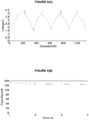
- Figure 2A shows the first four charge-discharge cycles (Na-ion Cell Voltage [V] versus Cumulative Cathode Specific Capacity [mAh/g]) for the Hard Carbon//NaNi 0.35 Mn 0.35 Mg 0.15 Ti 0.15 O 2 cell.
- V Charging Cell Voltage
- mAh/g Cumulative Cathode Specific Capacity
- Figure 2(B) shows the cycle life performance (Cathode Specific Capacity [mAh/g] versus Cycle Number) for a Hard Carbon//NaNi 0.35 Mn 0.35 Mg 0.15 Ti 0.15 O 2 cell.
- the cell shows good reversibility with the delivered cathode specific capacity reaching around 135 mAh/g after 4 cycles.
- Figure 2(C) shows the third cycle discharge voltage profile (Na-ion Cell Voltage [V] versus Cathode Specific Capacity [mAh/g]) for the Hard Carbon//NaNi 0.35 Mn 0.35 Mg 0.15 Ti 0.15 O 2 cell.
- the cathode specific capacity in this cycle corresponds to 130 mAh/g.
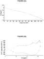
- Figure 2(D) shows the third cycle differential capacity profiles (Differential Capacity [mAh/g/V] versus Na-ion Cell Voltage [V]) for the Hard Carbon//NaNi 0.35 Mn 0.35 Mg 0.15 Ti 0.15 O 2 cell. These symmetrical data demonstrate the excellent reversibility of the ion-insertion reactions in this Na-ion cell.
- the data shown in Figures 3(A), 3(B) , 3(C) and 3(D) are derived from the constant current cycling data for a NaNi 0.35 Mn 0.35 Mg 0.15 Ti 0.15 O 2 (compound iii in Table 1)) active precursor material in a Na-ion cell where this cathode material is coupled with a Hard Carbon (Carbotron P/J) anode material.
- the electrolyte used is a 0.5 M solution of NaClO 4 in propylene carbonate.
- the constant current data are collected at an approximate current density of 0.10 mA/cm 2 between voltage limits of 1.50 V and 4.40 V.
- the Na-ion cell is potentiostatically held at 4.4 V at the end of the constant current charging process.
- the testing is carried out at room temperature.
- sodium ions are extracted from the cathode active material, and inserted into the Hard Carbon anode.
- sodium-ions are extracted from the Hard Carbon and re-inserted into the cathode active material.
- Figure 3(A) shows the first four charge-discharge cycles (Na-ion Cell Voltage [V] versus Cumulative Cathode Specific Capacity [mAh/g]) for the Hard Carbon//NaNi 0.35 Mn 0.35 MG 0.15 Ti 0.15 O 2 cell (Cell#204064).
- V Charging Cell Voltage
- mAh/g Cumulative Cathode Specific Capacity
- Figure 3(B) shows the cycle life performance (Cathode Specific Capacity [mAh/g] versus Cycle Number) for the Hard Carbon//NaNi 0.35 Mn 0.35 Mg 0.15 Ti 0.15 O 2 cell.
- the cell shows good reversibility with the delivered cathode specific capacity reaching around 130 mAh/g after 4 cycles.
- Figure 3(C) shows the third cycle discharge voltage profile (Na-ion Cell Voltage [V] versus Cathode Specific Capacity [mAh/g]) for the Hard Carbon//NaNi 0.35 Mn 0.35 Mg 0.15 Ti 0.15 O 2 cell.
- the cathode specific capacity in this cycle corresponds to 125 mAh/g.
- Figure 3(D) shows the third cycle differential capacity profiles (Differential Capacity [mAh/g/V] versus Na-ion Cell Voltage [V]) for the Hard Carbon//NaNi 0.35 Mn 0.35 Mg 0.15 Ti 0.15 O 2 cell. These symmetrical data demonstrate the excellent reversibility of the ion-insertion reactions in this Na-ion cell.
- the present invention has surprisingly demonstrated that when these sodium-based materials are overcharged, the 'labile' oxygen (which could contribute to thermal runaway) is caused to be removed from the structure; this yields the materials of the present invention which are highly thermodynamically stable and which are extremely effective and safe when used in reversible cathode materials.
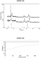
- the XRD operating conditions used to analyse the precursor electrode materials are as follows:
- the XRD operating conditions used for ex-situ analysis of the electrodes are as follows:
- the target materials were tested either i) using a lithium metal anode test cell, or ii) using a Na-ion test cell using a hard carbon anode. It is also possible to test using a Li-ion cell with a graphite anode. Cells may be made using the following procedures:
- the positive electrode is prepared by solvent-casting a slurry of the active material, conductive carbon, binder and solvent.
- the conductive carbon used is Super P (Timcal).
- PVdF co-polymer e.g. Kynar Flex 2801, Elf Atochem Inc.
- acetone is employed as the solvent.
- the slurry is then cast onto glass and a free-standing electrode film is formed as the solvent evaporates.
- the electrode is then dried further at about 80°C.
- the electrode film contains the following components, expressed in percent by weight: 80% active material, 8% Super P carbon, and 12% Kynar 2801 binder.
- an aluminium current collector may be used to contact the positive electrode.
- the electrolyte comprises one of the following: (i) a 1 M solution of LiPF 6 in ethylene carbonate (EC) and dimethyl carbonate (DMC) in a weight ratio of 1:1; (ii) a 1 M solution of LiPF 6 in ethylene carbonate (EC) and diethyl carbonate (DEC) in a weight ratio of 1:1; or (iii) a 1 M solution of LiPF 6 in propylene carbonate (PC)
- a glass fibre separator (Whatman, GF/A) or a porous polypropylene separator (e.g. Celgard 2400) wetted by the electrolyte is interposed between the positive and negative electrodes.
- a Na-ion electrochemical test cell containing the active material is constructed as follows:
- the positive electrode is prepared by solvent-casting a slurry of the active material, conductive carbon, binder and solvent.
- the conductive carbon used is Super P (Timcal).
- PVdF co-polymer e.g. Kynar Flex 2801, Elf Atochem Inc.
- acetone is employed as the solvent.
- the slurry is then cast onto glass and a free-standing electrode film is formed as the solvent evaporates.
- the electrode is then dried further at about 80°C.
- the electrode film contains the following components, expressed in percent by weight: 80% active material, 8% Super P carbon, and 12% Kynar 2801 binder.
- an aluminium current collector may be used to contact the positive electrode.
- the negative electrode is prepared by solvent-casting a slurry of the hard carbon active material (Carbotron P/J, supplied by Kureha), conductive carbon, binder and solvent.
- the conductive carbon used is Super P (Timcal).
- PVdF co-polymer e.g. Kynar Flex 2801, Elf Atochem Inc.
- acetone is employed as the solvent.
- the slurry is then cast onto glass and a free-standing electrode film is formed as the solvent evaporates.
- the electrode is then dried further at about 80°C.
- the electrode film contains the following components, expressed in percent by weight: 84% active material, 4% Super P carbon, and 12% Kynar 2801 binder.
- a copper current collector may be used to contact the negative electrode.
- the positive electrode is prepared by solvent-casting a slurry of the active material, conductive carbon, binder and solvent.
- the conductive carbon used is Super P (Timcal).
- PVdF co-polymer e.g. Kynar Flex 2801, Elf Atochem Inc.
- acetone is employed as the solvent.
- the slurry is then cast onto glass and a free-standing electrode film is formed as the solvent evaporates.
- the electrode is then dried further at about 80°C.
- the electrode film contains the following components, expressed in percent by weight: 80% active material, 8% Super P carbon, and 12% Kynar 2801 binder.
- an aluminium current collector may be used to contact the positive electrode.
- the negative electrode is prepared by solvent-casting a slurry of the graphite active material (Crystalline Graphite, supplied by Conoco Inc.), conductive carbon, binder and solvent.
- the conductive carbon used is Super P (Timcal).
- PVdF co-polymer e.g. Kynar Flex 2801, Elf Atochem Inc.
- acetone is employed as the solvent.
- the slurry is then cast onto glass and a free-standing electrode film is formed as the solvent evaporates.
- the electrode is then dried further at about 80°C.
- the electrode film contains the following components, expressed in percent by weight: 92% active material, 2% Super P carbon, and 6% Kynar 2801 binder.
- a copper current collector may be used to contact the negative electrode.
- the cells are tested as follows, using Constant Current Cycling techniques.
- the cell is cycled at a given current density between pre-set voltage limits.
- a commercial battery cycler from Maccor Inc. (Tulsa, OK, USA) is used.
- On charge sodium (lithium)-ions are extracted from the cathode active material.
- During discharge sodium (lithium)-ions are re-inserted into the cathode active material.
- the c-parameter increases upon charging to 120 mAh/g, and this is due to an increase in repulsion between the electronegative oxygen-ions of adjacent layers, as the sodium-ions are removed.
Description
- The present invention relates to novel doped nickelate-containing compositions and their method of preparation, to electrodes containing the novel doped nickelate-containing compositions, and to the use of these electrodes, for example in energy storage devices.
- Sodium-ion batteries are analogous in many ways to the lithium-ion batteries that are in common use today; they are both reusable secondary batteries that comprise an anode (negative electrode), a cathode (positive electrode) and an electrolyte material, both are capable of storing energy, and they both charge and discharge via a similar reaction mechanism. When a sodium-ion (or lithium-ion battery) is charging, Na+ (or Li+) ions de-intercalate from the cathode and insert into the anode. Meanwhile charge balancing electrons pass from the cathode through the external circuit containing the charger and into the anode of the battery. During discharge the same process occurs but in the opposite direction.
- Lithium-ion battery technology has enjoyed a lot of attention in recent years and provides the preferred portable battery for most electronic devices in use today; however lithium is not a cheap metal to source and is considered too expensive for use in large scale applications. By contrast sodium-ion battery technology is still in its relative infancy but is seen as advantageous; sodium is much more abundant than lithium and some researchers predict this will provide a cheaper and more durable way to store energy into the future, particularly for large scale applications such as storing energy on the electrical grid. Nevertheless a lot of work has yet to be done before sodium-ion batteries are a commercial reality.
- NaNi0.5Mn0.5O2 is a known Na-ion material in which the nickel is present as Ni2+ while the manganese is present as Mn4+. The material is ordered with the Na and Ni atoms residing in discrete sites within the structure. The nickel ions (Ni2+) are a redox element which contributes to the reversible specific capacity and the manganese ions (Mn4+) play the role of a structure stabilizer. Compound NaNi0.5Ti0.5O2 is analogous to NaNi0.5Mn0.5O2 in that the Ni2+ ions provide the active redox centre and the Ti4+ ions are present for structure stabilization. There is plenty of literature describing the preparation of NaNi0.5Mn0.5O2 (and to a lesser extent NaNi0.5Ti0.5O2) as the precursor for making LiNi0.5Mn0.5O2 and LiNi0.5Ti0.5O2 by Na → Li ion exchange for Li-ion applications. A direct synthesis method to make these Li materials yields undesirable disordered materials, for example, as a result of the lithium and nickel atoms sharing structural sites. However, recent electrochemical studies reported by Komaba et al Adv. Funct. Mater. 2011, 21, 3859 describe the sodium insertion performance of hard-carbon and layered NaNi0.5Mn0.5O2 electrodes in propylene carbonate electrolyte solutions. The results obtained show that although NaNi0.5Mn0.5O2 exhibits some reversible charging and discharging ability, the capacity of the material fades by 25% or more, after only 40 cycles.
- It is typically possible to predict the maximum charge capacity for sodium and lithium nickelate compounds based on the Ni2+ to Ni4+ redox process, however as Zhonghua Lu and J. R. Dahn, J. Electrochemical Society, 149 (7) A815-A822 (2002) explain, the electrochemical behaviour of cells made using lithium containing compounds, e.g. Li[NixLi(1/3-2x/3)Mn(2/3-x/3)]O2, where x=1/6, 1/4, 1/3 and 5/12 do not always follow this conventional wisdom. These workers report that when cells containing lithium-nickelate materials are charged at voltages up to 4.45V, this causes lithium to be removed until the Mn oxidation state reaches 4+; thus giving an expected charge capacity of 2x. However, when lithium cells where x < ½ are charged to higher voltages, e.g. between 4.5 and 4.7V, they exhibit a long plateau approximately corresponding to 1-2x and subsequent to this plateau, these materials reversibly cycle at capacities over 225mAh/g. Put simply, lithium-containing compounds of the formula Li[NixLi(1/3-2x/3)Mn(2/3-x/3)]O2 where the amount of nickel is less than 0.5, exhibit a significantly higher charge capacity than would be expected from conventional theoretical calculation. By contrast, Lu and Dahn note that a similar increase in charge capacity is not observed when x = 0.5, i.e. LiNi0.5Mn0.5O2, as there is sufficient nickel present to remove all of the lithium. To explain the higher than expected charge capacity phenomenon, Lu and Dahn demonstrated that their lithium materials undergo a non-reversible loss of oxygen when they are charged to higher voltages, and these oxygen deficient materials then react reversibly with lithium. Notwithstanding this, although this increased charge capacity is a potentially interesting discovery, the commercial utility of such compounds is hindered by the high cost of lithium, as discussed above.
-
US2007/0218361 teaches a sodium ion secondary battery which comprises a positive electrode active material which includes a sodium-containing transition metal oxide NaaLibMxO2±α. The M includes at least two of manganese, iron, cobalt and nickel. In such materials it is apparently extremely important that the amount of sodium is neither too large (otherwise excess sodium oxide or sodium hydride is produced which causes the positive electrode to become highly moisture absorptive) nor too small. In the latter case the amount of sodium ions that can be intercalated and de-intercalated is said to be reduced and this results in a high discharge capacity not being able to be obtained. This prior art describes that the optimum amount of sodium, i.e. the value of a, is preferably 0.6 to 1.1, further preferably 0.9 to 1.1 and more preferably 1. Meanwhile the amount of oxygen is also described as critical to performance. Too much oxygen is said to occupy transition metal and/or alkaline metal sites, and presumably this will hinder re-intercalation of the sodium ions during charge/discharge. Too little oxygen is said to produce material with a crystal structure with lots of defects. The optimum range for α is from 0 to 0.1. Another feature of the specific examples described inUS2007/0218361 is that they all contain manganese in oxidation state +3. This is to allow sodium extraction by a manganese oxidation process (Mn+3→Mn4+). - Prior art document
EP2211405 teaches the use of nickel oxide (NiO) as an electrode material, but there is no disclose that this electrode material also contains another metal. - The present invention aims to provide compounds which are capable of achieving a considerably higher specific charge capacity than would be expected from conventional theoretical calculations. Further, it is desirable for such active compounds to be straightforward to manufacture and easy to handle and store. Further still, the present invention aims to provide a cost effective electrode that comprises one or more of the compounds of the present invention, which is able to be recharged multiple times without significant loss in charge capacity. In particular the present invention will provide an energy storage device that utilises an electrode of the present invention for use in a sodium-ion cell or a sodium metal cell.
- Therefore in a first aspect, the present invention provides a compound comprising:
Aa M1 V M2 W M3 X M4 y M5 Z O2-c (Formula 1)
wherein - A comprises either sodium or a mixed alkali metal in which sodium is the major constituent;
- M1 is nickel in oxidation state greater than 0 to less than or equal to 4+,
- M2 comprises a metal in oxidation state greater than 0 to less than or equal to 4+,
- M3 comprises a metal in
oxidation state 2+, - M4 comprises a metal in oxidation state greater than 0 to less than or equal to 4+, and
- M5 comprises a metal in
oxidation state 3+ - wherein
- 0 ≤ a ≤ 1, preferably 0 ≤ a < 0.5
- v > 0, preferably 0 < v < 0.5
- at least one of w and y is > 0
- x ≥ 0, preferably x > 0
- z ≥ 0
- c > 0.1, preferably 0.1 < c ≤ 0.5
- Preferred compounds of the present invention comprise:
Aa M1 V M2 W M3 X M4 y M5 Z O2-c (Formula 1)
wherein - A comprises either sodium or a mixed alkali metal in which sodium is the major constituent;
- M1 is nickel in
oxidation state 4+, - M2 comprises a metal in
oxidation state 4+, - M3 comprises a metal in
oxidation state 2+, - M4 comprises a metal in
oxidation state 4+, and - M5 comprises a metal in
oxidation state 3+ - wherein
- 0 ≤ a < 1, preferably 0 ≤ a < 0.5
- v > 0, preferably 0 < v < 0.5
- at least one of w and y is > 0
- x ≥ 0, preferably x > 0
- z ≥ 0
- c > 0.1, preferably 0.1 < c ≤ 0.5
- where (a, v, w, x, y, z and c) are chosen to maintain electroneutrality.
- Particularly preferred compounds comprise:
Aa M1 V M2 W M3 X M4 y M5 Z O2-c (Formula 1)
wherein - A comprises either sodium or a mixed alkali metal in which sodium is the major constituent;
- M1 is nickel in oxidation state greater than 0 to less than 4+,
- M2 comprises a metal in oxidation state greater than 0 to less than or equal to 4+,
- M3 comprises a metal in
oxidation state 2+, - M4 comprises a metal in oxidation state greater than 0 to less than or equal to 4+, and
- M5 comprises a metal in
oxidation state 3+ - wherein
- 0 ≤ a ≤ 1, preferably 0 ≤ a < 0.5
- v > 0, preferably 0 < v < 0.5
- at least one of w and y is > 0
- x ≥ 0, preferably x > 0
- z ≥ 0
- c > 0.1, preferably 0.1 < c ≤ 0.5
- where (a, v, w, x, y, z and c) are chosen to maintain electroneutrality.
- Metals M2 and M4 may be the same or a different metal in oxidation state less than or equal to 4+. Moreover M2 and M4 are interchangeable with each other. When M2 = M4 then
Formula 1 may be written either as:
Aa M1 V M2 W M3 X M4 Y M5 Z O2-c,
or
Aa M1 V M2 W+Y M3 X M5 Z O2-c,
or
Aa M1 V M3 X M4 Y+W M5 Z O2-c,
and all of these forms of the equation are to be regarded as equivalent. - Compounds having sodium alone as the chosen alkali metal are especially preferred.
- Preferably, M2 comprises a metal selected from one or more of manganese, titanium and zirconium; M3 comprises a metal selected from one or more of magnesium, calcium, copper, zinc and cobalt; M4 comprises a metal selected from one or more of manganese, titanium and zirconium; and M5 comprises a metal selected from one or more of aluminium, iron, cobalt, molybdenum, chromium, vanadium, scandium and yttrium.
- As discussed below, the active compounds of
Formula 1 are surprisingly capable of providing a specific charge capacity that is considerably higher than that predicted from conventional theoretical calculations. - Especially preferred compounds comprise:
Aa M1 V M2 W M3 X M4 y M5 Z O2-c (Formula 1)
wherein - 0 ≤ a ≤ 1; preferably 0 ≤ a < 0.5; further preferably 0 ≤ a ≤ 0.4; and highly preferably 0.1 ≤ a ≤ 0.4;
- v > 0, preferably 0 < v <0.5;
- 0 < w ≤ 0.5;
- 0 ≤ x < 0.5; preferably 0 < x < 0.5;
- 0 < y < 0.5;
- z ≥ 0; and
- c ≥ 0.11; preferably c ≥ 0.13 and highly preferably c ≥ 0.15, preferably the upper limit for c is ≤ 0.5,
- where a, v, w, x, y, z and c are chosen to maintain electroneutrality.
- In a highly preferred active material of the present invention, (v+w) < 0.8, especially when M2 = Mn and/or Ti.
- Advantageous compounds of the present invention comprise one or more of:
- Ni0.25Ti0.25Mg0.25Mn0.25O1.75;
- Ni0.33Mn0.33Mg0.167Ti0.167O1.83;
- Ni0.33Mn0.33Cu0.167Ti0.167O1.833;
- Ni0.33Mn0.33Zn0.167Ti0.167O1.833;
- Ni0.33Mn0.33Ca0.167Ti0.167O1.833;
- Ni0.35Mn0.35Mg0.15Ti0.15O1.85;
- Ni0.3Mn0.3Mg0.2Ti0.2O1.8;
- Ni0.35Mn0.35Mg0.05Ti0.05Al0.2O1.85;
- Ni0.33Mn0.33Mg0.11Ti0.11Al0.11O1.83;
- Ni0.3Mn0.3Mg0.05Ti0.05Al0.3O1.8;
- Ni0.35Mn0.35Mg0.1Ti0.1Al0.1O1.85;
- Ni0.3Mn0.3Mg0.1Ti0.1Al0.2O1.8;
- Ni0.33Mn0.33Al0.33O1.83;
- Ni0.35Mg0.15Mn0.5O1.85;
- Ni0.333Mg0.167Mn0.5O1.833;
- Ni0.3Mg0.2Mn0.5O1.8;
- Ni0.35Mg0.15Mn0.5O1.85;
- Ni0.3Mg0.2Mn0.5O1.8; and
- Na0.2Ni0.25Ti0.25Mg0.25Mn0.25O1.85;
- The active compounds of the present invention may be prepared using any known method. However, a particularly convenient method involves the step of causing a net loss of Na2O from one or more active cathode materials of
Formula 2, whereFormula 2 is defined as
A'a'M1' v'M2' w'M3' x'M4' y'M5' z'O2 (Formula 2)
wherein - A' comprises either sodium or a mixed alkali metal in which sodium is the major constituent;
- M1' is nickel in
oxidation state 2+, - M2' comprises a metal in
oxidation state 4+, - M3' comprises a metal in
oxidation state 2+, - M4' comprises a metal in
oxidation state 4+, and - M5' comprises a metal in
oxidation state 3+ - 1 ≤ a' < 2;
- 0 < v' < 0.5;
- 0 < w' ≤ 0.5;
- 0 ≤ x' < 0.5;
- 0 ≤ y' < 0.5;
- z' ≥ 0;
- and wherein v', w', x', y' and z' are all chosen to maintain electroneutrality.
- A highly efficient process of producing compounds of
Formula 1 comprises: - charging an electrochemical cell containing one or more active cathode materials of
Formula 2 beyond the conventional theoretical specific capacity as determined by the Ni2+/Ni4+ redox couple; whereinFormula 2 is defined as:
A'a'M1' v'M2' w'M3' x'M4' y'M5' z'O2 (Formula 2)
wherein- A' comprises either sodium or a mixed alkali metal in which sodium is the major constituent;
- M1' is nickel in
oxidation state 2+, - M2' comprises a metal in
oxidation state 4+, - M3' comprises a metal in
oxidation state 2+, - M4' comprises a metal in
oxidation state 4+, and - M5' comprises a metal in
oxidation state 3+ - 1 ≤ a' ≤ 2;
- 0 < v' < 0.5;
- 0 < w' ≤ 0.5;
- 0 ≤ x' < 0.5;
- 0 ≤ y' < 0.5;
- z' ≥ 0;
- and wherein v', w', x', y' and z' are all chosen to maintain electroneutrality.
- The active cathode materials of
Formula 2 are disclosed in Applicant's patent applicationsGB1212263.6 GB1212268.5 GB1212261.0 - The process of overcharging involves charging the electrochemical cell containing the one or more active cathode materials to a specific capacity greater than 180mAh/g. Typically this means charging the Na-ion cell to at least 4.2V. Preferably the overcharging process is the first charge performed on the active materials although it may be possible to charge the active materials to their "normal" specific capacity first and follow this with a process in which the materials are overcharged.
- Charging doped sodium nickelate compounds of
Formula 2 up to their theoretical capacity causes the oxidation of Ni2+ to Ni4+ and the removal of a portion of the sodium ions from the lattice. By contrast, charging such compounds above their conventional theoretical capacity, i.e. "over-charging" them, produces materials ofFormula 1 in which - M1 is nickel in
oxidation state 4+, - M2 comprises a metal in
oxidation state 4+, - M4 comprises a metal in
oxidation state 4+, - 0 ≤ a <1, preferably 0 ≤ a < 0.5 and
- C > 0.1, preferably 0.1 < c ≤ 0.5.
- The enhanced charge capacity (or anomalous charge capacity) observed when materials of
Formula 2 are "over-charged" is due to several changes that occur as the over-charging is taking place. Broadly speaking this is a combination of the conventional (or "normal") charge process using just the oxidation of Ni2+ to Ni4+, together with other structural changes that occur exclusively at the higher voltages, such as the removal of a higher than expected (from conventional theory) number of sodium ions and also an irreversible partial loss of oxygen to yield O2-c-containing active materials. - The present invention therefore provides a method of making an oxygen deficient oxide-containing cathode compound comprising nickel and at least one other metal in an oxidation state greater than 0 to less than or equal to 4+, for use in a Na-ion cell comprising:
- a) forming an electrochemical cell comprising an oxide-containing cathode compound; and
- b) charging the oxide-containing cathode compound in said electrochemical cell to cause the loss of oxygen from the oxide-containing cathode compound and thereby form the oxygen deficient oxide-containing cathode compound.
- Further the present invention provides an oxygen deficient oxide-containing cathode compound, for example made using the above method. Advantageously the present invention provides an electrode comprising one or more oxygen deficient oxide-containing cathode compounds, for example made using the above method.
- The mechanism by which oxygen is lost from the active cathode compound during the overcharging process operates most efficiently when the oxide-containing active cathode compound comprises a layered structure. Layered AxMO2 materials are known to adopt several, very similar structural types, the most well-known of which have been categorised by Delmas et al. Physica B+C, 91, (1980), 81, as "O3, P2 and P3". These notations describe the stacking of the layers; the letter refers to the way in which the oxygen ions are coordinated to the alkali ions, with the letter O denoting an octahedral coordination and the letter P denoting a prismatic coordination. The number refers to the number of MO2 layers contained in the unit cell. In the case of the uncharged active cathode materials used in the electrodes of present invention, it is preferred that they adopt a layered α-NaFeO2 type structure (space group R-3m, no. 166), which has an 03 crystal structure. Following charging, these materials are thought to adopt 03, P2 or P3 or modified versions of these crystal structures, although it is also possible that other crystal structures may be adopted.
- The Applicant has noted that when layered active cathode materials, for example of
Formula 2, are over-charged in a Na-ion cell, they undergo a structural change, which produces a reduction in the volume of the unit cell as compared with both the pristine precursor material, e.g. materials ofFormula 2 before charging, and the precursor material after it has been charged to its conventional theoretical capacity, e.g. based on Ni2+ to Ni4+. It is believed that such unit cell volume reduction is consistent with the loss of alkali metal-ions and oxygen loss. This is discussed further below in the relation to the Specific Examples. Another characteristic of overcharged oxide-containing cathode compositions is that they appear to lose crystallinity (compared with to the uncharged material); this is shown by the FWHM of the 003 peak of the XRD pattern. - A determination of when a material is said to be "overcharged" is made by observing the voltage curve for the particular material. At capacities less than or close to the conventional theoretical maximum charge capacity (i.e. the Ni2+/Ni4+ redox couple) a first voltage feature is seen. However the curve continues to rise to a second voltage feature upon further or "over" charging. The materials are said to be "over-charged" from the beginning of this second voltage feature.
- Therefore the present invention provides a method of optimising the specific charge capacity of an oxide-containing cathode compound for use in a sodium-ion cell, comprising: charging the composition onto at least a portion of a voltage feature which is observed as a result of the oxide-containing cathode composition being charged above the conventional theoretical maximum charge capacity.
- The present invention also provides a method of optimising the specific charge capacity of an oxide-containing cathode compound according to
Formula 1, in a sodium-ion cell comprising: - a) forming a sodium-ion cell comprising an oxide-containing cathode material according to
Formula 2; - b) optionally charging said cell to a cell voltage within the conventional theoretical capacity based on the Ni2+/Ni4+ redox couple;
- c) charging said cell to a cell voltage that results in the active cathode material being charged beyond the conventional theoretical capacity based on the Ni2+/Ni4+ redox couple; and
- d) degassing the Na-ion cell to remove gasses formed during the charging process.
- A doped sodium nickelate of
Formula 2 charged to its theoretical specific capacity limit based on the Ni2+/Ni4+ redox couple, will re-yield a compound with no oxygen loss when discharged; i.e. at this level, charging is seen to be reversible. However, discharging compounds ofFormula 2 that have been "over-charged" results in producing materials ofFormula 1 in which - M1 is nickel in oxidation state less than 4+,
- at least one of M2 and M4 comprises a metal in oxidation state less than 4+,
- 0 < a ≤ 1
- 0 < v < 0.5 and
- c > 0.1, preferably 0.1 < c < 0.5.
- Consequently, during the discharge of over-charged compounds of
Formula 2 the nickel is reduced fromoxidation state 4+ tooxidation state 2+, some or all of the sodium-ions are re-inserted into the lattice and the lost oxygen atoms are not replaced. - Moreover, although the metals M2 and/or M4 do not contribute anything to the initial overcharging process, upon discharge of the overcharged material it is found that at least one of the metals M2 and/or M4 is also reduced to an oxidation state less than 4+. This allows some or all of the sodium ions that were removed during the first "over-charge" to be reinserted into the material, and therefore produces a material with a higher discharge capacity. It is clear from this description that the role of the Mn4+ (or Ti4+) in the uncharged materials of the present invention is to allow for the reduction (Na insertion) process during cell discharge. This is in direct contrast to the role of the manganese in
US2007/0218361 which is to allow Na extraction by the Mn oxidation process Mn3+ → Mn4+ during the first charge process. - The role of the M3 and M5 metals is to reduce the amount of nickel in the doped nickelate materials of
Formula 1, thereby allowing the "over charge" mechanism to take place as oxygen is released from the structure. The presence of the M3 and M5 metals also reduces the relative formula mass (formula weight) of these materials, thereby further improving the cost effectiveness of the electrode materials. In order to achieve anomalous capacity, there must be over twice the amount of sodium as there is nickel in the pristine materials (e.g. Formula 2) so that, when all Ni2+ has oxidised to Ni4+, there is still some Na left in the material, which can then be removed when the material is overcharged and releases oxygen. This explains why anomalous capacity is not observed for NaNi0.5Mn0.5O2; in this case there is enough Ni2+ present to remove all of the Na. In each of the compounds ofFormula 2 where a' = 1, following the requirement above, there has to be less than 0.5 Ni and the overall material must be electroneutral. Satisfaction of these two conditions is facilitated by the presence of an M3 metal, and/or an M5 metal. - When oxide-containing cathode compounds have undergone the over-charge/discharge process described, it is found that they may be cycled in the Na-ion cell between normal voltage limits for the Ni2+/Ni4+ redox couple, typically this might be expected to be between 1 and 4V, and no further unconventional voltage plateaux are formed. Moreover, cycling the over-charged/discharged compositions at normal voltage limits maintains a higher specific capacity than would be expected from conventional theoretical calculations, i.e. the over-charged/discharged oxide-containing cathode compositions perform better than the pristine compounds when cycled using the same normal voltage limits.
- Thus the present invention provides a method of using an oxide-containing cathode compound according to
Formula 1 in a Na-ion cell comprising: - a) forming a Na-ion cell comprising an active oxide-containing cathode material according to
Formula 2; - b) optionally charging said cell to a cell voltage within the conventional theoretical capacity based on the Ni2+/Ni4+ redox couple;
- c) charging said Na-ion cell to a cell voltage beyond the conventional theoretical capacity of the cathode material based on the Ni2+/Ni4+ redox couple;
- d) degassing the Na-ion cell to remove gasses formed during the charging process; and
- e) cycling the resulting Na-ion cell, which now comprises an oxide-containing cathode composition according to
Formula 1, over a voltage range within the normal voltage limits of the Ni2+/Ni4+ redox couple. - As mentioned above, it is envisaged that the optimized oxide-containing cathode composition of the present invention may be prepared by a method that does not rely on overcharging a compound of
Formula 2. Thus the present invention includes an optimised oxide-containing cathode composition made by any route. - The electrodes according to the present invention are suitable for use in many different applications, for example energy storage devices, rechargeable batteries, electrochemical devices and electrochromic devices.
- Advantageously, the electrodes according to the invention are used in conjunction with a counter electrode and one or more electrolyte materials. The electrolyte materials may be any conventional or known materials and may comprise either aqueous electrolyte(s) or non-aqueous electrolyte(s).
- The present invention also provides an energy storage device that utilises an electrode comprising the active oxide containing compounds according to the present invention as described above, and particularly an energy storage device for use as a sodium-ion cell and/or a cell in which sodium is the major mobile ion; a cell in which sodium is the major alkali metal-ion; either of which may be used in a non-aqueous or an aqueous electrolyte system.
- It is also possible to convert sodium-ion derivatives into mixed lithium-ion/sodium-ion materials using an ion exchange process.
- Typical ways to achieve Na to Li-ion exchange include:
- 1. Mixing the sodium-ion material with a lithium-containing material e.g. LiNO3, heating to above the melting point of LiNO3 (264°C), cooling and then washing to remove the excess LiNO3 and side-reaction product
- 2. Treating the Na-ion material with an aqueous solution of lithium salts, for example 1M LiCl in water; and
- 3. Treating the Na-ion material with a non-aqueous solution of lithium salts, for example LiBr in one or more aliphatic alcohols such as hexanol, propanol etc.
- The present invention will now be described with reference to the following figures in which:
-
FIGURE 1(A) is a comparison of XRD profiles for a) the precursor starting material, NaNi0.25Ti0.25Mg0.25Mn0.25O2, b) an electrode, originally containing NaNi0.25Ti0.25Mg0.25Mn0.25O2, recovered from a cell after charging to 120mAh/g and c) an electrode, originally containing NaNi0.25Ti0.25Mg0.25Mn0.25O2 recovered from a cell after charging to 230mAh/g; -
FIGURE 1(B) shows the First Charge Process (Na-ion cell Voltage [V] versus Cathode Specific Charge Capacity [mAh/g]) for a Hard Carbon//NaNi0.25Ti0.25Mg0.25Mn0.25O2 cell using an electrolyte of 0.5M sodium perchlorate in propylene carbonate (PC), charging to 230mAh/g; -
FIGURE 2(A) shows the Charge-Discharge Voltage Profile for the first 4 cycles (Na-ion Cell Voltage [V] versus Cumulative Cathode Specific Capacity [mAh/g]) for a Hard Carbon//NaNi0.35Mn0.35Mg0.15Ti0.15O2 cell, cycled between 1.5 to 4.2V; -
FIGURE 2(B) shows the Cycle Life Performance (Cathode Specific Capacity [mAh/g] versus Cycle Number) for a Hard Carbon// NaNi0.35Mn0.35Mg0.15Ti0.15O2 cell, cycled between 1.5 to 4.2V; -
FIGURE 2(C) shows the Third Cycle Discharge Voltage Profile (Na-ion Cell Voltage [V] versus Cathode Specific Capacity [mAh/g]) for a Hard Carbon//NaNi0.35Mn0.35Mg0.15Ti0.15O2 cell, cycled between 1.5 to 4.2V; -
FIGURE 2(D) shows the Third Cycle Differential Capacity Profiles (Differential Capacity [mAh/g/V]) versus Na-ion Cell voltage [V]) for a Hard Carbon//NaNi0.35Mn0.35Mg0.15Ti0.15O2 cell, cycled between 1.5 to 4.2V; -
FIGURE 3(A) shows the Charge-Discharge Voltage Profiles for the first 4 cycles (Na-ion cell Voltage [V] versus Cumulative Cathode Specific Capacity [mAh/g]) for a Hard Carbon//NaNi0.35Mn0.35Mg0.15Ti0.15O2 cell, cycled between 1.5 to 4.4V; -
FIGURE 3(B) shows the Cycle Life Performance (Cathode Specific Capacity [mAh/g] versus Cycle Number) for a Hard Carbon// NaNi0.35Mn0.35Mg0.15Ti0.15O2 cell, cycled between 1.5 to 4.4V; -
FIGURE 3(C) shows the Third Cycle Discharge Voltage Profile (Na-ion Cell Voltage [V] versus Cathode Specific Capacity [mAh/g]) for a Hard Carbon//NaNi0.35Mn0.35Mg0.15Ti0.15O2 cell, cycled between 1.5 to 4.4V; -
FIGURE 3(D) shows the Third Cycle Differential Capacity Profiles (Differential Capacity [mAh/g/V]) versus Na-ion Cell voltage [V]) for a Hard Carbon//NaNi0.35Mn0.35Mg0.15Ti0.15O2 cell, cycled between 1.5 to 4.4V; -
FIGURE 4(A) shows the changes observed in the a and c cell parameters for NaNi25Ti0.25Mg0.25Mn0.25O2 as pristine material, material charged to 120mAh/g and material charged to 230 mAh/g; and -
FIGURE 4(B) shows the changes in unit cell volume for NaNi25Ti0.25Mg0.25Mn0.25O2 as pristine material, material charged to 120mAh/g and material charged to 230 mAh/g. - Any convenient process may be used to make the precursor materials (Formula 2) described above. For example, the following general method may be used:
-
- 1) Intimately mix together the starting materials in the correct stoichiometric ratio and press into a pellet.
- 2) Heat the resulting mixture in a furnace using either an ambient air atmosphere, or a flowing inert atmosphere (e.g. argon or nitrogen), at a furnace temperature of between 400°C and 1500°C until reaction product forms.
- 3) Allow the product to cool before grinding it to a powder.
- Table 1 below lists the starting materials and heating conditions used to prepare
example precursor materials 1 to 12 ofFormula 2.TABLE 1 PRECURSOR MATERIAL OF FORMULA 2STARTING MATERIALS FURNACE CONDITIONS i NaNi0.45Mn0.45Mg0.05Ti0.05O2 Na2CO3 1) Air/800°C, dwell time of 8 hours. NiCO3 Mg(OH)2 MnO2 2) Air/900°C, dwell TiO2 time of 8 hours. ii NaNi0.40Mn0.40Mg0.10Ti0.10O2 Na2CO3 1) Air/800°C, dwell time of 8 hours. NiCO3 Mg(OH)2 MnO2 TiO2 2) Air/900°C, dwell time of 8 hours. iii NaNi0.35Mn0.35Mg0.15Ti0.15O2 Na2CO3 1) Air/900°C, dwell time of 8 hours. NiCO3 MnO2 Mg(OH)2 TiO2 2) Air/900°C, dwell time of 8 hours. iv NaNi0.30Mr0.30Mg0.20Ti0.20O2 Na2CO3 1) Air/900°C, dwell time of 8 hours NiCO3 MnO2 Mg(OH)2 TiO2 2) Air/900°C, dwell time of 8 hours. v NaNi0.40Ti0.50Mg0.10O2 Na2CO2 1)Air/900°C, dwell time of 8 hours NiCO3 TiO2 Mg(OH)2 2)/900°C, dwell time of 8 hours. vi NaNi0.40Ti0.40Mg0.10Mn0.10O2 Na2CO3 1)Air/900°C, dwell time of 8 hours NiCO3 TiO2, Mg(OH)2 MnO2 2) Air/900°C, dwell time of 8 hours. vii NaNi0.40Mn0.40Mg0.05Ti0.05Al0.1O2 Na2CO3 1) Air/800°C, dwell time of 8 hours NiCO3 Mg(OH)2 MnO2 TiO2 2) Air/900°C, dwell time of 8 hours. Al(OH)3 viii NaNi0.45Mn0.45Cu0.05Ti0.05O2 Na2CO3 1) Air/900°C, dwell time of 8 hours NiCO3 MnO2 CuO TiO2 2) Air/900°C, dwell time of 8 hours. ix NaNi0.40Mn0.40Ca0.10Ti0.10O2 Na2CO3 1) Air/900°C, dwell time of 8 hours NiCO3 MnO2 CaCO3 TiO2 2) Air/900°C, dwell time of 8 hours. 3) Air/950°C, dwell time of 8 hours. x NaNi0.40Mn0.40Zn0.10Ti0.10O2 Na2CO3 1) Air/900°C, dwell time of 8 hours NiCO3 MnO2 CuO TiO2 2) Air/900°C, dwell time of 8 hours. xi NaNi25Ti0.25Mg0.25Mn0.25O2 Na2CO3 1) Air/900°C, dwell time of 8 hours NiCO3 TiO2 Mg(OH)2 MnO2 2) Air/950°C, dwell time of 8 hours xii NaNi0.33Mn0.33Mg0.167Ti0.167O2 Na2CO3 1) Air/900°C, dwell time of 8 hours NiCO3 TiO2, Mg(OH)2 MnO2 - Active precursor doped nickelate material, NaNi0.25Ti0.25Mg0.25Mn0.25O2 (compound xi in Table 1), prepared using the general method described above, was made into a hard carbon anode//NaNi0.25Ti0.25Mg0.25Mn0.25O2 cathode cell using an electrolyte comprising 0.5M NaClO4 in propylene carbonate, see
Figure 1(A)a) . Following a charge process to 230mAh/g, the cathode material was removed from the cell, washed several times in clean dimethyl carbonate and then dried at 70°C. Looking atFigure 1(A)c) , it is clear that the material obtained following the charge process to 230mAh/g is not the same as that shown in eitherFigure 1(A)b) (charged to 120mAh/g) or that shown by the original active precursor doped nickelate material, NaNi0.25Ti0.25Mg0.25Mn0.25O2 (as shown inFigure 1(A)a) . The proposed composition for the product obtained following the charge process to 230mAh/g is Ni0.25Ti0.25Mg0.25Mn0.25O1.75, as determined by the following mass loss experiment.
Mass Loss Experiment to determine the composition of Ni 0.25 Ti 0.25 Mg 0.25 Mn 0.25 O 1.75 .
Cathode material = NaNi0.25Ti0.25Mg0.25Mn0.25O2
Anode = Hard Carbon
Electrolyte = 0.5 M NaClO4 in Propylene Carbonate.
Active Mass of cathode in as-prepared cell = 21.5 mg
Following the charge process to 230 mAh/g, the cathode electrode disk was removed from the cell, washed several times in clean dimethyl carbonate to remove the electrolyte and then dried at 70°C. - The Active Mass of the washed cathode after first charge process shown in
Figure 1(B) = 16.1 mg - Thus the Active Mass loss = (21.5 mg - 16.1 mg) = 5.4 mg which equates to:
- %mass loss = 25.1 %
- If charge process was just by Na-ion extraction then mass loss should be:
Starting composition = NaNi0.25Ti0.25Mg0.25Mn0.25O2
Molecular weight = 101.4 g/mol
Based on only the Ni2+ to Ni4+ redox process, on cell charge it is only possible to extract 0.5 Na-ion per formula unit. i.e.
NaNi0.25Ti0.25Mg0.25Mn0.25O2 → Na0.5Ni0.25Ti0.25Mg0.25Mn0.25O2 + 0.5 Na+ + 0.5 e- (1)
- Therefore, the theoretical capacity based on this reaction (1) may be given by the following: Theoretical Specific Capacity = (0.5 x 96485)/(101.4 x 3.6) = 132 mAh/g
- The charge process as shown in
Figure 1 (B) , corresponds to an actual cathode specific capacity of 230 mAh/g - i.e. far in excess of the expected theoretical specific capacity of 132 mAh/g. - Thus the following overall charge mechanism is:
NaNi0.25Ti0.25Mg0.25Mn0.25O2 → Na0.5Ni0.25Ti0.25Mg0.25Mn0.25O2 + 0.5 Na+ + 0.5 e- (1)
followed by:
Na0.5Ni0.25Ti0.25Mg0.25Mn0.25O2 → Ni0.25Ti0.25Mg0.25Mn0.25O1.75+ 0.5 Na+ + 0.125 O2 + 0.5 e- (2)
- Looking at an overall process that relies on the complete extraction of Na:
NaNi0.25Ti0.25Mg0.25Mn0.25O2 → Ni0.25Ti0.25Mg0.25Mn0.25O1.75 + 1.0 Na+ + 0.125 O2 + 1.0 e- (3)
The theoretical capacity based on this reaction (3) may be given by:
- This compares well with the actual capacity achieved of 230 mAh/g.
- Looking also at the Expected mass loss for reaction (3) = ((101.4-74.4)/101.4) x 100 % = 26.5 %. Again this percentage mass loss is very close to the 25.1% which is observed.
- Thus on the basis that there is close correspondence between theoretical and actual results for both Specific Capacity and Expected Mass Loss, the Applicant has been able to determine with a high degree of certainty that Ni0.25Ti0.25Mg0.25Mn0.25O1.75 is obtained when NaNi0.25Ti0.25Mg0.25Mn0.25O2 is charged to the end of the second unconventional voltage plateau.
- From reaction (3) above, it is proposed that the anomalous capacity arises as a result of the loss of Na2O, i.e. the production of active Na+-ions plus the liberation of O2, and this produces a new layered oxide active material, Ni0.25Ti0.25Mg0.25Mn0.25O1.75, as confirmed by comparing XRD
Figure 1(A)a) with that ofFigure 1Ac) . This is surprising because it is not the usual charging mechanism i.e. a simple Na+ extraction from the cathode, but is a structural change that releases Na+ and oxygen from the material to produce a new composition. - The data shown in
Figure 2A, 2B ,2C and 2D are derived from the constant current cycling data for a NaNi0.35Mn0.35Mg0.15Ti0.15O2 (compound iii in Table 1) active precursor cathode material in a Na-ion cell where this cathode material is coupled with a Hard Carbon (Carbotron P/J) anode material. The electrolyte used is a 0.5 M solution of NaClO4 in propylene carbonate. The constant current data are collected at an approximate current density of 0.10 mA/cm2 between voltage limits of 1.50 and 4.20 V. To fully charge the Na-ion cell it, is potentiostatically held at 4.2 V at the end of the constant current charging process. The testing is carried out at room temperature. During the cell charging process, sodium-ions are extracted from the cathode active material, and inserted into the Hard Carbon anode. During the subsequent discharge process, sodium-ions are extracted from the Hard Carbon and re-inserted into the cathode active material. -
Figure 2A shows the first four charge-discharge cycles (Na-ion Cell Voltage [V] versus Cumulative Cathode Specific Capacity [mAh/g]) for the Hard Carbon//NaNi0.35Mn0.35Mg0.15Ti0.15O2 cell. During the first charge process an anomalously high charge capacity is realized - a cathode specific capacity of 215 mAh/g is achieved - this figure is significantly larger than the theoretical specific capacity (which amounts to 178 mAh/g, based on the Ni2+ to Ni4+ redox couple) for the NaNi0.35Mn0.35Mg0.15Ti0.15O2 active material. In particular, a two section voltage profile is clearly evident during this initial cell charge step. At cell voltages lower than about 4.0 V a sloping profile is evident, presumably reflecting the conventional Na extraction process from the NaNi0.35Mn0.35Mg0.15Ti0.15O2 precursor material. At cell voltages greater than about 4.0 V, a more flat voltage region is evident which presumably reflects a new Na extraction process (i.e. not based on the Ni2+ to Ni4+ redox couple) occurring for the NaNi0.35Mn0.35Mg0.15Ti0.15O2 precursor material. The active material that produces the anomalously high specific capacity is understood to be NaaNi0.35Mn0.35Mg0.15Ti0.15O2-c. Importantly, as demonstrated below, this two section charge behaviour is not evident on subsequent cell charge profiles. -
Figure 2(B) shows the cycle life performance (Cathode Specific Capacity [mAh/g] versus Cycle Number) for a Hard Carbon//NaNi0.35Mn0.35Mg0.15Ti0.15O2 cell. The cell shows good reversibility with the delivered cathode specific capacity reaching around 135 mAh/g after 4 cycles. -
Figure 2(C) shows the third cycle discharge voltage profile (Na-ion Cell Voltage [V] versus Cathode Specific Capacity [mAh/g]) for the Hard Carbon//NaNi0.35Mn0.35Mg0.15Ti0.15O2 cell. The cathode specific capacity in this cycle corresponds to 130 mAh/g. -
Figure 2(D) shows the third cycle differential capacity profiles (Differential Capacity [mAh/g/V] versus Na-ion Cell Voltage [V]) for the Hard Carbon//NaNi0.35Mn0.35Mg0.15Ti0.15O2 cell. These symmetrical data demonstrate the excellent reversibility of the ion-insertion reactions in this Na-ion cell. - The data shown in
Figures 3(A), 3(B) ,3(C) and 3(D) are derived from the constant current cycling data for a NaNi0.35Mn0.35Mg0.15Ti0.15O2 (compound iii in Table 1)) active precursor material in a Na-ion cell where this cathode material is coupled with a Hard Carbon (Carbotron P/J) anode material. The electrolyte used is a 0.5 M solution of NaClO4 in propylene carbonate. The constant current data are collected at an approximate current density of 0.10 mA/cm2 between voltage limits of 1.50 V and 4.40 V. To fully charge the cell the Na-ion cell is potentiostatically held at 4.4 V at the end of the constant current charging process. The testing is carried out at room temperature. During the cell charging process, sodium ions are extracted from the cathode active material, and inserted into the Hard Carbon anode. During the subsequent discharge process, sodium-ions are extracted from the Hard Carbon and re-inserted into the cathode active material. -
Figure 3(A) shows the first four charge-discharge cycles (Na-ion Cell Voltage [V] versus Cumulative Cathode Specific Capacity [mAh/g]) for the Hard Carbon//NaNi0.35Mn0.35MG0.15Ti0.15O2 cell (Cell#204064). During the first charge process an anomalously high charge capacity is realized - a cathode specific capacity of 226 mAh/g is achieved - a figure which is significantly larger than the theoretical specific capacity (which amounts to 178 mAh/g, based on the Ni2+ to Ni4+ redox couple) for the NaNi0.35Mn0.35Mg0.15Ti0.15O2 active material. In particular, a two section voltage profile is clearly evident during this initial cell charge step. At cell voltages lower than about 4.0 V a sloping profile is evident, presumably reflecting the conventional Na extraction process from the NaNi0.35Mn0.35Mg0.15Ti0.15O2 active material. At cell voltages greater than about 4.0 V, a more flat voltage region is evident which presumably reflects a new Na extraction process (i.e. not based on the Ni2+ to Ni4+ redox couple) occurring for the NaNi0.35Mn0.35Mg0.15Ti0.15O2 active precursor material. Importantly, this two section charge behaviour is not evident on subsequent cell charge profiles. -
Figure 3(B) shows the cycle life performance (Cathode Specific Capacity [mAh/g] versus Cycle Number) for the Hard Carbon//NaNi0.35Mn0.35Mg0.15Ti0.15O2 cell. The cell shows good reversibility with the delivered cathode specific capacity reaching around 130 mAh/g after 4 cycles. -
Figure 3(C) shows the third cycle discharge voltage profile (Na-ion Cell Voltage [V] versus Cathode Specific Capacity [mAh/g]) for the Hard Carbon//NaNi0.35Mn0.35Mg0.15Ti0.15O2 cell. - The cathode specific capacity in this cycle corresponds to 125 mAh/g.
-
Figure 3(D) shows the third cycle differential capacity profiles (Differential Capacity [mAh/g/V] versus Na-ion Cell Voltage [V]) for the Hard Carbon//NaNi0.35Mn0.35Mg0.15Ti0.15O2 cell. These symmetrical data demonstrate the excellent reversibility of the ion-insertion reactions in this Na-ion cell. - Other sodium doped nickelate electrode materials were also found to exhibit anomalous charge capacities:
TABLE 2 Precursor [Formula 2] Product [Formula 1] Theoretical Charge Capacity based on Ni2+/Ni4+ only [mAh/g] Theoretical Charge Capacity based on removal of all Na [mAh/g] Actual Charge Capacity [mAh/g] Example 3. Ni0.33Mn0.33Mg0.167Ti0.167O1.833 169 256 239 NaNi0.33Mn0.33Mg0.167Ti0.167O2 Example 4. NaNi0.33Mn0.33Cu0.167Ti0.167O2 Ni0.33Mn0.33Cu0.167Ti0.167O1.833 159 241 221 - It is desirable for electrode materials to be safe during charge and discharge in an energy storage device. Li-ion batteries in common use today undergo safety/abuse testing, the results of such tests revealing that lithium oxide-based cathode materials are liable to liberate oxygen, which is a major contributing factor to an undesirable process known as thermal runaway. Prior to the present invention it might have been expected that a similar thermal runaway process would also be observed for sodium oxide-based materials, and that such sodium oxide-based materials would be unsafe and/or rendered completely useless by overcharging in rechargeable battery applications. However, the present invention has surprisingly demonstrated that when these sodium-based materials are overcharged, the 'labile' oxygen (which could contribute to thermal runaway) is caused to be removed from the structure; this yields the materials of the present invention which are highly thermodynamically stable and which are extremely effective and safe when used in reversible cathode materials.
- Analysis by X-ray diffraction techniques was conducted using a Siemens D5000 powder diffractometer to confirm that the desired target materials had been prepared, to establish the phase purity of the product material and to determine the types of impurities present. From this information it is possible to determine the unit cell lattice parameters.
- The XRD operating conditions used to analyse the precursor electrode materials are as follows:
- Slits sizes: 1 mm, 1 mm, 0.1 mm
- Range: 2θ = 5 ° - 60 °
- X-ray Wavelength = 1.5418 Å (Angstoms) (Cu Kα)
- Speed: 1.0 seconds/step
- Increment: 0.025 °
- The XRD operating conditions used for ex-situ analysis of the electrodes are as follows:
- Slits sizes: 1 mm, 1 mm, 0.1 mm
- Range: 2θ = 10 ° - 60 °
- X-ray Wavelength = 1.5418 Å (Angstoms) (Cu Kα)
- Speed: 8.0 seconds/step
- Increment: 0.015 °
- The target materials were tested either i) using a lithium metal anode test cell, or ii) using a Na-ion test cell using a hard carbon anode. It is also possible to test using a Li-ion cell with a graphite anode. Cells may be made using the following procedures:
- The positive electrode is prepared by solvent-casting a slurry of the active material, conductive carbon, binder and solvent. The conductive carbon used is Super P (Timcal). PVdF co-polymer (e.g. Kynar Flex 2801, Elf Atochem Inc.) is used as the binder, and acetone is employed as the solvent. The slurry is then cast onto glass and a free-standing electrode film is formed as the solvent evaporates. The electrode is then dried further at about 80°C. The electrode film contains the following components, expressed in percent by weight: 80% active material, 8% Super P carbon, and 12% Kynar 2801 binder. Optionally, an aluminium current collector may be used to contact the positive electrode. Metallic lithium on a copper current collector may be employed as the negative electrode. The electrolyte comprises one of the following: (i) a 1 M solution of LiPF6 in ethylene carbonate (EC) and dimethyl carbonate (DMC) in a weight ratio of 1:1; (ii) a 1 M solution of LiPF6 in ethylene carbonate (EC) and diethyl carbonate (DEC) in a weight ratio of 1:1; or (iii) a 1 M solution of LiPF6 in propylene carbonate (PC) A glass fibre separator (Whatman, GF/A) or a porous polypropylene separator (e.g. Celgard 2400) wetted by the electrolyte is interposed between the positive and negative electrodes.
- A Na-ion electrochemical test cell containing the active material is constructed as follows:
- The positive electrode is prepared by solvent-casting a slurry of the active material, conductive carbon, binder and solvent. The conductive carbon used is Super P (Timcal). PVdF co-polymer (e.g. Kynar Flex 2801, Elf Atochem Inc.) is used as the binder, and acetone is employed as the solvent. The slurry is then cast onto glass and a free-standing electrode film is formed as the solvent evaporates. The electrode is then dried further at about 80°C. The electrode film contains the following components, expressed in percent by weight: 80% active material, 8% Super P carbon, and 12% Kynar 2801 binder. Optionally, an aluminium current collector may be used to contact the positive electrode.
- The negative electrode is prepared by solvent-casting a slurry of the hard carbon active material (Carbotron P/J, supplied by Kureha), conductive carbon, binder and solvent. The conductive carbon used is Super P (Timcal). PVdF co-polymer (e.g. Kynar Flex 2801, Elf Atochem Inc.) is used as the binder, and acetone is employed as the solvent. The slurry is then cast onto glass and a free-standing electrode film is formed as the solvent evaporates. The electrode is then dried further at about 80°C. The electrode film contains the following components, expressed in percent by weight: 84% active material, 4% Super P carbon, and 12% Kynar 2801 binder. Optionally, a copper current collector may be used to contact the negative electrode.
- The positive electrode is prepared by solvent-casting a slurry of the active material, conductive carbon, binder and solvent. The conductive carbon used is Super P (Timcal). PVdF co-polymer (e.g. Kynar Flex 2801, Elf Atochem Inc.) is used as the binder, and acetone is employed as the solvent. The slurry is then cast onto glass and a free-standing electrode film is formed as the solvent evaporates. The electrode is then dried further at about 80°C. The electrode film contains the following components, expressed in percent by weight: 80% active material, 8% Super P carbon, and 12% Kynar 2801 binder. Optionally, an aluminium current collector may be used to contact the positive electrode.
- The negative electrode is prepared by solvent-casting a slurry of the graphite active material (Crystalline Graphite, supplied by Conoco Inc.), conductive carbon, binder and solvent. The conductive carbon used is Super P (Timcal). PVdF co-polymer (e.g. Kynar Flex 2801, Elf Atochem Inc.) is used as the binder, and acetone is employed as the solvent. The slurry is then cast onto glass and a free-standing electrode film is formed as the solvent evaporates. The electrode is then dried further at about 80°C. The electrode film contains the following components, expressed in percent by weight: 92% active material, 2% Super P carbon, and 6% Kynar 2801 binder. Optionally, a copper current collector may be used to contact the negative electrode.
- The cells are tested as follows, using Constant Current Cycling techniques.
- The cell is cycled at a given current density between pre-set voltage limits. A commercial battery cycler from Maccor Inc. (Tulsa, OK, USA) is used. On charge, sodium (lithium)-ions are extracted from the cathode active material. During discharge, sodium (lithium)-ions are re-inserted into the cathode active material.
- Although the materials may change structure upon charge, for the purposes of calculating the cell parameters given in Table 2, an R-3m space group was used for the calculation at all states of charge.
Table 2: Calculated cell parameters for NaNi0.25Ti0.25Mg0.25Mn0.25O2 at different states of charge (standard deviation shown in brackets) a (Å) c (Å) Vol (Å3) Uncharged 2.9839(2) 16.076(2) 143.135 120 mAh/g 2.9149(5) 16.852(7) 143.185 230 mAh/g 2.873(1) 14.82(1) 122.326 - As the pristine material is charged to 120 mAh/g, nickel reduces in size as it is oxidised from Ni2+ (IR for CN 6 = 0.69 Å) to Ni4+ (IR for CN 6 = 0.48 Å), and this is reflected in the a-parameter. The c-parameter, however, increases upon charging to 120 mAh/g, and this is due to an increase in repulsion between the electronegative oxygen-ions of adjacent layers, as the sodium-ions are removed.
- Upon further charging of this electrode, to 230 mAh/g, there is negligible further oxidation of the nickel, so the nickel oxidation state no longer contributes to the volume change of the unit cell. The Applicant does not wish to be rigidly bound to the following explanation but it is their current belief that the further application of an oxidative potential is capable of oxidising O2- in the lattice, thus releasing this from the structure as O2, and this is accompanied by a removal of the remaining sodium-ions. The loss of both sodium and oxygen in this way appears to explain the observed reduction in both the a- and c-parameters, and the resulting overall reduction in unit cell volume.
- These results are shown in
Figures 4(A) and 4(B) .
Claims (22)
- A compound comprising:
Aa M1 V M2 W M3 X M4 y M5 Z O2-c (Formula 1)
whereinA comprises either sodium or a mixed alkali metal in which sodium is the major constituent;M1 is nickel in oxidation state greater than 0 to less than or equal to 4+,M2 comprises a metal in oxidation state greater than 0 to less than or equal to 4+,M3 comprises a metal in oxidation state 2+,M4 comprises a metal in oxidation state greater than 0 to less than or equal to 4+, andM5 comprises a metal in oxidation state 3+wherein0 ≤ a ≤ 1v > 0at least one of w and y is > 0x ≥ 0z ≥ 0c > 0.1where (a, v, w, x, y, z and c) are chosen to maintain electroneutrality. - A compound according to claim 1 comprising:
Aa M1 V M2 W M3 X M4 y M5 Z O2-c (Formula 1
whereinA comprises either sodium or a mixed alkali metal in which sodium is the major constituent;M1 is nickel in oxidation state 4+,M2 comprises a metal in oxidation state 4+,M3 comprises a metal in oxidation state 2+,M4 comprises a metal in oxidation state 4+, andM5 comprises a metal in oxidation state 3+wherein0 ≤ a < 1v > 0at least one of w and y is > 0x ≥ 0z ≥ 0c > 0.1where (a, v, w, x, y, z and c) are chosen to maintain electroneutrality. - A compound according to claim 1 comprising:
Aa M1 V M2 W M3 X M4 y M5 Z O2-c (Formula 1)
whereinA comprises either sodium or a mixed alkali metal in which sodium is the major constituent;M1 is nickel in oxidation state greater than 0 to less than 4+,M2 comprises a metal in oxidation state greater than 0 to less than or equal to 4+,M3 comprises a metal in oxidation state 2+,M4 comprises a metal in oxidation state greater than 0 to less than or equal to 4+, andM5 comprises a metal in oxidation state 3+wherein0 < a ≤ 1v > 0at least one of w and y is > 0x ≥ 0z ≥ 0c > 0.1where (a, v, w, x, y, z and c) are chosen to maintain electroneutrality. - A compound according to claim 1 comprising:
Aa M1 V M2 W M3 X M4 y M5 Z O2-c (Formula 1)
wherein0 ≤ a ≤ 1;0 < v <0.5;0 < w ≤ 0.5;0 ≤ x < 0.5;0 < y < 0.5;z ≥ 0; andc ≥ 0.11. - A compound according to claim 1 comprising: Ni0.33Mn0.33M3 0.167Ti0.167O1.83.
- A compound according to claim 1 comprising one or more of:Ni0.25Ti0.25Mg0.25Mn0.25O1.75;Ni0.33Mn0.33Mg0.167Ti0.167O1.83;Ni0.33Mn0.33Cu0.167Ti0.167O1.83;Ni0.33Mn0.33Zn0.167Ti0.167O1.83;Ni0.33Mn0.33Ca0.167Ti0.167O1.83;Ni0.35Mn0.35Mg0.15Ti0.15O1.85;Ni0.3Mn0.3Mg0.2Ti0.2O1.8;Ni0.35Mn0.35Mg0.05Ti0.05Al0.2O1.85;Ni0.33Mn0.33Mg0.11To0.11Al0.11O1.83;Ni0.3Mn0.3Mg0.05Ti0.05Al0.3O1.8;Ni0.35Mn0.35Mg0.1Ti0.1Al0.1O1.85;Ni0.3Mn0.3Mg0.1Ti0.1Al0.2O1.8;Ni0.33Mn0.33Al0.33O1.83;Ni0.35Mg0.15Mn0.5O1.85;Ni0.33Mg0.167Mn0.5O1.83;Ni0.3Mg0.2Mn0.5O1.8;Ni0.35Mg0.15Mn0.5O1.85;Ni0.3Mg0.2Mn0.5O1.8; andNa0.2Ni0.25Ti0.25Mg0.25Mn0.25O1.85.
- A compound according to claim 1 wherein M2 comprises a metal selected from one or more of manganese, titanium and zirconium; M3 comprises a metal selected from one or more of magnesium, calcium, copper, zinc and cobalt; M4 comprises a metal selected from one or more of manganese, titanium and zirconium; and M5 comprises a metal selected from one or more of aluminium, iron, cobalt, molybdenum, chromium, vanadium, scandium and yttrium.
- A method of producing a compound of:
Aa M1 V M2 W M3 X M4 y M5 Z O2-c (Formula 1)
comprising the step of charging an electrochemical cell containing one or more active cathode materials of Formula 2 beyond the conventional theoretical specific capacity as determined by the Ni2+/ Ni4+ redox couple; wherein Formula 2 is defined as:
A'a'M1' v'M2' w'M3' x'M4' y'M5' z'O2 (Formula 2)
whereinA' comprises either sodium or a mixed alkali metal in which sodium is the major constituent;M1' is nickel in oxidation state 2+,M2' comprises a metal in oxidation state 4+,M3' comprises a metal in oxidation state 2+,M4' comprises a metal in oxidation state 4+, andM5' comprises a metal in oxidation state 3+1 ≤ a' < 2;0 < v' < 0.5;0 < w'≤ 0.5;0 ≤ x' < 0.5;0 ≤ y' < 0.5;z' ≥ 0;and wherein v', w', x', y' and z' are all chosen to maintain electroneutrality - A method of producing a compound of:
Aa M1 V M2 W M3 X M4 y M5 Z O2-c (Formula 1)
comprising the step of causing a net loss of Na2O from one or more active cathode materials of Formula 2; wherein Formula 2 is defined as:
A'a'M1' v'M2' w'M3' x'M4' y'M5' z'O2 (Formula 2)
whereinA' comprises either sodium or a mixed alkali metal in which sodium is the major constituent;M1' is nickel in oxidation state 2+,M2' comprises a metal in oxidation state 4+,M3' comprises a metal in oxidation state 2+,M4' comprises a metal in oxidation state 4+, andM5' comprises a metal in oxidation state 3+1 ≤ a' < 2;0 < v' < 0.5;0 < w' ≤ 0.5;0 ≤ x' < 0.5;0 ≤ y' < 0.5;z' ≥ 0;and wherein v', w', x', y' and z' are all chosen to maintain electroneutrality - An electrode comprising one or more compounds according to claim 1.
- An electrode according to claim 10 used in conjunction with a counter electrode and one or more electrolyte materials.
- An electrode according to claim 11 wherein the electrolyte material comprises an aqueous electrolyte material.
- An electrode according to claim 11 wherein the electrolyte material comprises a non-aqueous electrolyte material.
- An energy storage device comprising a compound according to claim 1.
- A rechargeable battery comprising an electrode according to claim 10.
- An electrochemical device comprising an electrode according to claim 10.
- An electrochromic device comprising an electrode according to claim 10.
- A method of making an oxygen deficient oxide-containing cathode compound comprising nickel and at least one other metal in an oxidation state greater than 0 to less than or equal to 4+, for use in a Na-ion cell comprising:a) forming an electrochemical cell comprising an oxide-containing cathode compound comprising nickel and at least one other metal in an oxidation state greater than 0 to less than or equal to 4+;b) charging the oxide-containing cathode compound in said electrochemical cell beyond its conventional theoretical capacity based on the Ni2+/ Ni4+ redox couple, to cause the loss of oxygen from the oxide-containing cathode compound and thereby form the oxygen deficient oxide-containing cathode compound.
- A method according to claim 18 comprising charging the Na-ion cell until the oxide-containing cathode compound loses sodium-ions.
- A method of optimising the specific charge capacity of an oxide-containing cathode compound according to Formula 1 in a sodium-ion cell comprising:a) forming a sodium-ion cell comprising an oxide-containing cathode compound according to Formula 2;b) optionally charging said cell to a cell voltage within the conventional theoretical capacity based on the Ni2+/Ni4+ redox couple;c) charging said cell to a cell voltage that results in the active cathode material being charged beyond its conventional theoretical capacity based on the Ni2+/Ni4+ redox couple; andd) degassing the resulting Na-ion cell to remove gasses formed during the charging process.
- A method of using an oxide-containing cathode compound of Formula 1 in a Na-ion cell comprising:a) forming a Na-ion cell comprising an active oxide-containing cathode material of Formula 2;b) optionally charging said cell to a cell voltage within the conventional theoretical capacity based on the Ni2+/Ni4+ redox couple;c) and charging said Na-ion cell to a cell voltage that results in the active oxide-containing cathode material of Formula 2 being charged beyond its conventional theoretical capacity based on the Ni2+/Ni4+ redox couple;d) degassing the resulting Na-ion cell to remove gasses formed during the charging process; ande) cycling the Na-ion cell from step d) at a voltage within the normal voltage limits based on the Ni2+/Ni4+ redox couple.
- A method of using an oxide-containing cathode compound of Formula 1 in a Na-ion cell comprising the steps of:a) forming a Na-ion cell comprising the oxide-containing cathode compound of Formula 1; andb) cycling the Na-ion cell from step a) at a voltage within the normal voltage limits based on the Ni2+/Ni4+ redox couple.
Applications Claiming Priority (2)
| Application Number | Priority Date | Filing Date | Title |
|---|---|---|---|
| GB1218047.7A GB2506859A (en) | 2012-10-09 | 2012-10-09 | A nickel-containing mixed metal oxide active electrode material |
| PCT/GB2013/052620 WO2014057258A1 (en) | 2012-10-09 | 2013-10-08 | Doped nickelate compounds |
Publications (2)
| Publication Number | Publication Date |
|---|---|
| EP2907180A1 EP2907180A1 (en) | 2015-08-19 |
| EP2907180B1 true EP2907180B1 (en) | 2017-03-29 |
Family
ID=47294483
Family Applications (1)
| Application Number | Title | Priority Date | Filing Date |
|---|---|---|---|
| EP13789884.7A Active EP2907180B1 (en) | 2012-10-09 | 2013-10-08 | Doped nickelate compounds |
Country Status (8)
| Country | Link |
|---|---|
| US (1) | US9917307B2 (en) |
| EP (1) | EP2907180B1 (en) |
| JP (1) | JP6267208B2 (en) |
| KR (1) | KR102002101B1 (en) |
| CN (1) | CN104704654B (en) |
| GB (1) | GB2506859A (en) |
| HK (1) | HK1209903A1 (en) |
| WO (1) | WO2014057258A1 (en) |
Families Citing this family (18)
| Publication number | Priority date | Publication date | Assignee | Title |
|---|---|---|---|---|
| GB201400347D0 (en) | 2014-01-09 | 2014-02-26 | Faradion Ltd | Doped nickelate compounds |
| GB201409163D0 (en) * | 2014-05-22 | 2014-07-09 | Faradion Ltd | Compositions containing doped nickelate compounds |
| JP6353714B2 (en) * | 2014-06-25 | 2018-07-04 | Fdk株式会社 | Positive electrode active material for sodium secondary battery and sodium secondary battery |
| US9653731B2 (en) | 2014-12-23 | 2017-05-16 | Sharp Kabushiki Kaisha | Layered oxide materials for batteries |
| US9660263B2 (en) * | 2014-12-23 | 2017-05-23 | Sharp Kabushiki Kaisha | Layered oxide materials for batteries |
| GB2540625A (en) * | 2015-07-24 | 2017-01-25 | Sharp Kk | Tin-containing compounds |
| GB2543831A (en) | 2015-10-30 | 2017-05-03 | Sharp Kk | Method of passive voltage control in a sodium-ion battery |
| GB2543830A (en) * | 2015-10-30 | 2017-05-03 | Sharp Kk | Formation method for sodium ion cell or battery |
| JP6560635B2 (en) * | 2016-03-01 | 2019-08-14 | 住友電気工業株式会社 | Electrode active material for sodium ion secondary battery, method for producing the same, and sodium ion secondary battery |
| US11289700B2 (en) | 2016-06-28 | 2022-03-29 | The Research Foundation For The State University Of New York | KVOPO4 cathode for sodium ion batteries |
| GB201805884D0 (en) * | 2018-04-09 | 2018-05-23 | Faradion Ltd | O3/P2 Mixed phase sodium-containing doped layered oxide materials |
| GB201820358D0 (en) * | 2018-12-13 | 2019-01-30 | Faradion Ltd | Sodium-ion batteries |
| JP2020149820A (en) * | 2019-03-12 | 2020-09-17 | 住友化学株式会社 | Positive electrode active material for sodium secondary cell, positive electrode for sodium secondary cell, sodium secondary cell, and positive electrode active material intermediate |
| EP4034505A1 (en) * | 2019-09-27 | 2022-08-03 | Energizer Brands, LLC | Nickelate cathode materials |
| CN111416116B (en) * | 2020-03-27 | 2021-06-29 | 宁德新能源科技有限公司 | Positive electrode active material and electrochemical device comprising same |
| CN112234201A (en) * | 2020-09-18 | 2021-01-15 | 中南大学 | O3-type layered sodium-ion battery positive electrode material and preparation method thereof |
| CN113809302B (en) * | 2021-09-17 | 2023-03-28 | 中南大学 | Magnesium-calcium modified layered P2-phase nickel-manganese-based positive electrode material and preparation method and application thereof |
| CN117199339A (en) * | 2023-11-06 | 2023-12-08 | 山东海化集团有限公司 | Sodium ion battery positive electrode material with nitrogen element stable high entropy oxide oxygen vacancy and preparation method thereof |
Family Cites Families (38)
| Publication number | Priority date | Publication date | Assignee | Title |
|---|---|---|---|---|
| US4246253A (en) | 1978-09-29 | 1981-01-20 | Union Carbide Corporation | MnO2 derived from LiMn2 O4 |
| US5135732A (en) | 1991-04-23 | 1992-08-04 | Bell Communications Research, Inc. | Method for preparation of LiMn2 O4 intercalation compounds and use thereof in secondary lithium batteries |
| JP2810013B2 (en) * | 1996-03-14 | 1998-10-15 | 株式会社東芝 | Method of forming oxide thin film and oxide thin film |
| US6203946B1 (en) | 1998-12-03 | 2001-03-20 | Valence Technology, Inc. | Lithium-containing phosphates, method of preparation, and uses thereof |
| US8107223B2 (en) | 1999-06-11 | 2012-01-31 | U.S. Nanocorp, Inc. | Asymmetric electrochemical supercapacitor and method of manufacture thereof |
| JP3611189B2 (en) * | 2000-03-03 | 2005-01-19 | 日産自動車株式会社 | Positive electrode active material for non-aqueous electrolyte secondary battery and non-aqueous electrolyte secondary battery |
| US6387568B1 (en) | 2000-04-27 | 2002-05-14 | Valence Technology, Inc. | Lithium metal fluorophosphate materials and preparation thereof |
| JP3649996B2 (en) * | 2000-05-24 | 2005-05-18 | 三洋電機株式会社 | Cathode active material for non-aqueous electrolyte secondary battery |
| KR100709205B1 (en) | 2001-04-02 | 2007-04-18 | 삼성에스디아이 주식회사 | Positive active material composition for lithium secondary battery |
| KR100814540B1 (en) * | 2001-04-06 | 2008-03-17 | 발렌스 테크놀로지, 인코포레이티드 | Sodium Ion Batteries |
| KR100406816B1 (en) | 2001-06-05 | 2003-11-21 | 삼성에스디아이 주식회사 | Method of preparing positive active material for rechargeable lithium battery |
| US7358009B2 (en) | 2002-02-15 | 2008-04-15 | Uchicago Argonne, Llc | Layered electrodes for lithium cells and batteries |
| JP3974420B2 (en) * | 2002-02-18 | 2007-09-12 | Agcセイミケミカル株式会社 | Method for producing positive electrode active material for lithium secondary battery |
| JP2004002141A (en) * | 2002-03-07 | 2004-01-08 | Tosoh Corp | Lithium nickel manganese oxide, its manufacturing method and lithium-ion secondary cell using the same |
| JP4824910B2 (en) * | 2002-04-05 | 2011-11-30 | イー・アイ・デュポン・ドウ・ヌムール・アンド・カンパニー | Gas mixture analyzer |
| JP2004335223A (en) | 2003-05-06 | 2004-11-25 | Japan Storage Battery Co Ltd | Nonaqueous electrolyte secondary battery |
| US20050130042A1 (en) | 2003-12-11 | 2005-06-16 | Byd America Corporation | Materials for positive electrodes of lithium ion batteries and their methods of fabrication |
| KR100578877B1 (en) | 2004-03-12 | 2006-05-11 | 삼성에스디아이 주식회사 | Rechargeable lithium battery |
| JP2005353330A (en) * | 2004-06-09 | 2005-12-22 | Japan Storage Battery Co Ltd | Nonaqueous electrolyte electrochemical cell |
| CN101065867B (en) * | 2004-11-26 | 2010-06-16 | 住友化学株式会社 | Positive electrode active material for nonaqueous electrolyte secondary battery |
| JP4839633B2 (en) * | 2005-02-28 | 2011-12-21 | パナソニック株式会社 | Non-aqueous electrolyte secondary battery and method for producing positive electrode active material for non-aqueous electrolyte secondary battery |
| US20090087740A1 (en) * | 2005-07-07 | 2009-04-02 | Masaki Deguchi | Non-aqueous electrolyte secondary battery |
| JP5142544B2 (en) * | 2006-03-20 | 2013-02-13 | 三洋電機株式会社 | Nonaqueous electrolyte secondary battery |
| JP4586991B2 (en) * | 2006-03-24 | 2010-11-24 | ソニー株式会社 | Positive electrode active material, method for producing the same, and secondary battery |
| JP4823275B2 (en) * | 2007-06-25 | 2011-11-24 | 三洋電機株式会社 | Nonaqueous electrolyte secondary battery |
| DK2211405T3 (en) * | 2007-11-05 | 2017-07-17 | Sumitomo Metal Mining Co | Nickel oxide powder material for solid oxide fuel cell, method for producing the nickel oxide powder material, and fuel electrode material, fuel electrode, and solid oxide fuel cell using the nickel oxide powder material. |
| EP2239805A1 (en) | 2008-02-04 | 2010-10-13 | Sumitomo Chemical Company, Limited | Composite metal oxide and sodium rechargeable battery |
| JP2010080424A (en) * | 2008-08-27 | 2010-04-08 | Sumitomo Chemical Co Ltd | Electrode active material and method for manufacturing the same |
| WO2010107084A1 (en) | 2009-03-18 | 2010-09-23 | 株式会社三徳 | All-solid-state lithium battery |
| JP5373889B2 (en) * | 2009-03-31 | 2013-12-18 | Jx日鉱日石金属株式会社 | Cathode active material for lithium ion battery |
| KR20120117822A (en) | 2010-01-21 | 2012-10-24 | 파나소닉 주식회사 | Positive electrode active material for nonaqueous electrolyte secondary battery, method for produing same, and nonaqueous electrolyte secondary battery using same |
| WO2011102497A1 (en) | 2010-02-22 | 2011-08-25 | 住友化学株式会社 | Electrode mixture, electrode, and lithium secondary battery |
| KR101192355B1 (en) * | 2010-08-31 | 2012-10-18 | 경상대학교산학협력단 | Sodium battery and the method manufacturing thereof |
| KR20120030774A (en) | 2010-09-20 | 2012-03-29 | 삼성에스디아이 주식회사 | Positive active material, method for preparing the same and lithium battery comprising the same |
| KR101820814B1 (en) * | 2010-09-22 | 2018-01-22 | 가부시키가이샤 지에스 유아사 | Active substance for lithium secondary batteries, electrode for lithium secondary batteries, and lithium secondary battery |
| JP2012142156A (en) * | 2010-12-28 | 2012-07-26 | Sony Corp | Lithium ion secondary battery, positive electrode active material, positive electrode, power tool, electric vehicle, and power storage system |
| US8835041B2 (en) * | 2011-01-14 | 2014-09-16 | Uchicago Argonne, Llc | Electrode materials for sodium batteries |
| GB201205170D0 (en) * | 2012-03-23 | 2012-05-09 | Faradion Ltd | Metallate electrodes |
-
2012
- 2012-10-09 GB GB1218047.7A patent/GB2506859A/en not_active Withdrawn
-
2013
- 2013-10-08 EP EP13789884.7A patent/EP2907180B1/en active Active
- 2013-10-08 WO PCT/GB2013/052620 patent/WO2014057258A1/en active Application Filing
- 2013-10-08 JP JP2015535116A patent/JP6267208B2/en active Active
- 2013-10-08 KR KR1020157012110A patent/KR102002101B1/en active IP Right Grant
- 2013-10-08 US US14/430,000 patent/US9917307B2/en active Active
- 2013-10-08 CN CN201380052905.7A patent/CN104704654B/en active Active
-
2015
- 2015-10-26 HK HK15110500.5A patent/HK1209903A1/en unknown
Non-Patent Citations (1)
| Title |
|---|
| None * |
Also Published As
| Publication number | Publication date |
|---|---|
| KR20150068458A (en) | 2015-06-19 |
| JP2015536890A (en) | 2015-12-24 |
| GB201218047D0 (en) | 2012-11-21 |
| US20150243983A1 (en) | 2015-08-27 |
| CN104704654B (en) | 2018-10-16 |
| US9917307B2 (en) | 2018-03-13 |
| WO2014057258A1 (en) | 2014-04-17 |
| JP6267208B2 (en) | 2018-01-24 |
| KR102002101B1 (en) | 2019-07-19 |
| EP2907180A1 (en) | 2015-08-19 |
| GB2506859A (en) | 2014-04-16 |
| CN104704654A (en) | 2015-06-10 |
| HK1209903A1 (en) | 2016-04-08 |
Similar Documents
| Publication | Publication Date | Title |
|---|---|---|
| EP2907180B1 (en) | Doped nickelate compounds | |
| US9774035B2 (en) | Doped nickelate compounds | |
| KR100570616B1 (en) | Positive active material for rechargeable lithium battery, method of preparing same and rechargeable lithium battery comprising same | |
| EP3145870B1 (en) | Doped nickelate materials | |
| US7608365B1 (en) | Positive active material composition for rechargeable lithium battery and method of preparing positive electrode using same | |
| TWI397205B (en) | Positive electrode materials for high discharge capacity lithium ion batteries | |
| EP3092199B1 (en) | Doped nickelate compounds | |
| EP2872452B1 (en) | Doped nickelate compounds | |
| US9761863B2 (en) | Doped nickelate compounds | |
| KR20120099375A (en) | Metal oxide coated positive electrode materials for lithium-based batteries | |
| KR20130098372A (en) | Metal halide coatings on lithium ion battery positive electrode materials and corresponding batteries | |
| US20170025678A1 (en) | Layered oxide materials for batteries | |
| JP2022523183A (en) | A lithium secondary battery containing a positive electrode active material, a method for producing the same, and a positive electrode containing the positive electrode. |
Legal Events
| Date | Code | Title | Description |
|---|---|---|---|
| PUAI | Public reference made under article 153(3) epc to a published international application that has entered the european phase |
Free format text: ORIGINAL CODE: 0009012 |
|
| 17P | Request for examination filed |
Effective date: 20150310 |
|
| AK | Designated contracting states |
Kind code of ref document: A1 Designated state(s): AL AT BE BG CH CY CZ DE DK EE ES FI FR GB GR HR HU IE IS IT LI LT LU LV MC MK MT NL NO PL PT RO RS SE SI SK SM TR |
|
| AX | Request for extension of the european patent |
Extension state: BA ME |
|
| DAX | Request for extension of the european patent (deleted) | ||
| 17Q | First examination report despatched |
Effective date: 20160222 |
|
| REG | Reference to a national code |
Ref country code: HK Ref legal event code: DE Ref document number: 1209903 Country of ref document: HK |
|
| RIC1 | Information provided on ipc code assigned before grant |
Ipc: H01M 4/02 20060101ALI20160531BHEP Ipc: H01M 4/525 20100101ALI20160531BHEP Ipc: H01M 4/131 20100101AFI20160531BHEP Ipc: H01M 4/36 20060101ALI20160531BHEP Ipc: C01G 53/00 20060101ALI20160531BHEP Ipc: H01M 4/505 20100101ALI20160531BHEP Ipc: H01M 10/054 20100101ALI20160531BHEP |
|
| GRAP | Despatch of communication of intention to grant a patent |
Free format text: ORIGINAL CODE: EPIDOSNIGR1 |
|
| INTG | Intention to grant announced |
Effective date: 20161103 |
|
| GRAS | Grant fee paid |
Free format text: ORIGINAL CODE: EPIDOSNIGR3 |
|
| GRAJ | Information related to disapproval of communication of intention to grant by the applicant or resumption of examination proceedings by the epo deleted |
Free format text: ORIGINAL CODE: EPIDOSDIGR1 |
|
| GRAL | Information related to payment of fee for publishing/printing deleted |
Free format text: ORIGINAL CODE: EPIDOSDIGR3 |
|
| GRAR | Information related to intention to grant a patent recorded |
Free format text: ORIGINAL CODE: EPIDOSNIGR71 |
|
| GRAA | (expected) grant |
Free format text: ORIGINAL CODE: 0009210 |
|
| INTG | Intention to grant announced |
Effective date: 20170215 |
|
| AK | Designated contracting states |
Kind code of ref document: B1 Designated state(s): AL AT BE BG CH CY CZ DE DK EE ES FI FR GB GR HR HU IE IS IT LI LT LU LV MC MK MT NL NO PL PT RO RS SE SI SK SM TR |
|
| REG | Reference to a national code |
Ref country code: GB Ref legal event code: FG4D |
|
| REG | Reference to a national code |
Ref country code: CH Ref legal event code: EP |
|
| REG | Reference to a national code |
Ref country code: AT Ref legal event code: REF Ref document number: 880518 Country of ref document: AT Kind code of ref document: T Effective date: 20170415 |
|
| REG | Reference to a national code |
Ref country code: IE Ref legal event code: FG4D |
|
| REG | Reference to a national code |
Ref country code: DE Ref legal event code: R096 Ref document number: 602013019236 Country of ref document: DE |
|
| PG25 | Lapsed in a contracting state [announced via postgrant information from national office to epo] |
Ref country code: LT Free format text: LAPSE BECAUSE OF FAILURE TO SUBMIT A TRANSLATION OF THE DESCRIPTION OR TO PAY THE FEE WITHIN THE PRESCRIBED TIME-LIMIT Effective date: 20170329 Ref country code: NO Free format text: LAPSE BECAUSE OF FAILURE TO SUBMIT A TRANSLATION OF THE DESCRIPTION OR TO PAY THE FEE WITHIN THE PRESCRIBED TIME-LIMIT Effective date: 20170629 Ref country code: GR Free format text: LAPSE BECAUSE OF FAILURE TO SUBMIT A TRANSLATION OF THE DESCRIPTION OR TO PAY THE FEE WITHIN THE PRESCRIBED TIME-LIMIT Effective date: 20170630 Ref country code: HR Free format text: LAPSE BECAUSE OF FAILURE TO SUBMIT A TRANSLATION OF THE DESCRIPTION OR TO PAY THE FEE WITHIN THE PRESCRIBED TIME-LIMIT Effective date: 20170329 Ref country code: FI Free format text: LAPSE BECAUSE OF FAILURE TO SUBMIT A TRANSLATION OF THE DESCRIPTION OR TO PAY THE FEE WITHIN THE PRESCRIBED TIME-LIMIT Effective date: 20170329 |
|
| REG | Reference to a national code |
Ref country code: NL Ref legal event code: MP Effective date: 20170329 |
|
| REG | Reference to a national code |
Ref country code: AT Ref legal event code: MK05 Ref document number: 880518 Country of ref document: AT Kind code of ref document: T Effective date: 20170329 |
|
| PG25 | Lapsed in a contracting state [announced via postgrant information from national office to epo] |
Ref country code: RS Free format text: LAPSE BECAUSE OF FAILURE TO SUBMIT A TRANSLATION OF THE DESCRIPTION OR TO PAY THE FEE WITHIN THE PRESCRIBED TIME-LIMIT Effective date: 20170329 Ref country code: BG Free format text: LAPSE BECAUSE OF FAILURE TO SUBMIT A TRANSLATION OF THE DESCRIPTION OR TO PAY THE FEE WITHIN THE PRESCRIBED TIME-LIMIT Effective date: 20170629 Ref country code: SE Free format text: LAPSE BECAUSE OF FAILURE TO SUBMIT A TRANSLATION OF THE DESCRIPTION OR TO PAY THE FEE WITHIN THE PRESCRIBED TIME-LIMIT Effective date: 20170329 Ref country code: LV Free format text: LAPSE BECAUSE OF FAILURE TO SUBMIT A TRANSLATION OF THE DESCRIPTION OR TO PAY THE FEE WITHIN THE PRESCRIBED TIME-LIMIT Effective date: 20170329 |
|
| PG25 | Lapsed in a contracting state [announced via postgrant information from national office to epo] |
Ref country code: NL Free format text: LAPSE BECAUSE OF FAILURE TO SUBMIT A TRANSLATION OF THE DESCRIPTION OR TO PAY THE FEE WITHIN THE PRESCRIBED TIME-LIMIT Effective date: 20170329 |
|
| REG | Reference to a national code |
Ref country code: FR Ref legal event code: PLFP Year of fee payment: 5 |
|
| PG25 | Lapsed in a contracting state [announced via postgrant information from national office to epo] |
Ref country code: IT Free format text: LAPSE BECAUSE OF FAILURE TO SUBMIT A TRANSLATION OF THE DESCRIPTION OR TO PAY THE FEE WITHIN THE PRESCRIBED TIME-LIMIT Effective date: 20170329 Ref country code: SK Free format text: LAPSE BECAUSE OF FAILURE TO SUBMIT A TRANSLATION OF THE DESCRIPTION OR TO PAY THE FEE WITHIN THE PRESCRIBED TIME-LIMIT Effective date: 20170329 Ref country code: ES Free format text: LAPSE BECAUSE OF FAILURE TO SUBMIT A TRANSLATION OF THE DESCRIPTION OR TO PAY THE FEE WITHIN THE PRESCRIBED TIME-LIMIT Effective date: 20170329 Ref country code: EE Free format text: LAPSE BECAUSE OF FAILURE TO SUBMIT A TRANSLATION OF THE DESCRIPTION OR TO PAY THE FEE WITHIN THE PRESCRIBED TIME-LIMIT Effective date: 20170329 Ref country code: AT Free format text: LAPSE BECAUSE OF FAILURE TO SUBMIT A TRANSLATION OF THE DESCRIPTION OR TO PAY THE FEE WITHIN THE PRESCRIBED TIME-LIMIT Effective date: 20170329 Ref country code: RO Free format text: LAPSE BECAUSE OF FAILURE TO SUBMIT A TRANSLATION OF THE DESCRIPTION OR TO PAY THE FEE WITHIN THE PRESCRIBED TIME-LIMIT Effective date: 20170329 Ref country code: CZ Free format text: LAPSE BECAUSE OF FAILURE TO SUBMIT A TRANSLATION OF THE DESCRIPTION OR TO PAY THE FEE WITHIN THE PRESCRIBED TIME-LIMIT Effective date: 20170329 |
|
| PG25 | Lapsed in a contracting state [announced via postgrant information from national office to epo] |
Ref country code: PL Free format text: LAPSE BECAUSE OF FAILURE TO SUBMIT A TRANSLATION OF THE DESCRIPTION OR TO PAY THE FEE WITHIN THE PRESCRIBED TIME-LIMIT Effective date: 20170329 Ref country code: PT Free format text: LAPSE BECAUSE OF FAILURE TO SUBMIT A TRANSLATION OF THE DESCRIPTION OR TO PAY THE FEE WITHIN THE PRESCRIBED TIME-LIMIT Effective date: 20170731 Ref country code: IS Free format text: LAPSE BECAUSE OF FAILURE TO SUBMIT A TRANSLATION OF THE DESCRIPTION OR TO PAY THE FEE WITHIN THE PRESCRIBED TIME-LIMIT Effective date: 20170729 Ref country code: SM Free format text: LAPSE BECAUSE OF FAILURE TO SUBMIT A TRANSLATION OF THE DESCRIPTION OR TO PAY THE FEE WITHIN THE PRESCRIBED TIME-LIMIT Effective date: 20170329 |
|
| REG | Reference to a national code |
Ref country code: DE Ref legal event code: R097 Ref document number: 602013019236 Country of ref document: DE |
|
| PG25 | Lapsed in a contracting state [announced via postgrant information from national office to epo] |
Ref country code: DK Free format text: LAPSE BECAUSE OF FAILURE TO SUBMIT A TRANSLATION OF THE DESCRIPTION OR TO PAY THE FEE WITHIN THE PRESCRIBED TIME-LIMIT Effective date: 20170329 |
|
| PLBE | No opposition filed within time limit |
Free format text: ORIGINAL CODE: 0009261 |
|
| STAA | Information on the status of an ep patent application or granted ep patent |
Free format text: STATUS: NO OPPOSITION FILED WITHIN TIME LIMIT |
|
| 26N | No opposition filed |
Effective date: 20180103 |
|
| PG25 | Lapsed in a contracting state [announced via postgrant information from national office to epo] |
Ref country code: SI Free format text: LAPSE BECAUSE OF FAILURE TO SUBMIT A TRANSLATION OF THE DESCRIPTION OR TO PAY THE FEE WITHIN THE PRESCRIBED TIME-LIMIT Effective date: 20170329 Ref country code: MC Free format text: LAPSE BECAUSE OF FAILURE TO SUBMIT A TRANSLATION OF THE DESCRIPTION OR TO PAY THE FEE WITHIN THE PRESCRIBED TIME-LIMIT Effective date: 20170329 |
|
| REG | Reference to a national code |
Ref country code: CH Ref legal event code: PL |
|
| REG | Reference to a national code |
Ref country code: IE Ref legal event code: MM4A |
|
| PG25 | Lapsed in a contracting state [announced via postgrant information from national office to epo] |
Ref country code: LU Free format text: LAPSE BECAUSE OF NON-PAYMENT OF DUE FEES Effective date: 20171008 Ref country code: LI Free format text: LAPSE BECAUSE OF NON-PAYMENT OF DUE FEES Effective date: 20171031 Ref country code: CH Free format text: LAPSE BECAUSE OF NON-PAYMENT OF DUE FEES Effective date: 20171031 |
|
| REG | Reference to a national code |
Ref country code: BE Ref legal event code: MM Effective date: 20171031 |
|
| PG25 | Lapsed in a contracting state [announced via postgrant information from national office to epo] |
Ref country code: BE Free format text: LAPSE BECAUSE OF NON-PAYMENT OF DUE FEES Effective date: 20171031 |
|
| PG25 | Lapsed in a contracting state [announced via postgrant information from national office to epo] |
Ref country code: MT Free format text: LAPSE BECAUSE OF NON-PAYMENT OF DUE FEES Effective date: 20171008 |
|
| REG | Reference to a national code |
Ref country code: DE Ref legal event code: R082 Ref document number: 602013019236 Country of ref document: DE Representative=s name: SCHUHMANN, ALBRECHT, DE Ref country code: FR Ref legal event code: PLFP Year of fee payment: 6 |
|
| PG25 | Lapsed in a contracting state [announced via postgrant information from national office to epo] |
Ref country code: IE Free format text: LAPSE BECAUSE OF NON-PAYMENT OF DUE FEES Effective date: 20171008 |
|
| PG25 | Lapsed in a contracting state [announced via postgrant information from national office to epo] |
Ref country code: HU Free format text: LAPSE BECAUSE OF FAILURE TO SUBMIT A TRANSLATION OF THE DESCRIPTION OR TO PAY THE FEE WITHIN THE PRESCRIBED TIME-LIMIT; INVALID AB INITIO Effective date: 20131008 |
|
| PG25 | Lapsed in a contracting state [announced via postgrant information from national office to epo] |
Ref country code: CY Free format text: LAPSE BECAUSE OF FAILURE TO SUBMIT A TRANSLATION OF THE DESCRIPTION OR TO PAY THE FEE WITHIN THE PRESCRIBED TIME-LIMIT Effective date: 20170329 |
|
| PG25 | Lapsed in a contracting state [announced via postgrant information from national office to epo] |
Ref country code: MK Free format text: LAPSE BECAUSE OF FAILURE TO SUBMIT A TRANSLATION OF THE DESCRIPTION OR TO PAY THE FEE WITHIN THE PRESCRIBED TIME-LIMIT Effective date: 20170329 |
|
| PG25 | Lapsed in a contracting state [announced via postgrant information from national office to epo] |
Ref country code: TR Free format text: LAPSE BECAUSE OF FAILURE TO SUBMIT A TRANSLATION OF THE DESCRIPTION OR TO PAY THE FEE WITHIN THE PRESCRIBED TIME-LIMIT Effective date: 20170329 |
|
| PG25 | Lapsed in a contracting state [announced via postgrant information from national office to epo] |
Ref country code: AL Free format text: LAPSE BECAUSE OF FAILURE TO SUBMIT A TRANSLATION OF THE DESCRIPTION OR TO PAY THE FEE WITHIN THE PRESCRIBED TIME-LIMIT Effective date: 20170329 |
|
| REG | Reference to a national code |
Ref country code: HK Ref legal event code: WD Ref document number: 1209903 Country of ref document: HK |
|
| P01 | Opt-out of the competence of the unified patent court (upc) registered |
Effective date: 20230521 |
|
| PGFP | Annual fee paid to national office [announced via postgrant information from national office to epo] |
Ref country code: GB Payment date: 20231017 Year of fee payment: 11 |
|
| PGFP | Annual fee paid to national office [announced via postgrant information from national office to epo] |
Ref country code: FR Payment date: 20231016 Year of fee payment: 11 Ref country code: DE Payment date: 20231031 Year of fee payment: 11 |