EP2906885B1 - Centrifugal compressor inlet guide vane control - Google Patents
Centrifugal compressor inlet guide vane control Download PDFInfo
- Publication number
- EP2906885B1 EP2906885B1 EP13750815.6A EP13750815A EP2906885B1 EP 2906885 B1 EP2906885 B1 EP 2906885B1 EP 13750815 A EP13750815 A EP 13750815A EP 2906885 B1 EP2906885 B1 EP 2906885B1
- Authority
- EP
- European Patent Office
- Prior art keywords
- inlet guide
- guide vane
- controller
- cooler
- input
- Prior art date
- Legal status (The legal status is an assumption and is not a legal conclusion. Google has not performed a legal analysis and makes no representation as to the accuracy of the status listed.)
- Active
Links
Images


Classifications
-
- F—MECHANICAL ENGINEERING; LIGHTING; HEATING; WEAPONS; BLASTING
- F04—POSITIVE - DISPLACEMENT MACHINES FOR LIQUIDS; PUMPS FOR LIQUIDS OR ELASTIC FLUIDS
- F04D—NON-POSITIVE-DISPLACEMENT PUMPS
- F04D27/00—Control, e.g. regulation, of pumps, pumping installations or pumping systems specially adapted for elastic fluids
- F04D27/002—Control, e.g. regulation, of pumps, pumping installations or pumping systems specially adapted for elastic fluids by varying geometry within the pumps, e.g. by adjusting vanes
-
- F—MECHANICAL ENGINEERING; LIGHTING; HEATING; WEAPONS; BLASTING
- F04—POSITIVE - DISPLACEMENT MACHINES FOR LIQUIDS; PUMPS FOR LIQUIDS OR ELASTIC FLUIDS
- F04D—NON-POSITIVE-DISPLACEMENT PUMPS
- F04D17/00—Radial-flow pumps, e.g. centrifugal pumps; Helico-centrifugal pumps
- F04D17/08—Centrifugal pumps
- F04D17/10—Centrifugal pumps for compressing or evacuating
-
- F—MECHANICAL ENGINEERING; LIGHTING; HEATING; WEAPONS; BLASTING
- F04—POSITIVE - DISPLACEMENT MACHINES FOR LIQUIDS; PUMPS FOR LIQUIDS OR ELASTIC FLUIDS
- F04D—NON-POSITIVE-DISPLACEMENT PUMPS
- F04D27/00—Control, e.g. regulation, of pumps, pumping installations or pumping systems specially adapted for elastic fluids
- F04D27/02—Surge control
- F04D27/0246—Surge control by varying geometry within the pumps, e.g. by adjusting vanes
-
- F—MECHANICAL ENGINEERING; LIGHTING; HEATING; WEAPONS; BLASTING
- F04—POSITIVE - DISPLACEMENT MACHINES FOR LIQUIDS; PUMPS FOR LIQUIDS OR ELASTIC FLUIDS
- F04D—NON-POSITIVE-DISPLACEMENT PUMPS
- F04D29/00—Details, component parts, or accessories
- F04D29/40—Casings; Connections of working fluid
- F04D29/42—Casings; Connections of working fluid for radial or helico-centrifugal pumps
- F04D29/4206—Casings; Connections of working fluid for radial or helico-centrifugal pumps especially adapted for elastic fluid pumps
- F04D29/4213—Casings; Connections of working fluid for radial or helico-centrifugal pumps especially adapted for elastic fluid pumps suction ports
-
- F—MECHANICAL ENGINEERING; LIGHTING; HEATING; WEAPONS; BLASTING
- F04—POSITIVE - DISPLACEMENT MACHINES FOR LIQUIDS; PUMPS FOR LIQUIDS OR ELASTIC FLUIDS
- F04D—NON-POSITIVE-DISPLACEMENT PUMPS
- F04D29/00—Details, component parts, or accessories
- F04D29/40—Casings; Connections of working fluid
- F04D29/42—Casings; Connections of working fluid for radial or helico-centrifugal pumps
- F04D29/44—Fluid-guiding means, e.g. diffusers
- F04D29/46—Fluid-guiding means, e.g. diffusers adjustable
- F04D29/462—Fluid-guiding means, e.g. diffusers adjustable especially adapted for elastic fluid pumps
-
- F—MECHANICAL ENGINEERING; LIGHTING; HEATING; WEAPONS; BLASTING
- F25—REFRIGERATION OR COOLING; COMBINED HEATING AND REFRIGERATION SYSTEMS; HEAT PUMP SYSTEMS; MANUFACTURE OR STORAGE OF ICE; LIQUEFACTION SOLIDIFICATION OF GASES
- F25B—REFRIGERATION MACHINES, PLANTS OR SYSTEMS; COMBINED HEATING AND REFRIGERATION SYSTEMS; HEAT PUMP SYSTEMS
- F25B49/00—Arrangement or mounting of control or safety devices
- F25B49/02—Arrangement or mounting of control or safety devices for compression type machines, plants or systems
- F25B49/022—Compressor control arrangements
-
- F—MECHANICAL ENGINEERING; LIGHTING; HEATING; WEAPONS; BLASTING
- F05—INDEXING SCHEMES RELATING TO ENGINES OR PUMPS IN VARIOUS SUBCLASSES OF CLASSES F01-F04
- F05D—INDEXING SCHEME FOR ASPECTS RELATING TO NON-POSITIVE-DISPLACEMENT MACHINES OR ENGINES, GAS-TURBINES OR JET-PROPULSION PLANTS
- F05D2250/00—Geometry
- F05D2250/50—Inlet or outlet
- F05D2250/51—Inlet
-
- F—MECHANICAL ENGINEERING; LIGHTING; HEATING; WEAPONS; BLASTING
- F05—INDEXING SCHEMES RELATING TO ENGINES OR PUMPS IN VARIOUS SUBCLASSES OF CLASSES F01-F04
- F05D—INDEXING SCHEME FOR ASPECTS RELATING TO NON-POSITIVE-DISPLACEMENT MACHINES OR ENGINES, GAS-TURBINES OR JET-PROPULSION PLANTS
- F05D2260/00—Function
- F05D2260/85—Starting
-
- F—MECHANICAL ENGINEERING; LIGHTING; HEATING; WEAPONS; BLASTING
- F25—REFRIGERATION OR COOLING; COMBINED HEATING AND REFRIGERATION SYSTEMS; HEAT PUMP SYSTEMS; MANUFACTURE OR STORAGE OF ICE; LIQUEFACTION SOLIDIFICATION OF GASES
- F25B—REFRIGERATION MACHINES, PLANTS OR SYSTEMS; COMBINED HEATING AND REFRIGERATION SYSTEMS; HEAT PUMP SYSTEMS
- F25B2500/00—Problems to be solved
- F25B2500/26—Problems to be solved characterised by the startup of the refrigeration cycle
-
- F—MECHANICAL ENGINEERING; LIGHTING; HEATING; WEAPONS; BLASTING
- F25—REFRIGERATION OR COOLING; COMBINED HEATING AND REFRIGERATION SYSTEMS; HEAT PUMP SYSTEMS; MANUFACTURE OR STORAGE OF ICE; LIQUEFACTION SOLIDIFICATION OF GASES
- F25B—REFRIGERATION MACHINES, PLANTS OR SYSTEMS; COMBINED HEATING AND REFRIGERATION SYSTEMS; HEAT PUMP SYSTEMS
- F25B2600/00—Control issues
- F25B2600/02—Compressor control
- F25B2600/024—Compressor control by controlling the electric parameters, e.g. current or voltage
-
- F—MECHANICAL ENGINEERING; LIGHTING; HEATING; WEAPONS; BLASTING
- F25—REFRIGERATION OR COOLING; COMBINED HEATING AND REFRIGERATION SYSTEMS; HEAT PUMP SYSTEMS; MANUFACTURE OR STORAGE OF ICE; LIQUEFACTION SOLIDIFICATION OF GASES
- F25B—REFRIGERATION MACHINES, PLANTS OR SYSTEMS; COMBINED HEATING AND REFRIGERATION SYSTEMS; HEAT PUMP SYSTEMS
- F25B2600/00—Control issues
- F25B2600/02—Compressor control
- F25B2600/026—Compressor control by controlling unloaders
- F25B2600/0262—Compressor control by controlling unloaders internal to the compressor
-
- F—MECHANICAL ENGINEERING; LIGHTING; HEATING; WEAPONS; BLASTING
- F25—REFRIGERATION OR COOLING; COMBINED HEATING AND REFRIGERATION SYSTEMS; HEAT PUMP SYSTEMS; MANUFACTURE OR STORAGE OF ICE; LIQUEFACTION SOLIDIFICATION OF GASES
- F25B—REFRIGERATION MACHINES, PLANTS OR SYSTEMS; COMBINED HEATING AND REFRIGERATION SYSTEMS; HEAT PUMP SYSTEMS
- F25B2600/00—Control issues
- F25B2600/25—Control of valves
- F25B2600/2515—Flow valves
-
- F—MECHANICAL ENGINEERING; LIGHTING; HEATING; WEAPONS; BLASTING
- F25—REFRIGERATION OR COOLING; COMBINED HEATING AND REFRIGERATION SYSTEMS; HEAT PUMP SYSTEMS; MANUFACTURE OR STORAGE OF ICE; LIQUEFACTION SOLIDIFICATION OF GASES
- F25B—REFRIGERATION MACHINES, PLANTS OR SYSTEMS; COMBINED HEATING AND REFRIGERATION SYSTEMS; HEAT PUMP SYSTEMS
- F25B2700/00—Sensing or detecting of parameters; Sensors therefor
- F25B2700/15—Power, e.g. by voltage or current
- F25B2700/151—Power, e.g. by voltage or current of the compressor motor
-
- F—MECHANICAL ENGINEERING; LIGHTING; HEATING; WEAPONS; BLASTING
- F25—REFRIGERATION OR COOLING; COMBINED HEATING AND REFRIGERATION SYSTEMS; HEAT PUMP SYSTEMS; MANUFACTURE OR STORAGE OF ICE; LIQUEFACTION SOLIDIFICATION OF GASES
- F25B—REFRIGERATION MACHINES, PLANTS OR SYSTEMS; COMBINED HEATING AND REFRIGERATION SYSTEMS; HEAT PUMP SYSTEMS
- F25B2700/00—Sensing or detecting of parameters; Sensors therefor
- F25B2700/19—Pressures
- F25B2700/193—Pressures of the compressor
- F25B2700/1931—Discharge pressures
-
- F—MECHANICAL ENGINEERING; LIGHTING; HEATING; WEAPONS; BLASTING
- F25—REFRIGERATION OR COOLING; COMBINED HEATING AND REFRIGERATION SYSTEMS; HEAT PUMP SYSTEMS; MANUFACTURE OR STORAGE OF ICE; LIQUEFACTION SOLIDIFICATION OF GASES
- F25B—REFRIGERATION MACHINES, PLANTS OR SYSTEMS; COMBINED HEATING AND REFRIGERATION SYSTEMS; HEAT PUMP SYSTEMS
- F25B2700/00—Sensing or detecting of parameters; Sensors therefor
- F25B2700/19—Pressures
- F25B2700/193—Pressures of the compressor
- F25B2700/1933—Suction pressures
-
- F—MECHANICAL ENGINEERING; LIGHTING; HEATING; WEAPONS; BLASTING
- F25—REFRIGERATION OR COOLING; COMBINED HEATING AND REFRIGERATION SYSTEMS; HEAT PUMP SYSTEMS; MANUFACTURE OR STORAGE OF ICE; LIQUEFACTION SOLIDIFICATION OF GASES
- F25B—REFRIGERATION MACHINES, PLANTS OR SYSTEMS; COMBINED HEATING AND REFRIGERATION SYSTEMS; HEAT PUMP SYSTEMS
- F25B2700/00—Sensing or detecting of parameters; Sensors therefor
- F25B2700/19—Pressures
- F25B2700/195—Pressures of the condenser
-
- F—MECHANICAL ENGINEERING; LIGHTING; HEATING; WEAPONS; BLASTING
- F25—REFRIGERATION OR COOLING; COMBINED HEATING AND REFRIGERATION SYSTEMS; HEAT PUMP SYSTEMS; MANUFACTURE OR STORAGE OF ICE; LIQUEFACTION SOLIDIFICATION OF GASES
- F25B—REFRIGERATION MACHINES, PLANTS OR SYSTEMS; COMBINED HEATING AND REFRIGERATION SYSTEMS; HEAT PUMP SYSTEMS
- F25B2700/00—Sensing or detecting of parameters; Sensors therefor
- F25B2700/19—Pressures
- F25B2700/197—Pressures of the evaporator
-
- F—MECHANICAL ENGINEERING; LIGHTING; HEATING; WEAPONS; BLASTING
- F25—REFRIGERATION OR COOLING; COMBINED HEATING AND REFRIGERATION SYSTEMS; HEAT PUMP SYSTEMS; MANUFACTURE OR STORAGE OF ICE; LIQUEFACTION SOLIDIFICATION OF GASES
- F25B—REFRIGERATION MACHINES, PLANTS OR SYSTEMS; COMBINED HEATING AND REFRIGERATION SYSTEMS; HEAT PUMP SYSTEMS
- F25B2700/00—Sensing or detecting of parameters; Sensors therefor
- F25B2700/21—Temperatures
- F25B2700/2116—Temperatures of a condenser
- F25B2700/21162—Temperatures of a condenser of the refrigerant at the inlet of the condenser
-
- F—MECHANICAL ENGINEERING; LIGHTING; HEATING; WEAPONS; BLASTING
- F25—REFRIGERATION OR COOLING; COMBINED HEATING AND REFRIGERATION SYSTEMS; HEAT PUMP SYSTEMS; MANUFACTURE OR STORAGE OF ICE; LIQUEFACTION SOLIDIFICATION OF GASES
- F25B—REFRIGERATION MACHINES, PLANTS OR SYSTEMS; COMBINED HEATING AND REFRIGERATION SYSTEMS; HEAT PUMP SYSTEMS
- F25B2700/00—Sensing or detecting of parameters; Sensors therefor
- F25B2700/21—Temperatures
- F25B2700/2117—Temperatures of an evaporator
- F25B2700/21175—Temperatures of an evaporator of the refrigerant at the outlet of the evaporator
Definitions
- the invention relates to a method of maximizing the cooling capacity of the chiller refrigeration system at start-up.
- the compressor such as a centrifugal compressor for example
- a driving means such as an electric motor for example
- Optimum performance of the compressor is strongly influenced by the rotating speed of the compressor.
- the volume of refrigerant flowing through the compressor must be adjusted for changes in the load demanded by the air conditioning requirements of the space being cooled. Control of the flow is typically accomplished by varying the inlet guide vanes and the impeller speed, either separately or in a coordinated manner.
- the control system includes a temperature or pressure sensor located in the evaporator of the refrigeration system, a microprocessor, and an inlet guide vane control mechanism.
- a temperature or pressure sensor located in the evaporator of the refrigeration system
- a microprocessor located in the evaporator of the refrigeration system
- an electrical signal corresponding to the measured pressure or temperature is processed by the microprocessor to determine the actual rate of pulldown of refrigerant pressure in the evaporator.
- the microprocessor compares the actual pulldown rate to a pull down rate which has been predetermined to prevent compressor oil pump cavitation.
- the microprocessor controls the opening and closing of the inlet guide vanes to the compressor to adjust the flow of refrigerant to the compressor to achieve a pulldown rate which is approximately equal to the predetermined rate which prevents oil pump cavitation.
- a method of positioning an inlet guide vane assembly before start-up of a chiller system including a compressor, a condenser, and a cooler including receiving a first input from sensors located in the cooler and the condenser.
- a saturation temperature is calculated based on the input from the sensors.
- a second input indicative of a minimum speed of a motor coupled to the compressor at start-up is received.
- an allowable position of the inlet guide vane assembly is determined. The inlet guide vane assembly is then moved to the determined allowable position.
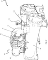
- the illustrated exemplary chiller refrigeration system 10 includes a compressor assembly 30, a condenser 12, and a cooler or evaporator 20 fluidly coupled to form a circuit.
- a first conduit 11 extends from adjacent the outlet 22 of the cooler 20 to the inlet 32 of the compressor assembly 30.
- the outlet 34 of the compressor assembly 30 is coupled by a conduit 13 to an inlet 14 of the condenser 12.
- the condenser 12 includes a first chamber 17, and a second chamber 18 accessible only from the interior of the first chamber 17.
- a float valve 19 within the second chamber 18 is connected to an inlet 24 of the cooler 20 by another conduit 15.
- the compressor assembly 30 may include a rotary, screw, or reciprocating compressor for small systems, or a screw compressor or centrifugal compressor for larger systems.
- a typical compressor assembly 30 includes a housing 36 having a motor 40 at one end and a centrifugal compressor 44 at a second, opposite end, with the two being interconnected by a transmission assembly 42.
- the compressor 44 includes an impeller 46 for accelerating the refrigerant vapor to a high velocity, a diffuser 48 for decelerating the refrigerant to a low velocity while converting kinetic energy to pressure energy, and a discharge plenum (not shown) in the form of a volute or collector to collect the discharge vapor for subsequent flow to a condenser.
- an inlet guide vane assembly 60 Positioned near the inlet 32 of the compressor 30 is an inlet guide vane assembly 60. Because a fluid flowing from the cooler 20 to the compressor 44 must first pass through the inlet guide vane assembly 60 before entering the impeller 46, the inlet guide vane assembly 60 may be used to control the fluid flow into the compressor 44.
- the refrigeration cycle within the chiller refrigeration system 10 may be described as follows.
- the compressor 44 receives a refrigerant vapor from the evaporator/cooler 20 and compresses it to a higher temperature and pressure, with the relatively hot vapor then passing into the first chamber 17 of the condenser 12 where it is cooled and condensed to a liquid state by a heat exchange relationship with a cooling medium, such as water or air for example. Because the second chamber 18 has a lower pressure than the first chamber 17, a portion of the liquid refrigerant flashes to vapor, thereby cooling the remaining liquid. The refrigerant vapor within the second chamber 18 is recondensed by the cool heat exchange medium.
- the refrigerant liquid then drains into the second chamber 18 located between the first chamber 17 and the cooler 20.
- the float valve 19 forms a seal to prevent vapor from the second chamber 18 from entering the cooler 20.
- the refrigerant As the liquid refrigerant passes through the float valve 19, the refrigerant is expanded to a low temperature two phase liquid/vapor state as it passed into the cooler 20.
- the cooler 20 is a heat exchanger which allows heat energy to migrate from a heat exchange medium, such as water for example, to the refrigerant gas. When the gas returns to the compressor 44, the refrigerant is at both the temperature and the pressure at which the refrigeration cycle began.
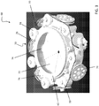
- the inlet guide vane assembly 60 includes a plurality of guide vane subassemblies 70 and a blade ring housing 62.
- Each guide vane subassembly 70 includes a generally flat air foil vane 72, a blade pulley 76 positioned adjacent an exterior of the blade ring housing 62, and a vane shaft 74 connecting the vane 72 to the blade pulley 76.
- the vane shaft 74 rotates within a bearing mounted in the blade ring housing 62.
- the inlet guide vane assembly 60 additionally includes a plurality of idler pulleys 78 mounted to the blade ring housing 62 between adjacent blade pulleys.
- a cable 77 is wound around the plurality of idler pulleys 78 and blade pulleys 76.
- the inlet guide vane assembly 60 is mounted within a suction housing 79.
- the inlet guide vane assembly 60 includes an actuation system 80 for moving the guide vane subassemblies 70 between a closed position and an open position.
- a guide vane actuator 82 is mounted to a portion of the suction housing 79, such as with the illustrated bracket 81 for example.
- An actuator shaft 84 extending from the guide vane actuator 82 includes an actuator sprocket 86.
- One of the blade pulleys 76 acts as a driving pulley and is configured to couple the plurality of blade pulleys 76 to the actuation system 80.
- the vane shaft 74 of the drive pulley extends through a sealing assembly of the suction housing 79 and connects to a drive sprocket 83.
- the sealing assembly 85 prevents leakage of refrigerant to the atmosphere.
- the drive sprocket 83 and the actuator sprocket 86 are connected by a chain 88, such that rotation of the actuator shaft 84 causes the plurality of idler pulleys 78 and blade pulleys 76 to rotate relative to the blade ring housing 62.
- the actuation system 80 may be enclosed within a casing 89 to prevent dust from gathering and to prevent injuries while the compressor 30 is being serviced.
- the described actuation method is for illustrative purposes only, and additional actuation methods for rotating the plurality of inlet guide vane subassemblies 70 are within the scope of this invention.
- a control system 100 including a controller 110, illustrated in FIG. 5 controls the operation of the chiller refrigeration system 10.
- Controller 110 may be implemented using a general-purpose controller executing a computer program to perform the operations described herein. Controller 110 may be implemented using hardware (e.g., ASIC, FPGA) and/or a combination of hardware and software.
- One function of the controller 110 is to control the cooling capacity of the chiller 10, in response to load conditions, such as by adjusting the positioning of the inlet guide vane assembly 60 for example.
- a sensor 120 such as a potentiometer for example, coupled to a portion of the inlet guide vane assembly 60 provides an input signal IGV1 to the controller 110 indicative of the position of the guide vane subassemblies 70.
- the microcontroller 110 is also configured to communicate with the inlet guide vane actuation system 80 such that an output signal from the controller 110 will cause the actuation system 80 to adjust the position of the inlet guide vane subassemblies 70.
- the control system 100 includes an additional plurality of sensors configured to provide an input to the controller 110.
- a first sensor 130 is a pressure transducer configured to provide an input signal PI to the controller 110 indicative of the absolute pressure in the cooler 20.
- a second sensor 135 may be a pressure transducer configured to provide an input signal P2 to the controller 110 indicative of the absolute pressure in the condenser 12.
- the pressure transducers 130, 135 may be located in the conduit 11 extending between the cooler 20 and the compressor inlet 32, and the conduit 13 extending between the compressor outlet 34 and the condenser inlet 14 respectively. The pressure transducers 130, 135 will sense pressures representative of the discharge and suction pressures of the compressor 44.
- the first and second sensors 130, 135 are temperature thermistors.
- the first thermistor 130 will sense the temperature of the refrigerant near the outlet 22 of the cooler 20, and the second thermistor 135 will sense the temperature of the refrigerant near the inlet 14 of the condenser 12.
- one of the first sensor 130 and the second sensor 135 may be a pressure sensor and the other of the first sensor 130 and the second sensor 135 may be a temperature sensor.
- the microcontroller 110 of the control system 100 is also configured to communicate with the drive 90 of the motor 40.
- the drive 90 controls the current drawn by the motor 40, and therefore regulates the speed of the compressor 44.
- the drive is a variable speed drive.
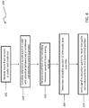
- a method 200 is provided in FIG. 6 for reducing the time required to maximize the capacity of the chiller system 10 at start-up by adjusting the position of the inlet guide vane subassemblies 70 to a partially open position before power is applied to the compressor 44.
- the controller receives the input S1 from the first sensor 130 indicative of the pressure in the cooler 20, and the input S2 from the second sensor 135 indicative of the pressure in the condenser 12.
- the controller 110 uses these collected pressure values, as shown in block 204, to calculate the saturation temperature in both the cooler 20 and the condenser 12 using an algorithm stored in the controller 110.
- the cooler pressure and the condenser pressure should be about the same, and therefore the resultant saturation temperatures should be generally equivalent. However, in instances, where the saturation temperatures differ, the higher, more conservative, temperature will be used to determine an allowable position of the inlet guide vane assembly 60 as described in more detail below.
- the controller 110 will first convert the input S1, S2 from the thermistors into a pressure, and then from that pressure will calculate a corresponding saturation temperature.
- the controller 110 receives an input D1 from the drive 90 indicative of a selected operating speed of the motor 40 during start-up.
- the selected operating speed during start-up may equal the full speed of the motor 40.
- the selected operating speed during start-up may range from about 65% to 100% of full speed depending on the settings of that chiller refrigeration system 10.
- an algorithm for determining the allowable position of the inlet guide vane assembly may be stored within the controller 110 of the control system 100.
- the selected operating speed D1 and the maximum calculated saturation temperature as input into the algorithm to calculate the allowable position of the inlet guide vanes for the system.
- a positioning table that identifies a range of saturation temperatures and inlet guide vanes associated with each saturation temperature may be stored within the controller 110. The table is generated based on an assumed selected operating speed of the compressor 44 during start-up.
- a plurality of vane positioning tables for a range of minimum speeds may be stored within the controller 110.
- the controller 110 includes a vane positioning table for a selected operating speed of about 65% and includes additional tables taken at intervals, such as every 7% for example, until full speed is reached. Based on the selected operating speed D1 input to the controller 110 from the drive 90, the controller 110 will select a corresponding vane positioning table. After selecting the maximum saturation temperature calculated based on the inputs S1, S2 from the condenser 12 and the cooler 20, the controller 110 can identify an allowable position of the inlet guide vane subassemblies 70. In block 210, the controller 110 then sends a signal to the actuation system 80 to move the inlet guide vane subassemblies 70 to the determined allowable position.
- the inlet guide vane subassemblies 70 are in a closed position so that only a minimum flow enters the inlet 32 of the compressor 30.
- the inlet guide vane subassemblies 70 may be partially opened before start-up, thereby allowing a greater initial volumetric flow.
- the time required to move the inlet guide vanes 70 to a fully open position once the compressor 44 is operating is reduced.
- the compressor 44 may more efficiently reach a maximum cooling capacity.
Landscapes
- Engineering & Computer Science (AREA)
- Mechanical Engineering (AREA)
- General Engineering & Computer Science (AREA)
- Physics & Mathematics (AREA)
- Geometry (AREA)
- Thermal Sciences (AREA)
- Control Of Positive-Displacement Air Blowers (AREA)
- Structures Of Non-Positive Displacement Pumps (AREA)
Description
- The invention relates to a method of maximizing the cooling capacity of the chiller refrigeration system at start-up.
- In many conventional chillers, the compressor, such as a centrifugal compressor for example, is driven by a driving means, such as an electric motor for example, either directly or through a transmission. Optimum performance of the compressor is strongly influenced by the rotating speed of the compressor. The volume of refrigerant flowing through the compressor must be adjusted for changes in the load demanded by the air conditioning requirements of the space being cooled. Control of the flow is typically accomplished by varying the inlet guide vanes and the impeller speed, either separately or in a coordinated manner.
- When a conventional chiller system is initially started, the inlet guide vanes are typically in a fully closed position, allowing only a minimum amount of flow into the compressor to prevent the motor from stalling. Only when the motor reaches a full speed will the system begin to open the inlet guide vanes, thereby increasing the capacity of the system. Consequently, a significant amount of time may elapse from when the chiller system is initially started until the guide vanes are fully open and the system is operating at maximum capacity. Some applications, such as data centers for example, require the system to reach a maximum capacity in a shorter amount of time than is allowable using a conventional system.
US 4 381 650 shows a method and control system for operating a vapor compression refrigeration system to prevent oil pump cavitation during startup of the refrigeration system is disclosed. The control system includes a temperature or pressure sensor located in the evaporator of the refrigeration system, a microprocessor, and an inlet guide vane control mechanism. During startup, the pressure of the gaseous refrigerant or the temperature of the liquid refrigerant in the evaporator of the refrigeration system, or compressor suction line pressure, is measured and an electrical signal corresponding to the measured pressure or temperature is processed by the microprocessor to determine the actual rate of pulldown of refrigerant pressure in the evaporator. The microprocessor compares the actual pulldown rate to a pull down rate which has been predetermined to prevent compressor oil pump cavitation. The microprocessor controls the opening and closing of the inlet guide vanes to the compressor to adjust the flow of refrigerant to the compressor to achieve a pulldown rate which is approximately equal to the predetermined rate which prevents oil pump cavitation. - According to an aspect of the invention, a method of positioning an inlet guide vane assembly before start-up of a chiller system including a compressor, a condenser, and a cooler is provided including receiving a first input from sensors located in the cooler and the condenser. A saturation temperature is calculated based on the input from the sensors. A second input indicative of a minimum speed of a motor coupled to the compressor at start-up is received. Using the calculated saturation temperature and the second input, an allowable position of the inlet guide vane assembly is determined. The inlet guide vane assembly is then moved to the determined allowable position.
- These and other advantages and features will become more apparent from the following description taken in conjunction with the drawings.
- The subject matter, which is regarded as the invention, is particularly pointed out and distinctly claimed in the claims at the conclusion of the specification. The foregoing and other features, and advantages of the invention are apparent from the following detailed description taken in conjunction with the accompanying drawings in which:
-
FIG. 1 is a schematic illustration of an exemplary chiller refrigeration system; -
FIG. 2 is a perspective view of an exemplary chiller refrigeration system; -
FIG.3 is a perspective view of an exemplary inlet guide vane assembly; -
FIG. 4 is a perspective view of an exemplary inlet guide vane actuation system; -
FIG. 5 is a control system for a chiller refrigeration system in accordance with an embodiment of the invention; and -
FIG. 6 is a method for determining an allowable position of the inlet guide vane assembly before start-up of the chiller refrigeration system in accordance with an embodiment of the invention. - Referring now to
FIGS. 1 and2 , the illustrated exemplarychiller refrigeration system 10 includes acompressor assembly 30, acondenser 12, and a cooler orevaporator 20 fluidly coupled to form a circuit. Afirst conduit 11 extends from adjacent theoutlet 22 of thecooler 20 to theinlet 32 of thecompressor assembly 30. Theoutlet 34 of thecompressor assembly 30 is coupled by aconduit 13 to aninlet 14 of thecondenser 12. In one embodiment, thecondenser 12 includes afirst chamber 17, and asecond chamber 18 accessible only from the interior of thefirst chamber 17. Afloat valve 19 within thesecond chamber 18 is connected to aninlet 24 of thecooler 20 by anotherconduit 15. Depending on the size of thechiller system 10, thecompressor assembly 30 may include a rotary, screw, or reciprocating compressor for small systems, or a screw compressor or centrifugal compressor for larger systems. Atypical compressor assembly 30 includes ahousing 36 having amotor 40 at one end and acentrifugal compressor 44 at a second, opposite end, with the two being interconnected by atransmission assembly 42. Thecompressor 44 includes animpeller 46 for accelerating the refrigerant vapor to a high velocity, adiffuser 48 for decelerating the refrigerant to a low velocity while converting kinetic energy to pressure energy, and a discharge plenum (not shown) in the form of a volute or collector to collect the discharge vapor for subsequent flow to a condenser. Positioned near theinlet 32 of thecompressor 30 is an inletguide vane assembly 60. Because a fluid flowing from thecooler 20 to thecompressor 44 must first pass through the inletguide vane assembly 60 before entering theimpeller 46, the inletguide vane assembly 60 may be used to control the fluid flow into thecompressor 44. - The refrigeration cycle within the
chiller refrigeration system 10 may be described as follows. Thecompressor 44 receives a refrigerant vapor from the evaporator/cooler 20 and compresses it to a higher temperature and pressure, with the relatively hot vapor then passing into thefirst chamber 17 of thecondenser 12 where it is cooled and condensed to a liquid state by a heat exchange relationship with a cooling medium, such as water or air for example. Because thesecond chamber 18 has a lower pressure than thefirst chamber 17, a portion of the liquid refrigerant flashes to vapor, thereby cooling the remaining liquid. The refrigerant vapor within thesecond chamber 18 is recondensed by the cool heat exchange medium. The refrigerant liquid then drains into thesecond chamber 18 located between thefirst chamber 17 and thecooler 20. Thefloat valve 19 forms a seal to prevent vapor from thesecond chamber 18 from entering thecooler 20. As the liquid refrigerant passes through thefloat valve 19, the refrigerant is expanded to a low temperature two phase liquid/vapor state as it passed into thecooler 20. Thecooler 20 is a heat exchanger which allows heat energy to migrate from a heat exchange medium, such as water for example, to the refrigerant gas. When the gas returns to thecompressor 44, the refrigerant is at both the temperature and the pressure at which the refrigeration cycle began. - Referring now to
FIGS. 3 and4 , an exemplary inletguide vane assembly 60 is illustrated in more detail. The inletguide vane assembly 60 includes a plurality ofguide vane subassemblies 70 and ablade ring housing 62. Eachguide vane subassembly 70 includes a generally flatair foil vane 72, ablade pulley 76 positioned adjacent an exterior of theblade ring housing 62, and avane shaft 74 connecting thevane 72 to theblade pulley 76. Thevane shaft 74 rotates within a bearing mounted in theblade ring housing 62. The inletguide vane assembly 60 additionally includes a plurality ofidler pulleys 78 mounted to theblade ring housing 62 between adjacent blade pulleys. Acable 77 is wound around the plurality ofidler pulleys 78 andblade pulleys 76. The inletguide vane assembly 60 is mounted within asuction housing 79. - The inlet
guide vane assembly 60 includes anactuation system 80 for moving theguide vane subassemblies 70 between a closed position and an open position. Aguide vane actuator 82 is mounted to a portion of thesuction housing 79, such as with the illustratedbracket 81 for example. Anactuator shaft 84 extending from theguide vane actuator 82 includes an actuator sprocket 86. One of theblade pulleys 76 acts as a driving pulley and is configured to couple the plurality ofblade pulleys 76 to theactuation system 80. Thevane shaft 74 of the drive pulley extends through a sealing assembly of thesuction housing 79 and connects to adrive sprocket 83. Thesealing assembly 85 prevents leakage of refrigerant to the atmosphere. Thedrive sprocket 83 and the actuator sprocket 86 are connected by achain 88, such that rotation of theactuator shaft 84 causes the plurality ofidler pulleys 78 andblade pulleys 76 to rotate relative to theblade ring housing 62. Theactuation system 80 may be enclosed within a casing 89 to prevent dust from gathering and to prevent injuries while thecompressor 30 is being serviced. The described actuation method is for illustrative purposes only, and additional actuation methods for rotating the plurality of inletguide vane subassemblies 70 are within the scope of this invention. - A
control system 100 including acontroller 110, illustrated inFIG. 5 , controls the operation of thechiller refrigeration system 10.Controller 110 may be implemented using a general-purpose controller executing a computer program to perform the operations described herein.Controller 110 may be implemented using hardware (e.g., ASIC, FPGA) and/or a combination of hardware and software. One function of thecontroller 110 is to control the cooling capacity of thechiller 10, in response to load conditions, such as by adjusting the positioning of the inletguide vane assembly 60 for example. Asensor 120, such as a potentiometer for example, coupled to a portion of the inletguide vane assembly 60 provides an input signal IGV1 to thecontroller 110 indicative of the position of theguide vane subassemblies 70. Themicrocontroller 110 is also configured to communicate with the inlet guidevane actuation system 80 such that an output signal from thecontroller 110 will cause theactuation system 80 to adjust the position of the inletguide vane subassemblies 70. - The
control system 100 includes an additional plurality of sensors configured to provide an input to thecontroller 110. In one embodiment, afirst sensor 130 is a pressure transducer configured to provide an input signal PI to thecontroller 110 indicative of the absolute pressure in the cooler 20. Asecond sensor 135 may be a pressure transducer configured to provide an input signal P2 to thecontroller 110 indicative of the absolute pressure in thecondenser 12. The pressure transducers 130, 135 may be located in theconduit 11 extending between the cooler 20 and thecompressor inlet 32, and theconduit 13 extending between thecompressor outlet 34 and thecondenser inlet 14 respectively. The pressure transducers 130, 135 will sense pressures representative of the discharge and suction pressures of thecompressor 44. In another embodiment, the first andsecond sensors first thermistor 130 will sense the temperature of the refrigerant near theoutlet 22 of the cooler 20, and thesecond thermistor 135 will sense the temperature of the refrigerant near theinlet 14 of thecondenser 12. Alternatively, one of thefirst sensor 130 and thesecond sensor 135 may be a pressure sensor and the other of thefirst sensor 130 and thesecond sensor 135 may be a temperature sensor. Themicrocontroller 110 of thecontrol system 100 is also configured to communicate with thedrive 90 of themotor 40. Thedrive 90 controls the current drawn by themotor 40, and therefore regulates the speed of thecompressor 44. In one embodiment, the drive is a variable speed drive. - A
method 200 is provided inFIG. 6 for reducing the time required to maximize the capacity of thechiller system 10 at start-up by adjusting the position of the inletguide vane subassemblies 70 to a partially open position before power is applied to thecompressor 44. As shown inblock 202, when the motor is in an idle, non-rotating state, the controller receives the input S1 from thefirst sensor 130 indicative of the pressure in the cooler 20, and the input S2 from thesecond sensor 135 indicative of the pressure in thecondenser 12. Thecontroller 110 then uses these collected pressure values, as shown inblock 204, to calculate the saturation temperature in both the cooler 20 and thecondenser 12 using an algorithm stored in thecontroller 110. Because thechiller refrigeration system 10 is not running, the cooler pressure and the condenser pressure should be about the same, and therefore the resultant saturation temperatures should be generally equivalent. However, in instances, where the saturation temperatures differ, the higher, more conservative, temperature will be used to determine an allowable position of the inletguide vane assembly 60 as described in more detail below. In embodiments where thesensors controller 110 will first convert the input S1, S2 from the thermistors into a pressure, and then from that pressure will calculate a corresponding saturation temperature. - In
block 206, thecontroller 110 receives an input D1 from thedrive 90 indicative of a selected operating speed of themotor 40 during start-up. In systems having a non-variable frequency drive, the selected operating speed during start-up may equal the full speed of themotor 40. Insystems 10 having a variable frequency drive, the selected operating speed during start-up may range from about 65% to 100% of full speed depending on the settings of thatchiller refrigeration system 10. - As shown in
block 208, an algorithm for determining the allowable position of the inlet guide vane assembly may be stored within thecontroller 110 of thecontrol system 100. The selected operating speed D1 and the maximum calculated saturation temperature as input into the algorithm to calculate the allowable position of the inlet guide vanes for the system. Alternatively, a positioning table that identifies a range of saturation temperatures and inlet guide vanes associated with each saturation temperature may be stored within thecontroller 110. The table is generated based on an assumed selected operating speed of thecompressor 44 during start-up. A plurality of vane positioning tables for a range of minimum speeds may be stored within thecontroller 110. In one embodiment, thecontroller 110 includes a vane positioning table for a selected operating speed of about 65% and includes additional tables taken at intervals, such as every 7% for example, until full speed is reached. Based on the selected operating speed D1 input to thecontroller 110 from thedrive 90, thecontroller 110 will select a corresponding vane positioning table. After selecting the maximum saturation temperature calculated based on the inputs S1, S2 from thecondenser 12 and the cooler 20, thecontroller 110 can identify an allowable position of the inletguide vane subassemblies 70. Inblock 210, thecontroller 110 then sends a signal to theactuation system 80 to move the inletguide vane subassemblies 70 to the determined allowable position. - During a conventional start-up of a
chiller refrigeration system 100, the inletguide vane subassemblies 70 are in a closed position so that only a minimum flow enters theinlet 32 of thecompressor 30. However, because the sensed pressures or temperatures S1, S2 in the cooler 20 andcondenser 12 are less than the worst-case scenario assumed during design of thecompressor 44, the inletguide vane subassemblies 70 may be partially opened before start-up, thereby allowing a greater initial volumetric flow. By partially opening theguide vanes 70, the time required to move theinlet guide vanes 70 to a fully open position once thecompressor 44 is operating is reduced. In addition, because theinlet guide vanes 70 have a shorter distance to move to reach a fully open position, thecompressor 44 may more efficiently reach a maximum cooling capacity. - While the invention has been described in detail in connection with only a limited number of embodiments, it should be readily understood that the invention is not limited to such disclosed embodiments. Rather, the invention can be modified to incorporate any number of variations, alterations, substitutions or equivalent arrangements not heretofore described, but which are commensurate with the scope of the invention. Additionally, while various embodiments of the invention have been described, it is to be understood that aspects of the invention may include only some of the described embodiments. Accordingly, the invention is not to be seen as limited by the foregoing description, but is only limited by the scope of the appended claims.
Claims (15)
- A method of positioning an inlet guide vane assembly (60) before start-up of a chiller system (10) including a compressor (30) having a motor (40), a condenser (12), and a cooler (20), characterized in that the method comprises:receiving a first input from sensors located in the cooler (20) and the condenser (12) when the motor (40) is in an idle, non-rotating state;calculating a saturation temperature in the cooler (20) and a saturation temperature in the condenser (12) based on the input from the sensors;receiving a second input indicative of a minimum speed of a motor (40) coupled to the compressor (30) at start-up;determining an allowable position of the inlet guide vane assembly (60) based on the higher one of the calculated saturation temperatures and the second input; andmoving the inlet guide vane assembly (60) to the determined allowable position.
- The method according to claim 1, wherein the chiller system (10) includes a control system (100) having a controller (110).
- The method according to claim 1, wherein the first input from the sensors is provided to a controller (110).
- The method according to claim 1, wherein the sensors located in the cooler (20) and condenser (12) are pressure sensors; or
wherein an algorithm for determining an allowable position of the inlet guide vane assembly (60) based on the calculated saturation temperature and the second input is stored in the controller (110). - The method according to claim 1, wherein the sensors located in the cooler (20) and condenser (12) are temperature sensors.
- The method according to claim 5, further comprising converting the first input from the temperature sensors into a pressure to calculate the saturation temperature.
- The method according to claim 2, wherein an algorithm for converting a pressure into a saturation temperature is stored within the controller (110).
- The method according to claim 1, wherein a saturation temperature is determined for both the cooler (20) and the condenser (12) based on the first input.
- The method according to claim 8, wherein the saturation temperature of the cooler (20) is compared to the saturation temperature of the condenser (12) and whichever is greater is used to determine an allowable position of the inlet guide vane assembly.
- The method according to claim 2, wherein a drive (90) coupled to the motor (40) provides the second input to the controller.
- The method according to claim 10, wherein if the drive (90) is a non-variable frequency drive, the minimum speed of the motor (40) at start up is full speed; or
wherein if the drive (90) is a variable-frequency drive, the minimum speed of the motor (40) may be in the range of between about 65% and 100% of a full speed of the motor (40). - The method according to claim 1, wherein at least one vane positioning table is stored in the controller (110), the vane positioning table having a range of saturation temperatures and a corresponding allowable position of the inlet guide vane assembly (60) for each saturation temperature.
- The method according to claim 12, wherein the vane positioning table is created based on an assumed minimum speed of the motor (40).
- The method according to claim 13, wherein a controller (110) has a plurality of vane positioning tables stored, the plurality of tables being configured for a range of minimum speeds of the motor (40) at start-up.
- The method according to claim 2, wherein the controller (110) provides a signal to an actuation system (80) coupled to the inlet guide vane assembly (60).
Applications Claiming Priority (2)
| Application Number | Priority Date | Filing Date | Title |
|---|---|---|---|
| US201261711278P | 2012-10-09 | 2012-10-09 | |
| PCT/US2013/054272 WO2014058524A1 (en) | 2012-10-09 | 2013-08-09 | Centrifugal compressor inlet guide vane control |
Publications (2)
| Publication Number | Publication Date |
|---|---|
| EP2906885A1 EP2906885A1 (en) | 2015-08-19 |
| EP2906885B1 true EP2906885B1 (en) | 2019-10-02 |
Family
ID=49001092
Family Applications (1)
| Application Number | Title | Priority Date | Filing Date |
|---|---|---|---|
| EP13750815.6A Active EP2906885B1 (en) | 2012-10-09 | 2013-08-09 | Centrifugal compressor inlet guide vane control |
Country Status (5)
| Country | Link |
|---|---|
| US (1) | US9677566B2 (en) |
| EP (1) | EP2906885B1 (en) |
| CN (1) | CN104736952B (en) |
| ES (1) | ES2763334T3 (en) |
| WO (1) | WO2014058524A1 (en) |
Families Citing this family (6)
| Publication number | Priority date | Publication date | Assignee | Title |
|---|---|---|---|---|
| EP2959236B1 (en) * | 2013-02-20 | 2018-10-31 | Carrier Corporation | Inlet guide vane mechanism |
| ITUB20160324A1 (en) | 2016-01-25 | 2017-07-25 | Nuovo Pignone Tecnologie Srl | COMPRESSOR TRAIN START UP WITH VARIABLE ENTRY GUIDE ROOMS |
| DE102017115623A1 (en) | 2016-07-13 | 2018-01-18 | Trane International Inc. | Variable economizer injection position |
| CN107388646A (en) * | 2017-08-10 | 2017-11-24 | 珠海格力电器股份有限公司 | Refrigerant flow regulating mechanism and refrigerating device |
| US12044245B2 (en) | 2021-04-29 | 2024-07-23 | Copeland Lp | Mass flow interpolation systems and methods for dynamic compressors |
| CN115493318A (en) | 2021-06-17 | 2022-12-20 | 开利公司 | Centrifugal compressor control method and air conditioning system |
Family Cites Families (31)
| Publication number | Priority date | Publication date | Assignee | Title |
|---|---|---|---|---|
| US2817213A (en) * | 1955-10-17 | 1957-12-24 | Trane Co | Refrigeration apparatus with load limit control |
| US3973391A (en) | 1974-08-08 | 1976-08-10 | Westinghouse Electric Corporation | Control apparatus for modulating the inlet guide vanes of a gas turbine employed in a combined cycle electric power generating plant as a function of load or inlet blade path temperature |
| US4227862A (en) * | 1978-09-19 | 1980-10-14 | Frick Company | Solid state compressor control system |
| US4270361A (en) * | 1979-03-14 | 1981-06-02 | Barge Michael A | Energy management controller for centrifugal water chiller |
| US4399663A (en) * | 1981-11-27 | 1983-08-23 | Carrier Corporation | Mechanical control system for preventing compressor lubrication pump cavitation in a refrigeration system |
| US4381650A (en) * | 1981-11-27 | 1983-05-03 | Carrier Corporation | Electronic control system for regulating startup operation of a compressor in a refrigeration system |
| US4589060A (en) * | 1984-05-14 | 1986-05-13 | Carrier Corporation | Microcomputer system for controlling the capacity of a refrigeration system |
| US4514989A (en) * | 1984-05-14 | 1985-05-07 | Carrier Corporation | Method and control system for protecting an electric motor driven compressor in a refrigeration system |
| US4538422A (en) * | 1984-05-14 | 1985-09-03 | Carrier Corporation | Method and control system for limiting compressor capacity in a refrigeration system upon a recycle start |
| US4535598A (en) * | 1984-05-14 | 1985-08-20 | Carrier Corporation | Method and control system for verifying sensor operation in a refrigeration system |
| US4535607A (en) * | 1984-05-14 | 1985-08-20 | Carrier Corporation | Method and control system for limiting the load placed on a refrigeration system upon a recycle start |
| US4546618A (en) * | 1984-09-20 | 1985-10-15 | Borg-Warner Corporation | Capacity control systems for inverter-driven centrifugal compressor based water chillers |
| US4608833A (en) | 1984-12-24 | 1986-09-02 | Borg-Warner Corporation | Self-optimizing, capacity control system for inverter-driven centrifugal compressor based water chillers |
| US4611969A (en) * | 1985-08-19 | 1986-09-16 | Carrier Corporation | Calibrating apparatus and method for a movable diffuser wall in a centrifugal compressor |
| US4686834A (en) * | 1986-06-09 | 1987-08-18 | American Standard Inc. | Centrifugal compressor controller for minimizing power consumption while avoiding surge |
| US4989403A (en) | 1988-05-23 | 1991-02-05 | Sundstrand Corporation | Surge protected gas turbine engine for providing variable bleed air flow |
| US5537830A (en) | 1994-11-28 | 1996-07-23 | American Standard Inc. | Control method and appartus for a centrifugal chiller using a variable speed impeller motor drive |
| US5746062A (en) | 1996-04-11 | 1998-05-05 | York International Corporation | Methods and apparatuses for detecting surge in centrifugal compressors |
| US5669225A (en) | 1996-06-27 | 1997-09-23 | York International Corporation | Variable speed control of a centrifugal chiller using fuzzy logic |
| US6341238B1 (en) | 1998-10-01 | 2002-01-22 | United Technologies Corporation | Robust engine variable vane monitor logic |
| US6463748B1 (en) | 1999-12-06 | 2002-10-15 | Mainstream Engineering Corporation | Apparatus and method for controlling a magnetic bearing centrifugal chiller |
| JP4013752B2 (en) | 2002-12-11 | 2007-11-28 | 株式会社日立プラントテクノロジー | Centrifugal compressor |
| US7328587B2 (en) | 2004-01-23 | 2008-02-12 | York International Corporation | Integrated adaptive capacity control for a steam turbine powered chiller unit |
| US7972105B2 (en) | 2007-05-10 | 2011-07-05 | General Electric Company | Turbine anti-rotating stall schedule |
| TWI437167B (en) | 2007-10-31 | 2014-05-11 | Johnson Controls Tech Co | Control system |
| CA2737516A1 (en) | 2008-09-18 | 2010-03-25 | Siemens Aktiengesellschaft | Method, system, device for variable guide vanes |
| GB0915616D0 (en) | 2009-09-08 | 2009-10-07 | Rolls Royce Plc | Surge margin regulation |
| US10544801B2 (en) | 2009-10-21 | 2020-01-28 | Carrier Corporation | Centrifugal compressor part load control algorithm for improved performance |
| CN102713304B (en) | 2009-11-03 | 2015-01-28 | 英格索尔-兰德公司 | Compressor inlet guide vanes |
| JP5308319B2 (en) | 2009-12-02 | 2013-10-09 | 三菱重工業株式会社 | Centrifugal compressor impeller |
| US20110176913A1 (en) * | 2010-01-19 | 2011-07-21 | Stephen Paul Wassynger | Non-linear asymmetric variable guide vane schedule |
-
2013
- 2013-08-09 US US14/433,316 patent/US9677566B2/en active Active
- 2013-08-09 ES ES13750815T patent/ES2763334T3/en active Active
- 2013-08-09 EP EP13750815.6A patent/EP2906885B1/en active Active
- 2013-08-09 CN CN201380052816.2A patent/CN104736952B/en active Active
- 2013-08-09 WO PCT/US2013/054272 patent/WO2014058524A1/en not_active Ceased
Non-Patent Citations (1)
| Title |
|---|
| None * |
Also Published As
| Publication number | Publication date |
|---|---|
| CN104736952A (en) | 2015-06-24 |
| CN104736952B (en) | 2016-09-14 |
| US9677566B2 (en) | 2017-06-13 |
| ES2763334T3 (en) | 2020-05-28 |
| WO2014058524A1 (en) | 2014-04-17 |
| US20150275908A1 (en) | 2015-10-01 |
| EP2906885A1 (en) | 2015-08-19 |
Similar Documents
| Publication | Publication Date | Title |
|---|---|---|
| EP2906885B1 (en) | Centrifugal compressor inlet guide vane control | |
| CN102741623B (en) | Turbo refrigerating machine and heat source system and control method therefor | |
| US8567207B2 (en) | Compressor control system using a variable geometry diffuser | |
| KR930012234B1 (en) | Capacity Control Air Conditioner | |
| EP2959236B1 (en) | Inlet guide vane mechanism | |
| CN107735575B (en) | Capacity control system and method for multistage centrifugal compressors | |
| CN103635697B (en) | Compressor Surge Detection | |
| US20160327049A1 (en) | Multi-stage compression system and method of operating the same | |
| JP6454564B2 (en) | Turbo refrigerator | |
| EP2705255B1 (en) | Surge prevention during startup of a chiller compressor | |
| US20090277197A1 (en) | Evaporator apparatus and method for modulating cooling | |
| JP5306478B2 (en) | Heat pump device, two-stage compressor, and operation method of heat pump device | |
| KR20120010252A (en) | Controls for Driving Condenser Fans | |
| EP3356681B1 (en) | Centrifugal compressor with flow regulation and surge prevention by axially shifting the impeller | |
| JP5981180B2 (en) | Turbo refrigerator and control method thereof | |
| EP1926914A2 (en) | Multi-stage compression system including variable speed motors | |
| RU2016149100A (en) | DYNAMICALLY CONTROLLED VAPOR COMPRESSION COOLING SYSTEM WITH A CENTRIFUGAL COMPRESSOR | |
| JP2011241760A (en) | Motor-driven compressor, heat source machine, and method of controlling the heat source machine | |
| CN117404310B (en) | Air suspension centrifugal compressor, axial force balancing system, control method and control device | |
| KR20200063472A (en) | An Apparatus for Controlling an Operation of a Refrigerating Vehicle Based on Detecting a Temperature and a Pressure and the Method for the Same | |
| HK1256003A1 (en) | Centrifugal compressor with flow regulation and surge prevention by axially shifting the impeller | |
| HK1256003B (en) | Centrifugal compressor with flow regulation and surge prevention by axially shifting the impeller |
Legal Events
| Date | Code | Title | Description |
|---|---|---|---|
| PUAI | Public reference made under article 153(3) epc to a published international application that has entered the european phase |
Free format text: ORIGINAL CODE: 0009012 |
|
| 17P | Request for examination filed |
Effective date: 20150416 |
|
| AK | Designated contracting states |
Kind code of ref document: A1 Designated state(s): AL AT BE BG CH CY CZ DE DK EE ES FI FR GB GR HR HU IE IS IT LI LT LU LV MC MK MT NL NO PL PT RO RS SE SI SK SM TR |
|
| AX | Request for extension of the european patent |
Extension state: BA ME |
|
| DAX | Request for extension of the european patent (deleted) | ||
| GRAP | Despatch of communication of intention to grant a patent |
Free format text: ORIGINAL CODE: EPIDOSNIGR1 |
|
| STAA | Information on the status of an ep patent application or granted ep patent |
Free format text: STATUS: GRANT OF PATENT IS INTENDED |
|
| INTG | Intention to grant announced |
Effective date: 20190308 |
|
| GRAS | Grant fee paid |
Free format text: ORIGINAL CODE: EPIDOSNIGR3 |
|
| GRAA | (expected) grant |
Free format text: ORIGINAL CODE: 0009210 |
|
| STAA | Information on the status of an ep patent application or granted ep patent |
Free format text: STATUS: THE PATENT HAS BEEN GRANTED |
|
| AK | Designated contracting states |
Kind code of ref document: B1 Designated state(s): AL AT BE BG CH CY CZ DE DK EE ES FI FR GB GR HR HU IE IS IT LI LT LU LV MC MK MT NL NO PL PT RO RS SE SI SK SM TR |
|
| REG | Reference to a national code |
Ref country code: GB Ref legal event code: FG4D |
|
| REG | Reference to a national code |
Ref country code: CH Ref legal event code: EP Ref country code: AT Ref legal event code: REF Ref document number: 1186634 Country of ref document: AT Kind code of ref document: T Effective date: 20191015 |
|
| REG | Reference to a national code |
Ref country code: DE Ref legal event code: R096 Ref document number: 602013061235 Country of ref document: DE |
|
| REG | Reference to a national code |
Ref country code: IE Ref legal event code: FG4D |
|
| REG | Reference to a national code |
Ref country code: CH Ref legal event code: NV Representative=s name: BOHEST AG, CH |
|
| REG | Reference to a national code |
Ref country code: NL Ref legal event code: MP Effective date: 20191002 |
|
| REG | Reference to a national code |
Ref country code: LT Ref legal event code: MG4D |
|
| REG | Reference to a national code |
Ref country code: AT Ref legal event code: MK05 Ref document number: 1186634 Country of ref document: AT Kind code of ref document: T Effective date: 20191002 |
|
| PG25 | Lapsed in a contracting state [announced via postgrant information from national office to epo] |
Ref country code: GR Free format text: LAPSE BECAUSE OF FAILURE TO SUBMIT A TRANSLATION OF THE DESCRIPTION OR TO PAY THE FEE WITHIN THE PRESCRIBED TIME-LIMIT Effective date: 20200103 Ref country code: NO Free format text: LAPSE BECAUSE OF FAILURE TO SUBMIT A TRANSLATION OF THE DESCRIPTION OR TO PAY THE FEE WITHIN THE PRESCRIBED TIME-LIMIT Effective date: 20200102 Ref country code: BG Free format text: LAPSE BECAUSE OF FAILURE TO SUBMIT A TRANSLATION OF THE DESCRIPTION OR TO PAY THE FEE WITHIN THE PRESCRIBED TIME-LIMIT Effective date: 20200102 Ref country code: LT Free format text: LAPSE BECAUSE OF FAILURE TO SUBMIT A TRANSLATION OF THE DESCRIPTION OR TO PAY THE FEE WITHIN THE PRESCRIBED TIME-LIMIT Effective date: 20191002 Ref country code: PL Free format text: LAPSE BECAUSE OF FAILURE TO SUBMIT A TRANSLATION OF THE DESCRIPTION OR TO PAY THE FEE WITHIN THE PRESCRIBED TIME-LIMIT Effective date: 20191002 Ref country code: AT Free format text: LAPSE BECAUSE OF FAILURE TO SUBMIT A TRANSLATION OF THE DESCRIPTION OR TO PAY THE FEE WITHIN THE PRESCRIBED TIME-LIMIT Effective date: 20191002 Ref country code: NL Free format text: LAPSE BECAUSE OF FAILURE TO SUBMIT A TRANSLATION OF THE DESCRIPTION OR TO PAY THE FEE WITHIN THE PRESCRIBED TIME-LIMIT Effective date: 20191002 Ref country code: SE Free format text: LAPSE BECAUSE OF FAILURE TO SUBMIT A TRANSLATION OF THE DESCRIPTION OR TO PAY THE FEE WITHIN THE PRESCRIBED TIME-LIMIT Effective date: 20191002 Ref country code: LV Free format text: LAPSE BECAUSE OF FAILURE TO SUBMIT A TRANSLATION OF THE DESCRIPTION OR TO PAY THE FEE WITHIN THE PRESCRIBED TIME-LIMIT Effective date: 20191002 Ref country code: PT Free format text: LAPSE BECAUSE OF FAILURE TO SUBMIT A TRANSLATION OF THE DESCRIPTION OR TO PAY THE FEE WITHIN THE PRESCRIBED TIME-LIMIT Effective date: 20200203 Ref country code: FI Free format text: LAPSE BECAUSE OF FAILURE TO SUBMIT A TRANSLATION OF THE DESCRIPTION OR TO PAY THE FEE WITHIN THE PRESCRIBED TIME-LIMIT Effective date: 20191002 |
|
| REG | Reference to a national code |
Ref country code: ES Ref legal event code: FG2A Ref document number: 2763334 Country of ref document: ES Kind code of ref document: T3 Effective date: 20200528 |
|
| PG25 | Lapsed in a contracting state [announced via postgrant information from national office to epo] |
Ref country code: IS Free format text: LAPSE BECAUSE OF FAILURE TO SUBMIT A TRANSLATION OF THE DESCRIPTION OR TO PAY THE FEE WITHIN THE PRESCRIBED TIME-LIMIT Effective date: 20200224 Ref country code: RS Free format text: LAPSE BECAUSE OF FAILURE TO SUBMIT A TRANSLATION OF THE DESCRIPTION OR TO PAY THE FEE WITHIN THE PRESCRIBED TIME-LIMIT Effective date: 20191002 Ref country code: HR Free format text: LAPSE BECAUSE OF FAILURE TO SUBMIT A TRANSLATION OF THE DESCRIPTION OR TO PAY THE FEE WITHIN THE PRESCRIBED TIME-LIMIT Effective date: 20191002 Ref country code: CZ Free format text: LAPSE BECAUSE OF FAILURE TO SUBMIT A TRANSLATION OF THE DESCRIPTION OR TO PAY THE FEE WITHIN THE PRESCRIBED TIME-LIMIT Effective date: 20191002 |
|
| PG25 | Lapsed in a contracting state [announced via postgrant information from national office to epo] |
Ref country code: AL Free format text: LAPSE BECAUSE OF FAILURE TO SUBMIT A TRANSLATION OF THE DESCRIPTION OR TO PAY THE FEE WITHIN THE PRESCRIBED TIME-LIMIT Effective date: 20191002 |
|
| REG | Reference to a national code |
Ref country code: DE Ref legal event code: R097 Ref document number: 602013061235 Country of ref document: DE |
|
| PG2D | Information on lapse in contracting state deleted |
Ref country code: IS |
|
| PG25 | Lapsed in a contracting state [announced via postgrant information from national office to epo] |
Ref country code: DK Free format text: LAPSE BECAUSE OF FAILURE TO SUBMIT A TRANSLATION OF THE DESCRIPTION OR TO PAY THE FEE WITHIN THE PRESCRIBED TIME-LIMIT Effective date: 20191002 Ref country code: RO Free format text: LAPSE BECAUSE OF FAILURE TO SUBMIT A TRANSLATION OF THE DESCRIPTION OR TO PAY THE FEE WITHIN THE PRESCRIBED TIME-LIMIT Effective date: 20191002 Ref country code: EE Free format text: LAPSE BECAUSE OF FAILURE TO SUBMIT A TRANSLATION OF THE DESCRIPTION OR TO PAY THE FEE WITHIN THE PRESCRIBED TIME-LIMIT Effective date: 20191002 Ref country code: IS Free format text: LAPSE BECAUSE OF FAILURE TO SUBMIT A TRANSLATION OF THE DESCRIPTION OR TO PAY THE FEE WITHIN THE PRESCRIBED TIME-LIMIT Effective date: 20200202 |
|
| PLBE | No opposition filed within time limit |
Free format text: ORIGINAL CODE: 0009261 |
|
| STAA | Information on the status of an ep patent application or granted ep patent |
Free format text: STATUS: NO OPPOSITION FILED WITHIN TIME LIMIT |
|
| PG25 | Lapsed in a contracting state [announced via postgrant information from national office to epo] |
Ref country code: SK Free format text: LAPSE BECAUSE OF FAILURE TO SUBMIT A TRANSLATION OF THE DESCRIPTION OR TO PAY THE FEE WITHIN THE PRESCRIBED TIME-LIMIT Effective date: 20191002 Ref country code: SM Free format text: LAPSE BECAUSE OF FAILURE TO SUBMIT A TRANSLATION OF THE DESCRIPTION OR TO PAY THE FEE WITHIN THE PRESCRIBED TIME-LIMIT Effective date: 20191002 Ref country code: IT Free format text: LAPSE BECAUSE OF FAILURE TO SUBMIT A TRANSLATION OF THE DESCRIPTION OR TO PAY THE FEE WITHIN THE PRESCRIBED TIME-LIMIT Effective date: 20191002 |
|
| 26N | No opposition filed |
Effective date: 20200703 |
|
| PG25 | Lapsed in a contracting state [announced via postgrant information from national office to epo] |
Ref country code: SI Free format text: LAPSE BECAUSE OF FAILURE TO SUBMIT A TRANSLATION OF THE DESCRIPTION OR TO PAY THE FEE WITHIN THE PRESCRIBED TIME-LIMIT Effective date: 20191002 |
|
| PG25 | Lapsed in a contracting state [announced via postgrant information from national office to epo] |
Ref country code: MC Free format text: LAPSE BECAUSE OF FAILURE TO SUBMIT A TRANSLATION OF THE DESCRIPTION OR TO PAY THE FEE WITHIN THE PRESCRIBED TIME-LIMIT Effective date: 20191002 |
|
| GBPC | Gb: european patent ceased through non-payment of renewal fee |
Effective date: 20200809 |
|
| PG25 | Lapsed in a contracting state [announced via postgrant information from national office to epo] |
Ref country code: LU Free format text: LAPSE BECAUSE OF NON-PAYMENT OF DUE FEES Effective date: 20200809 |
|
| REG | Reference to a national code |
Ref country code: BE Ref legal event code: MM Effective date: 20200831 |
|
| PG25 | Lapsed in a contracting state [announced via postgrant information from national office to epo] |
Ref country code: IE Free format text: LAPSE BECAUSE OF NON-PAYMENT OF DUE FEES Effective date: 20200809 Ref country code: GB Free format text: LAPSE BECAUSE OF NON-PAYMENT OF DUE FEES Effective date: 20200809 Ref country code: BE Free format text: LAPSE BECAUSE OF NON-PAYMENT OF DUE FEES Effective date: 20200831 |
|
| PGFP | Annual fee paid to national office [announced via postgrant information from national office to epo] |
Ref country code: CH Payment date: 20210722 Year of fee payment: 9 |
|
| PG25 | Lapsed in a contracting state [announced via postgrant information from national office to epo] |
Ref country code: TR Free format text: LAPSE BECAUSE OF FAILURE TO SUBMIT A TRANSLATION OF THE DESCRIPTION OR TO PAY THE FEE WITHIN THE PRESCRIBED TIME-LIMIT Effective date: 20191002 Ref country code: MT Free format text: LAPSE BECAUSE OF FAILURE TO SUBMIT A TRANSLATION OF THE DESCRIPTION OR TO PAY THE FEE WITHIN THE PRESCRIBED TIME-LIMIT Effective date: 20191002 Ref country code: CY Free format text: LAPSE BECAUSE OF FAILURE TO SUBMIT A TRANSLATION OF THE DESCRIPTION OR TO PAY THE FEE WITHIN THE PRESCRIBED TIME-LIMIT Effective date: 20191002 |
|
| PG25 | Lapsed in a contracting state [announced via postgrant information from national office to epo] |
Ref country code: MK Free format text: LAPSE BECAUSE OF FAILURE TO SUBMIT A TRANSLATION OF THE DESCRIPTION OR TO PAY THE FEE WITHIN THE PRESCRIBED TIME-LIMIT Effective date: 20191002 |
|
| REG | Reference to a national code |
Ref country code: CH Ref legal event code: PL |
|
| PG25 | Lapsed in a contracting state [announced via postgrant information from national office to epo] |
Ref country code: LI Free format text: LAPSE BECAUSE OF NON-PAYMENT OF DUE FEES Effective date: 20220831 Ref country code: CH Free format text: LAPSE BECAUSE OF NON-PAYMENT OF DUE FEES Effective date: 20220831 |
|
| PGFP | Annual fee paid to national office [announced via postgrant information from national office to epo] |
Ref country code: ES Payment date: 20240902 Year of fee payment: 12 |
|
| PGFP | Annual fee paid to national office [announced via postgrant information from national office to epo] |
Ref country code: DE Payment date: 20250724 Year of fee payment: 13 |
|
| PGFP | Annual fee paid to national office [announced via postgrant information from national office to epo] |
Ref country code: FR Payment date: 20250725 Year of fee payment: 13 |