EP2906826B1 - Shape memory actuator with bistable driven element - Google Patents
Shape memory actuator with bistable driven element Download PDFInfo
- Publication number
- EP2906826B1 EP2906826B1 EP13801796.7A EP13801796A EP2906826B1 EP 2906826 B1 EP2906826 B1 EP 2906826B1 EP 13801796 A EP13801796 A EP 13801796A EP 2906826 B1 EP2906826 B1 EP 2906826B1
- Authority
- EP
- European Patent Office
- Prior art keywords
- actuating member
- supporting body
- shape memory
- sma actuating
- driven element
- Prior art date
- Legal status (The legal status is an assumption and is not a legal conclusion. Google has not performed a legal analysis and makes no representation as to the accuracy of the status listed.)
- Active
Links
Images


Classifications
-
- B—PERFORMING OPERATIONS; TRANSPORTING
- B60—VEHICLES IN GENERAL
- B60R—VEHICLES, VEHICLE FITTINGS, OR VEHICLE PARTS, NOT OTHERWISE PROVIDED FOR
- B60R1/00—Optical viewing arrangements; Real-time viewing arrangements for drivers or passengers using optical image capturing systems, e.g. cameras or video systems specially adapted for use in or on vehicles
- B60R1/02—Rear-view mirror arrangements
- B60R1/08—Rear-view mirror arrangements involving special optical features, e.g. avoiding blind spots, e.g. convex mirrors; Side-by-side associations of rear-view and other mirrors
- B60R1/083—Anti-glare mirrors, e.g. "day-night" mirrors
- B60R1/086—Anti-glare mirrors, e.g. "day-night" mirrors using a mirror angularly movable between a position of use and a non-glare position reflecting a dark field to the user, e.g. situated behind a transparent glass used as low-reflecting surface; Wedge-shaped mirrors
- B60R1/087—Anti-glare mirrors, e.g. "day-night" mirrors using a mirror angularly movable between a position of use and a non-glare position reflecting a dark field to the user, e.g. situated behind a transparent glass used as low-reflecting surface; Wedge-shaped mirrors with remote or automatic control means
-
- B—PERFORMING OPERATIONS; TRANSPORTING
- B60—VEHICLES IN GENERAL
- B60R—VEHICLES, VEHICLE FITTINGS, OR VEHICLE PARTS, NOT OTHERWISE PROVIDED FOR
- B60R1/00—Optical viewing arrangements; Real-time viewing arrangements for drivers or passengers using optical image capturing systems, e.g. cameras or video systems specially adapted for use in or on vehicles
- B60R1/02—Rear-view mirror arrangements
- B60R1/08—Rear-view mirror arrangements involving special optical features, e.g. avoiding blind spots, e.g. convex mirrors; Side-by-side associations of rear-view and other mirrors
- B60R1/083—Anti-glare mirrors, e.g. "day-night" mirrors
- B60R1/086—Anti-glare mirrors, e.g. "day-night" mirrors using a mirror angularly movable between a position of use and a non-glare position reflecting a dark field to the user, e.g. situated behind a transparent glass used as low-reflecting surface; Wedge-shaped mirrors
-
- F—MECHANICAL ENGINEERING; LIGHTING; HEATING; WEAPONS; BLASTING
- F03—MACHINES OR ENGINES FOR LIQUIDS; WIND, SPRING, OR WEIGHT MOTORS; PRODUCING MECHANICAL POWER OR A REACTIVE PROPULSIVE THRUST, NOT OTHERWISE PROVIDED FOR
- F03G—SPRING, WEIGHT, INERTIA OR LIKE MOTORS; MECHANICAL-POWER PRODUCING DEVICES OR MECHANISMS, NOT OTHERWISE PROVIDED FOR OR USING ENERGY SOURCES NOT OTHERWISE PROVIDED FOR
- F03G7/00—Mechanical-power-producing mechanisms, not otherwise provided for or using energy sources not otherwise provided for
- F03G7/06—Mechanical-power-producing mechanisms, not otherwise provided for or using energy sources not otherwise provided for using expansion or contraction of bodies due to heating, cooling, moistening, drying or the like
- F03G7/061—Mechanical-power-producing mechanisms, not otherwise provided for or using energy sources not otherwise provided for using expansion or contraction of bodies due to heating, cooling, moistening, drying or the like characterised by the actuating element
- F03G7/0614—Mechanical-power-producing mechanisms, not otherwise provided for or using energy sources not otherwise provided for using expansion or contraction of bodies due to heating, cooling, moistening, drying or the like characterised by the actuating element using shape memory elements
- F03G7/06143—Wires
-
- F—MECHANICAL ENGINEERING; LIGHTING; HEATING; WEAPONS; BLASTING
- F03—MACHINES OR ENGINES FOR LIQUIDS; WIND, SPRING, OR WEIGHT MOTORS; PRODUCING MECHANICAL POWER OR A REACTIVE PROPULSIVE THRUST, NOT OTHERWISE PROVIDED FOR
- F03G—SPRING, WEIGHT, INERTIA OR LIKE MOTORS; MECHANICAL-POWER PRODUCING DEVICES OR MECHANISMS, NOT OTHERWISE PROVIDED FOR OR USING ENERGY SOURCES NOT OTHERWISE PROVIDED FOR
- F03G7/00—Mechanical-power-producing mechanisms, not otherwise provided for or using energy sources not otherwise provided for
- F03G7/06—Mechanical-power-producing mechanisms, not otherwise provided for or using energy sources not otherwise provided for using expansion or contraction of bodies due to heating, cooling, moistening, drying or the like
- F03G7/061—Mechanical-power-producing mechanisms, not otherwise provided for or using energy sources not otherwise provided for using expansion or contraction of bodies due to heating, cooling, moistening, drying or the like characterised by the actuating element
- F03G7/0614—Mechanical-power-producing mechanisms, not otherwise provided for or using energy sources not otherwise provided for using expansion or contraction of bodies due to heating, cooling, moistening, drying or the like characterised by the actuating element using shape memory elements
- F03G7/06145—Springs
-
- F—MECHANICAL ENGINEERING; LIGHTING; HEATING; WEAPONS; BLASTING
- F03—MACHINES OR ENGINES FOR LIQUIDS; WIND, SPRING, OR WEIGHT MOTORS; PRODUCING MECHANICAL POWER OR A REACTIVE PROPULSIVE THRUST, NOT OTHERWISE PROVIDED FOR
- F03G—SPRING, WEIGHT, INERTIA OR LIKE MOTORS; MECHANICAL-POWER PRODUCING DEVICES OR MECHANISMS, NOT OTHERWISE PROVIDED FOR OR USING ENERGY SOURCES NOT OTHERWISE PROVIDED FOR
- F03G7/00—Mechanical-power-producing mechanisms, not otherwise provided for or using energy sources not otherwise provided for
- F03G7/06—Mechanical-power-producing mechanisms, not otherwise provided for or using energy sources not otherwise provided for using expansion or contraction of bodies due to heating, cooling, moistening, drying or the like
- F03G7/063—Mechanical-power-producing mechanisms, not otherwise provided for or using energy sources not otherwise provided for using expansion or contraction of bodies due to heating, cooling, moistening, drying or the like characterised by the mechanic interaction
- F03G7/0634—Mechanical-power-producing mechanisms, not otherwise provided for or using energy sources not otherwise provided for using expansion or contraction of bodies due to heating, cooling, moistening, drying or the like characterised by the mechanic interaction using cam gearings
Definitions
- the present invention relates to shape memory actuators, i.e. actuators in which the actuating member consists of an element (for example a wire element) made from a shape memory alloy (indicated in the following as "SMA"), and in particular to an actuator in which the driven element is bistable, i.e. it is moved by a driving element between two stable positions.
- SMA shape memory alloy
- the shape memory phenomenon consists in the fact that a mechanical piece made of an alloy that exhibits said phenomenon is capable of transitioning, upon a temperature change, between two shapes that are preset at the time of manufacturing, in a very short time and without intermediate equilibrium positions.
- a first mode in which the phenomenon may occur is called "one-way" in that the mechanical piece can change shape in a single direction upon the temperature change, e.g. passing from shape A to shape B, whereas the reverse transition from shape B to shape A requires the application of a mechanical force.
- a SMA wire has to be trained so that it can exhibit its features of shape memory element, and the training process of a SMA wire usually allows to induce in a highly repeatable manner a martensite/austenite (M/A) phase transition when the wire is heated and to induce an austenite/martensite (A/M) phase transition when the wire is cooled.
- M/A martensite/austenite
- A/M austenite/martensite
- M/A transition the wire undergoes a shortening by 3-5% which is recovered when the wire cools down and through the A/M transition returns to its original length.
- this type of actuator is used in some automatic anti-glare rear view mirrors to perform the movement of the mirror from a first position of high reflection to a second position of low reflection to achieve the anti-glare function, and vice versa.
- the change in the reflecting capacity is due to the fact that the mirror has a wedge-shaped cross-section with a low-reflection front surface and a high-reflection rear surface, whereby when the mirror is moved such that its high-reflection rear surface is tilted out of line with the driver's view the resulting view is actually a reflection off the low-reflection front surface.
- This movement of the mirror reflecting surface between the two positions is made possible by the fact that it is carried by a mirror-holder that is pivoted to a supporting body through horizontal pivot pins (note that the mirror can be mounted on the mirror-holder or made integral therewith, i.e. the two elements can be made in one piece).
- the actuator is controlled by a photodetecting device that upon detection of the glare condition automatically changes the position of the mirror. In this way, the driver is spared the trouble to change it manually through the relevant tab that extends from the bottom of the mirror in manual anti-glare mirrors, said tab acting as driving element of a bistable moving system of the mirror-holder that rotates the latter with respect to the supporting body.
- JP 62006847A discloses the use of a pair of opposing coiled SMA wires to shift horizontally between two positions a slider (driving element) located between the supporting body and the mirror-holder (driven element) and in contact with the back side of the latter. Permanent contact of the slider with the mirror-holder is guaranteed by compressed (i.e. pushing) springs also arranged between the supporting body and the mirror-holder at a position opposite to the slider with respect to the axis of rotation of the mirror-holder.
- This type of shape memory actuator has several drawbacks starting from the fact that it requires two SMA wires that must be constantly alternatively heated since at each position one of them is contracted and the other one is extended. Moreover, the slider must slide along the back side of the mirror-holder overcoming a significant friction due to the pressure exerted by the springs, this implying an adequate strength of the actuating member made up of the two SMA wires. Finally, the mirror-holder always retains the freedom to rotate around its axis of rotation because there is no rigid bidirectional restraint to prevent this, like in manual bistable mirrors, but only two unidirectional restraints consisting of the slider and the springs, and the latter is an elastic restraint. Consequently, the reflecting surface of the mirror can be subjected to vibrations (particularly in case of resonance) which negatively affect the driver's vision.
- EP 1013503A1 discloses a mirror-holder (driven element) in permanent contact with a pusher (driving element) slidably mounted within the supporting body, in a direction perpendicular thereto, and having a portion projecting from the back of the supporting body, i.e. on the side opposite to the mirror-holder.
- the actuating member consists of a SMA wire arranged to extend over the rear end face of the pusher and having its ends connected to the back of the supporting body so that the wire has a V-shaped configuration with its vertex abutting on the pusher, whereby a contraction of the wire causes the pusher to slide forward so as to move the mirror-holder to its anti-glare position.
- This type of shape memory actuator provides some improvements over the type described in JP 62006847A in that it requires only a single SMA wire that is heated only as long as the mirror stays in the anti-glare position. Furthermore, the perpendicular sliding motion of the pusher with respect to the supporting body and the mirror-holder articulated to the pusher allow for a smoother operation that requires a less strong actuating member.
- this known actuator still suffers from some drawbacks as to bulkiness in depth, due to the perpendicular configuration of the pusher and to the arrangement of the SMA wire on the back side of the supporting body, and to susceptibility to vibrations because the SMA wire always retains some elasticity even when contracted and therefore cannot guarantee a very stable position of the pusher and thus of the mirror-holder connected thereto.
- the above-mentioned known actuators also share the feature of being intended to operate only under the control of the photodetector whereby the manual operation of the mirror is impossible if the driver for any reason requires so, unless a separate button for a manual override of the photodetector is provided thus increasing the complexity and cost of the actuator.
- the object of the present invention is to provide a shape memory actuator which overcomes the above-mentioned drawbacks.
- This object is achieved by means of a shape memory actuator in which the driving element acted on by the SMA wire is mobile in a plane substantially parallel to the supporting body and is connected to the driven element through a bistable moving system, all these elements being arranged on the same side of the supporting body.
- the main advantage of the actuator according to the invention stems from the fact that the driven element is always moved between two stable positions, like in manual actuators, thus preventing any substantial problem of vibrations and resonance. This also results in the SMA wire being activated only during its shortening run, since the SMA wire is deactivated upon toggling of the bistable moving system and both stable positions of the driven element are kept without the aid of the actuating member.
- a second significant advantage of this actuator is its compactness in depth, since its components are enclosed between the supporting body and the mirror.
- Another advantage of the present actuator resides in the fact that it can easily be configured also for manual activation by the driver who can act directly on the bistable moving system, whereby further controls for the photodetector override are not required thus making the manual/automatic actuator cheaper and more reliable.
- an actuator includes a supporting body 1 that carries all the other components through suitable seats and couplings, these being different depending on the specific technical solutions adopted for the intended purpose of the actuator.
- the supporting body 1 is provided with bottom seats 3 that receive horizontal pivot pins 5 of a mirror-holder 7 that is also provided with upper horizontal motion pins 9.
- the external end of each motion pin 9 is connected to the top of body 1 through a pulling spring 11, while its internal end engages a shaped groove 13 formed in a central vertical pusher 15 that slides in a corresponding cylindrical guide 17.
- Pusher 15 slides upwards upon activation of a SMA wire (not shown) extending between fixing points 19, where it is secured by locking members 21 that also provide the electrical supply, and passing in a notch 23 formed in the bottom face of pusher 15 so as to obtain a V-shaped configuration similar to that of EP 1013503A1 but in a vertical plane (see also Fig.5 ).
- SMA wire When the SMA wire is deactivated, pusher 15 slides downwards under the action of vertical torsion springs 25 mounted on pegs 27 of body 1 and whose free ends engage suitable seats (not shown) formed in pusher 15.
- the limits of the vertical reciprocating motion of pusher 15 are defined by groove 13 as will be better described further on.
- the SMA wire is the actuating member
- pusher 15 is the driving element
- motion pins 9 and grooves 13 make up the bistable moving system
- mirror-holder 7 is the driven element although, as already mentioned above, the driven element could be the mirror itself (not shown in these figures) if it is made integral with pivot pins 5 and motion pins 9.
- bistable shape memory actuator According to the description above, and referring also to figures 3 and 4a-4d , the simple and effective operation of the bistable shape memory actuator according to the present invention is readily understood.
- the normal operating position illustrated in figure 4a is considered as the starting position and reference point, this being defined by a position sensor made up of a fixed portion 29 mounted on body 1 and a mobile portion 31 mounted on pusher 15.
- the position sensor can be of any known type suitable for the purpose, e.g. a Hall sensor 29 and a magnet 31 or a potentiometer 29 and a potentiometer cursor 31.
- a mirror 33 mounted on mirror-holder 7 has its high-reflection surface in line with the driver's view whereas the low-reflection surface is out of line.
- the SMA wire 35 When the photodetecting device (not shown) detects a glare condition, the SMA wire 35 is heated by passing a current through it by means of locking members 21 so that it contracts and moves pusher 15 upwards. Due to the shape and arrangement of grooves 13, that have an inverted heart shape slanted forward, this upward motion of pusher 15 results in pins 9 passing from a first stable position A to a first temporary position B, as shown in Fig.3 , which in turn results in mirror-holder 7 rotating backward around pivot pins 5 as shown by the comparison of Fig.4a to Fig.4b .
- mirror 33 mounted on mirror-holder 7 has its low-reflection surface in line with the driver's view whereas the high-reflection surface is out of line thus achieving the anti-glare effect.
- the actuator operation described above clearly shows how the present actuator achieves the previously mentioned advantages of moving the driven element between two stable positions by activating the SMA wire only for brief shortening runs, and of allowing also a manual activation by the driver who can act directly on the bistable moving system through pusher 15, provided that the latter projects downwards from the casing of the rear view mirror.
- figures 5 and 6 show a second embodiment of the actuator that differs from the above-described actuator in a few details, each of which can be separately applied to the first embodiment of figures 1 and 2 .
- a first difference resides in the replacement of the torsion springs 25 with a single vertical coiled spring 37 that is coaxially arranged on pusher 15' at an intermediate portion thereof of reduced diameter, so that spring 37 is compressed (i.e. loaded) against the sliding seat 17 upon contraction of the SMA wire 35.
- this alternative embodiment is just exemplificative since a person skilled in the art could devise other arrangements of the spring(s) assuring the return of pusher 15/15' or the use of any other equivalent resilient element(s).
- a coiled spring 39 coaxially arranged on the SMA wire 35 at an end portion thereof so that it can be compressed against the adjacent locking member 21 upon contraction of the V-shaped SMA wire 35.
- This spring 39 serves as a mechanical safety in case pusher 15' can not be moved for any reason, e.g. it is stuck in guide 17 or the bistable moving system is jammed, whereby the contraction of the SMA wire 35 would result in the rupture thereof because the shortening of the wire can not be turned into a shortening of the path between the two locking members 21.
- the strength of spring 39 is selected such that in normal operation it remains uncompressed upon contraction of the SMA wire 35 thus causing the upwards sliding of pusher 15'.
- a further difference of the second actuator is the pivotable connection between pins 9 and the top of body 1 that is provided not by springs 11 but by a connecting member 41 that can be either resilient or not.
- the side view of Fig.6 also illustrates how the locking members 21 project from the back side of the supporting body 1 with contact reeds for the connection to the electronic control board located thereon.
- bistable shape memory actuator according to the invention are just examples susceptible of various modifications.
- the bistable moving system can be of any other known type, such as those used in retractable pens, as long as it can be fitted between the driving element and the driven element and it provides the required back-and-forth oscillation of the latter merely through the reciprocating motion of the former.
- the symmetrical arrangement of springs 11 and 25, of pins 9 and grooves 13, of fixing points 19, etc. is preferable for a smooth operation of the actuator but not strictly indispensable, whereby an asymmetrical arrangement of these elements and/or the elimination of one of them (e.g. using only one spring 11 or 25, using only one pin 9 and groove 13) could be conceived.
- the arrangement of many elements could be reversed with substantial equivalence of operation, e.g. forming pins 9 on pusher 15 and grooves 13 in mirror-holder 7, or forming pivot pins 5 on supporting body 1 and the corresponding seats 3 in mirror-holder 7.
Landscapes
- Engineering & Computer Science (AREA)
- Chemical & Material Sciences (AREA)
- Combustion & Propulsion (AREA)
- Mechanical Engineering (AREA)
- General Engineering & Computer Science (AREA)
- Multimedia (AREA)
- Rear-View Mirror Devices That Are Mounted On The Exterior Of The Vehicle (AREA)
- Mounting And Adjusting Of Optical Elements (AREA)
- Moving Of Heads (AREA)
- Control Of Position Or Direction (AREA)
Description
- The present invention relates to shape memory actuators, i.e. actuators in which the actuating member consists of an element (for example a wire element) made from a shape memory alloy (indicated in the following as "SMA"), and in particular to an actuator in which the driven element is bistable, i.e. it is moved by a driving element between two stable positions. Although specific reference is made in the following to the use of a wire as actuating member, it should be noted that what is being said also applies to other similar shapes with a dimension much greater than the other two dimensions which are generally very small, e.g. strips and the like.
- It is known that the shape memory phenomenon consists in the fact that a mechanical piece made of an alloy that exhibits said phenomenon is capable of transitioning, upon a temperature change, between two shapes that are preset at the time of manufacturing, in a very short time and without intermediate equilibrium positions. A first mode in which the phenomenon may occur is called "one-way" in that the mechanical piece can change shape in a single direction upon the temperature change, e.g. passing from shape A to shape B, whereas the reverse transition from shape B to shape A requires the application of a mechanical force.
- On the contrary, in the so-called "two-way" mode both transitions can be caused by temperature changes, this being the case of the application of the present invention. This occurs thanks to the transformation of the micro-crystalline structure of the piece that passes from a type called martensitic (M), stable at lower temperatures, to a type called austenitic (A), stable at higher temperatures, and vice versa (M/A and A/M transition).
- A SMA wire has to be trained so that it can exhibit its features of shape memory element, and the training process of a SMA wire usually allows to induce in a highly repeatable manner a martensite/austenite (M/A) phase transition when the wire is heated and to induce an austenite/martensite (A/M) phase transition when the wire is cooled. In the M/A transition the wire undergoes a shortening by 3-5% which is recovered when the wire cools down and through the A/M transition returns to its original length. This characteristic of SMA wires to contract upon heating and then to re-extend upon cooling has been exploited since a long time to obtain actuators that are very simple, compact, reliable, silent and inexpensive.
- In particular, this type of actuator is used in some automatic anti-glare rear view mirrors to perform the movement of the mirror from a first position of high reflection to a second position of low reflection to achieve the anti-glare function, and vice versa. The change in the reflecting capacity is due to the fact that the mirror has a wedge-shaped cross-section with a low-reflection front surface and a high-reflection rear surface, whereby when the mirror is moved such that its high-reflection rear surface is tilted out of line with the driver's view the resulting view is actually a reflection off the low-reflection front surface.
- This movement of the mirror reflecting surface between the two positions is made possible by the fact that it is carried by a mirror-holder that is pivoted to a supporting body through horizontal pivot pins (note that the mirror can be mounted on the mirror-holder or made integral therewith, i.e. the two elements can be made in one piece). In practice, in automatic anti-glare mirrors the actuator is controlled by a photodetecting device that upon detection of the glare condition automatically changes the position of the mirror. In this way, the driver is spared the trouble to change it manually through the relevant tab that extends from the bottom of the mirror in manual anti-glare mirrors, said tab acting as driving element of a bistable moving system of the mirror-holder that rotates the latter with respect to the supporting body.
- A first example of such an automatic mirror is described in
JP 62006847A - This type of shape memory actuator has several drawbacks starting from the fact that it requires two SMA wires that must be constantly alternatively heated since at each position one of them is contracted and the other one is extended. Moreover, the slider must slide along the back side of the mirror-holder overcoming a significant friction due to the pressure exerted by the springs, this implying an adequate strength of the actuating member made up of the two SMA wires. Finally, the mirror-holder always retains the freedom to rotate around its axis of rotation because there is no rigid bidirectional restraint to prevent this, like in manual bistable mirrors, but only two unidirectional restraints consisting of the slider and the springs, and the latter is an elastic restraint. Consequently, the reflecting surface of the mirror can be subjected to vibrations (particularly in case of resonance) which negatively affect the driver's vision.
- A second example of an automatic anti-glare mirror with a shape memory actuator is found in
EP 1013503A1 that discloses a mirror-holder (driven element) in permanent contact with a pusher (driving element) slidably mounted within the supporting body, in a direction perpendicular thereto, and having a portion projecting from the back of the supporting body, i.e. on the side opposite to the mirror-holder. In this case the actuating member consists of a SMA wire arranged to extend over the rear end face of the pusher and having its ends connected to the back of the supporting body so that the wire has a V-shaped configuration with its vertex abutting on the pusher, whereby a contraction of the wire causes the pusher to slide forward so as to move the mirror-holder to its anti-glare position. - In this arrangement the permanent contact of the pusher with the mirror-holder is guaranteed by an articulated bidirectional restraint, yet return springs are still secured between the supporting body and the mirror-holder. However stretched (i.e. pulling) springs are used since they are located on the same side of the pusher with respect to the axis of rotation of the mirror-holder, although the same configuration as in
JP 62006847A - This type of shape memory actuator provides some improvements over the type described in
JP 62006847A - The above-mentioned known actuators also share the feature of being intended to operate only under the control of the photodetector whereby the manual operation of the mirror is impossible if the driver for any reason requires so, unless a separate button for a manual override of the photodetector is provided thus increasing the complexity and cost of the actuator.
- Therefore the object of the present invention is to provide a shape memory actuator which overcomes the above-mentioned drawbacks. This object is achieved by means of a shape memory actuator in which the driving element acted on by the SMA wire is mobile in a plane substantially parallel to the supporting body and is connected to the driven element through a bistable moving system, all these elements being arranged on the same side of the supporting body. Other advantageous features are disclosed in the dependent claims.
- The main advantage of the actuator according to the invention stems from the fact that the driven element is always moved between two stable positions, like in manual actuators, thus preventing any substantial problem of vibrations and resonance. This also results in the SMA wire being activated only during its shortening run, since the SMA wire is deactivated upon toggling of the bistable moving system and both stable positions of the driven element are kept without the aid of the actuating member.
- A second significant advantage of this actuator is its compactness in depth, since its components are enclosed between the supporting body and the mirror.
- Another advantage of the present actuator resides in the fact that it can easily be configured also for manual activation by the driver who can act directly on the bistable moving system, whereby further controls for the photodetector override are not required thus making the manual/automatic actuator cheaper and more reliable.
- These and other advantages and characteristics of the shape memory actuator according to the present invention will be clear to those skilled in the art from the following detailed description of two embodiments thereof, with reference to the annexed drawings wherein:
-
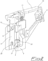
Fig.1 is a perspective front view of the actuator with the SMA wire omitted for the sake of clarity; -
Fig.2 is a vertical sectional view of the actuator ofFig.1 , taken along an almost central plane; -
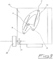
Fig.3 is a diagrammatic view showing the bistable moving system in detail; -
Figs.4a-4d are diagrammatic views showing the operation of the actuator; -
Fig.5 is a front view of a second embodiment of the actuator; and -
Fig.6 is a side view of the actuator ofFig.5 . - With reference to
figures 1 and2 , there is seen that an actuator according to the present invention includes a supporting body 1 that carries all the other components through suitable seats and couplings, these being different depending on the specific technical solutions adopted for the intended purpose of the actuator. In the particular embodiment illustrated in detail hereunder, the supporting body 1 is provided withbottom seats 3 that receivehorizontal pivot pins 5 of a mirror-holder 7 that is also provided with upperhorizontal motion pins 9. The external end of eachmotion pin 9 is connected to the top of body 1 through a pullingspring 11, while its internal end engages ashaped groove 13 formed in a centralvertical pusher 15 that slides in a correspondingcylindrical guide 17. - Pusher 15 slides upwards upon activation of a SMA wire (not shown) extending between
fixing points 19, where it is secured by lockingmembers 21 that also provide the electrical supply, and passing in anotch 23 formed in the bottom face ofpusher 15 so as to obtain a V-shaped configuration similar to that ofEP 1013503A1 but in a vertical plane (see alsoFig.5 ). When the SMA wire is deactivated, pusher 15 slides downwards under the action ofvertical torsion springs 25 mounted onpegs 27 of body 1 and whose free ends engage suitable seats (not shown) formed inpusher 15. The limits of the vertical reciprocating motion ofpusher 15 are defined bygroove 13 as will be better described further on. - In this arrangement the SMA wire is the actuating member,
pusher 15 is the driving element,motion pins 9 andgrooves 13 make up the bistable moving system and mirror-holder 7 is the driven element although, as already mentioned above, the driven element could be the mirror itself (not shown in these figures) if it is made integral withpivot pins 5 andmotion pins 9. - In the light of the description above, and referring also to
figures 3 and4a-4d , the simple and effective operation of the bistable shape memory actuator according to the present invention is readily understood. - The normal operating position illustrated in
figure 4a is considered as the starting position and reference point, this being defined by a position sensor made up of a fixedportion 29 mounted on body 1 and amobile portion 31 mounted onpusher 15. The position sensor can be of any known type suitable for the purpose, e.g. aHall sensor 29 and amagnet 31 or apotentiometer 29 and apotentiometer cursor 31. In this normal position amirror 33 mounted on mirror-holder 7 has its high-reflection surface in line with the driver's view whereas the low-reflection surface is out of line. - When the photodetecting device (not shown) detects a glare condition, the
SMA wire 35 is heated by passing a current through it by means of lockingmembers 21 so that it contracts and moves pusher 15 upwards. Due to the shape and arrangement ofgrooves 13, that have an inverted heart shape slanted forward, this upward motion ofpusher 15 results inpins 9 passing from a first stable position A to a first temporary position B, as shown inFig.3 , which in turn results in mirror-holder 7 rotating backward aroundpivot pins 5 as shown by the comparison ofFig.4a to Fig.4b . - As soon as position B is reached by
pins 9, either as detected by the position sensor or as calculated through the time of activation of theSMA wire 35, the latter is deactivated so that it cools down and re-extends to its original length thus allowing thereturn springs 25 to movepusher 15 downwards. This downward motion ofpusher 15 results inpins 9 passing from the first temporary position B to a second stable position C, which in turn results in mirror-holder 7 rotating forward aroundpivot pins 5 as shown by the comparison ofFig.4b to Fig.4c . In this second stable position C, whose reaching is verified by the position sensor,mirror 33 mounted on mirror-holder 7 has its low-reflection surface in line with the driver's view whereas the high-reflection surface is out of line thus achieving the anti-glare effect. - The reverse transition from the anti-glare position of
Fig.4c to the normal operating position ofFig.4a , always upon command of the photodetector, requires another activation of theSMA wire 35 so that it contracts and moves pusher 15 upwards, this upward motion resulting inpins 9 passing from the second stable position C to a second temporary position D, which in turn results in mirror-holder 7 rotating backward as shown by the comparison ofFig.4c to Fig.4d . - As soon as position D is reached by
pins 9, still either as detected by the position sensor or as calculated through the time of activation of theSMA wire 35 which in this case is longer, the latter is deactivated so that it cools down and re-extends to its original length thus allowing thereturn springs 25 to movepusher 15 downwards. This downward motion ofpusher 15 results inpins 9 passing from the second temporary position D to the first stable position A, which in turn results in mirror-holder 7 rotating further backward as shown by the comparison ofFig.4d to Fig.4a . Obviously, also the reaching of this stable position is verified by the position sensor. - The actuator operation described above clearly shows how the present actuator achieves the previously mentioned advantages of moving the driven element between two stable positions by activating the SMA wire only for brief shortening runs, and of allowing also a manual activation by the driver who can act directly on the bistable moving system through
pusher 15, provided that the latter projects downwards from the casing of the rear view mirror. - Finally,
figures 5 and 6 show a second embodiment of the actuator that differs from the above-described actuator in a few details, each of which can be separately applied to the first embodiment offigures 1 and2 . - A first difference resides in the replacement of the torsion springs 25 with a single vertical coiled
spring 37 that is coaxially arranged onpusher 15' at an intermediate portion thereof of reduced diameter, so thatspring 37 is compressed (i.e. loaded) against the slidingseat 17 upon contraction of theSMA wire 35. Clearly, this alternative embodiment is just exemplificative since a person skilled in the art could devise other arrangements of the spring(s) assuring the return ofpusher 15/15' or the use of any other equivalent resilient element(s). - Another difference of this second embodiment is the addition of a
coiled spring 39 coaxially arranged on theSMA wire 35 at an end portion thereof so that it can be compressed against the adjacent lockingmember 21 upon contraction of the V-shapedSMA wire 35. Thisspring 39 serves as a mechanical safety incase pusher 15' can not be moved for any reason, e.g. it is stuck inguide 17 or the bistable moving system is jammed, whereby the contraction of theSMA wire 35 would result in the rupture thereof because the shortening of the wire can not be turned into a shortening of the path between the two lockingmembers 21. Obviously, the strength ofspring 39 is selected such that in normal operation it remains uncompressed upon contraction of theSMA wire 35 thus causing the upwards sliding ofpusher 15'. - A further difference of the second actuator is the pivotable connection between
pins 9 and the top of body 1 that is provided not bysprings 11 but by a connectingmember 41 that can be either resilient or not. The side view ofFig.6 also illustrates how the lockingmembers 21 project from the back side of the supporting body 1 with contact reeds for the connection to the electronic control board located thereon. - It is clear that the above-described and illustrated embodiments of the bistable shape memory actuator according to the invention are just examples susceptible of various modifications. In particular, in addition to the above-mentioned variants, it should be noted that the bistable moving system can be of any other known type, such as those used in retractable pens, as long as it can be fitted between the driving element and the driven element and it provides the required back-and-forth oscillation of the latter merely through the reciprocating motion of the former.
- Moreover, the symmetrical arrangement of
springs pins 9 andgrooves 13, of fixingpoints 19, etc. is preferable for a smooth operation of the actuator but not strictly indispensable, whereby an asymmetrical arrangement of these elements and/or the elimination of one of them (e.g. using only onespring pin 9 and groove 13) could be conceived. Similarly, the arrangement of many elements could be reversed with substantial equivalence of operation, e.g. formingpins 9 onpusher 15 andgrooves 13 in mirror-holder 7, or formingpivot pins 5 on supporting body 1 and thecorresponding seats 3 in mirror-holder 7. - Finally, it should also be noted that in the above-described operation of the present actuator directional terms such as vertical/horizontal, upward/downward, forward/backward, etc. are referred to the specific illustrated embodiment and are not meant to be limitative since the actuator could operate also upside-down, horizontally or with any other particular orientation that a given application might require.
- Similarly, despite the fact that the detailed description in this application illustrates the present actuator applied to an automatic anti-glare rear view mirror for vehicles, this is not intended to limit in any way the possibility of applying said actuator to other devices that can benefit from the features thereof (e.g. a window opening device). Another example of application of a shape memory actuator with a bistable moving system is found in
US 2004/0104580 , where it is used in door latching devices for household appliances, such as dishwashers, to support the closure of the appliance door and to keep the door closed.
Claims (9)
- Shape memory actuator comprising a supporting body (1), a driven element (7) pivotably mounted on said supporting body (1), a SMA actuating member (35) having a V-shaped configuration and a driving element (15; 15') in permanent contact with said driven element (7) through a bistable moving system (9, 13) that allows a relative motion between said two elements (7; 15; 15'), the movement of the driven element (7) being determined by said SMA actuating member (35) and by at least one first resilient return member (25; 37) acting in opposition to the SMA actuating member (35), the driven element (7) being able to take two stable positions under the action of said bistable moving system (9, 13) connecting said driving element (15; 15') to the driven element (7) such that each toggling between said two stable positions is due to an activation of the SMA actuating member (35), characterized in that the SMA actuating member (35), the bistable moving system (9, 13), said first resilient return member (25; 37), the driving element (15; 15') and the driven element (7) are all arranged on a same side of the supporting body (1) and all of them are in a substantially co-planar arrangement with the supporting body (1).
- Shape memory actuator according to claim 1, characterized in that the SMA actuating member (35) is mounted on the supporting body (1) with a resilient member (39) that is compressible enough to absorb the contraction of the SMA actuating member (35) as an alternative to the movement of the driving element (15') in case the latter can not be moved.
- Shape memory actuator according to claim 1 or 2, characterized in that the bistable moving system (9, 13) is also pivotably connected to the supporting body (1) through at least one second resilient return member (11).
- Shape memory actuator according to any of the preceding claims, characterized in that the at least one first resilient return member acting in opposition to the SMA actuating member (35) is a coiled spring (37) that is arranged on the driving element (15') such as to be loaded upon activation of the SMA actuating member (35).
- Shape memory actuator according to any of the preceding claims, characterized in that the bistable moving system includes at least one pin (9) engaging at least one groove (13) that has a shape such that a first activation of the SMA actuating member (35) results in said pin (9) passing from a first stable position (A) to a first temporary position (B) and the subsequent deactivation of the SMA actuating member (35) results in the pin (9) passing from said first temporary position (B) to a second stable position (C) under the action of at least one second resilient return member (11), and a second activation of the SMA actuating member (35) results in the pin (9) passing from said second stable position (C) to a second temporary position (D) and the subsequent deactivation of the SMA actuating member (35) results in the pin (9) passing from said second temporary position (D) to the first stable position (A) under the action of said at least one second resilient return member (11).
- Shape memory actuator according to the preceding claim, characterized in that the supporting body (1) is provided with bottom seats (3) that receive horizontal pivot pins (5) of a driven element (7) that is also provided with upper horizontal motion pins (9) whose external ends are connected to the top of said supporting body (1) through second resilient return members (11) consisting of pulling springs while their internal end engage shaped grooves (13) formed in a central vertical pusher (15) that slides in a corresponding cylindrical guide (17) under the action of a SMA wire (35) arranged in a V-shaped configuration extending between fixing points (19), where it is secured by locking members (21) that also provide the electrical supply, and passing in a notch (23) formed in the bottom face of said pusher (15) and under the action of vertical torsion springs (25) mounted on pegs (27) of the supporting body (1) and whose free ends engage suitable seats formed in the pusher (15), the limits of the vertical reciprocating motion of the latter being defined by said shaped groove (13).
- Anti-glare rear view mirror comprising an actuator according to any of the preceding claims.
- Anti-glare rear view mirror according to the preceding claim, characterized in that it comprises a photodetecting device that upon detection of the glare condition automatically changes through the actuator the position of the reflecting surface of a mirror (33) from a high-reflecting surface to a low-reflecting surface and then automatically restores the normal operating position in the absence of glare.
- Anti-glare rear view mirror according to claim 7 or 8, characterized in that it is provided with an external mechanical control for the manual activation of the actuator.
Priority Applications (1)
| Application Number | Priority Date | Filing Date | Title |
|---|---|---|---|
| PL13801796T PL2906826T3 (en) | 2012-10-10 | 2013-10-08 | Shape memory actuator with bistable driven element |
Applications Claiming Priority (2)
| Application Number | Priority Date | Filing Date | Title |
|---|---|---|---|
| IT001705A ITMI20121705A1 (en) | 2012-10-10 | 2012-10-10 | BISTABLE ELECTRIC SWITCH WITH SHAPE MEMORY ACTUATOR |
| PCT/IB2013/059209 WO2014057423A2 (en) | 2012-10-10 | 2013-10-08 | Shape memory actuator with bistable driven element |
Publications (2)
| Publication Number | Publication Date |
|---|---|
| EP2906826A2 EP2906826A2 (en) | 2015-08-19 |
| EP2906826B1 true EP2906826B1 (en) | 2020-04-15 |
Family
ID=47324267
Family Applications (1)
| Application Number | Title | Priority Date | Filing Date |
|---|---|---|---|
| EP13801796.7A Active EP2906826B1 (en) | 2012-10-10 | 2013-10-08 | Shape memory actuator with bistable driven element |
Country Status (9)
| Country | Link |
|---|---|
| US (1) | US9630560B2 (en) |
| EP (1) | EP2906826B1 (en) |
| JP (1) | JP6333828B2 (en) |
| KR (1) | KR20150063414A (en) |
| CN (1) | CN104718376B (en) |
| ES (1) | ES2805356T3 (en) |
| IT (1) | ITMI20121705A1 (en) |
| PL (1) | PL2906826T3 (en) |
| WO (1) | WO2014057423A2 (en) |
Families Citing this family (28)
| Publication number | Priority date | Publication date | Assignee | Title |
|---|---|---|---|---|
| DE112013006786T5 (en) | 2013-03-06 | 2015-12-03 | Kongsberg Automotive Ab | Fluid flow path adjustment device with a shape memory alloy element |
| DE112013007683B4 (en) * | 2013-12-13 | 2022-01-13 | Kongsberg Automotive Ab | SMA valve for controlling the air supply to an air cell in a vehicle seat |
| DE112013007678T5 (en) | 2013-12-13 | 2016-09-15 | Kongsberg Automotive Ab | SMA valve for controlling the supply of compressed air to an air cell in a vehicle seat |
| WO2015086094A1 (en) | 2013-12-13 | 2015-06-18 | Kongsberg Automotive Ab | Sma valve for controlling air supply to an air cell in a vehicle seat |
| CN106461093B (en) | 2014-06-04 | 2019-03-05 | 康斯博格汽车股份公司 | SMA valve for controlling pressurized air supply to air chambers in vehicle seats |
| CN106572766B (en) * | 2014-06-25 | 2020-08-21 | 雀巢产品有限公司 | Food or Beverage Preparation Machines |
| US9933689B2 (en) | 2015-05-05 | 2018-04-03 | Actuator Solutions GmbH | Tilt module subassembly and optical image stabilizer comprising it |
| EP3350020B1 (en) * | 2015-09-18 | 2019-11-20 | Gentex Corporation | Toggle mechanism for rearview assembly |
| US9637064B1 (en) | 2015-10-14 | 2017-05-02 | Bendix Commercial Vehicle Systems Llc | Apparatus and method for restoring a camera mounting to a calibrated position |
| EP3184366B1 (en) | 2015-12-21 | 2018-07-04 | SMR Patents S.à.r.l. | Moveable rear view mirror comprising active material |
| US9880565B1 (en) * | 2016-10-06 | 2018-01-30 | Dolphin Fluidics S.R.L. | Two-stage valve |
| US10416471B2 (en) | 2016-10-17 | 2019-09-17 | Cymer, Llc | Spectral feature control apparatus |
| GB201703356D0 (en) | 2017-03-02 | 2017-04-19 | Cambridge Mechatronics Ltd | SMA actuator for zoom camera OIS |
| US10479234B2 (en) | 2017-06-26 | 2019-11-19 | Faurecia Automotive Seating, Llc | Actuator for an occupant support |
| CN108386329B (en) * | 2018-02-02 | 2019-11-19 | 西安电子科技大学 | A rotating mechanism driven by shape memory alloy |
| CN109932805B (en) * | 2019-03-04 | 2021-06-01 | 杭州电子科技大学 | An adaptive support method for large aperture mirrors |
| DE102019125143A1 (en) * | 2019-09-18 | 2021-03-18 | Universität des Saarlandes | Thermal actuator arrangement with improved reset time |
| KR102711025B1 (en) * | 2020-03-30 | 2024-09-27 | 사에스 게터스 에스.페.아. | Bistable shape memory alloy inertial actuator |
| CN116867967A (en) * | 2021-03-02 | 2023-10-10 | 工程吸气公司 | Asymmetric bistable shape memory alloy inertial actuator |
| US11460009B1 (en) | 2021-03-22 | 2022-10-04 | Toyota Motor Engineering & Manufacturing North America, Inc. | Actuator for holding an object |
| US12383066B2 (en) | 2022-04-26 | 2025-08-12 | Toyota Motor Engineering & Manufacturing North America, Inc. | Chair with shape memory material-based movement synchronized with visual content |
| CN114721107A (en) * | 2022-05-16 | 2022-07-08 | 上海信迈电子科技有限公司 | Optical element driving device, image pickup device, and mobile terminal |
| US11953114B2 (en) * | 2022-06-01 | 2024-04-09 | Tangtring Seating Technology Inc. | Air valve with SMA for switching |
| US12241458B2 (en) * | 2023-02-16 | 2025-03-04 | Toyota Motor Engineering & Manufacturing North America, Inc. | Actuator with contracting member |
| US12270386B2 (en) | 2023-02-16 | 2025-04-08 | Toyota Motor Engineering & Manufacturing North America, Inc. | Shape memory material member-based actuator |
| US12152570B2 (en) | 2023-02-22 | 2024-11-26 | Toyota Motor Engineering & Manufacturing North America, Inc. | Shape memory material member-based actuator with electrostatic clutch preliminary class |
| US12163507B2 (en) | 2023-02-22 | 2024-12-10 | Toyota Motor Engineering & Manufacturing North America, Inc. | Contracting member-based actuator with clutch |
| US12234811B1 (en) | 2023-08-21 | 2025-02-25 | Toyota Motor Engineering & Manufacturing North America, Inc. | Monitoring a state of a shape memory material member |
Family Cites Families (16)
| Publication number | Priority date | Publication date | Assignee | Title |
|---|---|---|---|---|
| US3634803A (en) * | 1969-07-22 | 1972-01-11 | Robertshaw Controls Co | Temperature-responsive switch assemblies |
| JPS61177179A (en) * | 1985-01-30 | 1986-08-08 | Kojima Press Co Ltd | Shape memory alloy actuator |
| JPS626847A (en) * | 1985-07-03 | 1987-01-13 | Ichikoh Ind Ltd | Auto-dimming mirror device |
| JPS6412077A (en) * | 1987-07-06 | 1989-01-17 | Furukawa Electric Co Ltd | Actuator |
| BR9907938A (en) * | 1998-02-17 | 2000-11-14 | Magna Mirror Systems Inc | Assembly of reflected light reduction mirror for a vehicle |
| US6364496B1 (en) * | 1998-10-23 | 2002-04-02 | Magna Mirror Systems, Inc. | Shape memory alloy rearview mirror |
| IT1305590B1 (en) * | 1998-12-23 | 2001-05-09 | Magneti Marelli Spa | REAR-VIEW MIRROR FOR MOTOR VEHICLES WITH ACTUATOR-CLOTHING DEVICE, WITH MEMORY OF SHAPE. |
| ITTO20010248A1 (en) * | 2001-03-16 | 2002-09-16 | Fiat Ricerche | SHAPE MEMORY ACTUATOR, BISTABLE OPERATION. |
| DE50214001D1 (en) * | 2002-02-27 | 2009-12-31 | Emz Hanauer Gmbh & Co Kgaa | Unit with memory metal actuator for door locks of household appliances |
| US20050160858A1 (en) * | 2002-07-24 | 2005-07-28 | M 2 Medical A/S | Shape memory alloy actuator |
| KR20060032587A (en) * | 2003-09-09 | 2006-04-17 | 델피 테크놀로지스 인코포레이티드 | Electric actuator with smart muscle wire |
| ATE331138T1 (en) * | 2004-05-03 | 2006-07-15 | Fiat Ricerche | BISTABLE SWITCH WITH SHAPE MEMORY METAL |
| ATE360761T1 (en) * | 2004-12-30 | 2007-05-15 | Fiat Ricerche | SHAPE MEMORY ACTUATOR WITH SURGE VOLTAGE DAMAGE PROTECTION |
| US7779715B2 (en) * | 2006-07-05 | 2010-08-24 | Grand Haven Stamped Products, A Division Of Jsj Corporation | Shifter with actuator incorporating magnetic unlock mechanism |
| ITMI20071283A1 (en) * | 2007-06-27 | 2008-12-28 | Getters Spa | ACTUATOR INCLUDING ALLOY ELEMENTS IN SHAPE MEMORY WITH EXTENDED TEMPERATURE RANGE OF USE |
| DE102008027541B4 (en) * | 2008-06-10 | 2017-04-06 | Günther Zimmer | Actuating device for pieces of furniture with at least one shape memory element |
-
2012
- 2012-10-10 IT IT001705A patent/ITMI20121705A1/en unknown
-
2013
- 2013-10-08 JP JP2015536262A patent/JP6333828B2/en active Active
- 2013-10-08 EP EP13801796.7A patent/EP2906826B1/en active Active
- 2013-10-08 US US14/434,082 patent/US9630560B2/en active Active
- 2013-10-08 WO PCT/IB2013/059209 patent/WO2014057423A2/en not_active Ceased
- 2013-10-08 ES ES13801796T patent/ES2805356T3/en active Active
- 2013-10-08 KR KR1020157008885A patent/KR20150063414A/en not_active Withdrawn
- 2013-10-08 PL PL13801796T patent/PL2906826T3/en unknown
- 2013-10-08 CN CN201380053192.6A patent/CN104718376B/en active Active
Non-Patent Citations (1)
| Title |
|---|
| None * |
Also Published As
| Publication number | Publication date |
|---|---|
| JP6333828B2 (en) | 2018-05-30 |
| CN104718376B (en) | 2018-09-04 |
| WO2014057423A3 (en) | 2014-10-30 |
| JP2016500782A (en) | 2016-01-14 |
| EP2906826A2 (en) | 2015-08-19 |
| US9630560B2 (en) | 2017-04-25 |
| PL2906826T3 (en) | 2020-11-16 |
| US20150274078A1 (en) | 2015-10-01 |
| ITMI20121705A1 (en) | 2014-04-11 |
| CN104718376A (en) | 2015-06-17 |
| WO2014057423A2 (en) | 2014-04-17 |
| KR20150063414A (en) | 2015-06-09 |
| ES2805356T3 (en) | 2021-02-11 |
Similar Documents
| Publication | Publication Date | Title |
|---|---|---|
| EP2906826B1 (en) | Shape memory actuator with bistable driven element | |
| CN105164412B (en) | Shape memory actuator with multistable driven elements | |
| JP4732417B2 (en) | Movable holder | |
| JP5026583B2 (en) | Door opening / closing stay | |
| CN103035427B (en) | Reconfigurable bistable device | |
| KR101049035B1 (en) | Sliding mechanism for portable devices | |
| EP1939906B1 (en) | Electrical switch | |
| US7697280B2 (en) | Sliding mechanism for portable electronic device | |
| CN101030985B (en) | Portable electronic device | |
| CN101170884B (en) | Slide module and portable terminal having the same | |
| CN110087949B (en) | Mechanical tilting for full display mirror | |
| RU2008135162A (en) | LOCKING SPINDLE LOCKING MECHANISM | |
| KR100606771B1 (en) | Height adjustment stand for the monitor | |
| KR100628499B1 (en) | Slider of Automotive Window Regulator | |
| KR200397455Y1 (en) | Sliding apparatus for mobile phone | |
| US20140292473A1 (en) | Actuator device with stable working positions | |
| EP1768145B1 (en) | Control device comprising a mechanism of friction point and actuating electrical contacts | |
| JP2014129645A (en) | Catch body of sliding door slide shock absorber | |
| US20030091345A1 (en) | Camera with a focus retaining mechanism | |
| JPH03217358A (en) | Wiping range switching device in windshield wiper | |
| HK1153252B (en) | Stay for opening and closing of door |
Legal Events
| Date | Code | Title | Description |
|---|---|---|---|
| PUAI | Public reference made under article 153(3) epc to a published international application that has entered the european phase |
Free format text: ORIGINAL CODE: 0009012 |
|
| 17P | Request for examination filed |
Effective date: 20150420 |
|
| AK | Designated contracting states |
Kind code of ref document: A2 Designated state(s): AL AT BE BG CH CY CZ DE DK EE ES FI FR GB GR HR HU IE IS IT LI LT LU LV MC MK MT NL NO PL PT RO RS SE SI SK SM TR |
|
| AX | Request for extension of the european patent |
Extension state: BA ME |
|
| DAX | Request for extension of the european patent (deleted) | ||
| 17Q | First examination report despatched |
Effective date: 20160429 |
|
| STAA | Information on the status of an ep patent application or granted ep patent |
Free format text: STATUS: EXAMINATION IS IN PROGRESS |
|
| GRAP | Despatch of communication of intention to grant a patent |
Free format text: ORIGINAL CODE: EPIDOSNIGR1 |
|
| STAA | Information on the status of an ep patent application or granted ep patent |
Free format text: STATUS: GRANT OF PATENT IS INTENDED |
|
| INTG | Intention to grant announced |
Effective date: 20191122 |
|
| GRAS | Grant fee paid |
Free format text: ORIGINAL CODE: EPIDOSNIGR3 |
|
| GRAA | (expected) grant |
Free format text: ORIGINAL CODE: 0009210 |
|
| STAA | Information on the status of an ep patent application or granted ep patent |
Free format text: STATUS: THE PATENT HAS BEEN GRANTED |
|
| AK | Designated contracting states |
Kind code of ref document: B1 Designated state(s): AL AT BE BG CH CY CZ DE DK EE ES FI FR GB GR HR HU IE IS IT LI LT LU LV MC MK MT NL NO PL PT RO RS SE SI SK SM TR |
|
| REG | Reference to a national code |
Ref country code: CH Ref legal event code: EP |
|
| REG | Reference to a national code |
Ref country code: DE Ref legal event code: R096 Ref document number: 602013067994 Country of ref document: DE |
|
| REG | Reference to a national code |
Ref country code: IE Ref legal event code: FG4D |
|
| REG | Reference to a national code |
Ref country code: AT Ref legal event code: REF Ref document number: 1257600 Country of ref document: AT Kind code of ref document: T Effective date: 20200515 |
|
| REG | Reference to a national code |
Ref country code: NL Ref legal event code: MP Effective date: 20200415 |
|
| REG | Reference to a national code |
Ref country code: LT Ref legal event code: MG4D |
|
| PG25 | Lapsed in a contracting state [announced via postgrant information from national office to epo] |
Ref country code: NO Free format text: LAPSE BECAUSE OF FAILURE TO SUBMIT A TRANSLATION OF THE DESCRIPTION OR TO PAY THE FEE WITHIN THE PRESCRIBED TIME-LIMIT Effective date: 20200715 Ref country code: GR Free format text: LAPSE BECAUSE OF FAILURE TO SUBMIT A TRANSLATION OF THE DESCRIPTION OR TO PAY THE FEE WITHIN THE PRESCRIBED TIME-LIMIT Effective date: 20200716 Ref country code: IS Free format text: LAPSE BECAUSE OF FAILURE TO SUBMIT A TRANSLATION OF THE DESCRIPTION OR TO PAY THE FEE WITHIN THE PRESCRIBED TIME-LIMIT Effective date: 20200815 Ref country code: FI Free format text: LAPSE BECAUSE OF FAILURE TO SUBMIT A TRANSLATION OF THE DESCRIPTION OR TO PAY THE FEE WITHIN THE PRESCRIBED TIME-LIMIT Effective date: 20200415 Ref country code: NL Free format text: LAPSE BECAUSE OF FAILURE TO SUBMIT A TRANSLATION OF THE DESCRIPTION OR TO PAY THE FEE WITHIN THE PRESCRIBED TIME-LIMIT Effective date: 20200415 Ref country code: PT Free format text: LAPSE BECAUSE OF FAILURE TO SUBMIT A TRANSLATION OF THE DESCRIPTION OR TO PAY THE FEE WITHIN THE PRESCRIBED TIME-LIMIT Effective date: 20200817 Ref country code: SE Free format text: LAPSE BECAUSE OF FAILURE TO SUBMIT A TRANSLATION OF THE DESCRIPTION OR TO PAY THE FEE WITHIN THE PRESCRIBED TIME-LIMIT Effective date: 20200415 Ref country code: LT Free format text: LAPSE BECAUSE OF FAILURE TO SUBMIT A TRANSLATION OF THE DESCRIPTION OR TO PAY THE FEE WITHIN THE PRESCRIBED TIME-LIMIT Effective date: 20200415 |
|
| REG | Reference to a national code |
Ref country code: AT Ref legal event code: MK05 Ref document number: 1257600 Country of ref document: AT Kind code of ref document: T Effective date: 20200415 |
|
| PG25 | Lapsed in a contracting state [announced via postgrant information from national office to epo] |
Ref country code: HR Free format text: LAPSE BECAUSE OF FAILURE TO SUBMIT A TRANSLATION OF THE DESCRIPTION OR TO PAY THE FEE WITHIN THE PRESCRIBED TIME-LIMIT Effective date: 20200415 Ref country code: BG Free format text: LAPSE BECAUSE OF FAILURE TO SUBMIT A TRANSLATION OF THE DESCRIPTION OR TO PAY THE FEE WITHIN THE PRESCRIBED TIME-LIMIT Effective date: 20200715 Ref country code: RS Free format text: LAPSE BECAUSE OF FAILURE TO SUBMIT A TRANSLATION OF THE DESCRIPTION OR TO PAY THE FEE WITHIN THE PRESCRIBED TIME-LIMIT Effective date: 20200415 Ref country code: LV Free format text: LAPSE BECAUSE OF FAILURE TO SUBMIT A TRANSLATION OF THE DESCRIPTION OR TO PAY THE FEE WITHIN THE PRESCRIBED TIME-LIMIT Effective date: 20200415 |
|
| PG25 | Lapsed in a contracting state [announced via postgrant information from national office to epo] |
Ref country code: AL Free format text: LAPSE BECAUSE OF FAILURE TO SUBMIT A TRANSLATION OF THE DESCRIPTION OR TO PAY THE FEE WITHIN THE PRESCRIBED TIME-LIMIT Effective date: 20200415 |
|
| REG | Reference to a national code |
Ref country code: DE Ref legal event code: R097 Ref document number: 602013067994 Country of ref document: DE |
|
| PG25 | Lapsed in a contracting state [announced via postgrant information from national office to epo] |
Ref country code: DK Free format text: LAPSE BECAUSE OF FAILURE TO SUBMIT A TRANSLATION OF THE DESCRIPTION OR TO PAY THE FEE WITHIN THE PRESCRIBED TIME-LIMIT Effective date: 20200415 Ref country code: EE Free format text: LAPSE BECAUSE OF FAILURE TO SUBMIT A TRANSLATION OF THE DESCRIPTION OR TO PAY THE FEE WITHIN THE PRESCRIBED TIME-LIMIT Effective date: 20200415 Ref country code: AT Free format text: LAPSE BECAUSE OF FAILURE TO SUBMIT A TRANSLATION OF THE DESCRIPTION OR TO PAY THE FEE WITHIN THE PRESCRIBED TIME-LIMIT Effective date: 20200415 Ref country code: SM Free format text: LAPSE BECAUSE OF FAILURE TO SUBMIT A TRANSLATION OF THE DESCRIPTION OR TO PAY THE FEE WITHIN THE PRESCRIBED TIME-LIMIT Effective date: 20200415 Ref country code: RO Free format text: LAPSE BECAUSE OF FAILURE TO SUBMIT A TRANSLATION OF THE DESCRIPTION OR TO PAY THE FEE WITHIN THE PRESCRIBED TIME-LIMIT Effective date: 20200415 Ref country code: CZ Free format text: LAPSE BECAUSE OF FAILURE TO SUBMIT A TRANSLATION OF THE DESCRIPTION OR TO PAY THE FEE WITHIN THE PRESCRIBED TIME-LIMIT Effective date: 20200415 |
|
| REG | Reference to a national code |
Ref country code: ES Ref legal event code: FG2A Ref document number: 2805356 Country of ref document: ES Kind code of ref document: T3 Effective date: 20210211 |
|
| PLBE | No opposition filed within time limit |
Free format text: ORIGINAL CODE: 0009261 |
|
| STAA | Information on the status of an ep patent application or granted ep patent |
Free format text: STATUS: NO OPPOSITION FILED WITHIN TIME LIMIT |
|
| PG25 | Lapsed in a contracting state [announced via postgrant information from national office to epo] |
Ref country code: SK Free format text: LAPSE BECAUSE OF FAILURE TO SUBMIT A TRANSLATION OF THE DESCRIPTION OR TO PAY THE FEE WITHIN THE PRESCRIBED TIME-LIMIT Effective date: 20200415 |
|
| 26N | No opposition filed |
Effective date: 20210118 |
|
| PG25 | Lapsed in a contracting state [announced via postgrant information from national office to epo] |
Ref country code: SI Free format text: LAPSE BECAUSE OF FAILURE TO SUBMIT A TRANSLATION OF THE DESCRIPTION OR TO PAY THE FEE WITHIN THE PRESCRIBED TIME-LIMIT Effective date: 20200415 |
|
| REG | Reference to a national code |
Ref country code: CH Ref legal event code: PL |
|
| GBPC | Gb: european patent ceased through non-payment of renewal fee |
Effective date: 20201008 |
|
| PG25 | Lapsed in a contracting state [announced via postgrant information from national office to epo] |
Ref country code: MC Free format text: LAPSE BECAUSE OF FAILURE TO SUBMIT A TRANSLATION OF THE DESCRIPTION OR TO PAY THE FEE WITHIN THE PRESCRIBED TIME-LIMIT Effective date: 20200415 Ref country code: LU Free format text: LAPSE BECAUSE OF NON-PAYMENT OF DUE FEES Effective date: 20201008 |
|
| REG | Reference to a national code |
Ref country code: BE Ref legal event code: MM Effective date: 20201031 |
|
| PG25 | Lapsed in a contracting state [announced via postgrant information from national office to epo] |
Ref country code: GB Free format text: LAPSE BECAUSE OF NON-PAYMENT OF DUE FEES Effective date: 20201008 Ref country code: LI Free format text: LAPSE BECAUSE OF NON-PAYMENT OF DUE FEES Effective date: 20201031 Ref country code: CH Free format text: LAPSE BECAUSE OF NON-PAYMENT OF DUE FEES Effective date: 20201031 Ref country code: BE Free format text: LAPSE BECAUSE OF NON-PAYMENT OF DUE FEES Effective date: 20201031 |
|
| PG25 | Lapsed in a contracting state [announced via postgrant information from national office to epo] |
Ref country code: IE Free format text: LAPSE BECAUSE OF NON-PAYMENT OF DUE FEES Effective date: 20201008 |
|
| PG25 | Lapsed in a contracting state [announced via postgrant information from national office to epo] |
Ref country code: MT Free format text: LAPSE BECAUSE OF FAILURE TO SUBMIT A TRANSLATION OF THE DESCRIPTION OR TO PAY THE FEE WITHIN THE PRESCRIBED TIME-LIMIT Effective date: 20200415 Ref country code: CY Free format text: LAPSE BECAUSE OF FAILURE TO SUBMIT A TRANSLATION OF THE DESCRIPTION OR TO PAY THE FEE WITHIN THE PRESCRIBED TIME-LIMIT Effective date: 20200415 |
|
| PG25 | Lapsed in a contracting state [announced via postgrant information from national office to epo] |
Ref country code: MK Free format text: LAPSE BECAUSE OF FAILURE TO SUBMIT A TRANSLATION OF THE DESCRIPTION OR TO PAY THE FEE WITHIN THE PRESCRIBED TIME-LIMIT Effective date: 20200415 |
|
| P01 | Opt-out of the competence of the unified patent court (upc) registered |
Effective date: 20230515 |
|
| PGFP | Annual fee paid to national office [announced via postgrant information from national office to epo] |
Ref country code: PL Payment date: 20250930 Year of fee payment: 13 Ref country code: TR Payment date: 20250930 Year of fee payment: 13 |
|
| PGFP | Annual fee paid to national office [announced via postgrant information from national office to epo] |
Ref country code: DE Payment date: 20251020 Year of fee payment: 13 |
|
| PGFP | Annual fee paid to national office [announced via postgrant information from national office to epo] |
Ref country code: IT Payment date: 20251031 Year of fee payment: 13 |
|
| PGFP | Annual fee paid to national office [announced via postgrant information from national office to epo] |
Ref country code: FR Payment date: 20251029 Year of fee payment: 13 |
|
| PGFP | Annual fee paid to national office [announced via postgrant information from national office to epo] |
Ref country code: ES Payment date: 20251114 Year of fee payment: 13 |