EP2906824B1 - Method for operating a wind turbine - Google Patents
Method for operating a wind turbine Download PDFInfo
- Publication number
- EP2906824B1 EP2906824B1 EP13770459.9A EP13770459A EP2906824B1 EP 2906824 B1 EP2906824 B1 EP 2906824B1 EP 13770459 A EP13770459 A EP 13770459A EP 2906824 B1 EP2906824 B1 EP 2906824B1
- Authority
- EP
- European Patent Office
- Prior art keywords
- wind turbine
- wind
- speed
- oscillation
- rotational speed
- Prior art date
- Legal status (The legal status is an assumption and is not a legal conclusion. Google has not performed a legal analysis and makes no representation as to the accuracy of the status listed.)
- Active
Links
- 238000000034 method Methods 0.000 title claims description 33
- 230000010355 oscillation Effects 0.000 claims description 20
- 230000008014 freezing Effects 0.000 claims description 13
- 238000007710 freezing Methods 0.000 claims description 13
- 230000005284 excitation Effects 0.000 claims description 10
- 230000001360 synchronised effect Effects 0.000 claims description 7
- 230000007704 transition Effects 0.000 claims description 2
- 230000000977 initiatory effect Effects 0.000 claims 1
- 238000009434 installation Methods 0.000 description 55
- 238000012360 testing method Methods 0.000 description 10
- 238000010606 normalization Methods 0.000 description 6
- 230000001133 acceleration Effects 0.000 description 3
- 238000005259 measurement Methods 0.000 description 3
- 230000001276 controlling effect Effects 0.000 description 2
- 238000013016 damping Methods 0.000 description 2
- 230000000694 effects Effects 0.000 description 2
- 238000005516 engineering process Methods 0.000 description 2
- 230000001960 triggered effect Effects 0.000 description 2
- 229910000831 Steel Inorganic materials 0.000 description 1
- 238000013459 approach Methods 0.000 description 1
- 238000006243 chemical reaction Methods 0.000 description 1
- 238000010276 construction Methods 0.000 description 1
- 230000006735 deficit Effects 0.000 description 1
- 230000001419 dependent effect Effects 0.000 description 1
- 238000001514 detection method Methods 0.000 description 1
- 238000006073 displacement reaction Methods 0.000 description 1
- 230000007774 longterm Effects 0.000 description 1
- 238000012423 maintenance Methods 0.000 description 1
- 230000000737 periodic effect Effects 0.000 description 1
- 230000001105 regulatory effect Effects 0.000 description 1
- 230000000717 retained effect Effects 0.000 description 1
- 230000033764 rhythmic process Effects 0.000 description 1
- 239000010959 steel Substances 0.000 description 1
- XLYOFNOQVPJJNP-UHFFFAOYSA-N water Substances O XLYOFNOQVPJJNP-UHFFFAOYSA-N 0.000 description 1
Images

Classifications
-
- F—MECHANICAL ENGINEERING; LIGHTING; HEATING; WEAPONS; BLASTING
- F03—MACHINES OR ENGINES FOR LIQUIDS; WIND, SPRING, OR WEIGHT MOTORS; PRODUCING MECHANICAL POWER OR A REACTIVE PROPULSIVE THRUST, NOT OTHERWISE PROVIDED FOR
- F03D—WIND MOTORS
- F03D7/00—Controlling wind motors
- F03D7/02—Controlling wind motors the wind motors having rotation axis substantially parallel to the air flow entering the rotor
- F03D7/022—Adjusting aerodynamic properties of the blades
- F03D7/0224—Adjusting blade pitch
-
- F—MECHANICAL ENGINEERING; LIGHTING; HEATING; WEAPONS; BLASTING
- F03—MACHINES OR ENGINES FOR LIQUIDS; WIND, SPRING, OR WEIGHT MOTORS; PRODUCING MECHANICAL POWER OR A REACTIVE PROPULSIVE THRUST, NOT OTHERWISE PROVIDED FOR
- F03D—WIND MOTORS
- F03D7/00—Controlling wind motors
- F03D7/02—Controlling wind motors the wind motors having rotation axis substantially parallel to the air flow entering the rotor
- F03D7/0204—Controlling wind motors the wind motors having rotation axis substantially parallel to the air flow entering the rotor for orientation in relation to wind direction
-
- F—MECHANICAL ENGINEERING; LIGHTING; HEATING; WEAPONS; BLASTING
- F03—MACHINES OR ENGINES FOR LIQUIDS; WIND, SPRING, OR WEIGHT MOTORS; PRODUCING MECHANICAL POWER OR A REACTIVE PROPULSIVE THRUST, NOT OTHERWISE PROVIDED FOR
- F03D—WIND MOTORS
- F03D7/00—Controlling wind motors
- F03D7/02—Controlling wind motors the wind motors having rotation axis substantially parallel to the air flow entering the rotor
- F03D7/04—Automatic control; Regulation
- F03D7/042—Automatic control; Regulation by means of an electrical or electronic controller
- F03D7/048—Automatic control; Regulation by means of an electrical or electronic controller controlling wind farms
-
- F—MECHANICAL ENGINEERING; LIGHTING; HEATING; WEAPONS; BLASTING
- F03—MACHINES OR ENGINES FOR LIQUIDS; WIND, SPRING, OR WEIGHT MOTORS; PRODUCING MECHANICAL POWER OR A REACTIVE PROPULSIVE THRUST, NOT OTHERWISE PROVIDED FOR
- F03D—WIND MOTORS
- F03D9/00—Adaptations of wind motors for special use; Combinations of wind motors with apparatus driven thereby; Wind motors specially adapted for installation in particular locations
- F03D9/20—Wind motors characterised by the driven apparatus
- F03D9/25—Wind motors characterised by the driven apparatus the apparatus being an electrical generator
- F03D9/255—Wind motors characterised by the driven apparatus the apparatus being an electrical generator connected to electrical distribution networks; Arrangements therefor
- F03D9/257—Wind motors characterised by the driven apparatus the apparatus being an electrical generator connected to electrical distribution networks; Arrangements therefor the wind motor being part of a wind farm
-
- F—MECHANICAL ENGINEERING; LIGHTING; HEATING; WEAPONS; BLASTING
- F05—INDEXING SCHEMES RELATING TO ENGINES OR PUMPS IN VARIOUS SUBCLASSES OF CLASSES F01-F04
- F05B—INDEXING SCHEME RELATING TO WIND, SPRING, WEIGHT, INERTIA OR LIKE MOTORS, TO MACHINES OR ENGINES FOR LIQUIDS COVERED BY SUBCLASSES F03B, F03D AND F03G
- F05B2260/00—Function
- F05B2260/96—Preventing, counteracting or reducing vibration or noise
-
- Y—GENERAL TAGGING OF NEW TECHNOLOGICAL DEVELOPMENTS; GENERAL TAGGING OF CROSS-SECTIONAL TECHNOLOGIES SPANNING OVER SEVERAL SECTIONS OF THE IPC; TECHNICAL SUBJECTS COVERED BY FORMER USPC CROSS-REFERENCE ART COLLECTIONS [XRACs] AND DIGESTS
- Y02—TECHNOLOGIES OR APPLICATIONS FOR MITIGATION OR ADAPTATION AGAINST CLIMATE CHANGE
- Y02E—REDUCTION OF GREENHOUSE GAS [GHG] EMISSIONS, RELATED TO ENERGY GENERATION, TRANSMISSION OR DISTRIBUTION
- Y02E10/00—Energy generation through renewable energy sources
- Y02E10/70—Wind energy
- Y02E10/72—Wind turbines with rotation axis in wind direction
Definitions
- the present invention relates to a method for operating at least one wind turbine. Furthermore, the present invention relates to a wind energy plant and it relates to a wind farm. It also relates to a method for operating a wind farm.
- Wind energy installations are generally known; they convert mechanical energy from wind into electrical energy, in particular by means of a rotor which rotates about an essentially horizontal axis, with an electrical generator also being used.
- An example of such a wind turbine is shown schematically in 1 shown.
- a transverse vibration is one that occurs essentially transverse to the orientation of the rotor axis. Such a transverse vibration is often caused by imbalances in the rotor and oscillates in accordance with the speed of the rotor. Since this imbalance during rotation immediately triggers this vibration, one can also speak of a forced vibration here.
- Longitudinal vibration occurs essentially in the longitudinal direction of the axis of rotation of the rotor.
- the wind turbine then swings back and forth, as it were.
- Such longitudinal vibrations are usually generated by the wind and regularly interact with the properties of the wind turbine.
- the oscillation frequency of such a longitudinal oscillation is regularly based on a natural frequency or a resonant frequency—which are usually very similar—or a multiple thereof.
- the wind itself is unstable, it can excite such a longitudinal oscillation.
- Longitudinal vibration can also occur or be amplified by the wind turbine reacting to an increase in wind in terms of control technology, including to a gust, thereby influencing the movement of the wind energy installation, with the reaction of the wind energy installation to this control intervention again bringing about a further change, which in the worst case can lead to an upswing.
- a further problem which is also the basis of the present invention and which may not have been recognized in the prior art, can occur when there are a number of wind energy installations that influence one another.
- a phenomenon is considered here in which a first wind energy installation is in a specific operating state, in particular with a specific wind direction in the lee behind a second wind energy installation.
- vibrations can also be transmitted from the front, ie second, wind energy installation to the rear, ie first wind energy installation, or only be triggered in the rear wind energy installation.
- German Patent and Trademark Office has researched the following prior art in the priority application: DE 10 2006 001 613 A1 , DE 10 2008 009 740 A1 , DE 10 2009 039 340 A1 , DE 699 01 876 T2 , U.S. 2009/0200804 A1 , WO 2007/089136 A2 and WO 2012/125842 A2 .
- a method according to claim 1 is proposed. Such a method relates at least to the operation of at least one first wind turbine. Taking into account a second wind energy installation or even further wind energy installations can make sense, but does not necessarily have to depend on a second wind energy installation, depending on the specific vibration that occurs. Finally, at least according to one embodiment, the method can also be implemented on a single wind turbine, even if the problems addressed are possibly first generated or amplified by a further wind turbine. The proposed method preferably manages without determining the specific cause of the vibrations that is to be eliminated.
- the vibration reduction measure which proposes switching the operating modes, namely switching between two power curves
- the procedure is preferably such that the rear, that is to say the first, wind energy installation runs at a lower, in particular reduced, speed. In this respect, that wind energy installation would also have its power characteristic curve or its speed changed, which also has the problematic longitudinal vibrations.
- a pitch-controlled wind energy installation is present.
- Such is equipped with a control algorithm that sets the pitch angle depending on very different specifications.
- this control algorithm constantly runs along with the operation of the wind energy installation and can lead to a constant tracking of the pitch angle, which can also be desired.
- the pure control algorithm constantly specifies a desired pitch value, which is implemented by one or more pitch drives for each individual rotor blade or possibly for all.
- this setpoint is set to a fixed value when the current pitch angle is frozen.
- the control algorithm for pitching continues to run unchanged and, if necessary, constantly calculates a new pitch angle target value.
- This desired pitch value which is now recalculated by the control algorithm within this freezing period, is not passed on, however.
- the internal implementation can also be carried out differently.
- any upswing rhythm that has set in can be interrupted.
- This proposed measure is also based on the knowledge that such longitudinal vibrations occur comparatively seldom and, in most cases, very many circumstances must occur at the same time for them to occur, at least that is what can be assumed. After the predetermined freezing period has elapsed, there is no longer a situation in which such a build-up of a longitudinal vibration occurs or is excited. This measure of short-term freezing can then usually remain a one-time measure and may not have to be repeated in the near future. It may even represent a one-time procedure during the lifetime of the wind turbine.
- the freezing period can be chosen to be comparatively short and is preferably in the range from 5 s to 1 min, in particular in the range from 10 to 20 s.
- This measure for reducing vibration by freezing the pitch angle aims to interrupt the swinging up once and thereby creates a new requirement to create in which the longitudinal vibration regularly no longer oscillates and thus no longer exceeds the predetermined limit value.
- the predetermined limit value can be a path amplitude of the oscillation path of the tower, for example in the area of the top of the tower, or also a maximum acceleration.
- the pitch control is basically carried out using a basic pitch control algorithm or standard pitch control algorithm.
- the pitch control algorithm is only changed if the longitudinal vibration occurs and the amplitude exceeds the predetermined limit value.
- a second alternative pitch control algorithm can be stored for this purpose, or only a time parameter in the control algorithm is changed.
- the pitch control algorithm can be changed in such a way that the control speed is reduced. For example, a control time constant 10% or increased by 20%.
- the azimuth angle is preferably adjusted in the range from 2 to 8°, in particular in the range from 4 to 5°. Such a small value can already prevent such an oscillation and at the same time any resulting loss of yield due to the azimuth angle that is no longer optimally set is small. It can be assumed that the reduced yield due to a non-optimal azimuth angle is reduced by the cosine of this non-optimal azimuth angle. Since the cosine hardly changes in the range from 0, i.e. up to 8°, there is hardly any reduction in yield. It may not even be detectable.
- the azimuth angle can be reset to the optimum value when the longitudinal vibration has settled down and its amplitude is significantly below the predetermined limit value, or as an additional or alternative criterion it can take into account a predetermined waiting time of, for example, one minute or five minutes before the azimuth position is restored is reset. Additionally or alternatively, the azimuth position can be set to the nominal value when the wind direction changes turned, at least turned something. Then it is to be expected that a cause of vibration dependent on the wind direction is no longer present and the wind turbine can be operated normally again with regard to its azimuth angle. This new nominal azimuth angle is then in any case no longer the azimuth angle from which the wind energy installation was adjusted to reduce vibration. Such an adjustment of the azimuth angle is proposed in particular when a first wind energy installation is located exactly in the lee of another.
- the operation of the first wind energy installation is switched from a first to a second operating mode.
- the first operating mode is based on a first performance curve and the second operating mode is based on a second performance curve.
- the power characteristic indicates a relationship between power and speed, and in particular the power is set as a function of the speed. Power is therefore set to the applicable value of the characteristic curve until the speed maintains its value there.
- Such a change by changing the operating mode can be small and changes a parameter of the wind energy installation in such a way that the starting position, which must ultimately also have led to the longitudinal oscillation, is changed. After a predetermined time has elapsed, it is possible to switch back to the first, in particular the standard, power characteristic.
- the change in the performance curve can, for example, lead to a slight change in the speed from the previous value. This may be sufficient to interrupt longitudinal vibration.
- the current pitch angle is frozen and/or the pitch control algorithm used is changed in full-load operation.
- Full-load operation describes the situation in which the prevailing wind speed is rated speed, the power generated is rated power and/or the speed is approximately rated speed.
- the pitch angle is used regularly to keep the speed constant. So if the actual speed deviates minimally from the set speed, namely usually the nominal speed, an attempt is made to counteract or regulate by adjusting the pitch angle. Longitudinal vibrations that arise as a result of this should be reduced or eliminated by freezing the pitch angle and/or changing the modified pitch algorithm, and these measures are therefore proposed in full-load operation.
- the measure of adjusting the azimuth position, switching over the operation of the first wind energy installation and/or changing the speed of the first wind energy installation takes place in part-load operation.
- Part-load operation occurs when the prevailing wind speed is below the nominal wind speed.
- the pitch angle can be set to a constant value. Freezing the pitch angle or changing a pitch algorithm that does not work here therefore makes less sense, whereas a different speed can then be set and/or a different power characteristic can be selected.
- the specific speed and also the specific power depends on the prevailing wind and constantly changes with it. This constant speed and/or change in output is taken into account here and it is therefore proposed to switch over the operation and/or to change the speed.
- Adjusting the azimuth position can also be useful here, especially since the winds are weaker. However, the azimuth position can also be adjusted in full-load operation.
- a shift in the performance characteristic, in particular the second performance characteristic, in the area of a transition from the part-load range to the full-load range is preferably proposed.
- precisely in the transitional area when some of the proposed measures do not work or have a poor effect, an improved or additional possibility of intervention can be created by shifting the characteristic curve in this area.
- a wind farm with at least a first wind power plant and a second wind power plant for generating electrical energy from wind is proposed, the first wind power plant being operated with a method according to at least one of the aforementioned embodiments.
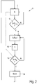
- FIG. 2 shows a simplified flow chart 2 that starts with a measuring block 4 .
- a longitudinal vibration is detected in the measuring block 4, for example from an acceleration amplitude, which can be measured with corresponding acceleration sensors on the top of the tower.
- the detected longitudinal vibration is identified in the measuring block 4 with the letter S.
- flowchart 2 shows a measurement block 4, which is at the beginning of the process described, the vibration amplitude is constantly recorded and therefore also continues to be recorded, even during the waiting time according to the waiting block 10 shown symbolically a current value of the longitudinal vibration S. This is illustrated by the dashed line with an arrow from the measurement block 4 to the second test block 12 .
- FIG 3 shows a very specific situation in which the wind 36 or the wind direction 36 is directed towards the second wind turbine 32 such that, seen from this wind direction 36, the first wind turbine 31 is operated exactly behind the second wind turbine 32.
- two helices 38 are indicated in dashed lines, which are intended to illustrate how the wind 36 hitting the second wind energy installation 32 is changed by this second wind energy installation 32 and continues its course to the first wind energy installation 31 .
- the helices 38 are essentially intended to illustrate that the first wind turbine 31 is not alone in the lee of the second wind turbine 32, but also that the quality or type of wind flow is changed by the second wind turbine 32 and the first wind turbine 31 changes accordingly.
- a longitudinal vibration 40 is illustrated by a double arrow in the first wind energy installation 31 .
- the first wind turbine 31 is in 3 additionally drawn in as a twisted first wind energy installation 41 with dashed lines.
- this rotation namely rotation or displacement in azimuth position or azimuth orientation, is for illustrative purposes only.
- the angle actually shown is comparatively large and will usually be set smaller in practical implementation.
- the twisted wind energy installation 41 shown in dashed lines is intended to make it clear, particularly taking into account the illustrated helices 38, that the wind changed by the second wind energy installation 32 reaches the wind energy installation 41 with the changed azimuth position in a completely different way. In particular, any turbulence reaches the wind turbine at different times.
- a measure for reducing, avoiding or interrupting or ending an excessive longitudinal vibration of a wind turbine is proposed, which is essentially based on the approach of proposing a short-term change in the operating behavior of the wind turbine, with the wind turbine in question being switched back into operation after the successful completion of such a measure can return to its previous operating mode or continue to operate normally.
- This can be based on limit values for the longitudinal vibrations, which can be, for example, in the range of 400 to 500 mm vibration path of the tower head of a steel tower and can be in the range of 40 to 50 mm vibration path at the tower head of a concrete tower.
- a special problem was recognized when systems were exactly standing one behind the other, based on the prevailing wind.
- Another possibility is to increase the excitation of a synchronous generator used in the wind turbine. This can be done by increasing the excitation current or by feeding a reactive power component into the generator, since this can also have the effect of increasing excitation.
Description
Die vorliegende Erfindung betrifft ein Verfahren zum Betreiben wenigstens einer Windenergieanlage. Weiterhin betrifft die vorliegende Erfindung eine Windenergieanlage und sie betrifft einen Windpark. Außerdem betrifft sie ein Verfahren zum Betreiben eines Windparks.The present invention relates to a method for operating at least one wind turbine. Furthermore, the present invention relates to a wind energy plant and it relates to a wind farm. It also relates to a method for operating a wind farm.
Windenergieanlagen sind allgemein bekannt, sie wandeln insbesondere mittels eines Rotors, der um eine im Wesentlichen horizontal angeordnete Achse rotiert, mechanische Energie aus Wind in elektrische Energie um, wobei weiterhin ein elektrischer Generator verwendet wird. Ein Beispiel einer solchen Windenergieanlage ist schematisch in
Bei einer solchen Windenergieanlage kann es vorkommen, dass diese in Schwingungen gerät, die sich bis auf den Turm auswirken, der den aerodynamischen Rotor der Windenergieanlage trägt. Hierbei wird grundsätzlich zwischen zwei Schwingungen unterschieden, nämlich zwischen einer Längsschwingung und einer Querschwingung, die sich grundsätzlich auch überlagern könnten.With such a wind energy plant, it can happen that it begins to oscillate, which affects the tower that carries the aerodynamic rotor of the wind energy plant. A basic distinction is made here between two vibrations, namely between a longitudinal vibration and a transverse vibration, which in principle could also be superimposed.
Eine Querschwingung ist eine, die im Wesentlichen quer zur Ausrichtung der Rotorachse auftritt. Eine solche Querschwingung ist häufig durch Unwuchten des Rotors bedingt und schwingt entsprechend korrespondierend mit der Drehzahl des Rotors. Da diese Unwucht bei der Drehung diese Schwingung unmittelbar auslöst, kann hier auch von einer erzwungenen Schwingung gesprochen werden.A transverse vibration is one that occurs essentially transverse to the orientation of the rotor axis. Such a transverse vibration is often caused by imbalances in the rotor and oscillates in accordance with the speed of the rotor. Since this imbalance during rotation immediately triggers this vibration, one can also speak of a forced vibration here.
Eine Längsschwingung tritt im Wesentlichen in Längsrichtung der Drehachse des Rotors auf. Die Windenergieanlage schwingt dann also quasi vor und zurück. Solche Längsschwingungen werden meist durch den Wind erzeugt und wirken regelmäßig mit Eigenschaften der Windenergieanlage zusammen. Insbesondere richtet sich die Schwingfrequenz einer solchen Längsschwingung regelmäßig nach einer Eigenfrequenz oder einer Resonanzfrequenz - die meist sehr ähnlich sind - oder einem Vielfachen davon. Insbesondere dann, wenn der Wind selbst unstetig ist, kann er eine solche Längsschwingung anregen. Eine Längsschwingung kann auch dadurch auftreten oder verstärkt werden, dass die Windenergieanlage regelungstechnisch auf eine Windzunahme reagiert, einschließlich auf eine Böe, dadurch auf die Bewegung der Windenergieanlage Einfluss nimmt, wobei die Reaktion der Windenergieanlage auf diesen Regelungseingriff erneut eine weitere Änderung herbeiführt, was im schlimmsten Fall zu einem Aufschwingen führen kann.Longitudinal vibration occurs essentially in the longitudinal direction of the axis of rotation of the rotor. The wind turbine then swings back and forth, as it were. Such longitudinal vibrations are usually generated by the wind and regularly interact with the properties of the wind turbine. In particular, the oscillation frequency of such a longitudinal oscillation is regularly based on a natural frequency or a resonant frequency—which are usually very similar—or a multiple thereof. In particular, when the wind itself is unstable, it can excite such a longitudinal oscillation. Longitudinal vibration can also occur or be amplified by the wind turbine reacting to an increase in wind in terms of control technology, including to a gust, thereby influencing the movement of the wind energy installation, with the reaction of the wind energy installation to this control intervention again bringing about a further change, which in the worst case can lead to an upswing.
Ein möglicher Regelungseingriff, der eine solche Schwingung auslösen oder verstärken könnte, ist eine so genannte Pitchregelung, bei der der Anstellwinkel der Rotorblätter durch einen entsprechenden Verstellantrieb verändert wird. Hier kann beispielsweise ein erhöhter Winddruck durch ein entsprechendes Verstellen der Rotorblätter reduziert werden, wodurch wiederum der Winddruck zu schwach werden könnte, so dass die Rotorblätter wieder zurückgestellt werden, bis sich möglicherweise wieder ein zu hoher Winddruck einstellt, so dass die Pitchregelung abermals reagiert und hierdurch ein Schwingverhalten entstehen könnte.A possible control intervention that could trigger or intensify such a vibration is what is known as pitch control, in which the angle of attack of the rotor blades is changed by a corresponding adjustment drive. Here, for example, an increased wind pressure can be reduced by adjusting the rotor blades accordingly, which in turn could make the wind pressure too weak, so that the rotor blades are reset again until the wind pressure is too high again, so that the pitch control reacts again and as a result vibration behavior could occur.
Regelungstechnisch könnte ein solches Problem natürlich berücksichtigt werden, indem beispielsweise eine entsprechende Dämpfung eingestellt wird oder komplexere Regler eingesetzt werden, die beispielsweise einen Störgrößenbeobachter beinhalten, um die Störgröße besser berücksichtigen zu können. Problematisch hierbei ist jedoch, dass eine solche Veränderung der Regelungsstruktur regelmäßig unabsehbare Konsequenzen haben kann. Es kommt hinzu, dass jede Windenergieanlage individuell ist und individuell reagiert. Das liegt nicht zuletzt natürlich auch daran, dass jede Windenergieanlage an unterschiedlichen Orten aufgestellt wird und entsprechend nie identische Bedingungen vorliegen.Such a problem could of course be taken into account in terms of control technology, for example by setting a corresponding damping or by using more complex controllers which, for example, contain a disturbance variable observer in order to be able to take better account of the disturbance variable. The problem here, however, is that such a change in the regulatory structure can regularly have unforeseeable consequences. In addition, each wind turbine is individual and reacts individually. Last but not least, this is of course also due to the fact that every wind turbine is set up at different locations and the conditions are therefore never identical.
Ein weiteres Problem, das der vorliegenden Erfindung auch zugrunde liegt und möglicherweise im Stand der Technik noch nicht erkannt wurde, kann bei mehreren sich gegenseitig beeinflussenden Windenergieanlagen auftreten. Insbesondere wird hierbei ein Phänomen betrachtet, bei dem eine erste Windenergieanlage in einem bestimmten Betriebszustand, insbesondere bei einer bestimmten Windrichtung im Windschatten hinter einer zweiten Windenergieanlage steht. Zusätzlich zu bekannten Energiedefiziten, bei der im Windschatten stehenden Windenenergieanlage, können auch Schwingungen von der vorderen, also zweiten Windenergieanlage auf die hintere, also erste Windenergieanlage übertragen werden bzw. bei der hinteren Windenergieanlage erst ausgelöst werden.A further problem, which is also the basis of the present invention and which may not have been recognized in the prior art, can occur when there are a number of wind energy installations that influence one another. In particular, a phenomenon is considered here in which a first wind energy installation is in a specific operating state, in particular with a specific wind direction in the lee behind a second wind energy installation. In addition to the known energy deficits in the wind energy installation standing in the lee, vibrations can also be transmitted from the front, ie second, wind energy installation to the rear, ie first wind energy installation, or only be triggered in the rear wind energy installation.
Problematisch bei solchen Einflüssen ist insbesondere, dass diese selten auftreten und daher schwierig bis gar nicht zu untersuchen sind. Schließlich kann ein solches beschriebenes Phänomen nur auftreten, wenn die Windrichtung so steht, dass die erste Windenergieanlage hinter der zweiten Windenergieanlage angeordnet ist. Aber auch dann treten solche Einflüsse nicht grundsätzlich auf, sondern sind vielmehr von weiteren Bedingungen abhängig wie beispielsweise der vorherrschenden Windgeschwindigkeit oder vielleicht der Böigkeit des vorherrschenden Windes.The particular problem with such influences is that they rarely occur and are therefore difficult or impossible to investigate. After all, such a described Phenomenon only occur when the wind direction is such that the first wind turbine is located behind the second wind turbine. But even then, such influences do not always occur, but rather depend on other conditions such as the prevailing wind speed or perhaps the gustiness of the prevailing wind.
Das deutsche Patent- und Markenamt hat in der Prioritätsanmeldung folgenden Stand der Technik recherchiert:
Die
Die
Die
Die
Die
Der Erfindung liegt somit die Aufgabe zugrunde, wenigstens eines der oben genannten Probleme zu adressieren. Insbesondere soll eine Lösung vorgeschlagen werden, die auf möglichst einfache und unkomplizierte Art und Weise und möglichst ohne Beeinflussung bestehender Regler den beschriebenen Längsschwingungen entgegenwirkt. Zumindest soll eine alternative Lösung vorgeschlagen werden.The invention is therefore based on the object of addressing at least one of the problems mentioned above. In particular, a solution is to be proposed which counteracts the longitudinal vibrations described in the simplest and most uncomplicated manner possible and without influencing existing controllers. At least an alternative solution should be proposed.
Erfindungsgemäß wird ein Verfahren nach Anspruch 1 vorgeschlagen. Ein solches Verfahren betrifft zumindest das Betreiben wenigstens einer ersten Windenergieanlage. Die Berücksichtigung einer zweiten Windenergieanlage oder noch weiterer Windenergieanlagen kann sinnvoll sein, muss aber, auch je nach konkret auftretender Schwingung, nicht unbedingt von einer zweiten Windenergieanlage abhängen. Letztlich kann das Verfahren wenigstens gemäß einer Ausführungsform auch an einer einzelnen Windenergieanlage implementiert werden, selbst wenn die adressierten Probleme möglicherweise durch eine weitere Windenergieanlage erst erzeugt oder verstärkt werden. Vorzugsweise kommt das vorgeschlagene Verfahren ohne eine Feststellung der konkreten Ursache für die Schwingungen aus, die es zu beheben gilt.According to the invention a method according to claim 1 is proposed. Such a method relates at least to the operation of at least one first wind turbine. Taking into account a second wind energy installation or even further wind energy installations can make sense, but does not necessarily have to depend on a second wind energy installation, depending on the specific vibration that occurs. Finally, at least according to one embodiment, the method can also be implemented on a single wind turbine, even if the problems addressed are possibly first generated or amplified by a further wind turbine. The proposed method preferably manages without determining the specific cause of the vibrations that is to be eliminated.
Das erfindungsgemäße Verfahren erfasst somit zunächst eine Turmschwingung. Sofern diese Turmschwingung eine Längsschwingung ist oder eine Längsschwingung enthält, wird eine Maßnahme zur Schwingungsreduzierung eingeleitet, wenn die Amplitude der Längsschwingung einen vorbestimmten Grenzwert überschreitet. Gemäß einer Möglichkeit wird lediglich eine Amplitude einer Längsschwingung untersucht und entsprechend eine Maßnahme eingeleitet. Hierbei kann unberücksichtigt bleiben, ob dieser Längsschwingung mit der erfassten Längsschwingungsamplitude noch eine Querschwingung überlagert ist oder nicht. Ergänzend oder alternativ kann aber die Querschwingung auch berücksichtigt werden, was ggf. Einfluss auf den auslösenden Grenzwert hat. Der Grenzwert wird vorzugsweise so festgelegt, dass die Windenergieanlage durch eine Schwingung nicht überlastet wird.The method according to the invention thus first detects a tower vibration. If this tower vibration is a longitudinal vibration or contains a longitudinal vibration, a vibration reduction measure is initiated if the amplitude of the longitudinal vibration exceeds a predetermined limit value. According to one possibility, only an amplitude of a longitudinal vibration is examined and a corresponding measure is initiated. In this case, whether or not a transverse vibration is superimposed on this longitudinal vibration with the detected longitudinal vibration amplitude can remain unconsidered. In addition or as an alternative, however, the transverse vibration can also be taken into account, which may have an influence on the triggering limit value. Of the The limit value is preferably defined in such a way that the wind turbine is not overloaded by an oscillation.
Als Maßnahme zur Schwingungsreduzierung werden nun mehrere Varianten vorgeschlagen, die grundsätzlich auch kombiniert werden können. Die Maßnahme zur Schwingungsreduzierung kann auch vereinfacht nur als Schwingungsreduzierung bezeichnet werden. Entscheidend für die entsprechenden Maßnahmen ist, dass diese eingeleitet werden. Eine Überprüfung, ob und inwieweit tatsächlich eine Schwingungsreduzierung dann erreicht wurde, kann im Einzelnen konkret vor Ort beim Betreiben der Windenergieanlage unterbleiben. Insoweit betreffen die Maßnahmen vorzugsweise, wenn auch nicht ausschließlich, Steuerungsmaßnahmen.As a measure to reduce vibrations, several variants are now being proposed, which in principle can also be combined. The measure to reduce vibration can also simply be referred to as vibration reduction. The decisive factor for the corresponding measures is that they are initiated. A check as to whether and to what extent a vibration reduction was then actually achieved can be omitted specifically on site when the wind energy installation is operated. In this respect, the measures preferably, although not exclusively, relate to control measures.
Gemäß der Erfindung wird vorgeschlagen, zwei Windenergieanlagen, die sich gegenseitig beeinflussen, nämlich über den Wind, aufeinander abzustimmen. Hierbei wird vorgeschlagen, dass die Drehzahl der ersten Windenergieanlage, nämlich diejenige, die im Windschatten der zweiten Windenergieanlage steht, auf die Drehzahl der zweiten Windenergieanlage abgestimmt wird. Insbesondere so, dass die Drehzahl der ersten Windenergieanlage wenigstens um eine vorbestimmte Differenzdrehzahl von der Drehzahl der zweiten Windenergieanlage abweicht. Die Drehzahl der zweiten Windenergieanlage liegt dabei wenigstens 0,2 U/min über oder unter der Drehzahl der zweiten Windenergieanlage. Vorzugsweise liegt sie um wenigstens 0,5 U/min über oder unter der Drehzahl der zweiten Windenergieanlage. Hierdurch wird insbesondere eine Desynchronisation beider Windenergieanlagen vorgenommen. Die beiden Rotoren der ersten und zweiten Windenergieanlage drehen dann wenigstens mit leicht unterschiedlicher Drehzahl und können dadurch ein Aufschwingen der ersten Windenergieanlage bedingt oder unterstützt durch die zweite, nämlich vordere Windenergieanlage, vermeiden oder unterbrechen.According to the invention, it is proposed to coordinate two wind turbines that influence each other, namely via the wind. It is proposed here that the speed of the first wind energy installation, namely that which is in the lee of the second wind energy installation, is matched to the speed of the second wind energy installation. In particular in such a way that the rotational speed of the first wind energy installation deviates from the rotational speed of the second wind energy installation by at least a predetermined difference in rotational speed. The speed of the second wind energy installation is at least 0.2 rpm above or below the speed of the second wind energy installation. It is preferably at least 0.5 rpm above or below the speed of the second wind energy installation. As a result, a desynchronization of both wind energy installations is carried out in particular. The two rotors of the first and second wind turbines then rotate at least at slightly different speeds and can thereby prevent or interrupt an upswing of the first wind turbine, either as a result of or supported by the second wind turbine, namely the front wind turbine.
Bei dieser Maßnahme der konkreten Abstimmung der beiden Drehzahlen aufeinander können zwar zwei im Grunde baugleiche Windenergieanlagen vorliegen, es kann aber auch eine solche Desynchronisierung für unterschiedliche Windenergieanlagen vorgeschlagen werden. Häufiger wird so eine Maßnahme jedoch bei zwei gleichen Windenergieanlagen zu erwarten sein, weil unterschiedliche Windenergieanlagen meist systembedingt auch unterschiedliche Drehzahlen aufweisen.With this measure of specifically matching the two speeds to one another, there can be two wind turbines that are basically identical in construction, but such a desynchronization can also be proposed for different wind turbines. However, such a measure is to be expected more frequently in the case of two identical wind turbines, because different wind turbines usually also have different speeds due to the system.
Entsprechend wird jedenfalls für diese Maßnahme, vorzugsweise aber auch für die anderen Maßnahmen, vorgeschlagen, eine drehzahlvariable Windenergieanlage zu verwenden. Eine solche drehzahlvariable Windenergieanlage kann insbesondere einen Synchrongenerator verwenden, der einen Wechselstrom erzeugt, der gleichgerichtet und dann mit einem Wechselrichter ins Netz eingespeist wird. Mit anderen Worten ist die Verwendung einer drehzahlvariablen Windenergieanlage mit einem sogenannten Vollumrichterkonzept eine vorteilhafte Ausführungsform.Correspondingly, at least for this measure, but preferably also for the other measures, it is proposed to use a variable-speed wind energy installation use. Such a variable-speed wind energy installation can use a synchronous generator, in particular, which generates an alternating current that is rectified and then fed into the grid with an inverter. In other words, the use of a variable-speed wind turbine with a so-called full converter concept is an advantageous embodiment.
Vorzugsweise wird bei Verwendung der Maßnahme zur Schwingungsreduzierung, die ein Umschalten der Betriebsmodi, nämlich ein Umschalten zwischen zwei Leistungskennlinien, vorschlägt, dafür gesorgt, dass eine benachbarte Windenergieanlage, insbesondere dann, wenn sie baugleich ist, nicht in ihrer Leistungskennlinie umgeschaltet wird. Somit wird gezielt vermieden, dass bei zwei sich beeinflussenden Windenergieanlagen die vorgeschlagene Maßnahme zur Reduzierung der Längsschwingung bei beiden gleich durchgeführt wird, mit dem Ergebnis, dass die Maßnahme zur Schwingungsreduzierung nicht oder nicht ausreichend wirksam ist. Vorzugsweise wird so vorgegangen, dass die hintere, also erste Windenergieanlage mit einer geringeren, insbesondere reduzierten Drehzahl läuft. Insoweit würde hier auch diejenige Windenergieanlage in ihrer Leistungskennlinie verändert werden bzw. in ihrer Drehzahl verändert werden, die auch die problematischen Längsschwingungen aufweist.When using the vibration reduction measure, which proposes switching the operating modes, namely switching between two power curves, it is preferably ensured that the power curve of a neighboring wind energy installation is not switched over, particularly if it is structurally identical. This specifically avoids the proposed measure for reducing the longitudinal vibration being carried out in the same way for two wind turbines that influence each other, with the result that the measure for reducing the vibration is not effective or not sufficiently effective. The procedure is preferably such that the rear, that is to say the first, wind energy installation runs at a lower, in particular reduced, speed. In this respect, that wind energy installation would also have its power characteristic curve or its speed changed, which also has the problematic longitudinal vibrations.
Gemäß einer weiteren Ausführung wird als Maßnahme zur Schwingungsreduzierung vorgeschlagen, den aktuellen Pitchwinkel auf den aktuellen Wert für einen vorbestimmten Einfrierzeitraum einzufrieren. Dies setzt entsprechend voraus, dass eine pitchgeregelte Windenergieanlage vorliegt. Eine solche ist mit einem Regelungsalgorithmus versehen, der den Pitchwinkel abhängig von ganz unterschiedlichen Vorgaben einstellt. Dieser Regelungsalgorithmus läuft im Grunde beim Betrieb der Windenergieanlage ständig mit und kann zu einer ständigen Nachführung des Pitchwinkels führen, was auch gewünscht sein kann. Beispielsweise gibt der reine Regelungsalgorithmus ständig einen Pitchsollwert vor, der von einem oder mehreren Pitchantrieben für jedes einzelne Rotorblatt oder ggf. für alle umgesetzt wird. Insbesondere dieser Sollwert wird beim Einfrieren des aktuellen Pitchwinkels auf einen festen Wert gesetzt. Der Regelalgorithmus für das Pitchen läuft dabei unverändert weiter und rechnet ggf. ständig einen neuen Pitchwinkelsollwert aus. Dieser von dem Regelalgorithmus nun innerhalb dieses Einfrierzeitraums neu berechnete Pitchsollwert wird aber nicht weitergegeben. Natürlich kann die interne Realisierung auch anders vorgenommen werden.According to a further embodiment, it is proposed as a measure for reducing vibrations to freeze the current pitch angle at the current value for a predetermined freezing period. Accordingly, this presupposes that a pitch-controlled wind energy installation is present. Such is equipped with a control algorithm that sets the pitch angle depending on very different specifications. Basically, this control algorithm constantly runs along with the operation of the wind energy installation and can lead to a constant tracking of the pitch angle, which can also be desired. For example, the pure control algorithm constantly specifies a desired pitch value, which is implemented by one or more pitch drives for each individual rotor blade or possibly for all. In particular, this setpoint is set to a fixed value when the current pitch angle is frozen. The control algorithm for pitching continues to run unchanged and, if necessary, constantly calculates a new pitch angle target value. This desired pitch value, which is now recalculated by the control algorithm within this freezing period, is not passed on, however. Of course, the internal implementation can also be carried out differently.
Jedenfalls wird erreicht, dass eine Pitchbewegung kurzfristig angehalten wird. Dadurch kann ein etwaiger Aufschwingrhythmus, der sich eingestellt hat, unterbrochen werden.In any case, it is achieved that a pitch movement is briefly stopped. As a result, any upswing rhythm that has set in can be interrupted.
Meist reicht eine solche kurze Unterbrechung aus und der Regelalgorithmus für den Pitchwinkel kann danach normal weiter betrieben werden. Das Aufschwingen wird dadurch beendet und der Pitchregelalgorithmus als solcher - und auch andere Regelalgorithmen in der Anlage - brauchte nicht geändert oder angepasst zu werden. Insbesondere wird dadurch auch nicht nachhaltig in die Stabilität des Gesamtregelungskonzeptes eingegriffen.Such a short interruption is usually sufficient and the control algorithm for the pitch angle can then continue to be operated normally. This stops the oscillation and the pitch control algorithm as such - and also other control algorithms in the system - did not have to be changed or adjusted. In particular, this does not interfere with the stability of the overall control concept in the long term.
Dieser vorgeschlagenen Maßnahme liegt auch die Erkenntnis zugrunde, dass solche Längsschwingungen vergleichsweise selten auftreten und zu ihrem Auftreten meist sehr viele Umstände zugleich eintreten müssen, zumindest ist davon auszugehen. Nach Ablauf des vorbestimmten Einfrierzeitraums liegt dann schon keine Situation mehr vor, bei der ein solches Aufschwingen einer Längsschwingung auftritt oder angeregt wird. Diese Maßnahme des kurzzeitigen Einfrierens kann dann meist eine einmalige Maßnahme bleiben und muss möglicherweise in der nächsten Zeit nicht wiederholt werden. Möglicherweise stellt es sogar ein einmaliges Vorgehen in der Laufzeit der Windenergieanlage dar.This proposed measure is also based on the knowledge that such longitudinal vibrations occur comparatively seldom and, in most cases, very many circumstances must occur at the same time for them to occur, at least that is what can be assumed. After the predetermined freezing period has elapsed, there is no longer a situation in which such a build-up of a longitudinal vibration occurs or is excited. This measure of short-term freezing can then usually remain a one-time measure and may not have to be repeated in the near future. It may even represent a one-time procedure during the lifetime of the wind turbine.
Der Einfrierzeitraum kann vergleichsweise kurz gewählt werden und liegt vorzugsweise im Bereich von 5 s bis 1 min, insbesondere im Bereich von 10 bis 20 s. Diese Maßnahme zur Schwingungsreduzierung durch Einfrieren des Pitchwinkels zielt darauf ab, dass Aufschwingen einmal zu unterbrechen und dadurch eine neue Voraussetzung zu schaffen, bei der sich die Längsschwingung regelmäßig nicht mehr aufschwingt und damit auch nicht mehr den vorbestimmten Grenzwert überschreitet.The freezing period can be chosen to be comparatively short and is preferably in the range from 5 s to 1 min, in particular in the range from 10 to 20 s. This measure for reducing vibration by freezing the pitch angle aims to interrupt the swinging up once and thereby creates a new requirement to create in which the longitudinal vibration regularly no longer oscillates and thus no longer exceeds the predetermined limit value.
Im Übrigen kann der vorbestimmte Grenzwert eine Wegamplitude des Schwingweges des Turms beispielsweise im Bereich des Turmkopfes betragen, oder auch eine maximale Beschleunigung.Furthermore, the predetermined limit value can be a path amplitude of the oscillation path of the tower, for example in the area of the top of the tower, or also a maximum acceleration.
Außerdem wird vorgeschlagen, den verwendeten Pitchregelalgorithmus zu wechseln. Insbesondere erfolgt die Pitchregelung grundsätzlich mit einem Basispitchregelalgorithmus oder Standardpitchregelalgorithmus. Nur wenn die Längsschwingung auftritt und die Amplitude den vorbestimmten Grenzwert überschreitet, wird der Pitchregelalgorithmus gewechselt. Hierzu kann ein zweiter alternativer Pitchregelalgorithmus hinterlegt sein oder es wird lediglich ein Zeitparameter in dem Regelalgorithmus verändert. In beiden Fällen kann der Wechsel des Pitchregelalgorithmus so erfolgen, dass die Regelgeschwindigkeit reduziert wird. Beispielsweise kann eine Regelzeitkonstante um 10% oder um 20% erhöht werden. Wenn die Amplitude der Längsschwingung sich dann beruhigt hat und/oder nach Ablauf einer vorbestimmten Zeit wird dann wieder auf den ursprünglichen Pitchregelalgorithmus zurückgewechselt.In addition, it is suggested to change the pitch control algorithm used. In particular, the pitch control is basically carried out using a basic pitch control algorithm or standard pitch control algorithm. The pitch control algorithm is only changed if the longitudinal vibration occurs and the amplitude exceeds the predetermined limit value. A second alternative pitch control algorithm can be stored for this purpose, or only a time parameter in the control algorithm is changed. In both cases, the pitch control algorithm can be changed in such a way that the control speed is reduced. For example, a control time constant 10% or increased by 20%. When the amplitude of the longitudinal oscillation has then calmed down and/or after a predetermined time has elapsed, the system then switches back to the original pitch control algorithm.
Ergänzend wird vorgeschlagen, die Azimutposition um einen vorbestimmten Azimutwinkel zu verstellen. Eine solche Maßnahme zur Schwingungsreduzierung wird insbesondere, aber nicht ausschließlich, für eine Windenergieanlage in einem Windpark vorgeschlagen. Hier kann eine, auf den Wind bezogen, vor der ersten Windenergieanlage stehende zweite Windenergieanlage den Wind so beeinflussen, dass er bei der dahinter stehenden ersten Windenergieanlage zu Schwingungen führt. Durch ein leichtes Verstellen des Azimutwinkels, also der Richtung der Rotorachse, kann der Einfluss einer solchen vor der ersten Windenergieanlage stehenden zweiten Windenergieanlage zumindest geändert werden.In addition, it is proposed to adjust the azimuth position by a predetermined azimuth angle. Such a measure for reducing vibrations is proposed in particular, but not exclusively, for a wind energy installation in a wind farm. In this case, a second wind energy installation located in front of the first wind energy installation, in relation to the wind, can influence the wind in such a way that it leads to vibrations in the first wind energy installation located behind it. By slightly adjusting the azimuth angle, ie the direction of the rotor axis, the influence of such a second wind energy installation standing in front of the first wind energy installation can at least be changed.
Auch bei einer einzelnen Windenergieanlage kann das Verändern der Azimutposition um einen geringen Wert eine aufgetretene hohe Längsschwingung wieder reduzieren, weil beispielsweise bestimmte Hindernisse im Bereich der Windenergieanlage, die auch einige hundert Meter entfernt stehen können, eine bestimmte ungünstige Anströmung des Windes hervorrufen, die bereits durch eine minimale Azimutverstellung entschärft wird.Even with a single wind turbine, changing the azimuth position by a small value can reduce any high longitudinal vibration that has occurred, because, for example, certain obstacles in the area of the wind turbine, which can also be a few hundred meters away, cause a certain unfavorable wind flow that is already a minimal azimuth adjustment is mitigated.
Vorzugsweise wird der Azimutwinkel im Bereich von 2 bis 8°, insbesondere im Bereich von 4 bis 5° verstellt. Durch einen solchen kleinen Wert kann bereits eine solche Schwingung verhindert werden und gleichzeitig ist eine etwaige resultierende Ertragseinbuße durch den nicht mehr ganz optimal eingestellten Azimutwinkel gering. Es kann davon ausgegangen werden, dass der reduzierte Ertrag aufgrund eines nicht optimalen Azimutwinkels um den Kosinus dieses vom optimalen Azimutwinkel abweichenden Azimutwinkels reduziert ist. Da sich der Kosinus im Bereich von 0, also auch noch bis 8° kaum verändert, ergibt sich auch kaum eine Ertragsreduzierung. Möglicherweise ist sie nicht einmal nachweisbar.The azimuth angle is preferably adjusted in the range from 2 to 8°, in particular in the range from 4 to 5°. Such a small value can already prevent such an oscillation and at the same time any resulting loss of yield due to the azimuth angle that is no longer optimally set is small. It can be assumed that the reduced yield due to a non-optimal azimuth angle is reduced by the cosine of this non-optimal azimuth angle. Since the cosine hardly changes in the range from 0, i.e. up to 8°, there is hardly any reduction in yield. It may not even be detectable.
Der Azimutwinkel kann auf den optimalen Wert zurückgestellt werden, wenn sich die Längsschwingung beruhigt hat und signifikant mit ihrer Amplitude unter dem vorbestimmten Grenzwert liegt oder sie kann als zusätzliches oder alternatives Kriterium eine vorbestimmte Wartezeit von beispielsweise einer Minute oder fünf Minuten berücksichtigen, bis die Azimutposition wieder zurückgestellt wird. Ergänzend oder alternativ kann die Azimutposition auf den nominalen Wert eingestellt werden, wenn sich die Windrichtung gedreht hat, zumindest etwas gedreht hat. Dann nämlich ist zu erwarten, dass auch eine windrichtungsabhängige Schwingungsursache nicht mehr vorliegt und die Windenergieanlage kann hinsichtlich ihres Azimutwinkels wieder normal betrieben werden. Dieser neue nominale Azimutwinkel ist dann ohnehin nicht mehr der Azimutwinkel, aus dem heraus die Windenergieanlage zur Schwingungsreduzierung verstellt wurde. Eine solche Verstellung des Azimutwinkels wird insbesondere vorgeschlagen, wenn eine erste Windenergieanlage genau im Windschatten einer anderen steht.The azimuth angle can be reset to the optimum value when the longitudinal vibration has settled down and its amplitude is significantly below the predetermined limit value, or as an additional or alternative criterion it can take into account a predetermined waiting time of, for example, one minute or five minutes before the azimuth position is restored is reset. Additionally or alternatively, the azimuth position can be set to the nominal value when the wind direction changes turned, at least turned something. Then it is to be expected that a cause of vibration dependent on the wind direction is no longer present and the wind turbine can be operated normally again with regard to its azimuth angle. This new nominal azimuth angle is then in any case no longer the azimuth angle from which the wind energy installation was adjusted to reduce vibration. Such an adjustment of the azimuth angle is proposed in particular when a first wind energy installation is located exactly in the lee of another.
Außerdem wird vorgeschlagen, dass der Betrieb der ersten Windenergieanlage von einem ersten auf einen zweiten Betriebsmodus umgestellt wird. Der erste Betriebsmodus basiert hierbei auf einer ersten Leistungskennlinie und der zweite Betriebsmodus entsprechend auf einer zweiten Leistungskennlinie. Die Leistungskennlinie gibt hierbei einen Zusammenhang zwischen Leistung und Drehzahl an und insbesondere wird die Leistung abhängig von der Drehzahl eingestellt. Leistung wird also solange auf den jeweils zutreffenden Wert der Kennlinie eingestellt, bis die Drehzahl ihren Wert dort hält. Eine solche Veränderung durch Umstellung des Betriebsmodus kann gering sein und verändert einen Parameter der Windenergieanlage aber so, dass die Ausgangsposition, die schließlich auch zu der Längsschwingung geführt haben muss, verändert wird. Nach Ablauf einer vorbestimmten Zeit kann wieder auf die erste, insbesondere die Standardleistungskennlinie, zurückgewechselt werden. Die Veränderung der Leistungskennlinie kann beispielsweise zu einer jedenfalls leichten Veränderung der Drehzahl zum vorherigen Wert führen. Das kann zum Unterbrechen der Längsschwingung ausreichen. Vorzugsweise erfolgt das Einfrieren des aktuellen Pitchwinkels und/oder das Wechseln des verwendeten Pitchregelalgorithmus im Volllastbetrieb. Der Volllastbetrieb beschreibt hierbei die Situation, bei der die vorherrschende Windgeschwindigkeit Nenngeschwindigkeit beträgt, die erzeugte Leistung Nennleistung beträgt und/oder die Drehzahl etwa Nenndrehzahl beträgt. In diesem Volllastbetrieb wird der Pitchwinkel regelmäßig verwendet, um die Drehzahl konstant zu halten. Weicht also die tatsächliche Drehzahl minimal von der Solldrehzahl, nämlich meist Nenndrehzahl, ab, wird versucht durch Verstellen des Pitchwinkels gegenzusteuern bzw. gegenzuregeln. Gerade hierdurch entstehende Längsschwingungen sollen durch Einfrieren des Pitchwinkels und/oder Wechseln des veränderten Pitchalgorithmus reduziert oder behoben werden und daher werden diese Maßnahmen im Vollastbetrieb vorgeschlagen.In addition, it is proposed that the operation of the first wind energy installation is switched from a first to a second operating mode. The first operating mode is based on a first performance curve and the second operating mode is based on a second performance curve. The power characteristic indicates a relationship between power and speed, and in particular the power is set as a function of the speed. Power is therefore set to the applicable value of the characteristic curve until the speed maintains its value there. Such a change by changing the operating mode can be small and changes a parameter of the wind energy installation in such a way that the starting position, which must ultimately also have led to the longitudinal oscillation, is changed. After a predetermined time has elapsed, it is possible to switch back to the first, in particular the standard, power characteristic. The change in the performance curve can, for example, lead to a slight change in the speed from the previous value. This may be sufficient to interrupt longitudinal vibration. Preferably, the current pitch angle is frozen and/or the pitch control algorithm used is changed in full-load operation. Full-load operation describes the situation in which the prevailing wind speed is rated speed, the power generated is rated power and/or the speed is approximately rated speed. In this full-load operation, the pitch angle is used regularly to keep the speed constant. So if the actual speed deviates minimally from the set speed, namely usually the nominal speed, an attempt is made to counteract or regulate by adjusting the pitch angle. Longitudinal vibrations that arise as a result of this should be reduced or eliminated by freezing the pitch angle and/or changing the modified pitch algorithm, and these measures are therefore proposed in full-load operation.
Außerdem erfolgt die Maßnahme des Verstellens der Azimutposition, das Umschalten des Betriebs der ersten Windenergieanlage und/oder das Ändern der Drehzahl der ersten Windenergieanlage im Teillastbetrieb. Der Teillastbetrieb liegt vor, wenn die vorherrschende Windgeschwindigkeit unterhalb der Nennwindgeschwindigkeit liegt. In einem solchen Teillastbetrieb kann der Pitchwinkel auf einen konstanten Wert gesetzt werden. Das Einfrieren des Pitchwinkels bzw. das Wechseln eines Pitchalgorithmus, der hier nicht wirkt, ergibt daher weniger Sinn, wohingegen dann eine andere Drehzahl eingestellt werden kann und/oder eine andere Leistungskennlinie gewählt werden kann. In diesem Teillastbetrieb hängt die konkrete Drehzahl und auch die konkrete Leistung jeweils von dem vorherrschenden Wind ab und ändert sich mit ihm ständig. Diese ständige Drehzahl und/oder Leistungsänderung wird hierbei berücksichtigt und deshalb das Umschalten des Betriebs und/oder das Ändern der Drehzahl vorgeschlagen.In addition, the measure of adjusting the azimuth position, switching over the operation of the first wind energy installation and/or changing the speed of the first wind energy installation takes place in part-load operation. Part-load operation occurs when the prevailing wind speed is below the nominal wind speed. In such a partial load operation, the pitch angle can be set to a constant value. Freezing the pitch angle or changing a pitch algorithm that does not work here therefore makes less sense, whereas a different speed can then be set and/or a different power characteristic can be selected. In this part-load operation, the specific speed and also the specific power depends on the prevailing wind and constantly changes with it. This constant speed and/or change in output is taken into account here and it is therefore proposed to switch over the operation and/or to change the speed.
Das Verstellen der Azimutposition kann hier auch sinnvoll sein, zumal schwächere Winde vorliegen. Das Verstellen der Azimutposition kann aber auch im Volllastbetrieb erfolgen.Adjusting the azimuth position can also be useful here, especially since the winds are weaker. However, the azimuth position can also be adjusted in full-load operation.
Vorzugsweise wird eine Verschiebung der Leistungskennlinie, insbesondere der zweiten Leistungskennlinie im Bereich eines Übergangs vom Teillastbereich zum Volllastbereich vorgeschlagen. Somit kann auch gerade im Übergangsbereich, wenn einige der vorgeschlagenen Maßnahmen nicht oder schlecht wirken, durch diese Verschiebung der Kennlinie in diesem Bereich eine verbesserte oder zusätzliche Möglichkeit des Eingriffs geschaffen werden.A shift in the performance characteristic, in particular the second performance characteristic, in the area of a transition from the part-load range to the full-load range is preferably proposed. Thus, precisely in the transitional area, when some of the proposed measures do not work or have a poor effect, an improved or additional possibility of intervention can be created by shifting the characteristic curve in this area.
Weiterhin wird ein Windpark mit wenigstens einer ersten Windenergieanlage und einer zweiten Windenergieanlage zum Erzeugen elektrischer Energie aus Wind vorgeschlagen, wobei die erste Windenergieanlage mit einem Verfahren gemäß wenigstens einem der vorgenannten Ausführungsformen betrieben wird.Furthermore, a wind farm with at least a first wind power plant and a second wind power plant for generating electrical energy from wind is proposed, the first wind power plant being operated with a method according to at least one of the aforementioned embodiments.
Vorzugsweise weist eine solche Windenergieanlage einen Synchrongenerator auf, der mit einem Gleichstrom erregt wird und der zur Schwingungsreduzierung um einen vorbestimmten Wert, nämlich einen vorbestimmten Erregerstromwert, verändert wird. Durch die Veränderung des Erregerstroms und damit der Erregung des Synchrongenerators kann dieser bei gleicher Drehzahl entsprechend mehr oder weniger Leistung erzeugen. Damit geht aber auch eine Erhöhung eines Drehmomentes einher, das der Drehung des Rotors entgegenwirkt. Dadurch kann die Drehzahl des Rotors verringert werden bzw. bei Verringerung der Erregung die Drehzahl erhöht werden. Dieser Eingriff über die Erregung ist eine vorteilhafte Ausgestaltung, die mit anderen Anlagentypen so nicht oder nicht so gut umgesetzt werden kann. Somit wird vorzugsweise eine solche Windenergieanlage mit Synchrongenerator mit Gleichstromerregung vorgeschlagen.Such a wind energy installation preferably has a synchronous generator which is excited with a direct current and which is changed by a predetermined value, namely a predetermined excitation current value, to reduce vibration. By changing the excitation current and thus the excitation of the synchronous generator, it can generate more or less power at the same speed. However, this is also accompanied by an increase in torque which counteracts the rotation of the rotor. As a result, the speed of the rotor can be reduced or, if the excitation is reduced, the speed can be increased. This intervention via the excitation is an advantageous embodiment, which is not the case with other types of systems can be implemented well. Thus, such a wind energy installation with a synchronous generator with direct current excitation is preferably proposed.
Nachfolgend wird die Erfindung anhand von Ausführungsformen unter Bezugnahme auf die begleitenden Figuren exemplarisch näher erläutert.
- Fig. 1
- zeigt eine Windenergieanlage in einer perspektivischen Ansicht.
- Fig. 2
- zeigt ein vereinfachtes Ablaufdiagramm zum Erläutern der erfindungsgemäßen Schwingungsreduzierung.
- Fig. 3
- zeigt schematisch zwei Windenergieanlagen in einer Draufsicht zur Veranschaulichung einer Beeinflussung.
- 1
- shows a wind turbine in a perspective view.
- 2
- shows a simplified flow chart for explaining the vibration reduction according to the invention.
- 3
- shows schematically two wind turbines in a plan view to illustrate an influence.
Dieser erfasste Wert für S wird kontinuierlich in dem ersten Prüfblock 6, der auch als Überschreitungsprüfblock 6 bezeichnet werden kann, mit einem vorbestimmten Grenzwert, der hier als Smax bezeichnet wird, verglichen. Eine etwaige Erfassung einer Querschwingung bleibt in der in
Wird in dem ersten Prüfblock 6 festgestellt, dass die erfasst Längsschwingung S nicht größer als der vorbestimmte Grenzwert Smax ist, passiert nichts weiter und das Verfahren kehrt logisch zur Längsschwingungsmessung S im Messblock 4 zurück.If it is determined in the
Wird aber in dem ersten Prüfblock 6 erkannt, dass die Längsschwingung S den vorbestimmten Grenzwert Smax überschreitet, wird im Schwingungsreduzierungsblock 8 eine Schwingungsreduzierung durchgeführt, die dort als S-Red symbolisch gekennzeichnet ist. Diese dort ausgeführte Schwingungsreduzierungsmaßnahme kann eine oder mehrere Maßnahmen betreffen. Sie kann das Einfrieren des Ptichwinkels betreffen, das Wechseln des Pitchregelalgorithmus, das Verstellen der Azimutposition, das Umschalten des Betriebs der ersten Windenergieanlage von einem ersten auf einen zweiten Betriebsmodus und/oder eine Abstimmung der Drehzahlen zweier benachbarter Windenergieanlagen.However, if it is detected in the
Nachdem wenigstens eine dieser Schwingungsreduzierungsmaßnahmen durchgeführt oder eingeleitet wurde, wird in dem Halteblock 10, der auch als Warteblock bezeichnet werden kann, eine vorbestimmte Wartezeit T abgewartet. Danach wird in dem zweiten Prüfblock 12, der auch als Normalisierungsprüfblock 12 bezeichnet werden kann, überprüft, ob die erfasst Längsschwingung S nun unter dem vorbestimmten Grenzwert Smax liegt. Hier kann auch statt des vorbestimmten Grenzwertes Smax, der auch dem ersten Prüfblock 6 zugrunde liegt, ein anderer, kleinerer Wert verwendet werden, z.B. eine Normalisierungsgrenze SN. Zwar zeigt das Ablaufdiagramm 2 einen Messblock 4, der am Anfang des geschilderten Ablaufs steht, gleichwohl wird die Schwingungsamplitude aber ständig erfasst und somit auch weiter erfasst, auch während der Wartezeit gemäß dem symbolisch dargestellten Warteblock 10. Bei der Überprüfung im zweiten Prüfblock 12 liegt somit ein aktueller Wert der Längsschwingung S vor. Dies ist durch die gestrichelte Linie mit Pfeil von dem Messblock 4 zum zweiten Prüfblock 12 hin veranschaulicht.After at least one of these vibration reduction measures has been carried out or initiated, a predetermined waiting time T is awaited in the holding
Stellt der zweite Prüfblock 12 nun fest, dass die Längsschwingung S nicht unter die Noramlisierungsgrenze SN mit ihrer Amplitude gesunken ist, wird die Schwingungsreduzierungsmaßnahme gemäß Block 8 zunächst einmal beibehalten. Entsprechend kehrt der Ablauf dann von dem zweiten Prüfblock 12 zu dem Schwingungsreduzierungsblock 8 zurück.If the
Ist aber die Schwingungsamplitude kleiner als der Normalisierungsgrenzwert SN, so setzt der Ablauf mit dem Normalisierungsblock 14 fort. Der Normalisierungsblock 14, der zur Veranschaulichung mit Norm gekennzeichnet ist, beendet dann die in dem Schwingungsreduzierungsblock 8 eingeleitete Maßnahme bzw. die dort eingeleiteten Maßnahmen. Der Ablauf kehrt an seinen Anfang zurück, der durch den Messblock 4 symbolisiert ist.However, if the oscillation amplitude is smaller than the normalization limit value S N , then the sequence continues with the
Zur Veranschaulichung und rein schematisch sind gestrichelt zwei Schraubenlinien 38 angedeutet, die illustrieren sollen, wie der auf die zweite Windenergieanlage 32 auftreffende Wind 36 durch diese zweite Windenergieanlage 32 verändert wird und seinen weiteren Lauf zur ersten Windenergieanlage 31 nimmt. Tatsächlich werden hierbei auch sehr viele Verwirbelungen auftreten und die Schraubenlinien 38 sollen im Wesentlichen veranschaulichen, dass die erste Windenergieanlage 31 nicht alleine im Windschatten der zweiten Windenergieanlage 32 ist, sondern auch dass die Qualität bzw. Art der Windströmung durch die zweite Windenergieanlage 32 verändert wird und entsprechend verändert die erste Windenergieanlage 31 erreicht.For illustration and purely schematically, two
Hierdurch können Schwingungen an der ersten Windenergieanlage 31 ausgelöst oder verstärkt werden. Eine Längsschwingung 40 ist durch einen Doppelpfeil bei der ersten Windenergieanlage 31 verdeutlicht.As a result, vibrations can be triggered or amplified in the first
Die erste Windenergieanlage 31 ist in
Es wird somit erfindungsgemäß eine Maßnahme zum Reduzieren, Vermeiden oder Unterbrechen oder Beenden einer übergroßen Längsschwingung einer Windenergieanlage vorgeschlagen, die im Wesentlichen auf dem Lösungsansatz beruht, eine kurzzeitige Veränderung des Betriebsverhaltens der Windenergieanlage vorzuschlagen, wobei nach erfolgreicher Beendigung einer solchen Maßnahme die betreffende Windenergieanlage wieder in ihren vorherigen Betriebsmodus zurückkehren kann bzw. normal weiterbetrieben wird. Hierbei können Grenzwerte der Längsschwingung zugrunde gelegt werden, die beispielsweise im Bereich von 400 bis 500 mm Schwingungsweg des Turmkopfes eines Stahlturms liegen können und etwa im Bereich von 40 bis 50 mm Schwingungsweg am Turmkopf eines Betonturms liegen können Ein spezielles Problem wurde erkannt, wenn Anlagen genau hintereinander stehen, bezogen auf den vorherrschenden Wind. Eine Möglichkeit besteht auch darin, die Erregung eines verwendeten Synchrongenerators der Windenergieanlage zu erhöhen. Dies kann durch eine Erhöhung des Erregerstroms erfolgen oder auch durch Einspeisen eines Blindleistungsanteils in den Generator, da auch dies den Effekt einer Erregungserhöhung haben kann.According to the invention, a measure for reducing, avoiding or interrupting or ending an excessive longitudinal vibration of a wind turbine is proposed, which is essentially based on the approach of proposing a short-term change in the operating behavior of the wind turbine, with the wind turbine in question being switched back into operation after the successful completion of such a measure can return to its previous operating mode or continue to operate normally. This can be based on limit values for the longitudinal vibrations, which can be, for example, in the range of 400 to 500 mm vibration path of the tower head of a steel tower and can be in the range of 40 to 50 mm vibration path at the tower head of a concrete tower. A special problem was recognized when systems were exactly standing one behind the other, based on the prevailing wind. Another possibility is to increase the excitation of a synchronous generator used in the wind turbine. This can be done by increasing the excitation current or by feeding a reactive power component into the generator, since this can also have the effect of increasing excitation.
Claims (14)
- Method for operating at least one first wind turbine (31) arranged, with regard to the current wind direction, in a wind park (34) behind a second wind turbine (32), including the steps of:- detecting a tower oscillation,- initiating a measure to reduce oscillation if the tower oscillation is or contains a longitudinal oscillation (40), and if the amplitude of the longitudinal oscillation (40) exceeds a predefined threshold value, andthe measure for reducing the oscillation comprises- that the rotational speed of the first wind turbine (31) to the rotational speed of the second wind turbine (32) is synchronized in such a way that the rotational speed of the first wind turbine (31) differs from the rotational speed of the second wind turbine (32) by at least a predefined differential rotational speed,characterized in that the predefined differential rotational speed is at least 0,2 rpm, preferably at least 0,5 rpm.
- Method according to claim 1,
characterized in that the measure for reducing the oscillation further comprises- switching the pitch control algorithm used, in particular in such a way that the control speed is reduced. - Method according to claim 1,
characterized in that the measure for reducing the oscillation further comprises- adjusting the yaw position by a predefined yaw angle. - Method according to claim 1,
characterized in that the measure for reducing the oscillation further comprises- switching the operation of the first wind turbine (31) from a first operating mode based on a first power curve to a second operating mode based on a second power curve. - Method according to claim 1,
characterized in that the measure for reducing the oscillation further comprises- freezing the current pitch angle at the current value for a predefined freezing period. - Method according to claim 5,
characterized in that the predefined freezing period falls in the range between 5 s and 1 minute, in particular in the range between 10 s to 20 s. - Method according to claim 3,
characterized in that the predefined yaw angle is in the range between 2° and 8°, in particular in the range between 4° and 5°. - Method according to one of the above claims,
characterized in that at least one first wind turbine (31) is pitch controlled and/or has a variable rotational speed. - Method according to claim 4,
characterized in that the first and the second power curves respectively provide a specified output power depending on a rotational speed, and that, with respectively the same rotational speed values, the power values of the second power curve are lower than the power values of the first power curve. - Method according to claim 4 or 9,
characterized in that when the operation of the first wind turbine (31) is switched from a first operating mode to a second operating mode, the operating mode of the second wind turbine (32) is not changed, and, in particular, in that the first power curve of the first wind turbine (31) corresponds to a nominal power curve and/or an optimum power curve and the second wind turbine (32) is operated in an operating mode with a nominal and/or optimum power curve. - Method according to one of claims 3, 5, 6 or 7,
characterized in that- freezing the pitch angle and/or switching the pitch control algorithm used is performed in full-load operation, i.e. when the prevailing wind speed corresponds to or exceeds the nominal wind speed, and/or- adjusting the yaw position, switching the operation of the first wind turbine (31) and/or changing the rotational speed of the first wind turbine (31) is performed in partial-load operation, i.e. when the prevailing wind speed is below the nominal wind speed. - Method according to one of claims 4, 9 or 10,
characterized in that the second power curve is shifted in the area of a transition between partial-load operation and full-load operation. - Wind farm with at least a first wind turbine (31) and a second wind turbine (32) for generating electrical energy from wind,
characterized in that the first wind turbine (31) is operated by means of a method according to one of the above claims. - Wind farm according to claim 13,
characterized in that the first wind turbine (31) uses a synchronous generator excited by a direct current and that the excitation current of the first wind turbine (31) is changed by a predefined value, preferably increased or reduced by 2-8%, in particular increased or reduced by 4-5%.
Applications Claiming Priority (2)
| Application Number | Priority Date | Filing Date | Title |
|---|---|---|---|
| DE102012218484.8A DE102012218484A1 (en) | 2012-10-10 | 2012-10-10 | Method for operating a wind energy plant |
| PCT/EP2013/070030 WO2014056725A1 (en) | 2012-10-10 | 2013-09-26 | Method for operating a wind turbine |
Publications (2)
| Publication Number | Publication Date |
|---|---|
| EP2906824A1 EP2906824A1 (en) | 2015-08-19 |
| EP2906824B1 true EP2906824B1 (en) | 2022-11-09 |
Family
ID=49261536
Family Applications (1)
| Application Number | Title | Priority Date | Filing Date |
|---|---|---|---|
| EP13770459.9A Active EP2906824B1 (en) | 2012-10-10 | 2013-09-26 | Method for operating a wind turbine |
Country Status (18)
| Country | Link |
|---|---|
| US (1) | US10006438B2 (en) |
| EP (1) | EP2906824B1 (en) |
| JP (1) | JP6133994B2 (en) |
| KR (2) | KR20170134789A (en) |
| CN (1) | CN104781548B (en) |
| AR (1) | AR092950A1 (en) |
| AU (1) | AU2013329754B2 (en) |
| BR (1) | BR112015007635A2 (en) |
| CA (1) | CA2885960C (en) |
| CL (1) | CL2015000900A1 (en) |
| DE (1) | DE102012218484A1 (en) |
| IN (1) | IN2015DN02582A (en) |
| MX (1) | MX2015004324A (en) |
| NZ (1) | NZ706355A (en) |
| RU (1) | RU2617312C2 (en) |
| TW (1) | TWI607148B (en) |
| WO (1) | WO2014056725A1 (en) |
| ZA (1) | ZA201502005B (en) |
Families Citing this family (20)
| Publication number | Priority date | Publication date | Assignee | Title |
|---|---|---|---|---|
| US10557459B2 (en) * | 2014-09-29 | 2020-02-11 | Vestas Wind Systems A/S | Verification of wind turbine nacelle yaw position sensor |
| DE102015114958A1 (en) * | 2015-09-07 | 2017-03-09 | Wobben Properties Gmbh | Method for operating a wind farm |
| KR102411521B1 (en) | 2015-11-10 | 2022-06-21 | 대우조선해양 주식회사 | Control system for reducing vibration of wind turbine tower |
| CN107304746B (en) * | 2016-04-20 | 2020-07-17 | 北京天诚同创电气有限公司 | Wind generating set and operation control method and device thereof |
| US10371124B2 (en) * | 2016-05-17 | 2019-08-06 | General Electric Company | System and method for determining wind farm wake loss |
| WO2018105969A1 (en) * | 2016-12-08 | 2018-06-14 | 주식회사 싸이트로닉 | Energy converting apparatus, energy converting system including same, and operating method thereof |
| CN108717266B (en) * | 2018-05-30 | 2021-03-12 | 迪比(重庆)智能科技研究院有限公司 | Neural self-adaptive tracking control method for wind field fan power based on disturbance observer |
| DE102018124084A1 (en) * | 2018-09-28 | 2020-04-02 | Wobben Properties Gmbh | Method for operating a wind turbine, wind turbine and wind farm |
| US11319926B2 (en) | 2018-10-22 | 2022-05-03 | General Electric Company | System and method for protecting wind turbines from extreme and fatigue loads |
| CN111219294B (en) * | 2018-11-27 | 2022-04-12 | 维斯塔斯风力系统集团公司 | Active yaw mitigation of wind-induced vibration |
| EP3887673B1 (en) * | 2018-11-27 | 2023-08-02 | Vestas Wind Systems A/S | Active yaw mitigation of wind induced vibrations |
| WO2020108716A1 (en) * | 2018-11-27 | 2020-06-04 | Vestas Wind Systems A/S | Nacelle yaw tool for active yaw mitigation of wind induced vibrations |
| DE102018132413A1 (en) * | 2018-12-17 | 2020-06-18 | Wobben Properties Gmbh | Method for detecting different vibrations in a wind turbine |
| DE102019106073A1 (en) * | 2019-03-11 | 2020-09-17 | Wobben Properties Gmbh | Method for recognizing ice accumulation on a wind turbine |
| EP3719299A1 (en) * | 2019-04-01 | 2020-10-07 | Siemens Gamesa Renewable Energy A/S | Wind turbine and method for operating a wind turbine |
| CN110185581B (en) * | 2019-05-30 | 2021-01-01 | 浙江运达风电股份有限公司 | Shutdown and shutdown protection method for flexible tower wind turbine generator |
| EP4179198A4 (en) | 2020-07-13 | 2024-03-20 | Windesco Inc | Methods and systems of advanced yaw control of a wind turbine |
| KR102273363B1 (en) * | 2021-03-26 | 2021-07-07 | 주식회사 에이투엠 | Digital based offshore wind farm integrated Operation and Maintenance service platform device |
| CN113048013B (en) * | 2021-04-13 | 2022-03-04 | 中国船舶重工集团海装风电股份有限公司 | Wind generating set yaw extreme working condition control method and system and generating set |
| DK181381B1 (en) * | 2021-11-19 | 2023-09-19 | Shanghai electric wind power group co ltd | A wind turbine and controller, method and computer program product for wind turbine |
Family Cites Families (29)
| Publication number | Priority date | Publication date | Assignee | Title |
|---|---|---|---|---|
| JPH0723586Y2 (en) * | 1988-04-05 | 1995-05-31 | 三菱重工業株式会社 | Wind turbine overload prevention device |
| US6525518B1 (en) * | 1998-01-14 | 2003-02-25 | Dan-Contol Engineering A/S | Method for measuring and controlling oscillations in a wind turbine |
| DE10113038C2 (en) * | 2001-03-17 | 2003-04-10 | Aloys Wobben | Tower vibration monitoring |
| JP4599350B2 (en) * | 2004-02-27 | 2010-12-15 | 三菱重工業株式会社 | Wind power generator, active vibration control method thereof, and windmill tower |
| US7309930B2 (en) * | 2004-09-30 | 2007-12-18 | General Electric Company | Vibration damping system and method for variable speed wind turbines |
| US7220104B2 (en) | 2004-12-30 | 2007-05-22 | General Electric Company | Vibration reduction system for a wind turbine |
| JP2006233912A (en) * | 2005-02-25 | 2006-09-07 | Mitsubishi Heavy Ind Ltd | Wind turbine generator, its control method, and method for controlling pitch-angle of blade |
| DE102006001613B4 (en) * | 2006-01-11 | 2008-01-31 | Repower Systems Ag | Method for operating a wind turbine and wind turbine |
| WO2007089136A2 (en) * | 2006-02-03 | 2007-08-09 | Pantheon Bv | Wind turbine tower vibration damping |
| EP2069637A2 (en) * | 2006-09-14 | 2009-06-17 | Vestas Wind Systems A/S | Method for controlling a wind turbine connected to the utility grid, wind turbine and wind park |
| ES2755000T3 (en) * | 2006-09-14 | 2020-04-21 | Vestas Wind Sys As | Methods for controlling a wind turbine connected to the electricity supply network, wind turbine and wind farm |
| JP4365394B2 (en) * | 2006-09-20 | 2009-11-18 | 株式会社日立製作所 | Wind power generation system and operation method thereof |
| MX2009003618A (en) * | 2006-10-24 | 2009-06-17 | Vestas Wind Sys As | A method for damping tower oscillations, an active stall controlled wind turbine and use hereof. |
| ES2301400B1 (en) * | 2006-11-17 | 2009-05-01 | GAMESA INNOVATION & TECHNOLOGY S.L. | METHOD OF REDUCTION OF LOADS IN AN AEROGENERATOR. |
| EP2167814B1 (en) * | 2007-07-14 | 2015-10-21 | Vestas Wind Systems A/S | Control of rotor during a stop process of a wind turbine |
| AU2007362448B2 (en) * | 2007-12-14 | 2012-12-20 | Mitsubishi Heavy Industries, Ltd. | Wind power generation system and operation control method therof |
| DE102008009740A1 (en) | 2008-02-18 | 2009-08-20 | Imo Holding Gmbh | Wind turbine and method for operating the same |
| DE102008020154B4 (en) * | 2008-04-22 | 2011-04-28 | Repower Systems Ag | Method for operating a wind energy plant |
| WO2010084131A2 (en) * | 2009-01-22 | 2010-07-29 | Vestas Wind Systems A/S | Control of a wind turbine rotor during a stop process using pitch and a surface altering device |
| WO2010121615A1 (en) * | 2009-04-22 | 2010-10-28 | Vestas Wind System A/S | Wind turbine configuration system |
| DK2295795T3 (en) * | 2009-08-06 | 2016-09-05 | Alstom Wind Sl | System and method for damping vibrations in a wind turbine |
| DE102009039340A1 (en) | 2009-08-29 | 2011-03-03 | Robert Bosch Gmbh | Operating system of a wind turbine and method using the management system |
| US8360723B2 (en) * | 2009-09-30 | 2013-01-29 | General Electric Company | Method for reducing vibrations in wind turbines and wind turbine implementing said method |
| US7772713B2 (en) * | 2009-09-30 | 2010-08-10 | General Electric Company | Method and system for controlling a wind turbine |
| US20110153096A1 (en) * | 2009-12-22 | 2011-06-23 | Sujan Kumar Pal | Method and system for monitoring operation of a wind farm |
| JP5557525B2 (en) * | 2009-12-28 | 2014-07-23 | 株式会社日立製作所 | Wind power generation system and control method for wind power generation system |
| US8169098B2 (en) * | 2010-12-22 | 2012-05-01 | General Electric Company | Wind turbine and operating same |
| US20140003939A1 (en) * | 2011-03-15 | 2014-01-02 | Purdue Research Foundation | Load shape control of wind turbines |
| US9644606B2 (en) * | 2012-06-29 | 2017-05-09 | General Electric Company | Systems and methods to reduce tower oscillations in a wind turbine |
-
2012
- 2012-10-10 DE DE102012218484.8A patent/DE102012218484A1/en not_active Withdrawn
-
2013
- 2013-09-26 JP JP2015536050A patent/JP6133994B2/en not_active Expired - Fee Related
- 2013-09-26 MX MX2015004324A patent/MX2015004324A/en unknown
- 2013-09-26 NZ NZ706355A patent/NZ706355A/en not_active IP Right Cessation
- 2013-09-26 CN CN201380053163.XA patent/CN104781548B/en active Active
- 2013-09-26 KR KR1020177034431A patent/KR20170134789A/en not_active Application Discontinuation
- 2013-09-26 AU AU2013329754A patent/AU2013329754B2/en not_active Ceased
- 2013-09-26 RU RU2015115905A patent/RU2617312C2/en not_active IP Right Cessation
- 2013-09-26 CA CA2885960A patent/CA2885960C/en not_active Expired - Fee Related
- 2013-09-26 EP EP13770459.9A patent/EP2906824B1/en active Active
- 2013-09-26 BR BR112015007635A patent/BR112015007635A2/en not_active Application Discontinuation
- 2013-09-26 KR KR1020157012068A patent/KR101904593B1/en active IP Right Grant
- 2013-09-26 WO PCT/EP2013/070030 patent/WO2014056725A1/en active Application Filing
- 2013-10-09 AR ARP130103656A patent/AR092950A1/en active IP Right Grant
- 2013-10-09 TW TW102136621A patent/TWI607148B/en not_active IP Right Cessation
-
2015
- 2015-03-24 ZA ZA2015/02005A patent/ZA201502005B/en unknown
- 2015-03-30 IN IN2582DEN2015 patent/IN2015DN02582A/en unknown
- 2015-04-09 CL CL2015000900A patent/CL2015000900A1/en unknown
- 2015-04-09 US US14/682,940 patent/US10006438B2/en active Active
Also Published As
| Publication number | Publication date |
|---|---|
| US10006438B2 (en) | 2018-06-26 |
| JP2015532386A (en) | 2015-11-09 |
| AR092950A1 (en) | 2015-05-06 |
| AU2013329754B2 (en) | 2016-04-07 |
| JP6133994B2 (en) | 2017-05-24 |
| CN104781548B (en) | 2018-06-15 |
| KR101904593B1 (en) | 2018-10-04 |
| DE102012218484A1 (en) | 2014-04-10 |
| BR112015007635A2 (en) | 2017-07-04 |
| NZ706355A (en) | 2016-04-29 |
| IN2015DN02582A (en) | 2015-09-11 |
| AU2013329754A1 (en) | 2015-04-16 |
| CN104781548A (en) | 2015-07-15 |
| CA2885960A1 (en) | 2014-04-17 |
| WO2014056725A1 (en) | 2014-04-17 |
| EP2906824A1 (en) | 2015-08-19 |
| RU2617312C2 (en) | 2017-04-24 |
| KR20170134789A (en) | 2017-12-06 |
| TW201433691A (en) | 2014-09-01 |
| CL2015000900A1 (en) | 2015-08-28 |
| ZA201502005B (en) | 2016-01-27 |
| TWI607148B (en) | 2017-12-01 |
| RU2015115905A (en) | 2016-12-10 |
| KR20150063568A (en) | 2015-06-09 |
| US20150211486A1 (en) | 2015-07-30 |
| CA2885960C (en) | 2018-11-27 |
| MX2015004324A (en) | 2015-10-26 |
Similar Documents
| Publication | Publication Date | Title |
|---|---|---|
| EP2906824B1 (en) | Method for operating a wind turbine | |
| EP3347593B1 (en) | Method for operating a wind farm | |
| EP3548737B1 (en) | Wind turbine and method for operating a wind turbine | |
| EP3377759B1 (en) | Control of a wind turbine having adjustable rotor blades | |
| EP3420222B1 (en) | Method and windfarm control module for controlling a windfarm | |
| EP3803109B1 (en) | Method for operating a wind turbine | |
| EP2284974A1 (en) | Method for operating and regulating a wind energy assembly and method for providing control power with wind energy assembly | |
| WO2019134793A1 (en) | Operation of a wind power plant during a storm | |
| EP3740671B1 (en) | Wind turbine and method for controlling a wind turbine | |
| WO2020064925A1 (en) | Method for operating a wind power installation, wind power installation and wind farm | |
| EP2685094B1 (en) | Control of a wind farm | |
| DE102009015679A1 (en) | Stationary power generation plant with control device and method for controlling the power generation plant | |
| EP3438447B1 (en) | Providing control power during the operation of a regenerative power generation unit, in particular wind turbine | |
| WO2019197680A1 (en) | Wind turbine, wind power plant and method for controlling a wind turbine and a wind power plant | |
| WO2019138132A1 (en) | Method for controlling a wind turbine and wind turbine | |
| DE102010026244A1 (en) | Method for controlling e.g. rotor rotation of wind turbine in large wind farm, involves programming appropriate control system such that renouncement of yielding potential is performed as function of wind direction and position of turbine | |
| EP3165765B1 (en) | Method and control system for controlling an angle of incidence of a rotor blade and wind turbine and method for operating a wind turbine | |
| EP3884153A1 (en) | Controller structure and control method for a wind turbine | |
| EP3124787B1 (en) | Device and control method for a wind turbine | |
| EP3842633B1 (en) | Method for operating a wind turbine, wind turbine and wind farm | |
| EP4227523A1 (en) | Method for operation of a wind farm, wind energy system and wind farm | |
| EP4116576A1 (en) | Method for detecting an extreme load on a wind power facility | |
| EP2923080B1 (en) | Method for operating a wind turbine, and wind turbine | |
| EP3810924A1 (en) | Reduced power operation of a wind turbine | |
| WO2020115018A1 (en) | Method for operating a wind turbine |
Legal Events
| Date | Code | Title | Description |
|---|---|---|---|
| PUAI | Public reference made under article 153(3) epc to a published international application that has entered the european phase |
Free format text: ORIGINAL CODE: 0009012 |
|
| 17P | Request for examination filed |
Effective date: 20150511 |
|
| AK | Designated contracting states |
Kind code of ref document: A1 Designated state(s): AL AT BE BG CH CY CZ DE DK EE ES FI FR GB GR HR HU IE IS IT LI LT LU LV MC MK MT NL NO PL PT RO RS SE SI SK SM TR |
|
| AX | Request for extension of the european patent |
Extension state: BA ME |
|
| RAP1 | Party data changed (applicant data changed or rights of an application transferred) |
Owner name: WOBBEN PROPERTIES GMBH |
|
| STAA | Information on the status of an ep patent application or granted ep patent |
Free format text: STATUS: EXAMINATION IS IN PROGRESS |
|
| 17Q | First examination report despatched |
Effective date: 20171114 |
|
| STAA | Information on the status of an ep patent application or granted ep patent |
Free format text: STATUS: EXAMINATION IS IN PROGRESS |
|
| GRAP | Despatch of communication of intention to grant a patent |
Free format text: ORIGINAL CODE: EPIDOSNIGR1 |
|
| STAA | Information on the status of an ep patent application or granted ep patent |
Free format text: STATUS: GRANT OF PATENT IS INTENDED |
|
| RIC1 | Information provided on ipc code assigned before grant |
Ipc: F03D 9/25 20160101ALI20220322BHEP Ipc: F03D 7/04 20060101ALI20220322BHEP Ipc: F03D 7/02 20060101AFI20220322BHEP |
|
| INTG | Intention to grant announced |
Effective date: 20220422 |
|
| GRAS | Grant fee paid |
Free format text: ORIGINAL CODE: EPIDOSNIGR3 |
|
| GRAA | (expected) grant |
Free format text: ORIGINAL CODE: 0009210 |
|
| STAA | Information on the status of an ep patent application or granted ep patent |
Free format text: STATUS: THE PATENT HAS BEEN GRANTED |
|
| AK | Designated contracting states |
Kind code of ref document: B1 Designated state(s): AL AT BE BG CH CY CZ DE DK EE ES FI FR GB GR HR HU IE IS IT LI LT LU LV MC MK MT NL NO PL PT RO RS SE SI SK SM TR |
|
| REG | Reference to a national code |
Ref country code: GB Ref legal event code: FG4D Free format text: NOT ENGLISH |
|
| REG | Reference to a national code |
Ref country code: CH Ref legal event code: EP Ref country code: AT Ref legal event code: REF Ref document number: 1530530 Country of ref document: AT Kind code of ref document: T Effective date: 20221115 |
|
| REG | Reference to a national code |
Ref country code: DE Ref legal event code: R096 Ref document number: 502013016282 Country of ref document: DE |
|
| REG | Reference to a national code |
Ref country code: IE Ref legal event code: FG4D Free format text: LANGUAGE OF EP DOCUMENT: GERMAN |
|
| REG | Reference to a national code |
Ref country code: LT Ref legal event code: MG9D |
|
| REG | Reference to a national code |
Ref country code: NL Ref legal event code: MP Effective date: 20221109 |
|
| PG25 | Lapsed in a contracting state [announced via postgrant information from national office to epo] |
Ref country code: SE Free format text: LAPSE BECAUSE OF FAILURE TO SUBMIT A TRANSLATION OF THE DESCRIPTION OR TO PAY THE FEE WITHIN THE PRESCRIBED TIME-LIMIT Effective date: 20221109 Ref country code: PT Free format text: LAPSE BECAUSE OF FAILURE TO SUBMIT A TRANSLATION OF THE DESCRIPTION OR TO PAY THE FEE WITHIN THE PRESCRIBED TIME-LIMIT Effective date: 20230309 Ref country code: NO Free format text: LAPSE BECAUSE OF FAILURE TO SUBMIT A TRANSLATION OF THE DESCRIPTION OR TO PAY THE FEE WITHIN THE PRESCRIBED TIME-LIMIT Effective date: 20230209 Ref country code: LT Free format text: LAPSE BECAUSE OF FAILURE TO SUBMIT A TRANSLATION OF THE DESCRIPTION OR TO PAY THE FEE WITHIN THE PRESCRIBED TIME-LIMIT Effective date: 20221109 Ref country code: FI Free format text: LAPSE BECAUSE OF FAILURE TO SUBMIT A TRANSLATION OF THE DESCRIPTION OR TO PAY THE FEE WITHIN THE PRESCRIBED TIME-LIMIT Effective date: 20221109 Ref country code: ES Free format text: LAPSE BECAUSE OF FAILURE TO SUBMIT A TRANSLATION OF THE DESCRIPTION OR TO PAY THE FEE WITHIN THE PRESCRIBED TIME-LIMIT Effective date: 20221109 |
|
| PG25 | Lapsed in a contracting state [announced via postgrant information from national office to epo] |
Ref country code: RS Free format text: LAPSE BECAUSE OF FAILURE TO SUBMIT A TRANSLATION OF THE DESCRIPTION OR TO PAY THE FEE WITHIN THE PRESCRIBED TIME-LIMIT Effective date: 20221109 Ref country code: PL Free format text: LAPSE BECAUSE OF FAILURE TO SUBMIT A TRANSLATION OF THE DESCRIPTION OR TO PAY THE FEE WITHIN THE PRESCRIBED TIME-LIMIT Effective date: 20221109 Ref country code: LV Free format text: LAPSE BECAUSE OF FAILURE TO SUBMIT A TRANSLATION OF THE DESCRIPTION OR TO PAY THE FEE WITHIN THE PRESCRIBED TIME-LIMIT Effective date: 20221109 Ref country code: IS Free format text: LAPSE BECAUSE OF FAILURE TO SUBMIT A TRANSLATION OF THE DESCRIPTION OR TO PAY THE FEE WITHIN THE PRESCRIBED TIME-LIMIT Effective date: 20230309 Ref country code: HR Free format text: LAPSE BECAUSE OF FAILURE TO SUBMIT A TRANSLATION OF THE DESCRIPTION OR TO PAY THE FEE WITHIN THE PRESCRIBED TIME-LIMIT Effective date: 20221109 Ref country code: GR Free format text: LAPSE BECAUSE OF FAILURE TO SUBMIT A TRANSLATION OF THE DESCRIPTION OR TO PAY THE FEE WITHIN THE PRESCRIBED TIME-LIMIT Effective date: 20230210 |
|
| PG25 | Lapsed in a contracting state [announced via postgrant information from national office to epo] |
Ref country code: NL Free format text: LAPSE BECAUSE OF FAILURE TO SUBMIT A TRANSLATION OF THE DESCRIPTION OR TO PAY THE FEE WITHIN THE PRESCRIBED TIME-LIMIT Effective date: 20221109 |
|
| PG25 | Lapsed in a contracting state [announced via postgrant information from national office to epo] |
Ref country code: SM Free format text: LAPSE BECAUSE OF FAILURE TO SUBMIT A TRANSLATION OF THE DESCRIPTION OR TO PAY THE FEE WITHIN THE PRESCRIBED TIME-LIMIT Effective date: 20221109 Ref country code: RO Free format text: LAPSE BECAUSE OF FAILURE TO SUBMIT A TRANSLATION OF THE DESCRIPTION OR TO PAY THE FEE WITHIN THE PRESCRIBED TIME-LIMIT Effective date: 20221109 Ref country code: EE Free format text: LAPSE BECAUSE OF FAILURE TO SUBMIT A TRANSLATION OF THE DESCRIPTION OR TO PAY THE FEE WITHIN THE PRESCRIBED TIME-LIMIT Effective date: 20221109 Ref country code: DK Free format text: LAPSE BECAUSE OF FAILURE TO SUBMIT A TRANSLATION OF THE DESCRIPTION OR TO PAY THE FEE WITHIN THE PRESCRIBED TIME-LIMIT Effective date: 20221109 Ref country code: CZ Free format text: LAPSE BECAUSE OF FAILURE TO SUBMIT A TRANSLATION OF THE DESCRIPTION OR TO PAY THE FEE WITHIN THE PRESCRIBED TIME-LIMIT Effective date: 20221109 |
|
| REG | Reference to a national code |
Ref country code: DE Ref legal event code: R097 Ref document number: 502013016282 Country of ref document: DE |
|
| PG25 | Lapsed in a contracting state [announced via postgrant information from national office to epo] |
Ref country code: SK Free format text: LAPSE BECAUSE OF FAILURE TO SUBMIT A TRANSLATION OF THE DESCRIPTION OR TO PAY THE FEE WITHIN THE PRESCRIBED TIME-LIMIT Effective date: 20221109 Ref country code: AL Free format text: LAPSE BECAUSE OF FAILURE TO SUBMIT A TRANSLATION OF THE DESCRIPTION OR TO PAY THE FEE WITHIN THE PRESCRIBED TIME-LIMIT Effective date: 20221109 |
|
| PLBE | No opposition filed within time limit |
Free format text: ORIGINAL CODE: 0009261 |
|
| STAA | Information on the status of an ep patent application or granted ep patent |
Free format text: STATUS: NO OPPOSITION FILED WITHIN TIME LIMIT |
|
| 26N | No opposition filed |
Effective date: 20230810 |
|
| PGFP | Annual fee paid to national office [announced via postgrant information from national office to epo] |
Ref country code: GB Payment date: 20230921 Year of fee payment: 11 |
|
| PG25 | Lapsed in a contracting state [announced via postgrant information from national office to epo] |
Ref country code: SI Free format text: LAPSE BECAUSE OF FAILURE TO SUBMIT A TRANSLATION OF THE DESCRIPTION OR TO PAY THE FEE WITHIN THE PRESCRIBED TIME-LIMIT Effective date: 20221109 |
|
| PGFP | Annual fee paid to national office [announced via postgrant information from national office to epo] |
Ref country code: FR Payment date: 20230918 Year of fee payment: 11 Ref country code: DE Payment date: 20230929 Year of fee payment: 11 |