EP2905875A1 - Élément principal d'une machine électrique - Google Patents
Élément principal d'une machine électrique Download PDFInfo
- Publication number
- EP2905875A1 EP2905875A1 EP14154478.3A EP14154478A EP2905875A1 EP 2905875 A1 EP2905875 A1 EP 2905875A1 EP 14154478 A EP14154478 A EP 14154478A EP 2905875 A1 EP2905875 A1 EP 2905875A1
- Authority
- EP
- European Patent Office
- Prior art keywords
- grooves
- coil
- winding
- coils
- main element
- Prior art date
- Legal status (The legal status is an assumption and is not a legal conclusion. Google has not performed a legal analysis and makes no representation as to the accuracy of the status listed.)
- Withdrawn
Links
Images


Classifications
-
- H—ELECTRICITY
- H02—GENERATION; CONVERSION OR DISTRIBUTION OF ELECTRIC POWER
- H02K—DYNAMO-ELECTRIC MACHINES
- H02K1/00—Details of the magnetic circuit
- H02K1/06—Details of the magnetic circuit characterised by the shape, form or construction
- H02K1/12—Stationary parts of the magnetic circuit
- H02K1/14—Stator cores with salient poles
- H02K1/146—Stator cores with salient poles consisting of a generally annular yoke with salient poles
-
- H—ELECTRICITY
- H02—GENERATION; CONVERSION OR DISTRIBUTION OF ELECTRIC POWER
- H02K—DYNAMO-ELECTRIC MACHINES
- H02K3/00—Details of windings
- H02K3/04—Windings characterised by the conductor shape, form or construction, e.g. with bar conductors
- H02K3/28—Layout of windings or of connections between windings
-
- H—ELECTRICITY
- H02—GENERATION; CONVERSION OR DISTRIBUTION OF ELECTRIC POWER
- H02K—DYNAMO-ELECTRIC MACHINES
- H02K1/00—Details of the magnetic circuit
- H02K1/06—Details of the magnetic circuit characterised by the shape, form or construction
- H02K1/08—Salient poles
-
- H—ELECTRICITY
- H02—GENERATION; CONVERSION OR DISTRIBUTION OF ELECTRIC POWER
- H02K—DYNAMO-ELECTRIC MACHINES
- H02K1/00—Details of the magnetic circuit
- H02K1/06—Details of the magnetic circuit characterised by the shape, form or construction
- H02K1/22—Rotating parts of the magnetic circuit
- H02K1/24—Rotor cores with salient poles ; Variable reluctance rotors
-
- H—ELECTRICITY
- H02—GENERATION; CONVERSION OR DISTRIBUTION OF ELECTRIC POWER
- H02K—DYNAMO-ELECTRIC MACHINES
- H02K15/00—Methods or apparatus specially adapted for manufacturing, assembling, maintaining or repairing of dynamo-electric machines
- H02K15/02—Methods or apparatus specially adapted for manufacturing, assembling, maintaining or repairing of dynamo-electric machines of stator or rotor bodies
- H02K15/024—Methods or apparatus specially adapted for manufacturing, assembling, maintaining or repairing of dynamo-electric machines of stator or rotor bodies with slots
- H02K15/026—Wound cores
-
- H—ELECTRICITY
- H02—GENERATION; CONVERSION OR DISTRIBUTION OF ELECTRIC POWER
- H02K—DYNAMO-ELECTRIC MACHINES
- H02K3/00—Details of windings
- H02K3/04—Windings characterised by the conductor shape, form or construction, e.g. with bar conductors
- H02K3/12—Windings characterised by the conductor shape, form or construction, e.g. with bar conductors arranged in slots
Definitions
- the invention relates to a main element of an electrical machine comprising a plurality of winding strands with electrically conductive interconnected electrical coils and a winding core with juxtaposed rows through which coils of the winding strands extend.
- a main element of an electrical machine is understood to mean a stator or a rotor of the electric machine.
- An electrical coil consists of a plurality of immediately adjacent and / or superimposed and electrically connected in series windings of electrical conductors or juxtaposed and / or superposed turns of so-called combined electrical sub-conductors, which are electrically connected in parallel and equal or with respect to their geometric Structure and / or their diameter are designed differently.
- Under a winding strand are understood to mean electrically connected in series and / or parallel coils, which are provided for feeding with in-phase currents.
- a winding arrangement of a main element of a multi-phase electric machine therefore has a number of winding strands which corresponds to the number of phases, wherein each winding strand is connected to an outer conductor.
- the individual coils of a winding strand of a main element are often distributed in grooves of a winding core of the main element, for example in grooves of a stator core, so that each coil extends through two grooves.
- the grooves are usually arranged in a row next to each other in a surface which faces an air gap between a stator and a rotor of the electric machine.
- the two grooves passed by a coil may be immediately adjacent or there may be grooves through which other coils pass (so-called distributed winding).
- a winding arrangement can be embodied as a so-called single-layer winding in which only one coil runs through each groove, or as a so-called two-layer winding in which exactly two different coils run through each slot.
- each groove running through a groove may belong to the same winding strand or to different winding strands.
- the volume of each groove is divided by an electrically insulating partition in two approximately equal areas, each extending through one of the two extending through the groove coils.
- a first of these regions extends from the groove bottom of the groove to the dividing wall and contains the so-called lower layer of the groove formed by the coil extending through the first region.
- the second region extends from the partition wall to the opening of the groove in the surface of the winding core and contains the so-called top layer of the groove formed by the coil extending through the second region.
- each bobbin of a two-layer winding forms a backsheet of a first groove through which it passes and a topsheet of the second groove through which it passes.
- the coils In a distributed two-layer winding, the coils usually have to be applied individually due to their coil overlap. A coil is pulled in, for example, by machine.
- drawing in of a coil is understood to mean that one, for example with the aid of a template, loosely pre-wound bobbin is drawn into grooves in one operation.
- the invention has for its object to provide an improved main element of an electrical machine comprising a plurality of winding strands. Furthermore, the invention has for its object to provide a method for producing such a main element.
- the object is achieved with respect to the main element by the features of claim 1 and with respect to the method for producing a main element by the features of claim 11.
- An inventive main element of an electrical machine comprises a plurality of winding strands with electrically conductive interconnected electrical coils and a winding core with juxtaposed rows, run through the coils of the winding strands.
- the winding core has first grooves, through each of which exactly one coil runs, and second grooves, through each of which exactly two different coils extend on.
- each coil of each winding strand is either a first coil passing through two first grooves or a second coil passing through two second grooves, and each winding strand has at least a first coil and at least a second coil.
- a main element according to the invention thus has a winding arrangement with a plurality of winding strands, the coils of which are distributed on first grooves formed as "single-layer grooves" and second grooves formed as "two-layer grooves".
- An embodiment of the invention provides exactly three winding strands, each second coil of each winding strand forming an upper layer of one of the two second grooves through which it passes and a lower layer of the other of the two second grooves through which it passes.
- a further embodiment of the invention provides exactly three winding strands, each second coil of a first winding strand forms the lower layers of the two second grooves through which it passes, every other coil of a second winding strand forms a top layer of one of the two second grooves through which it passes , and an underlayer of the other of the two second grooves through which it passes, and every other coil of the third winding strand forms the upper layers of the two second grooves through which it passes.
- the second coils of the first winding section can advantageously be drawn in at the same time, and then the second coils of the second winding section and, at the same time, the second coils of the third winding section simultaneously.
- each first coil of each winding strand passes through a pair of grooves of two first grooves, between which at least two further first grooves and at least two second grooves, and every other coil of each winding strand passes through two second grooves between two first grooves of a pair of grooves lie through which passes a first coil of the same winding strand.
- the first coils of a winding strand can be drawn in at the same time as the second coils of the winding strand.
- the further first grooves which lie between the first two grooves of a pair of slots through which a first coil of a winding strand extends, in each case between the two second grooves, which lie between the two first grooves of the groove pair.
- the two further first grooves are passed through by first coils of two different winding strands, which also differ from that winding strand, which belongs to the pair of grooves passing through the first coil.
- a further embodiment of the invention provides that in each second groove between the two second coils which extend through them, an electrically insulating partition wall is arranged.
- the two extending through a second groove second coils are advantageously isolated from each other electrically.
- a further embodiment of the invention provides that all first coils have a matching first number of turns and all second coils have a matching second number of turns.
- a first refinement of this embodiment provides that the first number of turns is twice as large as the second number of turns.
- first grooves and second grooves can be made the same since the first coils are twice as large as the second coils when the individual turns of the first and second coils are made the same.
- the stabilizing composition used is preferably an epoxy resin.
- first grooves have no partitions, so that when identically shaped grooves and similarly shaped turns of the first and second coils in the first grooves each create a void when the number of turns of the first coil exactly twice as large as the number of turns of second coil is.
- the stabilization mass serves to fill this empty space to stabilize the first coils in the first slots.
- An alternative further embodiment provides that the first number of turns is more than twice as large as the second number of turns.
- the first coils can be increased by additional turns, so that no voids are formed in the first grooves.
- the auxiliary windings can also advantageously improve a winding factor of a stator payload field and reduce a current asymmetry of the winding assembly, as explained in more detail below.
- all the coils of at least one winding strand are simultaneously drawn into grooves.
- FIG. 1 schematically shows a detail of a first embodiment of a main element 400 of a three-phase electric machine in a sectional view.
- the main element 400 of this embodiment is designed as a stator of the electric machine and has a winding arrangement with three winding strands 100, 200, 300 and a winding core K designed as a stator core with grooves 1 to 9.
- the stator core is preferably formed as a laminated core iron core.
- the main element 400 has a substantially annular cross-section, of which in FIG. 1 only a section is shown, which accounts for one sixth of the entire cross section.
- the grooves 1 to 9 are located in a longitudinal axis of the main element 400 facing surface 450 of a stator bore of the winding core K, are to the stator bore open or half closed, each extend in a radial direction with respect to the longitudinal axis of the main element 400, and are arranged equidistantly next to one another along a circular line running around the longitudinal axis of the main element 400 in the surface 450.
- Each winding strand 100, 200, 300 has a plurality of interconnected electric coils 101, 102, 201, 202, 301, 302, each extending through two grooves 1 to 9 of the winding core K.
- Each groove 1 to 9 is either a first groove 1, 3, 4, 6, 7, 9 through which exactly one coil 101, 102, 201, 202, 301, 302 runs, or a second groove 2, 5, 8, pass through the exactly two coils 101, 102, 201, 202, 301, 302.
- Each coil 101, 102, 201, 202, 301, 302 is either a first coil 101, 201, 301, which passes through exactly two different first grooves 1, 3, 4, 6, 7, 9, or a second coil 102, 202, 302 which passes through exactly two different second grooves 2, 5, 8.
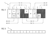
- FIGS. 2 and 3 show a zone plan Z of the winding arrangement of in FIG. 1 partially illustrated main element 400.
- the zone plan Z is according to FIG. 3 from six identical sub-zone plans S, which are arranged one behind the other and each represent nine slots 1 to 9.
- FIG. 2 shows a sub-zone map S.
- the crosses and circles in the sub-zone map S indicate the directions in which the grooves 1 to 9 along the winding strands 100, 200, 300 of the turns of the associated coils 101, 102, 201, 202, 301, 302 be traversed, wherein a cross indicating a pointing in the plane of the direction and a circle indicates a pointing out of the plane of the direction.
- FIG. 4 shows one in the FIGS. 2 and 3 illustrated zoning plan Z corresponding winding diagram of the winding arrangement of in FIG. 1 Shown are also an electrical interconnection of the coils 101, 102, 201, 202, 301, 302 and three outer conductors 110, 210, 310, which are each connected to one of the winding strands 100, 200, 300.
- Each first coil 101, 201, 301 of each winding strand 100, 200, 300 passes through a pair of grooves of two first grooves 1, 3, 4, 6, 7, 9, between which exactly two second grooves 2, 5, 8, through which a second coil 102, 202, 302 of the same winding strand 100, 200, 300 runs, and exactly two further first grooves 1, 3, 4, 6, 7, 9 are located.
- the two other first grooves 1, 3, 4, 6, 7, 9 are again between the two second grooves 2, 5, 8.
- By the two other first grooves 1, 3, 4, 6, 7, 9 in each case runs a first coil 101, 201, 301 of one of the other two winding strands 100, 200, 300, these two first coils 101, 201, 301 belonging to different winding strands 100, 200, 300.
- first grooves 1, 6 of each sub-zone plan S form a pair of grooves through which a first coil 101 of a first winding strand 100 extends.
- the first grooves 4, 9 of each sub-zone plan S form a pair of grooves through which a first coil 201 of a second winding strand 200 passes.
- a first groove 7 of each sub-zone plan S and a first groove 3 of the sub-zone plan S adjoining this sub-zone plan S on the right form a pair of grooves through which a first coil 301 of the third winding strand 300 runs.
- Each second coil 102 of the first winding strand 100 passes through the second grooves 2, 5 of a sub-zone plan S.
- Each second coil 202 of the second winding strand 200 passes through the second grooves 5, 8 of a sub-zone plan S.
- Each second coil 302 of the third winding strand 300 extends through the second groove 8 of a sub-zone plan S and the second groove 2 of the sub-zone plan S adjoining this sub-zone plan S on the right.
- each second coil 102 of the first winding strand 100 forms the lower layers of the two second grooves 2, 5, through which it passes.
- Each second coil 202 of the second winding strand 200 forms an upper layer of a second groove 5, through which it passes, and a lower layer of the other second groove 8, through which it passes.
- Each second coil 302 of the third winding strand 300 forms the upper layers of the two second grooves 2, 8 through which it passes (the lower layers of the second grooves 2, 5, 8 are in FIG FIG. 2 shown above the upper layers).
- the lower layer and the upper layer of each second groove 2, 5, 8 are separated from each other by an electrically insulating partition 550.
- All first coils 101, 201, 301 have a matching first number of turns and all second coils 102, 202, 302 have a matching second number of turns.
- the first number of turns is twice as large as the second number of turns in this first embodiment.
- all coils 101, 102, 201, 202, 301, 302 are made of a round wire of matching diameter. Therefore, each first coil 101, 201, 301 is twice as large as a second coil 102, 202, 302.
- all the grooves 1 to 9 are formed the same.
- the second coils 102, 202, 302 and the partition walls 550 are dimensioned such that the volumes of the second grooves 2, 5, 8 are filled by the second coils 102, 202, 302 extending through them and by the partition walls 550, respectively. Therefore, in the first grooves 1, 3, 4, 6, 7, 9, 500 voids 500 are formed due to the absence of partition walls 550. These voids 500 are filled by a stabilizing mass, preferably an epoxy resin, around the first coils 101, 201, 301 in the first grooves 1, 3, 4, 6, 7, 9 to stabilize.
- a stabilizing mass preferably an epoxy resin
- FIG. 5 shows a second embodiment of a main element 400.
- This embodiment differs from that based on the FIGS. 1 to 4 described only in that the first coils 101, 201, 301 each have a number of turns, which is more than twice as large as the number of turns of the second coil 102, 202, 302 and is dimensioned such that the first coil 101, 201 , 301 each completely fill a first groove 1, 3, 4, 6, 7, 9.
- the in FIG. 1 shown voids 550 in the first grooves 1, 3, 4, 6, 7, 9 and are replaced by additional turns of the first coil 101, 201, 301.
- the first coils 101, 201, 301 in the first grooves 1, 3, 4, 6, 7, 9 advantageously stabilized without an additional stabilization mass.
- the additional windings of the first coils 101, 201, 301 bring about improvements compared with the first exemplary embodiment, which are described below with reference to FIGS. 6 to 8 to be discribed.
- FIG. 6 shows in a diagram a winding factor spectrum of a winding factor ⁇ of a stator space field of in FIG. 1 shown first embodiment for space waves of different ordinal numbers N.
- FIG. 7 shows analogously to FIG. 6 a winding factor spectrum of a winding factor ⁇ of the stator space field of FIG. 5 illustrated second embodiment for space waves of different ordinal numbers N.
- the comparison with FIG. 6 shows that the second embodiment is slightly improved in terms of the winding factor spectrum over the first embodiment.
- FIG. 8 shows normalized copper losses C of the winding arrangements of FIGS FIGS. 1 and 5 illustrated embodiments in response to a normalized speed n.
- a first copper loss curve C1 shows the copper losses C of in FIG. 1 shown first embodiment
- a second copper loss curve C2 shows the copper losses C of in FIG. 5 illustrated second embodiment.
- the winding arrangements of both embodiments have an asymmetry due to the distribution of the first coils 101, 201, 301, which as a result of the slot scattering effect can cause asymmetrical phase currents in the winding strands 100, 200, 300.
- FIG. 8 shows that this current asymmetry in the second embodiment is less than in the first embodiment. This too is a consequence and advantageous effect of the additional turns of the first coils 101, 201, 301 of the second embodiment.
- the winding arrangements of both embodiments are each made by first all coils 101, 102 of the first winding strand 100 are simultaneously drawn into the respectively associated grooves 1, 2, 5, 6. Thereafter, partitions 550 are inserted into the second grooves 2, 5, through which a second coil 102 of the first winding strand 100 extends. Subsequently, all the coils 201, 202 of the second winding strand 200 are simultaneously drawn into the respectively associated grooves 4, 5, 8, 9. Thereafter, dividing walls 550 are introduced into the second grooves 8, which do not yet have partitions 550. Subsequently, all the coils 301, 302 of the third winding strand 300 are simultaneously drawn into the respectively associated grooves 2, 3, 7, 8.
- the stabilization mass is introduced into the voids 500 of the first grooves 1, 3, 4, 6, 7, 9.
- This manufacturing method is made possible by the above-described distribution of first coils 101, 201, 301 and second coils 102, 202, 302 on first grooves 1, 3, 4, 6, 7, 9 and second grooves 2, 5, 8.
- zone plan Z consists of the same sub-zone plans S each with nine grooves 1 to 9, the basis of the FIGS. 1 to 5
- embodiments described above are modified in an obvious way to further embodiments of main elements 400 with a number of grooves, which is an arbitrary multiple of nine.
Landscapes
- Engineering & Computer Science (AREA)
- Power Engineering (AREA)
- Manufacturing & Machinery (AREA)
- Windings For Motors And Generators (AREA)
- Manufacture Of Motors, Generators (AREA)
Priority Applications (5)
| Application Number | Priority Date | Filing Date | Title |
|---|---|---|---|
| EP14154478.3A EP2905875A1 (fr) | 2014-02-10 | 2014-02-10 | Élément principal d'une machine électrique |
| EP15702985.1A EP3084931A2 (fr) | 2014-02-10 | 2015-01-21 | Élément principal d'un moteur électrique |
| CN201580007770.1A CN106030994B (zh) | 2014-02-10 | 2015-01-21 | 电机的主部件 |
| US15/117,617 US9667103B2 (en) | 2014-02-10 | 2015-01-21 | Main element of an electric machine |
| PCT/EP2015/051097 WO2015117822A2 (fr) | 2014-02-10 | 2015-01-21 | Élément principal d'un moteur électrique |
Applications Claiming Priority (1)
| Application Number | Priority Date | Filing Date | Title |
|---|---|---|---|
| EP14154478.3A EP2905875A1 (fr) | 2014-02-10 | 2014-02-10 | Élément principal d'une machine électrique |
Publications (1)
| Publication Number | Publication Date |
|---|---|
| EP2905875A1 true EP2905875A1 (fr) | 2015-08-12 |
Family
ID=50068929
Family Applications (2)
| Application Number | Title | Priority Date | Filing Date |
|---|---|---|---|
| EP14154478.3A Withdrawn EP2905875A1 (fr) | 2014-02-10 | 2014-02-10 | Élément principal d'une machine électrique |
| EP15702985.1A Withdrawn EP3084931A2 (fr) | 2014-02-10 | 2015-01-21 | Élément principal d'un moteur électrique |
Family Applications After (1)
| Application Number | Title | Priority Date | Filing Date |
|---|---|---|---|
| EP15702985.1A Withdrawn EP3084931A2 (fr) | 2014-02-10 | 2015-01-21 | Élément principal d'un moteur électrique |
Country Status (4)
| Country | Link |
|---|---|
| US (1) | US9667103B2 (fr) |
| EP (2) | EP2905875A1 (fr) |
| CN (1) | CN106030994B (fr) |
| WO (1) | WO2015117822A2 (fr) |
Families Citing this family (2)
| Publication number | Priority date | Publication date | Assignee | Title |
|---|---|---|---|---|
| US20180129102A1 (en) * | 2015-04-06 | 2018-05-10 | Sharp Kabushiki Kaisha | Liquid crystal display device and method of producing liquid crystal display device |
| CN108649756A (zh) * | 2018-05-14 | 2018-10-12 | 雷勃电气(无锡)有限公司 | 一种适用于机械嵌线的低谐波绕组方法 |
Citations (4)
| Publication number | Priority date | Publication date | Assignee | Title |
|---|---|---|---|---|
| FR1182348A (fr) * | 1956-07-13 | 1959-06-24 | Thomson Houston Comp Francaise | Perfectionnements aux moteurs polyphasés à induction |
| EP1860757A1 (fr) * | 2006-05-23 | 2007-11-28 | Siemens Aktiengesellschaft | Machine électrique avec circuit de fraction d'enroulement |
| GB2463767A (en) * | 2008-09-30 | 2010-03-31 | Switched Reluctance Drives Ltd | Slot wedge for additionally engaging core end surface |
| US20120043846A1 (en) * | 2010-08-23 | 2012-02-23 | Emerson Electric Co | Motor with impedance balanced winding |
Family Cites Families (7)
| Publication number | Priority date | Publication date | Assignee | Title |
|---|---|---|---|---|
| GB1303243A (fr) | 1969-03-24 | 1973-01-17 | ||
| JPS54156102A (en) * | 1978-05-30 | 1979-12-08 | Matsushita Electric Ind Co Ltd | Method and machine of manufacturing stators of electrical machines |
| US4217690A (en) | 1978-06-23 | 1980-08-19 | Rapidsyn Co. | Method of assembly for electric motor stators |
| US5300846A (en) | 1992-10-08 | 1994-04-05 | Otis Elevator Company | Lamination support for a linear motor |
| GB2283133B (en) * | 1993-10-20 | 1998-04-15 | Gen Electric | Dynamoelectric machine and method for manufacturing same |
| JP2001025197A (ja) | 1999-07-06 | 2001-01-26 | Nissan Motor Co Ltd | 電動機のステータ |
| FR2896350B1 (fr) * | 2006-01-16 | 2008-02-29 | Valeo Equip Electr Moteur | Procede pour realiser le bobinage d'un stator de machine electrique tournante, et stator obtenu par ce procede |
-
2014
- 2014-02-10 EP EP14154478.3A patent/EP2905875A1/fr not_active Withdrawn
-
2015
- 2015-01-21 US US15/117,617 patent/US9667103B2/en active Active
- 2015-01-21 EP EP15702985.1A patent/EP3084931A2/fr not_active Withdrawn
- 2015-01-21 WO PCT/EP2015/051097 patent/WO2015117822A2/fr active Application Filing
- 2015-01-21 CN CN201580007770.1A patent/CN106030994B/zh active Active
Patent Citations (4)
| Publication number | Priority date | Publication date | Assignee | Title |
|---|---|---|---|---|
| FR1182348A (fr) * | 1956-07-13 | 1959-06-24 | Thomson Houston Comp Francaise | Perfectionnements aux moteurs polyphasés à induction |
| EP1860757A1 (fr) * | 2006-05-23 | 2007-11-28 | Siemens Aktiengesellschaft | Machine électrique avec circuit de fraction d'enroulement |
| GB2463767A (en) * | 2008-09-30 | 2010-03-31 | Switched Reluctance Drives Ltd | Slot wedge for additionally engaging core end surface |
| US20120043846A1 (en) * | 2010-08-23 | 2012-02-23 | Emerson Electric Co | Motor with impedance balanced winding |
Also Published As
| Publication number | Publication date |
|---|---|
| WO2015117822A2 (fr) | 2015-08-13 |
| US9667103B2 (en) | 2017-05-30 |
| CN106030994B (zh) | 2018-10-23 |
| US20160359381A1 (en) | 2016-12-08 |
| EP3084931A2 (fr) | 2016-10-26 |
| CN106030994A (zh) | 2016-10-12 |
| WO2015117822A3 (fr) | 2015-12-30 |
Similar Documents
| Publication | Publication Date | Title |
|---|---|---|
| EP3542446B1 (fr) | Bobine à enroulement ondulé pour un noyau feuilleté de stator d'une machine électrique | |
| DE102014111803A1 (de) | Verteilte kaskadierte Wicklung für elektrische Maschinen | |
| DE102014223202A1 (de) | Wellenwicklung, Stator und elektrische Maschine | |
| DE102016111212B4 (de) | Motor mit 8-förmigen verbundenen Spulen und Verfahren zur Herstellung Desselben | |
| DE102005019271A1 (de) | Statorspule mit konzentrierter Wicklung für eine rotierende elektrische Maschine | |
| DE112017003789T5 (de) | Elektrische Maschine mit einem Stator, der phasenverschobene Wicklungen hat | |
| DE102005018777A1 (de) | Statorspule mit konzentrierter Wicklung für eine rotierende elektrische Maschine | |
| DE2110126A1 (de) | Verdrillter Gitterstab fur elek tnsche Maschinen | |
| DE102020129807A1 (de) | Stator für elektrische maschine mit leitern mit unterschiedlichen querschnittformen | |
| DE102015222367A1 (de) | Wellenwicklung mit Wickelschema zur Verringerung der Spannungsdifferenzen in einer Statornut einer elektrischen Maschine | |
| DE202017107387U1 (de) | Multi-Zahnspulenwicklung für eine 2-strängige Drehfeldmaschine | |
| DE112021001268T5 (de) | Stator mit wellenförmiger spulenstruktur, damit ausgerüsteter dreiphasiger wechselstrommotor und verfahren zur herstellung des stators | |
| EP3878078A1 (fr) | Machine électrique, véhicule à moteur et procédé pour réaliser un bobinage pour une machine electrique | |
| DE202017107388U1 (de) | Multi-Zahnspulenwicklung für eine 3-strängige Drehfeldmaschine | |
| DE102022108615A1 (de) | Rautenspulen-stator mit parallelen pfaden und ausgeglichener wicklungsanordnung | |
| DE102012218508A1 (de) | Mehradrige Stableiter für elektrische Maschinen | |
| DE102021132259A1 (de) | Statorwicklungsanordnung mit mehreren parallelen Pfaden | |
| EP0994551B1 (fr) | Machine élèctrique polyphasée et sa fabrication | |
| DE102012218506A1 (de) | Stableiterformen für elektrische Maschinen | |
| EP2905875A1 (fr) | Élément principal d'une machine électrique | |
| DE102012206684A1 (de) | Elektrische Maschine mit Wellenwicklung und parallelen Stromzweigen | |
| WO2019110523A1 (fr) | Enroulement de bobine dentée multiple pour machine à champ magnétique rotatif triphasée | |
| EP3218993B1 (fr) | Stator d'une machine électrique | |
| DE69401637T2 (de) | Verbesserten Ständer für eine zweiphasige elektrische Maschine | |
| WO2016096246A1 (fr) | Ensemble d'enroulement et machine électrique avec ledit ensemble d'enroulement |
Legal Events
| Date | Code | Title | Description |
|---|---|---|---|
| PUAI | Public reference made under article 153(3) epc to a published international application that has entered the european phase |
Free format text: ORIGINAL CODE: 0009012 |
|
| AK | Designated contracting states |
Kind code of ref document: A1 Designated state(s): AL AT BE BG CH CY CZ DE DK EE ES FI FR GB GR HR HU IE IS IT LI LT LU LV MC MK MT NL NO PL PT RO RS SE SI SK SM TR |
|
| AX | Request for extension of the european patent |
Extension state: BA ME |
|
| STAA | Information on the status of an ep patent application or granted ep patent |
Free format text: STATUS: THE APPLICATION IS DEEMED TO BE WITHDRAWN |
|
| 18D | Application deemed to be withdrawn |
Effective date: 20160213 |