EP2905860A1 - Power distribution management device, power distribution management method, and power distribution management program - Google Patents
Power distribution management device, power distribution management method, and power distribution management program Download PDFInfo
- Publication number
- EP2905860A1 EP2905860A1 EP12886058.2A EP12886058A EP2905860A1 EP 2905860 A1 EP2905860 A1 EP 2905860A1 EP 12886058 A EP12886058 A EP 12886058A EP 2905860 A1 EP2905860 A1 EP 2905860A1
- Authority
- EP
- European Patent Office
- Prior art keywords
- facility
- power distribution
- installation
- combination
- search
- Prior art date
- Legal status (The legal status is an assumption and is not a legal conclusion. Google has not performed a legal analysis and makes no representation as to the accuracy of the status listed.)
- Granted
Links
Images







Classifications
-
- H—ELECTRICITY
- H02—GENERATION; CONVERSION OR DISTRIBUTION OF ELECTRIC POWER
- H02J—ELECTRIC POWER NETWORKS; CIRCUIT ARRANGEMENTS OR SYSTEMS FOR SUPPLYING OR DISTRIBUTING ELECTRIC POWER; SYSTEMS FOR STORING ELECTRIC ENERGY
- H02J13/00—Circuit arrangements for providing remote monitoring or remote control of equipment in a power distribution network
- H02J13/18—Circuit arrangements for providing remote monitoring or remote control of equipment in a power distribution network characterised by the remotely-controlled equipment, e.g. converters or transformers
- H02J13/333—Circuit arrangements for providing remote monitoring or remote control of equipment in a power distribution network characterised by the remotely-controlled equipment, e.g. converters or transformers the equipment forming part of substations
-
- G—PHYSICS
- G05—CONTROLLING; REGULATING
- G05B—CONTROL OR REGULATING SYSTEMS IN GENERAL; FUNCTIONAL ELEMENTS OF SUCH SYSTEMS; MONITORING OR TESTING ARRANGEMENTS FOR SUCH SYSTEMS OR ELEMENTS
- G05B15/00—Systems controlled by a computer
- G05B15/02—Systems controlled by a computer electric
-
- H—ELECTRICITY
- H02—GENERATION; CONVERSION OR DISTRIBUTION OF ELECTRIC POWER
- H02J—ELECTRIC POWER NETWORKS; CIRCUIT ARRANGEMENTS OR SYSTEMS FOR SUPPLYING OR DISTRIBUTING ELECTRIC POWER; SYSTEMS FOR STORING ELECTRIC ENERGY
- H02J13/00—Circuit arrangements for providing remote monitoring or remote control of equipment in a power distribution network
- H02J13/10—Circuit arrangements for providing remote monitoring or remote control of equipment in a power distribution network characterised by displaying of information or by user interaction, e.g. supervisory control and data acquisition [SCADA] systems
-
- H—ELECTRICITY
- H02—GENERATION; CONVERSION OR DISTRIBUTION OF ELECTRIC POWER
- H02J—ELECTRIC POWER NETWORKS; CIRCUIT ARRANGEMENTS OR SYSTEMS FOR SUPPLYING OR DISTRIBUTING ELECTRIC POWER; SYSTEMS FOR STORING ELECTRIC ENERGY
- H02J3/00—Circuit arrangements for AC mains or AC distribution networks
-
- H—ELECTRICITY
- H02—GENERATION; CONVERSION OR DISTRIBUTION OF ELECTRIC POWER
- H02J—ELECTRIC POWER NETWORKS; CIRCUIT ARRANGEMENTS OR SYSTEMS FOR SUPPLYING OR DISTRIBUTING ELECTRIC POWER; SYSTEMS FOR STORING ELECTRIC ENERGY
- H02J2103/00—Details of circuit arrangements for mains or AC distribution networks
- H02J2103/30—Simulating, planning, modelling, reliability check or computer assisted design [CAD] of electric power networks
- H02J2103/35—Grid-level management of power transmission or distribution systems, e.g. load flow analysis or active network management
-
- Y—GENERAL TAGGING OF NEW TECHNOLOGICAL DEVELOPMENTS; GENERAL TAGGING OF CROSS-SECTIONAL TECHNOLOGIES SPANNING OVER SEVERAL SECTIONS OF THE IPC; TECHNICAL SUBJECTS COVERED BY FORMER USPC CROSS-REFERENCE ART COLLECTIONS [XRACs] AND DIGESTS
- Y02—TECHNOLOGIES OR APPLICATIONS FOR MITIGATION OR ADAPTATION AGAINST CLIMATE CHANGE
- Y02B—CLIMATE CHANGE MITIGATION TECHNOLOGIES RELATED TO BUILDINGS, e.g. HOUSING, HOUSE APPLIANCES OR RELATED END-USER APPLICATIONS
- Y02B70/00—Technologies for an efficient end-user side electric power management and consumption
- Y02B70/30—Systems integrating technologies related to power network operation and communication or information technologies for improving the carbon footprint of the management of residential or tertiary loads, i.e. smart grids as climate change mitigation technology in the buildings sector, including also the last stages of power distribution and the control, monitoring or operating management systems at local level
- Y02B70/3225—Demand response systems, e.g. load shedding, peak shaving
-
- Y—GENERAL TAGGING OF NEW TECHNOLOGICAL DEVELOPMENTS; GENERAL TAGGING OF CROSS-SECTIONAL TECHNOLOGIES SPANNING OVER SEVERAL SECTIONS OF THE IPC; TECHNICAL SUBJECTS COVERED BY FORMER USPC CROSS-REFERENCE ART COLLECTIONS [XRACs] AND DIGESTS
- Y02—TECHNOLOGIES OR APPLICATIONS FOR MITIGATION OR ADAPTATION AGAINST CLIMATE CHANGE
- Y02B—CLIMATE CHANGE MITIGATION TECHNOLOGIES RELATED TO BUILDINGS, e.g. HOUSING, HOUSE APPLIANCES OR RELATED END-USER APPLICATIONS
- Y02B90/00—Enabling technologies or technologies with a potential or indirect contribution to GHG emissions mitigation
- Y02B90/20—Smart grids as enabling technology in buildings sector
-
- Y—GENERAL TAGGING OF NEW TECHNOLOGICAL DEVELOPMENTS; GENERAL TAGGING OF CROSS-SECTIONAL TECHNOLOGIES SPANNING OVER SEVERAL SECTIONS OF THE IPC; TECHNICAL SUBJECTS COVERED BY FORMER USPC CROSS-REFERENCE ART COLLECTIONS [XRACs] AND DIGESTS
- Y04—INFORMATION OR COMMUNICATION TECHNOLOGIES HAVING AN IMPACT ON OTHER TECHNOLOGY AREAS
- Y04S—SYSTEMS INTEGRATING TECHNOLOGIES RELATED TO POWER NETWORK OPERATION, COMMUNICATION OR INFORMATION TECHNOLOGIES FOR IMPROVING THE ELECTRICAL POWER GENERATION, TRANSMISSION, DISTRIBUTION, MANAGEMENT OR USAGE, i.e. SMART GRIDS
- Y04S10/00—Systems supporting electrical power generation, transmission or distribution
- Y04S10/40—Display of information, e.g. of data or controls
-
- Y—GENERAL TAGGING OF NEW TECHNOLOGICAL DEVELOPMENTS; GENERAL TAGGING OF CROSS-SECTIONAL TECHNOLOGIES SPANNING OVER SEVERAL SECTIONS OF THE IPC; TECHNICAL SUBJECTS COVERED BY FORMER USPC CROSS-REFERENCE ART COLLECTIONS [XRACs] AND DIGESTS
- Y04—INFORMATION OR COMMUNICATION TECHNOLOGIES HAVING AN IMPACT ON OTHER TECHNOLOGY AREAS
- Y04S—SYSTEMS INTEGRATING TECHNOLOGIES RELATED TO POWER NETWORK OPERATION, COMMUNICATION OR INFORMATION TECHNOLOGIES FOR IMPROVING THE ELECTRICAL POWER GENERATION, TRANSMISSION, DISTRIBUTION, MANAGEMENT OR USAGE, i.e. SMART GRIDS
- Y04S20/00—Management or operation of end-user stationary applications or the last stages of power distribution; Controlling, monitoring or operating thereof
-
- Y—GENERAL TAGGING OF NEW TECHNOLOGICAL DEVELOPMENTS; GENERAL TAGGING OF CROSS-SECTIONAL TECHNOLOGIES SPANNING OVER SEVERAL SECTIONS OF THE IPC; TECHNICAL SUBJECTS COVERED BY FORMER USPC CROSS-REFERENCE ART COLLECTIONS [XRACs] AND DIGESTS
- Y04—INFORMATION OR COMMUNICATION TECHNOLOGIES HAVING AN IMPACT ON OTHER TECHNOLOGY AREAS
- Y04S—SYSTEMS INTEGRATING TECHNOLOGIES RELATED TO POWER NETWORK OPERATION, COMMUNICATION OR INFORMATION TECHNOLOGIES FOR IMPROVING THE ELECTRICAL POWER GENERATION, TRANSMISSION, DISTRIBUTION, MANAGEMENT OR USAGE, i.e. SMART GRIDS
- Y04S20/00—Management or operation of end-user stationary applications or the last stages of power distribution; Controlling, monitoring or operating thereof
- Y04S20/20—End-user application control systems
- Y04S20/222—Demand response systems, e.g. load shedding, peak shaving
Definitions
- the present invention relates to a power distribution management apparatus, a power distribution management method, and a power distribution management program.
- a power distribution system has been known in which power sent from a power plant is converted in a power substation and supplied to a load facility of a customer such as a house or a factory.
- a wire connecting the power substation of an electric power provider and the load facility of the customer includes a high-voltage wire which distributes power equal to or more than a predetermined voltage and a low-voltage wire which distributes power converted by a pole transformer or the like.
- Standard voltages and allowable ranges to allow a deviation from the standard voltages are defined for the high-voltage wire and the low-voltage wire. For this reason, a voltage drop is calculated by dividing the power distribution system from the power substation to the load facility into a high-voltage system containing facilities such as the high-voltage wire and a switch and a low-voltage system containing facilities such as a low-voltage wire and a lead-in wire. Then, the voltage of the power distributed from the power substation is set such that a voltage before and after the voltage drop remains in the allowable ranges of the high-voltage system and the low-voltage system, or the voltage of the power flowing through the power distribution system is adjusted by switching the switch disposed in the high-voltage system.
- Patent Literature 1 Japanese Laid-open Patent Publication No. 10-70840
- the distributed power source is provided in the customer in some cases. In this case, it may occur that a reverse power flows from the distributed power source disposed in the customer to the power distribution system of the electric power provider. Therefore, in a case where the power flows bidirectionally between the power substation and the load facility, for example, it may be considered that the power at each facility contained in the low-voltage system is significantly changed by the reverse power flow.
- an object of the invention is to provide a power distribution management apparatus, a power distribution management method, and a power distribution management program which can ascertain the electrical connection of the power distribution system in a unit of facility.
- a power distribution management apparatus includes an electrical connection storage unit configured to store electrical connection information in which a combination of a plurality of junctions at which a plurality of facilities of a power distribution system are electrically connected to each other and a facility determined from the combination of the junctions are associated. Further, the power distribution management apparatus includes a search unit configured to search a facility corresponding to the combination while investigating an uninvestigated junction among the plurality of junctions contained in the combination starting from a predetermined junction with reference to the electrical connection information stored in the electrical connection storage unit. Further, the power distribution management apparatus includes an output unit configured to output a facility obtained from the combination of the junctions where the investigation is performed and a result of the search after the investigation and the search are performed.
- a power distribution management apparatus, a power distribution management method, and a power distribution management program according to the present application will be described with reference to the accompanying drawings. Further, embodiments herein do not limit the disclosed technology. Then, the respective embodiments can be implemented by appropriately combining each other in a scope where the processing contents do not conflict.
- FIG. 1 is a block diagram illustrating a functional configuration of a power distribution management apparatus according to a first embodiment.
- a power distribution management apparatus 10 illustrated in FIG. 1 provides a power distribution management service in which power distribution system information of facilities electrically connected to each other by a power distribution system between a power distribution substation of an electric power provider and a load facility of a customer is generated and output to a client terminal 30.
- a Web server may be mounted to perform the power distribution management process, or an outsourcing cloud may be mounted to provide the power distribution management service.
- a desired computer in which a power distribution management program provided as package software or online software is preinstalled or installed.
- the power distribution management apparatus 10 includes a communication I/F (interface) unit 11, a storage unit 13, and a controller 18. Further, besides the functional units illustrated in FIG. 1 , the power distribution management apparatus 10 may include various types of functional units (for example, functional units such as various types of input/output devices or an image pickup device) included in a well-known computer.
- a communication I/F (interface) unit 11 the power distribution management apparatus 10 may include various types of functional units (for example, functional units such as various types of input/output devices or an image pickup device) included in a well-known computer.
- the communication I/F unit 11 is an interface for performing communication control with respect to other apparatuses (for example, the client terminal 30).
- a network interface card such as a LAN (Local Area Network) card can be employed.
- the communication I/F unit 11 receives a browse request for the power distribution system information from the client terminal 30, or transmits the power distribution system information generated by the controller 18 to the client terminal 30.
- the storage unit 13 is a storage device which stores various types of programs such as an OS (Operating System) performed by the controller 18 and the power distribution management program.
- OS Operating System
- a semiconductor memory element such as flash memory and a storage device such as a hard disk and an optical disk are exemplified.
- the storage unit 13 is not limited to the above-mentioned storage devices, and may be RAM (Random Access Memory) or ROM (Read Only Memory).
- the storage unit 13 stores position information 14, facility information 15, electrical connection information 16, and power distribution system information 17 as an example of data used in the program executed by the controller 18. Further, besides the position information 14, the facility information 15, the electrical connection information 16, and the power distribution system information 17, other electronic data (for example, a history of power consumption in the load facility of the customer) may also be stored.
- the power distribution system is managed into three divisions as follows: a position management in which a location of the facility is managed, a facility management in which each facility and attribute information of the facility are managed, and an electrical connection management in which the facilities electrically connected to each other are managed.
- a position "location" at which a predetermined facility (for example, a power substation, a power pole, a transformer, and the like) is provided among the facilities forming the power distribution system is used as an entity.
- a facility "unit” linked at a position of one of the facilities forming the power distribution system and a facility “span” linked at two positions are used as an entity.
- a junction "node” at which the facilities are electrically connected to each other and a facility "branch” determined from a plurality of junctions are used as an entity.
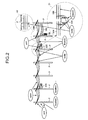
- FIG. 2 is a diagram illustrating an aspect of the entities.
- a non-installation facility such as a power pole P, and a pole transformer TR
- SS power distribution substation
- FIG. 2 is a diagram illustrating an aspect of the entities.
- a non-installation facility such as a power pole P, and a pole transformer TR
- SS power distribution substation
- a unit there are the power pole P, a switch SW, the pole transformer TR, and the like. Besides, the power distribution substation, an SVR (Step Voltage Regulator), and various types of meters (not illustrated) are also included in a category of the unit.
- SVR Step Voltage Regulator
- the span there is a wire (so-called "high-voltage wire”) WH which is laid on the high-voltage system between the power distribution substation and the pole transformer TR.
- a wire here-called "lead-in wire” laid on a section from the lead-in wire to the load facility, in addition to a wire (so-called "low-voltage wire”) WL laid on a section from the pole transformer TR to the lead-in wire in the low-voltage system between the pole transformer TR and the load facility of the customer.
- the wire W such as the high-voltage wire WH and the low-voltage wire WL, the number (for example, 3 or 2) of installation units of the power pole P can be collectively handled as one span.
- the node there are a junction between the high-voltage wire WH and the switch SW illustrated in an enlarged view 21 in FIG. 2 , a junction between the high-voltage wire WH and the pole transformer TR, and a junction between the pole transformer TR and the low-voltage wire WL. Besides, a connection point between the high-voltage wire WH21a and the high-voltage wire WH21b illustrated in an enlarged view 22 of FIG. 2 is also included in a category of the node.
- the high-voltage wire WH21a and the high-voltage wire WH21b are installed in the power pole P as a through pole, the high-voltage wire WH21a and the high-voltage wire WH21b are considered to be electrically connected, and a connection point between the high-voltage wires WH is considered as a virtual node.
- the branch there are the power pole P, the high-voltage wire WH, the switch SW, the pole transformer TR, the low-voltage wire WL, and the like illustrated in FIG. 2 .
- the power distribution substation, the lead-in wire, and the load facility are also included in a category of the branch.
- a facility positioned at the end point of the power distribution substation, the load facility, or the like may have one node.
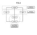
- FIG. 3 is a diagram illustrating an example of a mutual relation of the entities.
- the unit and the span have a relation with the location in that a common position therebetween is managed.
- the unit and the span have relation with the branch in that the facility is commonly managed.
- the node has relation with the location and the branch in that the junction is commonly managed.
- a location table 14a for managing the location is included in the position information 14.
- a unit table 15a for managing the unit and a span table 15b for managing the span are included in the facility information 15.
- a node table 16a for managing the node and a branch table 16b for managing the branch are included in the electrical connection information 16.
- a current node table 17a and a current branch table 17b are included in the power distribution system information 17.
- a table in which items such as a position ID (identifier), a position identification, a longitude, and a latitude are associated can be employed.
- the "position ID” indicates identification information for identifying a position where the facility is provided.
- the "position identification” indicates information for identifying a type of the position; for example, types of a power distribution substation (SS), a power pole (POLE), and a load facility (LOADL) are included.
- the information stored in the location table 14a for example, can acquire the position information of a specific facility such as the power substation, the power pole, and the transformer from another existing system (for example, an existing power distribution facility management system for managing the facilities in the power distribution system).
- FIG. 4 is a diagram illustrating an example of the location table 14a.
- a location of the position ID "SS0001" illustrated in FIG. 4 means that the power distribution substation is positioned at 128°08'48.66" east longitude and at 50°27'23.016" north latitude.
- various types of IDs are indexed by adding a string identifiable for the various types of facilities such as "SS” indicating the power distribution substation, "PO" indicating the power pole, and "LL” indicating the load facility to the head of a string forming the ID.
- the indexing of these various types of IDs is not limited to the indexing obtained by adding the string identifiable for the various types of facilities to the head of the string forming the ID, but may be assigned with values which can be uniquely recognized.
- the longitude and the latitude are exemplified as an item for specifying the position of the facility, but another item (for example, local coordinates, addresses, and the like) may be used.
- a table in which items such as a facility ID, a position ID, a type, and attribute information are associated can be employed.
- the "facility ID” indicates identification information for identifying the facility, and only the facility ID of the unit is stored in the unit table 15a.
- the "type” indicates a type of the unit; for example, the power pole (POLE), the switch (SW), the pole transformer (BANK), and the load facility (LOADL) are included.
- the "attribute information” indicates information relating to an attribute of the unit; for example, a serial number or performance of the unit is included (for example, in a case where the unit is a transformer, the capacity of the transformer is registered).
- the capacity of the transformer can be used to calculate a voltage drop when the electrical connection information of the facility of the current system is extracted. For example, in a case where the unit is the transformer, a resistance value, a reactance value, and a voltage ratio of the transformer are registered. Further, the information stored in the unit table 15a, for example, is acquired from another existing system (for example, a power-distribution facility management system), and the attribute information of the facility classified into the unit among the acquired attribute information of the facility is registered.
- another existing system for example, a power-distribution facility management system
- FIG. 5 is a diagram illustrating an example of the unit table 15a.
- the facility ID "PO0001P1" illustrated in FIG. 5 means that the unit is at a position corresponding to the position ID "PO0001" (that is, 128°08'41.76" east longitude and 50°27'23.021" north latitude illustrated in FIG. 4 ) and is the power pole.
- the facility ID "P0000101” illustrated in FIG. 5 means that the unit is at a position corresponding to the position ID "PO0001” (that is, 128°08'41.76” east longitude and 50°27'23.021” north latitude illustrated in FIG. 4 ) and is the switch.
- the unit is at a position corresponding to the position ID "PO0007" (that is, 128°08'34.30" east longitude and 50° 27' 27.844" in the example of FIG. 4 ), and is the pole transformer having a resistance value of "36800 ⁇ ", a reactance value of "31300 ⁇ ", and a voltage ratio of 1.
- the span table 15b a table in which items such as a facility ID, a position ID 1 , a position ID 2 , a type, and attribute information are associated can be employed.
- the "facility ID” herein also indicates the identification information for identifying the facility, and only the facility ID of the span is stored in the span table 15b.
- the "position ID 1 " indicates the position ID of one of two position IDs linked to the span
- the "position ID 2 " indicates the position ID of the other one of two position IDs linked to the span.
- the "type” indicates a type of the span; for example, the high-voltage wire, the low-voltage wire, and the lead-in wire are included.
- the "attribute information" indicates information relating to the attribute of the span; for example, a serial number of the span, a thickness, a material, a span size, a resistance value per unit (m), and a reactance value per unit (m) are included.
- the span size, the resistance value per unit, and the reactance value per unit can be used to calculate a voltage drop when the electrical connection information of the facility of the current system is extracted.
- the information stored in the span table 15b for example, is acquired from another existing system (for example, the power-distribution facility management system), and the attribute information of the facility classified into the span among the acquired attribute information of the facility is registered.
- FIG. 6 is a diagram illustrating an example of the span table 15b.
- the facility ID "SP0001" illustrated in FIG. 6 means that the span is a three-phase high-voltage wire installed in a section at positions corresponding to the position ID 1 "SS0001" and the position ID 2 "PO0001".
- the section corresponds to a section from 128°08'48.66" east longitude and 50°27'23.016" north latitude to 128°08'41.76" east longitude and 50°27'23.021" north latitude as described using FIG. 4 .
- the span size, the resistance value, and the reactance value of the facility ID "SP0001" mean “21 m”, “220 ⁇ /m”, and "150 ⁇ /m", respectively.
- the type illustrated in FIG. 6 is 3H, it means that the span is single-phase three high-voltage wires, and in a case where the type is 3L, it means that the span is single-phase three low-voltage wires.
- the type is a blank, it means that the span is a lead-in wire.
- the node table 16a As an aspect of the node table 16a, a table in which items such as a node ID and a position ID are associated can be employed.
- the "node ID" indicates the identification information for identifying the node.
- the information stored in the node table 16a is acquired from a power distribution automation system which performs a monitoring operation and a remote operation of the switch in another existing system (for example, the power-distribution facility management system and the power distribution system).
- the node is extracted from the facility information of the low-voltage system acquired from the power-distribution facility management system or the facility information of the high-voltage system acquired from the power distribution automation system, and then the node is registered in the node table 16a in association with a predetermined position.
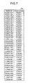
- FIG. 7 is a diagram illustrating an example of the node table 16a.
- the node ID "SS0001N01" illustrated in FIG. 7 means that the junction is at a position corresponding to the position ID "SS0001" (that is, 128°08'48.66" east longitude and 50°27'23.016" north latitude illustrated in FIG. 4 ).
- the node IDs "PO0001N01" and “PO0001N02" illustrated in FIG. 7 mean that the junctions are at the same position corresponding to the position ID "PO0001" (that is, 128°08'41.76" east longitude and 50°27'23.021" north latitude illustrated in FIG. 4 ).
- branch table 16b a table in which items such as a branch ID, a node ID 1 , a node ID 2 , a facility ID, and an open/close division are associated can be employed.
- the "branch ID” indicates the identification information for identifying the branch.
- the "node ID 1 " indicates one node ID of two node IDs of the branch
- the node ID 2 " indicates the other node ID of two node IDs of the branch.
- the branch positioned at the end point of the power distribution substation or the load facility may have any one node ID in the node ID 1 and the node ID 2 .
- the "facility ID” herein also indicates the identification information for identifying the facility, and the facility ID of any one of the unit and the span may be stored in the branch table 16b.
- the "open/close division” indicates the open/close state of a switch of the switch. In the open/close division, in a case where the branch is a switch, an "open state” or a “close state” of the switch is registered, but in a case where the branch is not the switch, a "blank" is registered.
- the information stored in the branch table 16b is acquired from another existing system (for example, the power-distribution facility management system and the power distribution automation system). For example, after the branch is extracted out of the facility information of the low-voltage system acquired from the power-distribution facility management system or the facility information of the high-voltage system acquired from the power distribution automation system, the extracted branch is registered in the branch table 16b in association with the node of the branch.
- another existing system for example, the power-distribution facility management system and the power distribution automation system.
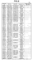
- FIG. 8 is a diagram illustrating an example of the branch table 16b.
- the branch ID "BR0001" illustrated in FIG. 8 means that the branch is the high-voltage wire of the facility ID "SP0001" defined by the node ID 1 "SS0001N01" and the node ID 2 "PO0001N01".
- the branch ID "BR0002" illustrated in FIG. 8 means that the branch is the switch of the facility ID "PO000101" defined by the node ID 1 "PO0001N01" and the node ID 2 "PO0001N02", and since the open/close division is set to "1", it means that the switch is in the close state. Further, in a case where the open/close division illustrated in FIG.
- the close state of the switch indicates a conductive state, and the open state indicates a nonconductive state.
- the controller 18 includes an internal memory for storing programs defining various processes and control data, and executes various processes using these programs and data. As illustrated in FIG. 1 , the controller 18 includes a search unit 18a, an association unit 18b, a detection unit 18c, and an output unit 18d.
- the search unit 18a is a processing unit which searches a branch corresponding to the subject combination with reference to the electrical connection information 16 while investigating an uninvestigated node among the nodes included in a node combination starting from a predetermined node.
- the search unit 18a activates the process in a case where a browse request of the power distribution system information is received through the client terminal 30 or in a case where a certain time period elapses after the previous process is executed.
- the search unit 18a searches a position ID of which the position type is the power distribution substation "SS" among the position IDs stored in the location table 14a.
- the search unit 18a registers the position ID of the power distribution substation SS investigated from the location table 14a in an investigation list stored in an internal memory (not illustrated). Besides the position ID of the power distribution substation SS as an investigation target, an uninvestigated node or an uninvestigated branch which is found out at the time of the investigation is registered in the investigation list whenever it is founded out.
- a case of searching the position ID of the power distribution substation SS from the location table 14a has been exemplified, but it may be configured to search a node ID starting with "SS" in a string among the node IDs stored in the node table 16a or the branch table 16b.
- the search unit 18a selects one position ID of the power distribution substation SS registered in the investigation list. Then, the search unit 18a searches a node corresponding to the position ID of the power distribution substation SS on which the selection is previously performed among the nodes stored in the node table 16a. Thereafter, the search unit 18a registers a record of the node searched from the node table 16a in the current node table 17a stored as the power distribution system information 17 in the storage unit 13. Furthermore, the search unit 18a registers the node searched from the node table 16a in the investigation list. Further, in a case where the power distribution substation SS includes a plurality of SS banks, even when the search is performed using one position ID, the records of the plurality of nodes are searched.
- the search unit 18a selects one node registered in the investigation list. Subsequently, the search unit 18a searches a record of the branch having a combination of the node IDs in which the previously-selected node is included (that is, a combination of the node ID 1 and the node ID 2 ) among the branches stored in the branch table 16b. Thereafter, the search unit 18a registers the record of the branch searched from the branch table 16b to the current branch table 17b stored as the power distribution system information 17 in the storage unit 13. Furthermore, the search unit 18a registers the branch searched from the branch table 16b in the investigation list. At this time, the one registered in the investigation list, for example, may be the branch ID or may be the facility ID.
- the search unit 18a selects one branch registered in the investigation list. Then, the search unit 18a searches the attribute information corresponding to the facility ID of the branch on which the selection is previously performed, from the span table 15b. At this time, in a case where the branch is a span, the attribute information can be searched from the span table 15b, but in a case where the branch is a unit, it is not possible to search the attribute information. For this reason, in a case where it is not possible to search the attribute information from the span table 15b, the search unit 18a searches the attribute information corresponding to the facility ID of the branch on which the selection is previously performed from the unit table 15a.
- the search unit 18a determines whether the subject branch is the switch. Then, in a case where the branch is a switch, the search unit 18a determines whether the switch of the switch is in the close state (that is, whether the open/close division is "1"). At this time, in a case where the switch of the switch is in the close state, since the switch is in a powered state (that is, the ON state), the search unit 18a searches the record of the other node from the node table 16a and then registers the searched node in the current node table 17a of the power distribution system information 17. Furthermore, the search unit 18a adds the other node to the investigation list as the uninvestigated node.
- the search unit 18a repeatedly performs the processes from the selection of the uninvestigated branch to the current process until all the branches registered in the investigation list are investigated. Thereafter, when all the branches registered in the investigation list are investigated, the search unit 18a repeatedly performs the processes from the selection of the uninvestigated node to the current process until all the nodes registered in the investigation list are investigated. Then, the search unit 18a repeatedly performs the processes from the selection of the position ID of the uninvestigated power distribution substation SS to the current process until all the position IDs of the power distribution substations SS registered in the investigation list are investigated.
- the position ID "SS0001" of which the position type is the power distribution substation "SS” is searched among the position IDs stored in the location table 14a illustrated in FIG. 4 .
- the position ID "SS0001" of the power distribution substation SS searched from the location table 14a is registered in the investigation list.
- the position ID "SS0001" is selected.
- the node ID "SS0001N01” corresponding to the position ID "SS0001" of the power distribution substation SS on which the selection is previously performed is searched among the nodes stored in the node table 16a illustrated in FIG. 7 . Subsequently, the record of the node ID "SS0001N01” searched from the node table 16a is registered in the current node table 17a. Furthermore, the node ID "SS0001N01” searched from the node table 16a is registered even in the investigation list. In this case, since only the node ID "SS0001N01" is registered in the investigation list, the node ID "SS0001N01" is selected.
- the branch of the facility ID "SP0001" having the combination of the node ID 1 "SS0001N01” and the node ID 2 "PO0001N01", in which the node ID "SS0001N01" on which the selection is previously performed, is found among the branches stored in the branch table 16b illustrated in FIG. 8 .
- the record of the branch of the facility ID "SP0001” searched from the branch table 16b is registered in the current branch table 17b.
- the facility ID "SP0001" searched from the branch table 16b is registered in the investigation list. In this case, since only the facility ID "SP0001" is registered in the investigation list, the facility ID "SP0001" is selected.
- the attribute information "span size 21 m, resistance R H1 , reactance X H1 " of the span corresponding to the facility ID "SP0001" on which the selection is previously performed is searched from the span table 15b illustrated in FIG. 6 . Further, herein, the description has been made about a case where the attribute information of the span is searched. However, in a case where the facility ID starts with a string other than "SP", the attribute information is not searched from the span table 15b, but the attribute information of the unit is searched from the unit table 15a illustrated in FIG. 5 .
- the other node ID "PO0001N01" paring with the node ID "SS0001N01” used in the investigation is set as a value in the combination of the node ID 1 "SS0001N01" and the node ID 2 "PO0001N01".
- the branch of the subject facility ID "SP0001” is a switch.
- a value of the open/close division is a blank, and the branch is not the switch.
- the record of the other node ID "PO0001N01” is searched from the node table 16a and then the record of the other node ID "PO0001N01" is registered in the current node table 17a of the power distribution system information 17. Furthermore, the other node ID "PO0001N01" is added to the investigation list as an uninvestigated node.
- the case where the other node ID is not a blank has been exemplified, but in a case where the other node ID is a blank, the investigation of the uninvestigated branch registered in the investigation list is performed. In addition, when the uninvestigated branch is not present, the investigation of the uninvestigated node is performed. Then, when the position ID of the uninvestigated power distribution substation SS is not present, the investigation is ended.
- the case where the branch is not a switch has been exemplified, but in a case where the branch is a switch, when the switch of the switch is not in the close state, the search of the other node ID and the addition of the other node to the investigation list are not performed.
- the association unit 18b is a processing unit which associates the facility (obtained from the combination of junctions where the investigation is performed and a result of the search) and the attribute information of a facility obtained as a result of the search among the attribute information contained in the facility information 15.
- the association unit 18b associates the record of the branch where the investigation is performed and the attribute information of the branch searched from the span table 15b or the unit table 15a.
- the association unit 18b registers the attribute information of the branch in association with the record of the branch used in the search of the span table 15b or the unit table 15a among the records stored in the current branch table 17b.
- the association unit 18b searches the position ID corresponding to the facility ID of the branch from the unit table 15a or the span table 15b and then further associates the position ID.
- FIG. 9 is a diagram illustrating an example of the current node table 17a.
- FIG. 10 is a diagram illustrating an example of the current branch table 17b.
- the current node table 17a and the current branch table 17b which are generated by using the respective tables illustrated in FIGS. 4 to 8 are illustrated starting from the node ID "SS0001N01".
- the power consumption (as an example of the attribute information) measured by a meter such as a smart meter is registered in the records of the nodes "LL0001N01", “LL0002N01", “LL0003N01”, “LL0004N01”, “LL0005N01”, “LL0006N01”, “LL0007N01”, and "LL0008N01” which are the junctions between the load facilities of the customers and the facilities of the power distribution system.
- the power consumption contains "effective power” which is consumed by the load facility and “reactive power” which is not consumed by the load facility. Among them, the reactive power is called delay reactive power.
- the power consumption (effective) and the power consumption (reactive) are referred in a case where the power of each node is calculated.
- the value of the open/close division registered in the branch table 16b is registered in a record in which the facility of the branch is a switch among the records of the current branch table 17b.
- the switch of which the open/close division is "1" has been exemplified, in a case where the open/close division of the switch is "0”, it means that the switch of the switch is in the open state and not in the energizing state.
- a reactance value X and a resistance value R are registered in the respective records of the current branch table 17b.
- the reactance value X and the resistance value R registered in the unit table 15a are registered as the attribute information without any change.
- the facility of the branch is a span
- a value obtained by multiplying the value of the span size by the reactance value per unit registered in the span table 15b is registered as the reactance value X
- a value obtained by multiplying the value of the span size by the resistance value per unit is registered as the resistance value R.
- the reactance value X and the resistance value R of these unit and span are referred in a case where a voltage at each node is calculated.
- connection phase item to which the transformer is connected is added in any one of the current node table 17a or the current branch table 17b, so that the calculation of the voltage can be accurately performed.
- connection phase 1 a first transformer connected to the wire on a pole
- connection phase 2 a second one
- connection phase 3 a third one
- a value of "A" can be registered
- the value of "B” can be registered
- a value of "C” can be registered.
- the detection unit 18c is a processing unit which compares the electrical connection information 16 with the power distribution system information 17 and detects a blackout facility. As an aspect, the detection unit 18c compares the record of the branch stored in the branch table 16b and the record of the branch stored in the current branch table 17b. At this time, in a case where the branch table 16b includes a record of the branch not matched with the current branch table 17b, the detection unit 18c detects the facility having the facility ID contained in the record of the subject branch as a blackout place. With this configuration, it is possible to automatically detect a facility which stops power transmission not by an accident or a failure.
- the output unit 18d is a processing unit which performs output control to the client terminal 30 using the power distribution system information 17.
- the output unit 18d selects an arbitrary facility ID designated by a predetermined facility ID (for example, the facility ID of the power distribution substation SS or an arbitrary facility ID designated from the client terminal 30) among the facility IDs contained in the current branch table 17b stored in the storage unit 13. Then, the output unit 18d sets a node ID closest to the power distribution substation SS among the combinations of the node IDs associated with the previously-selected facility IDs to a root of a hierarchical structure.
- a predetermined facility ID for example, the facility ID of the power distribution substation SS or an arbitrary facility ID designated from the client terminal 30
- the output unit 18d sets a node ID closest to the power distribution substation SS among the combinations of the node IDs associated with the previously-selected facility IDs to a root of a hierarchical structure.
- the output unit 18d assigns a low-level layer to the node as the number of nodes are increased from the root toward the facility ID of the load facility at the end terminal, and generates display data of a graph structure of the current system in which the facilities are disposed between the respective nodes from the root to the end terminal. Thereafter, the output unit 18d transmits the display data of the graph structure of the current system to the client terminal 30, and causes the client terminal 30 to display the graph structure of the current system. Further, the display data herein has been exemplified to be displayed in the client terminal 30, but it may be displayed in a display unit provided in the power distribution management apparatus 10.
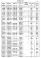
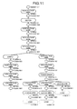
- FIGS. 11 and 12 are diagrams illustrating an example of the display data.
- FIGS. 11 and 12 illustrate the display data in a case where the current node table 17a illustrated in FIG. 9 and the current branch table 17b illustrated in FIG. 10 are expressed in the graph structure.
- the node of the node ID "SS0001N01" is set to the root (layer 1) of the hierarchical structure.
- routes from the root toward eight load facilities of the facility IDs "LL000101", "LL000201", “LL000301”, “LL000401”, “LL000501”, “LL000601", "LL000701", and "LL000801" at the end terminals are illustrated.
- the layers from the SS bank to the load facility of the facility ID "LL000801" are the lowest as 10 layers, and the layers from the SS bank to the load facilities of the facility IDs "LL000201", “LL000301” and “LL000401” are the deepest as 19 layers.
- the electrical connection in the power distribution system can be ascertained by subdividing the system in a unit of facility or a unit of junction between the facilities not in a rough unit such as the high-voltage system or the low-voltage system.
- the output unit 18d may generate the display data on a map in which the facilities such as the unit and the span are disposed.
- the output unit 18d acquires a position of the facility of the subject unit with reference to the position information 14 and the facility information 15.
- the output unit 18d acquires positions of both ends of the subject span.
- the output unit 18d may use the position of the unit and the positions of both ends of the span to output the display data which is disposed on the map where the units and spans are disposed.
- FIG. 13 is a diagram illustrating an example of the display data.
- the layers from the SS bank to the load facility of the facility ID "LL000801" are the lowest as 10 layers, and the layers from the SS bank to the load facilities of the facility IDs "LL000201", “LL000301” and "LL000401" are the deepest as 19 layers.
- the layers from the SS bank to the load facilities of the facility IDs "LL000201", “LL000301” and "LL000401" are the deepest as 19 layers.
- the display data illustrated in FIG. 13 similarly to the display data illustrated in FIGS.
- the power distribution system can be ascertained by subdividing the system in a unit of facility or a unit of junction between the facilities not in a rough unit such as the high-voltage system or the low-voltage system. Furthermore, in the display data illustrated in FIG. 13 , since the display positions of the unit and the span correspond to actual positions, it is possible to easily make a plan for maintenance or connection of the unit and the span. In addition, since geographical elements (for example, an infrastructure such as roads and railways, and land marks besides the facilities of the power distribution system) on the map can be compared with the eye, it is useful even for a spot inspection.
- geographical elements for example, an infrastructure such as roads and railways, and land marks besides the facilities of the power distribution system
- the output unit 18d may generate the display data attached with the attribute information in the vicinity of the facility which is disposed in a graph structure or a map.
- the output unit 18d may display the voltage ratio in the vicinity of the transformer, or may display resistance and reactance in the vicinity of the wire such as the high-voltage wire, the low-voltage wire, or the lead-in wire.
- the output unit 18d may calculate the voltage in each node using the attribute information (for example, the voltage ratio of the transformer, the resistance and reactance of the wire, or a history of the power consumption of each load facility stored in the storage unit 13) of the facility contained in the current branch table 17b. Furthermore, the output unit 18d may generate the display data attached with a voltage value of the current system to which the voltage value is added in the vicinity of the respective nodes disposed on the graph structure or the map.
- the attribute information for example, the voltage ratio of the transformer, the resistance and reactance of the wire, or a history of the power consumption of each load facility stored in the storage unit 13
- the output unit 18d may generate the display data attached with a voltage value of the current system to which the voltage value is added in the vicinity of the respective nodes disposed on the graph structure or the map.
- controller 18 may employ various integrated circuits or electronic circuits.
- some of the functional units of the controller 18 may be configured by other integrated circuits or electronic circuits.
- an ASIC Application Specific Integrated Circuit
- the electronic circuit a CPU (Central Processing Unit) or an MPU (Micro Processing Unit) may be used.
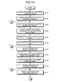
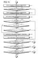
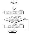
- FIGS. 14 to 16 are flowcharts illustrating a power distribution management process according to the first embodiment.
- the power distribution management process starts in a case where the browse request of the power distribution system information is received through the client terminal 30, or in a case where a certain time period elapses after the last process.
- the search unit 18a searches the position ID of which the position type is the power distribution substation "SS" among the position IDs stored in the location table 14a (Step S101). Then, the search unit 18a registers the position ID of the power distribution substation SS searched from the location table 14a to the investigation list (Step S102).
- the search unit 18a selects one position ID of the power distribution substation SS registered in the investigation list (Step S103). Then, the search unit 18a searches a node corresponding to the position ID of the power distribution substation SS to which the selection is previously performed among the nodes stored in the node table 16a (Step S104).
- the search unit 18a registers the record of the node searched from the node table 16a in the current node table 17a which is stored as the power distribution system information 17 in the storage unit 13 (Step S105). Furthermore, the search unit 18a registers the node searched from the node table 16a in the investigation list (Step S106).
- the search unit 18a selects one node registered in the investigation list (Step S107). Subsequently, the search unit 18a searches the record of the branch having a combination of the node IDs containing the node selected in Step S107 (that is, a combination of the node ID 1 and the node ID 2 ) among the branches stored in the branch table 16b (Step S108).
- the search unit 18a registers the record of the branch searched in Step S108 in the current branch table 17b (Step S109). Furthermore, the search unit 18a registers the branch searched in Step S108 in the investigation list (Step S110). Subsequently, the search unit 18a selects one branch registered in the investigation list (Step S111).
- the search unit 18a searches the attribute information corresponding to the facility ID of the branch selected in Step S111 from the span table 15b (Step S112). At this time, in a case where the attribute information is not possible to be searched from the span table 15b (that is, a case where the attribute information it not hit) (No in Step S113), the search unit 18a performs the following process.
- the search unit 18a searches the attribute information corresponding to the facility ID of the branch selected from the unit table 15a in Step S111 (Step S114). Further, in a case where the attribute information is possible to be searched from the span table 15b (Yes in Step S113), the procedure skips the process of Step S114 and moves to the process of Step S115.
- the association unit 18b registers the attribute information of the branch in association with the record of the subject branch used in the search of the span table 15b or the unit table 15a among the records stored in the current branch table 17b (Step S115).
- the search unit 18a determines whether the other node paring with the node investigated in Step S108 among the combinations of the nodes containing the branch searched in Step S108 is a blank (Step S116).
- the search unit 18a further determines whether the subject branch is a switch (Step S117). Then, in a case where the branch is a switch (Yes in Step S117), the search unit 18a further determines whether the switch of the switch is in the close state (that is, whether the switch is in the ON state) (Step S118).
- the search unit 18a searches the record of the other node from the node table 16a and then registers the other node in the current node table 17a of the power distribution system information 17 (Step S119). Furthermore, the search unit 18a adds the other node to the investigation list as the uninvestigated node (Step S120).
- the search unit 18a searches the record of the other node from the node table 16a and then registers the other node in the current node table 17a of the power distribution system information 17 (Step S119). Furthermore, the search unit 18a adds the other node to the investigation list as the uninvestigated node (Step S120).
- Step S121 the procedure proceeds to the process of Step S121.
- Step S121 determines whether all the branches registered in the investigation list are investigated. At this time, in a case where some of the branches registered in the investigation list are not investigated (No in Step S121), the uninvestigated branch is selected (Step S111) and then the processes from Step S112 to Step S121 are repeatedly performed.
- Step S121 the search unit 18a determines whether all the nodes registered in the investigation list are investigated. At this time, in a case where some of the nodes registered in the investigation list are not investigated (No in Step S122), the uninvestigated node is selected (Step S107) and then the processes from Step S108 to Step S121 are repeatedly performed.
- Step S122 the search unit 18a determines whether all the position IDs of the power distribution substations SS registered in the investigation list are investigated (Step S123). At this time, in a case where some of the position IDs of the power distribution substations SS registered in the investigation list are not investigated (No in Step S123), the position ID of the uninvestigated power distribution substation SS is selected (Step S103) and then the processes from Step S104 to Step S122 are repeatedly performed.
- the detection unit 18c compares the record of the branch stored in the branch table 16b and the record of the branch stored in the current branch table 17b (Step S124).
- the detection unit 18c detects the facility of the facility ID contained in the record of the subject branch as a blackout place (Step S126), and the process is ended.
- the branch table 16b has no record of the branch not matched with the current branch table 17b (No in Step S125)
- the process is ended without any action.
- the power distribution management apparatus 10 investigates the uninvestigated junction among the combinations of junctions to which the facilities of the power distribution system are electrically connected, and at the same time searches the facility determined from the combination of the uninvestigated junction and then outputs the connection information of the facility. Therefore, in the power distribution management apparatus 10 according to the embodiment, the electrical connection of the power distribution system can be ascertained in a unit of facility.
- a specific pattern of distribution and integration of the respective apparatuses is not limited to the pattern illustrated in the drawing, but some or all of them may be mechanically or physically distributed/integrated in an arbitrary unit according to various loads or usage conditions.
- a search unit 18a, an association unit 18b, a detection unit 18c, or an output unit 18d may be provided as an external apparatus of a power distribution management apparatus 10 to be connected through a network.
- the search unit 18a, the association unit 18b, the detection unit 18c, or the output unit 18d may be provided in an individual apparatus, and the function of the power distribution management apparatus 10 may be realized by connecting these apparatuses through the network to operate in cooperation with each other.
- FIG. 17 is a diagram for describing an example of the computer which executes the power distribution management program according to the first embodiment and the second embodiment.
- a computer 100 includes an operation unit 110a, a speaker 110b, a camera 110c, a display 120, and a communication unit 130.
- the computer 100 includes a CPU 150, ROM 160, an HDD 170, and RAM 180. These components 110 to 180 are connected to each other through a bus 140.
- a power distribution management program 170a which performs the same functions as the search unit 18a, the association unit 18b, the detection unit 18c, and the output unit 18d illustrated in the first embodiment is stored in the HDD 170 beforehand.
- the power distribution management program 170a may be appropriately integrated or divided similarly to the respective elements of the search unit 18a, the association unit 18b, the detection unit 18c, and the output unit 18d illustrated in FIG. 1 .
- all the data to be stored in the HDD 170 is not necessarily stored in the HDD 170, and only data used for the process may be stored in the HDD 170.
- the CPU 150 reads the power distribution management program 170a out of the HDD 170 and develops the program in the RAM 180. Therefore, as illustrated in FIG. 17 , the power distribution management program 170a functions as a power distribution management process 180a.
- the power distribution management process 180a develops various types of data read out of the HDD 170 in an area appropriately allocated for its own sake on the RAM 180, and performs various types of processes based on the various types of developed data. Further, the power distribution management process 180a includes the processes (for example, the processes illustrated in FIGS. 14 to 16 ) performed by the search unit 18a, the association unit 18b, the detection unit 18c, and the output unit 18d illustrated in FIG. 1 .
- all the respective processing units virtually realized on the CPU 150 are always not necessarily operated on the CPU 150, and only the processing units used for the process may be virtually realized.
- the power distribution management program 170a is not always stored in the HDD 170 or the ROM 160 from the beginning.
- the respective programs may be stored in a "portable physical medium" (what is called an FD, a CD-ROM, a DVD disk, a magnetooptical disk, an IC card, and the like) of a flexible disk inserted in the computer 100.
- the computer 100 may acquire the respective programs from the portable physical mediums and execute the programs.
- the respective programs are stored in another computer or a server apparatus connected to the computer 100 through a public line, the Internet, a LAN, a WAN, and the like, and the computer 100 may acquire and execute these programs.
Landscapes
- Engineering & Computer Science (AREA)
- Power Engineering (AREA)
- General Engineering & Computer Science (AREA)
- Physics & Mathematics (AREA)
- General Physics & Mathematics (AREA)
- Automation & Control Theory (AREA)
- Remote Monitoring And Control Of Power-Distribution Networks (AREA)
- Supply And Distribution Of Alternating Current (AREA)
Abstract
Description
- The present invention relates to a power distribution management apparatus, a power distribution management method, and a power distribution management program.
- A power distribution system has been known in which power sent from a power plant is converted in a power substation and supplied to a load facility of a customer such as a house or a factory. A wire connecting the power substation of an electric power provider and the load facility of the customer includes a high-voltage wire which distributes power equal to or more than a predetermined voltage and a low-voltage wire which distributes power converted by a pole transformer or the like.
- Standard voltages and allowable ranges to allow a deviation from the standard voltages are defined for the high-voltage wire and the low-voltage wire. For this reason, a voltage drop is calculated by dividing the power distribution system from the power substation to the load facility into a high-voltage system containing facilities such as the high-voltage wire and a switch and a low-voltage system containing facilities such as a low-voltage wire and a lead-in wire. Then, the voltage of the power distributed from the power substation is set such that a voltage before and after the voltage drop remains in the allowable ranges of the high-voltage system and the low-voltage system, or the voltage of the power flowing through the power distribution system is adjusted by switching the switch disposed in the high-voltage system.
- Patent Literature 1: Japanese Laid-open Patent Publication No.
10-70840 - By the way, as a distributed power source such as photovoltaic power generation comes into wide use, the distributed power source is provided in the customer in some cases. In this case, it may occur that a reverse power flows from the distributed power source disposed in the customer to the power distribution system of the electric power provider. Therefore, in a case where the power flows bidirectionally between the power substation and the load facility, for example, it may be considered that the power at each facility contained in the low-voltage system is significantly changed by the reverse power flow.
- However, in the related technology described above, there is a problem in that electrical connection of the power distribution system can be ascertained only in a rough unit of the high-voltage system and the low-voltage system. Therefore, in the related art described above, there is a concern that the abnormal situation is overlooked in a case where the power of the voltage exceeding the allowable range flows in a unit smaller than the high-voltage system and the low-voltage system.
- According to an aspect, an object of the invention is to provide a power distribution management apparatus, a power distribution management method, and a power distribution management program which can ascertain the electrical connection of the power distribution system in a unit of facility.
- A power distribution management apparatus according to one aspect includes an electrical connection storage unit configured to store electrical connection information in which a combination of a plurality of junctions at which a plurality of facilities of a power distribution system are electrically connected to each other and a facility determined from the combination of the junctions are associated. Further, the power distribution management apparatus includes a search unit configured to search a facility corresponding to the combination while investigating an uninvestigated junction among the plurality of junctions contained in the combination starting from a predetermined junction with reference to the electrical connection information stored in the electrical connection storage unit. Further, the power distribution management apparatus includes an output unit configured to output a facility obtained from the combination of the junctions where the investigation is performed and a result of the search after the investigation and the search are performed.
- According to an embodiment, it is possible to ascertain electrical connection of a power distribution system in a unit of facility.
-
-
FIG. 1 is a block diagram illustrating a functional configuration of a power distribution management apparatus according to a first embodiment. -
FIG. 2 is a diagram illustrating an aspect of entities. -
FIG. 3 is a diagram illustrating an example of a mutual relation of the entities. -
FIG. 4 is a diagram illustrating an example of a location table. -
FIG. 5 is a diagram illustrating an example of a unit table. -
FIG. 6 is a diagram illustrating an example of a span table. -
FIG. 7 is a diagram illustrating an example of a node table. -
FIG. 8 is a diagram illustrating an example of a branch table. -
FIG. 9 is a diagram illustrating an example of a current node table. -
FIG. 10 is a diagram illustrating an example of a current branch table. -
FIG. 11 is a diagram (1) illustrating an example of display data. -
FIG. 12 is a diagram (2) illustrating an example of the display data. -
FIG. 13 is a diagram illustrating an example of the display data. -
FIG. 14 is a flowchart (1) illustrating a power distribution management process according to the first embodiment. -
FIG. 15 is a flowchart (2) illustrating the power distribution management process according to the first embodiment. -
FIG. 16 is a flowchart (3) illustrating the power distribution management process according to the first embodiment. -
FIG. 17 is a diagram for describing an example of a computer which executes a power distribution management program according to the first embodiment and a second embodiment. - A power distribution management apparatus, a power distribution management method, and a power distribution management program according to the present application will be described with reference to the accompanying drawings. Further, embodiments herein do not limit the disclosed technology. Then, the respective embodiments can be implemented by appropriately combining each other in a scope where the processing contents do not conflict.
-
FIG. 1 is a block diagram illustrating a functional configuration of a power distribution management apparatus according to a first embodiment. A powerdistribution management apparatus 10 illustrated inFIG. 1 provides a power distribution management service in which power distribution system information of facilities electrically connected to each other by a power distribution system between a power distribution substation of an electric power provider and a load facility of a customer is generated and output to aclient terminal 30. - As an aspect of such power
distribution management apparatus 10, a Web server may be mounted to perform the power distribution management process, or an outsourcing cloud may be mounted to provide the power distribution management service. As another aspect, there may be provided a desired computer in which a power distribution management program provided as package software or online software is preinstalled or installed. - As illustrated in
FIG. 1 , the powerdistribution management apparatus 10 includes a communication I/F (interface)unit 11, astorage unit 13, and acontroller 18. Further, besides the functional units illustrated inFIG. 1 , the powerdistribution management apparatus 10 may include various types of functional units (for example, functional units such as various types of input/output devices or an image pickup device) included in a well-known computer. - The communication I/
F unit 11 is an interface for performing communication control with respect to other apparatuses (for example, the client terminal 30). As an aspect of such communication I/F unit 11, a network interface card such as a LAN (Local Area Network) card can be employed. For example, the communication I/F unit 11 receives a browse request for the power distribution system information from theclient terminal 30, or transmits the power distribution system information generated by thecontroller 18 to theclient terminal 30. - The
storage unit 13 is a storage device which stores various types of programs such as an OS (Operating System) performed by thecontroller 18 and the power distribution management program. As an aspect of thestorage unit 13, a semiconductor memory element such as flash memory and a storage device such as a hard disk and an optical disk are exemplified. Further, thestorage unit 13 is not limited to the above-mentioned storage devices, and may be RAM (Random Access Memory) or ROM (Read Only Memory). - The
storage unit 13stores position information 14,facility information 15,electrical connection information 16, and powerdistribution system information 17 as an example of data used in the program executed by thecontroller 18. Further, besides theposition information 14, thefacility information 15, theelectrical connection information 16, and the powerdistribution system information 17, other electronic data (for example, a history of power consumption in the load facility of the customer) may also be stored. - Herein, in the power
distribution management apparatus 10 according to the embodiment, the power distribution system is managed into three divisions as follows: a position management in which a location of the facility is managed, a facility management in which each facility and attribute information of the facility are managed, and an electrical connection management in which the facilities electrically connected to each other are managed. - Among them, in the position management, a position "location" at which a predetermined facility (for example, a power substation, a power pole, a transformer, and the like) is provided among the facilities forming the power distribution system is used as an entity. In addition, in the facility management, a facility "unit" linked at a position of one of the facilities forming the power distribution system and a facility "span" linked at two positions are used as an entity. In addition, in the electrical connection management, a junction "node" at which the facilities are electrically connected to each other and a facility "branch" determined from a plurality of junctions are used as an entity.
-
FIG. 2 is a diagram illustrating an aspect of the entities. As illustrated inFIG. 2 , as an example of the location, for example, there is a position where a non-installation facility (such as a power pole P, and a pole transformer TR) not provided by installation is provided. Besides, a position of a power distribution substation (SS) (not illustrated) or a position of the transformer is also included in a category of the location. - As an example of a unit, there are the power pole P, a switch SW, the pole transformer TR, and the like. Besides, the power distribution substation, an SVR (Step Voltage Regulator), and various types of meters (not illustrated) are also included in a category of the unit.
- As an example of the span, there is a wire (so-called "high-voltage wire") WH which is laid on the high-voltage system between the power distribution substation and the pole transformer TR. As another example of the span, there is a wire (so-called "lead-in wire") laid on a section from the lead-in wire to the load facility, in addition to a wire (so-called "low-voltage wire") WL laid on a section from the pole transformer TR to the lead-in wire in the low-voltage system between the pole transformer TR and the load facility of the customer. Further, regarding the wire W such as the high-voltage wire WH and the low-voltage wire WL, the number (for example, 3 or 2) of installation units of the power pole P can be collectively handled as one span.
- As an example of the node, there are a junction between the high-voltage wire WH and the switch SW illustrated in an
enlarged view 21 inFIG. 2 , a junction between the high-voltage wire WH and the pole transformer TR, and a junction between the pole transformer TR and the low-voltage wire WL. Besides, a connection point between the high-voltage wire WH21a and the high-voltage wire WH21b illustrated in anenlarged view 22 ofFIG. 2 is also included in a category of the node. Specifically, even in a case where the high-voltage wire WH21a and the high-voltage wire WH21b are installed in the power pole P as a through pole, the high-voltage wire WH21a and the high-voltage wire WH21b are considered to be electrically connected, and a connection point between the high-voltage wires WH is considered as a virtual node. - As an example of the branch, there are the power pole P, the high-voltage wire WH, the switch SW, the pole transformer TR, the low-voltage wire WL, and the like illustrated in
FIG. 2 . Besides, the power distribution substation, the lead-in wire, and the load facility (not illustrated) are also included in a category of the branch. A facility positioned at the end point of the power distribution substation, the load facility, or the like may have one node. - The entities of the location, the unit, the span, the node, and the branch have relevance as illustrated in
FIG. 3. FIG. 3 is a diagram illustrating an example of a mutual relation of the entities. As illustrated inFIG. 3 , the unit and the span have a relation with the location in that a common position therebetween is managed. In addition, the unit and the span have relation with the branch in that the facility is commonly managed. Furthermore, the node has relation with the location and the branch in that the junction is commonly managed. - Returning to the description of
FIG. 1 , a location table 14a for managing the location is included in theposition information 14. In addition, a unit table 15a for managing the unit and a span table 15b for managing the span are included in thefacility information 15. Furthermore, a node table 16a for managing the node and a branch table 16b for managing the branch are included in theelectrical connection information 16. In addition, as to be described below, a current node table 17a and a current branch table 17b are included in the powerdistribution system information 17. - Among them, as an aspect of the location table 14a, a table in which items such as a position ID (identifier), a position identification, a longitude, and a latitude are associated can be employed. The "position ID" indicates identification information for identifying a position where the facility is provided. In addition, the "position identification" indicates information for identifying a type of the position; for example, types of a power distribution substation (SS), a power pole (POLE), and a load facility (LOADL) are included. Further, the information stored in the location table 14a, for example, can acquire the position information of a specific facility such as the power substation, the power pole, and the transformer from another existing system (for example, an existing power distribution facility management system for managing the facilities in the power distribution system).
-
FIG. 4 is a diagram illustrating an example of the location table 14a. For example, a location of the position ID "SS0001" illustrated inFIG. 4 means that the power distribution substation is positioned at 128°08'48.66" east longitude and at 50°27'23.016" north latitude. In addition, in the subsequent drawings ofFIG. 4 , various types of IDs are indexed by adding a string identifiable for the various types of facilities such as "SS" indicating the power distribution substation, "PO" indicating the power pole, and "LL" indicating the load facility to the head of a string forming the ID. The indexing of these various types of IDs is not limited to the indexing obtained by adding the string identifiable for the various types of facilities to the head of the string forming the ID, but may be assigned with values which can be uniquely recognized. Further, herein, the longitude and the latitude are exemplified as an item for specifying the position of the facility, but another item (for example, local coordinates, addresses, and the like) may be used. - As an aspect of the unit table 15a, a table in which items such as a facility ID, a position ID, a type, and attribute information are associated can be employed. The "facility ID" indicates identification information for identifying the facility, and only the facility ID of the unit is stored in the unit table 15a. In addition, the "type" indicates a type of the unit; for example, the power pole (POLE), the switch (SW), the pole transformer (BANK), and the load facility (LOADL) are included. In addition, the "attribute information" indicates information relating to an attribute of the unit; for example, a serial number or performance of the unit is included (for example, in a case where the unit is a transformer, the capacity of the transformer is registered). The capacity of the transformer can be used to calculate a voltage drop when the electrical connection information of the facility of the current system is extracted. For example, in a case where the unit is the transformer, a resistance value, a reactance value, and a voltage ratio of the transformer are registered. Further, the information stored in the unit table 15a, for example, is acquired from another existing system (for example, a power-distribution facility management system), and the attribute information of the facility classified into the unit among the acquired attribute information of the facility is registered.
-
FIG. 5 is a diagram illustrating an example of the unit table 15a. For example, the facility ID "PO0001P1" illustrated inFIG. 5 means that the unit is at a position corresponding to the position ID "PO0001" (that is, 128°08'41.76" east longitude and 50°27'23.021" north latitude illustrated inFIG. 4 ) and is the power pole. In addition, the facility ID "P0000101" illustrated inFIG. 5 means that the unit is at a position corresponding to the position ID "PO0001" (that is, 128°08'41.76" east longitude and 50°27'23.021" north latitude illustrated inFIG. 4 ) and is the switch. In addition, the facility ID "PO000701" illustrated inFIG. 5 means that the unit is at a position corresponding to the position ID "PO0007" (that is, 128°08'34.30" east longitude and 50° 27' 27.844" in the example ofFIG. 4 ), and is the pole transformer having a resistance value of "36800 Ω", a reactance value of "31300 Ω", and a voltage ratio of 1. - As an aspect of the span table 15b, a table in which items such as a facility ID, a position ID1, a position ID2, a type, and attribute information are associated can be employed. The "facility ID" herein also indicates the identification information for identifying the facility, and only the facility ID of the span is stored in the span table 15b. In addition, the "position ID1" indicates the position ID of one of two position IDs linked to the span, and the "position ID2" indicates the position ID of the other one of two position IDs linked to the span. In addition, the "type" indicates a type of the span; for example, the high-voltage wire, the low-voltage wire, and the lead-in wire are included. In addition, the "attribute information" indicates information relating to the attribute of the span; for example, a serial number of the span, a thickness, a material, a span size, a resistance value per unit (m), and a reactance value per unit (m) are included. The span size, the resistance value per unit, and the reactance value per unit can be used to calculate a voltage drop when the electrical connection information of the facility of the current system is extracted. Further, the information stored in the span table 15b, for example, is acquired from another existing system (for example, the power-distribution facility management system), and the attribute information of the facility classified into the span among the acquired attribute information of the facility is registered.
-
FIG. 6 is a diagram illustrating an example of the span table 15b. For example, the facility ID "SP0001" illustrated inFIG. 6 means that the span is a three-phase high-voltage wire installed in a section at positions corresponding to the position ID1 "SS0001" and the position ID2 "PO0001". The section corresponds to a section from 128°08'48.66" east longitude and 50°27'23.016" north latitude to 128°08'41.76" east longitude and 50°27'23.021" north latitude as described usingFIG. 4 . Furthermore, the span size, the resistance value, and the reactance value of the facility ID "SP0001" mean "21 m", "220 Ω/m", and "150 Ω/m", respectively. Further, in a case where the type illustrated inFIG. 6 is 3H, it means that the span is single-phase three high-voltage wires, and in a case where the type is 3L, it means that the span is single-phase three low-voltage wires. In addition, in a case where the type is a blank, it means that the span is a lead-in wire. - As an aspect of the node table 16a, a table in which items such as a node ID and a position ID are associated can be employed. The "node ID" indicates the identification information for identifying the node. Further, the information stored in the node table 16a is acquired from a power distribution automation system which performs a monitoring operation and a remote operation of the switch in another existing system (for example, the power-distribution facility management system and the power distribution system). For example, the node is extracted from the facility information of the low-voltage system acquired from the power-distribution facility management system or the facility information of the high-voltage system acquired from the power distribution automation system, and then the node is registered in the node table 16a in association with a predetermined position.
-
FIG. 7 is a diagram illustrating an example of the node table 16a. For example, the node ID "SS0001N01" illustrated inFIG. 7 means that the junction is at a position corresponding to the position ID "SS0001" (that is, 128°08'48.66" east longitude and 50°27'23.016" north latitude illustrated inFIG. 4 ). In addition, the node IDs "PO0001N01" and "PO0001N02" illustrated inFIG. 7 mean that the junctions are at the same position corresponding to the position ID "PO0001" (that is, 128°08'41.76" east longitude and 50°27'23.021" north latitude illustrated inFIG. 4 ). - As an aspect of the branch table 16b, a table in which items such as a branch ID, a node ID1, a node ID2, a facility ID, and an open/close division are associated can be employed. The "branch ID" indicates the identification information for identifying the branch. In addition, the "node ID1" indicates one node ID of two node IDs of the branch, and "the node ID2" indicates the other node ID of two node IDs of the branch. However, the branch positioned at the end point of the power distribution substation or the load facility may have any one node ID in the node ID1 and the node ID2. In addition, the "facility ID" herein also indicates the identification information for identifying the facility, and the facility ID of any one of the unit and the span may be stored in the branch table 16b. In addition, the "open/close division" indicates the open/close state of a switch of the switch. In the open/close division, in a case where the branch is a switch, an "open state" or a "close state" of the switch is registered, but in a case where the branch is not the switch, a "blank" is registered.
- Further, the information stored in the branch table 16b is acquired from another existing system (for example, the power-distribution facility management system and the power distribution automation system). For example, after the branch is extracted out of the facility information of the low-voltage system acquired from the power-distribution facility management system or the facility information of the high-voltage system acquired from the power distribution automation system, the extracted branch is registered in the branch table 16b in association with the node of the branch.
-
FIG. 8 is a diagram illustrating an example of the branch table 16b. For example, the branch ID "BR0001" illustrated inFIG. 8 means that the branch is the high-voltage wire of the facility ID "SP0001" defined by the node ID1 "SS0001N01" and the node ID2 "PO0001N01". In addition, the branch ID "BR0002" illustrated inFIG. 8 means that the branch is the switch of the facility ID "PO000101" defined by the node ID1 "PO0001N01" and the node ID2 "PO0001N02", and since the open/close division is set to "1", it means that the switch is in the close state. Further, in a case where the open/close division illustrated inFIG. 8 is set to "0", it means that the switch is in the open state, and in a case where the open/close division is set to a blank, it means that the facility is not the switch. The close state of the switch indicates a conductive state, and the open state indicates a nonconductive state. - The
controller 18 includes an internal memory for storing programs defining various processes and control data, and executes various processes using these programs and data. As illustrated inFIG. 1 , thecontroller 18 includes asearch unit 18a, anassociation unit 18b, adetection unit 18c, and anoutput unit 18d. - The
search unit 18a is a processing unit which searches a branch corresponding to the subject combination with reference to theelectrical connection information 16 while investigating an uninvestigated node among the nodes included in a node combination starting from a predetermined node. - As an aspect, the
search unit 18a activates the process in a case where a browse request of the power distribution system information is received through theclient terminal 30 or in a case where a certain time period elapses after the previous process is executed. First, thesearch unit 18a searches a position ID of which the position type is the power distribution substation "SS" among the position IDs stored in the location table 14a. Then, thesearch unit 18a registers the position ID of the power distribution substation SS investigated from the location table 14a in an investigation list stored in an internal memory (not illustrated). Besides the position ID of the power distribution substation SS as an investigation target, an uninvestigated node or an uninvestigated branch which is found out at the time of the investigation is registered in the investigation list whenever it is founded out. Further, herein, a case of searching the position ID of the power distribution substation SS from the location table 14a has been exemplified, but it may be configured to search a node ID starting with "SS" in a string among the node IDs stored in the node table 16a or the branch table 16b. - Subsequently, the
search unit 18a selects one position ID of the power distribution substation SS registered in the investigation list. Then, thesearch unit 18a searches a node corresponding to the position ID of the power distribution substation SS on which the selection is previously performed among the nodes stored in the node table 16a. Thereafter, thesearch unit 18a registers a record of the node searched from the node table 16a in the current node table 17a stored as the powerdistribution system information 17 in thestorage unit 13. Furthermore, thesearch unit 18a registers the node searched from the node table 16a in the investigation list. Further, in a case where the power distribution substation SS includes a plurality of SS banks, even when the search is performed using one position ID, the records of the plurality of nodes are searched. - Then, the
search unit 18a selects one node registered in the investigation list. Subsequently, thesearch unit 18a searches a record of the branch having a combination of the node IDs in which the previously-selected node is included (that is, a combination of the node ID1 and the node ID2) among the branches stored in the branch table 16b. Thereafter, thesearch unit 18a registers the record of the branch searched from the branch table 16b to the current branch table 17b stored as the powerdistribution system information 17 in thestorage unit 13. Furthermore, thesearch unit 18a registers the branch searched from the branch table 16b in the investigation list. At this time, the one registered in the investigation list, for example, may be the branch ID or may be the facility ID. - Subsequently, the
search unit 18a selects one branch registered in the investigation list. Then, thesearch unit 18a searches the attribute information corresponding to the facility ID of the branch on which the selection is previously performed, from the span table 15b. At this time, in a case where the branch is a span, the attribute information can be searched from the span table 15b, but in a case where the branch is a unit, it is not possible to search the attribute information. For this reason, in a case where it is not possible to search the attribute information from the span table 15b, thesearch unit 18a searches the attribute information corresponding to the facility ID of the branch on which the selection is previously performed from the unit table 15a. - Thereafter, in a case where the other node paring with the node used in the investigation among the combination of the nodes is not a blank, the
search unit 18a determines whether the subject branch is the switch. Then, in a case where the branch is a switch, thesearch unit 18a determines whether the switch of the switch is in the close state (that is, whether the open/close division is "1"). At this time, in a case where the switch of the switch is in the close state, since the switch is in a powered state (that is, the ON state), thesearch unit 18a searches the record of the other node from the node table 16a and then registers the searched node in the current node table 17a of the powerdistribution system information 17. Furthermore, thesearch unit 18a adds the other node to the investigation list as the uninvestigated node. - Then, the
search unit 18a repeatedly performs the processes from the selection of the uninvestigated branch to the current process until all the branches registered in the investigation list are investigated. Thereafter, when all the branches registered in the investigation list are investigated, thesearch unit 18a repeatedly performs the processes from the selection of the uninvestigated node to the current process until all the nodes registered in the investigation list are investigated. Then, thesearch unit 18a repeatedly performs the processes from the selection of the position ID of the uninvestigated power distribution substation SS to the current process until all the position IDs of the power distribution substations SS registered in the investigation list are investigated. - Herein, a searching process of the
search unit 18a will be specifically described using the respective tables ofFIGS. 4 to 8 . First, the position ID "SS0001" of which the position type is the power distribution substation "SS" is searched among the position IDs stored in the location table 14a illustrated inFIG. 4 . Then, the position ID "SS0001" of the power distribution substation SS searched from the location table 14a is registered in the investigation list. In this case, since only the position ID "SS0001" of the power distribution substation SS is registered in the investigation list, the position ID "SS0001" is selected. Then, the node ID "SS0001N01" corresponding to the position ID "SS0001" of the power distribution substation SS on which the selection is previously performed is searched among the nodes stored in the node table 16a illustrated inFIG. 7 . Subsequently, the record of the node ID "SS0001N01" searched from the node table 16a is registered in the current node table 17a. Furthermore, the node ID "SS0001N01" searched from the node table 16a is registered even in the investigation list. In this case, since only the node ID "SS0001N01" is registered in the investigation list, the node ID "SS0001N01" is selected. - Then, the branch of the facility ID "SP0001" having the combination of the node ID1 "SS0001N01" and the node ID2 "PO0001N01", in which the node ID "SS0001N01" on which the selection is previously performed, is found among the branches stored in the branch table 16b illustrated in
FIG. 8 . Thereafter, the record of the branch of the facility ID "SP0001" searched from the branch table 16b is registered in the current branch table 17b. Furthermore, the facility ID "SP0001" searched from the branch table 16b is registered in the investigation list. In this case, since only the facility ID "SP0001" is registered in the investigation list, the facility ID "SP0001" is selected. - Then, the attribute information "span size 21 m, resistance RH1, reactance XH1" of the span corresponding to the facility ID "SP0001" on which the selection is previously performed is searched from the span table 15b illustrated in
FIG. 6 . Further, herein, the description has been made about a case where the attribute information of the span is searched. However, in a case where the facility ID starts with a string other than "SP", the attribute information is not searched from the span table 15b, but the attribute information of the unit is searched from the unit table 15a illustrated inFIG. 5 . - From the attribute information "span size 21 m,
resistance 220 Ω/m,reactance 150 Ω/m" thus obtained, a resistance value of 4621 (220 × 21) Ω and a reactance value of 3150 (150 × 21) Ω are registered in the current branch table 17b in association with the record of the branch of the facility ID "SP0001" used in searching the span table 15b. - Thereafter, the other node ID "PO0001N01" paring with the node ID "SS0001N01" used in the investigation is set as a value in the combination of the node ID1 "SS0001N01" and the node ID2 "PO0001N01". In this way, since the other node ID is not a blank, it is determined whether the branch of the subject facility ID "SP0001" is a switch. Then, in the branch of the facility ID "SP0001", a value of the open/close division is a blank, and the branch is not the switch. Therefore, the record of the other node ID "PO0001N01" is searched from the node table 16a and then the record of the other node ID "PO0001N01" is registered in the current node table 17a of the power
distribution system information 17. Furthermore, the other node ID "PO0001N01" is added to the investigation list as an uninvestigated node. - In this way, at the time when the other node ID "PO0001N01" is registered in the investigation list as an uninvestigated node, the node ID other than the node ID "PO0001N01" is not registered. Therefore, the node ID "PO0001N01" is investigated and then the search is kept on.
- Further, herein, the case where the other node ID is not a blank has been exemplified, but in a case where the other node ID is a blank, the investigation of the uninvestigated branch registered in the investigation list is performed. In addition, when the uninvestigated branch is not present, the investigation of the uninvestigated node is performed. Then, when the position ID of the uninvestigated power distribution substation SS is not present, the investigation is ended. In addition, herein, the case where the branch is not a switch has been exemplified, but in a case where the branch is a switch, when the switch of the switch is not in the close state, the search of the other node ID and the addition of the other node to the investigation list are not performed. This is because in a case where the switch of the switch is in the open state, when the search of the other node ID and the addition of the other node to the investigation list are performed, another power distribution system which is not electrically connected is erroneously registered in the current node table 17a or the current branch table 17b.
- Returning to the description of
FIG. 1 , theassociation unit 18b is a processing unit which associates the facility (obtained from the combination of junctions where the investigation is performed and a result of the search) and the attribute information of a facility obtained as a result of the search among the attribute information contained in thefacility information 15. As an aspect, theassociation unit 18b associates the record of the branch where the investigation is performed and the attribute information of the branch searched from the span table 15b or the unit table 15a. For example, theassociation unit 18b registers the attribute information of the branch in association with the record of the branch used in the search of the span table 15b or the unit table 15a among the records stored in the current branch table 17b. At this time, theassociation unit 18b searches the position ID corresponding to the facility ID of the branch from the unit table 15a or the span table 15b and then further associates the position ID. - Therefore, as a result of associating the record of the branch and the attribute information of the branch in the current branch table 17b after the investigation is ended, it is possible to generate the power
distribution system information 17 in which the facilities of the current system electrically connected to each other and the attribute information of the current system are associated with each other. - Herein, the current node table 17a and the current branch table 17b will be described.
FIG. 9 is a diagram illustrating an example of the current node table 17a.FIG. 10 is a diagram illustrating an example of the current branch table 17b. InFIGS. 9 and10 , the current node table 17a and the current branch table 17b which are generated by using the respective tables illustrated inFIGS. 4 to 8 are illustrated starting from the node ID "SS0001N01". - As illustrated in
FIG. 9 , among the records of the current node table 17a, the power consumption (as an example of the attribute information) measured by a meter such as a smart meter is registered in the records of the nodes "LL0001N01", "LL0002N01", "LL0003N01", "LL0004N01", "LL0005N01", "LL0006N01", "LL0007N01", and "LL0008N01" which are the junctions between the load facilities of the customers and the facilities of the power distribution system. The power consumption contains "effective power" which is consumed by the load facility and "reactive power" which is not consumed by the load facility. Among them, the reactive power is called delay reactive power. The power consumption (effective) and the power consumption (reactive) are referred in a case where the power of each node is calculated. - As illustrated in
FIG. 10 , the value of the open/close division registered in the branch table 16b is registered in a record in which the facility of the branch is a switch among the records of the current branch table 17b. For example, since all the open/close divisions are registered with a value of "1" in the switch of the branch IDs "BR0002", "BR0006", and "BR0019", it means that the switches of the switches are in the close state and in the energizing state. InFIG. 10 , the switch of which the open/close division is "1" has been exemplified, in a case where the open/close division of the switch is "0", it means that the switch of the switch is in the open state and not in the energizing state. In addition, a reactance value X and a resistance value R (as an example of the attribute information) are registered in the respective records of the current branch table 17b. Among them, in a case where the facility of the branch is a unit (for example, the switch or the transformer), the reactance value X and the resistance value R registered in the unit table 15a are registered as the attribute information without any change. On the other hand, in a case where the facility of the branch is a span, a value obtained by multiplying the value of the span size by the reactance value per unit registered in the span table 15b is registered as the reactance value X, and a value obtained by multiplying the value of the span size by the resistance value per unit is registered as the resistance value R. The reactance value X and the resistance value R of these unit and span are referred in a case where a voltage at each node is calculated. - Further, herein, the power consumption (effective), the power consumption (reactive), the resistance value, and the reactance value have been exemplified as a parameter used for calculating the voltage, a connection phase item to which the transformer is connected is added in any one of the current node table 17a or the current branch table 17b, so that the calculation of the voltage can be accurately performed. For example, in a case where the wires are the single-phase three wires, a first transformer connected to the wire on a pole is referred to as "
connection phase 1", a second one is referred to as "connection phase 2", and a third one is referred to as "connection phase 3". Further, in a case where the transformer is connected to the first and second wires of the three wires, a value of "A" can be registered, in a case where the second and third wires are connected to the transformer, the value of "B" can be registered, and in a case where the first and third wires are connected to the transformer, a value of "C" can be registered. - The
detection unit 18c is a processing unit which compares theelectrical connection information 16 with the powerdistribution system information 17 and detects a blackout facility. As an aspect, thedetection unit 18c compares the record of the branch stored in the branch table 16b and the record of the branch stored in the current branch table 17b. At this time, in a case where the branch table 16b includes a record of the branch not matched with the current branch table 17b, thedetection unit 18c detects the facility having the facility ID contained in the record of the subject branch as a blackout place. With this configuration, it is possible to automatically detect a facility which stops power transmission not by an accident or a failure. - The
output unit 18d is a processing unit which performs output control to theclient terminal 30 using the powerdistribution system information 17. As an aspect, theoutput unit 18d selects an arbitrary facility ID designated by a predetermined facility ID (for example, the facility ID of the power distribution substation SS or an arbitrary facility ID designated from the client terminal 30) among the facility IDs contained in the current branch table 17b stored in thestorage unit 13. Then, theoutput unit 18d sets a node ID closest to the power distribution substation SS among the combinations of the node IDs associated with the previously-selected facility IDs to a root of a hierarchical structure. Then, theoutput unit 18d assigns a low-level layer to the node as the number of nodes are increased from the root toward the facility ID of the load facility at the end terminal, and generates display data of a graph structure of the current system in which the facilities are disposed between the respective nodes from the root to the end terminal. Thereafter, theoutput unit 18d transmits the display data of the graph structure of the current system to theclient terminal 30, and causes theclient terminal 30 to display the graph structure of the current system. Further, the display data herein has been exemplified to be displayed in theclient terminal 30, but it may be displayed in a display unit provided in the powerdistribution management apparatus 10. -
FIGS. 11 and12 are diagrams illustrating an example of the display data.FIGS. 11 and12 illustrate the display data in a case where the current node table 17a illustrated inFIG. 9 and the current branch table 17b illustrated inFIG. 10 are expressed in the graph structure. In the display data illustrated inFIGS. 11 and12 , the node of the node ID "SS0001N01" is set to the root (layer 1) of the hierarchical structure. Furthermore, in the display data illustrated inFIGS. 11 and12 , routes from the root toward eight load facilities of the facility IDs "LL000101", "LL000201", "LL000301", "LL000401", "LL000501", "LL000601", "LL000701", and "LL000801" at the end terminals are illustrated. In the drawing, it can be seen that the layers from the SS bank to the load facility of the facility ID "LL000801" are the lowest as 10 layers, and the layers from the SS bank to the load facilities of the facility IDs "LL000201", "LL000301" and "LL000401" are the deepest as 19 layers. Furthermore, in the display data illustrated inFIGS. 11 and12 , the electrical connection in the power distribution system can be ascertained by subdividing the system in a unit of facility or a unit of junction between the facilities not in a rough unit such as the high-voltage system or the low-voltage system. - As another aspect, the
output unit 18d may generate the display data on a map in which the facilities such as the unit and the span are disposed. For example, in a case where the facility contained in the current branch table 17b is a unit, theoutput unit 18d acquires a position of the facility of the subject unit with reference to theposition information 14 and thefacility information 15. On the other hand, in a case where the facility contained in the current branch table 17b is a span, theoutput unit 18d acquires positions of both ends of the subject span. Furthermore, theoutput unit 18d may use the position of the unit and the positions of both ends of the span to output the display data which is disposed on the map where the units and spans are disposed. -
FIG. 13 is a diagram illustrating an example of the display data. In the display data illustrated inFIG. 13 , similarly to the display data illustrated inFIGS. 11 and12 , it can be seen that the layers from the SS bank to the load facility of the facility ID "LL000801" are the lowest as 10 layers, and the layers from the SS bank to the load facilities of the facility IDs "LL000201", "LL000301" and "LL000401" are the deepest as 19 layers. As described above, in the display data illustrated inFIG. 13 , similarly to the display data illustrated inFIGS. 11 and12 , the power distribution system can be ascertained by subdividing the system in a unit of facility or a unit of junction between the facilities not in a rough unit such as the high-voltage system or the low-voltage system. Furthermore, in the display data illustrated inFIG. 13 , since the display positions of the unit and the span correspond to actual positions, it is possible to easily make a plan for maintenance or connection of the unit and the span. In addition, since geographical elements (for example, an infrastructure such as roads and railways, and land marks besides the facilities of the power distribution system) on the map can be compared with the eye, it is useful even for a spot inspection. - As another aspect, the
output unit 18d may generate the display data attached with the attribute information in the vicinity of the facility which is disposed in a graph structure or a map. For example, theoutput unit 18d may display the voltage ratio in the vicinity of the transformer, or may display resistance and reactance in the vicinity of the wire such as the high-voltage wire, the low-voltage wire, or the lead-in wire. - As still another aspect, the
output unit 18d may calculate the voltage in each node using the attribute information (for example, the voltage ratio of the transformer, the resistance and reactance of the wire, or a history of the power consumption of each load facility stored in the storage unit 13) of the facility contained in the current branch table 17b. Furthermore, theoutput unit 18d may generate the display data attached with a voltage value of the current system to which the voltage value is added in the vicinity of the respective nodes disposed on the graph structure or the map. - Further, the
controller 18 may employ various integrated circuits or electronic circuits. In addition, some of the functional units of thecontroller 18 may be configured by other integrated circuits or electronic circuits. For example, as the integrated circuit, an ASIC (Application Specific Integrated Circuit) may be used. In addition, as the electronic circuit, a CPU (Central Processing Unit) or an MPU (Micro Processing Unit) may be used. - Next, a flow of processes performed by the power distribution management apparatus according to the embodiment will be described.
FIGS. 14 to 16 are flowcharts illustrating a power distribution management process according to the first embodiment. The power distribution management process starts in a case where the browse request of the power distribution system information is received through theclient terminal 30, or in a case where a certain time period elapses after the last process. - As illustrated in
FIG. 14 , thesearch unit 18a searches the position ID of which the position type is the power distribution substation "SS" among the position IDs stored in the location table 14a (Step S101). Then, thesearch unit 18a registers the position ID of the power distribution substation SS searched from the location table 14a to the investigation list (Step S102). - Subsequently, the
search unit 18a selects one position ID of the power distribution substation SS registered in the investigation list (Step S103). Then, thesearch unit 18a searches a node corresponding to the position ID of the power distribution substation SS to which the selection is previously performed among the nodes stored in the node table 16a (Step S104). - Furthermore, the
search unit 18a registers the record of the node searched from the node table 16a in the current node table 17a which is stored as the powerdistribution system information 17 in the storage unit 13 (Step S105). Furthermore, thesearch unit 18a registers the node searched from the node table 16a in the investigation list (Step S106). - Then, the
search unit 18a selects one node registered in the investigation list (Step S107). Subsequently, thesearch unit 18a searches the record of the branch having a combination of the node IDs containing the node selected in Step S107 (that is, a combination of the node ID1 and the node ID2) among the branches stored in the branch table 16b (Step S108). - Furthermore, the
search unit 18a registers the record of the branch searched in Step S108 in the current branch table 17b (Step S109). Furthermore, thesearch unit 18a registers the branch searched in Step S108 in the investigation list (Step S110). Subsequently, thesearch unit 18a selects one branch registered in the investigation list (Step S111). - Then, as illustrated in
FIG. 15 , thesearch unit 18a searches the attribute information corresponding to the facility ID of the branch selected in Step S111 from the span table 15b (Step S112). At this time, in a case where the attribute information is not possible to be searched from the span table 15b (that is, a case where the attribute information it not hit) (No in Step S113), thesearch unit 18a performs the following process. - In other words, the
search unit 18a searches the attribute information corresponding to the facility ID of the branch selected from the unit table 15a in Step S111 (Step S114). Further, in a case where the attribute information is possible to be searched from the span table 15b (Yes in Step S113), the procedure skips the process of Step S114 and moves to the process of Step S115. - Then, the
association unit 18b registers the attribute information of the branch in association with the record of the subject branch used in the search of the span table 15b or the unit table 15a among the records stored in the current branch table 17b (Step S115). - Thereafter, the
search unit 18a determines whether the other node paring with the node investigated in Step S108 among the combinations of the nodes containing the branch searched in Step S108 is a blank (Step S116). - At this time, in a case where the other node is not a blank (Yes in Step S116), the
search unit 18a further determines whether the subject branch is a switch (Step S117). Then, in a case where the branch is a switch (Yes in Step S117), thesearch unit 18a further determines whether the switch of the switch is in the close state (that is, whether the switch is in the ON state) (Step S118). - Herein, in a case where the switch is the ON state (Yes in Step S118), the
search unit 18a searches the record of the other node from the node table 16a and then registers the other node in the current node table 17a of the power distribution system information 17 (Step S119). Furthermore, thesearch unit 18a adds the other node to the investigation list as the uninvestigated node (Step S120). - In addition, even in a case where the branch is not a switch (No in Step S117), the
search unit 18a searches the record of the other node from the node table 16a and then registers the other node in the current node table 17a of the power distribution system information 17 (Step S119). Furthermore, thesearch unit 18a adds the other node to the investigation list as the uninvestigated node (Step S120). - On the other hand, in a case where the other node is a blank or in a case where the switch is in the OFF state (No in Step S116 or No in Step S118), the procedure proceeds to the process of Step S121.
- Thereafter, the
search unit 18a determines whether all the branches registered in the investigation list are investigated (Step S121). At this time, in a case where some of the branches registered in the investigation list are not investigated (No in Step S121), the uninvestigated branch is selected (Step S111) and then the processes from Step S112 to Step S121 are repeatedly performed. - Then, when all the branches registered in the investigation list are investigated (Yes in Step S121), the
search unit 18a determines whether all the nodes registered in the investigation list are investigated (Step S122). At this time, in a case where some of the nodes registered in the investigation list are not investigated (No in Step S122), the uninvestigated node is selected (Step S107) and then the processes from Step S108 to Step S121 are repeatedly performed. - Thereafter, when all the nodes registered in the investigation list are investigated (Yes in Step S122), the
search unit 18a determines whether all the position IDs of the power distribution substations SS registered in the investigation list are investigated (Step S123). At this time, in a case where some of the position IDs of the power distribution substations SS registered in the investigation list are not investigated (No in Step S123), the position ID of the uninvestigated power distribution substation SS is selected (Step S103) and then the processes from Step S104 to Step S122 are repeatedly performed. - Then, in a case where all the position IDs of the power distribution substations SS registered in the investigation list are investigated (Yes in Step S123), as illustrated in
FIG. 16 , thedetection unit 18c compares the record of the branch stored in the branch table 16b and the record of the branch stored in the current branch table 17b (Step S124). - Herein, in a case where the branch table 16b includes a record of the branch not matched with the current branch table 17b (Yes in Step S125), the
detection unit 18c detects the facility of the facility ID contained in the record of the subject branch as a blackout place (Step S126), and the process is ended. On the other hand, in a case where the branch table 16b has no record of the branch not matched with the current branch table 17b (No in Step S125), the process is ended without any action. - As described above, the power
distribution management apparatus 10 according to the embodiment investigates the uninvestigated junction among the combinations of junctions to which the facilities of the power distribution system are electrically connected, and at the same time searches the facility determined from the combination of the uninvestigated junction and then outputs the connection information of the facility. Therefore, in the powerdistribution management apparatus 10 according to the embodiment, the electrical connection of the power distribution system can be ascertained in a unit of facility. - Hitherto, the embodiment of the disclosed apparatus has been described, but the invention may be implemented in various different forms other than the embodiment described above. In the following, another embodiment belonging to the invention will be described.
- In addition, the respective depicted components are not necessarily configured as physically illustrated in the drawings. In other words, a specific pattern of distribution and integration of the respective apparatuses is not limited to the pattern illustrated in the drawing, but some or all of them may be mechanically or physically distributed/integrated in an arbitrary unit according to various loads or usage conditions. For example, a
search unit 18a, anassociation unit 18b, adetection unit 18c, or anoutput unit 18d may be provided as an external apparatus of a powerdistribution management apparatus 10 to be connected through a network. In addition, thesearch unit 18a, theassociation unit 18b, thedetection unit 18c, or theoutput unit 18d may be provided in an individual apparatus, and the function of the powerdistribution management apparatus 10 may be realized by connecting these apparatuses through the network to operate in cooperation with each other. - In addition, the various types of processes described in the above embodiment may be realized by executing a program prepared beforehand using a computer such as a personal computer or a workstation. In the following, using
FIG. 17 , an example of the computer which executes the power distribution management program having the same functions as the above embodiment will be described. -
FIG. 17 is a diagram for describing an example of the computer which executes the power distribution management program according to the first embodiment and the second embodiment. As illustrated inFIG. 17 , acomputer 100 includes anoperation unit 110a, aspeaker 110b, acamera 110c, adisplay 120, and acommunication unit 130. Furthermore, thecomputer 100 includes aCPU 150,ROM 160, anHDD 170, andRAM 180. These components 110 to 180 are connected to each other through a bus 140. - As illustrated in
FIG. 17 , a powerdistribution management program 170a which performs the same functions as thesearch unit 18a, theassociation unit 18b, thedetection unit 18c, and theoutput unit 18d illustrated in the first embodiment is stored in theHDD 170 beforehand. The powerdistribution management program 170a may be appropriately integrated or divided similarly to the respective elements of thesearch unit 18a, theassociation unit 18b, thedetection unit 18c, and theoutput unit 18d illustrated inFIG. 1 . In other words, all the data to be stored in theHDD 170 is not necessarily stored in theHDD 170, and only data used for the process may be stored in theHDD 170. - Then, the
CPU 150 reads the powerdistribution management program 170a out of theHDD 170 and develops the program in theRAM 180. Therefore, as illustrated inFIG. 17 , the powerdistribution management program 170a functions as a powerdistribution management process 180a. The powerdistribution management process 180a develops various types of data read out of theHDD 170 in an area appropriately allocated for its own sake on theRAM 180, and performs various types of processes based on the various types of developed data. Further, the powerdistribution management process 180a includes the processes (for example, the processes illustrated inFIGS. 14 to 16 ) performed by thesearch unit 18a, theassociation unit 18b, thedetection unit 18c, and theoutput unit 18d illustrated inFIG. 1 . In addition, all the respective processing units virtually realized on theCPU 150 are always not necessarily operated on theCPU 150, and only the processing units used for the process may be virtually realized. - Further, the power
distribution management program 170a is not always stored in theHDD 170 or theROM 160 from the beginning. For example, the respective programs may be stored in a "portable physical medium" (what is called an FD, a CD-ROM, a DVD disk, a magnetooptical disk, an IC card, and the like) of a flexible disk inserted in thecomputer 100. Then, thecomputer 100 may acquire the respective programs from the portable physical mediums and execute the programs. In addition, the respective programs are stored in another computer or a server apparatus connected to thecomputer 100 through a public line, the Internet, a LAN, a WAN, and the like, and thecomputer 100 may acquire and execute these programs. -
- 10
- POWER DISTRIBUTION MANAGEMENT APPARATUS
- 11
- COMMUNICATION I/F UNIT
- 13
- STORAGE UNIT
- 14
- POSITION INFORMATION
- 14a
- LOCATION TABLE
- 15
- FACILITY INFORMATION
- 15a
- UNIT TABLE
- 15b
- SPAN TABLE
- 16
- ELECTRICAL CONNECTION INFORMATION
- 16a
- NODE TABLE
- 16b
- BRANCH TABLE
- 17
- POWER DISTRIBUTION SYSTEM INFORMATION
- 17a
- CURRENT NODE TABLE
- 17b
- CURRENT BRANCH TABLE
- 18
- CONTROLLER
- 18a
- SEARCH UNIT
- 18b
- ASSOCIATION UNIT
- 18c
- DETECTION UNIT
- 18d
- OUTPUT UNIT
Claims (14)
- A power distribution management apparatus comprising:an electrical connection storage unit configured to store electrical connection information in which a combination of a plurality of junctions at which a plurality of facilities of a power distribution system are electrically connected to each other and a facility determined from the combination of the junctions are associated;a search unit configured to search a facility corresponding to the combination while investigating an uninvestigated junction among the plurality of junctions contained in the combination starting from a predetermined junction with reference to the electrical connection information stored in the electrical connection storage unit; andan output unit configured to output a facility obtained from the combination of the junctions where the investigation is performed and a result of the search after the investigation and the search are performed.
- The power distribution management apparatus according to claim 1,
wherein when the facility determined from the combination of the junctions is a switch, an open/close state of the switch is further associated with the electrical connection information, and
wherein when the open state is associated with the combination of the junctions under investigation, the search unit excludes an uninvestigated junction contained in the combination from an investigation target. - The power distribution management apparatus according to claim 1,
wherein the search unit performs an investigation starting from a junction corresponding to a power substation among the plurality of junctions. - The power distribution management apparatus according to claim 1, further comprising:a facility storage unit configured to store facility information in which a facility of the power distribution system and attribute information of the facility are associated; andan association unit configured to associate a facility obtained from the combination of the junctions where the investigation is performed and a result of the search and attribute information corresponding to the facility obtained as a result of the search in the attribute information stored in the facility storage unit.
- The power distribution management apparatus according to claim 4, further comprising:a position storage unit configured to store position information in which a non-installation facility not provided by installation among the facilities and a position of the non-installation facility are associated,wherein a position of the non-installation facility among the positions contained in the position information is further associated with the non-installation facility among the facilities contained in the facility information,wherein positions of the non-installation facility corresponding to both ends of the installation facility among the positions contained in the position information are associated with an installation facility provided by installation among the facilities contained in the facility information, andwherein the output unit uses the position of the non-installation facility when the facility obtained as a result of the search is the non-installation facility with reference to the facility information, uses the positions of both ends of the installation facility when the facility obtained as a result of the search is the installation facility, and outputs display data in which the non-installation facility and the installation facility are arranged on a map.
- The power distribution management apparatus according to claim 1, further comprising:a detection unit configured to detect a blackout facility by comparing the combination of junctions and the facility contained in the electrical connection information with the facility obtained from the combination of junctions where the investigation is performed and the result of the search.
- A power distribution management method which is executed by a computer, wherein the method causes the computer to perform
with reference to electrical connection information in which a combination of a plurality of junctions at which a plurality of facilities of a power distribution system are electrically connected to each other and a facility determined from the combination of the junctions are associated, searching a facility corresponding to the combination while investigating an uninvestigated junction among the plurality of junctions contained in the combination starting from a predetermined junction, and
outputting a facility obtained from the combination of the junctions where the investigation is performed and a result of the search after the investigation and the search are performed. - The power distribution management method according to claim 7,
wherein when the facility determined from the combination of the junctions is a switch, an open/close state of the switch is further associated with the electrical connection information, and
wherein when the open state is associated with the combination of the junctions under investigation, a process of excluding an uninvestigated junction contained in the combination from an investigation target is performed as a process of performing the investigation and the search. - The power distribution management method according to claim 7,
wherein the computer further performs
a process of associating the facility obtained from the combination of the junctions where the investigation is performed and the result of the search with attribute information corresponding to the facility obtained as the result of the search among the attribute information contained in facility information in which the facility of the power distribution system and the attribute information of the facility are associated. - The power distribution management method according to claim 9,
wherein a non-installation facility not provided by installation among the facilities contained in the facility information is further associated with a position of the non-installation facility among positions contained in position information in which the non-installation facility and the position of the non-installation facility are associated,
wherein positions of the non-installation facility corresponding to both ends of the installation facility among the positions contained in the position information are associated with an installation facility provided by installation among the facilities contained in the facility information, and
wherein, as a process of outputting the combination of the junctions and the facility,
a process of using the position of the non-installation facility when the facility obtained as a result of the search is the non-installation facility with reference to the facility information, using the positions of both ends of the installation facility when the facility obtained as a result of the search is the installation facility, and outputting display data in which the non-installation facility and the installation facility are arranged on a map is performed. - A power distribution management program which is executed by a computer, the program causes the computer to perform
with reference to electrical connection information in which a combination of a plurality of junctions at which a plurality of facilities of a power distribution system are electrically connected to each other and a facility determined from the combination of the junctions are associated, searching a facility corresponding to the combination while investigating an uninvestigated junction among the plurality of junctions contained in the combination starting from a predetermined junction, and
outputting a facility obtained from the combination of the junctions where the investigation is performed and a result of the search after the investigation and the search are performed. - The power distribution management program according to claim 11,
wherein when the facility determined from the combination of the junctions is a switch, an open/close state of the switch is further associated with the electrical connection information, and
wherein when the open state is associated with the combination of the junctions under investigation, a process of excluding an uninvestigated junction contained in the combination from an investigation target is performed as a process of performing the investigation and the search. - The power distribution management program according to claim 11,
wherein the computer further performs
a process of associating the facility obtained from the combination of the junctions where the investigation is performed and the result of the search with attribute information corresponding to the facility obtained as the result of the search among the attribute information contained in facility information in which the facility of the power distribution system and the attribute information of the facility are associated. - The power distribution management program according to claim 13,
wherein a non-installation facility not provided by installation among the facilities contained in the facility information is further associated with a position of the non-installation facility among positions contained in position information in which the non-installation facility and the position of the non-installation facility are associated,
wherein positions of the non-installation facility corresponding to both ends of the installation facility among the positions contained in the position information are associated with an installation facility provided by installation among the facilities contained in the facility information, and
wherein, as a process of outputting the combination of the junctions and the facility,
a process of using the position of the non-installation facility when the facility obtained as a result of the search is the non-installation facility with reference to the facility information, using the positions of both ends of the installation facility when the facility obtained as a result of the search is an installation facility, and outputting display data in which the non-installation facility and the installation facility are arranged on a map is performed.
Applications Claiming Priority (1)
| Application Number | Priority Date | Filing Date | Title |
|---|---|---|---|
| PCT/JP2012/075435 WO2014054105A1 (en) | 2012-10-01 | 2012-10-01 | Power distribution management device, power distribution management method, and power distribution management program |
Publications (3)
| Publication Number | Publication Date |
|---|---|
| EP2905860A1 true EP2905860A1 (en) | 2015-08-12 |
| EP2905860A4 EP2905860A4 (en) | 2015-11-04 |
| EP2905860B1 EP2905860B1 (en) | 2020-11-04 |
Family
ID=50434467
Family Applications (1)
| Application Number | Title | Priority Date | Filing Date |
|---|---|---|---|
| EP12886058.2A Not-in-force EP2905860B1 (en) | 2012-10-01 | 2012-10-01 | Power distribution management device, power distribution management method, and power distribution management program |
Country Status (4)
| Country | Link |
|---|---|
| US (1) | US10333300B2 (en) |
| EP (1) | EP2905860B1 (en) |
| JP (1) | JP6191612B2 (en) |
| WO (1) | WO2014054105A1 (en) |
Families Citing this family (3)
| Publication number | Priority date | Publication date | Assignee | Title |
|---|---|---|---|---|
| IL239575A (en) * | 2015-06-22 | 2017-08-31 | Wonderlogix Ltd | Automated control process for production facilities |
| JP2018137884A (en) * | 2017-02-21 | 2018-08-30 | 富士通株式会社 | Equipment position change program, equipment position change method, and equipment management apparatus |
| CN111445633A (en) * | 2020-03-06 | 2020-07-24 | 国电南瑞科技股份有限公司 | A method of searching the charging price of live busbar nodes according to physical connection of uncharged busbars |
Family Cites Families (16)
| Publication number | Priority date | Publication date | Assignee | Title |
|---|---|---|---|---|
| JPS60215438A (en) * | 1984-04-11 | 1985-10-28 | Hitachi Ltd | Feeding system power supply control method |
| JPH07241048A (en) * | 1994-02-28 | 1995-09-12 | Meidensha Corp | Charging stopping state deciding and processing system |
| JP3403554B2 (en) * | 1995-08-30 | 2003-05-06 | 三菱電機株式会社 | Distribution system planning support equipment |
| JPH0973456A (en) * | 1995-09-01 | 1997-03-18 | Mitsubishi Electric Corp | System connection status search method |
| JP3501591B2 (en) | 1996-08-26 | 2004-03-02 | 松下電器産業株式会社 | Network data display method and display device |
| JP3781522B2 (en) * | 1997-09-08 | 2006-05-31 | 関西電力株式会社 | Method for determining load accommodation in distribution system |
| JP2002152932A (en) * | 2000-11-10 | 2002-05-24 | Hitachi Ltd | Accident point search support system |
| JP4017161B2 (en) * | 2004-01-22 | 2007-12-05 | 日本アイ・ビー・エム株式会社 | Section identification system, distribution system monitoring system, method and program thereof |
| US7627453B2 (en) * | 2005-04-26 | 2009-12-01 | Current Communications Services, Llc | Power distribution network performance data presentation system and method |
| US8000913B2 (en) * | 2008-01-21 | 2011-08-16 | Current Communications Services, Llc | System and method for providing power distribution system information |
| JP5014254B2 (en) * | 2008-05-21 | 2012-08-29 | 三菱電機株式会社 | System separation judgment method and program thereof |
| JP5313715B2 (en) * | 2009-02-06 | 2013-10-09 | 三菱電機株式会社 | Building management system |
| JP2011015564A (en) * | 2009-07-03 | 2011-01-20 | Hitachi Ltd | Stability calculation method by system search and generator phase angle determination |
| JP5646237B2 (en) * | 2010-07-26 | 2014-12-24 | 株式会社東芝 | Residual magnetic flux estimation method and residual magnetic flux estimation device for transformer |
| KR101020877B1 (en) * | 2010-07-30 | 2011-03-11 | 한국전력공사 | How Topology Is Handled in Feeding Systems |
| US8712711B2 (en) * | 2011-07-21 | 2014-04-29 | Cisco Technology, Inc. | Identification of electrical grid phase information for end-points in a grid network |
-
2012
- 2012-10-01 JP JP2014539501A patent/JP6191612B2/en active Active
- 2012-10-01 WO PCT/JP2012/075435 patent/WO2014054105A1/en not_active Ceased
- 2012-10-01 EP EP12886058.2A patent/EP2905860B1/en not_active Not-in-force
-
2015
- 2015-03-25 US US14/668,407 patent/US10333300B2/en active Active
Also Published As
| Publication number | Publication date |
|---|---|
| US20150200542A1 (en) | 2015-07-16 |
| US10333300B2 (en) | 2019-06-25 |
| WO2014054105A1 (en) | 2014-04-10 |
| EP2905860A4 (en) | 2015-11-04 |
| JP6191612B2 (en) | 2017-09-06 |
| EP2905860B1 (en) | 2020-11-04 |
| JPWO2014054105A1 (en) | 2016-08-25 |
Similar Documents
| Publication | Publication Date | Title |
|---|---|---|
| US10014684B2 (en) | Power distribution management apparatus, display control method, and recording medium | |
| US10140635B2 (en) | Loss calculation method and loss calculating device | |
| JP6024758B2 (en) | Power distribution management device, pattern extraction method, and pattern extraction program | |
| CN112288303B (en) | Methods and devices for determining line loss rate | |
| US9678121B2 (en) | Power distribution management apparatus, display control method, and recording medium | |
| US10152073B2 (en) | Power distribution management apparatus and abnormality detection method | |
| JP6405871B2 (en) | Information output method for power distribution equipment, information output program for power distribution equipment, and information output device | |
| EP2905860B1 (en) | Power distribution management device, power distribution management method, and power distribution management program | |
| CN113282615B (en) | A method, device, and device for obtaining a power supply path for a power line | |
| EP2905863B1 (en) | Power distribution management device, voltage determination method, and voltage determination program | |
| JP2018137884A (en) | Equipment position change program, equipment position change method, and equipment management apparatus |
Legal Events
| Date | Code | Title | Description |
|---|---|---|---|
| PUAI | Public reference made under article 153(3) epc to a published international application that has entered the european phase |
Free format text: ORIGINAL CODE: 0009012 |
|
| 17P | Request for examination filed |
Effective date: 20150325 |
|
| AK | Designated contracting states |
Kind code of ref document: A1 Designated state(s): AL AT BE BG CH CY CZ DE DK EE ES FI FR GB GR HR HU IE IS IT LI LT LU LV MC MK MT NL NO PL PT RO RS SE SI SK SM TR |
|
| AX | Request for extension of the european patent |
Extension state: BA ME |
|
| RIN1 | Information on inventor provided before grant (corrected) |
Inventor name: KAWASHIMA, SARI Inventor name: KASHIWAGI, TETSUYA Inventor name: MATSUFUJI, YUICHI |
|
| RA4 | Supplementary search report drawn up and despatched (corrected) |
Effective date: 20151001 |
|
| RIC1 | Information provided on ipc code assigned before grant |
Ipc: H02J 13/00 20060101ALI20150925BHEP Ipc: H02J 3/00 20060101AFI20150925BHEP |
|
| DAX | Request for extension of the european patent (deleted) | ||
| STAA | Information on the status of an ep patent application or granted ep patent |
Free format text: STATUS: EXAMINATION IS IN PROGRESS |
|
| 17Q | First examination report despatched |
Effective date: 20190528 |
|
| GRAP | Despatch of communication of intention to grant a patent |
Free format text: ORIGINAL CODE: EPIDOSNIGR1 |
|
| STAA | Information on the status of an ep patent application or granted ep patent |
Free format text: STATUS: GRANT OF PATENT IS INTENDED |
|
| INTG | Intention to grant announced |
Effective date: 20200708 |
|
| GRAS | Grant fee paid |
Free format text: ORIGINAL CODE: EPIDOSNIGR3 |
|
| GRAA | (expected) grant |
Free format text: ORIGINAL CODE: 0009210 |
|
| STAA | Information on the status of an ep patent application or granted ep patent |
Free format text: STATUS: THE PATENT HAS BEEN GRANTED |
|
| AK | Designated contracting states |
Kind code of ref document: B1 Designated state(s): AL AT BE BG CH CY CZ DE DK EE ES FI FR GB GR HR HU IE IS IT LI LT LU LV MC MK MT NL NO PL PT RO RS SE SI SK SM TR |
|
| REG | Reference to a national code |
Ref country code: GB Ref legal event code: FG4D |
|
| REG | Reference to a national code |
Ref country code: CH Ref legal event code: EP |
|
| REG | Reference to a national code |
Ref country code: AT Ref legal event code: REF Ref document number: 1332066 Country of ref document: AT Kind code of ref document: T Effective date: 20201115 |
|
| REG | Reference to a national code |
Ref country code: DE Ref legal event code: R096 Ref document number: 602012073142 Country of ref document: DE |
|
| REG | Reference to a national code |
Ref country code: IE Ref legal event code: FG4D |
|
| REG | Reference to a national code |
Ref country code: NL Ref legal event code: MP Effective date: 20201104 |
|
| REG | Reference to a national code |
Ref country code: AT Ref legal event code: MK05 Ref document number: 1332066 Country of ref document: AT Kind code of ref document: T Effective date: 20201104 |
|
| PG25 | Lapsed in a contracting state [announced via postgrant information from national office to epo] |
Ref country code: GR Free format text: LAPSE BECAUSE OF FAILURE TO SUBMIT A TRANSLATION OF THE DESCRIPTION OR TO PAY THE FEE WITHIN THE PRESCRIBED TIME-LIMIT Effective date: 20210205 Ref country code: FI Free format text: LAPSE BECAUSE OF FAILURE TO SUBMIT A TRANSLATION OF THE DESCRIPTION OR TO PAY THE FEE WITHIN THE PRESCRIBED TIME-LIMIT Effective date: 20201104 Ref country code: RS Free format text: LAPSE BECAUSE OF FAILURE TO SUBMIT A TRANSLATION OF THE DESCRIPTION OR TO PAY THE FEE WITHIN THE PRESCRIBED TIME-LIMIT Effective date: 20201104 Ref country code: PT Free format text: LAPSE BECAUSE OF FAILURE TO SUBMIT A TRANSLATION OF THE DESCRIPTION OR TO PAY THE FEE WITHIN THE PRESCRIBED TIME-LIMIT Effective date: 20210304 Ref country code: NO Free format text: LAPSE BECAUSE OF FAILURE TO SUBMIT A TRANSLATION OF THE DESCRIPTION OR TO PAY THE FEE WITHIN THE PRESCRIBED TIME-LIMIT Effective date: 20210204 |
|
| PG25 | Lapsed in a contracting state [announced via postgrant information from national office to epo] |
Ref country code: ES Free format text: LAPSE BECAUSE OF FAILURE TO SUBMIT A TRANSLATION OF THE DESCRIPTION OR TO PAY THE FEE WITHIN THE PRESCRIBED TIME-LIMIT Effective date: 20201104 Ref country code: AT Free format text: LAPSE BECAUSE OF FAILURE TO SUBMIT A TRANSLATION OF THE DESCRIPTION OR TO PAY THE FEE WITHIN THE PRESCRIBED TIME-LIMIT Effective date: 20201104 Ref country code: BG Free format text: LAPSE BECAUSE OF FAILURE TO SUBMIT A TRANSLATION OF THE DESCRIPTION OR TO PAY THE FEE WITHIN THE PRESCRIBED TIME-LIMIT Effective date: 20210204 Ref country code: IS Free format text: LAPSE BECAUSE OF FAILURE TO SUBMIT A TRANSLATION OF THE DESCRIPTION OR TO PAY THE FEE WITHIN THE PRESCRIBED TIME-LIMIT Effective date: 20210304 Ref country code: LV Free format text: LAPSE BECAUSE OF FAILURE TO SUBMIT A TRANSLATION OF THE DESCRIPTION OR TO PAY THE FEE WITHIN THE PRESCRIBED TIME-LIMIT Effective date: 20201104 Ref country code: PL Free format text: LAPSE BECAUSE OF FAILURE TO SUBMIT A TRANSLATION OF THE DESCRIPTION OR TO PAY THE FEE WITHIN THE PRESCRIBED TIME-LIMIT Effective date: 20201104 Ref country code: SE Free format text: LAPSE BECAUSE OF FAILURE TO SUBMIT A TRANSLATION OF THE DESCRIPTION OR TO PAY THE FEE WITHIN THE PRESCRIBED TIME-LIMIT Effective date: 20201104 |
|
| REG | Reference to a national code |
Ref country code: LT Ref legal event code: MG9D |
|
| PG25 | Lapsed in a contracting state [announced via postgrant information from national office to epo] |
Ref country code: HR Free format text: LAPSE BECAUSE OF FAILURE TO SUBMIT A TRANSLATION OF THE DESCRIPTION OR TO PAY THE FEE WITHIN THE PRESCRIBED TIME-LIMIT Effective date: 20201104 |
|
| PG25 | Lapsed in a contracting state [announced via postgrant information from national office to epo] |
Ref country code: RO Free format text: LAPSE BECAUSE OF FAILURE TO SUBMIT A TRANSLATION OF THE DESCRIPTION OR TO PAY THE FEE WITHIN THE PRESCRIBED TIME-LIMIT Effective date: 20201104 Ref country code: SK Free format text: LAPSE BECAUSE OF FAILURE TO SUBMIT A TRANSLATION OF THE DESCRIPTION OR TO PAY THE FEE WITHIN THE PRESCRIBED TIME-LIMIT Effective date: 20201104 Ref country code: LT Free format text: LAPSE BECAUSE OF FAILURE TO SUBMIT A TRANSLATION OF THE DESCRIPTION OR TO PAY THE FEE WITHIN THE PRESCRIBED TIME-LIMIT Effective date: 20201104 Ref country code: SM Free format text: LAPSE BECAUSE OF FAILURE TO SUBMIT A TRANSLATION OF THE DESCRIPTION OR TO PAY THE FEE WITHIN THE PRESCRIBED TIME-LIMIT Effective date: 20201104 Ref country code: CZ Free format text: LAPSE BECAUSE OF FAILURE TO SUBMIT A TRANSLATION OF THE DESCRIPTION OR TO PAY THE FEE WITHIN THE PRESCRIBED TIME-LIMIT Effective date: 20201104 Ref country code: EE Free format text: LAPSE BECAUSE OF FAILURE TO SUBMIT A TRANSLATION OF THE DESCRIPTION OR TO PAY THE FEE WITHIN THE PRESCRIBED TIME-LIMIT Effective date: 20201104 |
|
| REG | Reference to a national code |
Ref country code: DE Ref legal event code: R097 Ref document number: 602012073142 Country of ref document: DE |
|
| PG25 | Lapsed in a contracting state [announced via postgrant information from national office to epo] |
Ref country code: DK Free format text: LAPSE BECAUSE OF FAILURE TO SUBMIT A TRANSLATION OF THE DESCRIPTION OR TO PAY THE FEE WITHIN THE PRESCRIBED TIME-LIMIT Effective date: 20201104 |
|
| PLBE | No opposition filed within time limit |
Free format text: ORIGINAL CODE: 0009261 |
|
| STAA | Information on the status of an ep patent application or granted ep patent |
Free format text: STATUS: NO OPPOSITION FILED WITHIN TIME LIMIT |
|
| 26N | No opposition filed |
Effective date: 20210805 |
|
| PG25 | Lapsed in a contracting state [announced via postgrant information from national office to epo] |
Ref country code: AL Free format text: LAPSE BECAUSE OF FAILURE TO SUBMIT A TRANSLATION OF THE DESCRIPTION OR TO PAY THE FEE WITHIN THE PRESCRIBED TIME-LIMIT Effective date: 20201104 Ref country code: IT Free format text: LAPSE BECAUSE OF FAILURE TO SUBMIT A TRANSLATION OF THE DESCRIPTION OR TO PAY THE FEE WITHIN THE PRESCRIBED TIME-LIMIT Effective date: 20201104 Ref country code: NL Free format text: LAPSE BECAUSE OF FAILURE TO SUBMIT A TRANSLATION OF THE DESCRIPTION OR TO PAY THE FEE WITHIN THE PRESCRIBED TIME-LIMIT Effective date: 20201104 |
|
| PG25 | Lapsed in a contracting state [announced via postgrant information from national office to epo] |
Ref country code: SI Free format text: LAPSE BECAUSE OF FAILURE TO SUBMIT A TRANSLATION OF THE DESCRIPTION OR TO PAY THE FEE WITHIN THE PRESCRIBED TIME-LIMIT Effective date: 20201104 |
|
| REG | Reference to a national code |
Ref country code: CH Ref legal event code: PL |
|
| PG25 | Lapsed in a contracting state [announced via postgrant information from national office to epo] |
Ref country code: IS Free format text: LAPSE BECAUSE OF FAILURE TO SUBMIT A TRANSLATION OF THE DESCRIPTION OR TO PAY THE FEE WITHIN THE PRESCRIBED TIME-LIMIT Effective date: 20210304 |
|
| REG | Reference to a national code |
Ref country code: BE Ref legal event code: MM Effective date: 20211031 |
|
| PG25 | Lapsed in a contracting state [announced via postgrant information from national office to epo] |
Ref country code: MC Free format text: LAPSE BECAUSE OF FAILURE TO SUBMIT A TRANSLATION OF THE DESCRIPTION OR TO PAY THE FEE WITHIN THE PRESCRIBED TIME-LIMIT Effective date: 20201104 |
|
| PG25 | Lapsed in a contracting state [announced via postgrant information from national office to epo] |
Ref country code: LU Free format text: LAPSE BECAUSE OF NON-PAYMENT OF DUE FEES Effective date: 20211001 Ref country code: BE Free format text: LAPSE BECAUSE OF NON-PAYMENT OF DUE FEES Effective date: 20211031 |
|
| PG25 | Lapsed in a contracting state [announced via postgrant information from national office to epo] |
Ref country code: LI Free format text: LAPSE BECAUSE OF NON-PAYMENT OF DUE FEES Effective date: 20211031 Ref country code: CH Free format text: LAPSE BECAUSE OF NON-PAYMENT OF DUE FEES Effective date: 20211031 |
|
| PG25 | Lapsed in a contracting state [announced via postgrant information from national office to epo] |
Ref country code: IE Free format text: LAPSE BECAUSE OF NON-PAYMENT OF DUE FEES Effective date: 20211001 |
|
| PG25 | Lapsed in a contracting state [announced via postgrant information from national office to epo] |
Ref country code: HU Free format text: LAPSE BECAUSE OF FAILURE TO SUBMIT A TRANSLATION OF THE DESCRIPTION OR TO PAY THE FEE WITHIN THE PRESCRIBED TIME-LIMIT; INVALID AB INITIO Effective date: 20121001 Ref country code: CY Free format text: LAPSE BECAUSE OF FAILURE TO SUBMIT A TRANSLATION OF THE DESCRIPTION OR TO PAY THE FEE WITHIN THE PRESCRIBED TIME-LIMIT Effective date: 20201104 |
|
| PGFP | Annual fee paid to national office [announced via postgrant information from national office to epo] |
Ref country code: GB Payment date: 20230831 Year of fee payment: 12 |
|
| PGFP | Annual fee paid to national office [announced via postgrant information from national office to epo] |
Ref country code: FR Payment date: 20230911 Year of fee payment: 12 |
|
| PGFP | Annual fee paid to national office [announced via postgrant information from national office to epo] |
Ref country code: DE Payment date: 20230830 Year of fee payment: 12 |
|
| PG25 | Lapsed in a contracting state [announced via postgrant information from national office to epo] |
Ref country code: MK Free format text: LAPSE BECAUSE OF FAILURE TO SUBMIT A TRANSLATION OF THE DESCRIPTION OR TO PAY THE FEE WITHIN THE PRESCRIBED TIME-LIMIT Effective date: 20201104 |
|
| PG25 | Lapsed in a contracting state [announced via postgrant information from national office to epo] |
Ref country code: TR Free format text: LAPSE BECAUSE OF FAILURE TO SUBMIT A TRANSLATION OF THE DESCRIPTION OR TO PAY THE FEE WITHIN THE PRESCRIBED TIME-LIMIT Effective date: 20201104 |
|
| PG25 | Lapsed in a contracting state [announced via postgrant information from national office to epo] |
Ref country code: MT Free format text: LAPSE BECAUSE OF FAILURE TO SUBMIT A TRANSLATION OF THE DESCRIPTION OR TO PAY THE FEE WITHIN THE PRESCRIBED TIME-LIMIT Effective date: 20201104 |
|
| REG | Reference to a national code |
Ref country code: DE Ref legal event code: R119 Ref document number: 602012073142 Country of ref document: DE |
|
| GBPC | Gb: european patent ceased through non-payment of renewal fee |
Effective date: 20241001 |
|
| PG25 | Lapsed in a contracting state [announced via postgrant information from national office to epo] |
Ref country code: DE Free format text: LAPSE BECAUSE OF NON-PAYMENT OF DUE FEES Effective date: 20250501 |
|
| PG25 | Lapsed in a contracting state [announced via postgrant information from national office to epo] |
Ref country code: GB Free format text: LAPSE BECAUSE OF NON-PAYMENT OF DUE FEES Effective date: 20241001 |
|
| PG25 | Lapsed in a contracting state [announced via postgrant information from national office to epo] |
Ref country code: FR Free format text: LAPSE BECAUSE OF NON-PAYMENT OF DUE FEES Effective date: 20241031 |